US7771350B2 - Laryngoscope and laryngoscope handle apparatus including an LED and which may include an ergonomic handle - Google Patents
Laryngoscope and laryngoscope handle apparatus including an LED and which may include an ergonomic handleDownload PDFInfo
- Publication number
- US7771350B2 US7771350B2US11/255,323US25532305AUS7771350B2US 7771350 B2US7771350 B2US 7771350B2US 25532305 AUS25532305 AUS 25532305AUS 7771350 B2US7771350 B2US 7771350B2
- Authority
- US
- United States
- Prior art keywords
- drive circuit
- led drive
- laryngoscope
- handle
- led
- Prior art date
- Legal status (The legal status is an assumption and is not a legal conclusion. Google has not performed a legal analysis and makes no representation as to the accuracy of the status listed.)
- Active, expires
Links
Images


Classifications
- A—HUMAN NECESSITIES
- A61—MEDICAL OR VETERINARY SCIENCE; HYGIENE
- A61B—DIAGNOSIS; SURGERY; IDENTIFICATION
- A61B1/00—Instruments for performing medical examinations of the interior of cavities or tubes of the body by visual or photographical inspection, e.g. endoscopes; Illuminating arrangements therefor
- A61B1/267—Instruments for performing medical examinations of the interior of cavities or tubes of the body by visual or photographical inspection, e.g. endoscopes; Illuminating arrangements therefor for the respiratory tract, e.g. laryngoscopes, bronchoscopes
- A—HUMAN NECESSITIES
- A61—MEDICAL OR VETERINARY SCIENCE; HYGIENE
- A61B—DIAGNOSIS; SURGERY; IDENTIFICATION
- A61B1/00—Instruments for performing medical examinations of the interior of cavities or tubes of the body by visual or photographical inspection, e.g. endoscopes; Illuminating arrangements therefor
- A61B1/00002—Operational features of endoscopes
- A61B1/00025—Operational features of endoscopes characterised by power management
- A61B1/00027—Operational features of endoscopes characterised by power management characterised by power supply
- A61B1/00032—Operational features of endoscopes characterised by power management characterised by power supply internally powered
- A—HUMAN NECESSITIES
- A61—MEDICAL OR VETERINARY SCIENCE; HYGIENE
- A61B—DIAGNOSIS; SURGERY; IDENTIFICATION
- A61B1/00—Instruments for performing medical examinations of the interior of cavities or tubes of the body by visual or photographical inspection, e.g. endoscopes; Illuminating arrangements therefor
- A61B1/00064—Constructional details of the endoscope body
- A61B1/00066—Proximal part of endoscope body, e.g. handles
- A—HUMAN NECESSITIES
- A61—MEDICAL OR VETERINARY SCIENCE; HYGIENE
- A61B—DIAGNOSIS; SURGERY; IDENTIFICATION
- A61B1/00—Instruments for performing medical examinations of the interior of cavities or tubes of the body by visual or photographical inspection, e.g. endoscopes; Illuminating arrangements therefor
- A61B1/06—Instruments for performing medical examinations of the interior of cavities or tubes of the body by visual or photographical inspection, e.g. endoscopes; Illuminating arrangements therefor with illuminating arrangements
- A61B1/0661—Endoscope light sources
- A61B1/0669—Endoscope light sources at proximal end of an endoscope
- A—HUMAN NECESSITIES
- A61—MEDICAL OR VETERINARY SCIENCE; HYGIENE
- A61B—DIAGNOSIS; SURGERY; IDENTIFICATION
- A61B1/00—Instruments for performing medical examinations of the interior of cavities or tubes of the body by visual or photographical inspection, e.g. endoscopes; Illuminating arrangements therefor
- A61B1/06—Instruments for performing medical examinations of the interior of cavities or tubes of the body by visual or photographical inspection, e.g. endoscopes; Illuminating arrangements therefor with illuminating arrangements
- A61B1/0661—Endoscope light sources
- A61B1/0684—Endoscope light sources using light emitting diodes [LED]
Definitions
- This inventionrelates generally to a laryngoscope including a laryngoscope blade and laryngoscope handle apparatus including an LED and which may include an ergonomic handle and further relates to laryngoscope handle apparatus including an LED and which may include an ergonomic handle.
- a laryngoscopeis used to insert an endotracheal tube through the mouth and throat and into the trachea of a patient.
- Such laryngoscopetypically includes a blade mounted removably and pivotally to a laryngoscope handle and the blade is used to move the tongue and epiglottis out of the way to allow insertion of the endotracheal tube into the trachea for proper tracheal intubation.
- the typical laryngoscope handleincludes a light source for directing light outwardly toward the blade, which is typically provided with an optical fiber extending along its length, and the light is transmitted through the optical fiber into the mouth and throat of the patient to assist in tracheal intubation.
- the typical laryngoscope handleincludes a head portion for removably and pivotally engaging the blade and a hollow handle containing batteries, a light source such as a halogen or xenon bulb, batteries, electrical contacts for placing the batteries in communication with the light source and a switching mechanism that switches the light source on when the blade is mounted to the head and pivoted for tracheal intubation.
- a light sourcesuch as a halogen or xenon bulb
- batterieselectrical contacts for placing the batteries in communication with the light source
- a switching mechanismthat switches the light source on when the blade is mounted to the head and pivoted for tracheal intubation.
- the typical bulbsoperate at 2.5V to 3.5V and produce a yellow-white light with a color temperature of 3,000 K to 3,500 K and an initial brightness of 45 to 50 lumens.
- the typical battery life from AA size batteriesis approximately 2.5 hours and the typical battery life from C size batteries is approximately 3.5 hours. As the batteries discharge, the brightness from the bulb continuously decreases.
- the practical battery life, before the bulb is too dim to use, therefore,is typically only about 1 to 1.5 hours.
- the expected life of the bulbis 4 to 12 hours, and the bulbs easily break, or fail to work if the laryngoscope handle is subject to impact such as being dropped on a floor.
- the grip portion of the typical laryngoscope handleis a straight metallic cylinder with a knurled surface.
- Laryngoscope handlesare known which use an LED as the light source.
- a laryngoscopeincluding a laryngoscope blade and laryngoscope handle apparatus including an LED and which may include an ergonomic handle and laryngoscope handle apparatus including an LED and which may include an ergonomic handle.
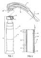
- FIG. 1is a perspective view of a first embodiment of a laryngoscope of present invention, a first embodiment of a laryngoscope handle apparatus of the present invention, a laryngoscope blade and illustrates the mounting of the laryngoscope blade to the laryngoscope handle apparatus;
- FIG. 2is a diagrammatical cross-sectional illustration of the laryngoscope handle of FIG. 1 ;
- FIG. 3is an external vertical view of an LED/battery/lens pack utilized in the first invention embodiments
- FIG. 4is a vertical cross-sectional view taken generally along the line 4 - 4 in FIG. 3 and in the direction of the arrows;
- FIG. 5is an exploded diagrammatical illustration, partially in cross-section, illustrating the mounting of the head and the LED/battery/lens pack to the laryngoscope handle;
- FIG. 6is a vertical external view of the first embodiment of the laryngoscope handle apparatus of the present invention.
- FIG. 7is a vertical cross section of a laryngoscope handle apparatus of FIG. 6 taken generally along the line 7 - 7 and in the direction of the arrows;
- FIG. 8is a diagrammatical illustration, partially in cross section, illustrating the assembly of the module, lens, lens cover, compression spring and DC batteries to the case or casing and showing the casing as initially formed in two halves or sections;
- FIG. 8Ais a top view of the case sections 36 and 37 shown in FIG. 8 ;
- FIG. 8Bis a top view of the case sections 36 and 37 assembled and mounted together;
- FIG. 9is a diagrammatical assembly view illustrating the assembly of the module, compression spring, and negative conductor to the batteries or DC energy source;
- FIG. 10is a perspective view of the negative conductor included in the first laryngoscope handle invention embodiment
- FIG. 11is a diagrammatical vertical cross-sectional view of a first module including an LED and printed circuit board containing an LED drive circuit used in the first laryngoscope and first laryngoscope handle apparatus invention embodiments;
- FIG. 12is a view taken generally along the line 12 - 12 in FIG. 11 and in the direction of the arrows;
- FIG. 12Ais a partial view of a diagrammatical illustration of the mounting of the lens cover to the heat sink of the module shown in FIG. 11 ;
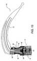
- FIG. 13is a partial cross-sectional view of the upper portion of the first laryngoscope invention embodiment showing the laryngoscope blade pivoted for tracheal intubation and illustrating the manner in which the base of the blade engages the lens cover and forces it downwardly to complete the circuit between the DC energy source and the LED drive circuit for energizing the LED and providing illuminated tracheal intubation;
- FIG. 14is a perspective view of a second embodiment of a laryngoscope of the present invention, a second embodiment of a laryngoscope handle apparatus of the present invention, a laryngoscope blade and illustrates the mounting of the blade to the laryngoscope handle apparatus;
- FIG. 15is a vertical external view of the second embodiment of the laryngoscope handle apparatus of the present invention.
- FIG. 16is a top view of FIG. 15 ;
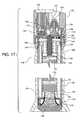
- FIG. 17is a vertical cross-sectional view taken generally along the line 17 - 17 in FIG. 16 and in the direction of the arrows;
- FIG. 18is a vertical cross-sectional view taken generally along the line 18 - 18 in FIG. 16 and in the direction of the arrows;
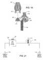
- FIG. 20is an illustration of the mounting of the laryngoscope to the laryngoscope handle apparatus to close the normally open switch to provide illuminated tracheal intubation;
- FIG. 21is a simplified diagrammatical schematic illustrating the normally open positive battery connection to the LED drive circuit
- FIG. 22is a vertical cross-sectional view of a third embodiment of a laryngoscope of the present invention.
- FIG. 23is a vertical cross-sectional view of a fourth embodiment of a laryngoscope of the present invention.
- the laryngoscope 10includes laryngoscope handle apparatus, indicated by general numerical designation 12 , and a laryngoscope blade of a type known to the art indicated by general numerical designation 14 , and in which an optical fiber 15 is mounted in the manner known to the art.
- the laryngoscope handle apparatus 12includes an ergonomic laryngoscope handle, indicated by general designation 16 , and a head, indicated by general numerical designation 18 , mounted to the upper end of the ergonomic handle 16 .
- the laryngoscope blade 14is provided with an inwardly curved surface 20 for engaging the cylindrical rod 21 provided at the top of the head 18 in the manner known to the art and as indicated by the dashed line in FIG. 1 , to mount the laryngoscope blade 14 removably and pivotally to the head 18 and to the laryngoscope handle apparatus 12 .
- the ergonomic laryngoscope handle 16includes a hollow rigid inner cylinder 22 and a generally cylindrical outer soft layer of material 24 molded around the rigid inner cylinder, in a manner known to the art, and having a durometer of about 55 on the Shore A scale.
- the layer of soft material 24includes a generally central portion 25 having a uniform diametrical cross-section, a first outer portion 26 , or upper portion as oriented in FIG. 2 , varying in diametrical cross-section and tapering inwardly at a taper angle A 1 , and a second outer portion 27 , or lower portion as oriented in FIG.
- the rigid inner cylinder 22may be a hollow aluminum cylinder and the layer of soft material 24 may be a thermoplastic vulcanizate, a synthetic thermoplastic rubber such as Santoprene 281-55MED available from the Advanced Elastomer Systems Corporation located in at 388 South Main Street, Akron, Ohio.
- ergonomic handleas used herein and in the appended claims means a handle which provides improved surface area contact between the handle and the hand gripping the handle, which positions the muscles of the hand gripping the handle near the resting position for optimal use of force and control and which minimizes the pressure against the regions of the hand gripping the handle which gripping can cut off circulation to the tissues of the hand.
- Such ergonomic handlereduces hand fatigue resulting from use of the handle.
- the laryngoscope 10includes an LED/battery/lens pack indicated by general designation 30 .
- the pack 30FIG. 4 , includes a casing indicated by general numerical designation 31 , a lens 32 and a module indicated by general numerical designation 34 ; the module 34 includes an LED 35 and is shown in detail in FIG. 11 and described in detailed below.
- the casing 31is generally cylindrical, may be made by injection molding and from a suitable thermoplastic such as Acronitrile Butadiene Styrene (ABS), and is made in two halves or casing sections 36 and 37 as shown in FIG. 8 .
- ABSAcronitrile Butadiene Styrene
- the casing 31provides a lower chamber 38 for receiving a pair of serially connected batteries 39 and 40 which are inserted into the chamber 38 through the opening provided in the lower left portion of the casing 31 shown in FIG. 4 .
- the casing 31further provides a chamber 41 for receiving, generally, the module 34 .
- the pack 30further includes a lens cover 43 in which the lens 32 is mounted and which cover is mounted to the module 34 as described and detailed below.
- the lens cover 43provides an opening 44 at the top through which light from LED 35 is transmitted to and through the lens 32 .
- the upper portion of the lens cover 43is complementary in shape to the upper portion of the lens 32 .
- a generally annular lens spacer 45may be included to locate the lens 32 relative to the LED 35 in an optically correct position in the manner known to the art.
- the lens 32may be a total internal reflection collector made of suitable transparent material and shaped to internally reflect and transmit light emitted by the LED 35 .
- the lens 32is sometimes referred to in the art as a light injector and may be a Fraen Fiber Light Injector (FFLI) available from the Fraen Corporation, 80 New Crossing Road, Reading, Pa.
- the pack 30further includes an electrically conductive compression spring 46 , better seen in FIG. 8 , which, it will be generally understood, biases the module 34 upwardly in the casing chamber 41 .
- the batteries, DC energy source 39 and 40are two M batteries.
- FIG. 5The assembly of the head 18 , ergonomic laryngoscope handle 16 , and LED/battery/lens pack 30 is illustrated in FIG. 5 .
- the lower part of the head 18is provided with internal threads 48 which threadedly engage the external threads 49 provided on the upper portion of the inner rigid cylinder 22 to mount the head to the handle.
- the LED/battery/lens pack 30is inserted upwardly into the handle 16 from the bottom or base as indicated by the dash lines and arrows in FIG.
- FIG. 6An external view, or outline view, of the head 18 mounted to the ergonomic laryngoscope handle 16 , having the LED/battery/lens pack 30 mounted therein is shown in FIG. 6 ; a vertical cross-section view of this assembly is shown in FIG. 7 .
- FIG. 8-12The detailed structure of the LED/battery/lens pack 30 and the electrical connections between the batteries 39 and 40 , and the module 34 are illustrated in FIG. 8-12 .
- the electrically conductive compression spring 46is mounted to the module 34 and these elements, and the lower portion of the lens cover 43 , are inserted into the rightward portion of the chamber 41 provided by the casing section 37 , and the elongated negative conductor 72 , better seen in FIGS. 9 and 10 and described in detail below, is placed in the casing section 37 , after which the casing section 36 is placed in engagement with the casing section 37 and the sections 36 and 37 are suitably mounted together, permanently, such as by a suitable adhesive or by solvent or by ultrasonic welding.
- the module 34includes the LED 35 which is mechanically and electrically mounted to a printed circuit board 54 which contains an LED drive circuit, or LED driving circuit, (not separately shown).
- the LED 35 and LED drive circuit contained in the printed circuit board 54are substantially the same as shown and described in United States Patent Application Publication No. U.S. 2005/0057187 A1, published Mar. 17, 2005, entitled Universal Light Emitting Illumination Device and Method, Anthony Catalano, Inventor.
- This United States Patent Application Publicationis hereby incorporated herein by referenced as fully reproduced herein and is referred to hereinafter as the Catalano reference. More particularly, this Catalano reference note particularly, FIG.
- the module 34includes another printed circuit board indicated by General American Designation 56 made of suitable electrical insulating material and which includes a top surface 57 on which electrical conductors, or electrical traces, 58 and 59 are suitably formed or deposited in the manner known to the art.
- the module 34includes an electrically conductive positive battery contact 60 , suitably mounted mechanically to the printed circuit board 56 , and electrically connected to the electrical trace 58 , such as by soldering as will be understood particularly from FIG. 12 .
- the module 34includes a generally annular heat sink 61 made of suitable heat dissipating and electrically conducted material, such as aluminum, and which heat sink provides an upper inner annular shoulder 62 and a lower inner annular shoulder 63 separated from the first inner annular shoulder by a cylindrical opening 64 .
- the bottom service of the printed circuit board 54includes an outer annular portion residing on the inward annular shoulder 62 and the printed circuit board 56 includes a top surface having an outer annular portion residing on the inward annular shoulder 63 .
- the printed circuit board 54includes a positive lead 66 and a negative lead 67 connected to the LED drive circuit contained in the printed circuit board 54 .
- the positive lead 66extends downwardly through the cylindrical opening 64 and into and through a hole formed in the printed circuit board 56 with the positive lead 66 being mounted mechanically to the printed circuit board 56 and electrically to the electrical trace 58 , note FIG. 12 , such as by soldering; the electrical trace 58 also electrically interconnects the positive lead 66 and the positive battery contact 60 as shown in FIG. 12 .
- the negative lead 67 from the printed circuit board 54FIG.
- FIG. 11extends downwardly through the cylindrical opening 64 and through a hole formed in the printed circuit board 56 with the negative lead 67 being mounted mechanically to the printed circuit board 56 and electrically to the electrical trace 59 as shown in FIG. 12 such as by soldering. It will be understood from FIGS. 11 and 12 that the lower annular portion 61 A of the heat sink 61 is in engagement with the electrical trace 59 , and since as described above the heat sink 61 is electrically conductive, the electrical trace 59 places the heat sink 61 in electrical contact with the negative lead 67 and thereby to the LED drive circuit contained in the printed circuit board 54 .
- the upper portion of the heat sink 61is provided with an inward annular lens cover seating or latching surface 69 which is used to latch the lens cover 43 , FIGS. 4 and 8 , to the heat sink 61 .
- the lens cover 43may be made suitably, such as by injection molding, and of a suitable resilient plastic material, such as ABS and includes an outwardly extending lower annular ring or shoulder 70 , FIG. 12A which, as shown in FIG. 12A , is latched underneath the heat sink seating shoulder 69 to snap-fit the lens cover 43 to the heat sink 61 and thereby mount the lens cover 43 and the lens 32 to the heat sink 61 , this also mounts the lens 32 to the LED 35 as shown FIGS. 4 , 7 and 8 .
- the LED/battery/lens pack 30includes an elongated negative electrical conductor indicated by general numerical designation 72 in FIGS. 9 and 10 .
- the negative conductor 72may be made of suitable electrically conducted material such as brass and may be made suitability, such as by stamping.
- the negative electrical conductor 72particularly FIGS. 9 and 10 , includes an elongated potion 73 and an upper annular portion 74 disposed or bent perpendicularly to the elongated portion 73 .
- the annular portion 74as will be noted particularly from FIG.
- the case or casing section 36is provided with an inward outwardly extending generally C-shaped member 36 A and the case section 37 is provided with two inward outwardly extending members 37 A and 37 B, and upon the case sections being assembled and mounted together, as described above and as shown in FIG. 8B , the members combine to form a generally C-shaped inner seating shoulder 37 C.
- the outer portion of the annular portion 74 of the negative conductor 72resides on, and is supported by, the seating shoulder 37 C in the casing 31 as will be generally understood from FIG. 7 .
- the lower portion 75 of the negative conductor 72is bent or formed inwardly on itself to provide a spring portion which mechanically engages the negative terminal 78 of the battery 39 , note FIG. 9 , and which spring portion 75 biases or forces the batteries 39 and 40 upwardly in the lower case chamber 38 as will be understood from FIG. 8 .
- the heat sink 61is provided with an outer annular compression spring seating shoulder 80 which engages and seats the upper portion of the spring 46 , as shown in FIG. 9 . Accordingly it will be understood from the dashed lines D 1 and D 2 in FIG. 9 , that the upper portion of the electrically conducted compression spring 46 mechanically and electrically engages the lower annular portion 61 A of the heat sink 61 , and that the lower portion of the spring 46 resides on and thereby mechanically and electrically engages the annular portion 74 of the negative conductor 72 . It will be further understood from FIG.
- the negative battery terminal 78is normally connected through the forgoing described negative electrical connection to the LED drive circuit contained in the printed circuit board 54
- the electrically conductive compression spring 46 acting between the annular portion 74 of the negative conductor 72 and heat sink annular shoulder 80 , FIG. 11normally biases the module 34 , the lens 32 and the lens cover 43 , upwardly is viewed in FIG. 7 , and normally maintains the positive battery contact 60 FIG. 11 , out of engagement with the positive terminal 76 , FIG. 9 of the battery 40 .
- FIG. 13it will be understood that upon the Laryngoscope blade 40 being mounted to the head 18 as described above and indicated by the in FIG. 1 , and upon the Laryngoscope blade 14 being pivoted upwardly for tracheal intubation as indicated by the curved arrow 84 in FIG. 1 , the base 86 of the Laryngoscope blade 14 , FIG. 13 is pivoted into engagement with the lens cover 43 and forces the lens cover, lens 42 and module 34 downwardly causing the positive battery contact 60 , to pass through the negative conductor annular portion 74 , FIG. 9 , and engage the positive battery contact 76 , FIG. 9 , thereby completing the positive electrical connection to the LED drive circuit contained in the printed circuit board 54 .
- the DC voltageis applied to the LED drive circuit which produces constant current, as described in the incorporated Catalano reference, and which constant current is applied to the LED 35 causing it to produce and transmit light to the optical fiber 15 mounted in the laryngoscope handle 14 to and through the Lens 42 for illuminated tracheal intubation.
- FIG. 14A second embodiment of a laryngoscope embodying the present invention, and also for providing illuminated tracheal intubation, is shown in FIG. 14 and indicated by general numerical designation 100 .
- the Laryngoscope 100includes Laryngoscope handle apparatus indicated by general numerical designation 102 , and a Laryngoscope blade indicated by general numerical designation 104 , and in which blade an optical fiber 105 is mounted in the manner known to the art.
- the laryngoscope handle apparatus 102includes an ergonomic laryngoscope handle indicated by general numerical designation 106 , and a head indicated by general numerical designation 108 mounted to the upper end of the ergonomic laryngoscope handle 106 .
- the laryngoscope blade 104is provided with an inwardly curved surface 110 for engaging the cylindrical rod 111 provided at the top of the head 108 , in the manner known to the art and as indicated by the dashed line in FIG. 14 , to mount the laryngoscope blade 104 removably and pivotally to the head 108 , and to the laryngoscope handle apparatus 102 .
- the ergonomic laryngoscope handle 106includes the hollow rigid inner aluminum cylinder 22 and the generally cylindrical outer soft layer of material 24 shown in FIG. 2 and described above.
- an LED 112is mounted to a printed circuit board 114 , including an LED drive circuit which is connected to the negative battery terminal 116 through the laryngoscope handle apparatus 106 , as described in detail below, and which is connected to the positive battery terminal 118 through a normally open electrical switch 120 as described in detail below; the switch 120 includes a plunger 121 and a spring 122 .
- a lens, or total internal reflection collector, 124is mounted in the head 108 and to the LED as shown in FIG. 17 .
- a generally annular lens spacer 125may be included to locate the lens 124 relative to the LED 112 in an optically correct position in the manner known to the art.
- the base 128 of the blade 104is pivoted downwardly against the switch plunger 121 , FIG. 17 , to close the normally open electrical switch 120 , and connect the LED drive circuit contained in the printed circuit board 114 to the positive battery terminal 118 , FIG. 17 .
- This connectionsupplies DC voltage from the batteries 131 and 132 , to the LED drive circuit in the printed circuit board 114 which produces and applies constant current, over a broad voltage, to the LED 112 to energize and cause the LED to emit light transmitted through the total internal reflection lens collector 124 to the optical fiber 105 , FIG. 14 for illuminated intubation.
- FIG. 21A diagrammatical schematic of the electrical connection of the LED drive circuit contained in the printed circuit board 114 to the positive and negative battery terminals 116 and 118 , upon the normally open electrical switch 120 being closed, is illustrated in FIG. 21 .
- the batteries 131 and 132are mounted serially in a cylindrical battery casing 134 and are inserted into the bottom of the handle 106 and held in place therein by an electrically conductive spring 138 and an electric conductive end cap 140 .
- the lower portion of the rigid inner cylindrical tube 22is provided with internal threads 142 which threadedly engage the external threads 143 provided on the end cap 140 to mount and seat the batteries in the handle.
- the handle 106is connected mechanically and electrically to the head 108 by an electrically conductive annular adapter 144 .
- the adapter 144is provided with internal threads 145 which threadedly engage the external threads 146 provided on the cylinder 22 to mount the adapter electrically and mechanically to the cylinder 22 .
- the adapter 144is further provided with external threads 147 , which threadedly engage the internal threads 148 formed on the lower portion of the head 108 .
- the head 108is electrically conductive and may be made, for example, of a suitable stainless steel.
- the connection of the LED drive circuit contained in the printed circuit board 114 to the batteries 131 and 132will be understood particularly with reference to FIG. 18 .
- the negative terminal 116 of the battery 132is in mechanical and electrical engagement with the electrically conductive compression spring 138 , which is in electrical and mechanical engagement with the electrically conductive end cap 140 , which in turn is in mechanical electrical engagement with the rigid and electrically conductive inner cylinder 122 , of the handle 106 , which is in mechanical and electrical engagement with the electrically conductive annular adapter 144 , which is in mechanical and electrical engagement with the electrically conductive head 108 .
- the printed circuit board 114is mounted to the head 108 by a pair of electrical conductive screws or bolts 150 and 151 , which extends through holes formed in the printed circuit board 114 and screw into the head 108 .
- the electrically conductive screws 150 , 151mechanically and electrically engage traces, not shown but provided in the printed circuit board 114 in the manner known to the art, to connect the LED drive circuit contained in the printed circuit board 114 to the negative battery terminal 116 through the head, 108 , adapter 144 , cylinder 22 , end cap 140 and the compression spring 138 as described above. Accordingly, it will be understood that the LED drive circuit contained in the printed circuit board 114 is connected to the negative battery terminal 116 through a normally closed negative connection or negative connector circuit.
- FIG. 17The connection of the LED drive circuit contained in the printed circuit board 114 to the positive battery terminal 154 , through a normally open electrical circuit, is illustrated in FIG. 17 .
- a cylindrical, electrically conductive positive battery contact 154is mounted perpendicularly and mechanically at the bottom surface of the printed circuit board 114 and includes an upper, reduced in size, cylindrical portion which extends through a hole formed in the printed circuit board, and the upper portion of the positive battery contact 154 may be mounted mechanically to the circuit board 114 such as by soldering. It will be understood that the positive battery contact 154 does not connect directly to the LED drive circuit contained in the printed circuit board 114 .
- the positive battery contact 154is spaced and maintained centrally of the handle 106 by a battery contact spacer member 156 ; the positive battery spacer 156 may be made of a suitable thermoplastic such as acetal co-polymer.
- the normally open electrical switch 120includes a first switch terminal 158 and a second switch terminal 159 , the switch and switch terminals are also shown in FIG. 19 .
- the switch terminal 158FIG. 17 , is connected to the positive battery contact 154 through a suitable electrical trace provided in the printed circuit board 114 in the manner known to the art.
- the switch terminal 159is connected directly to the LED drive circuit contained in the printed circuit board 114 by a suitable electrical trace provided in the printed circuit board 114 in the manner known to the art.
- the base 128 of laryngoscope blade 104is pivoted downwardly and engages the switch plunger 121 forcing it downwardly against the action of the switch spring 122 , FIG. 19 , interconnecting the switch terminals 158 and 159 , in the manner known to the art, which connects the LED drive circuit contained in the printed circuit board 114 to the positive battery terminal 118 , FIG. 17 through the positive battery contact 154 , the now closed electrical switch 120 .
- the electrical connecting circuit provided by the positive battery contact 154 and the switch 120is a normally open positive battery connection
- a third embodiment of a laryngoscope of the present inventionis shown in vertical cross-section in FIG. 22 and is identified by general numerical designation 200 .
- Laryngoscope 200is the same as the first laryngoscope embodiment 10 shown in FIGS. 1-13 and described above, except that the hollow cylindrical metal handle 202 shown in FIG. 22 replaces the ergonomic handle 16 shown in FIG. 1 .
- the handle 202may be made of a suitable stainless steel and may be knurled to facilitate gripping and handling.
- the lower inner portion of the handle 202is provided with internal threads to threadedly engage the external threads on the end cap 50 and the upper portion of the handle is provided with external threads to threadedly engage the internal threads on the head 18 as shown in FIG. 22 .
- a fourth embodiment of a laryngoscope of the present inventionis shown in vertical cross-section in FIG. 23 and is identified by general designation 300 .
- Laryngoscope 300is the same as the second laryngoscope embodiment 100 shown in FIGS. 14-21 and described above, except that the hollow cylindrical metal handle 302 shown in FIG. 23 replaces the ergonomic handle 106 shown in FIG. 14 .
- the handle 302may be made of a suitable stainless steel and may be knurled to facilitate gripping and handling.
- the lower inner portion of the handle 301is provided with internal threads to threadedly engage the external threads on the end cap 140 and the upper portion of the handle 302 is provided with external threads to threadedly engage the internal threads on the head 108 as shown in FIG. 23 .
- the metal handle 302performs the same function as the aluminum cylinder 22 in FIG. 18 in providing part of the normally closed negative connection between the LED drive circuit and the negative battery terminal as described above in laryngoscope 100 .
Landscapes
- Health & Medical Sciences (AREA)
- Life Sciences & Earth Sciences (AREA)
- Surgery (AREA)
- Physics & Mathematics (AREA)
- Engineering & Computer Science (AREA)
- Optics & Photonics (AREA)
- Biomedical Technology (AREA)
- General Health & Medical Sciences (AREA)
- Pathology (AREA)
- Nuclear Medicine, Radiotherapy & Molecular Imaging (AREA)
- Biophysics (AREA)
- Heart & Thoracic Surgery (AREA)
- Medical Informatics (AREA)
- Molecular Biology (AREA)
- Animal Behavior & Ethology (AREA)
- Radiology & Medical Imaging (AREA)
- Public Health (AREA)
- Veterinary Medicine (AREA)
- Microelectronics & Electronic Packaging (AREA)
- Otolaryngology (AREA)
- Physiology (AREA)
- Pulmonology (AREA)
- Endoscopes (AREA)
Abstract
Description
Claims (28)
Priority Applications (1)
| Application Number | Priority Date | Filing Date | Title |
|---|---|---|---|
| US11/255,323US7771350B2 (en) | 2005-10-21 | 2005-10-21 | Laryngoscope and laryngoscope handle apparatus including an LED and which may include an ergonomic handle |
Applications Claiming Priority (1)
| Application Number | Priority Date | Filing Date | Title |
|---|---|---|---|
| US11/255,323US7771350B2 (en) | 2005-10-21 | 2005-10-21 | Laryngoscope and laryngoscope handle apparatus including an LED and which may include an ergonomic handle |
Publications (2)
| Publication Number | Publication Date |
|---|---|
| US20070093693A1 US20070093693A1 (en) | 2007-04-26 |
| US7771350B2true US7771350B2 (en) | 2010-08-10 |
Family
ID=37986192
Family Applications (1)
| Application Number | Title | Priority Date | Filing Date |
|---|---|---|---|
| US11/255,323Active2029-05-11US7771350B2 (en) | 2005-10-21 | 2005-10-21 | Laryngoscope and laryngoscope handle apparatus including an LED and which may include an ergonomic handle |
Country Status (1)
| Country | Link |
|---|---|
| US (1) | US7771350B2 (en) |
Cited By (15)
| Publication number | Priority date | Publication date | Assignee | Title |
|---|---|---|---|---|
| US20100022843A1 (en)* | 2007-03-11 | 2010-01-28 | Eugeny Pecherer | Laryngoscopes and rechargeable illumination units for use therewith |
| US20110060190A1 (en)* | 2007-08-07 | 2011-03-10 | Truphatek International Ltd. | Laryngoscope apparatus with enhanced viewing capability |
| USD663026S1 (en) | 2010-09-01 | 2012-07-03 | King Systems Corporation | Visualization instrument |
| US8512234B2 (en) | 2011-04-07 | 2013-08-20 | Truphatek International Ltd. | Laryngoscope assembly with enhanced viewing capability |
| USD724208S1 (en) | 2013-06-25 | 2015-03-10 | Intersurgical Ag | Laryngoscope |
| US20150087904A1 (en)* | 2013-02-20 | 2015-03-26 | Olympus Medical Systems Corp. | Endoscope |
| US9179831B2 (en) | 2009-11-30 | 2015-11-10 | King Systems Corporation | Visualization instrument |
| JP2015231551A (en)* | 2010-08-25 | 2015-12-24 | コヴィディエン・アクチェンゲゼルシャフト | Battery driven hand carry ultrasonic surgery cauterizing device |
| US9861382B2 (en) | 2007-12-03 | 2018-01-09 | Covidien Ag | Cordless hand-held ultrasonic cautery cutting device |
| US9872696B2 (en) | 2007-12-03 | 2018-01-23 | Covidien Ag | Battery-powered hand-held ultrasonic surgical cautery cutting device |
| US9924858B2 (en)* | 2011-12-09 | 2018-03-27 | Intersurgical Ag | Laryngoscope |
| US10244922B2 (en) | 2013-09-03 | 2019-04-02 | Truphatek International Ltd. | Single use laryngoscope handle for use in dual component laryngoscope assembly |
| US10426508B2 (en) | 2007-12-03 | 2019-10-01 | Covidien Ag | Cordless hand-held ultrasonic cautery device |
| US11206973B1 (en)* | 2020-09-14 | 2021-12-28 | Kenneth Hiller | Laryngoscope |
| US12185923B2 (en) | 2019-03-14 | 2025-01-07 | Teleflex Medical Incorporated | Universal laryngoscope blade for both conventional handles and fiber-illuminated handles |
Families Citing this family (23)
| Publication number | Priority date | Publication date | Assignee | Title |
|---|---|---|---|---|
| US20010042089A1 (en)* | 1996-01-22 | 2001-11-15 | Tobin William J. | Method and system for customizing marketing services on networks Communicating with hypertext tagging conventions |
| US8142353B2 (en) | 2004-02-29 | 2012-03-27 | Truphatek International Ltd. | Metal laryngoscope blade with illumination assembly |
| USD590501S1 (en)* | 2004-11-30 | 2009-04-14 | Aircraft Medical Limited | Laryngoscope handle |
| JP2009518092A (en) | 2005-12-09 | 2009-05-07 | エアクラフト メディカル リミテッド | Laryngoscope blade |
| US7827985B2 (en)* | 2006-05-01 | 2010-11-09 | Abl Ip Holding Llc | Insertion aid for oral and nasal medical devices |
| US8998806B2 (en)* | 2006-05-01 | 2015-04-07 | Njr Medical, Inc. | Insertion aid for oral and nasal medical devices |
| CA2625548C (en) | 2007-08-04 | 2012-04-10 | John A. Law | An airway intubation device |
| US20090099421A1 (en)* | 2007-10-12 | 2009-04-16 | M.S.Vision Ltd | Intubation laryngoscope with a double holder |
| US8394017B2 (en)* | 2009-01-23 | 2013-03-12 | Lucan Miles Kieffer | Battlefield laryngoscope adaptor cap for flashlight |
| JP5733726B2 (en)* | 2009-11-02 | 2015-06-10 | 公立大学法人名古屋市立大学 | Larynx enlargement tool |
| FR2971692B1 (en)* | 2011-02-21 | 2014-01-03 | Jacques Pierre Christian Vincent | DEVICE FOR FACILITATING THE PLACEMENT AND / OR EXTRACTION OF THE REMOVABLE BLADE ON THE HANDLE OF A LARYNGOSCOPE |
| US8715171B2 (en)* | 2011-06-28 | 2014-05-06 | Njr Medical, Inc. | Insertion aid device |
| RU2705046C2 (en) | 2013-04-01 | 2019-11-01 | Винод В. ПАТХИ | Lighting device |
| USD938095S1 (en) | 2013-04-01 | 2021-12-07 | Pathy Medical, Llc | Lighting device |
| US8974472B2 (en) | 2013-04-16 | 2015-03-10 | Calcula Technologies, Inc. | Method for removing kidney stones |
| US10219864B2 (en) | 2013-04-16 | 2019-03-05 | Calcula Technologies, Inc. | Basket and everting balloon with simplified design and control |
| US10188411B2 (en) | 2013-04-16 | 2019-01-29 | Calcula Technologies, Inc. | Everting balloon for medical devices |
| US20150305603A1 (en)* | 2014-04-23 | 2015-10-29 | Calcula Technologies, Inc. | Integrated medical imaging system |
| EP3490430A4 (en)* | 2016-07-29 | 2020-07-22 | Teleflex Medical Incorporated | Disposable handle assembly and testing device |
| JP6758670B2 (en)* | 2017-01-23 | 2020-09-23 | 学校法人帝京大学 | Tracheal tube insertion aid kit |
| US10334687B2 (en)* | 2017-04-20 | 2019-06-25 | Ngok Wing Jimmy Kwok | Multispectral switch fiber optic lighting laryngoscope |
| US10278572B1 (en) | 2017-10-19 | 2019-05-07 | Obp Medical Corporation | Speculum |
| US10702638B2 (en) | 2018-08-31 | 2020-07-07 | Njr Medical, Inc. | Tracheal and pharyngeal suction device |
Citations (19)
| Publication number | Priority date | Publication date | Assignee | Title |
|---|---|---|---|---|
| US3050049A (en)* | 1958-11-10 | 1962-08-21 | John S Kruglick | Otoscope illumination assembly |
| US4211955A (en) | 1978-03-02 | 1980-07-08 | Ray Stephen W | Solid state lamp |
| US4384570A (en) | 1979-01-02 | 1983-05-24 | Roberts James T | Laryngoscope |
| US4727289A (en) | 1985-07-22 | 1988-02-23 | Stanley Electric Co., Ltd. | LED lamp |
| US4815451A (en)* | 1986-02-18 | 1989-03-28 | Jack Bauman | Submergible larynogoscope with sealed housing for battery |
| US5097180A (en) | 1990-09-14 | 1992-03-17 | Roger Ignon | Flickering candle lamp |
| US5559422A (en) | 1994-07-01 | 1996-09-24 | Welch Allyn, Inc. | Wall transformer |
| US6102851A (en) | 1999-03-25 | 2000-08-15 | Mellin; Carl F. | Laryngoscope with removable light source |
| US6277068B1 (en)* | 1999-09-30 | 2001-08-21 | Welch Allyn, Inc. | Laryngoscope and lamp cartridge assembly |
| US6547394B2 (en) | 1998-10-20 | 2003-04-15 | Victor J. Doherty | Hand-held ophthalmic illuminator |
| WO2003071352A1 (en) | 2002-02-19 | 2003-08-28 | Fraen Corporation S.R.L. | Integrated projection unit in particular for projecting images and/or light beams of predetermined geometry |
| US20030210552A1 (en) | 2002-03-13 | 2003-11-13 | Reinhold Barlian | Indicating light |
| US20040122292A1 (en) | 2001-03-14 | 2004-06-24 | Philip Dey | Laryngoscope |
| EP1433423A1 (en) | 2002-11-15 | 2004-06-30 | Ethicon, Inc. | Tissue biopsy and processing device |
| US20040145891A1 (en) | 2002-12-27 | 2004-07-29 | Heine Optotechnik Gmbh & Co. Kg | Lightning device |
| US20040183482A1 (en) | 2003-03-20 | 2004-09-23 | Welch Allyn, Inc. | Electrical adapter for medical diagnostic instruments using leds as illumination sources |
| JP2005046565A (en) | 2003-07-28 | 2005-02-24 | Daiwa Seisakusho:Kk | Laryngoscope |
| US20050057187A1 (en)* | 2003-09-12 | 2005-03-17 | Technology Assessment Group Inc. | Universal light emitting illumination device and method |
| US6974234B2 (en)* | 2001-12-10 | 2005-12-13 | Galli Robert D | LED lighting assembly |
- 2005
- 2005-10-21USUS11/255,323patent/US7771350B2/enactiveActive
Patent Citations (19)
| Publication number | Priority date | Publication date | Assignee | Title |
|---|---|---|---|---|
| US3050049A (en)* | 1958-11-10 | 1962-08-21 | John S Kruglick | Otoscope illumination assembly |
| US4211955A (en) | 1978-03-02 | 1980-07-08 | Ray Stephen W | Solid state lamp |
| US4384570A (en) | 1979-01-02 | 1983-05-24 | Roberts James T | Laryngoscope |
| US4727289A (en) | 1985-07-22 | 1988-02-23 | Stanley Electric Co., Ltd. | LED lamp |
| US4815451A (en)* | 1986-02-18 | 1989-03-28 | Jack Bauman | Submergible larynogoscope with sealed housing for battery |
| US5097180A (en) | 1990-09-14 | 1992-03-17 | Roger Ignon | Flickering candle lamp |
| US5559422A (en) | 1994-07-01 | 1996-09-24 | Welch Allyn, Inc. | Wall transformer |
| US6547394B2 (en) | 1998-10-20 | 2003-04-15 | Victor J. Doherty | Hand-held ophthalmic illuminator |
| US6102851A (en) | 1999-03-25 | 2000-08-15 | Mellin; Carl F. | Laryngoscope with removable light source |
| US6277068B1 (en)* | 1999-09-30 | 2001-08-21 | Welch Allyn, Inc. | Laryngoscope and lamp cartridge assembly |
| US20040122292A1 (en) | 2001-03-14 | 2004-06-24 | Philip Dey | Laryngoscope |
| US6974234B2 (en)* | 2001-12-10 | 2005-12-13 | Galli Robert D | LED lighting assembly |
| WO2003071352A1 (en) | 2002-02-19 | 2003-08-28 | Fraen Corporation S.R.L. | Integrated projection unit in particular for projecting images and/or light beams of predetermined geometry |
| US20030210552A1 (en) | 2002-03-13 | 2003-11-13 | Reinhold Barlian | Indicating light |
| EP1433423A1 (en) | 2002-11-15 | 2004-06-30 | Ethicon, Inc. | Tissue biopsy and processing device |
| US20040145891A1 (en) | 2002-12-27 | 2004-07-29 | Heine Optotechnik Gmbh & Co. Kg | Lightning device |
| US20040183482A1 (en) | 2003-03-20 | 2004-09-23 | Welch Allyn, Inc. | Electrical adapter for medical diagnostic instruments using leds as illumination sources |
| JP2005046565A (en) | 2003-07-28 | 2005-02-24 | Daiwa Seisakusho:Kk | Laryngoscope |
| US20050057187A1 (en)* | 2003-09-12 | 2005-03-17 | Technology Assessment Group Inc. | Universal light emitting illumination device and method |
Non-Patent Citations (6)
| Title |
|---|
| Beta Fo Laryngoscope Blade Handle System,Heine,1 page,no date. |
| Fiber Optic Laryngoscope Handles,Welsh-Allen, 3 pages,Jul. 1996. |
| Fraen Srl Maximizing Light,6 pages,US,Jul. 22, 2005. |
| Standard Laryngoscope Handles,Heine,no date,1 page. |
| X-Lite Compact,Rusch,1 page,no date. |
| X-Lite Take Apart,Rusch,1 page,no date. |
Cited By (21)
| Publication number | Priority date | Publication date | Assignee | Title |
|---|---|---|---|---|
| US8162826B2 (en)* | 2007-03-11 | 2012-04-24 | Truphatek International Ltd. | Laryngoscopes and rechargeable illumination units for use therewith |
| US20100022843A1 (en)* | 2007-03-11 | 2010-01-28 | Eugeny Pecherer | Laryngoscopes and rechargeable illumination units for use therewith |
| US20110060190A1 (en)* | 2007-08-07 | 2011-03-10 | Truphatek International Ltd. | Laryngoscope apparatus with enhanced viewing capability |
| US8251898B2 (en) | 2007-08-07 | 2012-08-28 | Truphatek International Ltd | Laryngoscope apparatus with enhanced viewing capability |
| US10456158B2 (en) | 2007-12-03 | 2019-10-29 | Covidien Ag | Cordless hand-held ultrasonic surgical device |
| US10426508B2 (en) | 2007-12-03 | 2019-10-01 | Covidien Ag | Cordless hand-held ultrasonic cautery device |
| US9872696B2 (en) | 2007-12-03 | 2018-01-23 | Covidien Ag | Battery-powered hand-held ultrasonic surgical cautery cutting device |
| US9861382B2 (en) | 2007-12-03 | 2018-01-09 | Covidien Ag | Cordless hand-held ultrasonic cautery cutting device |
| US9854962B2 (en) | 2009-11-30 | 2018-01-02 | King Systems Corporation | Visualization instrument |
| US9179831B2 (en) | 2009-11-30 | 2015-11-10 | King Systems Corporation | Visualization instrument |
| JP2015231551A (en)* | 2010-08-25 | 2015-12-24 | コヴィディエン・アクチェンゲゼルシャフト | Battery driven hand carry ultrasonic surgery cauterizing device |
| USD669172S1 (en) | 2010-09-01 | 2012-10-16 | King Systems Corporation | Visualization instrument |
| USD663026S1 (en) | 2010-09-01 | 2012-07-03 | King Systems Corporation | Visualization instrument |
| US8512234B2 (en) | 2011-04-07 | 2013-08-20 | Truphatek International Ltd. | Laryngoscope assembly with enhanced viewing capability |
| US9924858B2 (en)* | 2011-12-09 | 2018-03-27 | Intersurgical Ag | Laryngoscope |
| US20150087904A1 (en)* | 2013-02-20 | 2015-03-26 | Olympus Medical Systems Corp. | Endoscope |
| USD724208S1 (en) | 2013-06-25 | 2015-03-10 | Intersurgical Ag | Laryngoscope |
| US10244922B2 (en) | 2013-09-03 | 2019-04-02 | Truphatek International Ltd. | Single use laryngoscope handle for use in dual component laryngoscope assembly |
| US11219353B2 (en) | 2013-09-03 | 2022-01-11 | Truphatek International Ltd. | Single use laryngoscope handle for use in dual component laryngoscope assembly |
| US12185923B2 (en) | 2019-03-14 | 2025-01-07 | Teleflex Medical Incorporated | Universal laryngoscope blade for both conventional handles and fiber-illuminated handles |
| US11206973B1 (en)* | 2020-09-14 | 2021-12-28 | Kenneth Hiller | Laryngoscope |
Also Published As
| Publication number | Publication date |
|---|---|
| US20070093693A1 (en) | 2007-04-26 |
Similar Documents
| Publication | Publication Date | Title |
|---|---|---|
| US7771350B2 (en) | Laryngoscope and laryngoscope handle apparatus including an LED and which may include an ergonomic handle | |
| US7745957B2 (en) | Combination task lamp and flash light | |
| US7281820B2 (en) | Lighting module assembly and method for a compact lighting device | |
| AU2007246162B2 (en) | A light source apparatus | |
| US7222995B1 (en) | Unitary reflector and lens combination for a light emitting device | |
| US7582838B2 (en) | Flashlight electrical switch and charging indicator | |
| US20070159008A1 (en) | Circuit for illuminating multiple light emitting devices | |
| US7492063B2 (en) | Method of using a single pole single throw switch to provide three operative states | |
| KR20090007769A (en) | Portable lighting unit with waterproof lockout tail cap | |
| US6641279B1 (en) | Dual-beam light assembly with adjustable posterior head | |
| US20020149930A1 (en) | Multi-cell LED flashlight | |
| US5924978A (en) | Portable endoscope system with a bayonet switching mechanism. | |
| MXPA06010407A (en) | Substantial point of light alignment within a reflector. | |
| US20020114154A1 (en) | Reverse operating inline flashlight switch mechanism | |
| US20110261559A1 (en) | Flashlight with Tail Cap and Remote Switch | |
| US6840653B2 (en) | Flashlight head with isolated lighting elements | |
| US20130182424A1 (en) | Handheld lighting device | |
| JP3831014B2 (en) | Endoscope | |
| US330139A (en) | milholland | |
| US20040022061A1 (en) | Warning light device for attaching onto various objects | |
| US20080016709A1 (en) | Illuminated bow sight apparatus | |
| KR200420291Y1 (en) | flashlight | |
| US20030165056A1 (en) | Flashlight | |
| CN211040596U (en) | Little night-light of side direction light-emitting | |
| CN221425202U (en) | Vehicle-mounted refrigerator light structure |
Legal Events
| Date | Code | Title | Description |
|---|---|---|---|
| AS | Assignment | Owner name:VITAL SIGNS, INC., NEW JERSEY Free format text:ASSIGNMENT OF ASSIGNORS INTEREST;ASSIGNORS:GEIST, LEROY D.;JUTTE, LEROY D.;REEL/FRAME:017133/0682 Effective date:20051021 | |
| AS | Assignment | Owner name:GENERAL ELECTRIC COMPANY, NEW YORK Free format text:MERGER;ASSIGNOR:VITAL SIGNS, INC.;REEL/FRAME:022597/0586 Effective date:20080723 | |
| STCF | Information on status: patent grant | Free format text:PATENTED CASE | |
| CC | Certificate of correction | ||
| FPAY | Fee payment | Year of fee payment:4 | |
| AS | Assignment | Owner name:CAREFUSION CORPORATION, CALIFORNIA Free format text:ASSIGNMENT OF ASSIGNORS INTEREST;ASSIGNOR:GENERAL ELECTRIC COMPANY;REEL/FRAME:037482/0120 Effective date:20151117 | |
| AS | Assignment | Owner name:CITIZENS BANK, N.A, AS COLLATERAL AGENT, MASSACHUSETTS Free format text:SECURITY AGREEMENT;ASSIGNORS:VYAIRE MEDICAL CAPITAL LLC;VYAIRE MEDICAL CONSUMABLES LLC;VITAL SIGNS, INC.;AND OTHERS;REEL/FRAME:040357/0952 Effective date:20161013 Owner name:CITIZENS BANK, N.A, AS COLLATERAL AGENT, MASSACHUS Free format text:SECURITY AGREEMENT;ASSIGNORS:VYAIRE MEDICAL CAPITAL LLC;VYAIRE MEDICAL CONSUMABLES LLC;VITAL SIGNS, INC.;AND OTHERS;REEL/FRAME:040357/0952 Effective date:20161013 | |
| AS | Assignment | Owner name:VYAIRE MEDICAL CONSUMABLES LLC, CALIFORNIA Free format text:CHANGE OF NAME;ASSIGNOR:KINGSTON RESPIRATORY CONSUMABLES LLC;REEL/FRAME:040648/0028 Effective date:20161007 Owner name:KINGSTON RESPIRATORY CONSUMABLES LLC, NEW JERSEY Free format text:ASSIGNMENT OF ASSIGNORS INTEREST;ASSIGNOR:KINGSTON RESPIRATORY 102 LLC;REEL/FRAME:040648/0047 Effective date:20160929 Owner name:CAREFUSION 2200, INC., CALIFORNIA Free format text:ASSIGNMENT OF ASSIGNORS INTEREST;ASSIGNOR:CAREFUSION CORPORATION;REEL/FRAME:040372/0822 Effective date:20160928 Owner name:KINGSTON RESPIRATORY 102 LLC, NEW JERSEY Free format text:ASSIGNMENT OF ASSIGNORS INTEREST;ASSIGNOR:CAREFUSION 2200, INC.;REEL/FRAME:040372/0928 Effective date:20160928 | |
| MAFP | Maintenance fee payment | Free format text:PAYMENT OF MAINTENANCE FEE, 8TH YEAR, LARGE ENTITY (ORIGINAL EVENT CODE: M1552) Year of fee payment:8 | |
| AS | Assignment | Owner name:VYAIRE MEDICAL CAPITAL LLC, ILLINOIS Free format text:RELEASE BY SECURED PARTY;ASSIGNOR:CITIZENS BANK, N.A.;REEL/FRAME:045779/0035 Effective date:20180416 Owner name:VYAIRE MEDICAL CONSUMABLES LLC, ILLINOIS Free format text:RELEASE BY SECURED PARTY;ASSIGNOR:CITIZENS BANK, N.A.;REEL/FRAME:045779/0035 Effective date:20180416 Owner name:CAREFUSION 202, INC., ILLINOIS Free format text:RELEASE BY SECURED PARTY;ASSIGNOR:CITIZENS BANK, N.A.;REEL/FRAME:045779/0035 Effective date:20180416 Owner name:VITAL SIGNS, INC., ILLINOIS Free format text:RELEASE BY SECURED PARTY;ASSIGNOR:CITIZENS BANK, N.A.;REEL/FRAME:045779/0035 Effective date:20180416 | |
| AS | Assignment | Owner name:BANK OF AMERICA, N.A., AS COLLATERAL AGENT, NORTH CAROLINA Free format text:FIRST LIEN SECURITY AGREEMENT;ASSIGNOR:VYAIRE MEDICAL CONSUMABLES LLC;REEL/FRAME:045968/0940 Effective date:20180416 Owner name:WILMINGTON TRUST, NATIONAL ASSOCIATION, AS COLLATERAL AGENT, DELAWARE Free format text:SECOND LIEN SECURITY AGREEMENT;ASSIGNOR:VYAIRE MEDICAL CONSUMABLES LLC;REEL/FRAME:045969/0830 Effective date:20180416 Owner name:BANK OF AMERICA, N.A., AS COLLATERAL AGENT, NORTH Free format text:FIRST LIEN SECURITY AGREEMENT;ASSIGNOR:VYAIRE MEDICAL CONSUMABLES LLC;REEL/FRAME:045968/0940 Effective date:20180416 Owner name:WILMINGTON TRUST, NATIONAL ASSOCIATION, AS COLLATE Free format text:SECOND LIEN SECURITY AGREEMENT;ASSIGNOR:VYAIRE MEDICAL CONSUMABLES LLC;REEL/FRAME:045969/0830 Effective date:20180416 | |
| AS | Assignment | Owner name:WILMINGTON TRUST, NATIONAL ASSOCIATION, MINNESOTA Free format text:SECURITY INTEREST;ASSIGNOR:VYAIRE MEDICAL CONSUMABLES LLC;REEL/FRAME:049147/0928 Effective date:20190503 | |
| MAFP | Maintenance fee payment | Free format text:PAYMENT OF MAINTENANCE FEE, 12TH YEAR, LARGE ENTITY (ORIGINAL EVENT CODE: M1553); ENTITY STATUS OF PATENT OWNER: LARGE ENTITY Year of fee payment:12 | |
| AS | Assignment | Owner name:VYAIRE MEDICAL CONSUMABLES LLC, ILLINOIS Free format text:RELEASE OF SECURITY INTEREST IN CERTAIN PATENTS PREVIOUSLY RECORDED AT REEL/FRAME (049147/0928);ASSIGNOR:WILMINGTON TRUST, NATIONAL ASSOCIATION, AS COLLATERAL AGENT;REEL/FRAME:063516/0344 Effective date:20230501 Owner name:VYAIRE MEDICAL CONSUMABLES LLC, ILLINOIS Free format text:RELEASE OF SECURITY INTEREST IN CERTAIN PATENTS PREVIOUSLY RECORDED AT REEL/FRAME (045969/0830);ASSIGNOR:WILMINGTON TRUST, NATIONAL ASSOCIATION, AS COLLATERAL AGENT;REEL/FRAME:063515/0930 Effective date:20230501 | |
| AS | Assignment | Owner name:VYAIRE MEDICAL CONSUMABLES LLC, ILLINOIS Free format text:PARTIAL TERMINATION AND RELEASE OF SECURITY INTEREST RECORDED AT 045968/0940, 4/18/2018;ASSIGNOR:BANK OF AMERICA, N.A.;REEL/FRAME:063528/0916 Effective date:20230501 | |
| AS | Assignment | Owner name:SUNMED GROUP HOLDINGS, LLC, MICHIGAN Free format text:ASSIGNMENT OF ASSIGNORS INTEREST;ASSIGNOR:VYAIRE MEDICAL CONSUMABLES LLC;REEL/FRAME:063822/0286 Effective date:20230501 | |
| AS | Assignment | Owner name:MACQUARIE CAPITAL FUNDING LLC, AS ADMINISTRATIVE AGENT, NEW YORK Free format text:SECURITY INTEREST;ASSIGNOR:SUNMED GROUP HOLDINGS, LLC;REEL/FRAME:064164/0730 Effective date:20230629 | |
| AS | Assignment | Owner name:MACQUARIE PF SERVICES LLC, NEW YORK Free format text:ASSIGNMENT OF SECURITY INTEREST IN PATENTS;ASSIGNOR:MACQUARIE CAPITAL FUNDING LLC;REEL/FRAME:069439/0448 Effective date:20241122 |