US7771290B2 - Golf club head and removable weight - Google Patents
Golf club head and removable weightDownload PDFInfo
- Publication number
- US7771290B2 US7771290B2US12/130,435US13043508AUS7771290B2US 7771290 B2US7771290 B2US 7771290B2US 13043508 AUS13043508 AUS 13043508AUS 7771290 B2US7771290 B2US 7771290B2
- Authority
- US
- United States
- Prior art keywords
- cap
- slug
- receptacle
- weight
- club head
- Prior art date
- Legal status (The legal status is an assumption and is not a legal conclusion. Google has not performed a legal analysis and makes no representation as to the accuracy of the status listed.)
- Expired - Fee Related, expires
Links
Images


Classifications
- A—HUMAN NECESSITIES
- A63—SPORTS; GAMES; AMUSEMENTS
- A63B—APPARATUS FOR PHYSICAL TRAINING, GYMNASTICS, SWIMMING, CLIMBING, OR FENCING; BALL GAMES; TRAINING EQUIPMENT
- A63B53/00—Golf clubs
- A63B53/04—Heads
- A—HUMAN NECESSITIES
- A63—SPORTS; GAMES; AMUSEMENTS
- A63B—APPARATUS FOR PHYSICAL TRAINING, GYMNASTICS, SWIMMING, CLIMBING, OR FENCING; BALL GAMES; TRAINING EQUIPMENT
- A63B53/00—Golf clubs
- A63B53/04—Heads
- A63B53/0466—Heads wood-type
- A—HUMAN NECESSITIES
- A63—SPORTS; GAMES; AMUSEMENTS
- A63B—APPARATUS FOR PHYSICAL TRAINING, GYMNASTICS, SWIMMING, CLIMBING, OR FENCING; BALL GAMES; TRAINING EQUIPMENT
- A63B60/00—Details or accessories of golf clubs, bats, rackets or the like
- A—HUMAN NECESSITIES
- A63—SPORTS; GAMES; AMUSEMENTS
- A63B—APPARATUS FOR PHYSICAL TRAINING, GYMNASTICS, SWIMMING, CLIMBING, OR FENCING; BALL GAMES; TRAINING EQUIPMENT
- A63B60/00—Details or accessories of golf clubs, bats, rackets or the like
- A63B60/02—Ballast means for adjusting the centre of mass
- A—HUMAN NECESSITIES
- A63—SPORTS; GAMES; AMUSEMENTS
- A63B—APPARATUS FOR PHYSICAL TRAINING, GYMNASTICS, SWIMMING, CLIMBING, OR FENCING; BALL GAMES; TRAINING EQUIPMENT
- A63B53/00—Golf clubs
- A63B53/04—Heads
- A63B2053/0491—Heads with added weights, e.g. changeable, replaceable
- A—HUMAN NECESSITIES
- A63—SPORTS; GAMES; AMUSEMENTS
- A63B—APPARATUS FOR PHYSICAL TRAINING, GYMNASTICS, SWIMMING, CLIMBING, OR FENCING; BALL GAMES; TRAINING EQUIPMENT
- A63B2209/00—Characteristics of used materials
- A—HUMAN NECESSITIES
- A63—SPORTS; GAMES; AMUSEMENTS
- A63B—APPARATUS FOR PHYSICAL TRAINING, GYMNASTICS, SWIMMING, CLIMBING, OR FENCING; BALL GAMES; TRAINING EQUIPMENT
- A63B53/00—Golf clubs
- A63B53/04—Heads
- A63B53/0433—Heads with special sole configurations
- A—HUMAN NECESSITIES
- A63—SPORTS; GAMES; AMUSEMENTS
- A63B—APPARATUS FOR PHYSICAL TRAINING, GYMNASTICS, SWIMMING, CLIMBING, OR FENCING; BALL GAMES; TRAINING EQUIPMENT
- A63B53/00—Golf clubs
- A63B53/04—Heads
- A63B53/047—Heads iron-type
- A—HUMAN NECESSITIES
- A63—SPORTS; GAMES; AMUSEMENTS
- A63B—APPARATUS FOR PHYSICAL TRAINING, GYMNASTICS, SWIMMING, CLIMBING, OR FENCING; BALL GAMES; TRAINING EQUIPMENT
- A63B53/00—Golf clubs
- A63B53/04—Heads
- A63B53/0487—Heads for putters
Definitions
- This inventiongenerally relates to golf club heads, and more specifically to golf club heads including a removable weight.
- Removable weightshave been incorporated into golf club heads to distribute discretionary mass in order to alter the performance characteristics of the golf clubs.
- weightsmay be incorporated to provide adjustability in characteristics such as swing weight, location of the center of gravity and manipulation of the moment of inertia of a particular golf club head.
- Various weight designshave been utilized that allow the manufacturer and/or consumer to alter the mass properties of a golf club head.
- Palmerdescribes a golf club that includes a threaded opening that receives threaded weight plugs for varying the weight of a cast metal golf club head.
- the threaded openingextends through a rear wall of the golf club head and receives a threaded plug which may be just long enough to fill the opening or it may extend further into the golf club head to increase the weight.
- the threaded openingis tapered so that the plug may be tightened to a desired depth.
- a disadvantage of the threaded weight plugis that it is constructed as a single piece. As a result, torque applied to the weight plug during use of the golf club is transmitted to the threaded portion and may result in the weight plug becoming disengaged, especially with repeated use.
- the removable weightincludes a mass element and a fastener that extends through an aperture in the mass element.
- a golf club head bodyincludes an interior cavity and a recess on a wall of the body. Inside the recess, a threaded opening is provided so that the fastener may extend through the mass element disposed in the recess and into the threaded opening to fasten the mass element in the recess. Because the fastener extends through the mass element and into a threaded opening in the recess, the size of the mass element and the structure of the recess are limited. Additionally, the mass element is visible to the user when installed so less variation is available for the mass element without detrimentally affecting the aesthetics of the club head.
- the inventionis directed to a golf club head and a removable weight. Several embodiments of the present invention are described below.
- a removable weightfor a golf club head including a receptacle.
- the weightgenerally includes a cap and a slug.
- the capincludes a base, a sidewall and a tool engagement feature.
- the sidewallextends from the base to define a recess.
- the tool engagement featureis included in the base so the weight can be manipulated by a user using a tool.
- the side wall of the capincludes an outer surface that is removably coupled to the receptacle when the weight is installed in the club head.
- the slugincludes a retention portion and an extension portion. At least a portion of the retention portion is slidably disposed in the recess, and the extension portion includes an anti-rotation feature that engages the receptacle to prevent relative rotation between the receptacle and the slug.
- a golf club headin another embodiment, includes a body and a weight.
- the bodyincludes a receptacle that includes a cap portion and a seat portion.
- the cap portionis disposed proximate an outer surface of the body and the seat portion is spaced from the outer surface of the body by the cap portion.
- the weightincludes a cap and a slug.
- the capincludes a base and a sidewall that extends from the base and defines a recess.
- the side wallincludes an outer surface that is removably coupled to the cap portion of the receptacle.
- the slugincludes a retention portion and an extension portion. At least a portion of the retention portion is slidably disposed in the recess and the extension portion includes an anti-rotation feature that engages the seat portion of the receptacle to prevent relative rotation between the receptacle and the slug.
- a golf club headin a further embodiment, includes a body and a weight.
- the bodyincludes a receptacle that includes a threaded cap portion and a seat portion.
- the weightincludes a threaded cap, a slug and a retainer.
- the capincludes a base and a sidewall that extends from the base to define a recess.
- the capis threadably coupled to the cap portion of the receptacle.
- the slugincludes a retention portion and an extension portion. At least a portion of the retention portion is slidably disposed in the recess and the extension portion includes an anti-rotation feature that engages the seat portion of the receptacle to prevent relative rotation between the receptacle and the slug.
- the retainerextends across a sliding interface between the cap and the slug.
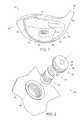
- FIG. 1is a front view of a portion of a golf club head including a weight in accordance with the present invention
- FIG. 2is an exploded view of a portion of the golf club head of FIG. 1 ;
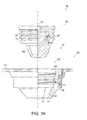
- FIGS. 3A-3Dare partial cross-sectional views of embodiments of a weight and a weight receptacle in a club head in accordance with the present invention.
- FIG. 4is a side view of an embodiment of a cap that is included in the weight of FIGS. 3A-3D ;
- FIG. 5is a cross-sectional view of the cap of FIG. 4 ;
- FIG. 6is a side view of an embodiment weight slug that is included in the weight of FIGS. 3A-3D ;
- FIG. 7is another side view of the weight slug of FIG. 6 ;
- FIG. 8is a cross-sectional view of the weight slug of FIG. 6 ;
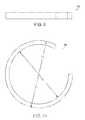
- FIG. 9is a side view of an embodiment of a retainer that is included in the weight of FIG. 3 ;
- FIG. 10is another side view of the retainer of FIG. 9 ;
- FIG. 11is a side view of another embodiment of a weight slug
- FIG. 12is a side view of a further embodiment of a weight slug
- FIG. 13is a side view of a still further embodiment of a weight slug
- FIG. 14is a side view of another embodiment of a weight slug that includes a separate anti-rotation member
- FIG. 15is a side view of another embodiment of a weight slug
- FIG. 16is another side view of the weight slug of FIG. 15 ;
- FIG. 17is a partial cross-sectional view of another embodiment of a weight in accordance with the present invention.
- FIG. 18is a partial cross-sectional view of another embodiment of a weight.
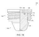
- FIG. 19is a partial cross-sectional view of a further embodiment of a weight.
- the present inventionis directed to a golf club head and a removable weight.
- the removable weightis provided for use with a golf club head to alter the mass properties of the golf club head.
- Golf club head 10generally includes a crown portion 12 , a sole portion 14 , a heel portion 16 , a toe portion 18 , a rear portion 20 , a front portion 22 , a hosel 24 and a weight 26 .
- Front portion 22includes a striking face 23 for impacting a golf ball.
- Crown portion 12extends rearward from front portion 22 and forms a top surface of club head 10 .
- Heel portion 16 , toe portion 18 and rear portion 20combine to form side walls of club head 10 and extend generally downward from the peripheral edge of crown portion 12 to the peripheral edge of sole portion 14 .
- Sole portion 14extends between the lower edges of front portion 22 , heel portion 16 , toe portion 18 and rear portion 20 .
- Hosel 24is a generally tubular member that extends outward from crown portion 12 generally adjacent the intersection of heel portion 16 and front portion 22 .
- a golf club shaftis attached to golf club 10 at hosel 24 .
- an end of the shaftis received in a shaft bore 25 defined by hosel 24 and bonded to hosel 24 .
- hosel 24is one exemplary construction, but any hosel construction may be incorporated into club head 10 .
- Weight receptacle 28is included in one of the components of club head 10 and receives weight 26 .
- club head 10includes a single weight receptacle 28 provided in sole portion 14 .
- any number of weight receptaclesmay be provided in the club head and each weight receptacle 28 may have any location and orientation corresponding to any desired design attribute.
- a plurality of weight receptacles 28may be provided in club head 10 to allow alteration of the location of the center of gravity of club head 10 .
- the center of gravitymay be relocated in a heel to toe direction to impart draw bias or fade bias and/or in a front to rear direction to alter launch angle and spin characteristics.
- the weight receptaclemay be constructed as an integral part of club head 10 or it may be constructed as a separate component and attached to club head 10 . Additionally, in embodiments utilizing a separate receptacle component, the receptacle may be constructed as a full receptacle including both a cap portion and a seat portion, or a partial receptacle including either a cap portion or a seat portion. Furthermore, in a club head constructed from cast components, a full weight receptacle may be cast integral with the corresponding club head component.
- weight receptacle 28is a full receptacle that is a generally tubular or cup-shaped component that is sized and shaped to receive weight 26 .
- weight receptacle 28includes an outer attachment feature 36 that is used to permanently or semi-permanently attach weight receptacle 28 to a portion of club head 10 .
- Outer attachment feature 36may include a threaded surface, a bonding surface and/or a welding surface.
- weight receptacle 28includes outer attachment feature 36 , which is a threaded outer surface that is configured to engage a threaded hole included in club head 10 .
- Receptacle 28includes a bore 38 that extends through a cap portion 40 and a seat portion 42 .
- Cap portion 40is configured to receive and to be removably attached to a cap 30 included in weight 26 .
- An inner attachment feature 46is included in cap portion 40 that allows cap 30 to be removably coupled to receptacle.
- inner attachment feature 46is a threaded surface that engages a threaded outer surface 57 of cap 30 .
- Seat portion 42 of receptacle 28is sized and shaped to receive a portion of a slug 32 that is included in weight 26 .
- Slug portion 42 of receptacleincludes an anti-rotation feature 44 that cooperates with a complementary anti-rotation feature 48 of slug 32 to prevent relative rotation between slug 32 and receptacle 28 when slug 32 is received therein.
- seat portion 42includes a plurality of tapered facets 50 combined so that seat portion 42 is generally tubular and tapered and has a generally polygonal cross-sectional shape.
- the length of seat portion 42may be reduced so that rather than including a plurality of facets seat portion 42 merely includes a polygonal opening sized to abut slug 32 .
- a partial weight receptacle 29includes only a seat portion 35 .
- Seat portion 35includes an outer attachment feature 37 and a plurality of facets 51 .
- outer attachment feature 37is a threaded outer surface that engages a threaded bore in a club head.
- Weight receptacle 29is configured to be threaded into the club head through the outer end of the threaded bore and the threaded bore is preferably threaded only along a portion of its length so that receptacle 29 is prevented from threading past an inner end of the threaded bore and becoming disengaged.
- the threaded bore of the club headis sized to engage the threaded outer surface of cap 30 of weight 26 .
- cap 30is coupled to the threaded bore and slug 32 is coupled to receptacle 29 .
- a toolmay be used to rotate weight receptacle 29 relative to the club head by engaging facets 51 of seat portion 35 or a separate tool engagement feature may be provided.
- Another partial weight receptacle 31includes only a seat portion 39 , as shown in FIG. 3C .
- Seat portion 39includes an outer attachment feature 41 , a plurality of facets 53 and a travel limit flange 43 .
- Outer attachment feature 41is a threaded outer surface that engages a threaded bore in a club head.
- Weight receptacle 31is configured to be threaded into the club head through the inner end of the threaded bore and flange 43 limits the engagement of weight receptacle 31 in the threaded bore. During manufacture, weight receptacle 31 would be installed in the club head prior complete assembly of the club head shell.
- weight receptaclewould be installed in the club head prior to attachment of a separate face insert or a separate crown piece.
- the threaded bore of the club headis sized to engage the threaded outer surface of cap 30 of weight 26 .
- cap 30is coupled to the threaded bore and slug 32 is coupled to receptacle 31 .
- An optional tool engagement feature 45may be included on weight receptacle 31 so that it may be threaded into the threaded bore.
- Tool engagement featuremay be a plurality of facets disposed on flange 43 so that flange 43 is hexagonally shaped and sized to mate with a wrench, such as a socket wrench.
- a partial weight receptacle 33includes only cap portion 47 , as shown in FIG. 3D .
- Cap portion 47includes a generally tubular cylindrical body member 49 and a travel limit flange 55 .
- Receptacle 33is inserted into a bore included in a club head and attached thereto.
- receptacle 33may be bonded, welded and/or staked, such as by dowel pins.
- Receptacle 33includes a threaded inner surface 59 that is sized to engage the threaded outer surface of cap 30 of weight 26 .
- the club headincludes a seat portion including an anti-rotation feature that is preferably integrally cast with the remainder of the club head.
- the receptaclemay be constructed from any metallic or non-metallic material.
- the weight receptaclemay be constructed of titanium, steel, aluminum, tungsten, and/or any alloys of those materials. Including a separate weight receptacle permits the use of materials different than the club head that may be selected to simplify manufacturing of the receptacle.
- Weight 26is assembled from a cap 30 and a weight slug 32 that are movably attached by retainer 34 .
- Cap 30 and slug 32are coupled so that they are able to rotate relative to each other about the longitudinal axis of weight 26 .
- cap 30engages cap portion 40 of receptacle 28 and retains slug 32 within receptacle 28 .
- Cap 30also provides a cover for slug 32 so that when installed in golf club head 10 weight 26 has a desired appearance to a user regardless of the configuration of slug 32 .
- Cap 30is a cup-shaped member formed from a base 54 and side wall 56 that define a recess 52 , as shown in FIGS. 3-5 .
- Recess 52receives at least a portion of slug 32 when weight 26 is installed in club head 10 .
- Side wall 56is a generally annular wall that extends away from base 54 .
- Side wall 56 of cap 30includes threaded outer surface 57 to mate with the threaded inner attachment feature 46 of receptacle 28 . The length and diameter of side wall 56 are selected so that recess 56 may receive a portion of slug 32 .
- retention feature 60may be included in cap 30 so that slug 32 may be movably coupled to cap 30 so that relative rotation between cap 30 and slug 32 is permitted while relative translation is prevented in the assembled weight 26 .
- retention feature 60is a circumferential channel that extends into side wall 56 from the inner surface of side wall 56 and defines a retention flange 61 at an end of side wall 56 opposite base 54 . It should be appreciated that the height of the channel may be as small as approximately equal to the height of retainer 34 , as shown in FIG. 3 , or as large as the distance from retention flange 61 to the surface of base 54 that forms the end of recess 52 .
- a tool engagement feature 58is included in base 54 of cap 30 .
- the tool engagement featureis a feature that mates with a tool manipulated by a user so that weight 26 may be installed or removed from receptacle 28 .
- Tool engagement feature 58is shaped and sized to mate with a complementary tool.
- tool engagement feature 58may be configured to receive a Torx-type wrench (as shown), a screw driver, a spanner wrench or any other standard or custom tool.
- tool engagement feature 58is configured to mate with a tool other than articles that are commonly carried by a golfer during a round of golf (e.g., coins, divot tools and golf tees).
- Slug 32is a mass member that is movably coupled to cap 30 in weight 26 .
- Slug 32is a generally elongate member that includes a retention portion 62 movably coupled to cap 30 and an extension portion 64 that includes anti-rotation feature 48 , as shown in FIGS. 6-8 .
- Retention portion 62is a generally cylindrical portion of slug 32 that has an outer diameter that is less than the inner diameter of side wall 56 so that at least a portion of retention portion 62 is received within recess 56 .
- retention feature 60 of cap 30 , retention portion 62 of slug 32 and retainer 34are dimensioned so that when weight is installed in receptacle 28 retention portion 62 and base 54 of cap 30 are in forced abutment.
- a retention feature 63is included in retention portion 62 of slug 32 that allows slug 32 to be movably coupled to cap 30 .
- retention feature 63is a circumferential channel that extends into slug 32 from an outer surface of retention portion 62 .
- a retainer 34extends from cap 30 and into retention feature 63 and limits relative translation between slug 32 and cap 30 in the direction of the longitudinal axis of weight 26 so that slug 32 is prevented from fully disengaging from cap 30 .
- Extension portion 64 of slug 32engages seat portion 42 of receptacle so that relative rotation between receptacle 28 and slug 32 is prevented when weight 26 is installed.
- extension portion 64 of slug 32includes anti-rotation feature 48 that is generally tapered and has a polygonal cross-sectional shape formed by a plurality of tapered facets 66 that complement facets 50 of seat portion 42 of receptacle 28 .
- portion 64 of slug 32includes a plurality of tapered facets so that the cross-sectional shape of portion 64 is pentagonal and complements the pentagonal cross-sectional shape of seat portion 42 of receptacle 28 .
- seat portion 42 of receptacle 28is tapered, it should be appreciated that seat portion 42 need not be tapered, but instead may have constant cross-sectional shape and size that correspond to the shape and size of an intermediate location along extension 64 .
- slug 32The dimensions and material of slug 32 are selected to provide any desired mass for weight 26 .
- Mass adjustment features 68may be included in slug 32 to fine tune the mass of the member.
- slug 32includes a mass adjustment feature 68 that is a bore extending from an end of portion 64 opposite retention portion 62 . It should be appreciated that the bore may be any depth so that any desired amount of material is removed to reduce the mass of slug 32 .
- the boreis shown extending through slug 32 generally coaxial with the longitudinal axis of slug 32 , it should be appreciated that the bore may have any desired orientation and multiple mass adjustment features may be included.
- Retainer 34is a spring clip in the form of a flexible, semi-circular annular member that is constructed so that it is capable of being elastically deformed between a first configuration and a second configuration.
- retainer 34has a first inner diameter D I that is approximately equal to the minimum diameter of the channel that forms retention feature 63 of slug 32 and a first outer diameter D O that is less than the inner diameter of side wall 56 of cap 30 , and preferably approximately equal to the outer diameter of retention portion 62 of slug 32 .
- retainerhas a second inner diameter D I that is less than the outer diameter of retention portion 62 of slug 32 and a second outer diameter D O that is greater than the inner diameter of wall 56 of cap 30 .
- retainer 34is in the second configuration and is interposed between cap 30 and slug 32 and extends across a sliding interface between cap 30 and slug 32 .
- retainer 34is deformed from the second configuration into the first configuration and is disposed within retention feature 63 so that it and retention portion 62 of slug 32 may be inserted into recess 56 .
- retainer 34is elastically deformed from the second configuration into the first configuration, when slug 32 and cap 30 are positioned so that retention features 60 and 63 align, retainer 34 springs back to the second configuration and extends across the interface between cap 30 and slug 32 to prevent relative translation therebetween.
- Cap 30may also include one or more optional access bores 70 that extend generally radially through side wall 56 and intersect retention feature 60 so that weight 26 may be disassembled. For example, a plurality of rods may be inserted through bores 70 and pressed against the outer wall of retainer 34 so that retainer 34 may be deformed from the second configuration into the first configuration in the assembled weight 26 . Deforming retainer 34 into the first configuration allows slug 32 to be separated from cap 30 .
- Cap 30 , slug 32 and retainer 34may be constructed from any desired materials to provide any desired weights.
- cap 30is constructed of aluminum, slug 32 is constructed of steel and retainer 34 is constructed of stainless steel and weight 26 has a total weight of approximately 8.3 grams.
- cap 30is constructed of aluminum, slug 32 is constructed of a tungsten alloy and retainer 34 is constructed of stainless steel and weight 26 has a total weight of approximately 13.1 grams.
- the density of the material used to construct slug 32is greater than the material used to construct cap 30 , but it should be appreciated that the cap and slug may be constructed from the same material or the slug may be constructed from a material having a density that is less than the density of a material used to construct the cap.
- the weight slugincludes an extension and an anti-rotation feature that is configured to complement a seat portion of the receptacle.
- slug 32includes extension portion 64 that has a generally pentagonal cross-sectional shape. Additional embodiments of an extension portion of the slug are that also provide an anti-rotation feature are illustrated in FIGS. 11-14 .
- slug 72includes an extension 73 that is tapered and has a square cross-sectional shape so that it defines a plurality of tapered facets 74 .
- a slug 76includes an extension 77 that is tapered and has a triangular cross-sectional shape so that it defines three tapered facets 78 .
- slug 80includes an extension 81 that is generally shaped as a truncated cone. Slug 80 further includes a single facet 82 that acts as an anti-rotation feature when mated with the seat portion of a receptacle having a complementary cross-sectional shape. Referring to FIG.
- slug 84includes an extension 85 that is also shaped as a truncated cone, but instead of a facet, extension 85 includes keyway 86 that is sized and shaped to receive a separate anti-rotation member 87 .
- the receptaclealso includes a channel that aligns with keyway 86 to allow insertion of anti-rotation member 87 .
- Slug 90is a mass member that is configured to be movably coupled to a cap of a weight assembly, such as cap 30 of weight 26 .
- Slug 90includes retention portion 92 and extension portion 94 .
- retention portion 92is configured to be removably coupled to a cap, and includes a retention feature 98 that is a channel configured to receive a portion of a retainer.
- Extension portion 94is a generally cylindrical portion that includes an anti-rotation feature 96 .
- anti-rotation feature 96is a tapered rib that extends diametrically across an end of extension portion 94 .
- anti-rotation feature 96is configured to engage a diametric slot included in a corresponding receptacle.
- a slot having a width that is between the maximum and minimum widths of the tapered ribmay be provided or a tapered slot may be provided.
- slug 90includes an optional mass adjustment feature 68 that is a bore extending from an end of extension portion 94 opposite retention portion 92 .
- weight 100includes a cap 102 , a slug 104 and a retainer 106 .
- Retainer 106 of weight 100is a deformable ring that is a complete circular annulus constructed from a deformable material and that extends across a sliding interface between cap 102 and slug 104 .
- Cap 102includes a base 108 and side wall 110 that extends from base 108 to define a recess 112 .
- Base 108includes a tool engagement feature 114 that allows weight 100 to be installed in or removed from a corresponding receptacle.
- Side wall 110includes an attachment feature, such as a threaded outer surface 114 , for coupling cap to a receptacle, and a retention feature 118 for movably coupling cap 102 and slug 104 .
- Retention feature 118is a channel that has a height that is approximately as large as the distance from a retention flange 119 to the surface of base 108 that forms the end of recess 112 .
- a retention portion 120 of slug 104is pressed against base 108 of cap 102 .
- bearing featuresmay be included on the respective components.
- a projection 109extends from base 108 toward retention portion 120 and a complementary projection 121 extends from retention portion toward base 108 .
- Projections 109 and 121are preferably annular and include tapered contact surfaces that abut and slide against each other as weight 100 is installed in a receptacle. Projections may be include on one or both of the cap and slug to provide a reduced contact surface area. Alternatively, a separate bearing feature may be included to reduce the contact surface area, such as a rigid or compressible annular ring interposed between base 108 and retention portion 120 .
- Slug 104includes retention portion 120 and extension portion 122 .
- Retention portion 120extends into recess 112 of cap 102 and is used to retain slug 104 with cap 102 so that the components are free to rotate relative to each other while preventing full disengagement of slug 104 from cap 102 .
- extension portion 122extends from retention portion 120 and engages a seat portion of a corresponding receptacle when weight 100 is installed in a club head.
- the configuration of extension portion 122is substantially identical to those previously described.
- Retention portion 120includes a retention feature 124 that receives a portion of deformable retainer 106 so that retainer 106 is held in place on slug 104 .
- retention feature 124 of the present embodimentis a circumferential channel that extends generally radially into slug 104 from an outer surface of retention portion 120 .
- Weight 100is assembled by installing retainer 106 in retention feature 124 . Then retention portion 120 and retainer 106 are inserted into recess 112 . When retainer 106 is pressed against retention flange 119 , it is forced to deform.
- the inner dimension of retention flange 119is selected so that it is greater than a deformed outer dimension of retainer 106 , but smaller than the free outer dimension of retainer 106 so that as retainer 106 deforms it is able to slide past retention flange 119 and into retention feature 118 . After the deformed retainer 106 passes by retention flange 119 , it is free to deform back to the free outer dimension. Because the inner dimension of retention flange 119 is smaller than the free outer dimension of retainer 106 , retention portion 120 of slug 104 is retained in recess 112 of cap 102 .
- Weight 130includes a cap 132 , a slug 134 and a retainer 136 .
- retainer 136is a member that extends through a side wall 138 of cap 132 , across the interface between cap 132 and slug 134 , and into a retention feature 140 of slug 134 .
- cap 132includes a base 137 and side wall 138 that extends from base 137 to define a recess 142 .
- Base 137includes a tool engagement feature 144 that allows weight 130 to be installed in or removed from a corresponding receptacle.
- Side wall 138includes an attachment feature, such as a threaded outer surface 146 , for coupling cap to a receptacle, and a retention feature 148 for movably coupling cap 132 and slug 134 .
- a single annular projection 151is incorporated that extends from retention portion 150 toward base 137 of cap 132 to reduce contact surface area between retention portion 150 and base 137 .
- Retention feature 148is a bore that extends through side wall 138 .
- Retention feature 148is sized and shaped to receive retainer 136 , which is an elongate member such as a dowel pin or set screw.
- the length of retainer 136is selected so that it extends through side wall 138 and into retention feature 140 of slug.
- the size and shape of retention feature 148is selected according to the configuration of retainer 136 . For example, in embodiments utilizing a dowel pin as retainer 136 , the diameter of retention feature 148 is selected so that the dowel pin is captured in retention feature 148 by a press, or interference fit.
- retention feature 148is a threaded bore sized to threadably engage the set screw. It should be appreciated that any number of retainers 136 may be included that extend through side wall 138 . Additionally, it should be appreciated that retention feature 148 may be configured so that retainer 136 extends through side wall radially or at any angle. For example, retention feature 148 may be configured so retainer 136 extends toward slug 134 approximately normal to retention feature 140 of slug 134 . In another example, retention feature 148 may be configured so retainer 136 extends toward slug 134 so that it is approximately tangent to retention feature 140 of slug 134 .
- Slug 134includes retention portion 150 and extension portion 152 .
- Retention portion 150extends into recess 142 of cap 132 and is used to retain slug 134 with cap 132 so that the components are free to rotate relative to each other while preventing full disengagement of slug 134 from cap 132 .
- extension portion 152extends from retention portion 150 and engages a seat portion of a corresponding receptacle when weight 130 is installed in a club head.
- the configuration of extension portion 152is substantially identical to those previously described.
- Retention portion 150includes a retention feature 140 that receives a portion of retainer 136 in the assembled weight 130 .
- Retention feature 140 of the present embodimentis a circumferential channel that extends generally radially into slug 134 from an outer surface of retention portion 150 .
- Weight 130is assembled by inserting retention portion 150 of slug 134 into recess 142 of cap 132 .
- Retention portion 150is inserted to a position in which retention feature 140 of slug 134 is aligned with retention feature 148 of cap 132 .
- Retainer 136is then inserted through retention feature 148 and into retention feature 140 .
- weight 160includes cap 162 , slug 164 and compression member 166 .
- Cap 162includes a base 168 and side wall 170 that extends from base 168 to define a recess 172 .
- Base 168includes a tool engagement feature 174 that allows weight 160 to be installed in or removed from a corresponding receptacle.
- Slug 164includes retention portion 176 and extension portion 178 .
- Retention portion 176extends into recess 172 of cap 162 and retains slug 164 in coaxial alignment with cap 162 during installation into a corresponding receptacle.
- Retention portion 176is configured so that the components are free to rotate relative to each other during installation.
- extension portion 178extends from retention portion 176 and engages a seat portion of a corresponding receptacle when weight 160 is installed in a club head.
- the configuration of extension portion 178is substantially identical to those previously described.
- Compression member 166is included in weight 160 that is disposed between base 168 of cap 162 and retention portion 176 of slug 164 .
- Compression member 166is an elastic member that is compressed when weight 160 is installed in a receptacle so that extension portion 178 of slug 164 is pressed into a seat portion of the receptacle.
- Compression member 166may have any desired shape, for example, compression member 166 may be disk-shaped or annular, as shown in FIG. 19 .
- Weight 160is assembled by inserting compression member 166 into recess 172 of cap 162 and then inserting retention portion 176 of slug 164 . The weight 160 is then inserted into a receptacle and cap 162 is engaged with a cap portion of the receptacle until compression member 166 is compressed a desired amount to place a selected preload on slug 164 .
- inventive weightis illustrated in a wood-type golf club, it should be appreciated that the weight may be incorporated in any type of golf club.
- inventive weightmay be included in drivers, fairway woods, utility clubs, hybrids, iron-type golf clubs, wedges and putters.
Landscapes
- Health & Medical Sciences (AREA)
- General Health & Medical Sciences (AREA)
- Physical Education & Sports Medicine (AREA)
- Life Sciences & Earth Sciences (AREA)
- Engineering & Computer Science (AREA)
- Wood Science & Technology (AREA)
- Golf Clubs (AREA)
Abstract
Description
Claims (18)
Priority Applications (6)
| Application Number | Priority Date | Filing Date | Title |
|---|---|---|---|
| US12/130,435US7771290B2 (en) | 2008-05-30 | 2008-05-30 | Golf club head and removable weight |
| US12/337,051US8192302B2 (en) | 2008-05-30 | 2008-12-17 | Golf club head and removable weight |
| US12/845,040US8182363B2 (en) | 2008-05-30 | 2010-07-28 | Golf club head and removeable weight |
| US12/852,732US8540589B2 (en) | 2008-05-30 | 2010-08-09 | Golf club head and removable weight |
| US14/033,282US8951145B2 (en) | 2008-05-30 | 2013-09-20 | Golf club head and removable weight |
| US14/616,582US9731173B2 (en) | 2008-05-30 | 2015-02-06 | Golf club head and removable weight |
Applications Claiming Priority (1)
| Application Number | Priority Date | Filing Date | Title |
|---|---|---|---|
| US12/130,435US7771290B2 (en) | 2008-05-30 | 2008-05-30 | Golf club head and removable weight |
Related Child Applications (2)
| Application Number | Title | Priority Date | Filing Date |
|---|---|---|---|
| US12/337,051Continuation-In-PartUS8192302B2 (en) | 2008-05-30 | 2008-12-17 | Golf club head and removable weight |
| US12/845,040ContinuationUS8182363B2 (en) | 2008-05-30 | 2010-07-28 | Golf club head and removeable weight |
Publications (2)
| Publication Number | Publication Date |
|---|---|
| US20090298611A1 US20090298611A1 (en) | 2009-12-03 |
| US7771290B2true US7771290B2 (en) | 2010-08-10 |
Family
ID=41380520
Family Applications (2)
| Application Number | Title | Priority Date | Filing Date |
|---|---|---|---|
| US12/130,435Expired - Fee RelatedUS7771290B2 (en) | 2008-05-30 | 2008-05-30 | Golf club head and removable weight |
| US12/845,040ActiveUS8182363B2 (en) | 2008-05-30 | 2010-07-28 | Golf club head and removeable weight |
Family Applications After (1)
| Application Number | Title | Priority Date | Filing Date |
|---|---|---|---|
| US12/845,040ActiveUS8182363B2 (en) | 2008-05-30 | 2010-07-28 | Golf club head and removeable weight |
Country Status (1)
| Country | Link |
|---|---|
| US (2) | US7771290B2 (en) |
Cited By (59)
| Publication number | Priority date | Publication date | Assignee | Title |
|---|---|---|---|---|
| US20090221380A1 (en)* | 2006-11-27 | 2009-09-03 | Breier Joshua G | Golf club having removable sole weight using custom and interchangeable panels |
| US20100311520A1 (en)* | 2008-05-30 | 2010-12-09 | Stephanie Bezilla | Golf club head and removeable weight |
| US20110143858A1 (en)* | 2009-12-16 | 2011-06-16 | Callaway Golf Company | External weight for golf club head |
| US20120021848A1 (en)* | 2009-12-16 | 2012-01-26 | Callaway Golf Company | Golf club head with composite weight port |
| US20130165251A1 (en)* | 2011-12-27 | 2013-06-27 | Douglas C. Jorgensen | Golf club with reversible sole |
| US20130203518A1 (en)* | 2011-04-28 | 2013-08-08 | Nike, Inc. | Golf clubs and golf club heads |
| US8684863B2 (en) | 2011-12-27 | 2014-04-01 | Acushnet Company | Golf club having removable weight |
| US8696283B1 (en)* | 2012-09-25 | 2014-04-15 | Callaway Golf Company | Weight screw |
| US8753227B1 (en) | 2011-06-14 | 2014-06-17 | Callaway Golf Company | Golf club weight screws |
| US8758165B1 (en)* | 2012-02-28 | 2014-06-24 | Callaway Gold Company | Customizable golf club head |
| US20140187347A1 (en)* | 2012-12-28 | 2014-07-03 | Dunlop Sports Co., Ltd. | Golf club head |
| USD713906S1 (en)* | 2013-08-02 | 2014-09-23 | Callaway Golf Company | Golf club weight port plug |
| USD713905S1 (en)* | 2013-08-02 | 2014-09-23 | Callaway Golf Company | Golf club weight port cap |
| US9095753B2 (en) | 2011-12-27 | 2015-08-04 | Acushnet Company | Golf club having removable weight |
| US9149693B2 (en) | 2009-01-20 | 2015-10-06 | Nike, Inc. | Golf club and golf club head structures |
| US9168435B1 (en) | 2014-06-20 | 2015-10-27 | Nike, Inc. | Golf club head or other ball striking device having impact-influencing body features |
| US9186547B2 (en) | 2011-04-28 | 2015-11-17 | Nike, Inc. | Golf clubs and golf club heads |
| US9192831B2 (en) | 2009-01-20 | 2015-11-24 | Nike, Inc. | Golf club and golf club head structures |
| US9205312B2 (en) | 2011-12-27 | 2015-12-08 | Acushnet Company | Golf club having removable weight |
| US9238162B2 (en) | 2014-04-25 | 2016-01-19 | Cobra Golf Incorporated | Golf club with adjustable weight assembly |
| US9333390B1 (en)* | 2012-06-27 | 2016-05-10 | Callaway Golf Company | Golf club head with adjustable center of gravity and diagnostic features |
| US9375624B2 (en) | 2011-04-28 | 2016-06-28 | Nike, Inc. | Golf clubs and golf club heads |
| US9381410B2 (en) | 2014-05-07 | 2016-07-05 | Acushnet Company | Metal wood club |
| US9393471B2 (en) | 2005-04-21 | 2016-07-19 | Cobra Golf Incorporated | Golf club head with removable component |
| US9409073B2 (en) | 2011-04-28 | 2016-08-09 | Nike, Inc. | Golf clubs and golf club heads |
| US9409076B2 (en) | 2011-04-28 | 2016-08-09 | Nike, Inc. | Golf clubs and golf club heads |
| US9421438B2 (en) | 2005-04-21 | 2016-08-23 | Cobra Golf Incorporated | Golf club head with accessible interior |
| US9433845B2 (en) | 2011-04-28 | 2016-09-06 | Nike, Inc. | Golf clubs and golf club heads |
| US9433834B2 (en) | 2009-01-20 | 2016-09-06 | Nike, Inc. | Golf club and golf club head structures |
| US9433836B2 (en) | 2014-04-25 | 2016-09-06 | Cobra Golf Incorporated | Golf club with adjustable weight assembly |
| US9433844B2 (en) | 2011-04-28 | 2016-09-06 | Nike, Inc. | Golf clubs and golf club heads |
| US9440123B2 (en) | 2005-04-21 | 2016-09-13 | Cobra Golf Incorporated | Golf club head with accessible interior |
| US9504884B2 (en) | 2011-12-27 | 2016-11-29 | Acushnet Company | Golf club having removable weight |
| US9504889B2 (en) | 2005-04-21 | 2016-11-29 | Cobra Golf Incorporated | Golf club with multi-component construction |
| US20160361614A1 (en)* | 2015-06-09 | 2016-12-15 | Dunlop Sports Co. Ltd. | Golf club head |
| US20160375323A1 (en)* | 2012-06-08 | 2016-12-29 | Callaway Golf Company | CG Height Adjustability By Conformal Weighting |
| US9573027B2 (en) | 2011-08-23 | 2017-02-21 | Sri Sports Limited | Weight member for a golf club head |
| US9662551B2 (en) | 2010-11-30 | 2017-05-30 | Nike, Inc. | Golf club head or other ball striking device having impact-influencing body features |
| US9700770B2 (en) | 2011-12-27 | 2017-07-11 | Acushnet Company | Golf club having removeable weight |
| US9731173B2 (en) | 2008-05-30 | 2017-08-15 | Acushnet Company | Golf club head and removable weight |
| US9744415B2 (en) | 2015-12-22 | 2017-08-29 | Acushnet Company | Golf club having removable weight |
| US9764210B2 (en) | 2014-04-25 | 2017-09-19 | Cobra Golf Incorporated | Golf club head with internal cap |
| US9795845B2 (en) | 2009-01-20 | 2017-10-24 | Karsten Manufacturing Corporation | Golf club and golf club head structures |
| US9873029B1 (en) | 2016-08-24 | 2018-01-23 | Wilson Sporting Goods Co. | Golf club head |
| US9908011B2 (en) | 2010-11-30 | 2018-03-06 | Nike, Inc. | Golf club heads or other ball striking devices having distributed impact response |
| US9914028B1 (en) | 2016-09-06 | 2018-03-13 | Acushnet Company | Golf club with movable weight |
| US9975019B2 (en) | 2015-12-22 | 2018-05-22 | Acushnet Company | Golf club with movable weight |
| US10022595B2 (en) | 2016-02-11 | 2018-07-17 | Sumitomo Rubber Industries, Ltd. | Golf club head customization |
| US10035051B2 (en) | 2015-12-22 | 2018-07-31 | Acushnet Company | Golf club with movable weight |
| JP6370462B1 (en)* | 2017-11-27 | 2018-08-08 | 株式会社 ロア・ジャパン | Golf club head, weight set, and method of manufacturing golf club head |
| US20180229091A1 (en)* | 2017-02-13 | 2018-08-16 | Karsten Manufacturing Corporation | Multi-material screw weight |
| US10369437B1 (en) | 2018-08-20 | 2019-08-06 | Acushnet Company | Wood-type golf club including center of gravity adjustment |
| US10780329B2 (en) | 2015-10-06 | 2020-09-22 | Sumitomo Rubber Industries, Ltd. | Multi-component golf club wedge |
| US11497975B2 (en) | 2011-12-27 | 2022-11-15 | Acushnet Company | Golf club having removeable weight |
| US11618213B1 (en) | 2020-04-17 | 2023-04-04 | Cobra Golf Incorporated | Systems and methods for additive manufacturing of a golf club |
| US11618079B1 (en) | 2020-04-17 | 2023-04-04 | Cobra Golf Incorporated | Systems and methods for additive manufacturing of a golf club |
| US11679313B2 (en) | 2021-09-24 | 2023-06-20 | Acushnet Company | Golf club head |
| US12296235B2 (en) | 2023-04-28 | 2025-05-13 | Acushnet Company | Modular golf club including an interchangeable sole |
| US12403362B1 (en) | 2020-04-17 | 2025-09-02 | Cobra Golf Incorporated | Systems and methods for additive manufacturing of a golf club |
Families Citing this family (12)
| Publication number | Priority date | Publication date | Assignee | Title |
|---|---|---|---|---|
| US8197357B1 (en)* | 2009-12-16 | 2012-06-12 | Callaway Golf Company | Golf club head with composite weight port |
| CN102258853B (en)* | 2010-04-15 | 2015-11-25 | 阿库施耐特公司 | There is the golf clubs of dismantled and assembled counterweight |
| JP2013123439A (en)* | 2011-12-13 | 2013-06-24 | Dunlop Sports Co Ltd | Golf club head |
| JP5956861B2 (en)* | 2012-07-17 | 2016-07-27 | ダンロップスポーツ株式会社 | Golf club head |
| JP6257908B2 (en)* | 2013-03-28 | 2018-01-10 | ダンロップスポーツ株式会社 | Golf club head |
| US11951366B2 (en)* | 2014-04-28 | 2024-04-09 | Parsons Xtreme Golf, LLC | Golf club heads and methods to manufacture golf club heads |
| US9814944B1 (en) | 2016-06-30 | 2017-11-14 | Taylor Made Golf Company, Inc. | Golf club head |
| US10543405B2 (en) | 2016-06-30 | 2020-01-28 | Taylor Made Golf Company, Inc. | Golf club head |
| US10786713B2 (en)* | 2016-10-31 | 2020-09-29 | Acushnet Company | Golf club having removable weight |
| JP6420008B1 (en)* | 2018-03-07 | 2018-11-07 | ササキフォージングプレス株式会社 | Golf club head with center of gravity adjustment function |
| US10518143B1 (en) | 2018-06-19 | 2019-12-31 | Taylor Made Golf Company, Inc. | Golf club head |
| US10835791B1 (en)* | 2020-03-02 | 2020-11-17 | Callaway Golf Company | Golf club head with adjustable sole weight |
Citations (28)
| Publication number | Priority date | Publication date | Assignee | Title |
|---|---|---|---|---|
| US1167106A (en) | 1914-06-11 | 1916-01-04 | Oliver M Palmer | Golf-club. |
| US3466047A (en)* | 1966-10-03 | 1969-09-09 | Frank J Rodia | Golf club having adjustable weights |
| US3652094A (en)* | 1969-10-21 | 1972-03-28 | Cecil C Glover | Golf club with adjustable weighting plugs |
| US3692306A (en)* | 1971-02-18 | 1972-09-19 | Cecil C Glover | Golf club having integrally formed face and sole plate with weight means |
| US4026183A (en)* | 1976-05-17 | 1977-05-31 | Illinois Tool Works Inc. | Sealing washer |
| US4043563A (en)* | 1972-08-03 | 1977-08-23 | Roy Alexander Churchward | Golf club |
| US4052075A (en)* | 1976-01-08 | 1977-10-04 | Daly C Robert | Golf club |
| GB2133295A (en)* | 1983-01-12 | 1984-07-25 | Fujiro Kamifuku | A golf club having an adjustably weighted head |
| US5154424A (en)* | 1991-01-07 | 1992-10-13 | Lo Kun Nan | Head of a golf club |
| JPH10137374A (en)* | 1996-11-07 | 1998-05-26 | Injietsukusu:Kk | Golf club head and golf club |
| JPH10234902A (en)* | 1997-02-24 | 1998-09-08 | Daiwa Seiko Inc | Golf club head and mounting of weight member to be mounted at the head |
| JPH10248964A (en)* | 1997-03-13 | 1998-09-22 | Daiwa Seiko Inc | Golf club head, and method for attaching weight to the same |
| JPH11319167A (en)* | 1998-05-01 | 1999-11-24 | Shinsho Son | Golf club |
| US6089994A (en)* | 1998-09-11 | 2000-07-18 | Sun; Donald J. C. | Golf club head with selective weighting device |
| JP2001149514A (en)* | 1999-11-30 | 2001-06-05 | Daiwa Seiko Inc | Golf club head |
| US20040092332A1 (en)* | 2002-11-08 | 2004-05-13 | Willett Kraig A. | Golf club head having a removable weight |
| US20060100029A1 (en)* | 2004-11-09 | 2006-05-11 | Lai-Fa Lo | Golf club head with damping member |
| JP2006122334A (en)* | 2004-10-28 | 2006-05-18 | Fu Sheng Industrial Co Ltd | Vibration absorbing structure of golf club head |
| US20060122004A1 (en)* | 2004-12-06 | 2006-06-08 | Hsin-Hua Chen | Weight adjustable golf club head |
| US7121956B2 (en)* | 2004-10-26 | 2006-10-17 | Fu Sheng Industrial Co., Ltd. | Golf club head with weight member assembly |
| US7186190B1 (en)* | 2002-11-08 | 2007-03-06 | Taylor Made Golf Company, Inc. | Golf club head having movable weights |
| US7294065B2 (en)* | 2005-02-04 | 2007-11-13 | Fu Sheng Industrial Co., Ltd. | Weight assembly for golf club head |
| JP2007313304A (en)* | 2006-04-26 | 2007-12-06 | Yasuyuki Kanamori | Golf putter |
| US20080039229A1 (en)* | 2006-08-09 | 2008-02-14 | Fu Sheng Industrial Co., Ltd. | Golf club head having removable weight |
| US20080132353A1 (en)* | 2006-12-01 | 2008-06-05 | Pen-Long Hsiao | Weight adjustable golf club head |
| US20080146370A1 (en)* | 2006-12-19 | 2008-06-19 | Taylor Made Golf Company, Inc., | Golf club head with repositionable weight |
| US7407447B2 (en)* | 2002-11-08 | 2008-08-05 | Taylor Made Golf Company, Inc. | Movable weights for a golf club head |
| US7419441B2 (en)* | 2002-11-08 | 2008-09-02 | Taylor Made Golf Company, Inc. | Golf club head weight reinforcement |
Family Cites Families (1)
| Publication number | Priority date | Publication date | Assignee | Title |
|---|---|---|---|---|
| US7771290B2 (en)* | 2008-05-30 | 2010-08-10 | Acushnet Company | Golf club head and removable weight |
- 2008
- 2008-05-30USUS12/130,435patent/US7771290B2/ennot_activeExpired - Fee Related
- 2010
- 2010-07-28USUS12/845,040patent/US8182363B2/enactiveActive
Patent Citations (33)
| Publication number | Priority date | Publication date | Assignee | Title |
|---|---|---|---|---|
| US1167106A (en) | 1914-06-11 | 1916-01-04 | Oliver M Palmer | Golf-club. |
| US3466047A (en)* | 1966-10-03 | 1969-09-09 | Frank J Rodia | Golf club having adjustable weights |
| US3652094A (en)* | 1969-10-21 | 1972-03-28 | Cecil C Glover | Golf club with adjustable weighting plugs |
| US3692306A (en)* | 1971-02-18 | 1972-09-19 | Cecil C Glover | Golf club having integrally formed face and sole plate with weight means |
| US4043563A (en)* | 1972-08-03 | 1977-08-23 | Roy Alexander Churchward | Golf club |
| US4052075A (en)* | 1976-01-08 | 1977-10-04 | Daly C Robert | Golf club |
| US4026183A (en)* | 1976-05-17 | 1977-05-31 | Illinois Tool Works Inc. | Sealing washer |
| GB2133295A (en)* | 1983-01-12 | 1984-07-25 | Fujiro Kamifuku | A golf club having an adjustably weighted head |
| US5154424A (en)* | 1991-01-07 | 1992-10-13 | Lo Kun Nan | Head of a golf club |
| JPH10137374A (en)* | 1996-11-07 | 1998-05-26 | Injietsukusu:Kk | Golf club head and golf club |
| JPH10234902A (en)* | 1997-02-24 | 1998-09-08 | Daiwa Seiko Inc | Golf club head and mounting of weight member to be mounted at the head |
| JPH10248964A (en)* | 1997-03-13 | 1998-09-22 | Daiwa Seiko Inc | Golf club head, and method for attaching weight to the same |
| JPH11319167A (en)* | 1998-05-01 | 1999-11-24 | Shinsho Son | Golf club |
| US6089994A (en)* | 1998-09-11 | 2000-07-18 | Sun; Donald J. C. | Golf club head with selective weighting device |
| JP2001149514A (en)* | 1999-11-30 | 2001-06-05 | Daiwa Seiko Inc | Golf club head |
| US6773360B2 (en)* | 2002-11-08 | 2004-08-10 | Taylor Made Golf Company, Inc. | Golf club head having a removable weight |
| US7407447B2 (en)* | 2002-11-08 | 2008-08-05 | Taylor Made Golf Company, Inc. | Movable weights for a golf club head |
| US7452285B2 (en)* | 2002-11-08 | 2008-11-18 | Taylor Made Golf Company, Inc. | Weight kit for golf club head |
| US7419441B2 (en)* | 2002-11-08 | 2008-09-02 | Taylor Made Golf Company, Inc. | Golf club head weight reinforcement |
| US7410426B2 (en)* | 2002-11-08 | 2008-08-12 | Taylor Made Golf Company, Inc. | Golf club head having removable weight |
| US20040092332A1 (en)* | 2002-11-08 | 2004-05-13 | Willett Kraig A. | Golf club head having a removable weight |
| US7186190B1 (en)* | 2002-11-08 | 2007-03-06 | Taylor Made Golf Company, Inc. | Golf club head having movable weights |
| US7223180B2 (en)* | 2002-11-08 | 2007-05-29 | Taylor Made Golf Company, Inc. | Golf club head |
| US7410425B2 (en)* | 2002-11-08 | 2008-08-12 | Taylor Made Golf Company, Inc. | Golf club head having removable weight |
| US7121956B2 (en)* | 2004-10-26 | 2006-10-17 | Fu Sheng Industrial Co., Ltd. | Golf club head with weight member assembly |
| JP2006122334A (en)* | 2004-10-28 | 2006-05-18 | Fu Sheng Industrial Co Ltd | Vibration absorbing structure of golf club head |
| US20060100029A1 (en)* | 2004-11-09 | 2006-05-11 | Lai-Fa Lo | Golf club head with damping member |
| US20060122004A1 (en)* | 2004-12-06 | 2006-06-08 | Hsin-Hua Chen | Weight adjustable golf club head |
| US7294065B2 (en)* | 2005-02-04 | 2007-11-13 | Fu Sheng Industrial Co., Ltd. | Weight assembly for golf club head |
| JP2007313304A (en)* | 2006-04-26 | 2007-12-06 | Yasuyuki Kanamori | Golf putter |
| US20080039229A1 (en)* | 2006-08-09 | 2008-02-14 | Fu Sheng Industrial Co., Ltd. | Golf club head having removable weight |
| US20080132353A1 (en)* | 2006-12-01 | 2008-06-05 | Pen-Long Hsiao | Weight adjustable golf club head |
| US20080146370A1 (en)* | 2006-12-19 | 2008-06-19 | Taylor Made Golf Company, Inc., | Golf club head with repositionable weight |
Cited By (108)
| Publication number | Priority date | Publication date | Assignee | Title |
|---|---|---|---|---|
| US9901794B2 (en) | 2005-04-21 | 2018-02-27 | Cobra Golf Incorporated | Golf club head with removable component |
| US9440123B2 (en) | 2005-04-21 | 2016-09-13 | Cobra Golf Incorporated | Golf club head with accessible interior |
| US9421438B2 (en) | 2005-04-21 | 2016-08-23 | Cobra Golf Incorporated | Golf club head with accessible interior |
| US9393471B2 (en) | 2005-04-21 | 2016-07-19 | Cobra Golf Incorporated | Golf club head with removable component |
| US9504889B2 (en) | 2005-04-21 | 2016-11-29 | Cobra Golf Incorporated | Golf club with multi-component construction |
| US9855474B2 (en) | 2005-04-21 | 2018-01-02 | Cobra Golf Incorporated | Golf club head with accessible interior |
| US8105175B2 (en)* | 2006-11-27 | 2012-01-31 | Acushnet Company | Golf club having removable sole weight using custom and interchangeable panels |
| US20090221380A1 (en)* | 2006-11-27 | 2009-09-03 | Breier Joshua G | Golf club having removable sole weight using custom and interchangeable panels |
| US20100311520A1 (en)* | 2008-05-30 | 2010-12-09 | Stephanie Bezilla | Golf club head and removeable weight |
| US8182363B2 (en)* | 2008-05-30 | 2012-05-22 | Acushnet Company | Golf club head and removeable weight |
| US9731173B2 (en) | 2008-05-30 | 2017-08-15 | Acushnet Company | Golf club head and removable weight |
| US9155944B2 (en) | 2009-01-20 | 2015-10-13 | Nike, Inc. | Golf club and golf club head structures |
| US10130854B2 (en) | 2009-01-20 | 2018-11-20 | Karsten Manufacturing Corporation | Golf club and golf club head structures |
| US9192831B2 (en) | 2009-01-20 | 2015-11-24 | Nike, Inc. | Golf club and golf club head structures |
| US9433834B2 (en) | 2009-01-20 | 2016-09-06 | Nike, Inc. | Golf club and golf club head structures |
| US9446294B2 (en) | 2009-01-20 | 2016-09-20 | Nike, Inc. | Golf club and golf club head structures |
| US9149693B2 (en) | 2009-01-20 | 2015-10-06 | Nike, Inc. | Golf club and golf club head structures |
| US9950219B2 (en) | 2009-01-20 | 2018-04-24 | Karsten Manufacturing Corporation | Golf club and golf club head structures |
| US9795845B2 (en) | 2009-01-20 | 2017-10-24 | Karsten Manufacturing Corporation | Golf club and golf club head structures |
| US20120021848A1 (en)* | 2009-12-16 | 2012-01-26 | Callaway Golf Company | Golf club head with composite weight port |
| US20110143858A1 (en)* | 2009-12-16 | 2011-06-16 | Callaway Golf Company | External weight for golf club head |
| US8414422B2 (en)* | 2009-12-16 | 2013-04-09 | Callaway Golf Company | External weight for golf club head |
| US8444506B2 (en)* | 2009-12-16 | 2013-05-21 | Callaway Golf Company | Golf club head with composite weight port |
| US9914025B2 (en) | 2010-11-30 | 2018-03-13 | Nike, Inc. | Golf club heads or other ball striking devices having distributed impact response |
| US9908011B2 (en) | 2010-11-30 | 2018-03-06 | Nike, Inc. | Golf club heads or other ball striking devices having distributed impact response |
| US9908012B2 (en) | 2010-11-30 | 2018-03-06 | Nike, Inc. | Golf club heads or other ball striking devices having distributed impact response |
| US10610746B2 (en) | 2010-11-30 | 2020-04-07 | Nike, Inc. | Golf club heads or other ball striking devices having distributed impact response |
| US10071290B2 (en) | 2010-11-30 | 2018-09-11 | Nike, Inc. | Golf club heads or other ball striking devices having distributed impact response |
| US9662551B2 (en) | 2010-11-30 | 2017-05-30 | Nike, Inc. | Golf club head or other ball striking device having impact-influencing body features |
| US9409073B2 (en) | 2011-04-28 | 2016-08-09 | Nike, Inc. | Golf clubs and golf club heads |
| US20130203518A1 (en)* | 2011-04-28 | 2013-08-08 | Nike, Inc. | Golf clubs and golf club heads |
| US8986130B2 (en)* | 2011-04-28 | 2015-03-24 | Nike, Inc. | Golf clubs and golf club heads |
| US9375624B2 (en) | 2011-04-28 | 2016-06-28 | Nike, Inc. | Golf clubs and golf club heads |
| US9433844B2 (en) | 2011-04-28 | 2016-09-06 | Nike, Inc. | Golf clubs and golf club heads |
| US9186546B2 (en) | 2011-04-28 | 2015-11-17 | Nike, Inc. | Golf clubs and golf club heads |
| US9403078B2 (en) | 2011-04-28 | 2016-08-02 | Nike, Inc. | Golf clubs and golf club heads |
| US9440127B2 (en) | 2011-04-28 | 2016-09-13 | Nike, Inc. | Golf clubs and golf club heads |
| US9409076B2 (en) | 2011-04-28 | 2016-08-09 | Nike, Inc. | Golf clubs and golf club heads |
| US9186547B2 (en) | 2011-04-28 | 2015-11-17 | Nike, Inc. | Golf clubs and golf club heads |
| US9433845B2 (en) | 2011-04-28 | 2016-09-06 | Nike, Inc. | Golf clubs and golf club heads |
| US8753227B1 (en) | 2011-06-14 | 2014-06-17 | Callaway Golf Company | Golf club weight screws |
| US9573027B2 (en) | 2011-08-23 | 2017-02-21 | Sri Sports Limited | Weight member for a golf club head |
| US10052537B2 (en) | 2011-08-23 | 2018-08-21 | Sri Sports Limited | Weight member for a golf club head |
| US10456641B2 (en) | 2011-08-23 | 2019-10-29 | Sri Sprots Limited | Weight member for a golf club head |
| US9095753B2 (en) | 2011-12-27 | 2015-08-04 | Acushnet Company | Golf club having removable weight |
| US10092803B2 (en) | 2011-12-27 | 2018-10-09 | Acushnet Company | Golf club having removeable weight |
| US20130165251A1 (en)* | 2011-12-27 | 2013-06-27 | Douglas C. Jorgensen | Golf club with reversible sole |
| US9504884B2 (en) | 2011-12-27 | 2016-11-29 | Acushnet Company | Golf club having removable weight |
| US8684863B2 (en) | 2011-12-27 | 2014-04-01 | Acushnet Company | Golf club having removable weight |
| US10092804B2 (en) | 2011-12-27 | 2018-10-09 | Acushnet Company | Golf club having removable weight |
| US11497975B2 (en) | 2011-12-27 | 2022-11-15 | Acushnet Company | Golf club having removeable weight |
| US9700767B2 (en) | 2011-12-27 | 2017-07-11 | Acushnet Company | Golf club having removable weight |
| US9700770B2 (en) | 2011-12-27 | 2017-07-11 | Acushnet Company | Golf club having removeable weight |
| US9216333B2 (en) | 2011-12-27 | 2015-12-22 | Acushnet Company | Golf club having removable weight |
| US10391371B2 (en) | 2011-12-27 | 2019-08-27 | Acushnet Company | Golf club having removeable weight |
| US9205312B2 (en) | 2011-12-27 | 2015-12-08 | Acushnet Company | Golf club having removable weight |
| US8758165B1 (en)* | 2012-02-28 | 2014-06-24 | Callaway Gold Company | Customizable golf club head |
| US20160375323A1 (en)* | 2012-06-08 | 2016-12-29 | Callaway Golf Company | CG Height Adjustability By Conformal Weighting |
| US9981165B2 (en)* | 2012-06-08 | 2018-05-29 | Callaway Golf Company | CG height adjustability by conformal weighting |
| US9333390B1 (en)* | 2012-06-27 | 2016-05-10 | Callaway Golf Company | Golf club head with adjustable center of gravity and diagnostic features |
| US8696283B1 (en)* | 2012-09-25 | 2014-04-15 | Callaway Golf Company | Weight screw |
| US20140186138A1 (en)* | 2012-09-25 | 2014-07-03 | Callaway Golf Company | Weight screw |
| US8915688B2 (en)* | 2012-09-25 | 2014-12-23 | Callaway Golf Company | Weight screw |
| US9358431B2 (en)* | 2012-12-28 | 2016-06-07 | Dunlop Sports Co. Ltd. | Golf club head with removable weight |
| US20140187347A1 (en)* | 2012-12-28 | 2014-07-03 | Dunlop Sports Co., Ltd. | Golf club head |
| USD713905S1 (en)* | 2013-08-02 | 2014-09-23 | Callaway Golf Company | Golf club weight port cap |
| USD713906S1 (en)* | 2013-08-02 | 2014-09-23 | Callaway Golf Company | Golf club weight port plug |
| US9764210B2 (en) | 2014-04-25 | 2017-09-19 | Cobra Golf Incorporated | Golf club head with internal cap |
| US9433836B2 (en) | 2014-04-25 | 2016-09-06 | Cobra Golf Incorporated | Golf club with adjustable weight assembly |
| US9238162B2 (en) | 2014-04-25 | 2016-01-19 | Cobra Golf Incorporated | Golf club with adjustable weight assembly |
| US9968833B2 (en) | 2014-04-25 | 2018-05-15 | Cobra Golf Incorporated | Golf club with adjustable weight assembly |
| US9498686B2 (en) | 2014-04-25 | 2016-11-22 | Cobra Golf Incorporated | Golf club with adjustable weight assembly |
| US10099094B2 (en) | 2014-05-07 | 2018-10-16 | Acushnet Company | Metal wood club |
| US10376757B2 (en) | 2014-05-07 | 2019-08-13 | Acushnet Company | Metal wood club |
| US9700771B2 (en) | 2014-05-07 | 2017-07-11 | Acushnet Company | Metal wood club |
| US9381410B2 (en) | 2014-05-07 | 2016-07-05 | Acushnet Company | Metal wood club |
| US9616299B2 (en) | 2014-06-20 | 2017-04-11 | Nike, Inc. | Golf club head or other ball striking device having impact-influencing body features |
| US9643064B2 (en) | 2014-06-20 | 2017-05-09 | Nike, Inc. | Golf club head or other ball striking device having impact-influencing body features |
| US9168435B1 (en) | 2014-06-20 | 2015-10-27 | Nike, Inc. | Golf club head or other ball striking device having impact-influencing body features |
| US9610480B2 (en) | 2014-06-20 | 2017-04-04 | Nike, Inc. | Golf club head or other ball striking device having impact-influencing body features |
| US9776050B2 (en) | 2014-06-20 | 2017-10-03 | Karsten Manufacturing Corporation | Golf club head or other ball striking device having impact-influencing body features |
| US9789371B2 (en) | 2014-06-20 | 2017-10-17 | Karsten Manufacturing Corporation | Golf club head or other ball striking device having impact-influencing body features |
| US9889346B2 (en) | 2014-06-20 | 2018-02-13 | Karsten Manufacturing Corporation | Golf club head or other ball striking device having impact-influencing body features |
| US9981162B2 (en)* | 2015-06-09 | 2018-05-29 | Dunlop Sports Co. Ltd. | Golf club head |
| US20160361614A1 (en)* | 2015-06-09 | 2016-12-15 | Dunlop Sports Co. Ltd. | Golf club head |
| US10780329B2 (en) | 2015-10-06 | 2020-09-22 | Sumitomo Rubber Industries, Ltd. | Multi-component golf club wedge |
| US10035051B2 (en) | 2015-12-22 | 2018-07-31 | Acushnet Company | Golf club with movable weight |
| US9744415B2 (en) | 2015-12-22 | 2017-08-29 | Acushnet Company | Golf club having removable weight |
| US10391368B2 (en) | 2015-12-22 | 2019-08-27 | Acushnet Company | Golf club with movable weight |
| US9975019B2 (en) | 2015-12-22 | 2018-05-22 | Acushnet Company | Golf club with movable weight |
| US10022595B2 (en) | 2016-02-11 | 2018-07-17 | Sumitomo Rubber Industries, Ltd. | Golf club head customization |
| US11020635B2 (en) | 2016-02-11 | 2021-06-01 | Sumitomo Rubber Industries, Ltd. | Golf club head customization |
| US11524212B2 (en) | 2016-02-11 | 2022-12-13 | Sumitomo Rubber Industries, Ltd. | Golf club head customization |
| US10463924B2 (en) | 2016-02-11 | 2019-11-05 | Sumitomo Rubber Industries, Ltd. | Golf club head customization |
| US12064668B2 (en) | 2016-02-11 | 2024-08-20 | Sumitomo Rubber Industries, Ltd. | Golf club head customization |
| US9873029B1 (en) | 2016-08-24 | 2018-01-23 | Wilson Sporting Goods Co. | Golf club head |
| US9914028B1 (en) | 2016-09-06 | 2018-03-13 | Acushnet Company | Golf club with movable weight |
| US12115422B2 (en)* | 2017-02-13 | 2024-10-15 | Karsten Manufacturing Corporation | Multi-material screw weight |
| US20180229091A1 (en)* | 2017-02-13 | 2018-08-16 | Karsten Manufacturing Corporation | Multi-material screw weight |
| JP6370462B1 (en)* | 2017-11-27 | 2018-08-08 | 株式会社 ロア・ジャパン | Golf club head, weight set, and method of manufacturing golf club head |
| US10646759B2 (en) | 2018-08-20 | 2020-05-12 | Acushnet Company | Wood-type golf club including center of gravity adjustment |
| US10369437B1 (en) | 2018-08-20 | 2019-08-06 | Acushnet Company | Wood-type golf club including center of gravity adjustment |
| US11618079B1 (en) | 2020-04-17 | 2023-04-04 | Cobra Golf Incorporated | Systems and methods for additive manufacturing of a golf club |
| US11618213B1 (en) | 2020-04-17 | 2023-04-04 | Cobra Golf Incorporated | Systems and methods for additive manufacturing of a golf club |
| US12145200B1 (en) | 2020-04-17 | 2024-11-19 | Cobra Golf Incorporated | Systems and methods for additive manufacturing of a golf club |
| US12403362B1 (en) | 2020-04-17 | 2025-09-02 | Cobra Golf Incorporated | Systems and methods for additive manufacturing of a golf club |
| US11679313B2 (en) | 2021-09-24 | 2023-06-20 | Acushnet Company | Golf club head |
| US12296235B2 (en) | 2023-04-28 | 2025-05-13 | Acushnet Company | Modular golf club including an interchangeable sole |
Also Published As
| Publication number | Publication date |
|---|---|
| US8182363B2 (en) | 2012-05-22 |
| US20100311520A1 (en) | 2010-12-09 |
| US20090298611A1 (en) | 2009-12-03 |
Similar Documents
| Publication | Publication Date | Title |
|---|---|---|
| US7771290B2 (en) | Golf club head and removable weight | |
| US9731173B2 (en) | Golf club head and removable weight | |
| US8192302B2 (en) | Golf club head and removable weight | |
| US7744484B1 (en) | Movable weights for a golf club head | |
| US8133131B1 (en) | Interchangeable shaft and club head connection system | |
| US9757628B2 (en) | Interchangeable shaft system | |
| US7294065B2 (en) | Weight assembly for golf club head | |
| US7410425B2 (en) | Golf club head having removable weight | |
| US9364723B2 (en) | Interchangeable shaft system | |
| US9522308B2 (en) | Golf clubs and golf club heads including structure to selectively adjust the face and lie angle of the club head | |
| US20090247316A1 (en) | Interchangeable shaft and club head connection system | |
| US20050096148A1 (en) | Golf club head with shaft locating device | |
| US10188913B2 (en) | Interchangeable shaft system | |
| US9364724B2 (en) | Golf club | |
| JP2024151706A (en) | Club head, golf club, and method for adjusting golf club |
Legal Events
| Date | Code | Title | Description |
|---|---|---|---|
| AS | Assignment | Owner name:ACUSHNET COMPANY, MASSACHUSETTS Free format text:ASSIGNMENT OF ASSIGNORS INTEREST;ASSIGNORS:BEZILLA, STEPHANIE;BENNETT, THOMAS ORRIN;MURPHY, STEPHEN S.;AND OTHERS;SIGNING DATES FROM 20080617 TO 20080618;REEL/FRAME:021374/0135 | |
| STCF | Information on status: patent grant | Free format text:PATENTED CASE | |
| AS | Assignment | Owner name:KOREA DEVELOPMENT BANK, NEW YORK BRANCH, NEW YORK Free format text:SECURITY AGREEMENT;ASSIGNOR:ACUSHNET COMPANY;REEL/FRAME:027332/0829 Effective date:20111031 | |
| FPAY | Fee payment | Year of fee payment:4 | |
| AS | Assignment | Owner name:WELLS FARGO BANK, NATIONAL ASSOCIATION, AS ADMINISTRATIVE AGENT, CALIFORNIA Free format text:SECURITY INTEREST;ASSIGNOR:ACUSHNET COMPANY;REEL/FRAME:039506/0030 Effective date:20160728 Owner name:WELLS FARGO BANK, NATIONAL ASSOCIATION, AS ADMINIS Free format text:SECURITY INTEREST;ASSIGNOR:ACUSHNET COMPANY;REEL/FRAME:039506/0030 Effective date:20160728 | |
| AS | Assignment | Owner name:ACUSHNET COMPANY, MASSACHUSETTS Free format text:RELEASE OF SECURITY INTEREST IN PATENTS PREVIOUSLY RECORDED AT REEL/FRAME (027332/0829);ASSIGNOR:KOREA DEVELOPMENT BANK, NEW YORK BRANCH;REEL/FRAME:039939/0012 Effective date:20160728 | |
| MAFP | Maintenance fee payment | Free format text:PAYMENT OF MAINTENANCE FEE, 8TH YEAR, LARGE ENTITY (ORIGINAL EVENT CODE: M1552) Year of fee payment:8 | |
| FEPP | Fee payment procedure | Free format text:MAINTENANCE FEE REMINDER MAILED (ORIGINAL EVENT CODE: REM.); ENTITY STATUS OF PATENT OWNER: LARGE ENTITY | |
| AS | Assignment | Owner name:JPMORGAN CHASE BANK, N.A., AS SUCCESSOR ADMINISTRATIVE AGENT, ILLINOIS Free format text:ASSIGNMENT OF SECURITY INTEREST IN PATENTS (ASSIGNS 039506-0030);ASSIGNOR:WELLS FARGO BANK, NATIONAL ASSOCIATION, AS RESIGNING ADMINISTRATIVE AGENT;REEL/FRAME:061521/0414 Effective date:20220802 | |
| LAPS | Lapse for failure to pay maintenance fees | Free format text:PATENT EXPIRED FOR FAILURE TO PAY MAINTENANCE FEES (ORIGINAL EVENT CODE: EXP.); ENTITY STATUS OF PATENT OWNER: LARGE ENTITY | |
| STCH | Information on status: patent discontinuation | Free format text:PATENT EXPIRED DUE TO NONPAYMENT OF MAINTENANCE FEES UNDER 37 CFR 1.362 | |
| FP | Lapsed due to failure to pay maintenance fee | Effective date:20220810 |