US7771143B2 - Drill bit assembly with adjustable drill stop sleeve - Google Patents
Drill bit assembly with adjustable drill stop sleeveDownload PDFInfo
- Publication number
- US7771143B2 US7771143B2US11/367,551US36755106AUS7771143B2US 7771143 B2US7771143 B2US 7771143B2US 36755106 AUS36755106 AUS 36755106AUS 7771143 B2US7771143 B2US 7771143B2
- Authority
- US
- United States
- Prior art keywords
- drill
- drill bit
- drill stop
- locking
- stop sleeve
- Prior art date
- Legal status (The legal status is an assumption and is not a legal conclusion. Google has not performed a legal analysis and makes no representation as to the accuracy of the status listed.)
- Active, expires
Links
- 238000005553drillingMethods0.000claimsdescription12
- 238000000034methodMethods0.000claimsdescription11
- 210000000988bone and boneAnatomy0.000description14
- 230000000399orthopedic effectEffects0.000description3
- 238000001356surgical procedureMethods0.000description2
- 230000000712assemblyEffects0.000description1
- 238000000429assemblyMethods0.000description1
- 230000007423decreaseEffects0.000description1
- 238000012986modificationMethods0.000description1
- 230000004048modificationEffects0.000description1
- 230000000149penetrating effectEffects0.000description1
Images


Classifications
- B—PERFORMING OPERATIONS; TRANSPORTING
- B23—MACHINE TOOLS; METAL-WORKING NOT OTHERWISE PROVIDED FOR
- B23B—TURNING; BORING
- B23B49/00—Measuring or gauging equipment on boring machines for positioning or guiding the drill; Devices for indicating failure of drills during boring; Centering devices for holes to be bored
- B23B49/003—Stops attached to drilling tools, tool holders or drilling machines
- A—HUMAN NECESSITIES
- A61—MEDICAL OR VETERINARY SCIENCE; HYGIENE
- A61B—DIAGNOSIS; SURGERY; IDENTIFICATION
- A61B17/00—Surgical instruments, devices or methods
- A61B17/16—Instruments for performing osteoclasis; Drills or chisels for bones; Trepans
- A61B17/1613—Component parts
- A61B17/1633—Sleeves, i.e. non-rotating parts surrounding the bit shaft, e.g. the sleeve forming a single unit with the bit shaft
- A—HUMAN NECESSITIES
- A61—MEDICAL OR VETERINARY SCIENCE; HYGIENE
- A61B—DIAGNOSIS; SURGERY; IDENTIFICATION
- A61B90/00—Instruments, implements or accessories specially adapted for surgery or diagnosis and not covered by any of the groups A61B1/00 - A61B50/00, e.g. for luxation treatment or for protecting wound edges
- A61B90/03—Automatic limiting or abutting means, e.g. for safety
- A61B2090/033—Abutting means, stops, e.g. abutting on tissue or skin
- A61B2090/036—Abutting means, stops, e.g. abutting on tissue or skin abutting on tissue or skin
- B—PERFORMING OPERATIONS; TRANSPORTING
- B23—MACHINE TOOLS; METAL-WORKING NOT OTHERWISE PROVIDED FOR
- B23B—TURNING; BORING
- B23B2260/00—Details of constructional elements
- B23B2260/088—Indication scales
- Y—GENERAL TAGGING OF NEW TECHNOLOGICAL DEVELOPMENTS; GENERAL TAGGING OF CROSS-SECTIONAL TECHNOLOGIES SPANNING OVER SEVERAL SECTIONS OF THE IPC; TECHNICAL SUBJECTS COVERED BY FORMER USPC CROSS-REFERENCE ART COLLECTIONS [XRACs] AND DIGESTS
- Y10—TECHNICAL SUBJECTS COVERED BY FORMER USPC
- Y10T—TECHNICAL SUBJECTS COVERED BY FORMER US CLASSIFICATION
- Y10T408/00—Cutting by use of rotating axially moving tool
- Y10T408/03—Processes
- Y—GENERAL TAGGING OF NEW TECHNOLOGICAL DEVELOPMENTS; GENERAL TAGGING OF CROSS-SECTIONAL TECHNOLOGIES SPANNING OVER SEVERAL SECTIONS OF THE IPC; TECHNICAL SUBJECTS COVERED BY FORMER USPC CROSS-REFERENCE ART COLLECTIONS [XRACs] AND DIGESTS
- Y10—TECHNICAL SUBJECTS COVERED BY FORMER USPC
- Y10T—TECHNICAL SUBJECTS COVERED BY FORMER US CLASSIFICATION
- Y10T408/00—Cutting by use of rotating axially moving tool
- Y10T408/89—Tool or Tool with support
- Y10T408/892—Tool or Tool with support with work-engaging structure detachable from cutting edge
- Y10T408/8925—Depth-limiting member
- Y—GENERAL TAGGING OF NEW TECHNOLOGICAL DEVELOPMENTS; GENERAL TAGGING OF CROSS-SECTIONAL TECHNOLOGIES SPANNING OVER SEVERAL SECTIONS OF THE IPC; TECHNICAL SUBJECTS COVERED BY FORMER USPC CROSS-REFERENCE ART COLLECTIONS [XRACs] AND DIGESTS
- Y10—TECHNICAL SUBJECTS COVERED BY FORMER USPC
- Y10T—TECHNICAL SUBJECTS COVERED BY FORMER US CLASSIFICATION
- Y10T408/00—Cutting by use of rotating axially moving tool
- Y10T408/89—Tool or Tool with support
- Y10T408/907—Tool or Tool with support including detailed shank
Definitions
- the present disclosurerelates generally to orthopedics and orthopedic surgery. More specifically, the present disclosure relates to drill bits used to drill into bone tissue.
- a surgeonmay utilize a surgical drill in order to drill into bone tissue, e.g., in order to establish a hole in which a bone screw, a bone nail, or other device, can be inserted.
- a surgical drillin order to drill into bone tissue, e.g., in order to establish a hole in which a bone screw, a bone nail, or other device, can be inserted.
- the depth of such a holeis critical and the surgeon may not want to drill too deep into the bone tissue. As such, it may be necessary to prevent the drill bit from penetrating too deeply into the bone tissue.
- FIG. 1is a plan view of a drill bit assembly
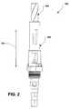
- FIG. 2is another plan view of the drill bit assembly
- FIG. 3is a plan view of a drill bit
- FIG. 4is another plan view of a drill bit
- FIG. 5is a plan view of a drill stop sleeve
- FIG. 6is another plan view of a drill stop sleeve
- FIG. 7is plan view of the locking collar
- FIG. 8is a cross-section view of the drill stop sleeve taken along line 8 - 8 in FIG. 5 with the locking collar rotated into an unlocked position;
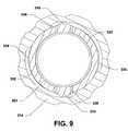
- FIG. 9is another cross-section view of the drill stop sleeve with a locking collar rotated into a locking position
- FIG. 10is a plan view of the drill stop sleeve with the locking collar removed;
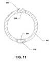
- FIG. 11is a cross-section view of the drill stop sleeve taken along line 11 - 11 in FIG. 10 ;
- FIG. 12is a cross section view of the drill stop sleeve taken along line 12 - 12 in FIG. 10 ;
- FIG. 13is another cross-section view of the drill stop sleeve.
- FIG. 14is a flow chart illustrating a method of using a drill bit assembly.
- a drill bit assemblycan include a drill bit and a drill stop sleeve disposed around the drill bit.
- the drill stop sleevecan include a locking collar that can be movable between an unlocked position and a locked position. In the unlocked position, the drill stop sleeve can be movable along the drill bit to one of a plurality of drill stop depths. In the locked position, the drill stop sleeve can be locked along the drill bit in one of the plurality of drill stop depths.
- a drill bitin another embodiment, can be positioned within a drill stop sleeve.
- the drill bitcan include a plurality of drill stop grooves established therein.
- a drill stop sleevein yet another embodiment, can be positioned around a drill bit.
- the drill stop sleevecan include a locking arm that can be configured to engage one of a plurality of drill stop grooves established within the drill bit.
- a method of drilling a hole in an itemcan include providing a drill bit assembly that includes a drill bit and a drill stop sleeve that can be disposed around the drill bit. Further, the method can include selecting a drill stop depth on a drill bit assembly and locking a drill stop sleeve with respect to a drill bit. The drill stop sleeve can substantially prevent the drill bit from drilling deeper into the item than a selected drill stop depth.
- a kit for field usecan include a drill bit assembly that includes a drill bit and a drill stop sleeve that can be disposed around the drill bit.
- the drill stop sleevecan include a locking collar that can be movable between an unlocked position and a locked position. In the unlocked position, the drill stop sleeve can be moved along the drill bit to one of a plurality of predetermined drill stop depths. Moreover, in the locked position, the drill stop sleeve can be locked along the drill bit in one of the plurality of predetermined drill stop depths.
- the kitcan also include instructions for drilling a hole with the drill bit assembly.
- a drill bit assemblyis shown and is generally designated 100 .
- the drill bit assembly 100includes a drill bit 200 and a drill stop sleeve 300 around the drill bit.
- the drill stop sleeve 300can move back and forth between a plurality of positions relative to the drill bit 200 .
- FIG. 1illustrates the drill bit assembly 100 with the drill stop sleeve 300 in one of the plurality of positions.
- FIG. 2illustrates the drill bit assembly 100 with the drill stop sleeve 300 in another of the plurality of positions.
- the drill bit 200can include a shank 202 and a body 204 extending therefrom.
- the body 204can include a plurality of flutes 206 that can extend helically along the length of the body 204 from the shank 202 to a cutting tip 208 .
- the shank 202can include a first portion 220 , a second portion 222 and a third portion 224 .
- the first portion 220 of the shank 202can include a hexagonal portion 230 that is sized and shaped to be received within a drill chuck, e.g., a keyed drill chuck, a keyless drill chuck, or any other type of drill chuck well known in the art.
- the first portion 220 of the shank 202includes a drill size indicator 232 that is stamped, engraved, or otherwise etched, in the first portion 220 of the shank 202 .
- the drill size indicator 232is a number that indicates the size of the drill bit in standard units or metric units.
- the drill size indicator 232is a number that indicates the size of a screw that is associated with the drill bit, e.g., 5 , 6 , 8 , 10 , 12 , etc.
- FIG. 3 and FIG. 4illustrate that the second portion 222 of the shank 202 can include a plurality of drill stop grooves 240 that are milled or otherwise formed within the second portion 222 of the shank 202 .
- the drill stop grooves 240are equally spaced along the second portion 222 of the shank 202 .
- the drill stop grooves 240are unequally spaced along the second portion 222 of the shank 202 .
- the second portion 222 of the shank 202includes a plurality of depth indicators 242 that can be stamped, engraved, or otherwise etched within the second portion 222 of the shank 202 .
- the depth indicator 242can be a number, e.g., 1, 1.25, 1.5, 1.75, 2, etc., that corresponds to a depth, in metric units or standard units, to which the drill bit assembly 100 can be used to drill into bone tissue.
- the incremental change between the depth indicatorscan correspond to the spacing between adjacent drill stop grooves 240 . For example, if the incremental change between adjacent depth indicators is 0.25 the spacing between adjacent drill stop grooves 240 is 0.25 units, e.g., 0.25 millimeters (0.25 mm).
- the drill stop sleeve 300e.g., an element or elements thereof, can individually engage each of the drill stop grooves 240 . Further, when the drill stop sleeve 300 engages one of the plurality of drill stop grooves 240 , the drill stop sleeve 300 can be locked in place with respect to the drill stop groove 240 . When the drill stop sleeve 300 is locked in place with respect to the drill bit 200 , the depth indicator 242 can be aligned with a depth indicator window established within the drill stop sleeve 300 , and described in detail below, in order to indicate to the user the maximum depth to which the drill bit assembly 100 can drill into bone tissue. For example, if the depth indicator 242 is six (6) and the units associated with the drill bit assembly 100 are millimeters, the user will know that the drill bit assembly cannot drill into bone tissue any deeper than six millimeters (6 mm).
- the drill stop sleeve 300can include a hollow, generally cylindrical first portion 302 and a hollow, generally cylindrical second portion 304 .
- the first portion 302 of the drill stop sleeve 300at least partially surrounds the second portion 222 of the shank 202 of the drill bit 200 .
- the second portion 304 of the drill stop sleeve 300at least partially surrounds the third portion 224 of the shank 202 of the drill bit 200 .
- the first portion 302 of the drill stop sleeve 300can include a first locking arm 310 and a second locking arm 312 . Further, the drill stop sleeve 300 can include a locking collar 314 and a depth indicator window 316 . As described above, each depth indicator 240 of the drill bit 200 can be aligned with the depth indicator window 316 to indicate the maximum depth to which the drill bit assembly 100 can be used to drill into bone tissue.
- the first locking arm 310can include a proximal end 320 and a distal end 322 .
- the proximal end 320 of the first locking arm 310can be attached to, affixed to, or otherwise integrated with, the first portion 302 of the drill stop 300 .
- the distal end 322 of the first locking arm 310can include a locking tooth 324 than can engage the locking grooves 240 established within the second portion 222 of the shank 202 of the drill bit 200 .
- the second locking arm 312is configured substantially identical to the first locking arm 3 - 10 .
- the locking collar 314can include an interior perimeter 330 that can include a first locking surface 330 and a second locking surface 332 established therein.
- Each locking surface 330 , 332can include a leading end 334 and a trailing end 336 .
- a radius of curvature of each locking surface 332 , 334varies along a length of each locking surface 330 , 332 from the leading end 334 of each locking surface 330 , 332 to the trailing end 336 of each locking surface 330 , 332 .
- the radius of curvaturedecreases from the leading end 334 of each locking surface 330 , 332 to the trailing end 336 of each locking surface 330 , 332 .
- the curvature of each locking surface 330 , 332increases from the leading end 334 of each locking surface 330 , 332 to the trailing end 336 of each locking surface 330 , 332 .
- FIG. 8 and FIG. 9illustrate that the locking collar 314 can rotate with respect to the first portion 302 of the drill stop sleeve 300 between an unlocked position, shown in FIG. 8 , and a locked position, shown in FIG. 9 .
- the leading end 334 of the first locking surface 330can be substantially aligned with the first locking arm 310 and the leading end 334 of the second locking surface 332 is substantially aligned with the second locking arm 312 .
- the trailing end 336 of the first locking surface 330can be substantially aligned with the first locking arm 310 and the trailing end 336 of the second locking surface 332 is substantially aligned with the second locking arm 312 .
- each locking surface 330 , 332can engage a respective locking arm 310 , 312 and cause each locking arm 310 , 312 to bend, or deflect, slightly inward with respect to the first portion 302 of the drill stop sleeve 300 .
- each locking arm 310 , 312bends inward, the locking tooth 324 that extends from the distal end 322 of each locking arm 310 , 312 can engage one of the plurality of drill stop grooves 240 established within the second portion 222 of the shank 202 of the drill bit 200 . Further, when each locking tooth 324 is engaged with a drill stop groove 240 , the drill stop sleeve 300 can be locked with respect to the drill bit 200 and the drill stop sleeve 300 can be prevented from moving linearly with respect to the drill bit 200 .
- a usercan slide the drill stop sleeve 300 linearly with respect to the drill bit 200 , or slide the drill bit 200 linearly with respect to the drill stop sleeve 300 , to a selected drill stop depth and rotate the locking collar 314 from the unlocked position to the locked position in order to lock the drill stop sleeve 300 in place with respect to the drill bit 200 .
- the drill stop sleeve 300is locked in place with respect to the drill bit 200 , the drill bit assembly 100 cannot be used to drill any deeper into bone tissue than indicated via the depth indicator 232 on the drill bit 200 that can be seen through the depth indicator window 312 on the drill stop sleeve 300 .
- a drill stop depthcan be determined.
- the drill stop depthcan be determined by a surgeon and correspond to a maximum depth that the surgeon wishes to drill into bone tissue.
- a drill stop sleevecan be slid along a drill bit until a set of locking arms on the drill stop sleeve engage one of the plurality of drill stop grooves on the drill bit.
- the drill stop sleevecan be rotated around the drill bit until a depth indicator on the drill bit can be seen through a depth indicator window on the drill stop sleeve.
- the selected depthcan be determined by viewing the depth indicator through the depth indicator window. If the selected depth is not found, the method returns to block 1402 and continues as described herein.
- the methodproceeds to block 1408 and a locking collar on the drill stop sleeve can be rotated into a locked position.
- the drill bit assemblycan be installed in a drill chuck of a surgical drill.
- one or more holescan be drilled using the drill bit assembly.
- the drill stop sleeve around the drill bitcan substantially prevent the drill bit assembly from drilling deeper into bone tissue than the selected drill stop depth.
- step 1414it can be determined if a new drill stop depth is needed, e.g., to drill one or more holes deeper or shallower than the selected drill stop depth. If a new drill stop depth is necessary, the method proceeds to block 1416 and the drill bit assembly can be removed from the drill chuck of the surgical drill. At block 1418 , the locking collar can be rotated into the unlocked position. Thereafter, the method returns to block 1402 and continues as described herein.
- the methodcan end at state 1420 .
- the drill bit assemblyprovides a device that can be used to select a drill stop depth. Further, when a drill stop depth is selected a drill stop sleeve can prevent a drill bit from drilling into bone tissue deeper than the selected drill stop depth. Accordingly, when a surgeon selects a particular drilling depth, the surgeon can be confident that drilling beyond the selected depth can be substantially prevented.
- a drill bit indexi.e., a kit, can be provided that includes a plurality of drill bit assemblies. Each drill bit assembly can include a drill bit having a particular diameter and each drill bit assembly can be adjusted to prevent the drill bit assembly from drilling beyond a selected depth.
- the locking collarcan be slidably engaged with the drill stop sleeve, e.g., with the first portion of the drill stop sleeve.
- each locking armcan include an outer ramped surface such that the thickness of each locking arm increases from the proximal end of each locking arm to the distal end of each locking arm.
- the locking collarcan be slid along the first portion of the drill stop sleeve from an unlocked position to a locked position. In the unlocked position the locking collar can be substantially aligned with the proximal ends of the locking arms. Further, in the locked position the locking collar can be substantially aligned with the distal ends of the locking arms.
- the locking collarcan engage the outer ramped surfaces of the locking arms and can cause the locking arms to deflect inward in order to cause the locking teeth to engage one of the plurality of drill stop grooves. Moreover, as the locking collar is slid into the unlocked position, the locking collar can disengage the outer ramped surfaces of the locking arms and can cause the locking arms to deflect outward in order to cause the locking teeth to disengage one of the plurality of drill stop grooves.
Landscapes
- Health & Medical Sciences (AREA)
- Engineering & Computer Science (AREA)
- Life Sciences & Earth Sciences (AREA)
- Surgery (AREA)
- Oral & Maxillofacial Surgery (AREA)
- Medical Informatics (AREA)
- Nuclear Medicine, Radiotherapy & Molecular Imaging (AREA)
- Dentistry (AREA)
- Mechanical Engineering (AREA)
- Biomedical Technology (AREA)
- Heart & Thoracic Surgery (AREA)
- Orthopedic Medicine & Surgery (AREA)
- Molecular Biology (AREA)
- Animal Behavior & Ethology (AREA)
- General Health & Medical Sciences (AREA)
- Public Health (AREA)
- Veterinary Medicine (AREA)
- Surgical Instruments (AREA)
Abstract
Description
Claims (13)
Priority Applications (1)
| Application Number | Priority Date | Filing Date | Title |
|---|---|---|---|
| US11/367,551US7771143B2 (en) | 2006-03-03 | 2006-03-03 | Drill bit assembly with adjustable drill stop sleeve |
Applications Claiming Priority (1)
| Application Number | Priority Date | Filing Date | Title |
|---|---|---|---|
| US11/367,551US7771143B2 (en) | 2006-03-03 | 2006-03-03 | Drill bit assembly with adjustable drill stop sleeve |
Publications (2)
| Publication Number | Publication Date |
|---|---|
| US20070206996A1 US20070206996A1 (en) | 2007-09-06 |
| US7771143B2true US7771143B2 (en) | 2010-08-10 |
Family
ID=38471629
Family Applications (1)
| Application Number | Title | Priority Date | Filing Date |
|---|---|---|---|
| US11/367,551Active2028-07-01US7771143B2 (en) | 2006-03-03 | 2006-03-03 | Drill bit assembly with adjustable drill stop sleeve |
Country Status (1)
| Country | Link |
|---|---|
| US (1) | US7771143B2 (en) |
Cited By (41)
| Publication number | Priority date | Publication date | Assignee | Title |
|---|---|---|---|---|
| US20080167653A1 (en)* | 2007-01-05 | 2008-07-10 | Watlington Michael B | Drill bit assembly for bone tissue including depth limiting feature |
| US20100215450A1 (en)* | 2009-02-24 | 2010-08-26 | Black & Decker Inc. | Depth Gauge For Drill Bit |
| US20110110740A1 (en)* | 2009-11-12 | 2011-05-12 | Tsai Fa Liu | Drilling bit with the depth-limiting and angle-leading function for the carpenter's work |
| US20110177469A1 (en)* | 2009-12-17 | 2011-07-21 | Straumann Holding Ag | Dental tools for guided surgery |
| US8088163B1 (en) | 2008-02-06 | 2012-01-03 | Kleiner Jeffrey B | Tools and methods for spinal fusion |
| US20120042764A1 (en)* | 2009-03-25 | 2012-02-23 | Trumpf Werkzeugmaschinen Gmbh + Co. Kg | Punching Tools and Related Machines and Methods |
| USD656610S1 (en) | 2009-02-06 | 2012-03-27 | Kleiner Jeffrey B | Spinal distraction instrument |
| US8366748B2 (en) | 2008-12-05 | 2013-02-05 | Kleiner Jeffrey | Apparatus and method of spinal implant and fusion |
| US20140046383A1 (en)* | 2012-08-09 | 2014-02-13 | Wilson Theophilo Asfora | System for joint fusion |
| US8685031B2 (en) | 2009-09-18 | 2014-04-01 | Spinal Surgical Strategies, Llc | Bone graft delivery system |
| US8864654B2 (en) | 2010-04-20 | 2014-10-21 | Jeffrey B. Kleiner | Method and apparatus for performing retro peritoneal dissection |
| US8906028B2 (en) | 2009-09-18 | 2014-12-09 | Spinal Surgical Strategies, Llc | Bone graft delivery device and method of using the same |
| USD719594S1 (en)* | 2013-11-15 | 2014-12-16 | Mcginley Engineered Solutions, Llc | Drill bit assembly |
| USD723682S1 (en) | 2013-05-03 | 2015-03-03 | Spinal Surgical Strategies, Llc | Bone graft delivery tool |
| USD726792S1 (en)* | 2013-11-27 | 2015-04-14 | Nir Velozny | Drill bit |
| US20150101177A1 (en)* | 2013-10-11 | 2015-04-16 | Irwin Industrial Tool Company | Drilling apparatus and method |
| US9060877B2 (en) | 2009-09-18 | 2015-06-23 | Spinal Surgical Strategies, Llc | Fusion cage with combined biological delivery system |
| US9155545B2 (en) | 2013-10-31 | 2015-10-13 | Enteroptyx, Inc. | Surgical drill handpiece with adjustable cutting tool guard |
| US9173694B2 (en) | 2009-09-18 | 2015-11-03 | Spinal Surgical Strategies, Llc | Fusion cage with combined biological delivery system |
| US9186193B2 (en) | 2009-09-18 | 2015-11-17 | Spinal Surgical Strategies, Llc | Fusion cage with combined biological delivery system |
| US9216048B2 (en) | 2009-03-18 | 2015-12-22 | Integrated Spinal Concepts, Inc. | Image-guided minimal-step placement of screw into bone |
| US9247943B1 (en) | 2009-02-06 | 2016-02-02 | Kleiner Intellectual Property, Llc | Devices and methods for preparing an intervertebral workspace |
| USD750249S1 (en) | 2014-10-20 | 2016-02-23 | Spinal Surgical Strategies, Llc | Expandable fusion cage |
| US9629729B2 (en) | 2009-09-18 | 2017-04-25 | Spinal Surgical Strategies, Llc | Biological delivery system with adaptable fusion cage interface |
| US9717403B2 (en) | 2008-12-05 | 2017-08-01 | Jeffrey B. Kleiner | Method and apparatus for performing retro peritoneal dissection |
| USD797290S1 (en) | 2015-10-19 | 2017-09-12 | Spinal Surgical Strategies, Llc | Bone graft delivery tool |
| US9855060B2 (en) | 2015-06-10 | 2018-01-02 | OrthoDrill Medical Ltd. | Device for modifying the operation of surgical bone tools and/or methods thereof |
| US10245159B1 (en) | 2009-09-18 | 2019-04-02 | Spinal Surgical Strategies, Llc | Bone graft delivery system and method for using same |
| USD853560S1 (en) | 2008-10-09 | 2019-07-09 | Nuvasive, Inc. | Spinal implant insertion device |
| US10433856B2 (en)* | 2016-07-11 | 2019-10-08 | Grace Medical, Inc. | Surgical drill handpiece with adjustable cutting tool guard |
| US10973656B2 (en) | 2009-09-18 | 2021-04-13 | Spinal Surgical Strategies, Inc. | Bone graft delivery system and method for using same |
| US10987116B2 (en) | 2017-12-15 | 2021-04-27 | Medos International Sarl | Adjustable drill guides and related methods |
| US11317927B2 (en) | 2017-08-17 | 2022-05-03 | Stryker Corporation | Measurement module for measuring depth of bore holes and related accessories |
| USD954950S1 (en) | 2020-11-18 | 2022-06-14 | Stryker Corporation | Measurement head for a surgical tool |
| US11504778B2 (en)* | 2018-04-30 | 2022-11-22 | Kreg Enterprises, Inc. | Mini pocket hole jig system |
| US11666455B2 (en) | 2009-09-18 | 2023-06-06 | Spinal Surgical Strategies, Inc., A Nevada Corporation | Bone graft delivery devices, systems and kits |
| US11793558B2 (en) | 2019-08-30 | 2023-10-24 | K2M, Inc. | All in one plate holder and spring loaded awl |
| US11896239B2 (en) | 2017-08-17 | 2024-02-13 | Stryker Corporation | Surgical handpiece system for depth measurement and related accessories |
| US12133654B2 (en) | 2019-05-15 | 2024-11-05 | Stryker Corporation | Powered surgical drill having rotating field bit identification |
| US12279972B2 (en) | 2008-05-22 | 2025-04-22 | Spinal Surgical Strategies, Inc. | Spinal fusion cage system with inserter |
| US12402894B2 (en) | 2019-08-14 | 2025-09-02 | Versah, LLC | Universal keyless guided surgery system |
Families Citing this family (16)
| Publication number | Priority date | Publication date | Assignee | Title |
|---|---|---|---|---|
| US9089901B2 (en)* | 2006-05-10 | 2015-07-28 | Christopher L. White | Flexible and extendible drill bit assembly |
| US8496665B2 (en)* | 2008-02-13 | 2013-07-30 | Biomet C.V. | Drill sleeve |
| US8740513B2 (en)* | 2009-02-24 | 2014-06-03 | Black & Decker Inc. | Dust collector for use with drill bit or drill bit depth stop |
| US8662801B2 (en)* | 2009-02-24 | 2014-03-04 | Black & Decker Inc. | Depth gauge for drill bit |
| US8091866B2 (en)* | 2009-04-09 | 2012-01-10 | Christopher L White | Wire pull assembly |
| USD678369S1 (en) | 2010-02-18 | 2013-03-19 | Black & Decker Inc. | Drill bit |
| US8770898B2 (en) | 2010-05-13 | 2014-07-08 | Greenlee Textron Inc. | Tail piece for an extendable drill bit assembly having a reduced head |
| US9572589B2 (en)* | 2012-07-10 | 2017-02-21 | Stryker European Holdings I, Llc | Drill guide |
| DK3085311T3 (en)* | 2015-04-21 | 2019-03-25 | Oticon Medical As | INDICATOR FOR INSTALLING A MEDICAL EQUIPMENT |
| CN108348264B (en) | 2015-09-03 | 2021-04-30 | 史赛克公司 | Powered surgical drill with integrated depth gauge including probe sliding on drill bit |
| DE102017122795A1 (en)* | 2017-09-29 | 2019-04-04 | Wolfcraft Gmbh | Countersink with depth stop |
| USD893027S1 (en) | 2018-12-21 | 2020-08-11 | Stryker Corporation | Measurement head for surgical tool |
| US11160562B2 (en)* | 2020-01-09 | 2021-11-02 | Arthrex, Inc. | Assemblies for preparation of surgical sites |
| EP3925567B1 (en)* | 2020-06-16 | 2023-08-02 | Biomet 3I, LLC | Surgical drill |
| USD1030054S1 (en) | 2022-03-18 | 2024-06-04 | Stryker Corporation | Surgical handpiece |
| DE102022118797B3 (en)* | 2022-07-27 | 2023-07-20 | Anja Hofmann | drill stop |
Citations (37)
| Publication number | Priority date | Publication date | Assignee | Title |
|---|---|---|---|---|
| US1105154A (en)* | 1912-07-06 | 1914-07-28 | Robert S Mcmillen | Bit-gage. |
| US1883713A (en)* | 1930-11-25 | 1932-10-18 | Charles B Gray | Tool holder |
| US2529396A (en)* | 1948-02-09 | 1950-11-07 | Robert E Hunt | Tool support |
| US2794353A (en)* | 1954-10-07 | 1957-06-04 | Bashlow Archie | Depth limiting means for drills |
| US2823563A (en)* | 1956-09-06 | 1958-02-18 | Nipken Walter | Depth control attachment for a drill or the like |
| US2833168A (en)* | 1955-08-16 | 1958-05-06 | Lloyd I Nelson | Drill depth gauge |
| US2915925A (en)* | 1957-12-23 | 1959-12-08 | Nipken Walter | Depth control attachment for a drill or the like |
| US3263531A (en)* | 1964-03-20 | 1966-08-02 | Sammons Victor I Bianchine | Bowling ball drill jig |
| US3562913A (en)* | 1969-08-11 | 1971-02-16 | Dennis W Saffro | Root canal file |
| US3576076A (en)* | 1969-06-13 | 1971-04-27 | Bernard Weissman | Adjustable rotatable tool and a holder therefor |
| US3620637A (en)* | 1969-07-15 | 1971-11-16 | Century Drill And Tool Co | Drill bit stop |
| DE2402516A1 (en)* | 1974-01-19 | 1975-07-31 | Paul Lobert | Hole depth drilling limitation method - has drill with clamping socket with stop collar and clamping ring |
| US4019827A (en)* | 1975-09-29 | 1977-04-26 | The Boeing Company | Drill stop |
| US4123193A (en) | 1976-12-17 | 1978-10-31 | The Boeing Company | Double ended drill stop |
| GB2005572A (en)* | 1977-10-13 | 1979-04-25 | Fischer Artur | A drilling tool with a notched shank |
| US4168131A (en) | 1976-12-17 | 1979-09-18 | The Boeing Company | Double ended drill stop |
| US4710075A (en) | 1986-10-01 | 1987-12-01 | Boehringer Mannheim Corporation | Adjustable drill gauge |
| DE3800482A1 (en)* | 1988-01-11 | 1989-07-20 | List Heinz Juergen | Surgical drilling instrument |
| US5078552A (en) | 1991-03-19 | 1992-01-07 | Albel Frank O | Guide/drill stop for regulating drill depth |
| US5382120A (en) | 1993-12-27 | 1995-01-17 | Parsons; Richard E. | Drill bit depth minder |
| US5690451A (en) | 1995-07-31 | 1997-11-25 | Ryobi North America Corp. | Depth stop assembly for a portable electric drill |
| US5795110A (en) | 1996-08-01 | 1998-08-18 | Woodworker's Supply, Inc. | No mar depth stop |
| DE19725401C1 (en)* | 1997-06-17 | 1999-02-25 | Kaiser Gmbh & Co Kg | Drilling device with drilling depth limitation |
| US5882151A (en) | 1997-05-27 | 1999-03-16 | Woodworkers Supply, Inc. | Depth stop for a boring tool |
| US5890897A (en)* | 1996-07-22 | 1999-04-06 | Kruger; Bernard M. | Adjustable length drills |
| DE19753574A1 (en)* | 1997-12-03 | 1999-07-08 | Kaiser Gmbh & Co Kg | Arrangement for making openings in housings with mechanism for limiting bore depth |
| US5957634A (en)* | 1997-03-07 | 1999-09-28 | Carpinetti; David J. | Quick change drill extender system |
| US6514258B1 (en) | 1998-11-04 | 2003-02-04 | Implant Innovations, Inc. | Penetration limiting stop elements for a drill bit used for bone tissue |
| US20030206779A1 (en) | 2000-07-11 | 2003-11-06 | Kopras Robert K. | Automatic locking depth guide for cutting tools and the like |
| US20040146367A1 (en) | 2001-05-24 | 2004-07-29 | Gerhardt Graham Patrick | Guide mechanism for power drill |
| US20050000732A1 (en) | 2003-03-13 | 2005-01-06 | Paul Geuvers | Drilling device and method for producing undercut holes |
| US6951562B2 (en)* | 2002-11-13 | 2005-10-04 | Ralph Fritz Zwirnmann | Adjustable length tap and method for drilling and tapping a bore in bone |
| US20060008332A1 (en) | 2002-12-24 | 2006-01-12 | Greenberg Surgical Technologies, Llc | Collet collar stop for a drill bit |
| US20060184174A1 (en)* | 2005-02-14 | 2006-08-17 | Wright Medical Technology, Inc. | Instruments for bone screws |
| US7163542B2 (en)* | 2004-03-30 | 2007-01-16 | Synthes (U.S.A.) | Adjustable depth drill bit |
| US7210881B2 (en)* | 2003-12-30 | 2007-05-01 | Greenberg Alex M | Sleeved stop for a drill bit |
| US20070099150A1 (en)* | 2005-09-05 | 2007-05-03 | Straumann Holding Ag | Dental drill device with a stop element |
- 2006
- 2006-03-03USUS11/367,551patent/US7771143B2/enactiveActive
Patent Citations (38)
| Publication number | Priority date | Publication date | Assignee | Title |
|---|---|---|---|---|
| US1105154A (en)* | 1912-07-06 | 1914-07-28 | Robert S Mcmillen | Bit-gage. |
| US1883713A (en)* | 1930-11-25 | 1932-10-18 | Charles B Gray | Tool holder |
| US2529396A (en)* | 1948-02-09 | 1950-11-07 | Robert E Hunt | Tool support |
| US2794353A (en)* | 1954-10-07 | 1957-06-04 | Bashlow Archie | Depth limiting means for drills |
| US2833168A (en)* | 1955-08-16 | 1958-05-06 | Lloyd I Nelson | Drill depth gauge |
| US2823563A (en)* | 1956-09-06 | 1958-02-18 | Nipken Walter | Depth control attachment for a drill or the like |
| US2915925A (en)* | 1957-12-23 | 1959-12-08 | Nipken Walter | Depth control attachment for a drill or the like |
| US3263531A (en)* | 1964-03-20 | 1966-08-02 | Sammons Victor I Bianchine | Bowling ball drill jig |
| US3576076A (en)* | 1969-06-13 | 1971-04-27 | Bernard Weissman | Adjustable rotatable tool and a holder therefor |
| US3620637A (en)* | 1969-07-15 | 1971-11-16 | Century Drill And Tool Co | Drill bit stop |
| US3562913A (en)* | 1969-08-11 | 1971-02-16 | Dennis W Saffro | Root canal file |
| DE2402516A1 (en)* | 1974-01-19 | 1975-07-31 | Paul Lobert | Hole depth drilling limitation method - has drill with clamping socket with stop collar and clamping ring |
| US4019827A (en)* | 1975-09-29 | 1977-04-26 | The Boeing Company | Drill stop |
| US4123193A (en) | 1976-12-17 | 1978-10-31 | The Boeing Company | Double ended drill stop |
| US4168131A (en) | 1976-12-17 | 1979-09-18 | The Boeing Company | Double ended drill stop |
| GB2005572A (en)* | 1977-10-13 | 1979-04-25 | Fischer Artur | A drilling tool with a notched shank |
| US4710075A (en) | 1986-10-01 | 1987-12-01 | Boehringer Mannheim Corporation | Adjustable drill gauge |
| DE3800482A1 (en)* | 1988-01-11 | 1989-07-20 | List Heinz Juergen | Surgical drilling instrument |
| US5078552A (en) | 1991-03-19 | 1992-01-07 | Albel Frank O | Guide/drill stop for regulating drill depth |
| US5382120A (en) | 1993-12-27 | 1995-01-17 | Parsons; Richard E. | Drill bit depth minder |
| US5690451A (en) | 1995-07-31 | 1997-11-25 | Ryobi North America Corp. | Depth stop assembly for a portable electric drill |
| US5890897A (en)* | 1996-07-22 | 1999-04-06 | Kruger; Bernard M. | Adjustable length drills |
| US5795110A (en) | 1996-08-01 | 1998-08-18 | Woodworker's Supply, Inc. | No mar depth stop |
| US5957634A (en)* | 1997-03-07 | 1999-09-28 | Carpinetti; David J. | Quick change drill extender system |
| US5882151A (en) | 1997-05-27 | 1999-03-16 | Woodworkers Supply, Inc. | Depth stop for a boring tool |
| DE19725401C1 (en)* | 1997-06-17 | 1999-02-25 | Kaiser Gmbh & Co Kg | Drilling device with drilling depth limitation |
| DE19753574A1 (en)* | 1997-12-03 | 1999-07-08 | Kaiser Gmbh & Co Kg | Arrangement for making openings in housings with mechanism for limiting bore depth |
| US6514258B1 (en) | 1998-11-04 | 2003-02-04 | Implant Innovations, Inc. | Penetration limiting stop elements for a drill bit used for bone tissue |
| US20030206779A1 (en) | 2000-07-11 | 2003-11-06 | Kopras Robert K. | Automatic locking depth guide for cutting tools and the like |
| US6854938B2 (en) | 2000-07-11 | 2005-02-15 | Credo Technology Corporation | Automatic locking depth guide for cutting tools and the like |
| US20040146367A1 (en) | 2001-05-24 | 2004-07-29 | Gerhardt Graham Patrick | Guide mechanism for power drill |
| US6951562B2 (en)* | 2002-11-13 | 2005-10-04 | Ralph Fritz Zwirnmann | Adjustable length tap and method for drilling and tapping a bore in bone |
| US20060008332A1 (en) | 2002-12-24 | 2006-01-12 | Greenberg Surgical Technologies, Llc | Collet collar stop for a drill bit |
| US20050000732A1 (en) | 2003-03-13 | 2005-01-06 | Paul Geuvers | Drilling device and method for producing undercut holes |
| US7210881B2 (en)* | 2003-12-30 | 2007-05-01 | Greenberg Alex M | Sleeved stop for a drill bit |
| US7163542B2 (en)* | 2004-03-30 | 2007-01-16 | Synthes (U.S.A.) | Adjustable depth drill bit |
| US20060184174A1 (en)* | 2005-02-14 | 2006-08-17 | Wright Medical Technology, Inc. | Instruments for bone screws |
| US20070099150A1 (en)* | 2005-09-05 | 2007-05-03 | Straumann Holding Ag | Dental drill device with a stop element |
Cited By (82)
| Publication number | Priority date | Publication date | Assignee | Title |
|---|---|---|---|---|
| US8460297B2 (en)* | 2007-01-05 | 2013-06-11 | Biomet 3I, Llc | Drill bit assembly for bone tissue including depth limiting feature |
| US20080167653A1 (en)* | 2007-01-05 | 2008-07-10 | Watlington Michael B | Drill bit assembly for bone tissue including depth limiting feature |
| US8715355B2 (en) | 2008-02-06 | 2014-05-06 | Nuvasive, Inc. | Spinal fusion cage with removable planar elements |
| US11129730B2 (en) | 2008-02-06 | 2021-09-28 | Spinal Surgical Strategies, Inc., a Nevada corpora | Spinal fusion cage system with inserter |
| US8088163B1 (en) | 2008-02-06 | 2012-01-03 | Kleiner Jeffrey B | Tools and methods for spinal fusion |
| US9439782B2 (en) | 2008-02-06 | 2016-09-13 | Jeffrey B. Kleiner | Spinal fusion cage system with inserter |
| USD700322S1 (en) | 2008-02-06 | 2014-02-25 | Jeffrey B. Kleiner | Intervertebral surgical tool |
| US8808305B2 (en) | 2008-02-06 | 2014-08-19 | Jeffrey B. Kleiner | Spinal fusion cage system with inserter |
| US8277510B2 (en) | 2008-02-06 | 2012-10-02 | Kleiner Intellectual Property, Llc | Tools and methods for spinal fusion |
| US8292960B2 (en) | 2008-02-06 | 2012-10-23 | Kleiner Intellectual Property, Llc | Spinal fusion cage with removable planar elements |
| US10179054B2 (en) | 2008-02-06 | 2019-01-15 | Jeffrey B. Kleiner | Spinal fusion cage system with inserter |
| USD696399S1 (en) | 2008-02-06 | 2013-12-24 | Kleiner Intellectual Property, Llc | Spinal distraction instrument |
| US12279972B2 (en) | 2008-05-22 | 2025-04-22 | Spinal Surgical Strategies, Inc. | Spinal fusion cage system with inserter |
| USD853560S1 (en) | 2008-10-09 | 2019-07-09 | Nuvasive, Inc. | Spinal implant insertion device |
| US9861496B2 (en) | 2008-12-05 | 2018-01-09 | Jeffrey B. Kleiner | Apparatus and method of spinal implant and fusion |
| US8366748B2 (en) | 2008-12-05 | 2013-02-05 | Kleiner Jeffrey | Apparatus and method of spinal implant and fusion |
| US8870882B2 (en) | 2008-12-05 | 2014-10-28 | Jeffrey KLEINER | Apparatus and method of spinal implant and fusion |
| US9717403B2 (en) | 2008-12-05 | 2017-08-01 | Jeffrey B. Kleiner | Method and apparatus for performing retro peritoneal dissection |
| US10617293B2 (en) | 2008-12-05 | 2020-04-14 | Jeffrey B. Kleiner | Method and apparatus for performing retro peritoneal dissection |
| US9427264B2 (en) | 2008-12-05 | 2016-08-30 | Jeffrey KLEINER | Apparatus and method of spinal implant and fusion |
| US9826988B2 (en) | 2009-02-06 | 2017-11-28 | Kleiner Intellectual Property, Llc | Devices and methods for preparing an intervertebral workspace |
| US9247943B1 (en) | 2009-02-06 | 2016-02-02 | Kleiner Intellectual Property, Llc | Devices and methods for preparing an intervertebral workspace |
| USD667542S1 (en) | 2009-02-06 | 2012-09-18 | Kleiner Jeffrey B | Spinal distraction instrument |
| US10201355B2 (en) | 2009-02-06 | 2019-02-12 | Kleiner Intellectual Property, Llc | Angled surgical tool for removing tissue from within an intervertebral space |
| USD656610S1 (en) | 2009-02-06 | 2012-03-27 | Kleiner Jeffrey B | Spinal distraction instrument |
| US20100215450A1 (en)* | 2009-02-24 | 2010-08-26 | Black & Decker Inc. | Depth Gauge For Drill Bit |
| US8721234B2 (en)* | 2009-02-24 | 2014-05-13 | Black & Decker Inc. | Depth gauge for drill bit |
| US10603116B2 (en) | 2009-03-18 | 2020-03-31 | Integrated Spinal Concepts, Inc. | Image-guided minimal-step placement of screw into bone |
| US9216048B2 (en) | 2009-03-18 | 2015-12-22 | Integrated Spinal Concepts, Inc. | Image-guided minimal-step placement of screw into bone |
| US11471220B2 (en) | 2009-03-18 | 2022-10-18 | Integrated Spinal Concepts, Inc. | Image-guided minimal-step placement of screw into bone |
| US9687306B2 (en) | 2009-03-18 | 2017-06-27 | Integrated Spinal Concepts, Inc. | Image-guided minimal-step placement of screw into bone |
| US20120042764A1 (en)* | 2009-03-25 | 2012-02-23 | Trumpf Werkzeugmaschinen Gmbh + Co. Kg | Punching Tools and Related Machines and Methods |
| US9168579B2 (en)* | 2009-03-25 | 2015-10-27 | Trumpf Werkzeugmaschinen Gmbh + Co. Kg | Punching tools and related machines and methods |
| US9629729B2 (en) | 2009-09-18 | 2017-04-25 | Spinal Surgical Strategies, Llc | Biological delivery system with adaptable fusion cage interface |
| US8709088B2 (en) | 2009-09-18 | 2014-04-29 | Spinal Surgical Strategies, Llc | Fusion cage with combined biological delivery system |
| US9173694B2 (en) | 2009-09-18 | 2015-11-03 | Spinal Surgical Strategies, Llc | Fusion cage with combined biological delivery system |
| US12167971B2 (en) | 2009-09-18 | 2024-12-17 | Spinal Surgical Strategies, Inc. | Bone graft delivery devices, systems and kits |
| US12053393B2 (en) | 2009-09-18 | 2024-08-06 | Spinal Surgical Strategies, Inc. | Bone graft delivery system and method for use |
| US10973656B2 (en) | 2009-09-18 | 2021-04-13 | Spinal Surgical Strategies, Inc. | Bone graft delivery system and method for using same |
| US10245159B1 (en) | 2009-09-18 | 2019-04-02 | Spinal Surgical Strategies, Llc | Bone graft delivery system and method for using same |
| US11666455B2 (en) | 2009-09-18 | 2023-06-06 | Spinal Surgical Strategies, Inc., A Nevada Corporation | Bone graft delivery devices, systems and kits |
| US11660208B2 (en) | 2009-09-18 | 2023-05-30 | Spinal Surgical Strategies, Inc. | Bone graft delivery system and method for using same |
| US8685031B2 (en) | 2009-09-18 | 2014-04-01 | Spinal Surgical Strategies, Llc | Bone graft delivery system |
| US10195053B2 (en) | 2009-09-18 | 2019-02-05 | Spinal Surgical Strategies, Llc | Bone graft delivery system and method for using same |
| US9186193B2 (en) | 2009-09-18 | 2015-11-17 | Spinal Surgical Strategies, Llc | Fusion cage with combined biological delivery system |
| US9060877B2 (en) | 2009-09-18 | 2015-06-23 | Spinal Surgical Strategies, Llc | Fusion cage with combined biological delivery system |
| US8906028B2 (en) | 2009-09-18 | 2014-12-09 | Spinal Surgical Strategies, Llc | Bone graft delivery device and method of using the same |
| US8465234B2 (en)* | 2009-11-12 | 2013-06-18 | Tsai Fa Liu | Drilling bit with the depth-limiting and angle-leading function for the carpenter's work |
| US20110110740A1 (en)* | 2009-11-12 | 2011-05-12 | Tsai Fa Liu | Drilling bit with the depth-limiting and angle-leading function for the carpenter's work |
| US20110177469A1 (en)* | 2009-12-17 | 2011-07-21 | Straumann Holding Ag | Dental tools for guided surgery |
| KR101783696B1 (en) | 2009-12-17 | 2017-10-10 | 스트라우만 홀딩 에이쥐 | Dental tools for guided surgery |
| US9039413B2 (en)* | 2009-12-17 | 2015-05-26 | Straumann Holding Ag | Dental tools for guided surgery |
| US8864654B2 (en) | 2010-04-20 | 2014-10-21 | Jeffrey B. Kleiner | Method and apparatus for performing retro peritoneal dissection |
| US9566100B2 (en) | 2012-08-09 | 2017-02-14 | Asfora Ip, Llc | Screw for joint fusion |
| US9295488B2 (en) | 2012-08-09 | 2016-03-29 | Wilson T. Asfora | Joint fusion |
| US10251688B2 (en) | 2012-08-09 | 2019-04-09 | Asfora Ip, Llc | Screw for joint fusion |
| US20140046383A1 (en)* | 2012-08-09 | 2014-02-13 | Wilson Theophilo Asfora | System for joint fusion |
| US9271743B2 (en)* | 2012-08-09 | 2016-03-01 | Wilson Theophilo Asfora | System for joint fusion |
| US10987144B2 (en) | 2012-08-09 | 2021-04-27 | Asfora Ip, Llc | Screw for joint fusion |
| USD723682S1 (en) | 2013-05-03 | 2015-03-03 | Spinal Surgical Strategies, Llc | Bone graft delivery tool |
| US9364903B2 (en)* | 2013-10-11 | 2016-06-14 | Irwin Industrial Tool Company | Drilling apparatus and method |
| US20150101177A1 (en)* | 2013-10-11 | 2015-04-16 | Irwin Industrial Tool Company | Drilling apparatus and method |
| US9155545B2 (en) | 2013-10-31 | 2015-10-13 | Enteroptyx, Inc. | Surgical drill handpiece with adjustable cutting tool guard |
| USD727985S1 (en)* | 2013-11-15 | 2015-04-28 | Mcginley Engineered Solutions, Llc | Drill bit assembly |
| USD719594S1 (en)* | 2013-11-15 | 2014-12-16 | Mcginley Engineered Solutions, Llc | Drill bit assembly |
| USD726792S1 (en)* | 2013-11-27 | 2015-04-14 | Nir Velozny | Drill bit |
| USD750249S1 (en) | 2014-10-20 | 2016-02-23 | Spinal Surgical Strategies, Llc | Expandable fusion cage |
| US9855060B2 (en) | 2015-06-10 | 2018-01-02 | OrthoDrill Medical Ltd. | Device for modifying the operation of surgical bone tools and/or methods thereof |
| USD797290S1 (en) | 2015-10-19 | 2017-09-12 | Spinal Surgical Strategies, Llc | Bone graft delivery tool |
| US10433856B2 (en)* | 2016-07-11 | 2019-10-08 | Grace Medical, Inc. | Surgical drill handpiece with adjustable cutting tool guard |
| US11317927B2 (en) | 2017-08-17 | 2022-05-03 | Stryker Corporation | Measurement module for measuring depth of bore holes and related accessories |
| US11896239B2 (en) | 2017-08-17 | 2024-02-13 | Stryker Corporation | Surgical handpiece system for depth measurement and related accessories |
| US12357322B2 (en) | 2017-08-17 | 2025-07-15 | Stryker Corporation | Surgical handpiece assembly and related accessories |
| US10987116B2 (en) | 2017-12-15 | 2021-04-27 | Medos International Sarl | Adjustable drill guides and related methods |
| US20230173591A1 (en)* | 2018-04-30 | 2023-06-08 | Kreg Enterprises, Inc. | Mini pocket hole jig system |
| US11504778B2 (en)* | 2018-04-30 | 2022-11-22 | Kreg Enterprises, Inc. | Mini pocket hole jig system |
| US12042870B2 (en)* | 2018-04-30 | 2024-07-23 | Kreg Enterprises, Inc. | Mini pocket hole jig system |
| US12133654B2 (en) | 2019-05-15 | 2024-11-05 | Stryker Corporation | Powered surgical drill having rotating field bit identification |
| US12402894B2 (en) | 2019-08-14 | 2025-09-02 | Versah, LLC | Universal keyless guided surgery system |
| US12201335B2 (en) | 2019-08-30 | 2025-01-21 | K2M, Inc. | All in one plate holder and spring loaded awl |
| US11793558B2 (en) | 2019-08-30 | 2023-10-24 | K2M, Inc. | All in one plate holder and spring loaded awl |
| USD954950S1 (en) | 2020-11-18 | 2022-06-14 | Stryker Corporation | Measurement head for a surgical tool |
Also Published As
| Publication number | Publication date |
|---|---|
| US20070206996A1 (en) | 2007-09-06 |
Similar Documents
| Publication | Publication Date | Title |
|---|---|---|
| US7771143B2 (en) | Drill bit assembly with adjustable drill stop sleeve | |
| EP1567070B1 (en) | Adjustable length tap and method for drilling and tapping a bore in bone | |
| US5810828A (en) | Adjustable depth drill guide | |
| WO1998035621A9 (en) | Adjustable depth drill guide | |
| CA2791886C (en) | Adjustable tool for cannulated fasteners | |
| EP3257453B1 (en) | Surgical instruments with tactile or auditory feedback | |
| US11826061B2 (en) | Instruments for drilling holes for bone screws | |
| JP2007516855A (en) | Sleeve-like locking member for drill bit | |
| WO2005037065A3 (en) | Surgical drill guide | |
| EP2370658A2 (en) | Trocar-tipped drill bit | |
| NZ574949A (en) | Cannulated surgical drill with depth gauge | |
| US20230065021A1 (en) | Easy start cannulated bone screw | |
| WO2009141634A1 (en) | A drill bit for use in surgery | |
| KR20200017201A (en) | Guide for bone cutting drill | |
| CN1108519A (en) | Bauge for the medullary cavity |
Legal Events
| Date | Code | Title | Description |
|---|---|---|---|
| AS | Assignment | Owner name:SDGI HOLDINGS, INC., DELAWARE Free format text:ASSIGNMENT OF ASSIGNORS INTEREST;ASSIGNORS:BHARADWAJ, JEETENDRA;GIL, CARLOS E.;WEEKS, ERIC D.;REEL/FRAME:017805/0390;SIGNING DATES FROM 20060228 TO 20060301 Owner name:SDGI HOLDINGS, INC., DELAWARE Free format text:ASSIGNMENT OF ASSIGNORS INTEREST;ASSIGNORS:BHARADWAJ, JEETENDRA;GIL, CARLOS E.;WEEKS, ERIC D.;SIGNING DATES FROM 20060228 TO 20060301;REEL/FRAME:017805/0390 | |
| AS | Assignment | Owner name:WARSAW ORTHOPEDIC, INC., INDIANA Free format text:MERGER;ASSIGNOR:SDGI HOLDINGS, INC.;REEL/FRAME:020558/0116 Effective date:20060428 Owner name:WARSAW ORTHOPEDIC, INC.,INDIANA Free format text:MERGER;ASSIGNOR:SDGI HOLDINGS, INC.;REEL/FRAME:020558/0116 Effective date:20060428 | |
| STCF | Information on status: patent grant | Free format text:PATENTED CASE | |
| FPAY | Fee payment | Year of fee payment:4 | |
| MAFP | Maintenance fee payment | Free format text:PAYMENT OF MAINTENANCE FEE, 8TH YEAR, LARGE ENTITY (ORIGINAL EVENT CODE: M1552) Year of fee payment:8 | |
| MAFP | Maintenance fee payment | Free format text:PAYMENT OF MAINTENANCE FEE, 12TH YEAR, LARGE ENTITY (ORIGINAL EVENT CODE: M1553); ENTITY STATUS OF PATENT OWNER: LARGE ENTITY Year of fee payment:12 |