US7771063B2 - Exterior rearview mirror for vehicles, preferably for motor vehicles - Google Patents
Exterior rearview mirror for vehicles, preferably for motor vehiclesDownload PDFInfo
- Publication number
- US7771063B2 US7771063B2US11/941,107US94110707AUS7771063B2US 7771063 B2US7771063 B2US 7771063B2US 94110707 AUS94110707 AUS 94110707AUS 7771063 B2US7771063 B2US 7771063B2
- Authority
- US
- United States
- Prior art keywords
- light
- mirror
- housing
- light source
- mirror according
- Prior art date
- Legal status (The legal status is an assumption and is not a legal conclusion. Google has not performed a legal analysis and makes no representation as to the accuracy of the status listed.)
- Active, expires
Links
- 238000005286illuminationMethods0.000description13
- 239000011521glassSubstances0.000description4
- 206010043183TeethingDiseases0.000description2
- 230000007246mechanismEffects0.000description2
- 230000005855radiationEffects0.000description2
- 238000000926separation methodMethods0.000description2
- 230000036346tooth eruptionEffects0.000description2
- 230000008901benefitEffects0.000description1
- 230000005540biological transmissionEffects0.000description1
- 230000008859changeEffects0.000description1
- 239000011248coating agentSubstances0.000description1
- 238000000576coating methodMethods0.000description1
- 238000012937correctionMethods0.000description1
- 238000001514detection methodMethods0.000description1
- 238000004519manufacturing processMethods0.000description1
- 239000000463materialSubstances0.000description1
- 230000003287optical effectEffects0.000description1
- 230000002093peripheral effectEffects0.000description1
- 239000007787solidSubstances0.000description1
- 230000007704transitionEffects0.000description1
Images


Classifications
- B—PERFORMING OPERATIONS; TRANSPORTING
- B60—VEHICLES IN GENERAL
- B60R—VEHICLES, VEHICLE FITTINGS, OR VEHICLE PARTS, NOT OTHERWISE PROVIDED FOR
- B60R1/00—Optical viewing arrangements; Real-time viewing arrangements for drivers or passengers using optical image capturing systems, e.g. cameras or video systems specially adapted for use in or on vehicles
- B60R1/12—Mirror assemblies combined with other articles, e.g. clocks
- B60R1/1207—Mirror assemblies combined with other articles, e.g. clocks with lamps; with turn indicators
- B—PERFORMING OPERATIONS; TRANSPORTING
- B60—VEHICLES IN GENERAL
- B60Q—ARRANGEMENT OF SIGNALLING OR LIGHTING DEVICES, THE MOUNTING OR SUPPORTING THEREOF OR CIRCUITS THEREFOR, FOR VEHICLES IN GENERAL
- B60Q1/00—Arrangement of optical signalling or lighting devices, the mounting or supporting thereof or circuits therefor
- B60Q1/02—Arrangement of optical signalling or lighting devices, the mounting or supporting thereof or circuits therefor the devices being primarily intended to illuminate the way ahead or to illuminate other areas of way or environments
- B60Q1/24—Arrangement of optical signalling or lighting devices, the mounting or supporting thereof or circuits therefor the devices being primarily intended to illuminate the way ahead or to illuminate other areas of way or environments for lighting other areas than only the way ahead
- B60Q1/245—Searchlights, e.g. adjustable from within the vehicle
- B—PERFORMING OPERATIONS; TRANSPORTING
- B60—VEHICLES IN GENERAL
- B60Q—ARRANGEMENT OF SIGNALLING OR LIGHTING DEVICES, THE MOUNTING OR SUPPORTING THEREOF OR CIRCUITS THEREFOR, FOR VEHICLES IN GENERAL
- B60Q1/00—Arrangement of optical signalling or lighting devices, the mounting or supporting thereof or circuits therefor
- B60Q1/26—Arrangement of optical signalling or lighting devices, the mounting or supporting thereof or circuits therefor the devices being primarily intended to indicate the vehicle, or parts thereof, or to give signals, to other traffic
- B60Q1/2661—Arrangement of optical signalling or lighting devices, the mounting or supporting thereof or circuits therefor the devices being primarily intended to indicate the vehicle, or parts thereof, or to give signals, to other traffic mounted on parts having other functions
- B60Q1/2665—Arrangement of optical signalling or lighting devices, the mounting or supporting thereof or circuits therefor the devices being primarily intended to indicate the vehicle, or parts thereof, or to give signals, to other traffic mounted on parts having other functions on rear-view mirrors
Definitions
- the inventionis based on a priority patent application DE 10 2006 056 069.8 which is hereby incorporated by reference.
- the inventionrelates to an exterior rearview mirror for vehicles, preferably for motor vehicles, comprising a mirror housing, having at least one light window, behind which at least one light is disposed, comprising at least one illuminant, wherein the light passes through the light window to the outside, wherein at least a portion of the light is disposed adjustable.
- Exterior rearview mirrorsare known, in which a cutout is provided in the mirror housing, in which the light pane of a light is disposed.
- Such mirror lightscomprise a housing with a reflector, an illuminant disposed in front of the reflector, and a light pane.
- Such lightsare formed as closed systems, which are installed into the exterior rearview mirror as complete units. They comprise an emission of the light, radiating from the illuminant, which is adapted according to the reflector, or according to optics, which are additionally used. They are turned on and off, and can perform the function of a position light as a continuous light, or they can be used as a turn indicator, when operated repeatedly.
- a signal light module for an exterior rearview mirror assembly for a vehicleFor illuminating the lateral periphery of the roadway, a light is installed from below at a slant angle into the interior mirror housing.
- the lightis comprised of a light housing, which is covered by a light pane, and which closes flush with the circumferential mirror housing.
- the light emitted by the illuminantis emitted downward at a slant angle in the direction of the roadway in the area of the driver door due to the alignment of the light housing.
- Another lightis integrated in this embodiment in the lower rim of the mirror frame.
- the illuminantis an LED, emitting the light in opposite direction to the driving direction. This light can serve as a position light for the subsequent traffic and as a turn indicator.
- an exterior rearview mirror for vehiclescomprising a light for illuminating a lateral periphery/the roadway.
- the exterior rearview mirrorcomprises a mirror base and an opposed pivotable mirror head. In the separation area between the mirror base and the mirror head a light is provided. It is mounted at an intermediary support, disposed between the mirror base and the mirror head, and can protrude far into the mirror head, depending on its dimensions.
- This periphery illuminationcan be combined with a light, serving as a turn indicator, in the same mirror housing.
- This taskis performed in the exterior rearview mirror of this type according to the exterior rearview mirror for vehicles, comprising a mirror housing, having at least one light window, behind which at least one light is disposed, comprising at least one illuminant, wherein the light passes through the light window to the outside, wherein at least a portion of the light is disposed adjustable#.
- the lightis adjustable.
- the lightcan perform different light functions, and/or can emit light in different directions.
- the lightcan be used for illuminating the lateral periphery of the roadway, close to the vehicle.
- a very large illuminated areabecomes possible with only one light.
- the lightcan be pivoted in two different directions, independent from each other, by means of a combined adjustment mechanism. Thereby, it is possible to use the light for multiple functions.
- the lightcan be used, for example, as a turn indicator, and as a position light, or as a day running light, or for lateral periphery illumination, or for several of these illumination types in combination.
- the mirror headWhen an exterior rearview mirror is folded towards the vehicle in parking position, the mirror head is typically pivoted towards the vehicle by means of a slanted separation between mirror base and mirror head, wherein the mirror head assumes a slightly slanted position.
- a light mounted in a rigid mannersignificantly changes the light emission direction already by means of this slight slant. Contrary to that, a compensation is possible at the light according to the invention.
- the lightcan be pivoted accordingly by the angular amount to be corrected in one or two planes in this case.
- a fixed illuminant with a pivotable reflectorcan also be provided for a cost efficient form of this pivotable light.
- the lightcan be provided integral with the light support.
- This combined unitcomprising the light and the light support, is advantageously disposed pivotable around the center axis of the light support in the mirror housing.
- an illuminationis possible in a plane, which is orthogonal to the pivot axes of the light support.
- the mechanics necessary for the adjustmentcan be provided as an optical eye catcher.
- a sensorcan certainly be used as a replacement for the light, or in combination with the light, wherein said sensor can perform peripheral detection in various directions according to the pivot angles of the light.
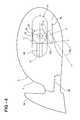
- FIG. 1a partial view of an adjustable light of an exterior rearview mirror according to the invention
- FIG. 2a partial cut view and a partial perspective view of an adjustable light, comprising an adjustment device and a drive within the exterior rearview mirror according to the invention
- FIG. 3another embodiment of the rearview mirror according to the invention in an illustration according to FIG. 2 ;
- FIG. 4another embodiment of an exterior rearview mirror in an illustration according to FIG. 2 ;
- FIG. 5the exterior rearview mirror, according to FIG. 4 , in side view
- FIG. 6a rearview mirror according to the invention in a side view, comprising a light window and a light, which is adjustable according to the opening angle of the light window.
- FIG. 1shows a portion of an adjustable light 10 , which is disposed in an exterior rearview mirror 1 . It comprises a mirror base 30 , by which it is mounted to the motor vehicle and a mirror head 7 , which can be pivoted relative to the mirror base 30 in and against driving direction. A seam 35 ( FIG. 2 ) extend therebetween.
- the mirror head 7can thus be pivotable relative to the mirror base 30 , herein around one axis in two directions (one axis mirror), or around two different axes (two axis mirror). In an advantageous manner, the mirror head 7 can also be foldable into a parking position, where it abuts to the side of the motor vehicle.
- the mirror head 7comprises a housing 2 , in which a mirror glass is housed, which is adjustable in a known manner by means of a drive.
- the housing 2has a light cavity 4 , which is separated from a cavity, including the mirror glass, by means of a lateral boundary and an upper boundary 5 , 6 .
- the light cavity 4is closed by a transparent light pane 3 , which is inserted into an opening 8 of the housing 2 , so that it forms a continuous extension of the housing 2 .
- the light 10is disposed in the light cavity 4 , which is pivotable around a horizontal and a vertical axis in the use position of the mirror head 7 .
- a first vertical illumination direction 26FIG. 1
- the light 10illuminates a roadway, laterally adjacent to the vehicle.
- the light 10is pivotable along arrow 29 into a horizontal illumination direction 25 , in which it emits the light in the driving direction of the vehicle. From this position, or from the previous position, the light 10 can be pivoted along arrow 28 into a lateral illumination direction 27 , so that adjacent vehicles or objects, like e.g. a garage wall, can be illuminated.
- the light 10can also assume any intermediate position, so that it is usable e.g. as a position light with a slightly slanted radiation angle.
- the light pane 3is provided so that the light emitted by the light 10 goes outside in any pivot position.
- Pivoting the light 10 into the three major light emission directions 25 through 27is accomplished through a double articulated support of the light 10 at a respective adjustment mechanism.
- a light support 20reaches through the lateral boundary 6 of the light cavity 4 , wherein said light support is preferably provided cylindrical ( FIG. 1 ) and rotatable around its longitudinal axis 21 .
- the rotation axis 21is disposed horizontal in the use position.
- the light support 20is provided as a hollow body, in which a pushrod 22 is guided. It is supported at one end by an articulated joint 16 at an articulated joint flange 15 , which is mounted to the exterior of the light 10 .
- a support arm 12connects to the front face of the light support 20 , wherein said support arm is elbowed, so that it is connected through an articulated joint 14 with a joint flange 13 at the light 10 .
- the two axes of the articulated joints 14 , 16are located in parallel with each other, offset relative to each other by 90° with reference to the light 10 .
- the light 10has a tubular light housing 11 , in which a reflector 24 is housed.
- a reflector 24In the focal point of the reflector 24 , there is an illuminant 23 , which can be provided as a glow bulb, LED, or similar.
- the illumination direction of the light 10points vertically downward. If the light 10 is to be pivoted so that it emits its light forward in driving direction of the motor vehicle, the light support 20 is rotated around its axis 21 accordingly. Herein, the support arm 12 and the pushrod 22 pivot by the same angle, so that the light housing 11 is moved along accordingly. If the light 10 is to emit light in the lateral direction 27 (open FIG. 1 ), the pushrod 22 is moved in a direction towards the light 10 . Thus, the light housing 11 pivots around the articulating joint 14 , mounted in a rear portion. According to the linear travel of the pushrod 22 , multiple angular positions can be assumed. Certainly, the light cavity 4 with the light pane 3 can be provided, so that also a light emission direction opposite to the driving direction can be facilitated.
- the light 10can be used as a day running light. In this position, and in intermediary positions, the light 10 can serve as position light. In case of a substantially lateral light emission direction 27 , objects or obstacles, disposed next to the motor vehicle, can be illuminated as discussed. Such a side illumination can also be used as an additional aide when parking the vehicle.
- the light functionas a day running light, or position light, different color light can be used when employing a LED as illuminant 23 .
- the light 10is also suitable as a doorstep light, or for lateral roadway illumination in the door area.
- the light 10can be used e.g. for illuminating the door handle.
- this light functioncan be used e.g. in risk situations, or emergencies as an additional warning light.
- FIG. 2shows an adjustable light 10 with the associated adjustment device and a drive within the mirror head 7 .
- the light 10is disposed in the light cavity 4 and comprises the tubular light housing 11 with the reflector 24 , in whose focus the illuminant 23 is disposed.
- the light support 20holds the light 10 by means of the support arm 12 , at whose free end the light housing 11 is connected through the articulated joint 14 to its joint flange 13 .
- the one end of the pushrod 22is connected to the joint flange 15 through the articulated joint 16 .
- the pushrod 22is extended from the light support 20 .
- the end of the pushrod 22located in the light support 20 , is connected to a gear rack 51 through an articulated joint 45 .
- the gear rack 51protrudes from the light support 20 and is in engagement with a sprocket 53 of an electric motor 52 . It is disposed outside of the light cavity 4 within the housing 2 of the mirror head 7 . Since the pushrod 22 is connected on the light side through the articulated joint 16 to the light housing 11 , and on the gear rack side through the articulated joint 45 to the gear rack 51 , a seizing of the light 10 or of the light housing 11 is avoided.
- the gear rack 51is guided by guides 50 outside of the light support 20 , which are provided in the housing 2 of the mirror head 7 .
- the pushrod 22When the gear rack 51 is moved towards the light 10 , the pushrod 22 can assume a slanted position, adapted to the pivoting movement of the light 10 .
- the articulating joint 45is preferably provided as a ball joint.
- the entire drive unitcomprised of gear rack 51 and electrical motor 52 and the guides 50 for the gear rack 51 can remain in its installed position, through the use of a ball joint. Otherwise, when pivoting the light 10 in driving direction, the pushrod 22 , the gear rack 51 , the guides 50 , and the drive motor 52 with the drive sprocket 53 would have to jointly perform the linear movement.
- the light support 20is rotatably supported in the lateral boundary 6 of the light cavity 4 .
- the light support 20is provided with a flange 41 , which has a teething 40 at its enveloping surface 42 . It engages with the teething of a drive sprocket 39 , which is connected through a drive shaft 38 with an electric motor 37 , which is disposed in the housing 2 of the mirror head 7 , outside of the light cavity 4 .
- Both electric motors 37 , 52can be controlled simultaneously, so that the light 10 can perform a combined movement through the pivoting of the light support 20 , and through the linear movement of the gear rack 51 .
- any amount of intermediary positionscan be adjusted according to the permissible pivot angles of the light 10 .
- Such a combination of the movementsis of interest, when the exterior rearview mirror is e.g. pivoted from an operating position into a parking position.
- the position change of the exterior rearview mirrorfor example, when the light 10 is used as a position light, to perform respective corrections of the light position.
- Another, not illustrated, cost effective mounting of the light 10comprises connecting the articulating joint 14 of the light integrally through a film joint with the support arm 12 .
- the gear rack 51 and the pushrod 22can be integrally provided as one component and connected to the light through a film joint, which is integrally formed during the manufacturing process.
- the provision of the light housing 11 and of the joints 14 , 16 , and also of the gear rack 51 and the light support 20 from plasticis advantageous.
- the gear rack 51can be provided elastically deformable.
- the gear rack 51is elastically bent during a lateral pivoting of the light 10 , whereby a seizing during lateral pivoting of the light is avoided.
- FIG. 3shows a light 10 with an adjustable reflector 62 and associated adjustment device.
- a holder arm 71 for an illuminant holder 70 for receiving the illuminant 23protrudes laterally into the light cavity 4 .
- the holder arm 71is advantageously integrally formed with the confinement 6 and/or the light holder 70 .
- the illuminant 23is not pivoted. It is connected through the holder arm 71 and the illuminant holder 70 in a solid manner to the lateral confinement 6 , and thus to the mirror housing 2 .
- the reflector 62is pivotable around the horizontal axis 21 .
- the reflector 62is mounted with its end facing the side of the vehicle to a cylindrical reflector support 61 , whose longitudinal axis forms the rotation axis 21 .
- the reflector support 61is supported in the lateral confinement 6 in a support 60 .
- the end of the reflector support 61protruding from the light cavity 4 , carries a gear 67 , meshing with a drive sprocket 66 of a drive shaft 65 of an electric motor 64 , electrically connected to the vehicle power via electrical connection 63 .
- the reflector support 61can be rotated through the gear drive 66 , 67 around the axis 21 .
- the reflector 62is pivoted accordingly.
- the light generated by the illuminant 23can only be directed in vertical direction, but not in lateral direction.
- the light 10 according to FIG. 3can be produced in a very simple and cost effective manner. It can illuminate the roadway area surrounding the vehicle, and it can also be used as a position light, or as a day running light.
- the exterior rearview mirror 1is provided with two light windows 77 , 78 and a light 10 , adjustable between them. It comprises the cylindrical housing 11 according to FIGS. 1 and 2 . In the housing 11 , the reflector 24 and the illuminant 23 are disposed. The housing 11 is provided at the light support 20 , which is rotatable around the horizontal axis 21 , pointing substantially towards the side of the vehicle. The illuminant support 20 extends from the light housing 11 , substantially horizontal in the direction towards the mirror base 30 . Since the light housing 11 is only rotatable around the horizontal axis 21 , a lateral adjustment of the light 10 is not possible.
- the light support 20 and the light 10are advantageously provided integrally in one piece, wherein the light support is pivotably supported in the mirror housing 2 .
- the light 10is only in operation, when the light is located in the radiation direction of one of the light windows 77 , 78 , illustrated in FIG. 4 .
- the light beams 76generated by the illuminant 23 , are emitted to the outside by the reflector through the light windows 77 , 78 .
- the light housing 11When the light housing 11 is pivoted, so that its longitudinal axis is disposed in the driving direction of the motor vehicle (solid lines in FIG. 4 ), then the light is only emitted through the light window 77 .
- the light housing 12When the light housing 12 is pivoted downward around the axis 21 , the light passes through the light window 78 to the outside. Since the light window 77 is provided in the rear wall of the mirror housing 2 , the light is emitted forward in driving direction.
- the light window 78is disposed approximately at the lower rim of the mirror housing 2 . The exiting light passes through it downward onto the ground in the area next to the motor vehicle.
- the light 10When the light 10 is pivoted from the horizontal illumination position of the light window 77 into the lower position of the light window 78 , no light is passed to the outside in the transition area between both light windows 77 , 78 .
- Thiscan e.g. be accomplished through the mirror housing 2 being comprised of a nontransparent material, only translucent in the area of the light windows 77 , 78 , according to the size and shape of the light windows.
- the remaining mirror housing 2can be provided with a non translucent surface coating.
- cutouts for receiving fitted light panes of the light windows 77 , 78are provided in the non translucent mirror housing 2 . In FIG. 5 , the two described positions of the light 10 are illustrated.
- a light permeable light pane 80is provided, comprising the entire pivot range of the light 10 . It is provided relatively large and in one piece and has the advantage that light from the light 10 can also get to the outside in intermediary positions. Thus, the light 10 can be adjusted, e.g. when the mirror head 7 is in parking position, so that the light is emitted through the light pane 80 , downward onto the area next to the motor vehicle.
Landscapes
- Engineering & Computer Science (AREA)
- Mechanical Engineering (AREA)
- Multimedia (AREA)
- Lighting Device Outwards From Vehicle And Optical Signal (AREA)
Abstract
Description
Claims (9)
Applications Claiming Priority (3)
| Application Number | Priority Date | Filing Date | Title |
|---|---|---|---|
| DE102006056069.8 | 2006-11-20 | ||
| DE102006056069ADE102006056069A1 (en) | 2006-11-20 | 2006-11-20 | Exterior rearview mirror for vehicles, preferably for motor vehicles |
| DE102006056069 | 2006-11-20 |
Publications (2)
| Publication Number | Publication Date |
|---|---|
| US20080174893A1 US20080174893A1 (en) | 2008-07-24 |
| US7771063B2true US7771063B2 (en) | 2010-08-10 |
Family
ID=39004886
Family Applications (1)
| Application Number | Title | Priority Date | Filing Date |
|---|---|---|---|
| US11/941,107Active2028-01-31US7771063B2 (en) | 2006-11-20 | 2007-11-16 | Exterior rearview mirror for vehicles, preferably for motor vehicles |
Country Status (3)
| Country | Link |
|---|---|
| US (1) | US7771063B2 (en) |
| EP (1) | EP1923266B1 (en) |
| DE (2) | DE102006056069A1 (en) |
Cited By (1)
| Publication number | Priority date | Publication date | Assignee | Title |
|---|---|---|---|---|
| US10953788B2 (en) | 2016-05-21 | 2021-03-23 | JST Performance, LLC | Method and apparatus for vehicular light fixtures |
Families Citing this family (8)
| Publication number | Priority date | Publication date | Assignee | Title |
|---|---|---|---|---|
| DE202015105115U1 (en) | 2015-09-28 | 2016-12-30 | SMR Patents S.à.r.l. | Lighting unit and rearview mirror for vehicles |
| CN105882536B (en)* | 2016-06-30 | 2018-02-06 | 山东文捷智能动力有限公司 | Rearview mirror steering assistance illuminator |
| DE102017123830A1 (en) | 2017-10-13 | 2019-04-18 | Dr. Ing. H.C. F. Porsche Aktiengesellschaft | Lighting arrangement for an exterior mirror |
| DE102019203154B4 (en) | 2018-03-08 | 2022-05-12 | Magna Mirrors Holding Gmbh | exterior mirror arrangement |
| EP4051539B1 (en)* | 2019-10-31 | 2023-10-18 | Gentex Corporation | Rotatable outside mirror with imager assembly |
| CN112644366B (en)* | 2021-01-07 | 2022-06-28 | 恒大恒驰新能源汽车研究院(上海)有限公司 | Ground lamp device of automobile rearview mirror |
| KR20220169125A (en)* | 2021-06-18 | 2022-12-27 | 에스엘 주식회사 | Lighting device |
| DE102024201347B3 (en) | 2024-02-14 | 2024-12-19 | Magna Mirrors Holding Gmbh | lighting unit of a vehicle exterior mirror |
Citations (24)
| Publication number | Priority date | Publication date | Assignee | Title |
|---|---|---|---|---|
| US1499640A (en)* | 1921-11-16 | 1924-07-01 | Lucius D Copeland | Dirigible lamp |
| US2595331A (en)* | 1950-01-30 | 1952-05-06 | Paul F Calihan | Combination vision mirror and signaling device |
| US4112486A (en)* | 1976-05-26 | 1978-09-05 | Murray Tovi Designs, Inc. | Remotely controlled positioning device for illuminating unit and the like |
| US4353110A (en)* | 1980-09-12 | 1982-10-05 | Ellis Richard D | Search and warning light system |
| US4809137A (en)* | 1987-07-24 | 1989-02-28 | Kiyoshi Yamada | Back-mirror fitted with illumination light at car side |
| US4916430A (en) | 1988-11-03 | 1990-04-10 | Vu Thuan D | Back up rear view mirror light |
| JPH0350044A (en)* | 1989-04-10 | 1991-03-04 | Stanley Electric Co Ltd | Backing light for automobile |
| US5089314A (en) | 1987-02-25 | 1992-02-18 | Tdk Corporation | Carrier tape for electronic circuit elements and method of manufacturing an electronic circuit element series |
| US5497306A (en) | 1993-02-01 | 1996-03-05 | Donnelly Corporation | Exterior vehicle security light |
| US5669698A (en)* | 1995-05-24 | 1997-09-23 | Veldman; Roger L. | Modular rearview mirror assembly and method for making same |
| US5774283A (en)* | 1995-10-18 | 1998-06-30 | Reitter & Schefenacker Gmbh & Co. Kg | Exterior rearview mirror for vehicles, especially for motor vehicles |
| US5851064A (en)* | 1995-11-07 | 1998-12-22 | Whelen Engineering Company, Inc. | Integrated warning light and rear-view mirror |
| US5892438A (en) | 1998-04-02 | 1999-04-06 | Vaughn; Roman M. | Side rear view mirror spotlight device |
| US5938322A (en)* | 1998-08-19 | 1999-08-17 | Whelen Engineering Company, Inc. | Rear-view mirror with forward facing warning light |
| US5938320A (en) | 1997-03-19 | 1999-08-17 | Harman Automotive, Inc. | Enhanced illuminated polymeric indicator employed in a mirror housing of an automotive vehicle |
| US6039448A (en)* | 1998-10-01 | 2000-03-21 | Oprea; Florin I. | Side rearview mirror device |
| US6049271A (en)* | 1999-06-29 | 2000-04-11 | Chu; Ching-Ti | Vehicle rearview mirror with multiple signal means |
| US6250784B1 (en)* | 1998-07-14 | 2001-06-26 | Yasuhiro Kawasaki | Vehicular wing mirror having a light-transmitting housing |
| WO2001059734A1 (en) | 2000-02-11 | 2001-08-16 | Britax Vision Systems (North America) Inc. | Exterior mirror |
| US6568839B1 (en)* | 1993-02-01 | 2003-05-27 | Donnelly Corporation | Vehicle exterior mirror system with signal light |
| US20030193815A1 (en)* | 2002-04-11 | 2003-10-16 | Esam Co., Ltd. | Side mirror cover and cover lamp to be used therefor |
| US20040190303A1 (en)* | 2003-03-26 | 2004-09-30 | Kazuharu Mishimagi | Side mirror cover and side mirror body |
| DE10338797A1 (en) | 2003-08-23 | 2005-03-17 | Schefenacker Vision Systems Germany Gmbh & Co. Kg | Exterior mirror for motor vehicles, comprises a light which is fixed on an intermediate member, which in turn is arranged between the mirror foot and the mirror head |
| US7121701B2 (en)* | 2004-10-21 | 2006-10-17 | An Sheng Liu | Extra rear-view mirror for a vehicle |
- 2006
- 2006-11-20DEDE102006056069Apatent/DE102006056069A1/ennot_activeWithdrawn
- 2007
- 2007-11-13DEDE502007001720Tpatent/DE502007001720D1/enactiveActive
- 2007-11-13EPEP07022000Apatent/EP1923266B1/enactiveActive
- 2007-11-16USUS11/941,107patent/US7771063B2/enactiveActive
Patent Citations (24)
| Publication number | Priority date | Publication date | Assignee | Title |
|---|---|---|---|---|
| US1499640A (en)* | 1921-11-16 | 1924-07-01 | Lucius D Copeland | Dirigible lamp |
| US2595331A (en)* | 1950-01-30 | 1952-05-06 | Paul F Calihan | Combination vision mirror and signaling device |
| US4112486A (en)* | 1976-05-26 | 1978-09-05 | Murray Tovi Designs, Inc. | Remotely controlled positioning device for illuminating unit and the like |
| US4353110A (en)* | 1980-09-12 | 1982-10-05 | Ellis Richard D | Search and warning light system |
| US5089314A (en) | 1987-02-25 | 1992-02-18 | Tdk Corporation | Carrier tape for electronic circuit elements and method of manufacturing an electronic circuit element series |
| US4809137A (en)* | 1987-07-24 | 1989-02-28 | Kiyoshi Yamada | Back-mirror fitted with illumination light at car side |
| US4916430A (en) | 1988-11-03 | 1990-04-10 | Vu Thuan D | Back up rear view mirror light |
| JPH0350044A (en)* | 1989-04-10 | 1991-03-04 | Stanley Electric Co Ltd | Backing light for automobile |
| US5497306A (en) | 1993-02-01 | 1996-03-05 | Donnelly Corporation | Exterior vehicle security light |
| US6568839B1 (en)* | 1993-02-01 | 2003-05-27 | Donnelly Corporation | Vehicle exterior mirror system with signal light |
| US5669698A (en)* | 1995-05-24 | 1997-09-23 | Veldman; Roger L. | Modular rearview mirror assembly and method for making same |
| US5774283A (en)* | 1995-10-18 | 1998-06-30 | Reitter & Schefenacker Gmbh & Co. Kg | Exterior rearview mirror for vehicles, especially for motor vehicles |
| US5851064A (en)* | 1995-11-07 | 1998-12-22 | Whelen Engineering Company, Inc. | Integrated warning light and rear-view mirror |
| US5938320A (en) | 1997-03-19 | 1999-08-17 | Harman Automotive, Inc. | Enhanced illuminated polymeric indicator employed in a mirror housing of an automotive vehicle |
| US5892438A (en) | 1998-04-02 | 1999-04-06 | Vaughn; Roman M. | Side rear view mirror spotlight device |
| US6250784B1 (en)* | 1998-07-14 | 2001-06-26 | Yasuhiro Kawasaki | Vehicular wing mirror having a light-transmitting housing |
| US5938322A (en)* | 1998-08-19 | 1999-08-17 | Whelen Engineering Company, Inc. | Rear-view mirror with forward facing warning light |
| US6039448A (en)* | 1998-10-01 | 2000-03-21 | Oprea; Florin I. | Side rearview mirror device |
| US6049271A (en)* | 1999-06-29 | 2000-04-11 | Chu; Ching-Ti | Vehicle rearview mirror with multiple signal means |
| WO2001059734A1 (en) | 2000-02-11 | 2001-08-16 | Britax Vision Systems (North America) Inc. | Exterior mirror |
| US20030193815A1 (en)* | 2002-04-11 | 2003-10-16 | Esam Co., Ltd. | Side mirror cover and cover lamp to be used therefor |
| US20040190303A1 (en)* | 2003-03-26 | 2004-09-30 | Kazuharu Mishimagi | Side mirror cover and side mirror body |
| DE10338797A1 (en) | 2003-08-23 | 2005-03-17 | Schefenacker Vision Systems Germany Gmbh & Co. Kg | Exterior mirror for motor vehicles, comprises a light which is fixed on an intermediate member, which in turn is arranged between the mirror foot and the mirror head |
| US7121701B2 (en)* | 2004-10-21 | 2006-10-17 | An Sheng Liu | Extra rear-view mirror for a vehicle |
Non-Patent Citations (1)
| Title |
|---|
| European Search Report for EP 07022000; Feb. 12, 2008. |
Cited By (2)
| Publication number | Priority date | Publication date | Assignee | Title |
|---|---|---|---|---|
| US10953788B2 (en) | 2016-05-21 | 2021-03-23 | JST Performance, LLC | Method and apparatus for vehicular light fixtures |
| US12351101B1 (en) | 2016-05-21 | 2025-07-08 | JST Performance, LLC | Method and apparatus for vehicular light fixtures |
Also Published As
| Publication number | Publication date |
|---|---|
| US20080174893A1 (en) | 2008-07-24 |
| EP1923266A1 (en) | 2008-05-21 |
| DE102006056069A1 (en) | 2008-05-21 |
| EP1923266B1 (en) | 2009-10-14 |
| DE502007001720D1 (en) | 2009-11-26 |
Similar Documents
| Publication | Publication Date | Title |
|---|---|---|
| US7771063B2 (en) | Exterior rearview mirror for vehicles, preferably for motor vehicles | |
| US6511192B1 (en) | Side view mirror with integral lighting | |
| EP2119595B1 (en) | Turn-indicator light module for a vehicle mirror assembly and vehicle mirror assembly comprising a turn-indicator light module | |
| US5774283A (en) | Exterior rearview mirror for vehicles, especially for motor vehicles | |
| US6926431B1 (en) | Vehicular mirror assembly incorporating multifunctional illumination source | |
| EP1547864B1 (en) | Vehicle mirror assembly that includes light unit | |
| US10926704B2 (en) | Exterior rearview mirror with constant ground illumination | |
| CN111511603B (en) | central swing area | |
| EP1445149A1 (en) | Outer mirror | |
| US7052165B2 (en) | Vehicle headlight assembly | |
| US11338725B2 (en) | Vehicular tailgate illumination system with adjustably positioned illumination device | |
| US5539625A (en) | Vehicle headlamp aiming device | |
| JPH0350044A (en) | Backing light for automobile | |
| CA2003685C (en) | Retractable headlamp assembly | |
| US11518310B2 (en) | Lighting device, rear-view device and motor vehicle | |
| JPH01309838A (en) | Lighting fixture for vehicle | |
| CN217540605U (en) | Vehicle lamp, vehicle and vehicle headlamp | |
| JP2004330906A (en) | Vehicle headlights | |
| JP3499679B2 (en) | Car rearview mirror | |
| JP2006111128A (en) | Outside mirror device for vehicle | |
| WO2024161514A1 (en) | Vehicular imaging device | |
| CN115854284A (en) | Shine floor-lamp and vehicle rearview mirror | |
| JP4353062B2 (en) | Outside mirror device for vehicle | |
| KR100231665B1 (en) | Headlamp assembly of car with adjustable horizontal angle | |
| CN117480340A (en) | Multiband adjustable lamp |
Legal Events
| Date | Code | Title | Description |
|---|---|---|---|
| AS | Assignment | Owner name:SCHEFENACKER PATENTS S.A.R.L., LUXEMBOURG Free format text:ASSIGNMENT OF ASSIGNORS INTEREST;ASSIGNORS:LIESENER, ALF;BRACHT, GERNOT MICHAEL;REEL/FRAME:020460/0356;SIGNING DATES FROM 20071115 TO 20080122 Owner name:SCHEFENACKER PATENTS S.A.R.L., LUXEMBOURG Free format text:ASSIGNMENT OF ASSIGNORS INTEREST;ASSIGNORS:LIESENER, ALF;BRACHT, GERNOT MICHAEL;SIGNING DATES FROM 20071115 TO 20080122;REEL/FRAME:020460/0356 | |
| AS | Assignment | Owner name:VISIOCORP PATENTS S.A.R.L., LUXEMBOURG Free format text:CHANGE OF NAME;ASSIGNOR:SCHEFENACKER PATENTS S.A.R.L.;REEL/FRAME:020596/0701 Effective date:20071205 | |
| FEPP | Fee payment procedure | Free format text:PAYOR NUMBER ASSIGNED (ORIGINAL EVENT CODE: ASPN); ENTITY STATUS OF PATENT OWNER: LARGE ENTITY | |
| AS | Assignment | Owner name:SMR PATENTS S.A.R.L.,LUXEMBOURG Free format text:CHANGE OF NAME;ASSIGNOR:VISIOCORP PATENTS S.A.R.L.;REEL/FRAME:024433/0772 Effective date:20090824 Owner name:SMR PATENTS S.A.R.L., LUXEMBOURG Free format text:CHANGE OF NAME;ASSIGNOR:VISIOCORP PATENTS S.A.R.L.;REEL/FRAME:024433/0772 Effective date:20090824 | |
| STCF | Information on status: patent grant | Free format text:PATENTED CASE | |
| FPAY | Fee payment | Year of fee payment:4 | |
| MAFP | Maintenance fee payment | Free format text:PAYMENT OF MAINTENANCE FEE, 8TH YEAR, LARGE ENTITY (ORIGINAL EVENT CODE: M1552) Year of fee payment:8 | |
| MAFP | Maintenance fee payment | Free format text:PAYMENT OF MAINTENANCE FEE, 12TH YEAR, LARGE ENTITY (ORIGINAL EVENT CODE: M1553); ENTITY STATUS OF PATENT OWNER: LARGE ENTITY Year of fee payment:12 |