US7769265B2 - Apparatus and method for managing flexible elongate elements - Google Patents
Apparatus and method for managing flexible elongate elementsDownload PDFInfo
- Publication number
- US7769265B2 US7769265B2US11/769,911US76991107AUS7769265B2US 7769265 B2US7769265 B2US 7769265B2US 76991107 AUS76991107 AUS 76991107AUS 7769265 B2US7769265 B2US 7769265B2
- Authority
- US
- United States
- Prior art keywords
- track
- spool
- fiber
- winding
- length
- Prior art date
- Legal status (The legal status is an assumption and is not a legal conclusion. Google has not performed a legal analysis and makes no representation as to the accuracy of the status listed.)
- Expired - Fee Related, expires
Links
Images


Classifications
- B—PERFORMING OPERATIONS; TRANSPORTING
- B65—CONVEYING; PACKING; STORING; HANDLING THIN OR FILAMENTARY MATERIAL
- B65H—HANDLING THIN OR FILAMENTARY MATERIAL, e.g. SHEETS, WEBS, CABLES
- B65H75/00—Storing webs, tapes, or filamentary material, e.g. on reels
- B65H75/02—Cores, formers, supports, or holders for coiled, wound, or folded material, e.g. reels, spindles, bobbins, cop tubes, cans, mandrels or chucks
- B65H75/18—Constructional details
- B—PERFORMING OPERATIONS; TRANSPORTING
- B65—CONVEYING; PACKING; STORING; HANDLING THIN OR FILAMENTARY MATERIAL
- B65H—HANDLING THIN OR FILAMENTARY MATERIAL, e.g. SHEETS, WEBS, CABLES
- B65H55/00—Wound packages of filamentary material
- B65H55/04—Wound packages of filamentary material characterised by method of winding
- G—PHYSICS
- G02—OPTICS
- G02B—OPTICAL ELEMENTS, SYSTEMS OR APPARATUS
- G02B6/00—Light guides; Structural details of arrangements comprising light guides and other optical elements, e.g. couplings
- G02B6/44—Mechanical structures for providing tensile strength and external protection for fibres, e.g. optical transmission cables
- G02B6/4439—Auxiliary devices
- G02B6/4457—Bobbins; Reels
Definitions
- the present inventionrelates to an apparatus and method for managing flexible lines or flexible elongate elements such as a wire, tube, individual fiber, ribbon fiber, or cable with fixed ends.
- Fiberis also susceptible to optical measurement losses or shortened life if it is wound to a radius smaller than the minimum fiber bend radius. It is known to wind fiber in a figure eight pattern, relieving the torque as you wind first in one direction then in the other.
- One known fiber management systemis two spaced, coplanar spools between the fixed fiber ends. Fiber is wound in a figure eight pattern on the spools, while maintaining a radius greater than the minimum fiber bend radius. The two side-by-side spools take up additional space between the optical devices.
- Embodiments described hereinprovide for an apparatus and method for managing flexible lines or flexible elongate elements between fixed ends or points in the line to handle any slack in the line between the fixed ends.
- an apparatus for managing flexible lineswhich comprises a spool having an outwardly directed winding track or race of predetermined width, first and second side regions extending around opposite sides of the track and a central region between the side regions, the first and second side regions receiving alternating, successive windings of a flexible line with the flexible line crossing over from one side region to the other side region between successive windings at the central region of the track, such that a folded figure eight pattern is formed.
- At least one guide memberprojects radially outwards from the central region of the track as a guide for windings about the opposite side regions. In other embodiments, no guide member is used.
- the track widthis at least equal to two times the width of the ribbon fiber plus the width of the guide member, so that alternate turns of the ribbon fiber can be wound around the two side regions of the winding track on opposite sides of the guide member.
- the spoolhas a pair of spaced rims extending around opposite sides of the winding track or race in order to help hold windings of a flexible line or flexible elongate element on the track.
- the guide membermay be fixed or removably mounted on the track, and acts as a guide as a flexible elongate element is wound around the track first in a path around one side of the guide member and then in a path around the other side of the guide member.
- the guide memberis a stand-off clip which may be integrally formed on the track or may be removably mounted in a slot provided at the center of the track.
- the apparatusmay further comprise a mounting device for holding the spool.
- the mounting devicemay be a base having at least one mounting recess or slot, and the outer end of the stand-off clip may be adapted for releasable engagement in the mounting recess or slot.
- the stand-off clipin this case mounts the spool on the base, and also acts as both a guide for alternate side windings of the flexible elongate element and as a stand-off which spaces the spool above the base to provide space for winding purposes.
- the spoolmay have a central axial opening and the mounting device may be a mounting base and a hub extending from one face of the base which extends through the opening in the spool.
- the guide membermay be an integral projection or bump formed at the center of the track, or may be a separate guide member removably mounted in the track.
- the apparatusmay be used to manage any type of flexible elongate line or element, such as optical fibers, electrical wires, cables, ropes, flexible tubes or hoses, threads, or the like, with suitable adjustment of the winding track width and diameter on each spool.
- the material of the spoolmay also be varied, depending on the material of elongate line to be managed.
- a method of managing a length of a flexible, elongate element extending between two fixed endscomprises positioning a spool between the fixed ends of the elongate element, the spool having an outwardly facing winding track for receiving alternate windings of the elongate element on first and second side regions of the track, winding a first turn of the elongate element around the first side region of the track, crossing the elongate element over to the second side region of the track in a cross over area and winding a second turn of the elongate element around the second side region of the track, crossing the elongate element back over to the first side region of the track at the cross over area, and repeating the preceding four steps until at least the majority of the slack in the length of the elongate element between the fixed ends is taken up.
- a method of splicing fibers or the like to extend between two fiber optic devices and managing excess length of fiber between the devices after splicingcomprises adjusting the lengths of the fiber pigtails extending from each device such that the total pigtail length is a selected length based on the distance between each device and a spool race or track around which the spliced fiber is to be wound, and n times the spool track circumference, where n is an integer, splicing the fiber pigtails together, winding the length of spliced fiber in a first turn about a first side region of the track, crossing the fiber over to the second side region of the track, winding a second turn about the second side region of the track, crossing the fiber back to the first side region of the track, and repeating the preceding four steps until at least the majority of the slack in the spliced fiber between the devices is taken up.
- the spliced fiberis wound in a generally folded figure eight pattern, but about a single winding spool. This technique results in cancellation of twists in the fiber which would otherwise occur if a fiber was wound straight around the spool with each turn lying directly over the preceding turn. If the fiber is a ribbon fiber, this winding method helps to keep the ribbon fiber substantially flat on the spool and reduces torque as a result of twist in the ribbon fiber.
- FIG. 1is a perspective view of a prior art fiber management apparatus positioned between two fiber optic devices
- FIG. 2is a perspective view of a fiber management apparatus according to a first embodiment positioned between two fiber optic devices;
- FIG. 3is a perspective view of the fiber management apparatus of FIG. 2 prior to installation, with part of the base broken away;
- FIG. 4is a perspective exploded view similar to FIG. 3 but illustrating the parts of the apparatus separated from one another;
- FIG. 5is a perspective view similar to FIG. 3 illustrating several spools positioned on the mounting device
- FIG. 6Ais a perspective, schematic view illustrating winding of a first turn of a fiber onto the device of FIG. 3 ;
- FIG. 6Bis a left side elevation view of the spool at the winding stage of FIG. 6A ;
- FIG. 6Cis a right side elevation view of the spool at the winding stage of FIG. 6A ;
- FIG. 7Ais a perspective view similar to FIG. 6A illustrating winding of a second turn of a fiber onto the spool;
- FIG. 7Bis a left side elevation view of the spool at the winding stage of FIG. 7A ;
- FIG. 7Cis a right side elevation view of the spool at the winding stage of FIG. 7A ;
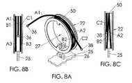
- FIG. 8Ais a perspective, schematic view similar to FIGS. 6A and 7A illustrating a fully managed condition
- FIG. 8Bis a left side elevation view of the spool at the winding stage of FIG. 8A ;
- FIG. 8Cis a right side elevation view of the spool at the winding stage of FIG. 8A ;
- FIG. 9is a schematic front elevation view of the fiber management apparatus of FIGS. 2 to 8 positioned between two fixed fiber points at two fiber optic devices, illustrating parameters for calculating a desired total spliced fiber length prior to splicing and winding of the fiber;
- FIG. 10is a perspective view of a modified spool
- FIG. 11is a perspective view of another modified spool
- FIG. 12is a perspective view of an alternative mounting device.
- FIG. 13is a perspective view illustrating the spools of any of the preceding embodiments mounted on the mounting device of FIG. 12 .
- Certain embodiments as disclosed hereinprovide for an apparatus and method for managing flexible lines or flexible elongate elements having fixed ends.
- one apparatus and method as disclosed hereinallows for managing excess of fiber between fixed ends or points on the fiber produced when terminating various devices to optical fiber cables.
- an apparatus and method for managing fiberssuch as optical fibers are described, but the described apparatus and methods may alternatively be used for managing other types of flexible line or flexible elongate elements, such as electrical or other flexible wires, cables, ropes, flexible tubes or hoses, threads, or the like.
- the fibermay be one or more individual optical fibers or a ribbonized fiber (ribbon fiber). Ribbon fiber contains multiple fibers in a ribbon-like form.
- the management apparatus and methods for flexible elongate elements or lines other than fibersmay be identical to those described in the embodiments below, with appropriate adjustment of the scale and material of the apparatus to accommodate flexible elongate elements of different sizes and materials.
- spoolas used in this application means a device on which a flexible elongate element can be wound or spooled.
- spools illustrated in the drawings and described beloware round, in other embodiments the spools may have other continuous loop shapes such as elliptical, oval, polygonal, or the like.
- FIG. 1illustrates a prior art fiber management apparatus 10 comprising two spools 12 , 13 positioned in a side-by-side, coplanar arrangement and secured to a stand-off rod 14 between two fiber optic devices 16 , 18 such as a connector shell and a cable termination housing.
- two fiber optic devices 16 , 18such as a connector shell and a cable termination housing.
- Excess of fiber, after the fiber pigtails from each device have been spliced,is managed by winding in a figure eight pattern around the two spools 12 , 13 . It can be seen that this arrangement takes up a significant amount of space.
- FIGS. 3 , 4 and 6 to 9illustrate one embodiment of a fiber management apparatus 20 for managing an optical fiber
- FIG. 2illustrates the apparatus 20 mounted between two fiber optic devices 16 , 18 .
- the apparatus 20includes a winding device comprising single spool 22 having a race or track 24 onto which fiber can be wound and a guide member 25 projecting radially outwardly from a central region of the track.
- the apparatus 20further comprises a base or mounting device 26 on which the winding device is mounted.
- the guide memberacts as an aid for spooling fiber on the track, as described in more detail below, and in the illustrated embodiment also acts as a mounting attachment to the base.
- the guide member 25may act only as a guide and not as a mounting attachment, and may be eliminated altogether in other embodiments.
- the base 26may be secured between two fiber optic devices 16 , 18 , such as a connector shell and a cable termination housing, so that the spool 22 is positioned between the end faces of the devices and can be used to take up any slack in spliced fibers extending between the devices.
- the base 26is shown with broken away edges since the outer peripheral shape and dimensions of the base are dependent on the actual installation, and may be varied in different embodiments.
- Base 26may be a base plate or platform of rectangular, round, or other shapes.
- the guide member 25comprises a stand-off clip which has opposite end portions designed for releasable engagement with the spool 22 and base 26 respectively, as explained in more detail below.
- the stand-off clipis engaged with the base 26 and spool 22 , as in FIG. 3 , the spool is raised above the base 26 to allow winding of an elongate element about the spool, as described in more detail below in connection with FIGS. 6 to 8 .
- the stand-off clipmay be secured to the spool at one end or may be integrally formed with the spool, as described in more detail below in connection with FIGS. 10 and 11 .
- diametrically opposed, outwardly projecting guide membersmay be provided on opposite regions of the track, and in this case the guide members are located at ninety degrees to the stand-off clip location of FIGS. 3 and 4 .
- the guide membermay be eliminated altogether.
- the spoolis hollow and comprises an outer ring with a central opening 27 .
- the winding race or track 24has raised rims 28 , 29 extending around the opposite sides of the race or track 24 to assist in holding fiber on the track.
- the race or trackis of predetermined width based on the width of the fiber, and has a width greater than or substantially equal to at least two times the width of the fiber plus the width of the guide member or stand-off clip 25 , if present.
- the stand-off clipis of sufficient structural strength to support the spool.
- the track widthcan be much less than that of a spool for holding ribbon fiber.
- mounting clip 25has resilient fingers 30 , 31 at its opposite ends for snap engagement in mating slots 32 , 33 in the base and spool, respectively.
- a pair of diametrically opposed projections or guide ribs 34project inwardly from the inner surface of the spool 22 .
- FIGS. 6 to 9One embodiment of a method of winding a fiber such as a ribbon fiber 35 which has fixed or inaccessible ends onto the spool 22 in the apparatus 20 is illustrated schematically in FIGS. 6 to 9 .
- FIG. 9illustrates an initial stage in the fiber management process where the apparatus 20 is positioned between two fixed fiber points 36 , 38 at the exit faces of two fiber optic devices to be connected together.
- fiber pigtails 40 , 42 of variable lengthproject from each optical device housing. These fiber pigtails can be adjusted in length prior to splicing, as described in more detail below. After splicing, the excess fiber is wound onto spool 22 as illustrated in FIGS. 6 to 8 .
- a first turn of fiber 35is wound around one side region of the track 24 adjacent one side rim 29 and on one side of the guide member or stand-off clip 25 , as shown in FIG. 6A .
- This turnis wound following the sequence A 1 , A 2 , A 3 , as illustrated in FIGS. 6A , 6 B, and 6 C.
- the fiberPrior to making the first turn, the fiber enters the spool approximately at the center of track 24 as seen in FIG. 6A , before passing to one side of stand-off clip 25 at the lower end of the spool, as illustrated in FIG. 6C .
- the fiberAfter passing one side of the stand-off clip 25 , the fiber is crossed over at cross-over point 50 to the second side region of the spool (on the opposite side of stand-off clip 25 ) adjacent rim 28 , as illustrated in FIGS. 7A , 7 B and 7 C. A second turn is then wound around the second side region of the spool track in the sequence B 1 , B 2 , B 3 , until it passes the opposite side of stand-off clip 25 . The fiber is then crossed over back to the first side region in the vicinity of point 50 , and continues through turn C 1 , C 2 as indicated in FIGS. 8A , 8 B, and 8 C.
- Additional windings around the first and second side regions of the spoolcan be made in the same way as illustrated in FIGS. 6 to 8 , with the winding continued in this pattern as necessary until at least the majority of the slack in the fiber is taken up.
- This winding methodeffectively winds the fiber in a folded figure eight pattern, and cancels twist on the fiber which would result if successive turns were simply wound one on top of the other without any cross over or alternating between opposite sides of the spool.
- This winding methodas long as there is an even number of turns, there is substantially no twist on the fiber. If there is an odd number of turns, there is about one half turn of twist in the final winding.
- One or more tie wraps, clips, or other holding devicesmay be engaged with the spool in this condition and extend over the winding track to hold the wound fiber in place.
- the side rims 28 , 29may be provided with openings for engaging such holding devices.
- the stand-off clip or guide member 25 at the center of the track or race 24aids in making the alternate route windings around opposite side regions of the track 24 .
- a guide member 25is not essential and may be eliminated in alternative embodiments, with the user simply guiding the fiber in alternate windings around opposite side regions of the track in an equivalent manner, without using a central guide member.
- multiple individual fibersmay be wound on the same spool in the same manner as described above.
- Multiple ribbon fibersmay also be wound on a single spool, depending on the depth of the winding track or race or the height of rims 28 , 29 . In this case, successive ribbon fibers are managed or wound one over the other, as long as the dimensions of the spool are appropriate to accommodate them.
- FIG. 5illustrates a plurality of winding devices mounted on a modified base 46 with the spool openings 27 aligned.
- Base 46has additional clip mounting slots 32 for receiving the end of each stand-off clip 25 to support each spool 22 at a spaced location above the base.
- the apparatusis otherwise identical to the single spool version of FIGS. 2 to 4 , and like reference numbers have been used for like parts as appropriate.
- fibermay be wound on each spool before the associated mounting clip 25 is engaged with base 46 , to allow more space for winding purposes, unlike the single spool version of FIGS. 3 and 4 where fiber may be wound after the spool mounting clip is engaged with the base 26 .
- the windingmay be done sequentially, with a length of a first fiber wound on a first spool and the attached mounting clip then engaged with base 46 , followed by winding a length of a second fiber on a second spool and then attaching the associated mounting clip to the base, and so on until fiber has been wound on all the spools.
- the slots 32 in base 46may be spaced farther apart so that there are spaces between adjacent spools when mounted on the base. This may allow winding of fiber onto each spool after it is mounted on the base. Although three spools are shown mounted on the base 46 in FIG. 5 , the base may be adapted to receive a greater number of spools in alternative embodiments.
- the fiber or flexible elongate element managing apparatus 20takes up only about half of the space of a prior art fiber managing apparatus 10 as illustrated in FIG. 1 , since it has only one spool instead of two side-by-side spools. At the same time, it still allows fiber to be wound in a folded figure eight pattern while introducing little or no torque in the fiber. The space saving can be helpful when such devices have to be installed in an area having only a restricted amount of space.
- the stand-off clip of FIGS. 2 to 5acts as both a guide for winding fiber alternately about opposite sides of the spool winding track or race, and as a stand-off for mounting the spool at a location spaced above a mounting base.
- a method of adjusting the length of fiber to be managed so that it is close to a whole number of turns on the spool 22is described below, with reference to FIG. 9 .
- a fiber pigtail of one or more individual fibers or ribbon fibernormally extends from a housing or enclosure for a fiber optic device such as an optical connector shell or a cable termination housing before the device is connected to another such device in an assembly.
- FIG. 9illustrates a first fiber pigtail 40 projecting from a fixed fiber end or point 36 at a first fiber optic device, and a second fiber pigtail 42 projecting from a fixed fiber end or point 38 at a second fiber optic device.
- the pigtailshave free ends 44 , 45 prior to splicing.
- the length L 1is the pigtail length from the fixed point or end of one of the fibers or ribbon fibers at a first device
- the length L 2is the pigtail length from the fixed point or end of the other fiber or ribbon fiber at a second device
- dis the diameter of the winding track 24 of spool 22 of the fiber management apparatus 20
- l 1 and l 2are the distances on each side of the spool 22 from the fibers' fixed points to the points where the spliced fiber joins the winding track 24 , typically at the apex or uppermost region of the spool.
- the installercan calculate total spliced fiber lengths L corresponding to substantially a whole number of turns on the spool 22 , so that only a small amount of excess fiber is left after winding in the figure eight pattern as described above.
- the integer nmay be an even or odd number.
- nis an odd number, there is one half turn of twist left after winding on the spools.
- the pigtailscan then be cut to appropriate lengths.
- the length L 1 and the length L 2may be different as long as the total of these lengths meets the above relationship, and the installer can appropriately adjust these lengths based on the available pigtail lengths on each side.
- a section of length q ⁇ dwhere q is an integer, which spans the damaged portion may be removed or cut out before re-splicing. If possible, depending on the length of the damaged portion, q is equal to one so as to minimize the discarded fiber. This means that the fiber length after splicing is still approximately equal to a whole number of turns on the spool 22 .
- ribbon fibermay have a predetermined color or insignia on one face which is then arranged to be outermost for each turn on opposite sides of the spool. This helps the operator to avoid unintended twist while winding the ribbon fiber.
- FIGS. 10 and 11illustrate modified winding devices or spools 70 and 80 which may be used in place of spool 22 and stand-off clip 25 of FIGS. 2 to 4 in a modified fiber management apparatus.
- the spool 70 of FIG. 10has an integrally formed guide member or protrusion 71 in the center of the winding track 24 , in place of the removable stand-off clip 25 of the previous embodiment.
- Spool 70is otherwise identical to that of FIGS. 2 to 4 , and like reference numerals have been used for like parts as appropriate.
- the spool 80 of FIG. 11is similar to spool 22 but instead of a removable, double-ended clip 25 as provided with spool 22 , the clip 81 is integrally formed with the spool at the center of winding track 24 at one end and has resilient fingers 30 at its opposite end which may be used for engagement in a slot in a suitable base member 26 , as in the first embodiment.
- the clip 81may be formed separately from the spool and permanently secured to the center of the winding track.
- the spool 80is otherwise identical to spool 22 , and like reference numerals have been used for like parts as appropriate.
- FIG. 12illustrates another embodiment of a mounting device 55 for holding one or more of the spools 22 , 70 or 80 described above.
- the mounting device 55is similar or identical to the folding spool mounting device described in co-pending application Ser. No. 11/757,023 filed on Jun. 1, 2007, the contents of which are incorporated herein by reference.
- the mounting device of FIG. 12comprises a base 56 having a projecting hub 58 for extending through the central opening 27 in a spool.
- the hub 58comprises a four-finger collet having four flexible fingers 60 arranged to grip against the central opening in the spool, with gaps or keyways 62 between each adjacent pair of fingers. A greater or lesser number of fingers may be provided in alternative embodiments.
- a mounting recess 64is provided on the outer surface of each finger 60 .
- FIG. 13illustrates a plurality of spools 22 , 70 or 80 mounted on hub 58 .
- a spool 22 , 70 , or 80is first positioned with opening 27 aligned with hub 58 and projections or guide ribs 34 aligned with keyways 62 , and the central opening 27 is then moved over the hub.
- the projections or guide ribs 34engage in the keyways 62 between adjacent fingers of the hub 58 to restrict rotation of the spool device 20 .
- the fingers 60are urged inwardly as the device 20 is forced over the outer regions of the fingers, and then spring outwardly to grip against the spool opening when the spool is aligned and seated on the mounting recess 64 .
- One or more spoolsmay be mounted on the hub 58 where multiple ribbon fibers or bunches of fibers are to be managed.
- FIG. 13illustrates a stack of three spools 22 , 70 or 80 mounted on the mounting device 55 . A greater or lesser number of spools may be accommodated with suitable adjustment of the length of hub 58 .
- the base 56 of the mounting device 58may have a mounting arrangement for engagement with stand-off rods between two fiber optic devices.
- the base 56has one or more through bores 65 for engagement over stand off rods.
- Other types of stand-off rod engagement mechanismsmay be used in alternative embodiments, such as grooves in the rear face of base 56 , or an attachment clip or the like.
- the fiber winding method using the spools 70 or 80 of FIGS. 10 and 11is the same as illustrated in FIGS. 6 to 8 for the first embodiment and as described above.
- the guide member or projection 71 in FIG. 10 and the clip 81 of FIG. 11act in the same way as stand-off clip 25 of the first embodiment in guiding fiber for winding successive turns of fiber alternately on opposite side regions of winding track 24 .
- Both spool 22 and spool 80may be selectively mounted either on a flat plate or base 26 as in FIGS. 2 to 5 , or on the hub of mounting device 55 , while spool 70 may be selectively mounted on mounting device 55 .
- a spoolhas a projection or guide member located at the center of a winding track to act as a guide for directing alternate windings of a fiber on opposite side regions of the winding track on opposite sides of the guide member.
- the guide memberis a stand-off clip which has the additional function of mounting the spool on a base at a spacing from the base sufficient to allow winding. Fiber enters the winding track approximately at the center of the track, and may enter at a position substantially opposite to the guide member or stand-off clip. It is then directed around one side region of the track on one side of the guide member, and after one turn the fiber crosses over to the opposite side region of the track on the other side of the guide member.
- apparatus 20may be used for managing other types of flexible elongate elements such as electrical wires or cables, steel wires and ropes as used in the construction and elevator industry, hoses such as hydraulic or pneumatic fluid carrying hoses, threads of wool, nylon, and the like as used in the textile industry, and others.
- the dimensions and material of spool 22 , 70 , or 80may be suitably adjusted based on the thickness and the likely length of the flexible elongate element to be managed.
- the winding groove of each spool memberhas a radius which is equal to or greater than the fiber minimum bend radius.
Landscapes
- Physics & Mathematics (AREA)
- General Physics & Mathematics (AREA)
- Optics & Photonics (AREA)
- Light Guides In General And Applications Therefor (AREA)
- Storage Of Web-Like Or Filamentary Materials (AREA)
- Controlling Rewinding, Feeding, Winding, Or Abnormalities Of Webs (AREA)
Abstract
Description
Claims (32)
Priority Applications (2)
| Application Number | Priority Date | Filing Date | Title |
|---|---|---|---|
| US11/769,911US7769265B2 (en) | 2007-06-28 | 2007-06-28 | Apparatus and method for managing flexible elongate elements |
| PCT/US2008/065673WO2009005934A2 (en) | 2007-06-28 | 2008-06-03 | Apparatus and method for managing flexible elongate elements |
Applications Claiming Priority (1)
| Application Number | Priority Date | Filing Date | Title |
|---|---|---|---|
| US11/769,911US7769265B2 (en) | 2007-06-28 | 2007-06-28 | Apparatus and method for managing flexible elongate elements |
Publications (2)
| Publication Number | Publication Date |
|---|---|
| US20090003791A1 US20090003791A1 (en) | 2009-01-01 |
| US7769265B2true US7769265B2 (en) | 2010-08-03 |
Family
ID=39797923
Family Applications (1)
| Application Number | Title | Priority Date | Filing Date |
|---|---|---|---|
| US11/769,911Expired - Fee RelatedUS7769265B2 (en) | 2007-06-28 | 2007-06-28 | Apparatus and method for managing flexible elongate elements |
Country Status (2)
| Country | Link |
|---|---|
| US (1) | US7769265B2 (en) |
| WO (1) | WO2009005934A2 (en) |
Cited By (20)
| Publication number | Priority date | Publication date | Assignee | Title |
|---|---|---|---|---|
| US20100054680A1 (en)* | 2008-08-27 | 2010-03-04 | Lochkovic Gregory A | Optical fiber assemblies for fiber to the subscriber applications |
| US20110075968A1 (en)* | 2009-09-30 | 2011-03-31 | Songhua Cao | Fiber Optic Terminals Configured to Dispose a Fiber Optic Connection Panel(s) Within an Optical Fiber Perimeter and Related Methods |
| WO2013028446A1 (en) | 2011-08-19 | 2013-02-28 | Teledyne Instruments, Inc. | Subsea electro-optical connector unit for electro-optical ethernet transmission system |
| WO2013122618A1 (en)* | 2012-02-16 | 2013-08-22 | Stillwater Trust | Optical fiber management device |
| US8520996B2 (en) | 2009-03-31 | 2013-08-27 | Corning Cable Systems Llc | Removably mountable fiber optic terminal |
| US8792767B2 (en) | 2010-04-16 | 2014-07-29 | Ccs Technology, Inc. | Distribution device |
| US8798427B2 (en) | 2007-09-05 | 2014-08-05 | Corning Cable Systems Llc | Fiber optic terminal assembly |
| US8879882B2 (en) | 2008-10-27 | 2014-11-04 | Corning Cable Systems Llc | Variably configurable and modular local convergence point |
| US8909019B2 (en) | 2012-10-11 | 2014-12-09 | Ccs Technology, Inc. | System comprising a plurality of distribution devices and distribution device |
| US9004778B2 (en) | 2012-06-29 | 2015-04-14 | Corning Cable Systems Llc | Indexable optical fiber connectors and optical fiber connector arrays |
| US9049500B2 (en) | 2012-08-31 | 2015-06-02 | Corning Cable Systems Llc | Fiber optic terminals, systems, and methods for network service management |
| US9219546B2 (en) | 2011-12-12 | 2015-12-22 | Corning Optical Communications LLC | Extremely high frequency (EHF) distributed antenna systems, and related components and methods |
| US9323020B2 (en) | 2008-10-09 | 2016-04-26 | Corning Cable Systems (Shanghai) Co. Ltd | Fiber optic terminal having adapter panel supporting both input and output fibers from an optical splitter |
| US9547144B2 (en) | 2010-03-16 | 2017-01-17 | Corning Optical Communications LLC | Fiber optic distribution network for multiple dwelling units |
| US9547145B2 (en) | 2010-10-19 | 2017-01-17 | Corning Optical Communications LLC | Local convergence point for multiple dwelling unit fiber optic distribution network |
| US9673605B2 (en) | 2015-05-04 | 2017-06-06 | Pontus Subsea Connectors Llc | Boot seal |
| US9715068B2 (en) | 2015-06-30 | 2017-07-25 | Pontus Subsea Connectors Llc | Cable termination |
| US10110307B2 (en) | 2012-03-02 | 2018-10-23 | Corning Optical Communications LLC | Optical network units (ONUs) for high bandwidth connectivity, and related components and methods |
| US20200026018A1 (en)* | 2016-12-02 | 2020-01-23 | CommScope Connectivity Belgium BVBA | Optical fiber management systems; and methods |
| US10962730B2 (en)* | 2018-12-28 | 2021-03-30 | Clearfield, Inc. | Fiber optic panel with moveable cable support assembly and cable-windable support rods |
Families Citing this family (6)
| Publication number | Priority date | Publication date | Assignee | Title |
|---|---|---|---|---|
| CA2732894C (en)* | 2008-08-07 | 2016-01-26 | Sensornet Limited | Fiber splice housing |
| CN108975060A (en)* | 2017-06-02 | 2018-12-11 | 中际联合(天津)科技有限公司 | A kind of swing device of 8 word wirerope |
| CN108227101B (en)* | 2018-02-08 | 2024-11-08 | 宁波送变电建设有限公司 | Automatic pigtail storage device |
| CN110989093B (en)* | 2019-12-02 | 2021-04-20 | 江苏永鼎光电子技术有限公司 | Processing method and processing device for butterfly-shaped optical cable tail fiber |
| CN110926451B (en)* | 2019-12-19 | 2024-03-19 | 株洲菲斯罗克光电科技股份有限公司 | Optical fiber guide suitable for automatic optical fiber winding machine |
| CN114488451B (en)* | 2021-12-22 | 2023-10-03 | 国网宁夏电力有限公司超高压公司 | Device and method for laying standby optical fibers of converter valve of America enamel technical route |
Citations (33)
| Publication number | Priority date | Publication date | Assignee | Title |
|---|---|---|---|---|
| US1559133A (en) | 1925-10-27 | Folding rekl | ||
| US2677510A (en) | 1951-11-02 | 1954-05-04 | Osborne Harold Smith | Method of and apparatus for handling and storing strand material |
| US3666200A (en)* | 1970-09-21 | 1972-05-30 | Windings Inc | Package of flexible material for twistless payout and method of making such package |
| US4067441A (en)* | 1976-05-14 | 1978-01-10 | Windings, Inc. | Coil of flexible material with inserts in outer wall |
| US4722585A (en)* | 1984-11-20 | 1988-02-02 | Mars Alcatel | Optical fiber connection support |
| US4842216A (en) | 1988-05-06 | 1989-06-27 | Windings, Inc. | Folding cone package design |
| US5109983A (en) | 1991-01-28 | 1992-05-05 | Minnesota Mining And Manufacturing Company | Package for an optical fiber jumper |
| US5193756A (en) | 1991-06-24 | 1993-03-16 | Hughes Aircraft Company | Figure eight linear dispenser |
| US5363440A (en) | 1993-03-31 | 1994-11-08 | At&T Bell Laboratories | Multilayered type network interface unit |
| US5364042A (en) | 1993-01-05 | 1994-11-15 | Minnesota Mining And Manufacturing Company | Spool adapter |
| US5467939A (en) | 1993-07-30 | 1995-11-21 | E M S | Collapsible drum |
| US5468252A (en) | 1987-08-26 | 1995-11-21 | United States Surgical Corporation | Packaged synthetic absorbable surgical elements |
| US5547147A (en) | 1993-07-30 | 1996-08-20 | E M S | Collapsible drum |
| US5649677A (en) | 1994-09-20 | 1997-07-22 | Culp; Barney L. | Collapsible spool |
| US5703991A (en) | 1995-08-22 | 1997-12-30 | Fujitsu Limited | Optical part module reduced in size and printed board package having such an optical part module |
| US5781686A (en) | 1996-02-23 | 1998-07-14 | Leviton Manufacturing Co., Inc. | Multi-media connection housing |
| US5790741A (en) | 1995-05-24 | 1998-08-04 | Alcatel Cable Interface | Optical fiber splice tray |
| US5979812A (en)* | 1998-04-21 | 1999-11-09 | Windings, Inc. | Coil with large payout hole and tube for kinkless payout |
| US6095461A (en) | 1998-03-19 | 2000-08-01 | Lucent Technologies Inc. | Apparatus and method for reducing wear on a conductor |
| US6290156B1 (en)* | 1999-09-29 | 2001-09-18 | C. Allan Jeffrey | Method and apparatus for winding elongate strand material and package of wound material |
| US6422504B1 (en)* | 1999-04-23 | 2002-07-23 | Doyle W. Elder | Wire spool cart |
| US6738554B2 (en) | 2001-05-07 | 2004-05-18 | Lucent Technologies Inc. | Double helical-S fiber tray |
| US6833744B2 (en)* | 2002-10-18 | 2004-12-21 | Lg Electronics Inc. | Circuit for correcting duty factor of clock signal |
| US20040258385A1 (en) | 2001-11-20 | 2004-12-23 | Helmut Kadrnoska | Installation and cover device for cables and methods for installation thereof |
| US6883744B2 (en)* | 2001-11-19 | 2005-04-26 | Sonoco Development, Inc. | Spool for optical fiber media |
| US7065282B2 (en) | 2004-08-26 | 2006-06-20 | Fujitsu Limited | Holder and structure for organizing excess length |
| US7072560B1 (en) | 2005-03-10 | 2006-07-04 | The United States Of America As Represented By The Secretary Of The Navy | Twist free method of optical fiber stowage and payout |
| US7116885B2 (en) | 2003-04-30 | 2006-10-03 | Corning Incorporated | Spool having a universal flange and method of making same |
| US20060239628A1 (en) | 2005-02-14 | 2006-10-26 | Sbc Knowledge Ventures, L.P. | Apparatuses having spool assembly for absorbing jumper slack |
| US20070114319A1 (en)* | 2005-11-23 | 2007-05-24 | Torrence Anderson | Low entry hose reel device with elevated point of operation |
| US7330627B2 (en) | 2006-04-07 | 2008-02-12 | Tyco Electronics Corporation | Coiled cable products and methods of forming the same |
| US20080037945A1 (en) | 2006-08-09 | 2008-02-14 | Jeff Gniadek | Cable payout systems and methods |
| US20080296426A1 (en) | 2007-06-01 | 2008-12-04 | Cairns James L | Apparatus and method for managing flexible lines |
Family Cites Families (1)
| Publication number | Priority date | Publication date | Assignee | Title |
|---|---|---|---|---|
| GB2355313A (en)* | 1999-10-13 | 2001-04-18 | Raychem Sa Nv | Longitudinally slidable spool for optic fibre management |
- 2007
- 2007-06-28USUS11/769,911patent/US7769265B2/ennot_activeExpired - Fee Related
- 2008
- 2008-06-03WOPCT/US2008/065673patent/WO2009005934A2/enactiveApplication Filing
Patent Citations (33)
| Publication number | Priority date | Publication date | Assignee | Title |
|---|---|---|---|---|
| US1559133A (en) | 1925-10-27 | Folding rekl | ||
| US2677510A (en) | 1951-11-02 | 1954-05-04 | Osborne Harold Smith | Method of and apparatus for handling and storing strand material |
| US3666200A (en)* | 1970-09-21 | 1972-05-30 | Windings Inc | Package of flexible material for twistless payout and method of making such package |
| US4067441A (en)* | 1976-05-14 | 1978-01-10 | Windings, Inc. | Coil of flexible material with inserts in outer wall |
| US4722585A (en)* | 1984-11-20 | 1988-02-02 | Mars Alcatel | Optical fiber connection support |
| US5468252A (en) | 1987-08-26 | 1995-11-21 | United States Surgical Corporation | Packaged synthetic absorbable surgical elements |
| US4842216A (en) | 1988-05-06 | 1989-06-27 | Windings, Inc. | Folding cone package design |
| US5109983A (en) | 1991-01-28 | 1992-05-05 | Minnesota Mining And Manufacturing Company | Package for an optical fiber jumper |
| US5193756A (en) | 1991-06-24 | 1993-03-16 | Hughes Aircraft Company | Figure eight linear dispenser |
| US5364042A (en) | 1993-01-05 | 1994-11-15 | Minnesota Mining And Manufacturing Company | Spool adapter |
| US5363440A (en) | 1993-03-31 | 1994-11-08 | At&T Bell Laboratories | Multilayered type network interface unit |
| US5467939A (en) | 1993-07-30 | 1995-11-21 | E M S | Collapsible drum |
| US5547147A (en) | 1993-07-30 | 1996-08-20 | E M S | Collapsible drum |
| US5649677A (en) | 1994-09-20 | 1997-07-22 | Culp; Barney L. | Collapsible spool |
| US5790741A (en) | 1995-05-24 | 1998-08-04 | Alcatel Cable Interface | Optical fiber splice tray |
| US5703991A (en) | 1995-08-22 | 1997-12-30 | Fujitsu Limited | Optical part module reduced in size and printed board package having such an optical part module |
| US5781686A (en) | 1996-02-23 | 1998-07-14 | Leviton Manufacturing Co., Inc. | Multi-media connection housing |
| US6095461A (en) | 1998-03-19 | 2000-08-01 | Lucent Technologies Inc. | Apparatus and method for reducing wear on a conductor |
| US5979812A (en)* | 1998-04-21 | 1999-11-09 | Windings, Inc. | Coil with large payout hole and tube for kinkless payout |
| US6422504B1 (en)* | 1999-04-23 | 2002-07-23 | Doyle W. Elder | Wire spool cart |
| US6290156B1 (en)* | 1999-09-29 | 2001-09-18 | C. Allan Jeffrey | Method and apparatus for winding elongate strand material and package of wound material |
| US6738554B2 (en) | 2001-05-07 | 2004-05-18 | Lucent Technologies Inc. | Double helical-S fiber tray |
| US6883744B2 (en)* | 2001-11-19 | 2005-04-26 | Sonoco Development, Inc. | Spool for optical fiber media |
| US20040258385A1 (en) | 2001-11-20 | 2004-12-23 | Helmut Kadrnoska | Installation and cover device for cables and methods for installation thereof |
| US6833744B2 (en)* | 2002-10-18 | 2004-12-21 | Lg Electronics Inc. | Circuit for correcting duty factor of clock signal |
| US7116885B2 (en) | 2003-04-30 | 2006-10-03 | Corning Incorporated | Spool having a universal flange and method of making same |
| US7065282B2 (en) | 2004-08-26 | 2006-06-20 | Fujitsu Limited | Holder and structure for organizing excess length |
| US20060239628A1 (en) | 2005-02-14 | 2006-10-26 | Sbc Knowledge Ventures, L.P. | Apparatuses having spool assembly for absorbing jumper slack |
| US7072560B1 (en) | 2005-03-10 | 2006-07-04 | The United States Of America As Represented By The Secretary Of The Navy | Twist free method of optical fiber stowage and payout |
| US20070114319A1 (en)* | 2005-11-23 | 2007-05-24 | Torrence Anderson | Low entry hose reel device with elevated point of operation |
| US7330627B2 (en) | 2006-04-07 | 2008-02-12 | Tyco Electronics Corporation | Coiled cable products and methods of forming the same |
| US20080037945A1 (en) | 2006-08-09 | 2008-02-14 | Jeff Gniadek | Cable payout systems and methods |
| US20080296426A1 (en) | 2007-06-01 | 2008-12-04 | Cairns James L | Apparatus and method for managing flexible lines |
Non-Patent Citations (3)
| Title |
|---|
| ISR and Written Opinion for PCT/US2008/065673 issued Feb. 13, 2009. |
| U.S. Appl. No. 11/757,023, Cairns. |
| U.S. Appl. No. 11/765,920, Cairns. |
Cited By (30)
| Publication number | Priority date | Publication date | Assignee | Title |
|---|---|---|---|---|
| US8798427B2 (en) | 2007-09-05 | 2014-08-05 | Corning Cable Systems Llc | Fiber optic terminal assembly |
| US20100054680A1 (en)* | 2008-08-27 | 2010-03-04 | Lochkovic Gregory A | Optical fiber assemblies for fiber to the subscriber applications |
| US9323020B2 (en) | 2008-10-09 | 2016-04-26 | Corning Cable Systems (Shanghai) Co. Ltd | Fiber optic terminal having adapter panel supporting both input and output fibers from an optical splitter |
| US8879882B2 (en) | 2008-10-27 | 2014-11-04 | Corning Cable Systems Llc | Variably configurable and modular local convergence point |
| US8520996B2 (en) | 2009-03-31 | 2013-08-27 | Corning Cable Systems Llc | Removably mountable fiber optic terminal |
| US20110075968A1 (en)* | 2009-09-30 | 2011-03-31 | Songhua Cao | Fiber Optic Terminals Configured to Dispose a Fiber Optic Connection Panel(s) Within an Optical Fiber Perimeter and Related Methods |
| US8467651B2 (en) | 2009-09-30 | 2013-06-18 | Ccs Technology Inc. | Fiber optic terminals configured to dispose a fiber optic connection panel(s) within an optical fiber perimeter and related methods |
| US9547144B2 (en) | 2010-03-16 | 2017-01-17 | Corning Optical Communications LLC | Fiber optic distribution network for multiple dwelling units |
| US8792767B2 (en) | 2010-04-16 | 2014-07-29 | Ccs Technology, Inc. | Distribution device |
| US9720197B2 (en) | 2010-10-19 | 2017-08-01 | Corning Optical Communications LLC | Transition box for multiple dwelling unit fiber optic distribution network |
| US9547145B2 (en) | 2010-10-19 | 2017-01-17 | Corning Optical Communications LLC | Local convergence point for multiple dwelling unit fiber optic distribution network |
| US8734026B2 (en) | 2011-08-19 | 2014-05-27 | Teledyne Instruments, Inc. | Subsea electro-optical connector unit for electro-optical ethernet transmission system |
| WO2013028446A1 (en) | 2011-08-19 | 2013-02-28 | Teledyne Instruments, Inc. | Subsea electro-optical connector unit for electro-optical ethernet transmission system |
| DE202012013555U1 (en) | 2011-08-19 | 2017-10-10 | Teledyne Instruments, Inc. | Electro-optical submarine connector unit for an electro-optical Ethernet transmission system |
| US10110305B2 (en) | 2011-12-12 | 2018-10-23 | Corning Optical Communications LLC | Extremely high frequency (EHF) distributed antenna systems, and related components and methods |
| US9219546B2 (en) | 2011-12-12 | 2015-12-22 | Corning Optical Communications LLC | Extremely high frequency (EHF) distributed antenna systems, and related components and methods |
| US9800339B2 (en) | 2011-12-12 | 2017-10-24 | Corning Optical Communications LLC | Extremely high frequency (EHF) distributed antenna systems, and related components and methods |
| US9602209B2 (en) | 2011-12-12 | 2017-03-21 | Corning Optical Communications LLC | Extremely high frequency (EHF) distributed antenna systems, and related components and methods |
| US8731362B2 (en) | 2012-02-16 | 2014-05-20 | Teledyne Instruments, Inc. | Optical fiber management device |
| WO2013122618A1 (en)* | 2012-02-16 | 2013-08-22 | Stillwater Trust | Optical fiber management device |
| US10110307B2 (en) | 2012-03-02 | 2018-10-23 | Corning Optical Communications LLC | Optical network units (ONUs) for high bandwidth connectivity, and related components and methods |
| US9004778B2 (en) | 2012-06-29 | 2015-04-14 | Corning Cable Systems Llc | Indexable optical fiber connectors and optical fiber connector arrays |
| US9049500B2 (en) | 2012-08-31 | 2015-06-02 | Corning Cable Systems Llc | Fiber optic terminals, systems, and methods for network service management |
| US8909019B2 (en) | 2012-10-11 | 2014-12-09 | Ccs Technology, Inc. | System comprising a plurality of distribution devices and distribution device |
| US9673605B2 (en) | 2015-05-04 | 2017-06-06 | Pontus Subsea Connectors Llc | Boot seal |
| US9715068B2 (en) | 2015-06-30 | 2017-07-25 | Pontus Subsea Connectors Llc | Cable termination |
| US20200026018A1 (en)* | 2016-12-02 | 2020-01-23 | CommScope Connectivity Belgium BVBA | Optical fiber management systems; and methods |
| US10746949B2 (en)* | 2016-12-02 | 2020-08-18 | CommScope Connectivity Belgium BVBA | Optical fiber management systems; and methods |
| US11131819B2 (en) | 2016-12-02 | 2021-09-28 | CommScope Connectivity Belgium BVBA | Optical fiber management systems; and methods |
| US10962730B2 (en)* | 2018-12-28 | 2021-03-30 | Clearfield, Inc. | Fiber optic panel with moveable cable support assembly and cable-windable support rods |
Also Published As
| Publication number | Publication date |
|---|---|
| US20090003791A1 (en) | 2009-01-01 |
| WO2009005934A2 (en) | 2009-01-08 |
| WO2009005934A3 (en) | 2009-04-02 |
Similar Documents
| Publication | Publication Date | Title |
|---|---|---|
| US7769265B2 (en) | Apparatus and method for managing flexible elongate elements | |
| US20080296426A1 (en) | Apparatus and method for managing flexible lines | |
| US10183833B2 (en) | Cable spool assembly | |
| US6424782B1 (en) | Fiber optic splice closure and method of routing optical fiber ribbons | |
| US8474742B2 (en) | Spool for telecommunications cable and method | |
| US20220212892A1 (en) | Spool with multi-position loop keeper | |
| EP0531921B1 (en) | Redundant length handling mechanism for optical fiber at terminal of optical cable | |
| US7680386B2 (en) | Retractable module for patch cords | |
| HUP0302854A2 (en) | Cable storage spool | |
| US8731362B2 (en) | Optical fiber management device | |
| CN1276537A (en) | Optic fibre organizer | |
| WO2007136774A2 (en) | Fiber handling cart for cables with tethers | |
| US7936960B2 (en) | Optical fiber slack storage for splice trays and splice assemblies | |
| US20080199139A1 (en) | Storage Device for Use in Fiber Optic Communication Systems and Method of Using the Same | |
| CN110462478A (en) | Optical Splices and Termination Modules | |
| US20020118944A1 (en) | Optical fiber storage reel | |
| US9746629B2 (en) | Fiber-bundle assembly for maintaining a select order in an optical fiber cable | |
| US10663686B2 (en) | Cable management device and method | |
| JP4832390B2 (en) | Straight connection closure | |
| JP3009437B2 (en) | Apparatus for accommodating extra length optical leads | |
| SE2250086A1 (en) | Splicing device | |
| JPH08122538A (en) | Optical connector holder and optical connector housing for optical cable | |
| ITMI971975A1 (en) | FIBER OPTIC ORGANIZER-SEPARATOR DEVICE |
Legal Events
| Date | Code | Title | Description |
|---|---|---|---|
| AS | Assignment | Owner name:OCEAN DESIGN, INC., FLORIDA Free format text:ASSIGNMENT OF ASSIGNORS INTEREST;ASSIGNOR:CAIRNS, JAMES L.;REEL/FRAME:019493/0440 Effective date:20070625 | |
| AS | Assignment | Owner name:TELEDYNE ODI, INC., FLORIDA Free format text:CHANGE OF NAME;ASSIGNOR:OCEAN DESIGN, INC.;REEL/FRAME:023282/0350 Effective date:20090903 | |
| STCF | Information on status: patent grant | Free format text:PATENTED CASE | |
| FEPP | Fee payment procedure | Free format text:PAYER NUMBER DE-ASSIGNED (ORIGINAL EVENT CODE: RMPN); ENTITY STATUS OF PATENT OWNER: LARGE ENTITY Free format text:PAYOR NUMBER ASSIGNED (ORIGINAL EVENT CODE: ASPN); ENTITY STATUS OF PATENT OWNER: LARGE ENTITY | |
| AS | Assignment | Owner name:TELEDYNE INSTRUMENTS, INC., CALIFORNIA Free format text:MERGER;ASSIGNOR:TELEDYNE ODI, INC.;REEL/FRAME:027528/0593 Effective date:20111221 | |
| FPAY | Fee payment | Year of fee payment:4 | |
| MAFP | Maintenance fee payment | Free format text:PAYMENT OF MAINTENANCE FEE, 8TH YEAR, LARGE ENTITY (ORIGINAL EVENT CODE: M1552) Year of fee payment:8 | |
| FEPP | Fee payment procedure | Free format text:MAINTENANCE FEE REMINDER MAILED (ORIGINAL EVENT CODE: REM.); ENTITY STATUS OF PATENT OWNER: LARGE ENTITY | |
| LAPS | Lapse for failure to pay maintenance fees | Free format text:PATENT EXPIRED FOR FAILURE TO PAY MAINTENANCE FEES (ORIGINAL EVENT CODE: EXP.); ENTITY STATUS OF PATENT OWNER: LARGE ENTITY | |
| STCH | Information on status: patent discontinuation | Free format text:PATENT EXPIRED DUE TO NONPAYMENT OF MAINTENANCE FEES UNDER 37 CFR 1.362 | |
| FP | Lapsed due to failure to pay maintenance fee | Effective date:20220803 |