US7769219B2 - Method for assessing image focus quality - Google Patents
Method for assessing image focus qualityDownload PDFInfo
- Publication number
- US7769219B2 US7769219B2US11/609,274US60927406AUS7769219B2US 7769219 B2US7769219 B2US 7769219B2US 60927406 AUS60927406 AUS 60927406AUS 7769219 B2US7769219 B2US 7769219B2
- Authority
- US
- United States
- Prior art keywords
- image
- focus
- images
- score
- specimen
- Prior art date
- Legal status (The legal status is an assumption and is not a legal conclusion. Google has not performed a legal analysis and makes no representation as to the accuracy of the status listed.)
- Active, expires
Links
Images


Classifications
- G—PHYSICS
- G06—COMPUTING OR CALCULATING; COUNTING
- G06T—IMAGE DATA PROCESSING OR GENERATION, IN GENERAL
- G06T7/00—Image analysis
- G06T7/0002—Inspection of images, e.g. flaw detection
- G—PHYSICS
- G02—OPTICS
- G02B—OPTICAL ELEMENTS, SYSTEMS OR APPARATUS
- G02B21/00—Microscopes
- G02B21/24—Base structure
- G02B21/241—Devices for focusing
- G02B21/244—Devices for focusing using image analysis techniques
- G—PHYSICS
- G06—COMPUTING OR CALCULATING; COUNTING
- G06T—IMAGE DATA PROCESSING OR GENERATION, IN GENERAL
- G06T2207/00—Indexing scheme for image analysis or image enhancement
- G06T2207/30—Subject of image; Context of image processing
- G06T2207/30168—Image quality inspection
Definitions
- the field of the inventiongenerally relates to the field of electronic imaging systems and more particularly to computer-controlled microscopic imaging systems and focusing systems used therein.
- tissue samplesIn the field of pathology, it is often necessary to examine tissue samples for underlying pathological or disease states.
- a sample of tissue or other biological materialis embedded within an embedding medium and cut into very thin slices. These slices are then placed on sample holders such as slides for subsequent imaging and analysis.
- cells or other biological materialare transferred to slides in a liquid-based preparation.
- cellsmay be scraped from a target location (e.g., tissue) and optionally washed in a liquid solution.
- cellsmay be obtained directly from a bodily fluid (e.g., urine).
- the cellsmay be transferred directly to a slide, for example, blood samples can be smeared directly on a slide.
- Automated deviceshave also been developed to obtain and deposit cells on slides. For example, the ThinPrep® System (Cytyc Corporation, Marlborough, Mass.) filters a liquid containing a suspension of cells. A thin layer of accumulated cells on the filter is then transferred onto a slide for subsequent processing and viewing.
- automated imaging or scanning systemsare employed to capture digital images of the samples.
- the digital imagescan then be analyzed by a pathologist or other trained technician for underlying pathological or disease states in the tissue.
- the automated imaging systemsoften employ computer-controlled microscopes that use automatically controlled stages and optical components to acquire one or more focused images of the sample.
- the systemmay be used to obtain an image of the entire sample that is prepared on the slide.
- the systemmay obtain one or more magnified images of certain regions or zones of interest. In order to obtain high-quality images of the sample or magnified regions thereof, the system must be able to rapidly focus on the sample or region.
- the computerIn automated microscopy, the computer generally finds the optimal focal plane for a given location within a sample by varying the focal height, acquiring an image at each height. A score for each acquired image is calculated using one of various “autofocus functions”; the highest scoring image corresponds to the ideal focal height. Because the value of the autofocus function is dependent on the objects in the field of view, these functions can only be used to judge the quality of one image relative to another image of the same objects, not to make an absolute quality assessment.
- One class of autofocus functionsoperates based on image differentiation. Unfocused images usually have only slight differences between pixels that are close to each other, since the point-spread-function (PSF) distributes each pixel intensity among several pixels, blurring them and averaging their grey levels.
- PSFpoint-spread-function
- the Brenner functionhas been used as a criterion for focus quality as a computer-controlled imaging system varies the focal height while obtaining an image of a slide.
- Prior methodscompare the Brenner function scores for images acquired at multiple focal heights. Determination of the focus quality for an image depends on comparing the Brenner function score for a field of view at a one focal height to the Brenner function score of the same field of view at a different focal height.
- the Brenner function scoreis a measure of the texture in the image.
- An in-focus imagehas a high Brenner function score, and contains texture at a smaller scale than an out-of-focus image.
- an out-of-focus imagehas a low Brenner function score, and does not contain small-scale texture.
- the Brenner functionstarts out at a low value, reaches a peak value as the image comes into focus at the ideal focal height, and decreases as focus is lost.
- the shape of the Brenner function when plotted versus focal heightis a bell-shaped curve.
- a rather simple auto-focus methodcould be implemented by initially setting the focal height well above the stage and stepping the imaging optics closer to the sample, in, for example, several micron increments. This process continues until the Brenner score reaches a maximum. Finding the peak focus height requires comparing the Brenner scores of images taken at successive focal heights. However, in many medical imaging applications where large batches of samples must be processed, frequently performing this sort of auto-focus would require far too much time. Ideally, an automated imaging system would acquire only one image of each field of view, but the system must still have some way to ensure image quality. An efficient and accurate method of checking the focus quality of single images would allow such an imaging system to acquire additional auto-focusing images only when it determines that the focus quality of a given image is unacceptable, maximizing efficiency without introducing a risk of reduced accuracy.
- a method for determining the quality of focus of a digital image of a biological specimenincludes obtaining a digital image of the specimen using the specimen imaging apparatus.
- the digital imagecomprises a plurality of pixels.
- a measure of small-scale texture in the imageis calculated.
- the small-scale texture in the imagemay be measured by squaring the differences of the means of adjacent pairs of pixels across the entire digital image.
- a measure of larger-scale texture in the imageis calculated.
- the larger-scale texturemay be measured by squaring the differences of the means of adjacent triples of pixels across the entire digital image.
- An estimate of the image focus qualityis then established based on a comparison of the small-scale and larger-scale texture measurements.
- a method for determining the quality of focus of a digital image of a biological specimenincludes the steps of obtaining a digital image of a specimen using a specimen imaging apparatus, the digital image comprising a plurality of pixels.
- a high-resolution Brenner scoreis calculated by squaring the difference of the means of neighboring pairs of pixels and summing the squared differences over a set of pixels within the digital image.
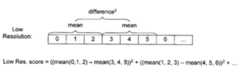
- a low-resolution Brenner scoreis calculated by squaring the difference of the means of neighboring triples of pixels and summing the squared differences over a set of pixels within the digital image.
- ratiomay be used to refer to dividing a high-resolution texture score by a low-resolution texture score or, alternatively, dividing a low-resolution texture score by a high-resolution texture score.
- a focus score indicative of the focus qualityis then established based on the calculated ratio.
- the focus scoremay include, for instance, an estimated displacement from the ideal focal height.
- a method of focusing a specimen imaging apparatusincludes the steps of obtaining a digital image of a specimen using the specimen imaging apparatus, the digital image comprising a plurality of pixels.
- a high-resolution Brenner scoreis calculated by squaring the difference of the means of neighboring pairs of pixels and summing the squared differences over a set of pixels within the digital image.
- a low-resolution Brenner scoreis calculated by squaring the difference of the means of neighboring triples of pixels and summing the squared differences over a set of pixels within the digital image.
- the ratio of the high-resolution Brenner score to the low-resolution Brenner scoreis calculated.
- the focal length of the specimen imaging apparatusis then adjusted based on the ratio.
- the focusing methodmay include the additional step of acquiring one or more digital images of the specimen and re-calculating the Brenner score or Brenner ratio to assess the improvement in focus. Additional digital images may be obtained and analyzed until the focal plane is at or near the optimal or true focus height. Because the Brenner score as a function of focal height is a bell-shaped curve (an exponentiated quadratic function), the location of its peak can be estimated from three or more points using inverse parabolic interpolation on the logarithms of the focus scores.
- a method of performing a quality check on a digital image of a specimen contained on a specimen holderincludes the steps of obtaining a digital image of a specimen, the digital image comprising a plurality of pixels.
- a high-resolution Brenner scoreis calculated by squaring the difference of the means of neighboring pairs of pixels and summing the squared differences over a set of pixels within the digital image.
- a low-resolution Brenner scoreis calculated by squaring the difference of the means of neighboring triples of pixels and summing the squared differences over a set of pixels within the digital image.
- the ratio of the low-resolution Brenner score to the high-resolution Brenner scoreis calculated.
- the digital imageis either accepted or rejected based on the calculated ratio.
- An automated imaging systemmay either immediately adjust the focus and acquire new images when focus quality is determined to be unsatisfactory, or may continue imaging but reprocess an entire sample if the number of poorly focused images crosses a given threshold.
- a method of focusing on a specimen using an automatic imaging apparatusincludes the steps of obtaining three digital images of the specimen at different focal heights using the imaging apparatus.
- the digital imageis formed from a plurality of pixels.
- a Brenner auto-focus scoreis calculated for each of the three digital images.
- An exponentiated quadratic functionis fit to the (x, y) points formed by the three focal heights and the corresponding Brenner scores.
- a new imageis acquired at a new focal height based on the function fitted to the data.
- a new Brenner scoreis calculated for the new image. Additional images are acquired the different new (e.g., modified) focal heights until the ideal focal height is reached.
- the processmay stop when the imaging apparatus senses that it is within close proximity to the ideal focal height (e.g., +/ ⁇ a displacement value).
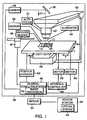
- FIG. 1schematically illustrates an exemplary specimen imaging apparatus.
- FIG. 2Ais a graphical representation of the calculation of the Brenner score for a small scale texture (e.g., blocks of two pixels).
- FIG. 2Bis a graphical representation of the calculation of the Brenner score for a larger scale texture (e.g., three blocks of pixels).
- FIG. 3is a scatter plot of the ratio of small scale (high-resolution) Brenner score to larger scale (low-resolution) Brenner score as a function of displacement from the ideal focal height.
- the scatter plot datawas obtained from 12,000 images taken across a test set of thirty slides.
- FIG. 4is a graph illustrating the root mean squared error of the predicted displacement compared to actual displacement for the 12,000 images of FIG. 3 .
- FIG. 5is a graph illustrating Brenner scores obtained at offsets of 0, ⁇ 4, and ⁇ 8 microns from initial height (solid data points).
- the dotted lineis a best fit calculated using only the three data points.
- the hollow data pointsrepresent additional Brenner scores obtained at one micron incremental movements.
- FIG. 1illustrates an exemplary specimen imaging apparatus 32 of the present invention.
- the image processing apparatus 32includes a first optical system 38 , and a slide stage 40 movable relative thereto.
- a review station 36is provided and includes a second optical system 44 , and is connected to the image processing system 32 via the server 34 .
- An internal computer system 46controls the first optical system 38 and is in communication with the server 34 .
- the first optical system 38includes an electronic camera 48 , such as a CCD camera 48 , and a microscope 50 .
- the microscope 50is preferably an automated microscope.
- the automated microscope 50may include features to provide fast, precise imaging of an area of a slide 10 positioned in the optical path 51 of the microscope 50 , such as an autofocusing mechanism 54 .
- the first optical system 38may include one or more lens systems 52 .
- An illuminator 42may provide illumination for the specimen 14 deposited on the slide 10 and generally may illuminate the slide 10 from below the stage 40 .
- the stage 40transports the specimen slide 10 into and within the optical path 51 of the microscope 50 , in response to appropriate commands from the internal computer system 46 .
- a robotic slide handler 64may, upon appropriate commands from the computer system 46 , move the specimen slide 10 from a slide-holding cassette to the movable stage 40 for imaging the cells in the specimen, and then back to the cassette after imaging.
- a slide holder 65fixedly and removably positions a slide 10 repeatedly in a precise location and orientation on the stage 40 .
- the stage 40may be motorized, and powered by one or more stage motors 56 .
- the stage 40may be mounted upon bearings 58 , which in turn are mounted to the base 59 of the microscope 50 .
- the stage 40is movable in an x-y plane.
- an interface controller 60 in communication with the movable stage 40may provide precise controlled movements of the slide 10 relative to the optical path 51 and viewing area of the microscope 50 .
- the interface controller 60controls the stage motors 56 by converting commands from the computer system 46 into appropriate signals that cause the motors 56 to move the stage 40 to prescribed locations.
- a position encoder 62may detect the precise location of the stage 40 , producing to the computer system 46 pulses representative of the movement or location of the stage. As known in the art, these pulses may be decoded by the computer system 46 in order to identify the location of the stage 40 in an imaging station coordinate system.
- the image processing system 32may include an optional bar code reader 66 positioned to view the area of a slide containing a bar code, once the slide 10 has been transported to the movable stage 40 by the robotic slide handler 64 or has been loaded manually.
- the image processing system 32may include a marker 68 that automatically places a dot, a mark, or other visible sign in the areas of interest within the specimen where potentially abnormal cells may be located.
- the review station 36is connected to the image processing system 32 via the server 34 , and may be remotely located.
- the review station 36includes a second optical system 44 .
- the second optical system 44may include any and all features of the first optical system 38 .
- the second optical system 44includes a microscope 50 that is connected to a movable stage and that is adapted for use by a human operator for visual inspection of the areas of interest identified by the image processing system 32 .
- the image processing system 32performs an initial viewing and screening of a slide 10 on which a cytological specimen 14 is disposed, in order to make a preliminary assessment of the specimen 14 .
- the image processing system 32identifies for subsequent viewing by a cytotechnologist or pathologist the locations of those areas of interest on the slide that potentially are most relevant.
- the locations of areas that are identified by the image processing system 32 in this preliminary screeningmust be accurate to within an acceptable error margin. Incorrect handling or positioning of the slides during the scanning process may cause errors in the locations of the identified areas and subsequent misreading at the review station 36 .
- a methodfor determining the focus quality of a digital image obtained using the image processing system 32 .
- the methodinvolves first obtaining a digital image of a specimen 14 .
- the digital imagemay be acquired using a camera 48 .
- the digital image of the specimen 14is formed by an array of pixels 100 .
- FIGS. 2A and 2Billustrate a portion of adjacent pixels 100 within the digital image.
- Each pixel 100 within the imagemay be represented by an 8-bit (e.g., byte) number that represents the intensity or brightness for that particular pixel.
- Each pixel's valuemay be linearly proportional to the number of photons that struck the corresponding bin of the camera 48 when the shutter was opened.
- each pixel 100may be assigned one of 256 potential values representing the pixel's brightness or intensity.
- the imaging systemanalyzes 8-bit grayscale images.
- high-resolution texture of the digital imageis obtained by calculating a high-resolution Brenner score (BR HR ).
- the high-resolution Brenner scoreis calculated by squaring the difference of the means of neighboring pairs of pixels and summing the squared differences over a set of pixels 100 within the digital image.
- the high-resolution Brenner scoremay be calculated using Equation 1, where rows and cols are the number of rows and columns of pixels in the image and P i,j is the value of the pixel in row I and column j. This equation is set forth visually illustrated in FIG. 2A .
- a low-resolution texture of the imageis obtained by calculating a low-resolution Brenner score (BR LR ).
- the low-resolution Brenner scoreis calculated by squaring the difference of the means of neighboring triples of pixels and summing the squared differences over a set of pixels within the digital image.
- the low-resolution Brenner scoremay be calculated using Equation 2 set forth below and also visually illustrated in FIG. 2B :
- the low-solution Brenner scoreis obtained by increasing the width of the averaging window from two pixels to three pixels.
- the wider averaging windoweffectively reduces the resolution of the image.
- the quality of focus of a digital imageis estimated by comparing the high-resolution Brenner score and the low-resolution Brenner score.
- the high-resolution scorecan be divided by the low-resolution score (BR HR /BR LR ).
- the low-resolution scorecan be divided by the high-resolution score (BR LR /BR HR ).
- the score calculation and comparisonmay be done by the internal computer system 46 or by some other computer device operatively connected to the specimen imaging apparatus 32 .
- a focus scoreis then established.
- the focus scoreis obtained using experimentally derived data that relates the degree of displacement from optimal or true focus as a function of the ratio of the high-resolution Brenner score to the low-resolution Brenner score.
- the best fit functionis calculated for this data.
- the inverse of this functioncan then be used to map measured ratios to estimated displacements.
- a ratio of 0.45may correspond to a focus score that indicates that the focus of the imaging apparatus 32 is +/ ⁇ 12.5 ⁇ m from true focus.
- the focus scoremay be an actual displacement value (i.e., distance). Alternatively, the focus score may be a percentage value.
- FIG. 3is a scatter plot of the ratio for each of the 12,000 images plotted as a function of the displacement from the ideal focus.
- the y-axis of the graph in FIG. 3represents (BR HR /BR LR ) while the x-axis of the graph illustrates the degree of displacement from optical focus (expressed both as positive and negative displacement).
- the datanaturally form a bell-shaped curve with the peak of the curve corresponding to the optimal focal height.
- the Brenner ratio(high-resolution/low-resolution and low-resolution/high-resolution) thus provides a relatively constant metric to measure the quality of focus for images taken from different slides.
- Equation 3gives the equation for a bell curve centered on the y axis, where parameters a and c control the width and height of the peak and d is the displacement from the ideal focal height: ratio ⁇ e a ⁇ d 2 +c (Eq. 3)
- the parameterscan be determined by minimizing the sum of squared errors between the actual ratio and the ratio predicted from the displacement using Equation 3. Let y be equal to the natural logarithm of the measured ratio (BR HR /BR LR ), and let ⁇ be the natural logarithm of the predicted ratio:
- a value for y and ⁇can be calculated.
- y i and ⁇ ibe the corresponding values
- d ibe the displacement of that image.
- the ideal values of parameters a and care those which minimize the sum of squared errors across all images in the sample set:
- Values for a and ccan be determined by setting the partial derivatives with respect to a and c to zero:
- FIG. 4illustrates the root mean squared (RMS) error of the predicted displacement using Eq. 9 as compared to the actual displacement values for the 12,000 images.
- RMS valuesare shown on the y-axis while displacement is illustrated on the x-axis.
- FIG. 4at displacements of less than 5 ⁇ m there is little visual effect and deviations are hard to discern. However, between about 5 ⁇ m and 12 ⁇ m the error is near or below 1 ⁇ m. Deviations become larger above 12 ⁇ m. This can also be seen from FIG. 3 which shows significant scatter of the data points above this limit.
- the displacement from ideal focuscan then be determined.
- the displacement from the ideal focal heightmay be estimated from a certain ratio based on a model formula like Equation 3 above. It should be noted that a given ratio provides two possible displacement values—one positive and one negative.
- the focus score or reading obtained in the above mannermay be used in a number of ways.
- the methodmay be used to determine whether a single digital image is accepted or rejected. For example, if the displacement falls outside a pre-determined threshold value, then the image may be rejected. This may mean that a new image must be acquired from the same location, at a different focal height.
- the focus scoremay be obtained for images from a plurality of specimens loaded into the specimen imaging apparatus 32 . For example, the average of the focus scores of all the images from a given slide may be measured, or their standard deviation. Alternatively the number of images for a given slide that scored above a certain threshold could be measured. Particular slides within a batch may then be reprocessed if their focus scores are found to be unacceptable.
- a rolling or cumulative scoremay be given to multiple slides within a batch. If the rolling or cumulative score crosses a pre-determined threshold then those slides may be deemed suspect and, consequently, may need to be rescanned.
- the thresholdmay be a preset displacement value, a standard deviation value, a percentage, or other metric.
- an automated imaging devicemay track the number of images from a given slide that fall outside a given range of acceptable scores. If the number of images failing these criteria is above a certain number, the slide may be reprocessed. For instance, an imaging device might reprocess any slide for which more than 100 of the 2000 images acquired from the slide fall outside the acceptable range. Alternatively, individual slides or batches of slides may be flagged if their respective focus scores go beyond a pre-determined threshold value or range. The user can then accept the slides or opt to run them again through the specimen imaging apparatus 32 . In another aspect of the invention, the specimen imaging apparatus may attempt to recalibrate itself or inform the user that maintenance is required if more than a certain percentage of slides are rejected in this manner.
- an automated imaging devicemay calculate the Brenner ratio score for each image acquired and acquire a new image at the same location whenever the score is unacceptable. The device may move back to that location immediately when it discovers the error, or it may remember all locations where the image was unacceptable and return to those locations to acquire new images after the rest of the slide has been scanned.
- an automated imaging devicemay recognize a trend in the ratio scores and attempt to correct future focus movements based on that trend. For example, if all images are estimated to have a displacement of 4 ⁇ m, the device may acquire the next image at a height of 1 ⁇ m above where it otherwise would have. If the estimated displacement of the next image is reduced, the device may continue increasing the height offset in increments of 1 ⁇ m until doing so no longer increases the focus quality. If instead the estimated displacement of the next image is greater, the device may increment the offset in the opposite direction.
- this processis made more efficient and accurate by fitting a curve to the autofocus scores and adjusting the focal height based on that curve.
- Multiple digital imagesare acquired with each digital image being acquired at a different focal height.
- a Brenner scoreis then calculated for each image and a function (e.g., curve) is generated that fits the scores and allows the peak of the Brenner function (the optimal or ideal focal height) to be estimated.
- the focal lengthcan then be adjusted using the generated curve for the data.
- a digital image of the specimen 14is acquired.
- a high-resolution Brenner scoreis calculated by squaring the difference of the means of neighboring pairs of pixels and summing the squared differences over a set of pixels 100 within the digital image.
- a low-resolution Brenner scoreis calculated by squaring the difference of the means of neighboring triples of pixels and summing the squared differences over a set of pixels within the digital image.
- a ratiois then calculated by dividing the high-resolution Brenner score by the low-resolution Brenner score.
- the ratiois calculated by dividing the low-resolution Brenner score by the high-resolution Brenner score.
- the focal lengthis then adjusted. The degree of adjustment is determined by experimental data or through a modeling equation like Equation 3 that relates the ratio to the degree of displacement from optimal focus.
- the specimen imaging apparatus 32may randomly pick one of the two options and move accordingly. A second (or additional) image may then be obtained to check whether the optimal focus has been reached.
- the systemmay be set such that the initial image is predicted to be on one, known side of the focal plane. For example, the initial image may be taken at a position such that it is reasonable to estimate that the sample needs to move closer to the optics. In this regard, the system can make a second adjustment or additional adjustments to decrease the focal length to reach the optical focal position.
- the computer system 46 of the specimen imaging apparatus 32may include a look-up table or database that includes displacement values as a function of the calculated ratio. In this regard, a quick determination can be made regarding the estimated displacement from true focus. Once the estimated displacement value is obtained from the database or look-up table, the specimen 14 (via the moveable stage 40 ) can be moved toward or further away from the device optics. Alternatively, the coefficients for an equation such as Equation 9 can be calculated based on a data set and the inverse of the equation may be used to predict displacement as a function of the calculated ratio.
- the specimen 14(and/or optics) is moved to adjust to the predicted correct focal plane
- another image of the specimenmay be obtained via the specimen imaging apparatus 32 .
- the second imagemay be used to confirm whether or not the new position is at or close enough to the optical focal position. This can be determined by again calculating the Brenner score or ratio as described herein. For example, if the second, new position is still some distance away from the optimal focal position, the specimen 14 and/or optics may be moved a certain amount (i.e., displacement) as directed by the new score or ratio. This process may be repeated any number of times until the device 32 has reached the optimal (or near-optimal) focal plane.
- a device which uses the standard autofocusing method of acquiring multiple images at different focal heightscan be modified to fit a bell curve equation to the scores from these multiple images and to interpolate the peak of the bell curve from the data.
- data pointscan be gathered at relatively larger offsets (e.g., 4 ⁇ m) but the ideal focal height can be estimated with a much finer resolution.
- FIG. 5illustrates a graph of the Brenner score (y-axis) as a function of displacement.
- the three solid diamondsrepresent data points gathered using stepping increments of 4 ⁇ m.
- the dashed linerepresents a best fit using the three (solid diamond) data points.
- the best fitis a bell-shaped curve that can be modeled or approximated using an exponential function like that of Equation 3. Given a fit to the focus scores for the same field at multiple heights, the peak (or optical focal position) of the focus score curve can be found. This gives an estimate with finer resolution than the step height between individual frames.
- FIG. 5also illustrates, with hollow diamonds, actual data obtained by stepping focal plane in small, 1 ⁇ m. As seen in FIG. 5 , the best fit curve shows near-perfect alignment with the data obtained from the 1 ⁇ m stepwise adjustment of the focal plane. This shows that estimating the peak from the widely spaced filled points will result in as much of an accuracy improvement as would be gained by acquiring more images at smaller intervals, but without the additional time that would be needed to acquire these images.
- the speed and accuracy of focusing operations in specimen imaging devicescan be increased.
- the focusing algorithmcan fit a curve to the existing set of points and then acquire the next image at the estimated peak of the curve, allowing it to more quickly converge on the peak.
- the embodimentsdescribe the use of the Brenner score to calculate and measure small-scale and larger-scale texture in digital images. It should be understood, however, that other autofocus scoring methods known to those skilled in the art may also be employed to quantify small-scale and larger-scale texture resolutions.
Landscapes
- Engineering & Computer Science (AREA)
- Physics & Mathematics (AREA)
- General Physics & Mathematics (AREA)
- Computer Vision & Pattern Recognition (AREA)
- Chemical & Material Sciences (AREA)
- Theoretical Computer Science (AREA)
- Quality & Reliability (AREA)
- Analytical Chemistry (AREA)
- Optics & Photonics (AREA)
- Microscoopes, Condenser (AREA)
- Automatic Focus Adjustment (AREA)
- Studio Devices (AREA)
- Length Measuring Devices By Optical Means (AREA)
Abstract
Description
ratio≈ea·d
Claims (17)
Priority Applications (14)
| Application Number | Priority Date | Filing Date | Title |
|---|---|---|---|
| US11/609,274US7769219B2 (en) | 2006-12-11 | 2006-12-11 | Method for assessing image focus quality |
| AU2007333324AAU2007333324B2 (en) | 2006-12-11 | 2007-11-27 | Method for assessing image focus quality |
| PCT/US2007/085627WO2008073700A2 (en) | 2006-12-11 | 2007-11-27 | Method for assessing image focus quality |
| CA2669922ACA2669922C (en) | 2006-12-11 | 2007-11-27 | Method for assessing image focus quality |
| EP07864831.8AEP2102816B1 (en) | 2006-12-11 | 2007-11-27 | Method for assessing image focus quality |
| CN2011101201095ACN102176245B (en) | 2006-12-11 | 2007-11-27 | Method for focusing automatic imaging device on specimen |
| JP2009540386AJP5161889B2 (en) | 2006-12-11 | 2007-11-27 | Method for assessing image focus quality |
| CA2827703ACA2827703C (en) | 2006-12-11 | 2007-11-27 | Method for assessing image focus quality |
| CN200780045741XACN101558430B (en) | 2006-12-11 | 2007-11-27 | Methods for Evaluating Image Focus Quality |
| HK09110287.2AHK1130345B (en) | 2006-12-11 | 2007-11-27 | Method for assessing image focus quality |
| TW100133691ATWI478101B (en) | 2006-12-11 | 2007-12-10 | Method for assessing image focus quality |
| TW096147108ATWI370412B (en) | 2006-12-11 | 2007-12-10 | Method for assessing image focus quality |
| US12/767,316US8014583B2 (en) | 2006-12-11 | 2010-04-26 | Method for assessing image focus quality |
| JP2011226454AJP5489177B2 (en) | 2006-12-11 | 2011-10-14 | Method for focusing image processing apparatus |
Applications Claiming Priority (1)
| Application Number | Priority Date | Filing Date | Title |
|---|---|---|---|
| US11/609,274US7769219B2 (en) | 2006-12-11 | 2006-12-11 | Method for assessing image focus quality |
Related Child Applications (1)
| Application Number | Title | Priority Date | Filing Date |
|---|---|---|---|
| US12/767,316DivisionUS8014583B2 (en) | 2006-12-11 | 2010-04-26 | Method for assessing image focus quality |
Publications (2)
| Publication Number | Publication Date |
|---|---|
| US20080137938A1 US20080137938A1 (en) | 2008-06-12 |
| US7769219B2true US7769219B2 (en) | 2010-08-03 |
Family
ID=39326970
Family Applications (2)
| Application Number | Title | Priority Date | Filing Date |
|---|---|---|---|
| US11/609,274Active2029-05-30US7769219B2 (en) | 2006-12-11 | 2006-12-11 | Method for assessing image focus quality |
| US12/767,316ActiveUS8014583B2 (en) | 2006-12-11 | 2010-04-26 | Method for assessing image focus quality |
Family Applications After (1)
| Application Number | Title | Priority Date | Filing Date |
|---|---|---|---|
| US12/767,316ActiveUS8014583B2 (en) | 2006-12-11 | 2010-04-26 | Method for assessing image focus quality |
Country Status (8)
| Country | Link |
|---|---|
| US (2) | US7769219B2 (en) |
| EP (1) | EP2102816B1 (en) |
| JP (2) | JP5161889B2 (en) |
| CN (2) | CN101558430B (en) |
| AU (1) | AU2007333324B2 (en) |
| CA (2) | CA2669922C (en) |
| TW (2) | TWI370412B (en) |
| WO (1) | WO2008073700A2 (en) |
Cited By (22)
| Publication number | Priority date | Publication date | Assignee | Title |
|---|---|---|---|---|
| US9041791B2 (en) | 2011-02-01 | 2015-05-26 | Roche Diagnostics Hematology, Inc. | Fast auto-focus in imaging |
| US20160051215A1 (en)* | 2013-03-15 | 2016-02-25 | Hologic, Inc. | System and method for navigating a tomosynthesis stack including automatic focusing |
| US9754237B2 (en)* | 2015-12-18 | 2017-09-05 | Ricoh Co., Ltd. | Index image quality metric |
| WO2020091965A2 (en) | 2018-11-02 | 2020-05-07 | Hologic, Inc. | Digital imaging system and method |
| US11403483B2 (en) | 2017-06-20 | 2022-08-02 | Hologic, Inc. | Dynamic self-learning medical image method and system |
| US11406332B2 (en) | 2011-03-08 | 2022-08-09 | Hologic, Inc. | System and method for dual energy and/or contrast enhanced breast imaging for screening, diagnosis and biopsy |
| US11419565B2 (en) | 2014-02-28 | 2022-08-23 | IIologic, Inc. | System and method for generating and displaying tomosynthesis image slabs |
| US11445993B2 (en) | 2017-03-30 | 2022-09-20 | Hologic, Inc. | System and method for targeted object enhancement to generate synthetic breast tissue images |
| US11452486B2 (en) | 2006-02-15 | 2022-09-27 | Hologic, Inc. | Breast biopsy and needle localization using tomosynthesis systems |
| US11455719B2 (en) | 2016-06-15 | 2022-09-27 | Q-Linea Ab | Image based analysis of samples |
| US11455754B2 (en) | 2017-03-30 | 2022-09-27 | Hologic, Inc. | System and method for synthesizing low-dimensional image data from high-dimensional image data using an object grid enhancement |
| US11467390B2 (en) | 2013-07-18 | 2022-10-11 | Ventana Medical Systems, Inc. | Auto-focus methods and systems for multi-spectral imaging |
| US11508340B2 (en) | 2011-11-27 | 2022-11-22 | Hologic, Inc. | System and method for generating a 2D image using mammography and/or tomosynthesis image data |
| US11589944B2 (en) | 2013-03-15 | 2023-02-28 | Hologic, Inc. | Tomosynthesis-guided biopsy apparatus and method |
| US11663780B2 (en) | 2012-02-13 | 2023-05-30 | Hologic Inc. | System and method for navigating a tomosynthesis stack using synthesized image data |
| US11701199B2 (en) | 2009-10-08 | 2023-07-18 | Hologic, Inc. | Needle breast biopsy system and method of use |
| US11775156B2 (en) | 2010-11-26 | 2023-10-03 | Hologic, Inc. | User interface for medical image review workstation |
| US11957497B2 (en) | 2017-03-30 | 2024-04-16 | Hologic, Inc | System and method for hierarchical multi-level feature image synthesis and representation |
| US12029602B2 (en) | 2013-10-24 | 2024-07-09 | Hologic, Inc. | System and method for navigating x-ray guided breast biopsy |
| US12236582B2 (en) | 2018-09-24 | 2025-02-25 | Hologic, Inc. | Breast mapping and abnormality localization |
| US12236597B2 (en) | 2021-11-29 | 2025-02-25 | Hologic, Inc. | Systems and methods for correlating objects of interest |
| US12254586B2 (en) | 2021-10-25 | 2025-03-18 | Hologic, Inc. | Auto-focus tool for multimodality image review |
Families Citing this family (75)
| Publication number | Priority date | Publication date | Assignee | Title |
|---|---|---|---|---|
| US8909325B2 (en) | 2000-08-21 | 2014-12-09 | Biosensors International Group, Ltd. | Radioactive emission detector equipped with a position tracking system and utilization thereof with medical systems and in medical procedures |
| US8565860B2 (en) | 2000-08-21 | 2013-10-22 | Biosensors International Group, Ltd. | Radioactive emission detector equipped with a position tracking system |
| US8489176B1 (en) | 2000-08-21 | 2013-07-16 | Spectrum Dynamics Llc | Radioactive emission detector equipped with a position tracking system and utilization thereof with medical systems and in medical procedures |
| EP1648286B1 (en) | 2003-07-12 | 2017-12-20 | Accelerate Diagnostics, Inc. | Sensitive and rapid biodetection |
| US20120077206A1 (en) | 2003-07-12 | 2012-03-29 | Accelr8 Technology Corporation | Rapid Microbial Detection and Antimicrobial Susceptibility Testing |
| WO2008010227A2 (en) | 2006-07-19 | 2008-01-24 | Spectrum Dynamics Llc | Imaging protocols |
| US7968851B2 (en) | 2004-01-13 | 2011-06-28 | Spectrum Dynamics Llc | Dynamic spect camera |
| WO2006051531A2 (en) | 2004-11-09 | 2006-05-18 | Spectrum Dynamics Llc | Radioimaging |
| US9470801B2 (en) | 2004-01-13 | 2016-10-18 | Spectrum Dynamics Llc | Gating with anatomically varying durations |
| US8571881B2 (en)* | 2004-11-09 | 2013-10-29 | Spectrum Dynamics, Llc | Radiopharmaceutical dispensing, administration, and imaging |
| CN1981210A (en) | 2004-01-13 | 2007-06-13 | 光谱动力学有限责任公司 | Multi-dimensional image reconstruction |
| US8586932B2 (en) | 2004-11-09 | 2013-11-19 | Spectrum Dynamics Llc | System and method for radioactive emission measurement |
| EP1778957A4 (en) | 2004-06-01 | 2015-12-23 | Biosensors Int Group Ltd | OPTIMIZING THE MEASUREMENT OF RADIOACTIVE EMISSIONS IN SPECIFIC BODY STRUCTURES |
| US9316743B2 (en) | 2004-11-09 | 2016-04-19 | Biosensors International Group, Ltd. | System and method for radioactive emission measurement |
| US9943274B2 (en) | 2004-11-09 | 2018-04-17 | Spectrum Dynamics Medical Limited | Radioimaging using low dose isotope |
| US8615405B2 (en) | 2004-11-09 | 2013-12-24 | Biosensors International Group, Ltd. | Imaging system customization using data from radiopharmaceutical-associated data carrier |
| WO2008059489A2 (en) | 2006-11-13 | 2008-05-22 | Spectrum Dynamics Llc | Radioimaging applications of and novel formulations of teboroxime |
| US8644910B2 (en) | 2005-07-19 | 2014-02-04 | Biosensors International Group, Ltd. | Imaging protocols |
| US8837793B2 (en) | 2005-07-19 | 2014-09-16 | Biosensors International Group, Ltd. | Reconstruction stabilizer and active vision |
| US8894974B2 (en) | 2006-05-11 | 2014-11-25 | Spectrum Dynamics Llc | Radiopharmaceuticals for diagnosis and therapy |
| WO2008075362A2 (en)* | 2006-12-20 | 2008-06-26 | Spectrum Dynamics Llc | A method, a system, and an apparatus for using and processing multidimensional data |
| US8023714B2 (en)* | 2007-06-06 | 2011-09-20 | Aperio Technologies, Inc. | System and method for assessing image interpretability in anatomic pathology |
| US8521253B2 (en) | 2007-10-29 | 2013-08-27 | Spectrum Dynamics Llc | Prostate imaging |
| KR101011779B1 (en)* | 2008-12-19 | 2011-02-07 | 에이피시스템 주식회사 | Vision System for Substrate Alignment and its Focusing Method |
| US8338788B2 (en) | 2009-07-29 | 2012-12-25 | Spectrum Dynamics Llc | Method and system of optimized volumetric imaging |
| US8570370B2 (en) | 2009-08-31 | 2013-10-29 | Bio-Rad Laboratories, Inc. | Compact automated cell counter |
| EP2519853A2 (en)* | 2009-12-31 | 2012-11-07 | Abbott Point Of Care, Inc. | Method and apparatus for fast focus imaging biologic specimens |
| US8396269B2 (en) | 2010-04-08 | 2013-03-12 | Digital Pathco LLC | Image quality assessment including comparison of overlapped margins |
| EP2616925A4 (en) | 2010-09-16 | 2014-02-12 | Omnyx LLC | Histology workflow management system |
| US20120127297A1 (en)* | 2010-11-24 | 2012-05-24 | Baxi Vipul A | Digital microscopy with focus grading in zones distinguished for comparable image structures |
| JP5727629B2 (en)* | 2011-02-01 | 2015-06-03 | コンスティテューション・メディカル・インコーポレイテッドConstitution Medical, Inc. | High-speed automatic focusing in microscope imaging |
| US10254204B2 (en) | 2011-03-07 | 2019-04-09 | Accelerate Diagnostics, Inc. | Membrane-assisted purification |
| EP2683831B1 (en) | 2011-03-07 | 2015-09-23 | Accelerate Diagnostics, Inc. | Rapid cell purification systems |
| EP2518690A1 (en)* | 2011-04-28 | 2012-10-31 | Koninklijke Philips Electronics N.V. | Medical image processing system and method |
| EP2732432B1 (en)* | 2011-07-13 | 2020-01-08 | Koninklijke Philips N.V. | Method for automatically adjusting a focal plane of a digital pathology image |
| EP2845045B1 (en) | 2012-05-02 | 2023-07-12 | Leica Biosystems Imaging, Inc. | Real-time focusing in line scan imaging |
| US20140186859A1 (en) | 2012-05-09 | 2014-07-03 | Advanced Animal Diagnostic, Inc. | Autofocus method for imaging a biological sample and cartridge for use therein |
| EP2863733B1 (en) | 2012-06-20 | 2019-05-08 | Advanced Animal Diagnostics, Inc. | Sample collection and transfer assembly and related methods |
| EP2802149B1 (en) | 2012-06-28 | 2020-03-18 | Nec Corporation | Camera position/posture evaluation device, camera position/posture evaluation method, and camera position/posture evaluation program |
| US9816982B2 (en) | 2012-07-03 | 2017-11-14 | Advanced Animal Diagnostics, Inc. | Diagnostic apparatus |
| US10359614B2 (en) | 2012-07-03 | 2019-07-23 | Advanced Animal Diagnostics, Inc. | Diagnostic apparatus |
| CN104956207B (en)* | 2013-03-13 | 2018-01-19 | 奥林巴斯株式会社 | Evaluation methods and phantom samples for optical analysis devices |
| CN105026977B (en)* | 2013-03-13 | 2017-09-08 | 索尼公司 | Information processing device, information processing method, and information processing program |
| US9677109B2 (en) | 2013-03-15 | 2017-06-13 | Accelerate Diagnostics, Inc. | Rapid determination of microbial growth and antimicrobial susceptibility |
| US9237847B2 (en) | 2014-02-11 | 2016-01-19 | Welch Allyn, Inc. | Ophthalmoscope device |
| US9211064B2 (en) | 2014-02-11 | 2015-12-15 | Welch Allyn, Inc. | Fundus imaging system |
| US10290019B2 (en) | 2014-10-24 | 2019-05-14 | Dropbox, Inc. | User re-engagement with online photo management service |
| US10799115B2 (en)* | 2015-02-27 | 2020-10-13 | Welch Allyn, Inc. | Through focus retinal image capturing |
| US11045088B2 (en) | 2015-02-27 | 2021-06-29 | Welch Allyn, Inc. | Through focus retinal image capturing |
| US10253355B2 (en) | 2015-03-30 | 2019-04-09 | Accelerate Diagnostics, Inc. | Instrument and system for rapid microorganism identification and antimicrobial agent susceptibility testing |
| US10023895B2 (en) | 2015-03-30 | 2018-07-17 | Accelerate Diagnostics, Inc. | Instrument and system for rapid microogranism identification and antimicrobial agent susceptibility testing |
| JP6562547B2 (en)* | 2015-07-16 | 2019-08-21 | オリンパス株式会社 | Microscope system, calculation method, and program |
| CN106371231B (en)* | 2015-07-23 | 2019-11-26 | 旭东机械工业股份有限公司 | Micro- imaging equipment |
| US10136804B2 (en) | 2015-07-24 | 2018-11-27 | Welch Allyn, Inc. | Automatic fundus image capture system |
| KR20180058730A (en)* | 2015-09-24 | 2018-06-01 | 라이카 바이오시스템즈 이미징 인크. | Real-time focusing in line scan video |
| US10772495B2 (en) | 2015-11-02 | 2020-09-15 | Welch Allyn, Inc. | Retinal image capturing |
| WO2017120217A1 (en) | 2016-01-07 | 2017-07-13 | Welch Allyn, Inc. | Infrared fundus imaging system |
| US10602926B2 (en) | 2016-09-29 | 2020-03-31 | Welch Allyn, Inc. | Through focus retinal image capturing |
| EP3351992B1 (en)* | 2017-01-24 | 2019-10-23 | Horiba France SAS | Micro-spectrometry measurement method and system |
| AU2018304105B2 (en)* | 2017-07-17 | 2020-11-19 | Welch Allyn, Inc. | Through focus retinal image capturing |
| US11067526B2 (en) | 2017-08-17 | 2021-07-20 | Abbott Point Of Care Inc. | Devices, systems, and methods for performing optical and electrochemical assays |
| CN108521544B (en)* | 2018-03-15 | 2020-09-04 | 深圳市瀚晖威视科技有限公司 | Focusing method and device for video monitoring |
| US11096574B2 (en) | 2018-05-24 | 2021-08-24 | Welch Allyn, Inc. | Retinal image capturing |
| US10713769B2 (en)* | 2018-06-05 | 2020-07-14 | Kla-Tencor Corp. | Active learning for defect classifier training |
| JP7628945B2 (en)* | 2018-07-02 | 2025-02-12 | オルト-クリニカル ダイアグノスティックス インコーポレイテッド | Method and apparatus for selecting a position for reading an image on a slide medium - Patents.com |
| US11857151B2 (en)* | 2018-09-12 | 2024-01-02 | Steris Instrument Management Services, Inc. | Systems and methods for standalone endoscopic objective image analysis |
| US11727586B2 (en)* | 2020-04-21 | 2023-08-15 | Sartorius Bioanalytical Instruments, Inc. | Image processing and segmentation of sets of Z-stacked images of three-dimensional biological samples |
| EP4206783A4 (en)* | 2020-08-31 | 2023-11-01 | Shenzhen Mindray Bio-Medical Electronics Co., Ltd. | METHOD AND DEVICE FOR PHOTOGRAPHING SAMPLE IMAGES |
| CN112288699B (en)* | 2020-10-23 | 2024-02-09 | 北京百度网讯科技有限公司 | Method, device, equipment and medium for evaluating relative definition of image |
| CN112363309B (en)* | 2020-11-13 | 2023-02-17 | 杭州医派智能科技有限公司 | Automatic focusing method and system for pathological image under microscope |
| CN114764180B (en)* | 2020-12-31 | 2023-10-27 | 深圳中科飞测科技股份有限公司 | Focusing method and focusing system for object to be measured, device and storage medium |
| CN113364986B (en)* | 2021-07-08 | 2022-08-09 | 杭州海康机器人技术有限公司 | Focusing method, device and storage medium |
| US20240109063A1 (en)* | 2022-09-29 | 2024-04-04 | Illumina, Inc. | Dynamic optical system calibration |
| WO2025022359A1 (en)* | 2023-07-26 | 2025-01-30 | Digipathai Solutions Pvt. Ltd. | Pap smear pre-screening technique |
| CN117970595B (en)* | 2024-03-27 | 2024-06-18 | 笑纳科技(苏州)有限公司 | Microscope automatic focusing method based on deep learning and image processing |
Citations (14)
| Publication number | Priority date | Publication date | Assignee | Title |
|---|---|---|---|---|
| US5647025A (en)* | 1994-09-20 | 1997-07-08 | Neopath, Inc. | Automatic focusing of biomedical specimens apparatus |
| US5790710A (en)* | 1991-07-12 | 1998-08-04 | Jeffrey H. Price | Autofocus system for scanning microscopy |
| US6201899B1 (en)* | 1998-10-09 | 2001-03-13 | Sarnoff Corporation | Method and apparatus for extended depth of field imaging |
| US6289113B1 (en)* | 1998-11-25 | 2001-09-11 | Iridian Technologies, Inc. | Handheld iris imaging apparatus and method |
| US6441855B1 (en)* | 2000-05-09 | 2002-08-27 | Eastman Kodak Company | Focusing device |
| US20030118245A1 (en)* | 2001-12-21 | 2003-06-26 | Leonid Yaroslavsky | Automatic focusing of an imaging system |
| US6640014B1 (en)* | 1999-01-22 | 2003-10-28 | Jeffrey H. Price | Automatic on-the-fly focusing for continuous image acquisition in high-resolution microscopy |
| US20040114823A1 (en)* | 2001-04-06 | 2004-06-17 | Smith Brian John Edward | Image focusing methods and apparatus |
| US20050047636A1 (en)* | 2003-08-29 | 2005-03-03 | David Gines | System and method for performing auto-focused tomosynthesis |
| US7006674B1 (en) | 1999-10-29 | 2006-02-28 | Cytyc Corporation | Apparatus and methods for verifying the location of areas of interest within a sample in an imaging system |
| US7067783B2 (en)* | 2002-09-30 | 2006-06-27 | Agilent Technologies, Inc. | Method for improved focus control in molecular array scanning by using a symmetrical filter to determine in-focus-distance |
| US20060257050A1 (en)* | 2005-05-12 | 2006-11-16 | Pere Obrador | Method and system for image quality calculation |
| US20070014468A1 (en)* | 2005-07-12 | 2007-01-18 | Gines David L | System and method for confidence measures for mult-resolution auto-focused tomosynthesis |
| US7369304B2 (en)* | 1999-10-29 | 2008-05-06 | Cytyc Corporation | Cytological autofocusing imaging systems and methods |
Family Cites Families (19)
| Publication number | Priority date | Publication date | Assignee | Title |
|---|---|---|---|---|
| JPH0829667A (en)* | 1994-07-18 | 1996-02-02 | Fuji Photo Optical Co Ltd | Automatic focusing method |
| US5989835A (en)* | 1997-02-27 | 1999-11-23 | Cellomics, Inc. | System for cell-based screening |
| JPH10197784A (en)* | 1997-01-10 | 1998-07-31 | Sankyo Seiki Mfg Co Ltd | Automatic focusing device |
| AU730100B2 (en)* | 1997-02-27 | 2001-02-22 | Cellomics, Inc. | A system for cell-based screening |
| US6416959B1 (en)* | 1997-02-27 | 2002-07-09 | Kenneth Giuliano | System for cell-based screening |
| JPH10319313A (en)* | 1997-05-21 | 1998-12-04 | Olympus Optical Co Ltd | Automatic focus detecting device |
| JP3416508B2 (en)* | 1998-03-11 | 2003-06-16 | 三洋電機株式会社 | Digital camera |
| JP4228430B2 (en)* | 1998-09-29 | 2009-02-25 | 沖電気工業株式会社 | Focus position determination method and apparatus |
| US6247813B1 (en)* | 1999-04-09 | 2001-06-19 | Iritech, Inc. | Iris identification system and method of identifying a person through iris recognition |
| EP1190271B1 (en)* | 1999-06-04 | 2003-09-03 | Janssen Pharmaceutica N.V. | Robust autofocus system for a microscope |
| US6429930B1 (en)* | 2000-09-06 | 2002-08-06 | Accent Optical Technologies, Inc. | Determination of center of focus by diffraction signature analysis |
| JP2003029138A (en)* | 2001-07-19 | 2003-01-29 | Olympus Optical Co Ltd | Autofocusing method and ultraviolet microscope |
| WO2003014795A1 (en)* | 2001-08-06 | 2003-02-20 | Bioview Ltd. | Image focusing in fluorescent imaging |
| TWI233523B (en)* | 2004-02-20 | 2005-06-01 | Premier Image Technology Corp | Fast focusing method of digital camera |
| CN100349542C (en)* | 2004-05-29 | 2007-11-21 | 倪蔚民 | Real time automatic non-invasion iris optical imaging device |
| EP1679546B1 (en)* | 2005-01-07 | 2014-12-24 | Canon Kabushiki Kaisha | Focus control method and focus control apparatus |
| US7417213B2 (en)* | 2005-06-22 | 2008-08-26 | Tripath Imaging, Inc. | Apparatus and method for rapid microscopic image focusing having a movable objective |
| US8179432B2 (en)* | 2007-04-30 | 2012-05-15 | General Electric Company | Predictive autofocusing |
| US8878923B2 (en)* | 2007-08-23 | 2014-11-04 | General Electric Company | System and method for enhanced predictive autofocusing |
- 2006
- 2006-12-11USUS11/609,274patent/US7769219B2/enactiveActive
- 2007
- 2007-11-27EPEP07864831.8Apatent/EP2102816B1/enactiveActive
- 2007-11-27CNCN200780045741XApatent/CN101558430B/enactiveActive
- 2007-11-27CACA2669922Apatent/CA2669922C/enactiveActive
- 2007-11-27CACA2827703Apatent/CA2827703C/enactiveActive
- 2007-11-27AUAU2007333324Apatent/AU2007333324B2/enactiveActive
- 2007-11-27CNCN2011101201095Apatent/CN102176245B/enactiveActive
- 2007-11-27JPJP2009540386Apatent/JP5161889B2/enactiveActive
- 2007-11-27WOPCT/US2007/085627patent/WO2008073700A2/enactiveApplication Filing
- 2007-12-10TWTW096147108Apatent/TWI370412B/enactive
- 2007-12-10TWTW100133691Apatent/TWI478101B/enactive
- 2010
- 2010-04-26USUS12/767,316patent/US8014583B2/enactiveActive
- 2011
- 2011-10-14JPJP2011226454Apatent/JP5489177B2/enactiveActive
Patent Citations (15)
| Publication number | Priority date | Publication date | Assignee | Title |
|---|---|---|---|---|
| US5790710A (en)* | 1991-07-12 | 1998-08-04 | Jeffrey H. Price | Autofocus system for scanning microscopy |
| US5647025A (en)* | 1994-09-20 | 1997-07-08 | Neopath, Inc. | Automatic focusing of biomedical specimens apparatus |
| US6201899B1 (en)* | 1998-10-09 | 2001-03-13 | Sarnoff Corporation | Method and apparatus for extended depth of field imaging |
| US6289113B1 (en)* | 1998-11-25 | 2001-09-11 | Iridian Technologies, Inc. | Handheld iris imaging apparatus and method |
| US6640014B1 (en)* | 1999-01-22 | 2003-10-28 | Jeffrey H. Price | Automatic on-the-fly focusing for continuous image acquisition in high-resolution microscopy |
| US7006674B1 (en) | 1999-10-29 | 2006-02-28 | Cytyc Corporation | Apparatus and methods for verifying the location of areas of interest within a sample in an imaging system |
| US7369304B2 (en)* | 1999-10-29 | 2008-05-06 | Cytyc Corporation | Cytological autofocusing imaging systems and methods |
| US7468836B2 (en)* | 1999-10-29 | 2008-12-23 | Cytyc Corporation | Cytological imaging systems and methods |
| US6441855B1 (en)* | 2000-05-09 | 2002-08-27 | Eastman Kodak Company | Focusing device |
| US20040114823A1 (en)* | 2001-04-06 | 2004-06-17 | Smith Brian John Edward | Image focusing methods and apparatus |
| US20030118245A1 (en)* | 2001-12-21 | 2003-06-26 | Leonid Yaroslavsky | Automatic focusing of an imaging system |
| US7067783B2 (en)* | 2002-09-30 | 2006-06-27 | Agilent Technologies, Inc. | Method for improved focus control in molecular array scanning by using a symmetrical filter to determine in-focus-distance |
| US20050047636A1 (en)* | 2003-08-29 | 2005-03-03 | David Gines | System and method for performing auto-focused tomosynthesis |
| US20060257050A1 (en)* | 2005-05-12 | 2006-11-16 | Pere Obrador | Method and system for image quality calculation |
| US20070014468A1 (en)* | 2005-07-12 | 2007-01-18 | Gines David L | System and method for confidence measures for mult-resolution auto-focused tomosynthesis |
Non-Patent Citations (9)
| Title |
|---|
| Brenner, John F., Brock S. Dew, J. Brian Horton, Thomas King, Peter W. Neurath and William D. Selles, "An Automated Microscope for Cytologic Research", The Journal of Histochemistry and Cytochemistry, copyright 1976, The Histochemical Society, Inc. vol. 24, No. 1, pp. 100-111 (1976) (12 pages). |
| Bueno-Ibarra et al., "Fast Autofocus Algorithm for Automated Microscopes", Optical Engineering, vol. 44 , No. 6, Jun. 30, 2005, pp. 063601-1 to 063601-8 (8 pages). |
| Geusebroek et al., "Robust Autofocusing in Microscopy", Cytometry, Alan Liss, New York, vol. 39, No. 1, Feb. 1, 2000, pp. 1-9 (9 pages). |
| Kenny L. C., "Automated Focusing of an Optical Microscope", Journal of Microscopy, Oxford, vol. 132, Pt. 1, Oct. 1, 1983, pp. 97-107 (11 pages). |
| PCT International Search Report and Written Opinion of the International Search Authority for PCT/US2007/085627, Applicant Cytyc Corporation, Forms PCT/ISA/210, 220 and 237, dated Sep. 24, 2008 (18 pages). |
| PCT Invitation to Pay Additional Fees and Partial Search Report for PCT/US2007/085627, Applicant Cytyc Corp., form PCT/ISA/206, dated Jun. 10, 2008 (9 pages). |
| Santos, A., C. Ortiz De Solorzano, J.J. Vaquero, J. M. Pena, N. Malpica and F. Del Pozo, , "Evaluation of autofocus functions in molecular cytogenetic analysis", Journal of Microscopy, vol. 188, Pt 3, Dec. 1997, pp. 264-272 (9 pages). |
| Yu Song et al., "A New Auto-Focusing Algorithm for Optical Microscope Based Automated System", Control, Automation, Robotics, and Vision, Dec. 1, 2006, ICARCV '06, pp. 1-5 (5 pages). |
| Yu Sun et al., "Autofocusing Algorithm Selection in Computer Microscopy", Intelligent Robots and Systems, Aug. 2, 2005, pp. 419-425 (7 pages). |
Cited By (41)
| Publication number | Priority date | Publication date | Assignee | Title |
|---|---|---|---|---|
| US11452486B2 (en) | 2006-02-15 | 2022-09-27 | Hologic, Inc. | Breast biopsy and needle localization using tomosynthesis systems |
| US11918389B2 (en) | 2006-02-15 | 2024-03-05 | Hologic, Inc. | Breast biopsy and needle localization using tomosynthesis systems |
| US12193853B2 (en) | 2006-02-15 | 2025-01-14 | Hologic, Inc. | Breast biopsy and needle localization using tomosynthesis systems |
| US11701199B2 (en) | 2009-10-08 | 2023-07-18 | Hologic, Inc. | Needle breast biopsy system and method of use |
| US12193886B2 (en) | 2009-10-08 | 2025-01-14 | Hologic, Inc. | Needle breast biopsy system and method of use |
| US11775156B2 (en) | 2010-11-26 | 2023-10-03 | Hologic, Inc. | User interface for medical image review workstation |
| US10462351B2 (en) | 2011-02-01 | 2019-10-29 | Roche Diagnostics Hematology, Inc. | Fast auto-focus in imaging |
| US9813608B2 (en) | 2011-02-01 | 2017-11-07 | Roche Diagnostics Hematology, Inc. | Fast auto-focus in imaging |
| US9041791B2 (en) | 2011-02-01 | 2015-05-26 | Roche Diagnostics Hematology, Inc. | Fast auto-focus in imaging |
| US12239471B2 (en) | 2011-03-08 | 2025-03-04 | Hologic, Inc. | System and method for dual energy and/or contrast enhanced breast imaging for screening, diagnosis and biopsy |
| US11406332B2 (en) | 2011-03-08 | 2022-08-09 | Hologic, Inc. | System and method for dual energy and/or contrast enhanced breast imaging for screening, diagnosis and biopsy |
| US11837197B2 (en) | 2011-11-27 | 2023-12-05 | Hologic, Inc. | System and method for generating a 2D image using mammography and/or tomosynthesis image data |
| US12183309B2 (en) | 2011-11-27 | 2024-12-31 | Hologic, Inc. | System and method for generating a 2D image using mammography and/or tomosynthesis image data |
| US11508340B2 (en) | 2011-11-27 | 2022-11-22 | Hologic, Inc. | System and method for generating a 2D image using mammography and/or tomosynthesis image data |
| US11663780B2 (en) | 2012-02-13 | 2023-05-30 | Hologic Inc. | System and method for navigating a tomosynthesis stack using synthesized image data |
| US12307604B2 (en) | 2012-02-13 | 2025-05-20 | Hologic, Inc. | System and method for navigating a tomosynthesis stack using synthesized image data |
| US12211608B2 (en) | 2013-03-15 | 2025-01-28 | Hologic, Inc. | System and method for navigating a tomosynthesis stack including automatic focusing |
| US11589944B2 (en) | 2013-03-15 | 2023-02-28 | Hologic, Inc. | Tomosynthesis-guided biopsy apparatus and method |
| US12324707B2 (en) | 2013-03-15 | 2025-06-10 | Hologic, Inc. | Tomosynthesis-guided biopsy in prone |
| US10624598B2 (en)* | 2013-03-15 | 2020-04-21 | Hologic, Inc. | System and method for navigating a tomosynthesis stack including automatic focusing |
| US12064291B2 (en) | 2013-03-15 | 2024-08-20 | Hologic, Inc. | Tomosynthesis-guided biopsy in prone |
| US20160051215A1 (en)* | 2013-03-15 | 2016-02-25 | Hologic, Inc. | System and method for navigating a tomosynthesis stack including automatic focusing |
| US11467390B2 (en) | 2013-07-18 | 2022-10-11 | Ventana Medical Systems, Inc. | Auto-focus methods and systems for multi-spectral imaging |
| US12029602B2 (en) | 2013-10-24 | 2024-07-09 | Hologic, Inc. | System and method for navigating x-ray guided breast biopsy |
| US11801025B2 (en) | 2014-02-28 | 2023-10-31 | Hologic, Inc. | System and method for generating and displaying tomosynthesis image slabs |
| US11419565B2 (en) | 2014-02-28 | 2022-08-23 | IIologic, Inc. | System and method for generating and displaying tomosynthesis image slabs |
| US9754237B2 (en)* | 2015-12-18 | 2017-09-05 | Ricoh Co., Ltd. | Index image quality metric |
| US11455719B2 (en) | 2016-06-15 | 2022-09-27 | Q-Linea Ab | Image based analysis of samples |
| US12211124B2 (en) | 2017-03-30 | 2025-01-28 | Hologic, Inc. | System and method for synthesizing low-dimensional image data from high-dimensional image data using an object grid enhancement |
| US12070349B2 (en) | 2017-03-30 | 2024-08-27 | Hologic, Inc. | System and method for targeted object enhancement to generate synthetic breast tissue images |
| US11455754B2 (en) | 2017-03-30 | 2022-09-27 | Hologic, Inc. | System and method for synthesizing low-dimensional image data from high-dimensional image data using an object grid enhancement |
| US11445993B2 (en) | 2017-03-30 | 2022-09-20 | Hologic, Inc. | System and method for targeted object enhancement to generate synthetic breast tissue images |
| US11957497B2 (en) | 2017-03-30 | 2024-04-16 | Hologic, Inc | System and method for hierarchical multi-level feature image synthesis and representation |
| US11983799B2 (en) | 2017-03-30 | 2024-05-14 | Hologic, Inc. | System and method for synthesizing low-dimensional image data from high-dimensional image data using an object grid enhancement |
| US11850021B2 (en) | 2017-06-20 | 2023-12-26 | Hologic, Inc. | Dynamic self-learning medical image method and system |
| US11403483B2 (en) | 2017-06-20 | 2022-08-02 | Hologic, Inc. | Dynamic self-learning medical image method and system |
| US12236582B2 (en) | 2018-09-24 | 2025-02-25 | Hologic, Inc. | Breast mapping and abnormality localization |
| US11977215B2 (en) | 2018-11-02 | 2024-05-07 | Hologic, Inc. | Digital imaging system and method |
| WO2020091965A2 (en) | 2018-11-02 | 2020-05-07 | Hologic, Inc. | Digital imaging system and method |
| US12254586B2 (en) | 2021-10-25 | 2025-03-18 | Hologic, Inc. | Auto-focus tool for multimodality image review |
| US12236597B2 (en) | 2021-11-29 | 2025-02-25 | Hologic, Inc. | Systems and methods for correlating objects of interest |
Also Published As
| Publication number | Publication date |
|---|---|
| CN101558430B (en) | 2012-07-25 |
| US20100208961A1 (en) | 2010-08-19 |
| WO2008073700A2 (en) | 2008-06-19 |
| HK1130345A1 (en) | 2009-12-24 |
| CN101558430A (en) | 2009-10-14 |
| JP2010512545A (en) | 2010-04-22 |
| CA2827703A1 (en) | 2008-06-19 |
| WO2008073700A3 (en) | 2008-11-20 |
| AU2007333324B2 (en) | 2012-04-19 |
| CA2827703C (en) | 2015-01-27 |
| TW200834473A (en) | 2008-08-16 |
| TWI478101B (en) | 2015-03-21 |
| CN102176245B (en) | 2013-11-06 |
| CA2669922C (en) | 2015-05-12 |
| TW201205501A (en) | 2012-02-01 |
| EP2102816B1 (en) | 2013-06-19 |
| EP2102816A2 (en) | 2009-09-23 |
| TWI370412B (en) | 2012-08-11 |
| US8014583B2 (en) | 2011-09-06 |
| CA2669922A1 (en) | 2008-06-19 |
| AU2007333324A1 (en) | 2008-06-19 |
| CN102176245A (en) | 2011-09-07 |
| JP2012073616A (en) | 2012-04-12 |
| US20080137938A1 (en) | 2008-06-12 |
| JP5161889B2 (en) | 2013-03-13 |
| JP5489177B2 (en) | 2014-05-14 |
Similar Documents
| Publication | Publication Date | Title |
|---|---|---|
| US7769219B2 (en) | Method for assessing image focus quality | |
| KR101891364B1 (en) | Fast auto-focus in microscopic imaging | |
| AU709136B2 (en) | Automatic focusing of biomedical specimens apparatus | |
| JP3822242B2 (en) | Method and apparatus for evaluating slide and sample preparation quality | |
| US6816606B2 (en) | Method for maintaining high-quality focus during high-throughput, microscopic digital montage imaging | |
| US12301990B2 (en) | Deep learning model for auto-focusing microscope systems | |
| EP3884327B1 (en) | Real-time focusing in a slide-scanning system | |
| CN113219622A (en) | Objective lens focusing method, device and system for panel defect detection | |
| CN115836241A (en) | Method for analyzing scan efficacy | |
| CN105654499A (en) | Image evaluation method for laser surface modification | |
| HK1130345B (en) | Method for assessing image focus quality | |
| CN114442296A (en) | Image acquisition method for microscope, medical detection device and storage medium | |
| CN120807419A (en) | Fundus image quality evaluation method, fundus image quality evaluation system, fundus image quality evaluation computer apparatus, and fundus image storage medium | |
| CN114764781A (en) | Method and device for adjusting flatness of slide glass table |
Legal Events
| Date | Code | Title | Description |
|---|---|---|---|
| AS | Assignment | Owner name:CYTYC CORPORATION, MASSACHUSETTS Free format text:ASSIGNMENT OF ASSIGNORS INTEREST;ASSIGNOR:ZAHNISER, MICHAEL;REEL/FRAME:018614/0132 Effective date:20061211 | |
| AS | Assignment | Owner name:GOLDMAN SACHS CREDIT PARTNERS L.P., CALIFORNIA Free format text:PATENT SECURITY AGREEMENT;ASSIGNOR:CYTYC CORPORATION;REEL/FRAME:020018/0529 Effective date:20071022 Owner name:GOLDMAN SACHS CREDIT PARTNERS L.P.,CALIFORNIA Free format text:PATENT SECURITY AGREEMENT;ASSIGNOR:CYTYC CORPORATION;REEL/FRAME:020018/0529 Effective date:20071022 | |
| AS | Assignment | Owner name:GOLDMAN SACHS CREDIT PARTNERS L.P., AS COLLATERAL Free format text:PATENT SECURITY AGREEMENT;ASSIGNOR:CYTYC CORPORATION;REEL/FRAME:021301/0879 Effective date:20080717 | |
| FEPP | Fee payment procedure | Free format text:PAYOR NUMBER ASSIGNED (ORIGINAL EVENT CODE: ASPN); ENTITY STATUS OF PATENT OWNER: LARGE ENTITY | |
| STCF | Information on status: patent grant | Free format text:PATENTED CASE | |
| AS | Assignment | Owner name:R2 TECHNOLOGY, INC., CALIFORNIA Free format text:TERMINATION OF PATENT SECURITY AGREEMENTS AND RELEASE OF SECURITY INTERESTS;ASSIGNOR:GOLDMAN SACHS CREDIT PARTNERS, L.P., AS COLLATERAL AGENT;REEL/FRAME:024892/0001 Effective date:20100819 Owner name:CYTYC CORPORATION, MASSACHUSETTS Free format text:TERMINATION OF PATENT SECURITY AGREEMENTS AND RELEASE OF SECURITY INTERESTS;ASSIGNOR:GOLDMAN SACHS CREDIT PARTNERS, L.P., AS COLLATERAL AGENT;REEL/FRAME:024892/0001 Effective date:20100819 Owner name:HOLOGIC, INC., MASSACHUSETTS Free format text:TERMINATION OF PATENT SECURITY AGREEMENTS AND RELEASE OF SECURITY INTERESTS;ASSIGNOR:GOLDMAN SACHS CREDIT PARTNERS, L.P., AS COLLATERAL AGENT;REEL/FRAME:024892/0001 Effective date:20100819 Owner name:CYTYC SURGICAL PRODUCTS II LIMITED PARTNERSHIP, MA Free format text:TERMINATION OF PATENT SECURITY AGREEMENTS AND RELEASE OF SECURITY INTERESTS;ASSIGNOR:GOLDMAN SACHS CREDIT PARTNERS, L.P., AS COLLATERAL AGENT;REEL/FRAME:024892/0001 Effective date:20100819 Owner name:BIOLUCENT, LLC, CALIFORNIA Free format text:TERMINATION OF PATENT SECURITY AGREEMENTS AND RELEASE OF SECURITY INTERESTS;ASSIGNOR:GOLDMAN SACHS CREDIT PARTNERS, L.P., AS COLLATERAL AGENT;REEL/FRAME:024892/0001 Effective date:20100819 Owner name:CYTYC SURGICAL PRODUCTS III, INC., MASSACHUSETTS Free format text:TERMINATION OF PATENT SECURITY AGREEMENTS AND RELEASE OF SECURITY INTERESTS;ASSIGNOR:GOLDMAN SACHS CREDIT PARTNERS, L.P., AS COLLATERAL AGENT;REEL/FRAME:024892/0001 Effective date:20100819 Owner name:CYTYC SURGICAL PRODUCTS LIMITED PARTNERSHIP, MASSA Free format text:TERMINATION OF PATENT SECURITY AGREEMENTS AND RELEASE OF SECURITY INTERESTS;ASSIGNOR:GOLDMAN SACHS CREDIT PARTNERS, L.P., AS COLLATERAL AGENT;REEL/FRAME:024892/0001 Effective date:20100819 Owner name:DIRECT RADIOGRAPHY CORP., DELAWARE Free format text:TERMINATION OF PATENT SECURITY AGREEMENTS AND RELEASE OF SECURITY INTERESTS;ASSIGNOR:GOLDMAN SACHS CREDIT PARTNERS, L.P., AS COLLATERAL AGENT;REEL/FRAME:024892/0001 Effective date:20100819 Owner name:THIRD WAVE TECHNOLOGIES, INC., WISCONSIN Free format text:TERMINATION OF PATENT SECURITY AGREEMENTS AND RELEASE OF SECURITY INTERESTS;ASSIGNOR:GOLDMAN SACHS CREDIT PARTNERS, L.P., AS COLLATERAL AGENT;REEL/FRAME:024892/0001 Effective date:20100819 Owner name:SUROS SURGICAL SYSTEMS, INC., INDIANA Free format text:TERMINATION OF PATENT SECURITY AGREEMENTS AND RELEASE OF SECURITY INTERESTS;ASSIGNOR:GOLDMAN SACHS CREDIT PARTNERS, L.P., AS COLLATERAL AGENT;REEL/FRAME:024892/0001 Effective date:20100819 Owner name:CYTYC PRENATAL PRODUCTS CORP., MASSACHUSETTS Free format text:TERMINATION OF PATENT SECURITY AGREEMENTS AND RELEASE OF SECURITY INTERESTS;ASSIGNOR:GOLDMAN SACHS CREDIT PARTNERS, L.P., AS COLLATERAL AGENT;REEL/FRAME:024892/0001 Effective date:20100819 | |
| AS | Assignment | Owner name:GOLDMAN SACHS BANK USA, NEW YORK Free format text:SECURITY AGREEMENT;ASSIGNORS:HOLOGIC, INC.;BIOLUCENT, LLC;CYTYC CORPORATION;AND OTHERS;REEL/FRAME:028810/0745 Effective date:20120801 | |
| FPAY | Fee payment | Year of fee payment:4 | |
| AS | Assignment | Owner name:CYTYC SURGICAL PRODUCTS, LIMITED PARTNERSHIP, MASSACHUSETTS Free format text:SECURITY INTEREST RELEASE REEL/FRAME 028810/0745;ASSIGNOR:GOLDMAN SACHS BANK USA, AS COLLATERAL AGENT;REEL/FRAME:035820/0239 Effective date:20150529 Owner name:CYTYC SURGICAL PRODUCTS, LIMITED PARTNERSHIP, MASS Free format text:SECURITY INTEREST RELEASE REEL/FRAME 028810/0745;ASSIGNOR:GOLDMAN SACHS BANK USA, AS COLLATERAL AGENT;REEL/FRAME:035820/0239 Effective date:20150529 Owner name:CYTYC CORPORATION, MASSACHUSETTS Free format text:SECURITY INTEREST RELEASE REEL/FRAME 028810/0745;ASSIGNOR:GOLDMAN SACHS BANK USA, AS COLLATERAL AGENT;REEL/FRAME:035820/0239 Effective date:20150529 Owner name:SUROS SURGICAL SYSTEMS, INC., MASSACHUSETTS Free format text:SECURITY INTEREST RELEASE REEL/FRAME 028810/0745;ASSIGNOR:GOLDMAN SACHS BANK USA, AS COLLATERAL AGENT;REEL/FRAME:035820/0239 Effective date:20150529 Owner name:GEN-PROBE INCORPORATED, MASSACHUSETTS Free format text:SECURITY INTEREST RELEASE REEL/FRAME 028810/0745;ASSIGNOR:GOLDMAN SACHS BANK USA, AS COLLATERAL AGENT;REEL/FRAME:035820/0239 Effective date:20150529 Owner name:HOLOGIC, INC., MASSACHUSETTS Free format text:SECURITY INTEREST RELEASE REEL/FRAME 028810/0745;ASSIGNOR:GOLDMAN SACHS BANK USA, AS COLLATERAL AGENT;REEL/FRAME:035820/0239 Effective date:20150529 Owner name:THIRD WAVE TECHNOLOGIES, INC., MASSACHUSETTS Free format text:SECURITY INTEREST RELEASE REEL/FRAME 028810/0745;ASSIGNOR:GOLDMAN SACHS BANK USA, AS COLLATERAL AGENT;REEL/FRAME:035820/0239 Effective date:20150529 Owner name:BIOLUCENT, LLC, MASSACHUSETTS Free format text:SECURITY INTEREST RELEASE REEL/FRAME 028810/0745;ASSIGNOR:GOLDMAN SACHS BANK USA, AS COLLATERAL AGENT;REEL/FRAME:035820/0239 Effective date:20150529 | |
| AS | Assignment | Owner name:BANK OF AMERICA, N.A., AS COLLATERAL AGENT, NORTH CAROLINA Free format text:SECURITY AGREEMENT;ASSIGNORS:HOLOGIC, INC.;BIOLUCENT, LLC;CYTYC CORPORATION;AND OTHERS;REEL/FRAME:036307/0199 Effective date:20150529 Owner name:BANK OF AMERICA, N.A., AS COLLATERAL AGENT, NORTH Free format text:SECURITY AGREEMENT;ASSIGNORS:HOLOGIC, INC.;BIOLUCENT, LLC;CYTYC CORPORATION;AND OTHERS;REEL/FRAME:036307/0199 Effective date:20150529 | |
| AS | Assignment | Owner name:CYTYC SURGICAL PRODUCTS, LIMITED PARTNERSHIP, MASSACHUSETTS Free format text:CORRECTIVE ASSIGNMENT TO CORRECT THE INCORRECT PATENT NO. 8081301 PREVIOUSLY RECORDED AT REEL: 035820 FRAME: 0239. ASSIGNOR(S) HEREBY CONFIRMS THE SECURITY INTEREST RELEASE;ASSIGNOR:GOLDMAN SACHS BANK USA, AS COLLATERAL AGENT;REEL/FRAME:044727/0529 Effective date:20150529 Owner name:GOLDMAN SACHS BANK USA, NEW YORK Free format text:CORRECTIVE ASSIGNMENT TO CORRECT THE INCORRECT PATENT NO. 8081301 PREVIOUSLY RECORDED AT REEL: 028810 FRAME: 0745. ASSIGNOR(S) HEREBY CONFIRMS THE SECURITY AGREEMENT;ASSIGNORS:HOLOGIC, INC.;BIOLUCENT, LLC;CYTYC CORPORATION;AND OTHERS;REEL/FRAME:044432/0565 Effective date:20120801 Owner name:BIOLUCENT, LLC, MASSACHUSETTS Free format text:CORRECTIVE ASSIGNMENT TO CORRECT THE INCORRECT PATENT NO. 8081301 PREVIOUSLY RECORDED AT REEL: 035820 FRAME: 0239. ASSIGNOR(S) HEREBY CONFIRMS THE SECURITY INTEREST RELEASE;ASSIGNOR:GOLDMAN SACHS BANK USA, AS COLLATERAL AGENT;REEL/FRAME:044727/0529 Effective date:20150529 Owner name:CYTYC SURGICAL PRODUCTS, LIMITED PARTNERSHIP, MASS Free format text:CORRECTIVE ASSIGNMENT TO CORRECT THE INCORRECT PATENT NO. 8081301 PREVIOUSLY RECORDED AT REEL: 035820 FRAME: 0239. ASSIGNOR(S) HEREBY CONFIRMS THE SECURITY INTEREST RELEASE;ASSIGNOR:GOLDMAN SACHS BANK USA, AS COLLATERAL AGENT;REEL/FRAME:044727/0529 Effective date:20150529 Owner name:CYTYC CORPORATION, MASSACHUSETTS Free format text:CORRECTIVE ASSIGNMENT TO CORRECT THE INCORRECT PATENT NO. 8081301 PREVIOUSLY RECORDED AT REEL: 035820 FRAME: 0239. ASSIGNOR(S) HEREBY CONFIRMS THE SECURITY INTEREST RELEASE;ASSIGNOR:GOLDMAN SACHS BANK USA, AS COLLATERAL AGENT;REEL/FRAME:044727/0529 Effective date:20150529 Owner name:THIRD WAVE TECHNOLOGIES, INC., MASSACHUSETTS Free format text:CORRECTIVE ASSIGNMENT TO CORRECT THE INCORRECT PATENT NO. 8081301 PREVIOUSLY RECORDED AT REEL: 035820 FRAME: 0239. ASSIGNOR(S) HEREBY CONFIRMS THE SECURITY INTEREST RELEASE;ASSIGNOR:GOLDMAN SACHS BANK USA, AS COLLATERAL AGENT;REEL/FRAME:044727/0529 Effective date:20150529 Owner name:SUROS SURGICAL SYSTEMS, INC., MASSACHUSETTS Free format text:CORRECTIVE ASSIGNMENT TO CORRECT THE INCORRECT PATENT NO. 8081301 PREVIOUSLY RECORDED AT REEL: 035820 FRAME: 0239. ASSIGNOR(S) HEREBY CONFIRMS THE SECURITY INTEREST RELEASE;ASSIGNOR:GOLDMAN SACHS BANK USA, AS COLLATERAL AGENT;REEL/FRAME:044727/0529 Effective date:20150529 Owner name:GEN-PROBE INCORPORATED, MASSACHUSETTS Free format text:CORRECTIVE ASSIGNMENT TO CORRECT THE INCORRECT PATENT NO. 8081301 PREVIOUSLY RECORDED AT REEL: 035820 FRAME: 0239. ASSIGNOR(S) HEREBY CONFIRMS THE SECURITY INTEREST RELEASE;ASSIGNOR:GOLDMAN SACHS BANK USA, AS COLLATERAL AGENT;REEL/FRAME:044727/0529 Effective date:20150529 Owner name:HOLOGIC, INC., MASSACHUSETTS Free format text:CORRECTIVE ASSIGNMENT TO CORRECT THE INCORRECT PATENT NO. 8081301 PREVIOUSLY RECORDED AT REEL: 035820 FRAME: 0239. ASSIGNOR(S) HEREBY CONFIRMS THE SECURITY INTEREST RELEASE;ASSIGNOR:GOLDMAN SACHS BANK USA, AS COLLATERAL AGENT;REEL/FRAME:044727/0529 Effective date:20150529 | |
| MAFP | Maintenance fee payment | Free format text:PAYMENT OF MAINTENANCE FEE, 8TH YEAR, LARGE ENTITY (ORIGINAL EVENT CODE: M1552) Year of fee payment:8 | |
| MAFP | Maintenance fee payment | Free format text:PAYMENT OF MAINTENANCE FEE, 12TH YEAR, LARGE ENTITY (ORIGINAL EVENT CODE: M1553); ENTITY STATUS OF PATENT OWNER: LARGE ENTITY Year of fee payment:12 | |
| CC | Certificate of correction |