US7767318B2 - Laser fillet welding - Google Patents
Laser fillet weldingDownload PDFInfo
- Publication number
- US7767318B2 US7767318B2US11/699,967US69996707AUS7767318B2US 7767318 B2US7767318 B2US 7767318B2US 69996707 AUS69996707 AUS 69996707AUS 7767318 B2US7767318 B2US 7767318B2
- Authority
- US
- United States
- Prior art keywords
- metal part
- weld
- laser
- filler material
- metal
- Prior art date
- Legal status (The legal status is an assumption and is not a legal conclusion. Google has not performed a legal analysis and makes no representation as to the accuracy of the status listed.)
- Active, expires
Links
Images


Classifications
- B—PERFORMING OPERATIONS; TRANSPORTING
- B23—MACHINE TOOLS; METAL-WORKING NOT OTHERWISE PROVIDED FOR
- B23K—SOLDERING OR UNSOLDERING; WELDING; CLADDING OR PLATING BY SOLDERING OR WELDING; CUTTING BY APPLYING HEAT LOCALLY, e.g. FLAME CUTTING; WORKING BY LASER BEAM
- B23K26/00—Working by laser beam, e.g. welding, cutting or boring
- B23K26/20—Bonding
- B23K26/21—Bonding by welding
- B23K26/24—Seam welding
- B—PERFORMING OPERATIONS; TRANSPORTING
- B23—MACHINE TOOLS; METAL-WORKING NOT OTHERWISE PROVIDED FOR
- B23K—SOLDERING OR UNSOLDERING; WELDING; CLADDING OR PLATING BY SOLDERING OR WELDING; CUTTING BY APPLYING HEAT LOCALLY, e.g. FLAME CUTTING; WORKING BY LASER BEAM
- B23K26/00—Working by laser beam, e.g. welding, cutting or boring
- B23K26/14—Working by laser beam, e.g. welding, cutting or boring using a fluid stream, e.g. a jet of gas, in conjunction with the laser beam; Nozzles therefor
- B23K26/144—Working by laser beam, e.g. welding, cutting or boring using a fluid stream, e.g. a jet of gas, in conjunction with the laser beam; Nozzles therefor the fluid stream containing particles, e.g. powder
- B—PERFORMING OPERATIONS; TRANSPORTING
- B23—MACHINE TOOLS; METAL-WORKING NOT OTHERWISE PROVIDED FOR
- B23K—SOLDERING OR UNSOLDERING; WELDING; CLADDING OR PLATING BY SOLDERING OR WELDING; CUTTING BY APPLYING HEAT LOCALLY, e.g. FLAME CUTTING; WORKING BY LASER BEAM
- B23K2101/00—Articles made by soldering, welding or cutting
- B23K2101/001—Turbines
- Y—GENERAL TAGGING OF NEW TECHNOLOGICAL DEVELOPMENTS; GENERAL TAGGING OF CROSS-SECTIONAL TECHNOLOGIES SPANNING OVER SEVERAL SECTIONS OF THE IPC; TECHNICAL SUBJECTS COVERED BY FORMER USPC CROSS-REFERENCE ART COLLECTIONS [XRACs] AND DIGESTS
- Y10—TECHNICAL SUBJECTS COVERED BY FORMER USPC
- Y10T—TECHNICAL SUBJECTS COVERED BY FORMER US CLASSIFICATION
- Y10T428/00—Stock material or miscellaneous articles
- Y10T428/12—All metal or with adjacent metals
- Y10T428/12361—All metal or with adjacent metals having aperture or cut
- Y—GENERAL TAGGING OF NEW TECHNOLOGICAL DEVELOPMENTS; GENERAL TAGGING OF CROSS-SECTIONAL TECHNOLOGIES SPANNING OVER SEVERAL SECTIONS OF THE IPC; TECHNICAL SUBJECTS COVERED BY FORMER USPC CROSS-REFERENCE ART COLLECTIONS [XRACs] AND DIGESTS
- Y10—TECHNICAL SUBJECTS COVERED BY FORMER USPC
- Y10T—TECHNICAL SUBJECTS COVERED BY FORMER US CLASSIFICATION
- Y10T428/00—Stock material or miscellaneous articles
- Y10T428/12—All metal or with adjacent metals
- Y10T428/12493—Composite; i.e., plural, adjacent, spatially distinct metal components [e.g., layers, joint, etc.]
Definitions
- the present inventionrelates to methods for welding.
- the present inventionrelates to methods of welding metal parts, such as parts for aerospace and aviation applications, with the use of laser welding techniques.
- One method of optimizing the use of cooling airis to employ meter plates to restrict the flow entering into the blade roots of each of the airfoils.
- Meter platesare typically secured to the blade roots of the airfoils with laser seam welding operations.
- the welds between each meter plate and blade rootare required to have a minimum weld leg length.
- increasing the weld leg lengthcorrespondingly increases the weld penetration depth. This undesirably extends the heat-affected zone of the weld, which may form porous regions and cracks in the weld.
- laser seam weldsare difficult to visually evaluate if the meter plate is properly welded to the blade root. As such, there is a need for a welding process that provides good welds between metal parts (e.g., meter plates and blade roots), which are also easy to inspect.
- the present inventionrelates to a welded metal article and a method for welding metal parts to form the welded metal article.
- the methodincludes forming an intersection between a first metal part and a second metal part, feeding filler material to the intersection, and melting the filler material with a laser beam. This allows the melted filler material to fuse to the first metal part and the second metal part to form a weld at the intersection.
- FIG. 1is a flow diagram of a method for welding metal parts with a laser fillet welding operation.
- FIG. 2is a bottom perspective view of a turbine blade root containing a meter plate secured to an end wall of the turbine blade root with a laser fillet weld.
- FIGS. 3 and 4are expanded side views of the end wall and the meter plate, which illustrate the laser fillet welding operation.
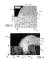
- FIG. 5is a macrograph of a section of an example weld formed with a laser fillet welding operation.
- FIG. 6is a macrograph of a section of a comparative example weld formed with a laser seam welding operation.
- FIG. 1is a flow diagram of method 10 for welding first and second metal parts with a laser fillet welding operation.
- method 10includes steps 12 - 18 , and initially involves forming a corner intersection between at least two overlapping metal parts (step 12 ). This is performed by positioning a first metal part having an edge portion (e.g., a meter plate) on top of a surface of a second metal part (e.g., a blade root) such that the first metal part is flush with the surface of the second metal part. This forms a corner intersection between the edge portion of the first metal part and the surface of the second metal part. The corner intersection may extend around the entire perimeter of the first metal part or around a portion of the perimeter of the first metal part.
- the first metal partPrior to laser welding, the first metal part may be manually resistance tack welded to the second metal part using standard techniques to ensure proper contact between the metal parts.
- a laser beamis then generated and positioned such that it focuses at the corner intersection (i.e., a focal point of the laser beam is located at the corner intersection) (step 14 ).
- Filler materialis then fed to the corner intersection such that the laser beam focuses on, or adjacent to, the filler material (step 16 ).
- the filler materialis a supply of a metal material used to fuse the edge portion of the first metal part to the surface of the second metal part.
- the filler materialmay be supplied in a variety of media, such as powders, granules, wire stock, and rod stock. Suitable materials for the filler material and for the metal parts include laser-weldable metals, such as aluminum, steel, iron, titanium, nickel, cobalt, and alloys thereof.
- the laser beamis then used to laser weld the filler material and the metal parts (step 18 ).
- the energy from the laser beamis absorbed by the filler material, which melts the filler material and allows the melted filler material to fuse to the edge portion of the first metal part and the surface of the second metal part.
- the laser beamis then moved around the entire perimeter of the first metal part while filler material is continuously fed to the laser beam at the corner intersection. This forms a final welded structure where the first metal part is welded to the second metal part around the entire perimeter of the first metal part.
- the filler materialis fed to the corner intersection through a nozzle of a laser system.
- steps 14 - 18 of method 10are performed in a substantially simultaneous manner.
- the laser beammelts the filler material as the filler material is continuously fed from the nozzle to the corner intersection.
- the melted filler materialfuses to the edge portion of the first metal part and the surface of the second metal part, thereby forming the laser fillet weld at the corner intersection.
- the depth of penetration of the weld into the surface of the second metal partis reduced.
- the heat-affected zone of the weldis correspondingly reduced, thereby reducing the formation of cracks and large porous regions in the weld.
- the resulting weldis easy to inspect for proper fusion along the weld path because the weld is located at the corner intersection of the metal parts. This is in contrast to laser seam welds, which are more difficult to inspect because the welds are located between metal parts rather than at a corner intersection.
- FIGS. 2-4illustrate a suitable application of method 10 for producing laser fillet welds with turbine airfoil components.
- FIG. 2is a bottom perspective view of blade root 20 , which is a turbine blade root that is insertable into a dovetail slot (not shown) of a supporting rotor disk (not shown).
- blade root 20includes end wall 22 , inlet apertures 24 a - 24 c , meter plate 26 , lobed walls 28 , and front face 30 .
- End wall 22is a wall segment extending at the base of lobed walls 28 and front face 30 .
- Inlet apertures 24 a - 24 care openings within blade root 20 for receiving cooling air during operation.
- meter plate 26is disposed over end wall 22 and inlet aperture 24 b .
- meter plate 26extends over inlet aperture 24 b for restricting the flow of air through inlet aperture 24 b during operation.
- meter plate 26is secured to end wall 22 with the laser fillet welding operation of method 10 (shown in FIG. 1 ). This secures meter plate 26 to end wall 22 with a laser fillet weld, which reduces penetration depths within end wall 22 , has a reduced heat-affected zone, and is easy to inspect.
- blade root 20is shown with a single meter plate 26 being secured over inlet aperture 24 b
- meter platesmay also be secured over one or more inlet apertures (e.g., inlet apertures 24 a and 24 c ) in a similar manner, and each meter plate may cover one or more inlet apertures.
- meter plate 26is shown in FIG. 1 as being secured to end wall 22
- a similar arrangementmay be used with blade roots having inlet apertures in front face 30 .
- meter plate 26is secured to front face 30 with the laser fillet welding operation of method 10 , which correspondingly reduces penetration depths within front face 30 , has a reduced heat-affected zone, and is easy to inspect.
- FIGS. 3 and 4are expanded side views of end wall 22 and meter plate 26 , which illustrate the laser fillet welding operation of method 10 (shown in FIG. 1 ).
- FIG. 3shows end wall 22 and meter plate 26 prior to welding, where meter plate 26 includes edge portion 32 .
- edge portion 32is disposed on end wall 22 such that edge portion 32 forms corner intersection 34 with end wall 22 . While only a section of edge portion 32 is shown in FIG. 3 , edge portion 32 extends around the entire perimeter of meter plate 26 .
- laser beam 36is generated from a laser system (not shown), and is positioned such that laser beam 36 focuses at corner intersection 34 .
- suitable laser systems for use with the present inventioninclude solid-state laser systems and gas laser systems (e.g., Nd:YAG and CO 2 lasers).
- the energy from laser beam 36is absorbed by filler material 38 , which heats up and melts filler material 38 .
- the energy of laser beam 36also results in localized melting of end wall 22 and edge portion 32 , thereby causing the molten metals of end wall 22 , edge portion 32 , and filler material 38 to mix and fuse together.
- Laser beam 36is then moved around the entire perimeter of meter plate 26 , and filler material 38 is continuously fed to laser beam 36 , thereby forming a laser fillet weld around the entire perimeter of meter plate 26 .
- FIG. 4shows end wall 22 and meter plate 26 after the laser fillet welding operation.
- end wall 22 and edge portion 32 of meter plate 26are fused together at welded joint 40 .
- Welded joint 40is a laser fillet weld that includes a fused agglomerate of metals from end wall 22 , edge portion 32 , and filler material 38 . This secures meter plate 26 to end wall 22 over inlet aperture 24 b for restricting the flow of air through inlet aperture 24 b during operation.
- welded joint 40has a weld leg length (referred to as leg length 42 ) extending from edge portion 32 of meter plate 26 , and a penetration depth (referred to a penetration depth 44 ) extending into end wall 22 .
- leg length 42ranges from about 500 micrometers (about 20 mils) to about 1,300 micrometers (about 50 mils).
- Suitable depths within end wall 22 for penetration depth 32include less than about 25% of the length of leg length 42 , and particularly suitable depths includes less than about 10% of the length of leg length 42 .
- reducing penetration depth 44correspondingly reduces the heat-affected zone of welded joint 40 .
- Reducing the heat-affected zone of welded joint 40reduces the formation of cracks and large porous regions in welded joint 40 , thereby increasing the strength and reliability of welded joint 40 .
- the welded joint 40is easy to inspect for proper fusion along the weld path because welded joint 40 is located at corner intersection 34 of end wall 22 and edge portion 32 .
- Example 1 and Comparative Example Awere each formed at a corner intersection of a meter plate and an end wall of a blade root, which correspond to end wall 22 and meter plate 26 (shown in FIGS. 2-4 ).
- the blade rootwas restrained in a fixture mount and the meter plate was then positioned on a surface of the blade root to form a corner intersection.
- the meter platewas then manually tack welded to the blade root to maintain the meter plate's position and to ensure proper contact between the meter plate and the blade root.
- Filler material(powdered PWA 1447 nickel-based alloy) was then deposited at the corner intersection, and a computer numerical controlled CO 2 laser system (Huffman model HC-205 from Huffman Corporation, Clover, S.C.) was then used to laser fillet weld the entire perimeter of the meter plate. As the laser beam was moved relative to the perimeter of the meter plate, the filler material was continuously fed to the laser beam, thereby forming a laser fillet welded joint around the perimeter of the meter plate.
- a computer numerical controlled CO 2 laser systemHeuffman model HC-205 from Huffman Corporation, Clover, S.C.
- FIG. 5is a macrograph of a section of the welded joint of Example 1, which corresponds to welded joint 40 (shown in FIG. 4 ).
- the reference numerals provided in FIG. 4are correspondingly used in FIG. 5 for ease of discussion.
- End wall 22 , welded joint 40 , and edge portion 32 of meter plate 26can be seen in FIG. 5 .
- the dark portion 46 shown in FIG. 5is an epoxy mold that encased the sectioned welded joint 40 .
- welded joint 40does not penetrate very far below the surface of end wall 22 . In fact, penetration depth 44 of welded joint 40 is less than 10% of its weld leg length 42 from edge portion 32 of meter plate 26 .
- welded joint 40As discussed above, a substantial amount of the energy of laser beam 36 is absorbed by filler material 38 , which reduces penetration depth 44 of welded joint 40 into end wall 22 of blade root 20 . This correspondingly reduces the heat-affected zone of welded joint 40 . This is evidenced in FIG. 5 , where welded joint 40 is substantially free of cracks and large pores or voids. As such, the resulting welded joint 40 of Example 1 provides a strong weld between meter plate 26 and blade root 20 .
- FIG. 6is a macrograph of a section of welded joint 48 of Comparative Example A, which secured end wall 50 of a blade root to edge portion 52 of meter plate 54 .
- End wall 50 and meter plate 54correspond to end wall 22 and meter plate 26 (shown in FIG. 5 ).
- End wall 50 , welded joint 48 (substantially penetrating into end wall 50 ), and edge portion 52 of meter plate 54can be seen in FIG. 6 .
- the dark portions 56 shown in FIG. 6are an epoxy mold that encased the sectioned welded joint 48 .
- the laser seam welding operation of Comparative Example Adid not include filler material 38 .
- the laser beamwas positioned above edge portion 52 of meter plate 54 , thereby directly welding meter plate 54 to end wall 50 of the blade root.
- welded joint 48had a penetration depth 58 that was almost as deep as its weld leg length 60 from edge portion 52 of meter plate 54 .
- This increased the heat-affected zone of welded joint 48, causing cracks 62 and a large void 64 to form in welded joint 48 . Cracks 62 and void 64 accordingly reduced the strength of welded joint 48 of Comparative Example A.
- a comparison of welded joints 40 and 48illustrates the benefits of laser welding meter plate 26 to blade root 20 with the use of filler material 38 , where filler material 38 is fed to corner intersection 34 of meter plate 26 and blade root 20 . Accordingly, the laser fillet welding operation of the present invention provides secure welded joints (e.g., welded joint 40 ) between metal parts that are strong and easy to inspect.
Landscapes
- Physics & Mathematics (AREA)
- Optics & Photonics (AREA)
- Engineering & Computer Science (AREA)
- Plasma & Fusion (AREA)
- Mechanical Engineering (AREA)
- Laser Beam Processing (AREA)
Abstract
Description
Claims (9)
Priority Applications (1)
| Application Number | Priority Date | Filing Date | Title |
|---|---|---|---|
| EP07254530AEP1925391A1 (en) | 2006-11-21 | 2007-11-21 | Laser fillet welding |
Applications Claiming Priority (2)
| Application Number | Priority Date | Filing Date | Title |
|---|---|---|---|
| SG200608084-0 | 2006-11-21 | ||
| SG200608084-0ASG143087A1 (en) | 2006-11-21 | 2006-11-21 | Laser fillet welding |
Publications (2)
| Publication Number | Publication Date |
|---|---|
| US20080118768A1 US20080118768A1 (en) | 2008-05-22 |
| US7767318B2true US7767318B2 (en) | 2010-08-03 |
Family
ID=39417316
Family Applications (1)
| Application Number | Title | Priority Date | Filing Date |
|---|---|---|---|
| US11/699,967Active2028-01-12US7767318B2 (en) | 2006-11-21 | 2007-01-30 | Laser fillet welding |
Country Status (2)
| Country | Link |
|---|---|
| US (1) | US7767318B2 (en) |
| SG (1) | SG143087A1 (en) |
Cited By (3)
| Publication number | Priority date | Publication date | Assignee | Title |
|---|---|---|---|---|
| US20110220622A1 (en)* | 2010-03-09 | 2011-09-15 | United Technologies Corporation | Apparatus and method for preferential formation of weld joint |
| WO2016044592A1 (en)* | 2014-09-19 | 2016-03-24 | Intermetro Industries Corporation | Seismic baseplate |
| US9399262B2 (en) | 2011-12-15 | 2016-07-26 | Lake Region Manufacturing, Inc. | Method of joining titanium and titanium-based alloys to ferrous metals using tantalum |
Families Citing this family (1)
| Publication number | Priority date | Publication date | Assignee | Title |
|---|---|---|---|---|
| SG165202A1 (en)* | 2009-03-25 | 2010-10-28 | United Technologies Corp | Method and apparatus for cleaning a component using microwave radiation |
Citations (50)
| Publication number | Priority date | Publication date | Assignee | Title |
|---|---|---|---|---|
| US2737597A (en) | 1953-05-01 | 1956-03-06 | Louis J Strobino | Protective shield and method of making same |
| JPS5720487A (en) | 1980-07-12 | 1982-02-02 | Hino Motors Ltd | Laser beam irradiation apparatus |
| US4555610A (en) | 1983-09-13 | 1985-11-26 | Data Card Corporation | Laser machining system |
| US4587396A (en) | 1982-12-31 | 1986-05-06 | Laser Industries Ltd. | Control apparatus particularly useful for controlling a laser |
| JPS63115673A (en)* | 1986-10-31 | 1988-05-20 | Inoue Japax Res Inc | Laser welding device |
| JPH01162587A (en)* | 1987-12-19 | 1989-06-27 | Kawasaki Heavy Ind Ltd | Laser welding method |
| JPH02151385A (en) | 1988-11-30 | 1990-06-11 | Tekunisuko:Kk | Weld structure and its manufacture |
| US4947487A (en) | 1989-05-04 | 1990-08-14 | The Jackson Laboratory | Laser beam protective gloves |
| US4972074A (en) | 1989-04-10 | 1990-11-20 | Scott M. Wright | Optical attenuator movement detection system |
| JPH03230885A (en)* | 1990-02-06 | 1991-10-14 | Rohm Co Ltd | Equipment and method for laser beam welding |
| JPH03234393A (en)* | 1990-02-09 | 1991-10-18 | Kobe Steel Ltd | Welding method utilizing laser beam |
| JPH04162974A (en)* | 1990-10-26 | 1992-06-08 | Hitachi Ltd | Laser welding method and laser welding device |
| JPH06289183A (en)* | 1993-04-06 | 1994-10-18 | Hitachi Ltd | Repair of structure in nuclear reactor |
| US5403156A (en) | 1993-10-26 | 1995-04-04 | United Technologies Corporation | Integral meter plate for turbine blade and method |
| US5504300A (en)* | 1994-04-18 | 1996-04-02 | Zimmer, Inc. | Orthopaedic implant and method of making same |
| US5816676A (en) | 1992-08-05 | 1998-10-06 | Koenen Myers; Howard P. | Work glove and illuminator assembly |
| US5902498A (en)* | 1994-08-25 | 1999-05-11 | Qqc, Inc. | Methods of joining metal components and resulting articles particularly automotive torque converter assemblies |
| JPH11347774A (en) | 1998-06-11 | 1999-12-21 | Amada Co Ltd | Handy laser beam head for yag laser |
| US6123506A (en) | 1999-01-20 | 2000-09-26 | Pratt & Whitney Canada Corp. | Diffuser pipe assembly |
| US20010013509A1 (en) | 2000-02-16 | 2001-08-16 | Igor Haschke | Process and device for joining of workpiece parts by means of an energy beam, in particular by means of a laser beam |
| US20020126026A1 (en) | 2001-03-09 | 2002-09-12 | Samsung Electronics Co., Ltd. | Information input system using bio feedback and method thereof |
| US6471475B1 (en) | 2000-07-14 | 2002-10-29 | Pratt & Whitney Canada Corp. | Integrated duct diffuser |
| US20020170893A1 (en) | 2001-05-18 | 2002-11-21 | Z-Laser Optoelektronik Gmbh | Marking device |
| US6501515B1 (en) | 1998-10-13 | 2002-12-31 | Sony Corporation | Remote control system |
| US6531005B1 (en) | 2000-11-17 | 2003-03-11 | General Electric Co. | Heat treatment of weld repaired gas turbine engine components |
| JP2003138935A (en)* | 2001-10-31 | 2003-05-14 | Futaba Industrial Co Ltd | Method of manufacturing vehicle silencer |
| JP2004148333A (en)* | 2002-10-29 | 2004-05-27 | Nippon Steel Corp | Method for improving fatigue strength of lap fillet joints |
| US20040100560A1 (en) | 2002-11-22 | 2004-05-27 | Stavely Donald J. | Tracking digital zoom in a digital video camera |
| US6786696B2 (en) | 2002-05-06 | 2004-09-07 | General Electric Company | Root notched turbine blade |
| US20040189169A1 (en) | 2003-03-28 | 2004-09-30 | Ngk Spark Plug Co., Ltd. | Method for manufacturing a spark plug, and spark plug |
| US20040217266A1 (en) | 2002-01-10 | 2004-11-04 | Bechtel Jon H. | Light sensor configuration |
| US6833525B1 (en) | 1996-08-13 | 2004-12-21 | Carglass Luxembourg Sarl-Zug Branch | Releasing of glazing panels |
| US20040255573A1 (en) | 2003-06-23 | 2004-12-23 | Pratt & Whitney Canada Corp. | Combined exhaust duct and mixer for a gas turbine engine |
| US20050022501A1 (en) | 2003-07-29 | 2005-02-03 | Pratt & Whitney Canada Corp. | Turbofan case and method of making |
| US6875949B2 (en)* | 2003-03-19 | 2005-04-05 | Edison Welding Institute | Method of welding titanium and titanium based alloys to ferrous metals |
| US6919554B2 (en) | 2001-09-05 | 2005-07-19 | Sick Ag | Method and apparatus for securing a hazardous zone surrounding a moving tool |
| US6974306B2 (en) | 2003-07-28 | 2005-12-13 | Pratt & Whitney Canada Corp. | Blade inlet cooling flow deflector apparatus and method |
| US6981845B2 (en) | 2001-04-19 | 2006-01-03 | Snecma Moteurs | Blade for a turbine comprising a cooling air deflector |
| US20060010852A1 (en) | 2004-07-16 | 2006-01-19 | Pratt & Whitney Canada Corp. | Turbine exhaust case and method of making |
| US20060049153A1 (en)* | 2004-09-08 | 2006-03-09 | Cahoon Christopher L | Dual feed laser welding system |
| US7025563B2 (en) | 2003-12-19 | 2006-04-11 | United Technologies Corporation | Stator vane assembly for a gas turbine engine |
| US7030337B2 (en) | 2003-12-19 | 2006-04-18 | Honeywell International, Inc. | Hand-held laser welding wand having removable filler media delivery extension tips |
| US7032904B2 (en) | 2003-08-13 | 2006-04-25 | United Technologies Corporation | Inner air seal anti-rotation device |
| US20060120855A1 (en) | 2004-12-03 | 2006-06-08 | Pratt & Whitney Canada Corp. | Rotor assembly with cooling air deflectors and method |
| US20060174962A1 (en) | 2005-02-04 | 2006-08-10 | Pratt & Whitney Canada Corp. | Tube heat shield and method of making same |
| EP1690630A1 (en) | 2005-02-14 | 2006-08-16 | Gkss-Forschungszentrum Geesthacht Gmbh | Process for joining two metallic workpieces |
| US20060242816A1 (en) | 2005-04-29 | 2006-11-02 | Pratt & Whitney Canada Corp. | Method of manufacturing thin-walled structures |
| US7140952B1 (en) | 2005-09-22 | 2006-11-28 | Pratt & Whitney Canada Corp. | Oxidation protected blade and method of manufacturing |
| US7150797B2 (en)* | 2003-06-20 | 2006-12-19 | Nissan Motor Co., Ltd. | Filler material for use in welding of Mg-contained aluminum alloy die-cast members, welding method, and welded article |
| US20080135530A1 (en)* | 2006-12-11 | 2008-06-12 | General Electric Company | Method of modifying the end wall contour in a turbine using laser consolidation and the turbines derived therefrom |
- 2006
- 2006-11-21SGSG200608084-0Apatent/SG143087A1/enunknown
- 2007
- 2007-01-30USUS11/699,967patent/US7767318B2/enactiveActive
Patent Citations (55)
| Publication number | Priority date | Publication date | Assignee | Title |
|---|---|---|---|---|
| US2737597A (en) | 1953-05-01 | 1956-03-06 | Louis J Strobino | Protective shield and method of making same |
| JPS5720487A (en) | 1980-07-12 | 1982-02-02 | Hino Motors Ltd | Laser beam irradiation apparatus |
| US4587396A (en) | 1982-12-31 | 1986-05-06 | Laser Industries Ltd. | Control apparatus particularly useful for controlling a laser |
| US4555610A (en) | 1983-09-13 | 1985-11-26 | Data Card Corporation | Laser machining system |
| JPS63115673A (en)* | 1986-10-31 | 1988-05-20 | Inoue Japax Res Inc | Laser welding device |
| JPH01162587A (en)* | 1987-12-19 | 1989-06-27 | Kawasaki Heavy Ind Ltd | Laser welding method |
| JPH02151385A (en) | 1988-11-30 | 1990-06-11 | Tekunisuko:Kk | Weld structure and its manufacture |
| US4972074A (en) | 1989-04-10 | 1990-11-20 | Scott M. Wright | Optical attenuator movement detection system |
| US4947487A (en) | 1989-05-04 | 1990-08-14 | The Jackson Laboratory | Laser beam protective gloves |
| JPH03230885A (en)* | 1990-02-06 | 1991-10-14 | Rohm Co Ltd | Equipment and method for laser beam welding |
| JPH03234393A (en)* | 1990-02-09 | 1991-10-18 | Kobe Steel Ltd | Welding method utilizing laser beam |
| JPH04162974A (en)* | 1990-10-26 | 1992-06-08 | Hitachi Ltd | Laser welding method and laser welding device |
| US5816676A (en) | 1992-08-05 | 1998-10-06 | Koenen Myers; Howard P. | Work glove and illuminator assembly |
| JPH06289183A (en)* | 1993-04-06 | 1994-10-18 | Hitachi Ltd | Repair of structure in nuclear reactor |
| US5403156A (en) | 1993-10-26 | 1995-04-04 | United Technologies Corporation | Integral meter plate for turbine blade and method |
| US5504300A (en)* | 1994-04-18 | 1996-04-02 | Zimmer, Inc. | Orthopaedic implant and method of making same |
| US5902498A (en)* | 1994-08-25 | 1999-05-11 | Qqc, Inc. | Methods of joining metal components and resulting articles particularly automotive torque converter assemblies |
| US6833525B1 (en) | 1996-08-13 | 2004-12-21 | Carglass Luxembourg Sarl-Zug Branch | Releasing of glazing panels |
| JPH11347774A (en) | 1998-06-11 | 1999-12-21 | Amada Co Ltd | Handy laser beam head for yag laser |
| US6501515B1 (en) | 1998-10-13 | 2002-12-31 | Sony Corporation | Remote control system |
| US6123506A (en) | 1999-01-20 | 2000-09-26 | Pratt & Whitney Canada Corp. | Diffuser pipe assembly |
| US20010013509A1 (en) | 2000-02-16 | 2001-08-16 | Igor Haschke | Process and device for joining of workpiece parts by means of an energy beam, in particular by means of a laser beam |
| US6596962B2 (en)* | 2000-02-16 | 2003-07-22 | Michael Anders | Process and device for joining of workpiece parts by means of an energy beam, in particular by means of a laser beam |
| US6471475B1 (en) | 2000-07-14 | 2002-10-29 | Pratt & Whitney Canada Corp. | Integrated duct diffuser |
| US6531005B1 (en) | 2000-11-17 | 2003-03-11 | General Electric Co. | Heat treatment of weld repaired gas turbine engine components |
| US20020126026A1 (en) | 2001-03-09 | 2002-09-12 | Samsung Electronics Co., Ltd. | Information input system using bio feedback and method thereof |
| US6981845B2 (en) | 2001-04-19 | 2006-01-03 | Snecma Moteurs | Blade for a turbine comprising a cooling air deflector |
| US20020170893A1 (en) | 2001-05-18 | 2002-11-21 | Z-Laser Optoelektronik Gmbh | Marking device |
| US6919554B2 (en) | 2001-09-05 | 2005-07-19 | Sick Ag | Method and apparatus for securing a hazardous zone surrounding a moving tool |
| JP2003138935A (en)* | 2001-10-31 | 2003-05-14 | Futaba Industrial Co Ltd | Method of manufacturing vehicle silencer |
| US20040217266A1 (en) | 2002-01-10 | 2004-11-04 | Bechtel Jon H. | Light sensor configuration |
| US6786696B2 (en) | 2002-05-06 | 2004-09-07 | General Electric Company | Root notched turbine blade |
| JP2004148333A (en)* | 2002-10-29 | 2004-05-27 | Nippon Steel Corp | Method for improving fatigue strength of lap fillet joints |
| US20040100560A1 (en) | 2002-11-22 | 2004-05-27 | Stavely Donald J. | Tracking digital zoom in a digital video camera |
| US6875949B2 (en)* | 2003-03-19 | 2005-04-05 | Edison Welding Institute | Method of welding titanium and titanium based alloys to ferrous metals |
| US20040189169A1 (en) | 2003-03-28 | 2004-09-30 | Ngk Spark Plug Co., Ltd. | Method for manufacturing a spark plug, and spark plug |
| US7150797B2 (en)* | 2003-06-20 | 2006-12-19 | Nissan Motor Co., Ltd. | Filler material for use in welding of Mg-contained aluminum alloy die-cast members, welding method, and welded article |
| US20040255573A1 (en) | 2003-06-23 | 2004-12-23 | Pratt & Whitney Canada Corp. | Combined exhaust duct and mixer for a gas turbine engine |
| US7043898B2 (en) | 2003-06-23 | 2006-05-16 | Pratt & Whitney Canada Corp. | Combined exhaust duct and mixer for a gas turbine engine |
| US6974306B2 (en) | 2003-07-28 | 2005-12-13 | Pratt & Whitney Canada Corp. | Blade inlet cooling flow deflector apparatus and method |
| US20050109013A1 (en) | 2003-07-29 | 2005-05-26 | Pratt & Whitney Canada Corp. | Turbofan case and method of making |
| US20050022501A1 (en) | 2003-07-29 | 2005-02-03 | Pratt & Whitney Canada Corp. | Turbofan case and method of making |
| US7032904B2 (en) | 2003-08-13 | 2006-04-25 | United Technologies Corporation | Inner air seal anti-rotation device |
| US7025563B2 (en) | 2003-12-19 | 2006-04-11 | United Technologies Corporation | Stator vane assembly for a gas turbine engine |
| US7030337B2 (en) | 2003-12-19 | 2006-04-18 | Honeywell International, Inc. | Hand-held laser welding wand having removable filler media delivery extension tips |
| US7100358B2 (en) | 2004-07-16 | 2006-09-05 | Pratt & Whitney Canada Corp. | Turbine exhaust case and method of making |
| US20060260127A1 (en) | 2004-07-16 | 2006-11-23 | Pratt & Whitney Canada Corp. | Turbine exhaust case and method of making |
| US20060010852A1 (en) | 2004-07-16 | 2006-01-19 | Pratt & Whitney Canada Corp. | Turbine exhaust case and method of making |
| US20060049153A1 (en)* | 2004-09-08 | 2006-03-09 | Cahoon Christopher L | Dual feed laser welding system |
| US20060120855A1 (en) | 2004-12-03 | 2006-06-08 | Pratt & Whitney Canada Corp. | Rotor assembly with cooling air deflectors and method |
| US20060174962A1 (en) | 2005-02-04 | 2006-08-10 | Pratt & Whitney Canada Corp. | Tube heat shield and method of making same |
| EP1690630A1 (en) | 2005-02-14 | 2006-08-16 | Gkss-Forschungszentrum Geesthacht Gmbh | Process for joining two metallic workpieces |
| US20060242816A1 (en) | 2005-04-29 | 2006-11-02 | Pratt & Whitney Canada Corp. | Method of manufacturing thin-walled structures |
| US7140952B1 (en) | 2005-09-22 | 2006-11-28 | Pratt & Whitney Canada Corp. | Oxidation protected blade and method of manufacturing |
| US20080135530A1 (en)* | 2006-12-11 | 2008-06-12 | General Electric Company | Method of modifying the end wall contour in a turbine using laser consolidation and the turbines derived therefrom |
Non-Patent Citations (1)
| Title |
|---|
| Official Search Report and Written Opinion of the European Patent Office in counterpart foreign Application No. EP 07254530 filed Nov. 21, 2007. |
Cited By (6)
| Publication number | Priority date | Publication date | Assignee | Title |
|---|---|---|---|---|
| US20110220622A1 (en)* | 2010-03-09 | 2011-09-15 | United Technologies Corporation | Apparatus and method for preferential formation of weld joint |
| US8304093B2 (en)* | 2010-03-09 | 2012-11-06 | United Technologies Corporation | Apparatus and method for preferential formation of weld joint |
| US9399262B2 (en) | 2011-12-15 | 2016-07-26 | Lake Region Manufacturing, Inc. | Method of joining titanium and titanium-based alloys to ferrous metals using tantalum |
| WO2016044592A1 (en)* | 2014-09-19 | 2016-03-24 | Intermetro Industries Corporation | Seismic baseplate |
| CN106714617A (en)* | 2014-09-19 | 2017-05-24 | 因特梅特罗工业公司 | Seismic Substrate |
| US10743663B2 (en) | 2014-09-19 | 2020-08-18 | Intermetro Industries Corporation | Seismic baseplate |
Also Published As
| Publication number | Publication date |
|---|---|
| SG143087A1 (en) | 2008-06-27 |
| US20080118768A1 (en) | 2008-05-22 |
Similar Documents
| Publication | Publication Date | Title |
|---|---|---|
| EP1738858B1 (en) | Shimmed laser beam butt welding process without using a backing for joining superalloys for gas turbine applications | |
| RU2624884C2 (en) | Localized repair of the component from superalloy | |
| JP5154505B2 (en) | How to make blisk | |
| US7146725B2 (en) | Repair of combustion turbine components | |
| JP6159147B2 (en) | Hybrid laser arc welding process and apparatus | |
| EP2246144B1 (en) | A method of high-powered laser beam welding of articles using a metallic shim produding from the surfaces of the articles ; Assembly therefore | |
| JP5736135B2 (en) | Double laser beam welding method for first and second filler metals | |
| EP1689553B1 (en) | Methods for repair of single crystal superalloys by laser welding and products thereof | |
| CN105408056B (en) | Repair of substrates with component-supported filler | |
| EP2567774A1 (en) | Hybrid laser arc welding system and method | |
| US20170320174A1 (en) | Method for producing a turbine engine part | |
| US9186740B2 (en) | Projection resistance brazing of superalloys | |
| US9273562B2 (en) | Projection resistance welding of superalloys | |
| US7767318B2 (en) | Laser fillet welding | |
| JP6838832B2 (en) | Welding filler for superalloys | |
| US9284848B2 (en) | Method for integrally connecting blades and disks in order to form a blade-disk unit, as well as correspondingly produced blade-disk unit | |
| US20240316643A1 (en) | Support strategy for thin-walled additive structure | |
| CN106513998B (en) | A kind of method for laser welding of titanium alloy blade | |
| EP1925391A1 (en) | Laser fillet welding | |
| JP2017094382A (en) | Laser welded joint | |
| Hui-Chi et al. | High energy beam welding processes in manufacturing | |
| Hui-Chi et al. | High-Energy Beam Welding Processes in Manufacturing | |
| Hoult et al. | High-speed keyhole welding of steels using< 500-W CO2 lasers | |
| JP2003227350A (en) | Manufacturing method of turbine blade and turbine blade using this method | |
| Qi et al. | Application of laser powder deposition for turbine blade tip cap freeform fabrication |
Legal Events
| Date | Code | Title | Description |
|---|---|---|---|
| AS | Assignment | Owner name:AVENTIS PHARMA DEUTSCHLAND GMBH, GERMANY Free format text:ASSIGNMENT OF ASSIGNORS INTEREST;ASSIGNORS:GLOMBIK, HEINER;FRICK, WENDELIN;SCHAEFER, HANS-LUDWIG;AND OTHERS;REEL/FRAME:018553/0008 Effective date:20021209 | |
| AS | Assignment | Owner name:UNITED TECHNOLOGIES CORPORATION, CONNECTICUT Free format text:ASSIGNMENT OF ASSIGNORS INTEREST;ASSIGNORS:CHENG, KENNY;LUAH, KOK HAI;REEL/FRAME:018864/0719 Effective date:20070129 | |
| AS | Assignment | Owner name:TURBINE OVERHAUL SERVICES PTE LTD, SINGAPORE Free format text:CORRECTIVE ASSIGNMENT TO CORRECT THE NAME AND ADDRESS OF THE RECEIVING PARTY. DOCUMENT PREVIOUSLY RECORDED AT REEL 018864 FRAME 0719;ASSIGNORS:CHENG, KENNY;LUAH, KOK HAI;REEL/FRAME:018954/0789 Effective date:20070129 | |
| STCF | Information on status: patent grant | Free format text:PATENTED CASE | |
| FPAY | Fee payment | Year of fee payment:4 | |
| MAFP | Maintenance fee payment | Free format text:PAYMENT OF MAINTENANCE FEE, 8TH YEAR, LARGE ENTITY (ORIGINAL EVENT CODE: M1552) Year of fee payment:8 | |
| MAFP | Maintenance fee payment | Free format text:PAYMENT OF MAINTENANCE FEE, 12TH YEAR, LARGE ENTITY (ORIGINAL EVENT CODE: M1553); ENTITY STATUS OF PATENT OWNER: LARGE ENTITY Year of fee payment:12 |