US7766969B2 - Modular progressive implant for a joint articulation surface - Google Patents
Modular progressive implant for a joint articulation surfaceDownload PDFInfo
- Publication number
- US7766969B2 US7766969B2US11/557,399US55739906AUS7766969B2US 7766969 B2US7766969 B2US 7766969B2US 55739906 AUS55739906 AUS 55739906AUS 7766969 B2US7766969 B2US 7766969B2
- Authority
- US
- United States
- Prior art keywords
- tray
- keel
- implant
- passageway
- opening
- Prior art date
- Legal status (The legal status is an assumption and is not a legal conclusion. Google has not performed a legal analysis and makes no representation as to the accuracy of the status listed.)
- Expired - Fee Related
Links
Images


Classifications
- A—HUMAN NECESSITIES
- A61—MEDICAL OR VETERINARY SCIENCE; HYGIENE
- A61F—FILTERS IMPLANTABLE INTO BLOOD VESSELS; PROSTHESES; DEVICES PROVIDING PATENCY TO, OR PREVENTING COLLAPSING OF, TUBULAR STRUCTURES OF THE BODY, e.g. STENTS; ORTHOPAEDIC, NURSING OR CONTRACEPTIVE DEVICES; FOMENTATION; TREATMENT OR PROTECTION OF EYES OR EARS; BANDAGES, DRESSINGS OR ABSORBENT PADS; FIRST-AID KITS
- A61F2/00—Filters implantable into blood vessels; Prostheses, i.e. artificial substitutes or replacements for parts of the body; Appliances for connecting them with the body; Devices providing patency to, or preventing collapsing of, tubular structures of the body, e.g. stents
- A61F2/02—Prostheses implantable into the body
- A61F2/30—Joints
- A61F2/30721—Accessories
- A61F2/30749—Fixation appliances for connecting prostheses to the body
- A—HUMAN NECESSITIES
- A61—MEDICAL OR VETERINARY SCIENCE; HYGIENE
- A61F—FILTERS IMPLANTABLE INTO BLOOD VESSELS; PROSTHESES; DEVICES PROVIDING PATENCY TO, OR PREVENTING COLLAPSING OF, TUBULAR STRUCTURES OF THE BODY, e.g. STENTS; ORTHOPAEDIC, NURSING OR CONTRACEPTIVE DEVICES; FOMENTATION; TREATMENT OR PROTECTION OF EYES OR EARS; BANDAGES, DRESSINGS OR ABSORBENT PADS; FIRST-AID KITS
- A61F2/00—Filters implantable into blood vessels; Prostheses, i.e. artificial substitutes or replacements for parts of the body; Appliances for connecting them with the body; Devices providing patency to, or preventing collapsing of, tubular structures of the body, e.g. stents
- A61F2/02—Prostheses implantable into the body
- A61F2/30—Joints
- A61F2/38—Joints for elbows or knees
- A61F2/389—Tibial components
- A—HUMAN NECESSITIES
- A61—MEDICAL OR VETERINARY SCIENCE; HYGIENE
- A61B—DIAGNOSIS; SURGERY; IDENTIFICATION
- A61B17/00—Surgical instruments, devices or methods
- A61B17/56—Surgical instruments or methods for treatment of bones or joints; Devices specially adapted therefor
- A61B17/58—Surgical instruments or methods for treatment of bones or joints; Devices specially adapted therefor for osteosynthesis, e.g. bone plates, screws or setting implements
- A61B17/68—Internal fixation devices, including fasteners and spinal fixators, even if a part thereof projects from the skin
- A61B17/80—Cortical plates, i.e. bone plates; Instruments for holding or positioning cortical plates, or for compressing bones attached to cortical plates
- A61B17/8033—Cortical plates, i.e. bone plates; Instruments for holding or positioning cortical plates, or for compressing bones attached to cortical plates having indirect contact with screw heads, or having contact with screw heads maintained with the aid of additional components, e.g. nuts, wedges or head covers
- A61B17/8047—Cortical plates, i.e. bone plates; Instruments for holding or positioning cortical plates, or for compressing bones attached to cortical plates having indirect contact with screw heads, or having contact with screw heads maintained with the aid of additional components, e.g. nuts, wedges or head covers wherein the additional element surrounds the screw head in the plate hole
- A—HUMAN NECESSITIES
- A61—MEDICAL OR VETERINARY SCIENCE; HYGIENE
- A61F—FILTERS IMPLANTABLE INTO BLOOD VESSELS; PROSTHESES; DEVICES PROVIDING PATENCY TO, OR PREVENTING COLLAPSING OF, TUBULAR STRUCTURES OF THE BODY, e.g. STENTS; ORTHOPAEDIC, NURSING OR CONTRACEPTIVE DEVICES; FOMENTATION; TREATMENT OR PROTECTION OF EYES OR EARS; BANDAGES, DRESSINGS OR ABSORBENT PADS; FIRST-AID KITS
- A61F2/00—Filters implantable into blood vessels; Prostheses, i.e. artificial substitutes or replacements for parts of the body; Appliances for connecting them with the body; Devices providing patency to, or preventing collapsing of, tubular structures of the body, e.g. stents
- A61F2/02—Prostheses implantable into the body
- A61F2/30—Joints
- A61F2/32—Joints for the hip
- A61F2/34—Acetabular cups
- A—HUMAN NECESSITIES
- A61—MEDICAL OR VETERINARY SCIENCE; HYGIENE
- A61F—FILTERS IMPLANTABLE INTO BLOOD VESSELS; PROSTHESES; DEVICES PROVIDING PATENCY TO, OR PREVENTING COLLAPSING OF, TUBULAR STRUCTURES OF THE BODY, e.g. STENTS; ORTHOPAEDIC, NURSING OR CONTRACEPTIVE DEVICES; FOMENTATION; TREATMENT OR PROTECTION OF EYES OR EARS; BANDAGES, DRESSINGS OR ABSORBENT PADS; FIRST-AID KITS
- A61F2/00—Filters implantable into blood vessels; Prostheses, i.e. artificial substitutes or replacements for parts of the body; Appliances for connecting them with the body; Devices providing patency to, or preventing collapsing of, tubular structures of the body, e.g. stents
- A61F2/02—Prostheses implantable into the body
- A61F2/30—Joints
- A61F2/38—Joints for elbows or knees
- A61F2/3804—Joints for elbows or knees for elbows
- A—HUMAN NECESSITIES
- A61—MEDICAL OR VETERINARY SCIENCE; HYGIENE
- A61F—FILTERS IMPLANTABLE INTO BLOOD VESSELS; PROSTHESES; DEVICES PROVIDING PATENCY TO, OR PREVENTING COLLAPSING OF, TUBULAR STRUCTURES OF THE BODY, e.g. STENTS; ORTHOPAEDIC, NURSING OR CONTRACEPTIVE DEVICES; FOMENTATION; TREATMENT OR PROTECTION OF EYES OR EARS; BANDAGES, DRESSINGS OR ABSORBENT PADS; FIRST-AID KITS
- A61F2/00—Filters implantable into blood vessels; Prostheses, i.e. artificial substitutes or replacements for parts of the body; Appliances for connecting them with the body; Devices providing patency to, or preventing collapsing of, tubular structures of the body, e.g. stents
- A61F2/02—Prostheses implantable into the body
- A61F2/30—Joints
- A61F2/40—Joints for shoulders
- A—HUMAN NECESSITIES
- A61—MEDICAL OR VETERINARY SCIENCE; HYGIENE
- A61F—FILTERS IMPLANTABLE INTO BLOOD VESSELS; PROSTHESES; DEVICES PROVIDING PATENCY TO, OR PREVENTING COLLAPSING OF, TUBULAR STRUCTURES OF THE BODY, e.g. STENTS; ORTHOPAEDIC, NURSING OR CONTRACEPTIVE DEVICES; FOMENTATION; TREATMENT OR PROTECTION OF EYES OR EARS; BANDAGES, DRESSINGS OR ABSORBENT PADS; FIRST-AID KITS
- A61F2/00—Filters implantable into blood vessels; Prostheses, i.e. artificial substitutes or replacements for parts of the body; Appliances for connecting them with the body; Devices providing patency to, or preventing collapsing of, tubular structures of the body, e.g. stents
- A61F2/02—Prostheses implantable into the body
- A61F2/30—Joints
- A61F2/42—Joints for wrists or ankles; for hands, e.g. fingers; for feet, e.g. toes
- A61F2/4202—Joints for wrists or ankles; for hands, e.g. fingers; for feet, e.g. toes for ankles
- A—HUMAN NECESSITIES
- A61—MEDICAL OR VETERINARY SCIENCE; HYGIENE
- A61F—FILTERS IMPLANTABLE INTO BLOOD VESSELS; PROSTHESES; DEVICES PROVIDING PATENCY TO, OR PREVENTING COLLAPSING OF, TUBULAR STRUCTURES OF THE BODY, e.g. STENTS; ORTHOPAEDIC, NURSING OR CONTRACEPTIVE DEVICES; FOMENTATION; TREATMENT OR PROTECTION OF EYES OR EARS; BANDAGES, DRESSINGS OR ABSORBENT PADS; FIRST-AID KITS
- A61F2/00—Filters implantable into blood vessels; Prostheses, i.e. artificial substitutes or replacements for parts of the body; Appliances for connecting them with the body; Devices providing patency to, or preventing collapsing of, tubular structures of the body, e.g. stents
- A61F2/02—Prostheses implantable into the body
- A61F2/30—Joints
- A61F2/42—Joints for wrists or ankles; for hands, e.g. fingers; for feet, e.g. toes
- A61F2/4261—Joints for wrists or ankles; for hands, e.g. fingers; for feet, e.g. toes for wrists
- A—HUMAN NECESSITIES
- A61—MEDICAL OR VETERINARY SCIENCE; HYGIENE
- A61F—FILTERS IMPLANTABLE INTO BLOOD VESSELS; PROSTHESES; DEVICES PROVIDING PATENCY TO, OR PREVENTING COLLAPSING OF, TUBULAR STRUCTURES OF THE BODY, e.g. STENTS; ORTHOPAEDIC, NURSING OR CONTRACEPTIVE DEVICES; FOMENTATION; TREATMENT OR PROTECTION OF EYES OR EARS; BANDAGES, DRESSINGS OR ABSORBENT PADS; FIRST-AID KITS
- A61F2/00—Filters implantable into blood vessels; Prostheses, i.e. artificial substitutes or replacements for parts of the body; Appliances for connecting them with the body; Devices providing patency to, or preventing collapsing of, tubular structures of the body, e.g. stents
- A61F2/02—Prostheses implantable into the body
- A61F2/30—Joints
- A61F2/46—Special tools for implanting artificial joints
- A61F2/4637—Special tools for implanting artificial joints for connecting or disconnecting two parts of a prosthesis
- A—HUMAN NECESSITIES
- A61—MEDICAL OR VETERINARY SCIENCE; HYGIENE
- A61F—FILTERS IMPLANTABLE INTO BLOOD VESSELS; PROSTHESES; DEVICES PROVIDING PATENCY TO, OR PREVENTING COLLAPSING OF, TUBULAR STRUCTURES OF THE BODY, e.g. STENTS; ORTHOPAEDIC, NURSING OR CONTRACEPTIVE DEVICES; FOMENTATION; TREATMENT OR PROTECTION OF EYES OR EARS; BANDAGES, DRESSINGS OR ABSORBENT PADS; FIRST-AID KITS
- A61F2/00—Filters implantable into blood vessels; Prostheses, i.e. artificial substitutes or replacements for parts of the body; Appliances for connecting them with the body; Devices providing patency to, or preventing collapsing of, tubular structures of the body, e.g. stents
- A61F2/02—Prostheses implantable into the body
- A61F2/30—Joints
- A61F2002/30001—Additional features of subject-matter classified in A61F2/28, A61F2/30 and subgroups thereof
- A61F2002/30108—Shapes
- A61F2002/3011—Cross-sections or two-dimensional shapes
- A61F2002/30138—Convex polygonal shapes
- A61F2002/30153—Convex polygonal shapes rectangular
- A—HUMAN NECESSITIES
- A61—MEDICAL OR VETERINARY SCIENCE; HYGIENE
- A61F—FILTERS IMPLANTABLE INTO BLOOD VESSELS; PROSTHESES; DEVICES PROVIDING PATENCY TO, OR PREVENTING COLLAPSING OF, TUBULAR STRUCTURES OF THE BODY, e.g. STENTS; ORTHOPAEDIC, NURSING OR CONTRACEPTIVE DEVICES; FOMENTATION; TREATMENT OR PROTECTION OF EYES OR EARS; BANDAGES, DRESSINGS OR ABSORBENT PADS; FIRST-AID KITS
- A61F2/00—Filters implantable into blood vessels; Prostheses, i.e. artificial substitutes or replacements for parts of the body; Appliances for connecting them with the body; Devices providing patency to, or preventing collapsing of, tubular structures of the body, e.g. stents
- A61F2/02—Prostheses implantable into the body
- A61F2/30—Joints
- A61F2002/30001—Additional features of subject-matter classified in A61F2/28, A61F2/30 and subgroups thereof
- A61F2002/30316—The prosthesis having different structural features at different locations within the same prosthesis; Connections between prosthetic parts; Special structural features of bone or joint prostheses not otherwise provided for
- A61F2002/30329—Connections or couplings between prosthetic parts, e.g. between modular parts; Connecting elements
- A61F2002/30331—Connections or couplings between prosthetic parts, e.g. between modular parts; Connecting elements made by longitudinally pushing a protrusion into a complementarily-shaped recess, e.g. held by friction fit
- A61F2002/30362—Connections or couplings between prosthetic parts, e.g. between modular parts; Connecting elements made by longitudinally pushing a protrusion into a complementarily-shaped recess, e.g. held by friction fit with possibility of relative movement between the protrusion and the recess
- A61F2002/30364—Rotation about the common longitudinal axis
- A61F2002/30367—Rotation about the common longitudinal axis with additional means for preventing said rotation
- A—HUMAN NECESSITIES
- A61—MEDICAL OR VETERINARY SCIENCE; HYGIENE
- A61F—FILTERS IMPLANTABLE INTO BLOOD VESSELS; PROSTHESES; DEVICES PROVIDING PATENCY TO, OR PREVENTING COLLAPSING OF, TUBULAR STRUCTURES OF THE BODY, e.g. STENTS; ORTHOPAEDIC, NURSING OR CONTRACEPTIVE DEVICES; FOMENTATION; TREATMENT OR PROTECTION OF EYES OR EARS; BANDAGES, DRESSINGS OR ABSORBENT PADS; FIRST-AID KITS
- A61F2/00—Filters implantable into blood vessels; Prostheses, i.e. artificial substitutes or replacements for parts of the body; Appliances for connecting them with the body; Devices providing patency to, or preventing collapsing of, tubular structures of the body, e.g. stents
- A61F2/02—Prostheses implantable into the body
- A61F2/30—Joints
- A61F2002/30001—Additional features of subject-matter classified in A61F2/28, A61F2/30 and subgroups thereof
- A61F2002/30316—The prosthesis having different structural features at different locations within the same prosthesis; Connections between prosthetic parts; Special structural features of bone or joint prostheses not otherwise provided for
- A61F2002/30329—Connections or couplings between prosthetic parts, e.g. between modular parts; Connecting elements
- A61F2002/30331—Connections or couplings between prosthetic parts, e.g. between modular parts; Connecting elements made by longitudinally pushing a protrusion into a complementarily-shaped recess, e.g. held by friction fit
- A61F2002/30362—Connections or couplings between prosthetic parts, e.g. between modular parts; Connecting elements made by longitudinally pushing a protrusion into a complementarily-shaped recess, e.g. held by friction fit with possibility of relative movement between the protrusion and the recess
- A61F2002/3037—Translation along the common longitudinal axis, e.g. piston
- A61F2002/30372—Translation along the common longitudinal axis, e.g. piston with additional means for limiting said translation
- A—HUMAN NECESSITIES
- A61—MEDICAL OR VETERINARY SCIENCE; HYGIENE
- A61F—FILTERS IMPLANTABLE INTO BLOOD VESSELS; PROSTHESES; DEVICES PROVIDING PATENCY TO, OR PREVENTING COLLAPSING OF, TUBULAR STRUCTURES OF THE BODY, e.g. STENTS; ORTHOPAEDIC, NURSING OR CONTRACEPTIVE DEVICES; FOMENTATION; TREATMENT OR PROTECTION OF EYES OR EARS; BANDAGES, DRESSINGS OR ABSORBENT PADS; FIRST-AID KITS
- A61F2/00—Filters implantable into blood vessels; Prostheses, i.e. artificial substitutes or replacements for parts of the body; Appliances for connecting them with the body; Devices providing patency to, or preventing collapsing of, tubular structures of the body, e.g. stents
- A61F2/02—Prostheses implantable into the body
- A61F2/30—Joints
- A61F2002/30001—Additional features of subject-matter classified in A61F2/28, A61F2/30 and subgroups thereof
- A61F2002/30316—The prosthesis having different structural features at different locations within the same prosthesis; Connections between prosthetic parts; Special structural features of bone or joint prostheses not otherwise provided for
- A61F2002/30329—Connections or couplings between prosthetic parts, e.g. between modular parts; Connecting elements
- A61F2002/30383—Connections or couplings between prosthetic parts, e.g. between modular parts; Connecting elements made by laterally inserting a protrusion, e.g. a rib into a complementarily-shaped groove
- A61F2002/30385—Connections or couplings between prosthetic parts, e.g. between modular parts; Connecting elements made by laterally inserting a protrusion, e.g. a rib into a complementarily-shaped groove the rib and groove having non-parallel, e.g. conically-tapered, cooperating sides, e.g. having a trapezoidal front cross-section
- A—HUMAN NECESSITIES
- A61—MEDICAL OR VETERINARY SCIENCE; HYGIENE
- A61F—FILTERS IMPLANTABLE INTO BLOOD VESSELS; PROSTHESES; DEVICES PROVIDING PATENCY TO, OR PREVENTING COLLAPSING OF, TUBULAR STRUCTURES OF THE BODY, e.g. STENTS; ORTHOPAEDIC, NURSING OR CONTRACEPTIVE DEVICES; FOMENTATION; TREATMENT OR PROTECTION OF EYES OR EARS; BANDAGES, DRESSINGS OR ABSORBENT PADS; FIRST-AID KITS
- A61F2/00—Filters implantable into blood vessels; Prostheses, i.e. artificial substitutes or replacements for parts of the body; Appliances for connecting them with the body; Devices providing patency to, or preventing collapsing of, tubular structures of the body, e.g. stents
- A61F2/02—Prostheses implantable into the body
- A61F2/30—Joints
- A61F2002/30001—Additional features of subject-matter classified in A61F2/28, A61F2/30 and subgroups thereof
- A61F2002/30316—The prosthesis having different structural features at different locations within the same prosthesis; Connections between prosthetic parts; Special structural features of bone or joint prostheses not otherwise provided for
- A61F2002/30329—Connections or couplings between prosthetic parts, e.g. between modular parts; Connecting elements
- A61F2002/30383—Connections or couplings between prosthetic parts, e.g. between modular parts; Connecting elements made by laterally inserting a protrusion, e.g. a rib into a complementarily-shaped groove
- A61F2002/30387—Dovetail connection
- A—HUMAN NECESSITIES
- A61—MEDICAL OR VETERINARY SCIENCE; HYGIENE
- A61F—FILTERS IMPLANTABLE INTO BLOOD VESSELS; PROSTHESES; DEVICES PROVIDING PATENCY TO, OR PREVENTING COLLAPSING OF, TUBULAR STRUCTURES OF THE BODY, e.g. STENTS; ORTHOPAEDIC, NURSING OR CONTRACEPTIVE DEVICES; FOMENTATION; TREATMENT OR PROTECTION OF EYES OR EARS; BANDAGES, DRESSINGS OR ABSORBENT PADS; FIRST-AID KITS
- A61F2/00—Filters implantable into blood vessels; Prostheses, i.e. artificial substitutes or replacements for parts of the body; Appliances for connecting them with the body; Devices providing patency to, or preventing collapsing of, tubular structures of the body, e.g. stents
- A61F2/02—Prostheses implantable into the body
- A61F2/30—Joints
- A61F2002/30001—Additional features of subject-matter classified in A61F2/28, A61F2/30 and subgroups thereof
- A61F2002/30316—The prosthesis having different structural features at different locations within the same prosthesis; Connections between prosthetic parts; Special structural features of bone or joint prostheses not otherwise provided for
- A61F2002/30329—Connections or couplings between prosthetic parts, e.g. between modular parts; Connecting elements
- A61F2002/30405—Connections or couplings between prosthetic parts, e.g. between modular parts; Connecting elements made by screwing complementary threads machined on the parts themselves
- A—HUMAN NECESSITIES
- A61—MEDICAL OR VETERINARY SCIENCE; HYGIENE
- A61F—FILTERS IMPLANTABLE INTO BLOOD VESSELS; PROSTHESES; DEVICES PROVIDING PATENCY TO, OR PREVENTING COLLAPSING OF, TUBULAR STRUCTURES OF THE BODY, e.g. STENTS; ORTHOPAEDIC, NURSING OR CONTRACEPTIVE DEVICES; FOMENTATION; TREATMENT OR PROTECTION OF EYES OR EARS; BANDAGES, DRESSINGS OR ABSORBENT PADS; FIRST-AID KITS
- A61F2/00—Filters implantable into blood vessels; Prostheses, i.e. artificial substitutes or replacements for parts of the body; Appliances for connecting them with the body; Devices providing patency to, or preventing collapsing of, tubular structures of the body, e.g. stents
- A61F2/02—Prostheses implantable into the body
- A61F2/30—Joints
- A61F2002/30001—Additional features of subject-matter classified in A61F2/28, A61F2/30 and subgroups thereof
- A61F2002/30316—The prosthesis having different structural features at different locations within the same prosthesis; Connections between prosthetic parts; Special structural features of bone or joint prostheses not otherwise provided for
- A61F2002/30329—Connections or couplings between prosthetic parts, e.g. between modular parts; Connecting elements
- A61F2002/30433—Connections or couplings between prosthetic parts, e.g. between modular parts; Connecting elements using additional screws, bolts, dowels, rivets or washers e.g. connecting screws
- A—HUMAN NECESSITIES
- A61—MEDICAL OR VETERINARY SCIENCE; HYGIENE
- A61F—FILTERS IMPLANTABLE INTO BLOOD VESSELS; PROSTHESES; DEVICES PROVIDING PATENCY TO, OR PREVENTING COLLAPSING OF, TUBULAR STRUCTURES OF THE BODY, e.g. STENTS; ORTHOPAEDIC, NURSING OR CONTRACEPTIVE DEVICES; FOMENTATION; TREATMENT OR PROTECTION OF EYES OR EARS; BANDAGES, DRESSINGS OR ABSORBENT PADS; FIRST-AID KITS
- A61F2/00—Filters implantable into blood vessels; Prostheses, i.e. artificial substitutes or replacements for parts of the body; Appliances for connecting them with the body; Devices providing patency to, or preventing collapsing of, tubular structures of the body, e.g. stents
- A61F2/02—Prostheses implantable into the body
- A61F2/30—Joints
- A61F2002/30001—Additional features of subject-matter classified in A61F2/28, A61F2/30 and subgroups thereof
- A61F2002/30316—The prosthesis having different structural features at different locations within the same prosthesis; Connections between prosthetic parts; Special structural features of bone or joint prostheses not otherwise provided for
- A61F2002/30329—Connections or couplings between prosthetic parts, e.g. between modular parts; Connecting elements
- A61F2002/30476—Connections or couplings between prosthetic parts, e.g. between modular parts; Connecting elements locked by an additional locking mechanism
- A61F2002/30507—Connections or couplings between prosthetic parts, e.g. between modular parts; Connecting elements locked by an additional locking mechanism using a threaded locking member, e.g. a locking screw or a set screw
- A—HUMAN NECESSITIES
- A61—MEDICAL OR VETERINARY SCIENCE; HYGIENE
- A61F—FILTERS IMPLANTABLE INTO BLOOD VESSELS; PROSTHESES; DEVICES PROVIDING PATENCY TO, OR PREVENTING COLLAPSING OF, TUBULAR STRUCTURES OF THE BODY, e.g. STENTS; ORTHOPAEDIC, NURSING OR CONTRACEPTIVE DEVICES; FOMENTATION; TREATMENT OR PROTECTION OF EYES OR EARS; BANDAGES, DRESSINGS OR ABSORBENT PADS; FIRST-AID KITS
- A61F2/00—Filters implantable into blood vessels; Prostheses, i.e. artificial substitutes or replacements for parts of the body; Appliances for connecting them with the body; Devices providing patency to, or preventing collapsing of, tubular structures of the body, e.g. stents
- A61F2/02—Prostheses implantable into the body
- A61F2/30—Joints
- A61F2002/30001—Additional features of subject-matter classified in A61F2/28, A61F2/30 and subgroups thereof
- A61F2002/30316—The prosthesis having different structural features at different locations within the same prosthesis; Connections between prosthetic parts; Special structural features of bone or joint prostheses not otherwise provided for
- A61F2002/30329—Connections or couplings between prosthetic parts, e.g. between modular parts; Connecting elements
- A61F2002/30476—Connections or couplings between prosthetic parts, e.g. between modular parts; Connecting elements locked by an additional locking mechanism
- A61F2002/30517—Connections or couplings between prosthetic parts, e.g. between modular parts; Connecting elements locked by an additional locking mechanism using a locking plate
- A—HUMAN NECESSITIES
- A61—MEDICAL OR VETERINARY SCIENCE; HYGIENE
- A61F—FILTERS IMPLANTABLE INTO BLOOD VESSELS; PROSTHESES; DEVICES PROVIDING PATENCY TO, OR PREVENTING COLLAPSING OF, TUBULAR STRUCTURES OF THE BODY, e.g. STENTS; ORTHOPAEDIC, NURSING OR CONTRACEPTIVE DEVICES; FOMENTATION; TREATMENT OR PROTECTION OF EYES OR EARS; BANDAGES, DRESSINGS OR ABSORBENT PADS; FIRST-AID KITS
- A61F2/00—Filters implantable into blood vessels; Prostheses, i.e. artificial substitutes or replacements for parts of the body; Appliances for connecting them with the body; Devices providing patency to, or preventing collapsing of, tubular structures of the body, e.g. stents
- A61F2/02—Prostheses implantable into the body
- A61F2/30—Joints
- A61F2002/30001—Additional features of subject-matter classified in A61F2/28, A61F2/30 and subgroups thereof
- A61F2002/30316—The prosthesis having different structural features at different locations within the same prosthesis; Connections between prosthetic parts; Special structural features of bone or joint prostheses not otherwise provided for
- A61F2002/30535—Special structural features of bone or joint prostheses not otherwise provided for
- A61F2002/30604—Special structural features of bone or joint prostheses not otherwise provided for modular
- A—HUMAN NECESSITIES
- A61—MEDICAL OR VETERINARY SCIENCE; HYGIENE
- A61F—FILTERS IMPLANTABLE INTO BLOOD VESSELS; PROSTHESES; DEVICES PROVIDING PATENCY TO, OR PREVENTING COLLAPSING OF, TUBULAR STRUCTURES OF THE BODY, e.g. STENTS; ORTHOPAEDIC, NURSING OR CONTRACEPTIVE DEVICES; FOMENTATION; TREATMENT OR PROTECTION OF EYES OR EARS; BANDAGES, DRESSINGS OR ABSORBENT PADS; FIRST-AID KITS
- A61F2/00—Filters implantable into blood vessels; Prostheses, i.e. artificial substitutes or replacements for parts of the body; Appliances for connecting them with the body; Devices providing patency to, or preventing collapsing of, tubular structures of the body, e.g. stents
- A61F2/02—Prostheses implantable into the body
- A61F2/30—Joints
- A61F2/30767—Special external or bone-contacting surface, e.g. coating for improving bone ingrowth
- A61F2/30771—Special external or bone-contacting surface, e.g. coating for improving bone ingrowth applied in original prostheses, e.g. holes or grooves
- A61F2002/30772—Apertures or holes, e.g. of circular cross section
- A61F2002/3079—Stepped or enlarged apertures, e.g. having discrete diameter changes
- A—HUMAN NECESSITIES
- A61—MEDICAL OR VETERINARY SCIENCE; HYGIENE
- A61F—FILTERS IMPLANTABLE INTO BLOOD VESSELS; PROSTHESES; DEVICES PROVIDING PATENCY TO, OR PREVENTING COLLAPSING OF, TUBULAR STRUCTURES OF THE BODY, e.g. STENTS; ORTHOPAEDIC, NURSING OR CONTRACEPTIVE DEVICES; FOMENTATION; TREATMENT OR PROTECTION OF EYES OR EARS; BANDAGES, DRESSINGS OR ABSORBENT PADS; FIRST-AID KITS
- A61F2/00—Filters implantable into blood vessels; Prostheses, i.e. artificial substitutes or replacements for parts of the body; Appliances for connecting them with the body; Devices providing patency to, or preventing collapsing of, tubular structures of the body, e.g. stents
- A61F2/02—Prostheses implantable into the body
- A61F2/30—Joints
- A61F2/30767—Special external or bone-contacting surface, e.g. coating for improving bone ingrowth
- A61F2/30771—Special external or bone-contacting surface, e.g. coating for improving bone ingrowth applied in original prostheses, e.g. holes or grooves
- A61F2002/30795—Blind bores, e.g. of circular cross-section
- A61F2002/30797—Blind bores, e.g. of circular cross-section internally-threaded
- A—HUMAN NECESSITIES
- A61—MEDICAL OR VETERINARY SCIENCE; HYGIENE
- A61F—FILTERS IMPLANTABLE INTO BLOOD VESSELS; PROSTHESES; DEVICES PROVIDING PATENCY TO, OR PREVENTING COLLAPSING OF, TUBULAR STRUCTURES OF THE BODY, e.g. STENTS; ORTHOPAEDIC, NURSING OR CONTRACEPTIVE DEVICES; FOMENTATION; TREATMENT OR PROTECTION OF EYES OR EARS; BANDAGES, DRESSINGS OR ABSORBENT PADS; FIRST-AID KITS
- A61F2/00—Filters implantable into blood vessels; Prostheses, i.e. artificial substitutes or replacements for parts of the body; Appliances for connecting them with the body; Devices providing patency to, or preventing collapsing of, tubular structures of the body, e.g. stents
- A61F2/02—Prostheses implantable into the body
- A61F2/30—Joints
- A61F2/30767—Special external or bone-contacting surface, e.g. coating for improving bone ingrowth
- A61F2/30771—Special external or bone-contacting surface, e.g. coating for improving bone ingrowth applied in original prostheses, e.g. holes or grooves
- A61F2002/3085—Special external or bone-contacting surface, e.g. coating for improving bone ingrowth applied in original prostheses, e.g. holes or grooves with a threaded, e.g. self-tapping, bone-engaging surface, e.g. external surface
- A61F2002/30871—Trapezoidal threads
- A—HUMAN NECESSITIES
- A61—MEDICAL OR VETERINARY SCIENCE; HYGIENE
- A61F—FILTERS IMPLANTABLE INTO BLOOD VESSELS; PROSTHESES; DEVICES PROVIDING PATENCY TO, OR PREVENTING COLLAPSING OF, TUBULAR STRUCTURES OF THE BODY, e.g. STENTS; ORTHOPAEDIC, NURSING OR CONTRACEPTIVE DEVICES; FOMENTATION; TREATMENT OR PROTECTION OF EYES OR EARS; BANDAGES, DRESSINGS OR ABSORBENT PADS; FIRST-AID KITS
- A61F2/00—Filters implantable into blood vessels; Prostheses, i.e. artificial substitutes or replacements for parts of the body; Appliances for connecting them with the body; Devices providing patency to, or preventing collapsing of, tubular structures of the body, e.g. stents
- A61F2/02—Prostheses implantable into the body
- A61F2/30—Joints
- A61F2/30767—Special external or bone-contacting surface, e.g. coating for improving bone ingrowth
- A61F2/30771—Special external or bone-contacting surface, e.g. coating for improving bone ingrowth applied in original prostheses, e.g. holes or grooves
- A61F2002/3085—Special external or bone-contacting surface, e.g. coating for improving bone ingrowth applied in original prostheses, e.g. holes or grooves with a threaded, e.g. self-tapping, bone-engaging surface, e.g. external surface
- A61F2002/30873—Threadings machined on non-cylindrical external surfaces
- A—HUMAN NECESSITIES
- A61—MEDICAL OR VETERINARY SCIENCE; HYGIENE
- A61F—FILTERS IMPLANTABLE INTO BLOOD VESSELS; PROSTHESES; DEVICES PROVIDING PATENCY TO, OR PREVENTING COLLAPSING OF, TUBULAR STRUCTURES OF THE BODY, e.g. STENTS; ORTHOPAEDIC, NURSING OR CONTRACEPTIVE DEVICES; FOMENTATION; TREATMENT OR PROTECTION OF EYES OR EARS; BANDAGES, DRESSINGS OR ABSORBENT PADS; FIRST-AID KITS
- A61F2/00—Filters implantable into blood vessels; Prostheses, i.e. artificial substitutes or replacements for parts of the body; Appliances for connecting them with the body; Devices providing patency to, or preventing collapsing of, tubular structures of the body, e.g. stents
- A61F2/02—Prostheses implantable into the body
- A61F2/30—Joints
- A61F2/32—Joints for the hip
- A61F2/34—Acetabular cups
- A61F2002/3401—Acetabular cups with radial apertures, e.g. radial bores for receiving fixation screws
- A—HUMAN NECESSITIES
- A61—MEDICAL OR VETERINARY SCIENCE; HYGIENE
- A61F—FILTERS IMPLANTABLE INTO BLOOD VESSELS; PROSTHESES; DEVICES PROVIDING PATENCY TO, OR PREVENTING COLLAPSING OF, TUBULAR STRUCTURES OF THE BODY, e.g. STENTS; ORTHOPAEDIC, NURSING OR CONTRACEPTIVE DEVICES; FOMENTATION; TREATMENT OR PROTECTION OF EYES OR EARS; BANDAGES, DRESSINGS OR ABSORBENT PADS; FIRST-AID KITS
- A61F2/00—Filters implantable into blood vessels; Prostheses, i.e. artificial substitutes or replacements for parts of the body; Appliances for connecting them with the body; Devices providing patency to, or preventing collapsing of, tubular structures of the body, e.g. stents
- A61F2/02—Prostheses implantable into the body
- A61F2/30—Joints
- A61F2/46—Special tools for implanting artificial joints
- A61F2/4603—Special tools for implanting artificial joints for insertion or extraction of endoprosthetic joints or of accessories thereof
- A61F2002/4629—Special tools for implanting artificial joints for insertion or extraction of endoprosthetic joints or of accessories thereof connected to the endoprosthesis or implant via a threaded connection
- A—HUMAN NECESSITIES
- A61—MEDICAL OR VETERINARY SCIENCE; HYGIENE
- A61F—FILTERS IMPLANTABLE INTO BLOOD VESSELS; PROSTHESES; DEVICES PROVIDING PATENCY TO, OR PREVENTING COLLAPSING OF, TUBULAR STRUCTURES OF THE BODY, e.g. STENTS; ORTHOPAEDIC, NURSING OR CONTRACEPTIVE DEVICES; FOMENTATION; TREATMENT OR PROTECTION OF EYES OR EARS; BANDAGES, DRESSINGS OR ABSORBENT PADS; FIRST-AID KITS
- A61F2/00—Filters implantable into blood vessels; Prostheses, i.e. artificial substitutes or replacements for parts of the body; Appliances for connecting them with the body; Devices providing patency to, or preventing collapsing of, tubular structures of the body, e.g. stents
- A61F2/02—Prostheses implantable into the body
- A61F2/30—Joints
- A61F2/46—Special tools for implanting artificial joints
- A61F2/4637—Special tools for implanting artificial joints for connecting or disconnecting two parts of a prosthesis
- A61F2002/4638—Tools for performing screwing, e.g. nut or screwdrivers, or particular adaptations therefor
- A—HUMAN NECESSITIES
- A61—MEDICAL OR VETERINARY SCIENCE; HYGIENE
- A61F—FILTERS IMPLANTABLE INTO BLOOD VESSELS; PROSTHESES; DEVICES PROVIDING PATENCY TO, OR PREVENTING COLLAPSING OF, TUBULAR STRUCTURES OF THE BODY, e.g. STENTS; ORTHOPAEDIC, NURSING OR CONTRACEPTIVE DEVICES; FOMENTATION; TREATMENT OR PROTECTION OF EYES OR EARS; BANDAGES, DRESSINGS OR ABSORBENT PADS; FIRST-AID KITS
- A61F2/00—Filters implantable into blood vessels; Prostheses, i.e. artificial substitutes or replacements for parts of the body; Appliances for connecting them with the body; Devices providing patency to, or preventing collapsing of, tubular structures of the body, e.g. stents
- A61F2/02—Prostheses implantable into the body
- A61F2/30—Joints
- A61F2/46—Special tools for implanting artificial joints
- A61F2/4637—Special tools for implanting artificial joints for connecting or disconnecting two parts of a prosthesis
- A61F2002/4641—Special tools for implanting artificial joints for connecting or disconnecting two parts of a prosthesis for disconnecting
- A—HUMAN NECESSITIES
- A61—MEDICAL OR VETERINARY SCIENCE; HYGIENE
- A61F—FILTERS IMPLANTABLE INTO BLOOD VESSELS; PROSTHESES; DEVICES PROVIDING PATENCY TO, OR PREVENTING COLLAPSING OF, TUBULAR STRUCTURES OF THE BODY, e.g. STENTS; ORTHOPAEDIC, NURSING OR CONTRACEPTIVE DEVICES; FOMENTATION; TREATMENT OR PROTECTION OF EYES OR EARS; BANDAGES, DRESSINGS OR ABSORBENT PADS; FIRST-AID KITS
- A61F2220/00—Fixations or connections for prostheses classified in groups A61F2/00 - A61F2/26 or A61F2/82 or A61F9/00 or A61F11/00 or subgroups thereof
- A61F2220/0025—Connections or couplings between prosthetic parts, e.g. between modular parts; Connecting elements
- A61F2220/0033—Connections or couplings between prosthetic parts, e.g. between modular parts; Connecting elements made by longitudinally pushing a protrusion into a complementary-shaped recess, e.g. held by friction fit
- A—HUMAN NECESSITIES
- A61—MEDICAL OR VETERINARY SCIENCE; HYGIENE
- A61F—FILTERS IMPLANTABLE INTO BLOOD VESSELS; PROSTHESES; DEVICES PROVIDING PATENCY TO, OR PREVENTING COLLAPSING OF, TUBULAR STRUCTURES OF THE BODY, e.g. STENTS; ORTHOPAEDIC, NURSING OR CONTRACEPTIVE DEVICES; FOMENTATION; TREATMENT OR PROTECTION OF EYES OR EARS; BANDAGES, DRESSINGS OR ABSORBENT PADS; FIRST-AID KITS
- A61F2220/00—Fixations or connections for prostheses classified in groups A61F2/00 - A61F2/26 or A61F2/82 or A61F9/00 or A61F11/00 or subgroups thereof
- A61F2220/0025—Connections or couplings between prosthetic parts, e.g. between modular parts; Connecting elements
- A61F2220/0041—Connections or couplings between prosthetic parts, e.g. between modular parts; Connecting elements using additional screws, bolts, dowels or rivets, e.g. connecting screws
- A—HUMAN NECESSITIES
- A61—MEDICAL OR VETERINARY SCIENCE; HYGIENE
- A61F—FILTERS IMPLANTABLE INTO BLOOD VESSELS; PROSTHESES; DEVICES PROVIDING PATENCY TO, OR PREVENTING COLLAPSING OF, TUBULAR STRUCTURES OF THE BODY, e.g. STENTS; ORTHOPAEDIC, NURSING OR CONTRACEPTIVE DEVICES; FOMENTATION; TREATMENT OR PROTECTION OF EYES OR EARS; BANDAGES, DRESSINGS OR ABSORBENT PADS; FIRST-AID KITS
- A61F2230/00—Geometry of prostheses classified in groups A61F2/00 - A61F2/26 or A61F2/82 or A61F9/00 or A61F11/00 or subgroups thereof
- A61F2230/0002—Two-dimensional shapes, e.g. cross-sections
- A61F2230/0017—Angular shapes
- A61F2230/0019—Angular shapes rectangular
- A—HUMAN NECESSITIES
- A61—MEDICAL OR VETERINARY SCIENCE; HYGIENE
- A61F—FILTERS IMPLANTABLE INTO BLOOD VESSELS; PROSTHESES; DEVICES PROVIDING PATENCY TO, OR PREVENTING COLLAPSING OF, TUBULAR STRUCTURES OF THE BODY, e.g. STENTS; ORTHOPAEDIC, NURSING OR CONTRACEPTIVE DEVICES; FOMENTATION; TREATMENT OR PROTECTION OF EYES OR EARS; BANDAGES, DRESSINGS OR ABSORBENT PADS; FIRST-AID KITS
- A61F2310/00—Prostheses classified in A61F2/28 or A61F2/30 - A61F2/44 being constructed from or coated with a particular material
- A61F2310/00005—The prosthesis being constructed from a particular material
- A61F2310/00011—Metals or alloys
- A61F2310/00017—Iron- or Fe-based alloys, e.g. stainless steel
- A—HUMAN NECESSITIES
- A61—MEDICAL OR VETERINARY SCIENCE; HYGIENE
- A61F—FILTERS IMPLANTABLE INTO BLOOD VESSELS; PROSTHESES; DEVICES PROVIDING PATENCY TO, OR PREVENTING COLLAPSING OF, TUBULAR STRUCTURES OF THE BODY, e.g. STENTS; ORTHOPAEDIC, NURSING OR CONTRACEPTIVE DEVICES; FOMENTATION; TREATMENT OR PROTECTION OF EYES OR EARS; BANDAGES, DRESSINGS OR ABSORBENT PADS; FIRST-AID KITS
- A61F2310/00—Prostheses classified in A61F2/28 or A61F2/30 - A61F2/44 being constructed from or coated with a particular material
- A61F2310/00005—The prosthesis being constructed from a particular material
- A61F2310/00011—Metals or alloys
- A61F2310/00023—Titanium or titanium-based alloys, e.g. Ti-Ni alloys
- A—HUMAN NECESSITIES
- A61—MEDICAL OR VETERINARY SCIENCE; HYGIENE
- A61F—FILTERS IMPLANTABLE INTO BLOOD VESSELS; PROSTHESES; DEVICES PROVIDING PATENCY TO, OR PREVENTING COLLAPSING OF, TUBULAR STRUCTURES OF THE BODY, e.g. STENTS; ORTHOPAEDIC, NURSING OR CONTRACEPTIVE DEVICES; FOMENTATION; TREATMENT OR PROTECTION OF EYES OR EARS; BANDAGES, DRESSINGS OR ABSORBENT PADS; FIRST-AID KITS
- A61F2310/00—Prostheses classified in A61F2/28 or A61F2/30 - A61F2/44 being constructed from or coated with a particular material
- A61F2310/00005—The prosthesis being constructed from a particular material
- A61F2310/00179—Ceramics or ceramic-like structures
Definitions
- the present inventionrelates to prosthetic joints and, more particularly, to modular interchangeable bone implants to replace articular bone surfaces and methods for installing and replacing the implants.
- the human bodyhas a variety of movable orthopedic joints such as the knee joint, hip joint, shoulder joint, and the like. These joints are formed by the intersection of two bones.
- the intersecting end of each bonehas one or more condyles consisting of a smooth articular surface that is comprised of cartilage.
- the knee jointcomprises two generally rounded condyles, i.e., lateral and medial condyles that are located at the lower or distal end of the femur. These femoral condyles are disposed above corresponding lateral and medial condyles located at the upper or proximal end of the tibia.
- a joint replacement or arthroplastycomprises cutting off or resecting the femoral condyles at the distal end of the femur and the tibial condyles at the proximal end of the tibia.
- Complementary artificial implantsreferred to as total condylar implants, are then mounted on the distal end of the femur and the proximal end of the tibia. Where only a portion of a joint is damaged, a partial joint arthroplasty can be performed.
- one or more artificial implantsreplace only a portion of a joint.
- a portion of a jointFor example, where only one femoral or tibial condyle of the knee joint has been injured, only one of the injured lateral or medial femoral condyles is resected. The corresponding one of the lateral or medial tibial condyles is also resected. Implants replacing only a single condyle, referred to as uni-condylar implants, are mounted on the resected area of the femur and tibia.
- Another shortcoming with current implantsis an inability to easily replace the implant once the implant has been installed.
- a partial joint arthroplastymay be required, and a uni-condylar implant installed. Months or years later, the rest of the joint may deteriorate and the uni-condylar implant must be replaced with a total condylar implant. This occurs frequently with the knee.
- replacing a uni-condylar implant with a total condylar implantrequires removing the entire uni-condylar implant from the bone (including the anchoring system), drilling or otherwise creating a new hole in the bone to anchor the total joint implant, then installing the total joint implant with a new anchor. Because a new anchoring hole and anchor are required, more bone must be drilled into or otherwise removed, causing more pain for the patient, an increased possibility of infection, a longer recovery time, and generally more risk.
- implants and related methods for mounting the implants on an articular surface of a jointwhich enable easier fitting, alignment, testing, and/or replacement of implants.
- implants and related methodswhich enable easy replacement of uni-condylar implants with total condylar implants.
- FIG. 1is a perspective view of the proximal end of a tibia
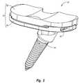
- FIG. 2is a perspective view of a total condylar implant according to one embodiment of the present invention that can be placed on the proximal end of the tibia shown in FIG. 1 ;
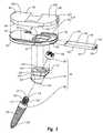
- FIG. 3is an exploded perspective view of the implant shown in FIG. 2 ;
- FIG. 4is a top perspective view of the tray of the implant shown in FIG. 3 ;
- FIG. 5is a cross-sectional top view of the tray shown in FIG. 4 , with a fastener inserted therein;
- FIG. 6is a bottom perspective view of the bearing member of the implant shown in FIG. 3 ;
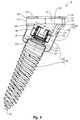
- FIG. 7is a cross sectional side view of the keel shown in FIG. 3 ;
- FIG. 8is a cross-sectional side view of an anchor used in the implant shown in FIG. 3 ;
- FIG. 9is a cross sectional side view of the implant shown in FIG. 2 mounted on the tibia shown in FIG. 1 ;
- FIG. 10is a perspective view of a total condylar implant (shown without a bearing member) according to an alternative embodiment of the present invention.
- FIG. 11is a bottom perspective view of a tray used in the implant shown in FIG. 10 ;
- FIG. 12is a perspective view of an uni-condylar implant according to one embodiment of the present invention that can be placed on the proximal end of the tibia shown in FIG. 1 ;
- FIG. 13is a cross-sectional top view of a tray used in the uni-condylar implant shown in FIG. 12 ;
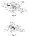
- FIG. 14is a cross-sectional side view of an alternative embodiment of an inventive implant mounted on the distal end of a femur with a fastener partially inserted;
- FIG. 15is a cross-sectional side view of another alternative embodiment of an inventive implant mounted on a pelvis
- FIG. 16is a cross-sectional side view of a partially assembled anchor used in the implant shown in FIG. 15 ;
- FIG. 17is a cross-sectional side view of the anchor shown in FIG. 15 , fully assembled.
- the present inventionrelates to implants for mounting at an articulation surface of an orthopedic joint and related methods.
- articulation surfaceand “natural articulation surface” are broadly intended to include all natural articular surfaces of a bone forming a portion of an orthopedic joint and all articulation wear surfaces of a bone forming a portion of an orthopedic joint which are produced as a result of wear, trauma, disease, or other causes which remove all or a portion of the natural articular surface.
- the implants and methods of the present inventioncan be used for mounting an implant on virtually any articulation surface of any orthopedic joint in a human or other mammal.
- the implants and methods of the present inventioncan be used in association with resurfacing an articulation surface of a knee joint, ankle joint, hip joint, shoulder joint, elbow joint, wrist joint, interphalangeal joint, or other joints.
- the implantscan be mounted on the proximal end and distal end of the femur, tibia, humerus, radius, and ulna, and on the articular surfaces of the scapula, pelvis, bones within the foot and hand, and other bone articular surfaces.
- the implants and methods of the present inventioncan be used in facilitating a partial joint arthroplasty or a total joint arthroplasty.
- the implants and/or methodsare designed to be modular such that either the articulation bearing surface of the implant can be positioned on the bone after an anchor is inserted into the bone or the anchor can be inserted into the bone after the articulation bearing surface of the implant has been positioned on the bone. This ability allows for greater ease in adjustment and fitting of the implant at the time of initial placement and for greater ease in replacement of the implant.
- FIG. 1Depicted in FIG. 1 is a proximal end 10 of a tibia 12 .
- Proximal end 10has a lateral side 14 and a medial side 16 which each extend between an anterior side 18 and a posterior side 20 .
- Proximal end 10further comprises a lateral condyle 22 and a medial condyle 24 .
- Lateral condyle 22terminates proximally at a lateral facet 26 of a superior articular surface of tibia 12 while medial condyle 24 terminates proximally at medial facet 28 of a superior articular surface of tibia 12 .
- tibia 12 shown in FIG. 1corresponds to a left leg
- the tibia of the right leghas a complimentary configuration and that the methods and apparatus of this specific example are equally applicable thereto.
- implant 30comprises a bearing assembly 32 attached to an anchor 34 that is adapted for mounting into a bone. More specifically, as depicted in FIG. 3 , bearing assembly 32 comprises a tray 36 with a bearing member 38 adapted for mounting thereon. Anchor 34 projects down from tray 36 , and means for securing tray 36 to anchor 34 are provided. In the depicted embodiment, the means for securing comprises a fastener 40 .
- tray 36has a top surface 42 and an opposing bone apposition surface 44 with a perimeter edge 46 extending therebetween.
- Top surface 42 and bone apposition surface 44are substantially flat and extend between a first end 48 and an opposing second end 50 .
- a notch 51extends between top surface 42 and bone apposition surface 44 and is formed on perimeter edge 46 at a substantially central location between opposing ends 48 and 50 .
- Top surface 42is configured to receive bearing member 38 .
- a first channel 52 A and a second channel 52 Bare formed on top surface 42 .
- First channel 52 Ais recessed on top surface 42 so as to extend from perimeter edge 46 at second end 50 to toward first end 48 .
- first channel 52 Ahas a tapered, substantially V-shaped configuration.
- First channel 52 Ais bounded by a substantially flat floor 54 having a sidewall 56 upstanding therefrom.
- Sidewall 56comprises a recess groove 58 which extends along floor 54 and an outwardly projecting lip 60 which projects along top surface 42 .
- the opposing sidewalls 56 of channel 52 Aform a mortise or guide to receive and secure a key projecting down from bearing member 38 as will be discussed below in greater detail.
- Second channel 52 Bis spaced apart from first channel 52 A but also extends from second end 50 to toward first end 48 of tray 36 . In contrast to first channel 52 A, however, second channel 52 B continuously extends along perimeter edge 46 . Common elements between channels 52 A and 52 B are identified by like reference characters. In alternative embodiments, it is appreciated that tray 36 can be formed with only one channel or three or more channels. Furthermore, the size, position, and configuration of the various channels can be varied. For example, second channel 52 B can have the same configuration as first channel 52 A. The general concept is that the channels are configured to that they can receivably engage bearing member 38 . In this regard, side wall 56 can also have a variety of different configurations.
- proximal end 10 of tibia 12( FIG. 1 ) is resected to form a tibial plateau.
- Bone apposition surface 44 of tray 36is configured to sit on the tibial plateau and typically has a configuration complementary thereto.
- bone apposition surface 44can be substantially flat or can be curved such as having a convex curvature or concave curvature.
- groovescan be formed on bone apposition surface 44 and/or projections can be formed extending from bone apposition surface 44 .
- the projectionscan comprise fins, sharpened spikes, or the like.
- Such projectionscan be configured to penetrate into the bone or to be received within slots formed on the tibial plateau.
- the projectionscan also serve to strengthen tray 36 by increasing the bending moment of inertia of tray 36 .
- one or more pocketscan be formed on bone apposition surface 44 in which a porous bone ingrowth material can be disposed.
- Tray 36also bounds an opening 62 which extends completely through tray 36 between top surface 42 and bone apposition surface 44 .
- Opening 62is bounded by a sidewall 64 extending between top surface 42 and bone apposition surface 44 .
- opening 62is large enough for all of anchor 34 to completely pass through opening 62 .
- opening 62is depicted as generally rectangular in shape, other shapes may alternatively be used, so long as opening 62 allows anchor 34 to be received into opening 62 , as discussed below.
- opening 62can be generally circular, oval, polygonal, irregular or any other shape.
- opening 62is shown being disposed at or toward second end 50 of tray 36 . However, it is appreciated that opening 62 can alternatively be placed at or toward first end 48 or at other locations.
- a first passageway 66 and a second passageway 68are horizontally formed in tray 36 so as to communicate with opening 62 .
- Passageways 66 and 68are formed to receive and secure the means for securing tray 36 to anchor 34 .
- One embodiment of such meanscomprises fastener 40 as depicted in FIG. 5 .
- Alternative means for securingare discussed below.
- First passageway 66is bounded by an internal surface 70 that extends between perimeter edge 46 at the second end 50 of tray 36 to a sidewall 72 of opening 62 . As a result, first passageway 66 forms a tunnel that is open at opposing ends.
- Second passageway 68is bounded by an internal surface 76 and extends a distance from a medial sidewall 74 of opening 62 to toward first end 48 of tray 36 . Second passageway 68 terminates at a closed distal end 78 . Although depicted as terminating within tray 36 , it is appreciated that second passageway 68 may alternatively extend to perimeter edge 46 at the first end 48 oftray 36 .
- First and second passageways 66 and 68have a height h and width w that are substantially constant along the entire length of both passageways.
- passageways 66 and 68are shaped as slots with rounded side surfaces 80 .
- side surfaces 80are alternatively shaped, such as being squared off, trapezoidal or the like.
- First and second passageways 66 and 68are longitudinally and vertically aligned to be able to receive fastener 40 when fastener 40 is inserted into tray 36 through first passageway 66 , as shown in FIG. 5 .
- first and second passageways 66 and 68are depicted as slots, it is appreciated that other passageway shapes may alternatively be employed in other embodiments depending on the means provided for locking tray 36 to anchor 34 .
- first and second passageways 66 and 68can be round, oval or rectangular when viewed transversally.
- First and second passageways 66 and 68can have internal surfaces 70 that are smooth or threaded.
- first and second passageways 66 and 68can be disposed on the first end 48 of tray 36 if opening 62 is formed on the first end 48 of tray 36 .
- First and second passageways 66 and 68can also be tapered to allow for a greater press-fit connection with fastener 40 .
- first and second passageways 66 and 68are shaped to be able to receive the means for securing tray 36 to anchor 34 .
- bearing member 38comprises a top articular surface 82 and a bottom surface 84 which each extend between a first end 86 and an opposing second end 88 .
- a perimeter edge 87extends between top articular surface 82 and bottom surface 84 with a notch 79 being formed thereon.
- Top surface 82is configured to interact with a femoral component.
- top surface 82has a pair of spaced apart concave pockets 83 A and 83 B that are each adapted to receive a condyle from a femoral component.
- top surface 82can have a variety of different configurations depending on the design for the corresponding implant that is to interact with top surface 82 .
- Bottom surface 84 of bearing member 38has a configuration substantially complementary to top surface 42 of tray 36 .
- bottom surface 84includes a substantially flat floor 81 having a pair of elongated keys 90 A and 90 B projecting therefrom.
- Key 90 Ahas a configuration substantially complementary to channel 52 A ( FIG. 4 ) of tray 36 and includes a sidewall 92 extending from floor 81 to an end face 85 .
- Sidewall 92has a recessed groove 93 extending along floor 81 and an outwardly projecting lip 95 extending along end face 85 .
- Sidewall 92 of key 90 Ais substantially complementary to sidewall 56 of channel 52 A such that key 90 A forms a tenon that can slide into channel 52 A to form a secure, releasable connection therewith.
- An elongated second key 90 Balso projects from floor 81 and has a sidewall 92 . Key 90 B is configured to slide into channel 52 B of tray 36 and engage with sidewall 56 thereof, thereby further securing bearing member 38 to tray 36 . Alternative embodiments as discussed with tray 36 are also applicable to bearing member 38 .
- Channels 52 A and B and keys 90 A and Bare one embodiment of means for connecting bearing member 38 to tray 36 .
- different techniquessuch as snap fit, press fit, or mechanical connector can be used to secure bearing member 38 and tray 36 together.
- Bearing member 38may be of any suitable biocompatible material.
- bearing member 38is comprised of a polymeric material although composites, metals, and other materials can also be used.
- anchor 34comprises a keel 94 with a stem 96 that projects downward therefrom.
- a locking nut 98is used to secure stem 96 to keel 94 .
- Anchor 34is used to secure implant 30 to proximal end 10 of tibia 12 .
- keel 94comprises an upper portion 100 that terminates at a top surface 104 and a lower portion 102 that terminates at a bottom surface 105 .
- keel 94also has an interior surface 109 that bounds a bore 126 extending through keel 94 between top surface 104 and bottom surface 105 .
- Radially inwardly projecting from interior surface 109 at a location toward bottom surface 105is an annular flange 111 .
- Flange 111forms a seat against which locking nut 98 can bias.
- upper portion 100is used to mount and secure keel 94 to tray 36 while lower portion 102 is used to mount and secure keel 94 to stem 96 .
- upper and lower portions 100 and 102are integrally formed. In other embodiments upper and lower portions 100 and 102 can be separate and discrete components that are connected together.
- Upper portion 100is configured to fit within opening 62 in tray 36 and can selectively pass therethrough if desired.
- Upper portion 100is shown having a transverse cross section that is substantially complementary to the transverse cross section of opening 62 . That is, upper portion 100 is rectangularly shaped when viewed perpendicularly to top surface 104 so as to substantially match the shape of opening 62 .
- Top surface 104 of upper portion 100is substantially planar so that it can sit flush with top surface 42 of tray 36 .
- upper portion 100has a sidewall 106 that is substantially the same thickness as tray 36 at opening 62 .
- a third passageway 110transversely extends all the way through upper portion 100 of keel 94 so as to intersect with bore 126 .
- third passageway 110is bounded by an internal surface 112 and extends from a first opening 114 on sidewall 106 of keel 94 to a second opening 118 on the opposing side of keel 94 .
- Third passageway 110is sized and shaped to substantially align with first and second passageways 66 and 68 of tray 36 when upper portion 100 of keel 94 is received within opening 62 of tray 36 . Aligned passageways 66 , 68 , and 110 combine to form a contiguous passageway which can receive fastener 40 .
- third passageway 110has substantially the same height h and width w as first and second passageways 66 and 68 .
- Third passageway 110is depicted as a slot with rounded side surfaces to match first and second passageways 66 and 68 . It is appreciated that other passageway shapes may alternatively be employed in third passageway in other embodiments to match alternatively shaped first and second passageways 66 and 68 .
- third passageway 110can be substantially round, oval or rectangular when viewed transversally.
- Third passageway 110can have walls that are smooth or threaded to match first and second passageways 66 and 68 .
- lower portion 102 of keel 94is used to mount and secure keel 94 to stem 96 .
- Lower portion 102angles down from upper portion 100 .
- Lower portion 102is substantially rectangular where it connects to upper portion 100 and transitions to being substantially cylindrical in shape at a bottom end 122 .
- a central longitudinal axis 113extends through lower portion 102 and the portion of bore 126 disposed therein.
- lower portion 102is formed so that an inside angle ⁇ is formed between top surface 104 of keel 94 and longitudinal axis 113 that is less than 80° and more commonly less than 70° or 60°.
- lower portion 102 and bore 126can be positioned so that the angle ⁇ is 90°.
- stem 96is an elongated member having a proximal end 134 and an opposing distal end 136 .
- Stem 96includes a head 130 formed at proximal end 134 and a shank 132 projecting from head 130 .
- Shank 132tapers to a point at distal end 136 and has threads formed thereon so that shank 132 can be threaded or screwed into tibia 12 so as to securely engage tibia 12 .
- shank 132has a larger outer diameter than head 130 so that an annular shoulder 117 is formed thereat.
- Head 130is threaded so as to enable locking nut 98 to be screwed thereon, as described below.
- proximal end 134terminates at a terminal end face 119 in which a socket 121 is formed.
- Socket 121is non-circular to that a driver (not shown) can be received within socket 121 and then rotated so as to rotate stem 96 .
- socket 121has a polygonal configuration although other non-circular shapes can also be used.
- a stem having a polygonal or other non-circular transverse cross sectioncan project from end face 119 for engaging with a driver.
- slots or other structurescan be formed on end face 119 for engaging with a driver.
- Locking nut 98comprises a nut with internal threads that match the threads of head 130 of stem 96 , thus allowing locking nut 98 to be able to be screwed onto head 130 .
- One embodiment of the present inventionalso includes means for coupling a driver to locking nut 98 .
- locking nut 98has a plurality of cut-outs or ridges 138 formed on a proximal end thereof to allow nut 98 to be manually screwed onto head 130 by using a tool with matching cut-outs or ridges that engage with cut-outs or ridges 138 .
- the exterior surface of nut 98can have a polygonal configuration to match with a driver.
- head 130 of stem 96has an outer diameter d 3 that is less than inner diameter d 2 of annular flange 111 of keel 94 such that head 130 can fit through annular flange 111 while shoulder 117 of stem 96 biases against flange 111 .
- Locking nut 98has an outer diameter d 5 that is smaller than the diameter d 1 of bore 126 but greater than the inner diameter d 2 of annular flange 111 so that locking nut 98 can be screwed onto threaded head 130 and biased against annular flange 111 , thereby securely connecting stem 96 to keel 94 .
- means for locking tray 36 to anchor 34can be permanent, releasable, or removable.
- means for securingcomprises fastener 40 .
- Fastener 40includes generally planar top and bottom surfaces 140 and 142 extending between a proximal end 144 and a spaced-apart distal end 146 .
- a perimeter sidewall 148extends between top surface 140 and bottom surface 142 .
- Fastener 40has a height and width that are equal to or slightly less than the height and width, respectively, of passageways 66 , 68 , and 110 such that when distal end 146 of fastener 40 is inserted into first passageway 66 and pushed toward the first end 48 of tray 36 , fastener 40 passes through first passageway 66 , third passageway 110 of keel 94 (if keel 94 is inserted into opening 62 ), and into second passageway 68 , establishing a snug, press-fit connection.
- fastener 40is described above as having a uniform height and width along the length of fastener 40 , it is appreciated that in some embodiments top surface 140 and bottom surface 142 lie in diverging planes resulting in fastener 40 being tapered along the length thereof Similarly, in some embodiments, the width of fastener 40 is tapered toward the distal end 146 of fastener 40 . Tapering of fastener 40 aids in insertion of fastener 40 while increasing the frictional engagement between the various parts.
- a threaded bore 150is formed in sidewall 148 at the proximal end 144 of fastener 40 to aid in the insertion and extraction of fastener 40 . That is, an insertion/extraction tool (not shown) with a corresponding threaded end can be screwed into bore 150 to aid in the insertion and/or extraction of fastener 40 into or out of tray 36 and keel 34 .
- fastener 40can be generally round, oval or rectangular when viewed transversally.
- a threaded fastenersuch as a bolt or screw, can be passed through tray 36 and keel 34 so as to secure the members together.
- the fastenerneed not extend all the way through keel 94 but can terminate therein.
- second passageway 68can be eliminated.
- wide fastener 40can be replaced with two or more narrower fasteners, such as in the form of elongated pins, that each separately extend through tray 36 and keel 34 .
- first and second passageways 66 and 68 of tray 36 and third passageway 110 of keel 94must be adapted to receive the type of means used for locking.
- bearing member 38is typically formed from a polymeric biocompatible material. While the other components of implant 30 are also made from a biocompatible material, they are typically made from a metal such as titanium, titanium alloy, or stainless steel. Other materials, such as ceramics, composites, plastics or the like, can also be used.
- FIG. 9in conjunction with FIG. 3 , one method of assembly and implantation of implant 30 on tibia 12 will not be described.
- the articulation surface of the bonemust be prepared before an articular implant can be mounted thereon.
- the proximal end of tibia 12is transversely resected so as to remove the tibial condyles and form a substantially flat tibial plateau 160 .
- stem 96is screwed or otherwise secured into tibia plateau 160 at the proximal end of the tibia 12 .
- the predrilled holeis formed at an orientation complementary to the angle orientation of keel 94 .
- a driveris coupled with socket 121 to assist in mounting stem 96 .
- keel 94is placed over the top of stem 96 such that head 130 is received into bore 126 .
- Head 130is passed through flange 111 so that shoulder 117 biases against flange 111 .
- Locking nut 98is then inserted into bore 126 from top surface 104 of keel 94 , and securely screwed onto threaded head 130 using a driver as previously discussed.
- locking nut 98biases against the opposing side of annular flange 111 , thereby rigidly connecting keel 94 to stem 96 and preventing keel 94 from moving with respect to stem 96 .
- anchor 34consisting of keel 94 and stem 96 rigidly connected by locking nut 98 , is secured to tibia 12 .
- tray 36is placed on the proximal end of tibia 12 and secured to anchor 34 .
- thisis accomplished by placing tray 36 on top of anchor 34 such that upper portion 100 of keel 94 is received into opening 62 of tray 36 .
- the positioningis made so that first and second passageways 66 and 68 of tray 36 are aligned with third passageway 110 in keel 94 .
- bone apposition surface 44 of trayis sitting upon tibial plateau 160 of tibia 12 .
- careis taken to secure keel 94 in the proper orientation on stem 96 so that tray 36 is properly orientated on tibial plateau 160 when coupled with keel 94 .
- locking nut 98can be loosened and the orientation of keel 98 adjusted without having to loosen or adjust stem 96 .
- first, second, and third passageways 66 , 68 and 110are aligned, the distal end 146 of fastener 40 is inserted into first passageway 66 at the second end 50 of tray 36 .
- Fasteneris then advanced into third passageway of keel 92 and second passageway of tray 36 , thereby forming a press-fit connection between fastener 40 and the internal surfaces 70 , 76 , and 112 of passageways 66 , 68 , and 110 , respectively.
- An insertion toolmay be removably screwed into or otherwise attached to bore 150 in the proximal end 144 of fastener 40 to aid in the insertion of fastener 40 , but this is not required.
- fastener 40When fully inserted, fastener 40 is fully disposed within the combination of passageways 66 , 68 , and 110 . This rigidly secures tray 36 to anchor 34 . If an insertion tool was used to insert fastener 40 , it is unscrewed or otherwise disconnected from bore 150 of fastener 40 .
- bearing member 38is then secured to tray 36 to form bearing assembly 32 .
- thisis accomplished by biasing bottom surface 84 of bearing member 38 against top surface 42 of tray 36 and sliding bearing member 38 over tray 36 until keys 90 A and B on the bottom surface 84 of bearing member 38 are snugly fit into channels 52 A and B on top surface 42 of tray 36 (see FIGS. 4 and 6 ).
- Other methods known in the artalternatively can be used to secure bearing member 38 to tray 36 to form bearing assembly 32 .
- bearing member 38can be secured to tray 36 before or after tray is mounted to anchor 34 .
- bearing member 38can be integrally or permanently mounted to tray 36 .
- tray 36can first be positioned on tibial plateau 160 . After tray 36 is positioned, stem 96 can be passed through opening 62 in tray 36 and then advanced into tibial 12 . Keel 94 is then passed into opening 62 of tray 36 and over head 130 of stem 96 . Locking nut 98 , as described above, is then used to secure keel 98 to stem 96 . Fastener 40 is then used to rigidly secure tray 36 to anchor 34 , as described above. Finally, bearing member 38 is mounted to tray 36 .
- opening 62extend all the way through tray 36 . Rather, opening 62 need only extend from bone apposition surface 44 to first passageway 66 and second passageway 68 .
- FIGS. 10 and 11depicted in FIGS. 10 and 11 is an alternative embodiment of an inventive total condylar implant 230 (shown without bearing member 38 ) which incorporates features of the present invention.
- implant 30 and implant 230are identified by like reference characters.
- Implants 30 and 230are substantially similar except that as opposed to tray 36 having an opening 62 which extends completely through tray 36 between top surface 42 and bone apposition surface 44 , the opening 232 in tray 234 does not extend through top surface 42 . Opening 232 is formed on bone apposition surface 44 and is bounded by a substantially flat floor 236 having sidewall 64 extending therefrom. First passageway 66 and second passageway 68 communicate with opening 232 . When anchor 34 is mounted to tray 234 , keel 94 abuts floor 236 . In addition to that previously discussed, however, having opening 62 extend all the way through tray 36 can provide added benefits. For example, having opening 62 extend through tray 36 enables tray 36 to be used as a template for the mounting of anchor 34 on tibial plateau 160 and can assist in making proper alignment with anchor 34 .
- Tray 36 and bearing member 38 as depicted and discussed aboveare designed for use with a total joint arthroplasty. That is, tray 36 and bearing member 38 form part of a total condylar implant. Alternative embodiments of the present invention, however, can also be used in partial joint arthroplasty. For example, depicted in FIGS. 12 and 13 is a uni-condylar implant 200 for replacing only a single condyle at the proximal end of tibia 12 . Like elements between total condylar implant 30 and uni-condylar implant 200 are identified by like reference characters.
- Implants 30 and 200are substantially similar except that as opposed to bearing assembly 32 , comprising tray 36 and bearing member 38 , being sized to replace both the medial and lateral condyles at the proximal end of tibia 12 , bearing assembly 202 , comprising tray 204 and bearing member 206 , is sized to replace only one of the condyles. Because of the smaller size of tray 204 , second passageway 208 is shorter than second passageway 68 and fastener 210 is correspondingly shorter than fastener 40 so as to not protrude from first passageway 66 when fully inserted into second passageway 208 . The same steps discussed above for mounting total condylar implant 30 can also be used for mounting uni-condylar implant 200 . In mounting uni-condylar implant 200 , however, only one of the condyles is resected from tibia 12 .
- opening 62remains the same size for both trays and the same anchor 34 can be used with both implants 30 and 200 .
- Thisallows uni-condylar implant 200 to be replaced with total condylar implant 30 using the same anchor 34 .
- bearing assembly 202is simply disconnected from anchor 34 .
- the insertion toolis screwed into bore 150 on the proximal end 144 of fastener 40 .
- fastener 40is then completely retracted out of tray 204 , thereby disengaging from passageways 66 , 68 , and 110 .
- bearing assembly 202is lifted off of anchor 34 and removed. Anchor 34 , however, remains secured to tibia 12 .
- total condylar bearing assembly 32is then positioned on the proximal end of the tibia 12 and connected to anchor 34 using fastener 40 in the same manner as previously discussed.
- stem 96 of both implants 30 and 200is typically sloped relative to corresponding tray 36 , 204 .
- stem 96is more centrally mounted on tibia 12 .
- the same stem 96can also be used for mounting total condylar implant 30 without having to reset stem 96 .
- the present inventioncan also be used in association with replacing one or both condyles at the distal end of a femur.
- a total condylar implant 300for replacing both condyles at the distal end of a femur 302 which incorporates features of the present invention.
- Like elements between total condylar implant 30 and total condylar implant 300are identified by like reference characters.
- Implant 300comprises a bearing assembly 304 attached to anchor 34 that is adapted for mounting into femur 302 .
- Bearing assembly 304comprises a tray 306 and a bearing member 308 adapted for mounting thereon.
- Bearing member 304is configured to replace the condyles resected at the distal end of femur 302 .
- Bearing member 308can be mounted to tray 306 in various ways. For example, similar to previously described embodiments, bearing member 308 and tray 306 can have matching mortices and tenons formed thereon which secure bearing member 308 to tray 306 . Other methods of mounting can alternatively be used, such as using adhesives, snap fit connections, or other methods known in the art. Alternatively, bearing member 308 and tray 306 can be integrally formed of the same material.
- Anchor 34projects away from tray 306 , and is adapted to be inserted and secured in the distal end of femur 302 .
- Fastener 40secures tray 306 to anchor 34 in the same manner as described above with regard to tibial implant 30 .
- tray 306Similar to tray 36 , tray 306 also bounds an opening 310 which extends completely through tray 306 and is large enough for all of anchor 34 to completely pass through.
- bearing assembly 304can be mounted, removed, and replaced without removing anchor 34 by using fastener 40 in the manner previously discussed.
- Embodiments of the present inventionhave been disclosed relating to both surfaces of a hinge type of joint, namely the tibia and femur. It is appreciated that the present invention can also be used with other hinge type joints, such as the elbow, or ball and socket joints, such as the hip joint.
- a pelvis 400depicted in FIG. 15 is a pelvis 400 that would normally include an acetabular socket 402 having an articulating surface.
- acetabular socket 402has been resected to form a resected articulating surface 404 and an implant 406 which incorporates features of the present invention has been mounted to pelvis 400 to replace acetabular socket 402 .
- Implant 406comprises a bearing assembly 408 attached to an anchor 410 that is adapted for securing into pelvis 400 . Similar to the acetabular socket that implant 406 is replacing, bearing assembly 408 is configured to receive a ball 411 at the proximal end of a femur 413 or a femoral implant. Towards this end, bearing assembly 408 comprises a roughly hemispherically shaped tray 412 (also known as a cup) and a bearing member 414 adapted for mounting thereon.
- Tray 412has a concave inside surface 416 and an opposing convex outside surface 418 .
- Bearing member 414mounts onto the inside surface 416 of tray 412 , while outside surface 418 of tray 412 is disposed against pelvis 400 .
- Bearing member 414can be mounted to tray 412 in various ways. For example, similar to previously described embodiments, bearing member 414 and tray 412 can have matching mortices and tenons formed thereon which secure bearing member 414 to tray 412 .
- Other methods of mountingcan alternatively be used, such as using adhesives, snap fit connections, or other methods known in the art.
- tray 412has an opening 420 bounded by a sidewall 422 which extends completely through tray 412 between inside surface 416 and outside surface 418 .
- opening 420is large enough for all of anchor 410 to completely pass through opening 420 . Because of this, as with previously discussed embodiments of the current invention, once anchor 410 has been implanted and secured to pelvis 400 , bearing assembly 408 can be mounted, removed, and replaced without removing anchor 410 , as discussed below.
- Anchor 410projects away from outside surface 418 of tray 412 and is adapted to be inserted and secured in pelvis 400 .
- Means for securing tray 412 to anchor 410are provided. Similar to anchor 34 , anchor 410 is used to secure implant 406 to pelvis 400 .
- tray 412Due to the shape of tray 412 , it would be difficult to use the same type of fastener to secure tray 412 to anchor 410 . That is, because tray 412 is rounded and fits within acetabular socket 402 , it would be difficult for a physician to gain easy access to the side of implant 406 to push in or pull out a fastener from the side of anchor 410 . Therefore an alternative means for securing is used with implant 406 according to the present invention.
- anchor 410is aligned along a longitudinal axis 430 and comprises a keel 424 with a stem 426 that projects outward therefrom.
- a locking screw 428is used as a fastener to secure keel 424 to stem 426 .
- keel 424has an external sidewall 432 which extends between a top surface 434 at a proximal end 436 and a spaced apart bottom surface 438 at a distal end 440 .
- Top surface 434 and bottom surface 438are generally planar.
- keel 424is positioned so that top surface 434 is generally orthogonal to axis 430 , while bottom surface 438 is generally not orthogonal to axis 430 .
- an angle ⁇is formed between bottom surface 438 and axis 430 that is typically between about 15 degrees and about 75 degrees, with about 30 degrees to about 60 degrees being more common. Other angles can also be used.
- Keel 424also has an interior surface 442 that bounds a smooth bore 444 extending through keel 424 between top surface 434 and bottom surface 438 along axis 430 . The bore is enlarged at proximal end 436 of keel 424 to accommodate a head of locking screw 428 , as discussed below.
- Stem 426is similar to stem 96 , except that stem 426 has no head formed thereon. Instead, stem 426 has a top surface 446 formed at a proximal end 448 thereof from which a threaded shank 449 extends. Top surface 446 of stem 426 is shaped to match bottom surface 438 of keel 424 . That is, top surface 446 of stem 426 is generally planar and generally at the same angle ⁇ to axis 430 as is bottom surface 438 of keel 424 . Stem 426 has an interior surface 450 that bounds a passageway or bore 452 extending into stem 426 from top surface 446 along axis 430 .
- Bore 452includes internal threads 454 to engage locking screw 428 and is generally longitudinally aligned with bore 444 of keel 424 along axis 430 . Similar to shank 132 , shank 449 tapers to a point at a distal end 456 of stem 426 along axis 430 and has threads formed thereon so that shank 449 can be threaded or screwed into pelvis 400 so as to securely engage pelvis 400 .
- Locking screw 428extends between a proximal end 458 and a spaced apart distal end 460 , a head 462 being formed at proximal end 458 and external threads 464 being formed at distal end 460 . External threads 464 match the internal threads 454 of bore 452 , thus allowing locking screw 428 to be able to be screwed into stem 426 .
- Formed on head 462are means for engagement, such as, for example, a slot, a socket, or other configurations known in the art.
- the use of a screwdriver, Allen wrench, or other type of tool known in the art for rotating a screw and corresponding to the means for engagementcan be used to screw locking screw 428 into stem 426 .
- tray 412is placed over stem 426 such that opening 420 aligns with top surface 446 of stem 426 .
- Tray 412is then mounted onto pelvis 400 such that proximal end 448 of stem 426 is at least partially disposed within opening 420 .
- Keel 424is placed within opening 420 such that distal end 440 of keel 424 biases against proximal end 448 of stem 426 so that the angle of bottom surface 438 of keel 424 matches the angle of top surface 446 of stem 426 .
- distal end 460 of locking screw 428is then inserted through bore 444 of keel 424 and screwed into bore 452 of stem 426 .
- the external threads 464 of locking screw 428engage the internal threads 454 within bore 452 , pulling locking screw 428 further towards distal end 456 of stem 426 .
- head 462 of locking screw 428biases against the enlarged portion of bore 444 at proximal end 436 of keel 424 and causes keel 424 to push against stem 426 .
- bore 444 of keel 424can be slightly offset longitudinally from bore 452 of stem 426 . Then, when locking screw 428 is screwed into stem 426 , the longitudinal offset will cause distal end 440 of keel 424 and proximal end 448 of stem 426 to push outward against sidewall 422 of tray 412 in opposite directions, thereby securing tray 412 to stem 426 .
- locking screw 428is at least partially unscrewed from stem 426 by rotating locking screw 428 in a direction opposite to the direction used in tightening locking screw 428 . This causes the force pushing keel 424 and stem 426 together to lessen. When this occurs, distal end 440 of keel 424 and proximal end 448 of stem 426 stop pushing outward against sidewall 422 of tray 412 thus releasing the secure connection between tray 412 and anchor 410 . Tray 412 can then be lifted off stem 426 and keel 424 to be removed from pelvis 400 .
- the aforementioned methods of securing and removing tray 412 from pelvis 400allows for easy replacement of implant 406 using the same anchor 410 when, for example, a tray is damaged, or a different sized tray is desired (due to growth in a child, for example).
- the present inventioncan also be used with other joints within the body, such as the shoulder, elbow, ankle, wrist, or the like.
- the present inventionhas a number of benefits.
- the mechanism for mountingit can be relative easy to adjust position or orientation of the tray and bearing member.
- the present inventionalso permits a single anchoring system to be used for both a uni-condylar implant and a total condylar implant.
- the switch between the two implantscan be made without having to remove the anchor from the bone.
- the inventive system and methodcan decrease material costs, reduce the surgical time for the procedure, and minimize bone damage.
Landscapes
- Health & Medical Sciences (AREA)
- Orthopedic Medicine & Surgery (AREA)
- Cardiology (AREA)
- Oral & Maxillofacial Surgery (AREA)
- Transplantation (AREA)
- Engineering & Computer Science (AREA)
- Biomedical Technology (AREA)
- Heart & Thoracic Surgery (AREA)
- Vascular Medicine (AREA)
- Life Sciences & Earth Sciences (AREA)
- Animal Behavior & Ethology (AREA)
- General Health & Medical Sciences (AREA)
- Public Health (AREA)
- Veterinary Medicine (AREA)
- Physical Education & Sports Medicine (AREA)
- Prostheses (AREA)
- Surgical Instruments (AREA)
Abstract
Description
Claims (18)
Priority Applications (7)
| Application Number | Priority Date | Filing Date | Title |
|---|---|---|---|
| US11/557,399US7766969B2 (en) | 2005-12-05 | 2006-11-07 | Modular progressive implant for a joint articulation surface |
| EP08158208AEP2008617B1 (en) | 2005-12-05 | 2006-12-05 | Modular progressive implant for a joint articulation surface |
| DE602006009360TDE602006009360D1 (en) | 2005-12-05 | 2006-12-05 | Modular progressive implant for a joint articulation surface |
| JP2006328354AJP2007152116A (en) | 2005-12-05 | 2006-12-05 | Modular progressive implant for a joint articulation surface |
| CA002570291ACA2570291A1 (en) | 2005-12-05 | 2006-12-05 | Modular progressive implant for a joint articulation surface |
| AT06256192TATE443493T1 (en) | 2005-12-05 | 2006-12-05 | MODULAR PROGRESSIVE IMPLANT FOR A JOINT ARTICULATION SURFACE |
| EP06256192AEP1792585B1 (en) | 2005-12-05 | 2006-12-05 | Modular progressive implant for a joint articulation surface |
Applications Claiming Priority (2)
| Application Number | Priority Date | Filing Date | Title |
|---|---|---|---|
| US74253905P | 2005-12-05 | 2005-12-05 | |
| US11/557,399US7766969B2 (en) | 2005-12-05 | 2006-11-07 | Modular progressive implant for a joint articulation surface |
Publications (2)
| Publication Number | Publication Date |
|---|---|
| US20070129808A1 US20070129808A1 (en) | 2007-06-07 |
| US7766969B2true US7766969B2 (en) | 2010-08-03 |
Family
ID=37872336
Family Applications (1)
| Application Number | Title | Priority Date | Filing Date |
|---|---|---|---|
| US11/557,399Expired - Fee RelatedUS7766969B2 (en) | 2005-12-05 | 2006-11-07 | Modular progressive implant for a joint articulation surface |
Country Status (6)
| Country | Link |
|---|---|
| US (1) | US7766969B2 (en) |
| EP (2) | EP2008617B1 (en) |
| JP (1) | JP2007152116A (en) |
| AT (1) | ATE443493T1 (en) |
| CA (1) | CA2570291A1 (en) |
| DE (1) | DE602006009360D1 (en) |
Cited By (57)
| Publication number | Priority date | Publication date | Assignee | Title |
|---|---|---|---|---|
| US20060069443A1 (en)* | 2004-09-27 | 2006-03-30 | Deffenbaugh Daren L | Modular glenoid prosthesis and associated method |
| US20060069444A1 (en)* | 2004-09-27 | 2006-03-30 | Deffenbaugh Daren L | Glenoid augment and associated method |
| US20080183177A1 (en)* | 2005-06-09 | 2008-07-31 | Biomet Manufacturing Corp. | Instrumentation And Method For Implanting A Curved Stem Tibial Tray |
| US20090306787A1 (en)* | 2006-04-04 | 2009-12-10 | Paul Charles Crabtree | Trial coupler systems and methods |
| US8088163B1 (en) | 2008-02-06 | 2012-01-03 | Kleiner Jeffrey B | Tools and methods for spinal fusion |
| USD656610S1 (en) | 2009-02-06 | 2012-03-27 | Kleiner Jeffrey B | Spinal distraction instrument |
| US8231683B2 (en) | 2009-12-08 | 2012-07-31 | Depuy Products, Inc. | Shoulder prosthesis assembly having glenoid rim replacement structure |
| US8241365B2 (en) | 2008-12-23 | 2012-08-14 | Depuy Products, Inc. | Shoulder prosthesis with vault-filling structure having bone-sparing configuration |
| US20120221111A1 (en)* | 2011-02-01 | 2012-08-30 | Burkhead Jr Wayne Z | Glenoid implant for a shoulder prosthesis, and surgical kit |
| US20120323333A1 (en)* | 2011-06-17 | 2012-12-20 | Biomet Manufacturing, Corp. | Revision knee tibial locking mechanism |
| US8366748B2 (en) | 2008-12-05 | 2013-02-05 | Kleiner Jeffrey | Apparatus and method of spinal implant and fusion |
| US20130150966A1 (en)* | 2002-02-15 | 2013-06-13 | Gerry Westenberg | Bone implant |
| US8465548B2 (en) | 2010-11-24 | 2013-06-18 | DePuy Synthes Products, LLC | Modular glenoid prosthesis |
| US8480750B2 (en) | 2010-11-24 | 2013-07-09 | DePuy Synthes Products, LLC | Modular glenoid prosthesis |
| US8546456B2 (en) | 2008-07-25 | 2013-10-01 | Smith & Nephew, Inc. | Fracture fixation systems |
| US8685031B2 (en) | 2009-09-18 | 2014-04-01 | Spinal Surgical Strategies, Llc | Bone graft delivery system |
| US8700198B2 (en) | 2010-06-08 | 2014-04-15 | Smith & Nephew, Inc. | Implant components and methods |
| US8790350B2 (en) | 2004-09-27 | 2014-07-29 | DePuy Synthes Products, LLC | Instrument for preparing an implant support surface and associated method |
| US8864654B2 (en) | 2010-04-20 | 2014-10-21 | Jeffrey B. Kleiner | Method and apparatus for performing retro peritoneal dissection |
| US8906028B2 (en) | 2009-09-18 | 2014-12-09 | Spinal Surgical Strategies, Llc | Bone graft delivery device and method of using the same |
| US8911501B2 (en) | 2011-12-29 | 2014-12-16 | Mako Surgical Corp. | Cruciate-retaining tibial prosthesis |
| USD723682S1 (en) | 2013-05-03 | 2015-03-03 | Spinal Surgical Strategies, Llc | Bone graft delivery tool |
| US9060877B2 (en) | 2009-09-18 | 2015-06-23 | Spinal Surgical Strategies, Llc | Fusion cage with combined biological delivery system |
| US9173694B2 (en) | 2009-09-18 | 2015-11-03 | Spinal Surgical Strategies, Llc | Fusion cage with combined biological delivery system |
| US9186193B2 (en) | 2009-09-18 | 2015-11-17 | Spinal Surgical Strategies, Llc | Fusion cage with combined biological delivery system |
| US9198762B2 (en) | 2011-01-10 | 2015-12-01 | Howmedica Osteonics Corp. | Bicruciate retaining tibial baseplate |
| US9247943B1 (en) | 2009-02-06 | 2016-02-02 | Kleiner Intellectual Property, Llc | Devices and methods for preparing an intervertebral workspace |
| USD750249S1 (en) | 2014-10-20 | 2016-02-23 | Spinal Surgical Strategies, Llc | Expandable fusion cage |
| US9345578B2 (en) | 2013-02-22 | 2016-05-24 | Stryker Corporation | Bicruciate retaining tibial implant system |
| US9566171B2 (en) | 2007-08-27 | 2017-02-14 | Kent M. Samuelson | Systems and methods for providing a femoral resection block |
| US9629729B2 (en) | 2009-09-18 | 2017-04-25 | Spinal Surgical Strategies, Llc | Biological delivery system with adaptable fusion cage interface |
| US9629725B2 (en) | 2014-01-03 | 2017-04-25 | Tornier, Inc. | Reverse shoulder systems and methods |
| US9707088B2 (en) | 2007-08-27 | 2017-07-18 | Connor E Samuelson | Systems and methods for providing a stem on a tibial component |
| US9717403B2 (en) | 2008-12-05 | 2017-08-01 | Jeffrey B. Kleiner | Method and apparatus for performing retro peritoneal dissection |
| USD797290S1 (en) | 2015-10-19 | 2017-09-12 | Spinal Surgical Strategies, Llc | Bone graft delivery tool |
| US9782262B2 (en) | 2007-08-27 | 2017-10-10 | Kent M Samuelson | Systems and methods for providing deeper knee flexion capabilities for knee prosthesis patients |
| US9795487B2 (en) | 2007-08-27 | 2017-10-24 | Kent M. Samuelson | Systems and method for providing a femoral full flexion articulation |
| US9872774B2 (en) | 2007-08-27 | 2018-01-23 | Connor E. Samuelson | Systems and methods for providing a femoral component having a modular stem |
| US10213826B2 (en) | 2007-08-27 | 2019-02-26 | Connor E Samuelson | Systems and methods for providing prosthetic components |
| US10231840B2 (en) | 2016-07-27 | 2019-03-19 | Howmedica Osteonics Corp. | Low profile tibial baseplate with fixation members |
| US10245159B1 (en) | 2009-09-18 | 2019-04-02 | Spinal Surgical Strategies, Llc | Bone graft delivery system and method for using same |
| USD853560S1 (en) | 2008-10-09 | 2019-07-09 | Nuvasive, Inc. | Spinal implant insertion device |
| US20200121465A1 (en)* | 2018-10-19 | 2020-04-23 | Roy D. Bloebaum | Osteolysis-resistant cementless joint implant with improved stability and seating function |
| US10722374B2 (en) | 2015-05-05 | 2020-07-28 | Tornier, Inc. | Convertible glenoid implant |
| US10973656B2 (en) | 2009-09-18 | 2021-04-13 | Spinal Surgical Strategies, Inc. | Bone graft delivery system and method for using same |
| US11160661B2 (en) | 2009-12-14 | 2021-11-02 | Tornier Sas | Shoulder prosthesis glenoid component |
| US11564802B2 (en) | 2017-10-16 | 2023-01-31 | Imascap Sas | Shoulder implants and assembly |
| US20230090753A1 (en)* | 2019-03-11 | 2023-03-23 | Shoulder Innovations, Inc. | Total reverse shoulder systems and methods |
| US11666455B2 (en) | 2009-09-18 | 2023-06-06 | Spinal Surgical Strategies, Inc., A Nevada Corporation | Bone graft delivery devices, systems and kits |
| US11779471B2 (en) | 2019-08-09 | 2023-10-10 | Howmedica Osteonics Corp. | Apparatuses and methods for implanting glenoid prostheses |
| US11957595B2 (en) | 2005-02-25 | 2024-04-16 | Shoulder Innovations, Inc. | Methods and devices for less invasive glenoid replacement |
| US11992415B2 (en) | 2005-02-25 | 2024-05-28 | Shoulder Innovations, Inc. | Methods and devices for less invasive glenoid replacement |
| US12109126B1 (en) | 2014-09-04 | 2024-10-08 | Shoulder Innovations, Inc. | Alignment guide for humeral or femoral stem replacement prostheses |
| US12138172B2 (en) | 2018-04-30 | 2024-11-12 | Shoulder Innovations, Inc. | Inset/onlay glenoid, porous coated convertible glenoid, and humeral heads with textured undersides |
| US12279972B2 (en) | 2008-05-22 | 2025-04-22 | Spinal Surgical Strategies, Inc. | Spinal fusion cage system with inserter |
| US12310857B2 (en) | 2017-04-14 | 2025-05-27 | Shoulder Innovations, Inc. | Total shoulder prosthesis having inset glenoid implant convertible from anatomic to reverse |
| US12396862B2 (en) | 2019-05-13 | 2025-08-26 | Howmedica Osteonics Corp. | Glenoid baseplate and implant assemblies |
Families Citing this family (57)
| Publication number | Priority date | Publication date | Assignee | Title |
|---|---|---|---|---|
| US9561110B2 (en) | 2000-07-18 | 2017-02-07 | Encore Medical, L.P. | Elbow prosthesis |
| AU2001276931A1 (en)* | 2000-07-18 | 2002-01-30 | Biomet, Inc. | Elbow prosthesis |
| US8388624B2 (en) | 2003-02-24 | 2013-03-05 | Arthrosurface Incorporated | Trochlear resurfacing system and method |
| US20070027547A1 (en)* | 2003-06-27 | 2007-02-01 | Advanced Bio Surfaces, Inc. | System and method for ankle arthroplasty |
| FR2906999B1 (en)* | 2006-10-13 | 2009-06-05 | Tornier Sas | PROTHETIC SET OF ANKLE |
| US9358029B2 (en) | 2006-12-11 | 2016-06-07 | Arthrosurface Incorporated | Retrograde resection apparatus and method |
| KR100938991B1 (en) | 2008-01-25 | 2010-01-28 | 최경수 | Mini implants. |
| US10945743B2 (en) | 2009-04-17 | 2021-03-16 | Arthrosurface Incorporated | Glenoid repair system and methods of use thereof |
| WO2010121250A1 (en) | 2009-04-17 | 2010-10-21 | Arthrosurface Incorporated | Glenoid resurfacing system and method |
| US8998997B2 (en) | 2009-08-11 | 2015-04-07 | Michael D. Ries | Implantable mobile bearing prosthetics |
| US9095453B2 (en)* | 2009-08-11 | 2015-08-04 | Michael D. Ries | Position adjustable trial systems for prosthetic implants |
| US8382848B2 (en)* | 2009-08-11 | 2013-02-26 | Imds Corporation | Position adjustable trial systems for prosthetic implants |
| US8568485B2 (en)* | 2009-08-11 | 2013-10-29 | Imds Corporation | Articulating trials for prosthetic implants |
| US9034050B2 (en) | 2009-09-18 | 2015-05-19 | Biomet Manufacturing, Llc | Elbow prosthesis |
| WO2011063123A2 (en)* | 2009-11-19 | 2011-05-26 | Medicinelodge, Inc. Dba Imds Co-Innovation | Articulating and position adjustable trial systems for prosthetic implants |
| US8968411B2 (en)* | 2009-12-17 | 2015-03-03 | Zimmer, Inc. | Modular elbow prosthesis |
| EP2542165A4 (en) | 2010-03-05 | 2015-10-07 | Arthrosurface Inc | Tibial resurfacing system and method |
| CA2801253C (en)* | 2010-06-01 | 2018-06-26 | Smith & Nephew, Inc. | Orthopaedic implant system and fasteners for use therein |
| ES2632995T3 (en) | 2010-07-24 | 2017-09-18 | Zimmer, Inc. | Asymmetric tibia components for a knee prosthesis |
| US8764840B2 (en)* | 2010-07-24 | 2014-07-01 | Zimmer, Inc. | Tibial prosthesis |
| WO2012021764A2 (en)* | 2010-08-13 | 2012-02-16 | Smith & Nephew, Inc. | Orthopaedic implants and methods |
| US8591594B2 (en) | 2010-09-10 | 2013-11-26 | Zimmer, Inc. | Motion facilitating tibial components for a knee prosthesis |
| US8603101B2 (en) | 2010-12-17 | 2013-12-10 | Zimmer, Inc. | Provisional tibial prosthesis system |
| US9408705B2 (en)* | 2011-09-29 | 2016-08-09 | Christiaan Rudolf Oosthuizen | Tibial component |
| EP3175824B1 (en) | 2011-11-18 | 2019-01-02 | Zimmer, Inc. | Tibial bearing component for a knee prosthesis with improved articular characteristics |
| ES2585838T3 (en) | 2011-11-21 | 2016-10-10 | Zimmer, Inc. | Tibial base plate with asymmetric placement of fixing structures |
| WO2013090622A1 (en)* | 2011-12-14 | 2013-06-20 | Smith & Nephew, Inc. | Implant augment |
| EP2804565B1 (en) | 2011-12-22 | 2018-03-07 | Arthrosurface Incorporated | System for bone fixation |
| IN2014DN07145A (en) | 2012-01-30 | 2015-04-24 | Zimmer Inc | |
| US11213400B2 (en) | 2012-05-07 | 2022-01-04 | Encore Medical, L.P. | Elbow prosthesis |
| US10201374B2 (en) | 2012-06-22 | 2019-02-12 | Zimmer, Inc. | Assembly tool for a prosthesis |
| US8936647B2 (en) | 2012-06-22 | 2015-01-20 | Zimmer, Inc. | Elbow prosthesis |
| WO2014008126A1 (en) | 2012-07-03 | 2014-01-09 | Arthrosurface Incorporated | System and method for joint resurfacing and repair |
| US9949837B2 (en) | 2013-03-07 | 2018-04-24 | Howmedica Osteonics Corp. | Partially porous bone implant keel |
| US20140277530A1 (en)* | 2013-03-15 | 2014-09-18 | Smed-Ta/Td, Llc | Fixation of bone implants |
| US9492200B2 (en) | 2013-04-16 | 2016-11-15 | Arthrosurface Incorporated | Suture system and method |
| US9925052B2 (en) | 2013-08-30 | 2018-03-27 | Zimmer, Inc. | Method for optimizing implant designs |
| US11607319B2 (en) | 2014-03-07 | 2023-03-21 | Arthrosurface Incorporated | System and method for repairing articular surfaces |
| US9931219B2 (en) | 2014-03-07 | 2018-04-03 | Arthrosurface Incorporated | Implant and anchor assembly |
| US9877839B2 (en)* | 2015-08-25 | 2018-01-30 | Wright Medical Technology, Inc. | Modular talar fixation method and system |
| WO2017053196A1 (en) | 2015-09-21 | 2017-03-30 | Zimmer, Inc. | Prosthesis system including tibial bearing component |
| CA2988052A1 (en)* | 2016-12-06 | 2018-06-06 | Smed-Ta/Td, Llc | Orthopaedic implant with fixation feature and a method of implanting thereof |
| US10675153B2 (en) | 2017-03-10 | 2020-06-09 | Zimmer, Inc. | Tibial prosthesis with tibial bearing component securing feature |
| WO2018208612A1 (en) | 2017-05-12 | 2018-11-15 | Zimmer, Inc. | Femoral prostheses with upsizing and downsizing capabilities |
| US11160663B2 (en) | 2017-08-04 | 2021-11-02 | Arthrosurface Incorporated | Multicomponent articular surface implant |
| US11426282B2 (en) | 2017-11-16 | 2022-08-30 | Zimmer, Inc. | Implants for adding joint inclination to a knee arthroplasty |
| NL2020144B1 (en)* | 2017-12-21 | 2019-07-01 | Atro Medical B V | Orthopaedic implant and fixation system |
| WO2019210323A1 (en) | 2018-04-27 | 2019-10-31 | Delta Ortho, Llc | Hinge joint system with distal femoral replacement prosthetic knee |
| US10835380B2 (en) | 2018-04-30 | 2020-11-17 | Zimmer, Inc. | Posterior stabilized prosthesis system |
| CN108938149B (en)* | 2018-09-13 | 2023-07-28 | 北京爱康宜诚医疗器材有限公司 | Bone block is filled to pestle and mortar joint |
| US20220096241A1 (en)* | 2019-01-24 | 2022-03-31 | Arthrosurface Incorporated | Hybrid inlay/onlay articular surface implants and methods |
| WO2020186099A1 (en) | 2019-03-12 | 2020-09-17 | Arthrosurface Incorporated | Humeral and glenoid articular surface implant systems and methods |
| EP3975939B1 (en) | 2019-05-29 | 2024-11-13 | Wright Medical Technology, Inc. | Device for preparing a tibia for receiving tibial implant component of a replacement ankle |
| WO2021146015A1 (en) | 2020-01-17 | 2021-07-22 | Wright Medical Technology, Inc. | Guidance tools, systems, and methods |
| US12239539B2 (en)* | 2021-06-07 | 2025-03-04 | Wright Medical Technology, Inc. | Joint replacement prosthesis with trans-cortical stems |
| US20230073521A1 (en)* | 2021-09-07 | 2023-03-09 | Wright Medical Technology, Inc. | Surgical implants having delivery ports and methods of using the same |
| CN116370159B (en)* | 2023-06-05 | 2023-08-11 | 吉林大学 | Acetabular reconstruction prosthesis with pile face fixing structure |
Citations (66)
| Publication number | Priority date | Publication date | Assignee | Title |
|---|---|---|---|---|
| US4257129A (en) | 1979-05-21 | 1981-03-24 | Volz Robert G | Prosthetic knee joint tibial implant |
| US4479271A (en) | 1981-10-26 | 1984-10-30 | Zimmer, Inc. | Prosthetic device adapted to promote bone/tissue ingrowth |
| FR2615726A1 (en) | 1987-06-01 | 1988-12-02 | Landos Applic Orthopediques Fs | Prosthetic fixation element with anchoring stud |
| US4822366A (en) | 1986-10-16 | 1989-04-18 | Boehringer Mannheim Corporation | Modular knee prosthesis |
| US4936853A (en) | 1989-01-11 | 1990-06-26 | Kirschner Medical Corporation | Modular knee prosthesis |
| US4944757A (en)* | 1988-11-07 | 1990-07-31 | Martinez David M | Modulator knee prosthesis system |
| US5019103A (en) | 1990-02-05 | 1991-05-28 | Boehringer Mannheim Corporation | Tibial wedge system |
| US5061271A (en) | 1989-02-27 | 1991-10-29 | Boehringer Mannheim Corporation | Tool for separating components of a modular joint prosthesis |
| US5092895A (en) | 1990-05-30 | 1992-03-03 | Albrektsson Bjoern | Knee-joint prosthesis |
| US5133760A (en) | 1990-02-12 | 1992-07-28 | Alvarado Orthopedic Research, Inc. | Universal modular prosthesis stem extension |
| US5194066A (en) | 1988-01-11 | 1993-03-16 | Boehringer Mannheim Corporation | Modular joint prosthesis |
| US5290313A (en) | 1992-11-23 | 1994-03-01 | Zimmer, Inc. | Offset prosthetic stem extension |
| EP0619990A1 (en) | 1993-04-15 | 1994-10-19 | SULZER Medizinaltechnik AG | Kit for an artificial joint cup, especially an acetabular cup |
| US5395401A (en) | 1991-06-17 | 1995-03-07 | Bahler; Andre | Prosthetic device for a complex joint |
| FR2718953A1 (en) | 1994-04-25 | 1995-10-27 | Landanger Landos | Modular assembly for anchoring tibial component of knee prosthesis |
| WO1996023459A1 (en) | 1995-01-31 | 1996-08-08 | Smith & Nephew, Inc. | Tibial prosthesis |
| US5658341A (en)* | 1993-03-10 | 1997-08-19 | Medinov S.A. | Tibial implant for a knee prosthesis |
| EP0850606A2 (en) | 1996-12-23 | 1998-07-01 | Johnson & Johnson Professional, Inc. | Modular joint prosthesis stabilization and augmentation system |
| US5782920A (en) | 1996-11-14 | 1998-07-21 | Johnson & Johnson Professional, Inc. | Offset coupling for joint prosthesis |
| EP0884032A1 (en) | 1997-06-12 | 1998-12-16 | Sulzer Orthopädie AG | Fastening system for shell-like supports |
| US5876459A (en) | 1996-08-30 | 1999-03-02 | Powell; Douglas Hunter | Adjustable modular orthopedic implant |
| US5879389A (en)* | 1995-04-07 | 1999-03-09 | Koshino; Tomihisa | Medical substituting element for hard tissues and artificial joint |
| EP0956836A1 (en) | 1998-05-13 | 1999-11-17 | Johnson & Johnson Professional, Inc. | Tibial tray with adjustable keel |
| EP0980679A2 (en) | 1998-08-14 | 2000-02-23 | JOHNSON & JOHNSON PROFESSIONAL Inc. | Femoral component of a modular knee prosthesis |
| WO2000013616A1 (en) | 1998-09-04 | 2000-03-16 | Merchant Alan C | Modular knee implant system |
| EP0993813A2 (en) | 1998-10-15 | 2000-04-19 | JOHNSON & JOHNSON PROFESSIONAL Inc. | Stem offset mechanism for joint prosthesis |
| WO2000023012A1 (en) | 1998-10-16 | 2000-04-27 | Biomet Inc. | Nonmodular joint prosthesis convertible in vivo to a modular prosthesis |
| WO2000051528A1 (en) | 1999-03-01 | 2000-09-08 | Biomet, Inc. | Method and apparatus for enabling access to an intramedullary canal of a femur through a femoral knee joint prosthesis |
| US6126692A (en)* | 1998-06-25 | 2000-10-03 | New York Society For The Relief Of The Ruptured And Crippled Maintaining The Hospital For Special Surgery | Retaining mechanism for a modular tibial component of a knee prosthesis |
| US6139581A (en) | 1997-06-06 | 2000-10-31 | Depuy Orthopaedics, Inc. | Posterior compensation tibial tray |
| US6159216A (en) | 1998-09-09 | 2000-12-12 | Sulzer Orthopedics Inc. | Combination tibial preparation instrumentation |
| US6168629B1 (en) | 1997-10-14 | 2001-01-02 | Tornier S.A. | Femoral component for knee prosthesis |
| US6210445B1 (en) | 1999-10-26 | 2001-04-03 | Bristol-Myers Squibb Company | Tibial knee component with a mobile bearing |
| US6217618B1 (en) | 1999-10-26 | 2001-04-17 | Bristol-Myers Squibb Company | Tibial knee component with a mobile bearing |
| US6245110B1 (en) | 1997-07-04 | 2001-06-12 | Eska Implants Gmbh & Co. | Shankless knee joint endoprosthesis |
| US6264699B1 (en) | 1998-11-23 | 2001-07-24 | Depuy Orthopaedics, Inc. | Modular stem and sleeve prosthesis |
| US6299645B1 (en) | 1999-07-23 | 2001-10-09 | William S. Ogden | Dove tail total knee replacement unicompartmental |
| US20020059000A1 (en) | 2000-11-08 | 2002-05-16 | Dwyer Kimberly A. | Self-locking modular prosthesis having taper feature and associated method |
| EP1234557A2 (en) | 2001-02-23 | 2002-08-28 | Biomet Inc. | Knee joint prosthesis |
| US6500208B1 (en) | 1998-10-16 | 2002-12-31 | Biomet, Inc. | Nonmodular joint prosthesis convertible in vivo to a modular prosthesis |
| US20030009232A1 (en)* | 1999-03-01 | 2003-01-09 | Robert Metzger | Floating bearing knee joint prosthesis with a fixed tibial post |
| US20030139817A1 (en) | 2002-01-18 | 2003-07-24 | Finsbury (Development) Limited | Prosthesis |
| WO2003061522A2 (en) | 2002-01-22 | 2003-07-31 | Advanced Bio Surfaces, Inc. | Interpositional arthroplasty system and method |
| US20030158606A1 (en) | 2002-02-20 | 2003-08-21 | Coon Thomas M. | Knee arthroplasty prosthesis and method |
| US20030204263A1 (en) | 2002-04-25 | 2003-10-30 | Justin Daniel F. | Modular bone implant, tool, and method |
| US20030204269A1 (en) | 2002-04-25 | 2003-10-30 | Medicinelodge, Inc. | Triapartite attachment mechanism and method for a modular prosthesis |
| US20030204268A1 (en) | 2002-04-25 | 2003-10-30 | Medicinelodge, Inc. | Binary attachment mechanism and method for a modular prosthesis |
| US6652587B2 (en) | 2000-08-28 | 2003-11-25 | Advanced Bio Surfaces, Inc. | Method and system for mammalian joint resurfacing |
| US20040024469A1 (en) | 2002-06-27 | 2004-02-05 | Ferree Bret A. | Expanding arthroplasty devices |
| US6712855B2 (en) | 1993-11-01 | 2004-03-30 | Biomet, Inc. | Compliant tibial tray assembly |
| EP1402857A2 (en) | 2002-09-30 | 2004-03-31 | Depuy Products, Inc. | System for tension assessment during joint arthroplasty |
| US20040073315A1 (en) | 2002-04-25 | 2004-04-15 | Justin Daniel F. | Modular bone implant, tools, and method |
| US20040117024A1 (en)* | 2002-12-13 | 2004-06-17 | Gerbec Daniel E. | Modular implant for joint reconstruction and method of use |
| US20040122521A1 (en) | 2002-12-20 | 2004-06-24 | Lee Chelynne Nicole | Prosthetic knee implant with modular augment |
| US6755864B1 (en) | 1999-09-24 | 2004-06-29 | Sulzer Orthopedics Ltd. | Tibia part for a knee joint prosthesis and a kit with a tibia part of this kind |
| US20040143336A1 (en) | 2003-01-22 | 2004-07-22 | Brian Burkinshaw | Two-piece modular patellar prosthetic system |
| US20040143337A1 (en) | 2003-01-21 | 2004-07-22 | Brian Burkinshaw | Mobile bearing patellar prosthesis with orbital translation |
| WO2004064690A1 (en) | 2003-01-21 | 2004-08-05 | Centerpulse Orthopedics Inc. | Multi-piece modular patellar prosthetic system |
| WO2004112650A2 (en) | 2003-06-18 | 2004-12-29 | Arthrotek, Inc. | Device and method of fastening a graft to a bone |
| US6866683B2 (en) | 2002-12-13 | 2005-03-15 | Medicine Lodge, Inc. | Modular implant for joint reconstruction and method of use |
| WO2005025451A2 (en) | 2003-09-11 | 2005-03-24 | Advanced Bio Surfaces, Inc. | Method and materials for interpositional arthroplasty implant |
| EP1550416A1 (en) | 2003-12-30 | 2005-07-06 | DePuy Products, Inc. | Instrument augments for filling a bone joint gap |
| US20050154470A1 (en) | 2002-02-08 | 2005-07-14 | Ronald Sekel | Modular phrosthesis assembly including tapered adjustments |
| US6923832B1 (en) | 2002-03-21 | 2005-08-02 | Trigon Incorporated | Revision tibial component |
| US6926738B2 (en) | 2002-06-28 | 2005-08-09 | Depuy Orthopaedics, Inc. | Modular knee joint prosthesis |
| US20060173547A1 (en)* | 2003-12-08 | 2006-08-03 | Ensign Michael D | Modular femoral knee stem extender |
Family Cites Families (2)
| Publication number | Priority date | Publication date | Assignee | Title |
|---|---|---|---|---|
| SE507691C2 (en)* | 1996-10-11 | 1998-07-06 | Kvaerner Pulping Tech | Evaporator for evaporating liquids, such as cellulose boiling liquor |
| US6755964B1 (en)* | 2000-12-15 | 2004-06-29 | Council Of Scientific & Industrial Research | Process for the fixed bed sweetening of petroleum distillates using halogenated metal phthalocyanine as a catalyst |
- 2006
- 2006-11-07USUS11/557,399patent/US7766969B2/ennot_activeExpired - Fee Related
- 2006-12-05DEDE602006009360Tpatent/DE602006009360D1/enactiveActive
- 2006-12-05CACA002570291Apatent/CA2570291A1/ennot_activeAbandoned
- 2006-12-05ATAT06256192Tpatent/ATE443493T1/ennot_activeIP Right Cessation
- 2006-12-05EPEP08158208Apatent/EP2008617B1/ennot_activeNot-in-force
- 2006-12-05JPJP2006328354Apatent/JP2007152116A/enactivePending
- 2006-12-05EPEP06256192Apatent/EP1792585B1/ennot_activeNot-in-force
Patent Citations (79)
| Publication number | Priority date | Publication date | Assignee | Title |
|---|---|---|---|---|
| US4257129A (en) | 1979-05-21 | 1981-03-24 | Volz Robert G | Prosthetic knee joint tibial implant |
| US4479271A (en) | 1981-10-26 | 1984-10-30 | Zimmer, Inc. | Prosthetic device adapted to promote bone/tissue ingrowth |
| US4822366A (en) | 1986-10-16 | 1989-04-18 | Boehringer Mannheim Corporation | Modular knee prosthesis |
| FR2615726A1 (en) | 1987-06-01 | 1988-12-02 | Landos Applic Orthopediques Fs | Prosthetic fixation element with anchoring stud |
| US5194066A (en) | 1988-01-11 | 1993-03-16 | Boehringer Mannheim Corporation | Modular joint prosthesis |
| US4944757A (en)* | 1988-11-07 | 1990-07-31 | Martinez David M | Modulator knee prosthesis system |
| US4936853A (en) | 1989-01-11 | 1990-06-26 | Kirschner Medical Corporation | Modular knee prosthesis |
| US5061271A (en) | 1989-02-27 | 1991-10-29 | Boehringer Mannheim Corporation | Tool for separating components of a modular joint prosthesis |
| US5019103A (en) | 1990-02-05 | 1991-05-28 | Boehringer Mannheim Corporation | Tibial wedge system |
| US5133760A (en) | 1990-02-12 | 1992-07-28 | Alvarado Orthopedic Research, Inc. | Universal modular prosthesis stem extension |
| US5092895A (en) | 1990-05-30 | 1992-03-03 | Albrektsson Bjoern | Knee-joint prosthesis |
| US5395401A (en) | 1991-06-17 | 1995-03-07 | Bahler; Andre | Prosthetic device for a complex joint |
| US5290313A (en) | 1992-11-23 | 1994-03-01 | Zimmer, Inc. | Offset prosthetic stem extension |
| US5658341A (en)* | 1993-03-10 | 1997-08-19 | Medinov S.A. | Tibial implant for a knee prosthesis |
| EP0619990A1 (en) | 1993-04-15 | 1994-10-19 | SULZER Medizinaltechnik AG | Kit for an artificial joint cup, especially an acetabular cup |
| US6712855B2 (en) | 1993-11-01 | 2004-03-30 | Biomet, Inc. | Compliant tibial tray assembly |
| FR2718953A1 (en) | 1994-04-25 | 1995-10-27 | Landanger Landos | Modular assembly for anchoring tibial component of knee prosthesis |
| US5609641A (en) | 1995-01-31 | 1997-03-11 | Smith & Nephew Richards Inc. | Tibial prosthesis |
| WO1996023459A1 (en) | 1995-01-31 | 1996-08-08 | Smith & Nephew, Inc. | Tibial prosthesis |
| US5879389A (en)* | 1995-04-07 | 1999-03-09 | Koshino; Tomihisa | Medical substituting element for hard tissues and artificial joint |
| US5876459A (en) | 1996-08-30 | 1999-03-02 | Powell; Douglas Hunter | Adjustable modular orthopedic implant |
| US5782920A (en) | 1996-11-14 | 1998-07-21 | Johnson & Johnson Professional, Inc. | Offset coupling for joint prosthesis |
| EP0850606A2 (en) | 1996-12-23 | 1998-07-01 | Johnson & Johnson Professional, Inc. | Modular joint prosthesis stabilization and augmentation system |
| US6139581A (en) | 1997-06-06 | 2000-10-31 | Depuy Orthopaedics, Inc. | Posterior compensation tibial tray |
| EP0884032A1 (en) | 1997-06-12 | 1998-12-16 | Sulzer Orthopädie AG | Fastening system for shell-like supports |
| US6102951A (en)* | 1997-06-12 | 2000-08-15 | Sulzer Orthopaedie Ag | Mounting system for metallic support shells |
| US6245110B1 (en) | 1997-07-04 | 2001-06-12 | Eska Implants Gmbh & Co. | Shankless knee joint endoprosthesis |
| US6168629B1 (en) | 1997-10-14 | 2001-01-02 | Tornier S.A. | Femoral component for knee prosthesis |
| EP0956836A1 (en) | 1998-05-13 | 1999-11-17 | Johnson & Johnson Professional, Inc. | Tibial tray with adjustable keel |
| US6506216B1 (en) | 1998-05-13 | 2003-01-14 | Depuy Products, Inc. | Tibial tray with adjustable keel |
| US6126692A (en)* | 1998-06-25 | 2000-10-03 | New York Society For The Relief Of The Ruptured And Crippled Maintaining The Hospital For Special Surgery | Retaining mechanism for a modular tibial component of a knee prosthesis |
| EP0980679A2 (en) | 1998-08-14 | 2000-02-23 | JOHNSON & JOHNSON PROFESSIONAL Inc. | Femoral component of a modular knee prosthesis |
| WO2000013616A1 (en) | 1998-09-04 | 2000-03-16 | Merchant Alan C | Modular knee implant system |
| US6159216A (en) | 1998-09-09 | 2000-12-12 | Sulzer Orthopedics Inc. | Combination tibial preparation instrumentation |
| US6162255A (en) | 1998-10-15 | 2000-12-19 | Depuy Orthopaedics, Inc. | Stem offset mechanism for joint prosthesis |
| EP0993813A2 (en) | 1998-10-15 | 2000-04-19 | JOHNSON & JOHNSON PROFESSIONAL Inc. | Stem offset mechanism for joint prosthesis |
| WO2000023012A1 (en) | 1998-10-16 | 2000-04-27 | Biomet Inc. | Nonmodular joint prosthesis convertible in vivo to a modular prosthesis |
| US6916340B2 (en) | 1998-10-16 | 2005-07-12 | Biomet, Inc. | Tibial prosthesis convertible in vivo to a modular prosthesis |
| US6500208B1 (en) | 1998-10-16 | 2002-12-31 | Biomet, Inc. | Nonmodular joint prosthesis convertible in vivo to a modular prosthesis |
| US6264699B1 (en) | 1998-11-23 | 2001-07-24 | Depuy Orthopaedics, Inc. | Modular stem and sleeve prosthesis |
| WO2000051528A1 (en) | 1999-03-01 | 2000-09-08 | Biomet, Inc. | Method and apparatus for enabling access to an intramedullary canal of a femur through a femoral knee joint prosthesis |
| US20030009232A1 (en)* | 1999-03-01 | 2003-01-09 | Robert Metzger | Floating bearing knee joint prosthesis with a fixed tibial post |
| US6299645B1 (en) | 1999-07-23 | 2001-10-09 | William S. Ogden | Dove tail total knee replacement unicompartmental |
| US6755864B1 (en) | 1999-09-24 | 2004-06-29 | Sulzer Orthopedics Ltd. | Tibia part for a knee joint prosthesis and a kit with a tibia part of this kind |
| US6210445B1 (en) | 1999-10-26 | 2001-04-03 | Bristol-Myers Squibb Company | Tibial knee component with a mobile bearing |
| US6217618B1 (en) | 1999-10-26 | 2001-04-17 | Bristol-Myers Squibb Company | Tibial knee component with a mobile bearing |
| US6652587B2 (en) | 2000-08-28 | 2003-11-25 | Advanced Bio Surfaces, Inc. | Method and system for mammalian joint resurfacing |
| US20020059000A1 (en) | 2000-11-08 | 2002-05-16 | Dwyer Kimberly A. | Self-locking modular prosthesis having taper feature and associated method |
| EP1234557A2 (en) | 2001-02-23 | 2002-08-28 | Biomet Inc. | Knee joint prosthesis |
| US20030055508A1 (en) | 2001-02-23 | 2003-03-20 | Metzger Robert G. | Knee joint prosthesis |
| US20020120340A1 (en)* | 2001-02-23 | 2002-08-29 | Metzger Robert G. | Knee joint prosthesis |
| US20030139817A1 (en) | 2002-01-18 | 2003-07-24 | Finsbury (Development) Limited | Prosthesis |
| US6869448B2 (en) | 2002-01-18 | 2005-03-22 | Finsbury (Development) Limited | Prosthesis |
| WO2003061522A2 (en) | 2002-01-22 | 2003-07-31 | Advanced Bio Surfaces, Inc. | Interpositional arthroplasty system and method |
| US20050154470A1 (en) | 2002-02-08 | 2005-07-14 | Ronald Sekel | Modular phrosthesis assembly including tapered adjustments |
| US20030158606A1 (en) | 2002-02-20 | 2003-08-21 | Coon Thomas M. | Knee arthroplasty prosthesis and method |
| US6923832B1 (en) | 2002-03-21 | 2005-08-02 | Trigon Incorporated | Revision tibial component |
| US20040073315A1 (en) | 2002-04-25 | 2004-04-15 | Justin Daniel F. | Modular bone implant, tools, and method |
| US20030204263A1 (en) | 2002-04-25 | 2003-10-30 | Justin Daniel F. | Modular bone implant, tool, and method |
| US20030204269A1 (en) | 2002-04-25 | 2003-10-30 | Medicinelodge, Inc. | Triapartite attachment mechanism and method for a modular prosthesis |
| US20030204268A1 (en) | 2002-04-25 | 2003-10-30 | Medicinelodge, Inc. | Binary attachment mechanism and method for a modular prosthesis |
| US20040024469A1 (en) | 2002-06-27 | 2004-02-05 | Ferree Bret A. | Expanding arthroplasty devices |
| US6926738B2 (en) | 2002-06-28 | 2005-08-09 | Depuy Orthopaedics, Inc. | Modular knee joint prosthesis |
| EP1378216A2 (en) | 2002-07-01 | 2004-01-07 | Biomet, Inc. | Floating bearing knee joint prosthesis with a fixed tibial post |
| EP1402857A2 (en) | 2002-09-30 | 2004-03-31 | Depuy Products, Inc. | System for tension assessment during joint arthroplasty |
| US20040117024A1 (en)* | 2002-12-13 | 2004-06-17 | Gerbec Daniel E. | Modular implant for joint reconstruction and method of use |
| US6887276B2 (en) | 2002-12-13 | 2005-05-03 | Medicine Lodge, Inc | Modular implant for joint reconstruction and method of use |
| US6866683B2 (en) | 2002-12-13 | 2005-03-15 | Medicine Lodge, Inc. | Modular implant for joint reconstruction and method of use |
| US20040122521A1 (en) | 2002-12-20 | 2004-06-24 | Lee Chelynne Nicole | Prosthetic knee implant with modular augment |
| US20040143337A1 (en) | 2003-01-21 | 2004-07-22 | Brian Burkinshaw | Mobile bearing patellar prosthesis with orbital translation |
| US20040236428A1 (en) | 2003-01-21 | 2004-11-25 | Zimmer Technology, Inc. | Multi-piece modular patellar prosthetic system |
| WO2004064690A1 (en) | 2003-01-21 | 2004-08-05 | Centerpulse Orthopedics Inc. | Multi-piece modular patellar prosthetic system |
| WO2004064675A2 (en) | 2003-01-22 | 2004-08-05 | Centerpulse Orthopedics Inc. | Two-piece modular patellar prosthetic system |
| US20040143336A1 (en) | 2003-01-22 | 2004-07-22 | Brian Burkinshaw | Two-piece modular patellar prosthetic system |
| WO2004112650A2 (en) | 2003-06-18 | 2004-12-29 | Arthrotek, Inc. | Device and method of fastening a graft to a bone |
| WO2005025451A2 (en) | 2003-09-11 | 2005-03-24 | Advanced Bio Surfaces, Inc. | Method and materials for interpositional arthroplasty implant |
| EP1522284A2 (en) | 2003-10-09 | 2005-04-13 | Zimmer Technology, Inc. | Modular bone implant and tools |
| US20060173547A1 (en)* | 2003-12-08 | 2006-08-03 | Ensign Michael D | Modular femoral knee stem extender |
| EP1550416A1 (en) | 2003-12-30 | 2005-07-06 | DePuy Products, Inc. | Instrument augments for filling a bone joint gap |
Non-Patent Citations (2)
| Title |
|---|
| Response to the search report filed May 28, 2009 in related European application No. EP08158208.2. |
| Search report mailed Dec. 8, 2008 in related European application No. EP08158208.2. |
Cited By (120)
| Publication number | Priority date | Publication date | Assignee | Title |
|---|---|---|---|---|
| US8992624B2 (en)* | 2002-02-15 | 2015-03-31 | Gerry Westenberg | Bone implant |
| US20130150966A1 (en)* | 2002-02-15 | 2013-06-13 | Gerry Westenberg | Bone implant |
| US20060069444A1 (en)* | 2004-09-27 | 2006-03-30 | Deffenbaugh Daren L | Glenoid augment and associated method |
| US8556980B2 (en) | 2004-09-27 | 2013-10-15 | DePuy Synthes Products, LLC | Glenoid augment and associated method |
| US7892287B2 (en)* | 2004-09-27 | 2011-02-22 | Depuy Products, Inc. | Glenoid augment and associated method |
| US7922769B2 (en) | 2004-09-27 | 2011-04-12 | Depuy Products, Inc. | Modular glenoid prosthesis and associated method |
| US20060069443A1 (en)* | 2004-09-27 | 2006-03-30 | Deffenbaugh Daren L | Modular glenoid prosthesis and associated method |
| US8790350B2 (en) | 2004-09-27 | 2014-07-29 | DePuy Synthes Products, LLC | Instrument for preparing an implant support surface and associated method |
| US9149362B2 (en) | 2004-09-27 | 2015-10-06 | DePuy Synthes Products, Inc. | Instrument for preparing an implant support surface and associated method |
| US11992415B2 (en) | 2005-02-25 | 2024-05-28 | Shoulder Innovations, Inc. | Methods and devices for less invasive glenoid replacement |
| US11957595B2 (en) | 2005-02-25 | 2024-04-16 | Shoulder Innovations, Inc. | Methods and devices for less invasive glenoid replacement |
| US8002777B2 (en)* | 2005-06-09 | 2011-08-23 | Biomet Manufacturing Corp. | Instrumentation and method for implanting a curved stem tibial tray |
| US20080183177A1 (en)* | 2005-06-09 | 2008-07-31 | Biomet Manufacturing Corp. | Instrumentation And Method For Implanting A Curved Stem Tibial Tray |
| US9168156B2 (en)* | 2006-04-04 | 2015-10-27 | Smith & Nephew, Inc. | Trial coupler systems and methods |
| US20090306787A1 (en)* | 2006-04-04 | 2009-12-10 | Paul Charles Crabtree | Trial coupler systems and methods |
| US9566171B2 (en) | 2007-08-27 | 2017-02-14 | Kent M. Samuelson | Systems and methods for providing a femoral resection block |
| US10238506B2 (en) | 2007-08-27 | 2019-03-26 | Connor E. Samuelson | Systems and methods for providing a femoral component with a modified posterior condyle |
| US10478314B2 (en) | 2007-08-27 | 2019-11-19 | Connor E. Samuelson | Systems and methods for providing a femoral component |
| US10213826B2 (en) | 2007-08-27 | 2019-02-26 | Connor E Samuelson | Systems and methods for providing prosthetic components |
| US9707088B2 (en) | 2007-08-27 | 2017-07-18 | Connor E Samuelson | Systems and methods for providing a stem on a tibial component |
| US9668880B2 (en) | 2007-08-27 | 2017-06-06 | Kent M Samuelson | Systems and methods for providing an asymmetrical tibial component |
| US9707098B2 (en) | 2007-08-27 | 2017-07-18 | Kent M. Samuelson | Systems and methods for providing a modular anterior flange |
| US9730808B2 (en) | 2007-08-27 | 2017-08-15 | Kent M. Samuelson | Systems and methods for providing a femoral component |
| US10016285B2 (en) | 2007-08-27 | 2018-07-10 | Connor E. Samuelson | Systems and methods for providing a femoral component |
| US9730809B2 (en) | 2007-08-27 | 2017-08-15 | Kent M. Samuelson | Systems and methods for providing a femoral component with a modified posterior condyle |
| US9872774B2 (en) | 2007-08-27 | 2018-01-23 | Connor E. Samuelson | Systems and methods for providing a femoral component having a modular stem |
| US9795487B2 (en) | 2007-08-27 | 2017-10-24 | Kent M. Samuelson | Systems and method for providing a femoral full flexion articulation |
| US9782262B2 (en) | 2007-08-27 | 2017-10-10 | Kent M Samuelson | Systems and methods for providing deeper knee flexion capabilities for knee prosthesis patients |
| US8808305B2 (en) | 2008-02-06 | 2014-08-19 | Jeffrey B. Kleiner | Spinal fusion cage system with inserter |
| US10179054B2 (en) | 2008-02-06 | 2019-01-15 | Jeffrey B. Kleiner | Spinal fusion cage system with inserter |
| US9439782B2 (en) | 2008-02-06 | 2016-09-13 | Jeffrey B. Kleiner | Spinal fusion cage system with inserter |
| US8088163B1 (en) | 2008-02-06 | 2012-01-03 | Kleiner Jeffrey B | Tools and methods for spinal fusion |
| USD700322S1 (en) | 2008-02-06 | 2014-02-25 | Jeffrey B. Kleiner | Intervertebral surgical tool |
| USD696399S1 (en) | 2008-02-06 | 2013-12-24 | Kleiner Intellectual Property, Llc | Spinal distraction instrument |
| US11129730B2 (en) | 2008-02-06 | 2021-09-28 | Spinal Surgical Strategies, Inc., a Nevada corpora | Spinal fusion cage system with inserter |
| US8715355B2 (en) | 2008-02-06 | 2014-05-06 | Nuvasive, Inc. | Spinal fusion cage with removable planar elements |
| US8277510B2 (en) | 2008-02-06 | 2012-10-02 | Kleiner Intellectual Property, Llc | Tools and methods for spinal fusion |
| US8292960B2 (en) | 2008-02-06 | 2012-10-23 | Kleiner Intellectual Property, Llc | Spinal fusion cage with removable planar elements |
| US12279972B2 (en) | 2008-05-22 | 2025-04-22 | Spinal Surgical Strategies, Inc. | Spinal fusion cage system with inserter |
| US8546456B2 (en) | 2008-07-25 | 2013-10-01 | Smith & Nephew, Inc. | Fracture fixation systems |
| US9730740B2 (en) | 2008-07-25 | 2017-08-15 | Smith & Nephew, Inc. | Fracture fixation systems |
| USD853560S1 (en) | 2008-10-09 | 2019-07-09 | Nuvasive, Inc. | Spinal implant insertion device |
| US9717403B2 (en) | 2008-12-05 | 2017-08-01 | Jeffrey B. Kleiner | Method and apparatus for performing retro peritoneal dissection |
| US10617293B2 (en) | 2008-12-05 | 2020-04-14 | Jeffrey B. Kleiner | Method and apparatus for performing retro peritoneal dissection |
| US9861496B2 (en) | 2008-12-05 | 2018-01-09 | Jeffrey B. Kleiner | Apparatus and method of spinal implant and fusion |
| US9427264B2 (en) | 2008-12-05 | 2016-08-30 | Jeffrey KLEINER | Apparatus and method of spinal implant and fusion |
| US8366748B2 (en) | 2008-12-05 | 2013-02-05 | Kleiner Jeffrey | Apparatus and method of spinal implant and fusion |
| US8870882B2 (en) | 2008-12-05 | 2014-10-28 | Jeffrey KLEINER | Apparatus and method of spinal implant and fusion |
| US8241365B2 (en) | 2008-12-23 | 2012-08-14 | Depuy Products, Inc. | Shoulder prosthesis with vault-filling structure having bone-sparing configuration |
| USD656610S1 (en) | 2009-02-06 | 2012-03-27 | Kleiner Jeffrey B | Spinal distraction instrument |
| US9247943B1 (en) | 2009-02-06 | 2016-02-02 | Kleiner Intellectual Property, Llc | Devices and methods for preparing an intervertebral workspace |
| US9826988B2 (en) | 2009-02-06 | 2017-11-28 | Kleiner Intellectual Property, Llc | Devices and methods for preparing an intervertebral workspace |
| US10201355B2 (en) | 2009-02-06 | 2019-02-12 | Kleiner Intellectual Property, Llc | Angled surgical tool for removing tissue from within an intervertebral space |
| USD667542S1 (en) | 2009-02-06 | 2012-09-18 | Kleiner Jeffrey B | Spinal distraction instrument |
| US10973656B2 (en) | 2009-09-18 | 2021-04-13 | Spinal Surgical Strategies, Inc. | Bone graft delivery system and method for using same |
| US11666455B2 (en) | 2009-09-18 | 2023-06-06 | Spinal Surgical Strategies, Inc., A Nevada Corporation | Bone graft delivery devices, systems and kits |
| US8685031B2 (en) | 2009-09-18 | 2014-04-01 | Spinal Surgical Strategies, Llc | Bone graft delivery system |
| US10195053B2 (en) | 2009-09-18 | 2019-02-05 | Spinal Surgical Strategies, Llc | Bone graft delivery system and method for using same |
| US9060877B2 (en) | 2009-09-18 | 2015-06-23 | Spinal Surgical Strategies, Llc | Fusion cage with combined biological delivery system |
| US11660208B2 (en) | 2009-09-18 | 2023-05-30 | Spinal Surgical Strategies, Inc. | Bone graft delivery system and method for using same |
| US9186193B2 (en) | 2009-09-18 | 2015-11-17 | Spinal Surgical Strategies, Llc | Fusion cage with combined biological delivery system |
| US10245159B1 (en) | 2009-09-18 | 2019-04-02 | Spinal Surgical Strategies, Llc | Bone graft delivery system and method for using same |
| US8906028B2 (en) | 2009-09-18 | 2014-12-09 | Spinal Surgical Strategies, Llc | Bone graft delivery device and method of using the same |
| US9629729B2 (en) | 2009-09-18 | 2017-04-25 | Spinal Surgical Strategies, Llc | Biological delivery system with adaptable fusion cage interface |
| US12167971B2 (en) | 2009-09-18 | 2024-12-17 | Spinal Surgical Strategies, Inc. | Bone graft delivery devices, systems and kits |
| US9173694B2 (en) | 2009-09-18 | 2015-11-03 | Spinal Surgical Strategies, Llc | Fusion cage with combined biological delivery system |
| US8709088B2 (en) | 2009-09-18 | 2014-04-29 | Spinal Surgical Strategies, Llc | Fusion cage with combined biological delivery system |
| US12053393B2 (en) | 2009-09-18 | 2024-08-06 | Spinal Surgical Strategies, Inc. | Bone graft delivery system and method for use |
| US8231683B2 (en) | 2009-12-08 | 2012-07-31 | Depuy Products, Inc. | Shoulder prosthesis assembly having glenoid rim replacement structure |
| US11160661B2 (en) | 2009-12-14 | 2021-11-02 | Tornier Sas | Shoulder prosthesis glenoid component |
| US8864654B2 (en) | 2010-04-20 | 2014-10-21 | Jeffrey B. Kleiner | Method and apparatus for performing retro peritoneal dissection |
| US10265177B2 (en) | 2010-06-08 | 2019-04-23 | Smith & Nephew, Inc. | Method of implanting an acetabular shell and an augment |
| US9468530B2 (en) | 2010-06-08 | 2016-10-18 | Smith & Nephew, Inc. | Methods of implanting orthopedic devices |
| US8979926B2 (en) | 2010-06-08 | 2015-03-17 | Smith & Nephew, Inc. | Implant components |
| US9949836B2 (en) | 2010-06-08 | 2018-04-24 | Smith & Nephew, Inc. | Orthopedic augment with cement trough containing projections |
| US8700198B2 (en) | 2010-06-08 | 2014-04-15 | Smith & Nephew, Inc. | Implant components and methods |
| US10568741B2 (en) | 2010-06-08 | 2020-02-25 | Smith & Nephew, Inc. | Implant components and methods |
| US9707083B2 (en) | 2010-06-08 | 2017-07-18 | Smith & Nephew, Inc. | Implant components and methods |
| US8480750B2 (en) | 2010-11-24 | 2013-07-09 | DePuy Synthes Products, LLC | Modular glenoid prosthesis |
| US8465548B2 (en) | 2010-11-24 | 2013-06-18 | DePuy Synthes Products, LLC | Modular glenoid prosthesis |
| US8961611B2 (en) | 2010-11-24 | 2015-02-24 | DePuy Synthes Products, LLC | Modular glenoid prosthesis |
| US9301848B2 (en) | 2010-11-24 | 2016-04-05 | DePuy Synthes Products, Inc. | Modular glenoid prosthesis |
| US9198762B2 (en) | 2011-01-10 | 2015-12-01 | Howmedica Osteonics Corp. | Bicruciate retaining tibial baseplate |
| US11877933B2 (en) | 2011-02-01 | 2024-01-23 | Tornier Sas | Glenoid implant for a shoulder prosthesis, and surgical kit |
| US9498345B2 (en)* | 2011-02-01 | 2016-11-22 | Tornier Sas | Glenoid implant for a shoulder prosthesis, and surgical kit |
| US10064734B2 (en) | 2011-02-01 | 2018-09-04 | Tornier Sas | Glenoid implant for a shoulder prosthesis, and surgical kit |
| US20120221111A1 (en)* | 2011-02-01 | 2012-08-30 | Burkhead Jr Wayne Z | Glenoid implant for a shoulder prosthesis, and surgical kit |
| US12290447B2 (en) | 2011-02-01 | 2025-05-06 | Tornier Sas | Glenoid implant for a shoulder prosthesis, and surgical kit |
| US10918492B2 (en) | 2011-02-01 | 2021-02-16 | Tornier Sas | Glenoid implant for a shoulder prosthesis, and surgical kit |
| US20120323333A1 (en)* | 2011-06-17 | 2012-12-20 | Biomet Manufacturing, Corp. | Revision knee tibial locking mechanism |
| US9408704B2 (en) | 2011-06-17 | 2016-08-09 | Biomet Manufacturing, Llc | Revision knee tibial locking mechanism |
| US8617250B2 (en)* | 2011-06-17 | 2013-12-31 | Biomet Manufacturing, Llc | Revision knee tibial locking mechanism |
| US8911501B2 (en) | 2011-12-29 | 2014-12-16 | Mako Surgical Corp. | Cruciate-retaining tibial prosthesis |
| US9345578B2 (en) | 2013-02-22 | 2016-05-24 | Stryker Corporation | Bicruciate retaining tibial implant system |
| USD723682S1 (en) | 2013-05-03 | 2015-03-03 | Spinal Surgical Strategies, Llc | Bone graft delivery tool |
| US11103357B2 (en)* | 2014-01-03 | 2021-08-31 | Howmedica Osteonics Corp. | Reverse shoulder systems and methods |
| US9629725B2 (en) | 2014-01-03 | 2017-04-25 | Tornier, Inc. | Reverse shoulder systems and methods |
| US10357373B2 (en)* | 2014-01-03 | 2019-07-23 | Tornier, Inc. | Reverse shoulder systems and methods |
| US12144739B2 (en) | 2014-01-03 | 2024-11-19 | Howmedica Osteonics Corp. | Reverse shoulder systems and methods |
| US12109126B1 (en) | 2014-09-04 | 2024-10-08 | Shoulder Innovations, Inc. | Alignment guide for humeral or femoral stem replacement prostheses |
| USD750249S1 (en) | 2014-10-20 | 2016-02-23 | Spinal Surgical Strategies, Llc | Expandable fusion cage |
| US10722374B2 (en) | 2015-05-05 | 2020-07-28 | Tornier, Inc. | Convertible glenoid implant |
| USD797290S1 (en) | 2015-10-19 | 2017-09-12 | Spinal Surgical Strategies, Llc | Bone graft delivery tool |
| US10231840B2 (en) | 2016-07-27 | 2019-03-19 | Howmedica Osteonics Corp. | Low profile tibial baseplate with fixation members |
| USD884179S1 (en) | 2016-07-27 | 2020-05-12 | Howmedica Osteonics Corp. | Tibial baseplate with fixation members |
| US12310857B2 (en) | 2017-04-14 | 2025-05-27 | Shoulder Innovations, Inc. | Total shoulder prosthesis having inset glenoid implant convertible from anatomic to reverse |
| US11564802B2 (en) | 2017-10-16 | 2023-01-31 | Imascap Sas | Shoulder implants and assembly |
| US12138172B2 (en) | 2018-04-30 | 2024-11-12 | Shoulder Innovations, Inc. | Inset/onlay glenoid, porous coated convertible glenoid, and humeral heads with textured undersides |
| US10864082B2 (en)* | 2018-10-19 | 2020-12-15 | Roy D. Bloebaum | Osteolysis-resistant cementless joint implant with improved stability and seating function |
| US20200121465A1 (en)* | 2018-10-19 | 2020-04-23 | Roy D. Bloebaum | Osteolysis-resistant cementless joint implant with improved stability and seating function |
| US12390334B2 (en)* | 2019-03-11 | 2025-08-19 | Shoulder Innovations, Inc. | Total reverse shoulder systems and methods |
| US20240350276A1 (en)* | 2019-03-11 | 2024-10-24 | Shoulder Innovations, Inc. | Total reverse shoulder systems and methods |
| US12023254B1 (en)* | 2019-03-11 | 2024-07-02 | Shoulder Innovations, Inc. | Total reverse shoulder systems and methods |
| US11771561B2 (en)* | 2019-03-11 | 2023-10-03 | Shoulder Innovations, Inc. | Total reverse shoulder systems and methods |
| US12268611B2 (en)* | 2019-03-11 | 2025-04-08 | Shoulder Innovations, Inc. | Total reverse shoulder systems and methods |
| US20230090753A1 (en)* | 2019-03-11 | 2023-03-23 | Shoulder Innovations, Inc. | Total reverse shoulder systems and methods |
| US20250213366A1 (en)* | 2019-03-11 | 2025-07-03 | Shoulder Innovations, Inc. | Total reverse shoulder systems and methods |
| US12396862B2 (en) | 2019-05-13 | 2025-08-26 | Howmedica Osteonics Corp. | Glenoid baseplate and implant assemblies |
| US11779471B2 (en) | 2019-08-09 | 2023-10-10 | Howmedica Osteonics Corp. | Apparatuses and methods for implanting glenoid prostheses |
| US12329659B2 (en) | 2019-08-09 | 2025-06-17 | Howmedica Osteonics Corp. | Apparatuses and methods for implanting glenoid prostheses |
Also Published As
| Publication number | Publication date |
|---|---|
| EP2008617B1 (en) | 2012-01-25 |
| EP1792585A2 (en) | 2007-06-06 |
| CA2570291A1 (en) | 2007-06-05 |
| JP2007152116A (en) | 2007-06-21 |
| EP2008617A2 (en) | 2008-12-31 |
| EP2008617A3 (en) | 2009-01-07 |
| US20070129808A1 (en) | 2007-06-07 |
| ATE443493T1 (en) | 2009-10-15 |
| EP1792585A3 (en) | 2007-08-29 |
| DE602006009360D1 (en) | 2009-11-05 |
| EP1792585B1 (en) | 2009-09-23 |
Similar Documents
| Publication | Publication Date | Title |
|---|---|---|
| US7766969B2 (en) | Modular progressive implant for a joint articulation surface | |
| US12097128B2 (en) | System and method for preparing a patient's femur in an orthopaedic joint replacement procedure | |
| EP1574184B1 (en) | Tibial implant with a through post | |
| US7922772B2 (en) | Implants and related methods and apparatus for securing an implant on an articulating surface of an orthopedic joint | |
| US8157869B2 (en) | Knee joint prosthesis system and method for implantation | |
| US8066779B2 (en) | Modular hip joint implant | |
| US8932362B2 (en) | Elbow prosthesis | |
| US7740662B2 (en) | Mobile/fixed prosthetic knee systems | |
| US8920509B2 (en) | Modular radial head prosthesis | |
| US8118868B2 (en) | Method and apparatus for attaching soft tissue to an implant | |
| US8066777B2 (en) | Method and apparatus for wrist arthroplasty | |
| US8105389B2 (en) | Method and apparatus for wrist arthroplasty | |
| US20080091273A1 (en) | Mobile/fixed prosthetic knee systems | |
| US20080091272A1 (en) | Mobile/fixed prosthetic knee systems | |
| US20080021566A1 (en) | Method and apparatus for a knee implant | |
| US20080091271A1 (en) | Mobile/fixed prosthetic knee systems | |
| US8052756B2 (en) | Method and apparatus for wrist arthroplasty | |
| US10085842B2 (en) | Method and apparatus for wrist arthroplasty | |
| US20080114463A1 (en) | Mobile/fixed prosthetic knee systems | |
| EP1550418B1 (en) | Implant systems with fastener for mounting on an articulation surface of an orthopedic joint |
Legal Events
| Date | Code | Title | Description |
|---|---|---|---|
| AS | Assignment | Owner name:MEDICINELODGE, INC., UTAH Free format text:ASSIGNMENT OF ASSIGNORS INTEREST;ASSIGNORS:JUSTIN, DANIEL F.;GOBLE, E. MARLOWE;HODOREK, ROBERT A.;SIGNING DATES FROM 20061006 TO 20061106;REEL/FRAME:018492/0061 Owner name:ZIMMER TECHNOLOGY, INC, ILLINOIS Free format text:ASSIGNMENT OF ASSIGNORS INTEREST;ASSIGNORS:JUSTIN, DANIEL F.;GOBLE, E. MARLOWE;HODOREK, ROBERT A.;SIGNING DATES FROM 20061006 TO 20061106;REEL/FRAME:018492/0061 Owner name:ZIMMER TECHNOLOGY, INC, ILLINOIS Free format text:ASSIGNMENT OF ASSIGNORS INTEREST;ASSIGNORS:JUSTIN, DANIEL F.;GOBLE, E. MARLOWE;HODOREK, ROBERT A.;REEL/FRAME:018492/0061;SIGNING DATES FROM 20061006 TO 20061106 Owner name:MEDICINELODGE, INC., UTAH Free format text:ASSIGNMENT OF ASSIGNORS INTEREST;ASSIGNORS:JUSTIN, DANIEL F.;GOBLE, E. MARLOWE;HODOREK, ROBERT A.;REEL/FRAME:018492/0061;SIGNING DATES FROM 20061006 TO 20061106 | |
| AS | Assignment | Owner name:MEDICINELODGE, INC., UTAH Free format text:RELEASE BY SECURED PARTY;ASSIGNOR:SANKATY ADVISORS, LLC;REEL/FRAME:021985/0342 Effective date:20081216 Owner name:MEDICINELODGE HOLDINGS CORP., UTAH Free format text:RELEASE BY SECURED PARTY;ASSIGNOR:SANKATY ADVISORS, LLC;REEL/FRAME:021985/0342 Effective date:20081216 Owner name:MEDICINELODGE, INC.,UTAH Free format text:RELEASE BY SECURED PARTY;ASSIGNOR:SANKATY ADVISORS, LLC;REEL/FRAME:021985/0342 Effective date:20081216 Owner name:MEDICINELODGE HOLDINGS CORP.,UTAH Free format text:RELEASE BY SECURED PARTY;ASSIGNOR:SANKATY ADVISORS, LLC;REEL/FRAME:021985/0342 Effective date:20081216 | |
| AS | Assignment | Owner name:ZIMMER, INC., INDIANA Free format text:CORRECTIV;ASSIGNOR:MEDICINELODGE, INC.;REEL/FRAME:022868/0731 Effective date:20090303 Owner name:ZIMMER, INC.,INDIANA Free format text:CORRECTIVE ASSIGNMENT IN RESPONSE TO THE NOTICE OF NON-RECORDATION MAILED 6/16/09;ASSIGNOR:MEDICINELODGE, INC.;REEL/FRAME:022868/0731 Effective date:20090303 Owner name:ZIMMER, INC., INDIANA Free format text:CORRECTIVE ASSIGNMENT IN RESPONSE TO THE NOTICE OF NON-RECORDATION MAILED 6/16/09;ASSIGNOR:MEDICINELODGE, INC.;REEL/FRAME:022868/0731 Effective date:20090303 | |
| STCF | Information on status: patent grant | Free format text:PATENTED CASE | |
| FPAY | Fee payment | Year of fee payment:4 | |
| MAFP | Maintenance fee payment | Free format text:PAYMENT OF MAINTENANCE FEE, 8TH YEAR, LARGE ENTITY (ORIGINAL EVENT CODE: M1552) Year of fee payment:8 | |
| FEPP | Fee payment procedure | Free format text:MAINTENANCE FEE REMINDER MAILED (ORIGINAL EVENT CODE: REM.); ENTITY STATUS OF PATENT OWNER: LARGE ENTITY | |
| LAPS | Lapse for failure to pay maintenance fees | Free format text:PATENT EXPIRED FOR FAILURE TO PAY MAINTENANCE FEES (ORIGINAL EVENT CODE: EXP.); ENTITY STATUS OF PATENT OWNER: LARGE ENTITY | |
| STCH | Information on status: patent discontinuation | Free format text:PATENT EXPIRED DUE TO NONPAYMENT OF MAINTENANCE FEES UNDER 37 CFR 1.362 | |
| FP | Lapsed due to failure to pay maintenance fee | Effective date:20220803 |