US7766943B1 - Modular percutaneous spinal fusion system and method - Google Patents
Modular percutaneous spinal fusion system and methodDownload PDFInfo
- Publication number
- US7766943B1 US7766943B1US11/464,161US46416106AUS7766943B1US 7766943 B1US7766943 B1US 7766943B1US 46416106 AUS46416106 AUS 46416106AUS 7766943 B1US7766943 B1US 7766943B1
- Authority
- US
- United States
- Prior art keywords
- mounting portion
- segment
- cephalad
- caudal
- superior
- Prior art date
- Legal status (The legal status is an assumption and is not a legal conclusion. Google has not performed a legal analysis and makes no representation as to the accuracy of the status listed.)
- Expired - Fee Related, expires
Links
- 238000000034methodMethods0.000titleclaimsabstractdescription27
- 230000004927fusionEffects0.000titleabstractdescription25
- 238000002513implantationMethods0.000abstractdescription11
- 210000004705lumbosacral regionAnatomy0.000description7
- 230000006835compressionEffects0.000description6
- 238000007906compressionMethods0.000description6
- 239000007943implantSubstances0.000description4
- 210000000988bone and boneAnatomy0.000description3
- 230000002708enhancing effectEffects0.000description2
- 230000035876healingEffects0.000description2
- 230000007170pathologyEffects0.000description2
- 238000001356surgical procedureMethods0.000description2
- 210000001519tissueAnatomy0.000description2
- 208000006820ArthralgiaDiseases0.000description1
- 208000008035Back PainDiseases0.000description1
- 208000000875Spinal CurvaturesDiseases0.000description1
- 208000007103SpondylolisthesisDiseases0.000description1
- 230000002146bilateral effectEffects0.000description1
- 230000001684chronic effectEffects0.000description1
- 230000007850degenerationEffects0.000description1
- 230000002452interceptive effectEffects0.000description1
- 230000000399orthopedic effectEffects0.000description1
- 208000005198spinal stenosisDiseases0.000description1
- 230000006641stabilisationEffects0.000description1
- 238000011105stabilizationMethods0.000description1
Images


Classifications
- A—HUMAN NECESSITIES
- A61—MEDICAL OR VETERINARY SCIENCE; HYGIENE
- A61B—DIAGNOSIS; SURGERY; IDENTIFICATION
- A61B17/00—Surgical instruments, devices or methods
- A61B17/56—Surgical instruments or methods for treatment of bones or joints; Devices specially adapted therefor
- A61B17/58—Surgical instruments or methods for treatment of bones or joints; Devices specially adapted therefor for osteosynthesis, e.g. bone plates, screws or setting implements
- A61B17/68—Internal fixation devices, including fasteners and spinal fixators, even if a part thereof projects from the skin
- A61B17/70—Spinal positioners or stabilisers, e.g. stabilisers comprising fluid filler in an implant
- A61B17/7001—Screws or hooks combined with longitudinal elements which do not contact vertebrae
- A—HUMAN NECESSITIES
- A61—MEDICAL OR VETERINARY SCIENCE; HYGIENE
- A61B—DIAGNOSIS; SURGERY; IDENTIFICATION
- A61B17/00—Surgical instruments, devices or methods
- A61B17/56—Surgical instruments or methods for treatment of bones or joints; Devices specially adapted therefor
- A61B17/58—Surgical instruments or methods for treatment of bones or joints; Devices specially adapted therefor for osteosynthesis, e.g. bone plates, screws or setting implements
- A61B17/68—Internal fixation devices, including fasteners and spinal fixators, even if a part thereof projects from the skin
- A61B17/70—Spinal positioners or stabilisers, e.g. stabilisers comprising fluid filler in an implant
- A61B17/7074—Tools specially adapted for spinal fixation operations other than for bone removal or filler handling
- A61B17/7083—Tools for guidance or insertion of tethers, rod-to-anchor connectors, rod-to-rod connectors, or longitudinal elements
- A61B17/7085—Tools for guidance or insertion of tethers, rod-to-anchor connectors, rod-to-rod connectors, or longitudinal elements for insertion of a longitudinal element down one or more hollow screw or hook extensions, i.e. at least a part of the element within an extension has a component of movement parallel to the extension's axis
Definitions
- the present inventionrelates generally to implantable devices, and more precisely, to posterior spinal fusion systems.
- pedicle screwsare implanted in the pedicles and are rigidly secured to a rod passing posterior to the pedicles.
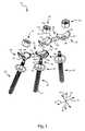
- FIG. 1is an exploded, perspective view of a spinal fusion system according to one embodiment of the invention.
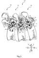
- FIG. 2is a perspective view of the spinal fusion system of FIG. 1 in fully-assembled form, secured to three vertebrae of a spine.
- FIG. 3is a side elevation, section view of the spinal fusion system and the vertebrae of FIG. 2 .
- FIG. 4is a perspective view of a segment of a spinal fusion system according to one alternative embodiment of the invention.
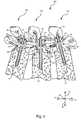
- FIG. 5is an exploded, perspective view of a spinal fusion system according to another alternative embodiment of the invention.
- FIG. 6is a side elevation, section view of a patient's lumbar region, with cannulae and the pedicle screws of the spinal fusion system of FIG. 5 .
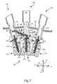
- FIG. 7is a side elevation, section view of the lumbar region and cannulae, with the pedicle screws and the first segment of the spinal fusion system of FIG. 5 .
- FIG. 8is a side elevation, section view of the lumbar region and cannulae, with the pedicle screws and the inferior segment of the spinal fusion system of FIG. 5 , and an additional segment similar to the inferior segment.
- FIG. 9is a side elevation, section view of the lumber region and cannulae, with the entire spinal fusion system of FIG. 5 in place on the vertebrae of the lumbar region, except that the superior segment of FIG. 5 has been replaced by the additional segment.
- the present inventionrelates to spinal fusion systems and methods that are modular and/or percutaneously implantable.
- the drawings and accompanying descriptionare merely exemplary. Accordingly, the scope of the present invention is not intended to be limited by the examples discussed herein, but only by the appended claims.
- FIG. 1an exploded, perspective view illustrates a spinal fusion system 10 according to one embodiment of the invention.
- the spinal fusion system 10or system 10 , may be used for patients with chronic spinal problems including damaged intervertebral discs, spinal stenosis, facet degeneration, and spondylolisthesis.
- Arrows in FIG. 1indicate the orientation of the system 10 upon implantation on the spine, with reference to conventional anatomical directions. More precisely, the arrows illustrate a cephalad direction 12 , a caudal direction 14 , an anterior direction 16 , a posterior direction 18 , and a medial/lateral axis 20 .
- the system 10includes a first fixation member 24 , a second fixation member 26 , a third fixation member 28 , a superior securement section 30 , an inferior securement section 32 , a first nut 34 , a second nut 36 , and a third nut 38 .
- each of the fixation members 24 , 26 , 28may take the form of a pedicle screw.
- the fixation members 24 , 26 , 28will hereinafter be termed first, second, and third pedicle screws 24 , 26 , and 28 .
- the first and second securement sections 32 , 34may be termed first and second segments 32 , 34 .
- Each of the pedicle screws 24 , 26 , 28may have a proximal end 42 , a distal end 44 , and a receiving flange 46 positioned between the proximal end 42 and the distal end 44 .
- Each proximal end 42may have a torque receiver 48 and a threaded portion 50 .
- the torque receivers 48are designed to be engaged by a distal end of a tool (not shown) so that torque can be transmitted from the tool to the pedicle screws 24 , 26 , 28 to drive the pedicle screws 24 , 26 , 28 into bone.
- the threaded portions 50are designed to receive the nuts 34 , 36 , 38 so that the nuts 34 , 36 , 38 can secure the segments 30 , 32 to the pedicle screws 24 , 26 28 in a manner that will be shown and described subsequently.
- the distal ends 44are threaded so that the distal ends 44 can be threadably implanted in bone.
- the pedicle screws 24 , 26 , 28may optionally be cannulated to facilitate guidance of the pedicle screws 24 , 26 , 28 into engagement with the vertebral pedicles via guide wires or other implements (not shown).
- the receiving flanges 46protrude radially from the main bodies of the pedicle screws 24 , 26 , 28 to provide receiving surfaces 52 capable of attachment to the segments 30 , 32 at multiple relative orientations.
- the receiving surfaces 52may be semispherical, and in the embodiment of FIG. 1 , the receiving surfaces 52 are also concave.
- the cephalad segment 30may have a cephalad mounting portion 56 , a caudal mounting portion 58 , and a stem 60 .
- the cephalad mounting portion 56is attachable to the second pedicle screw 26 and the caudal mounting portion 58 is attachable to the first pedicle screw 24 .
- the stem 60connects the cephalad mounting portion 56 to the caudal mounting portion 58 .
- the stem 60may optionally be deformable to permit adjustment of the relative positions and/or orientations of the mounting portions 56 , 58 . However, since the mounting portions 56 , 58 are polyaxially adjustably attachable to the fixation members 24 , 26 , deformation of the stem 60 may not be needed.
- the cephalad mounting portion 56has a concave engagement surface 62 and a convex engagement surface 64 .
- Each of the engagement surfaces 62 , 64has a semispherical shape capable of polyaxially adjustable engagement with a corresponding semispherical shape. More precisely, the concave engagement surface 62 may engage a convex surface with a similar radius of curvature at any of a plurality of relative orientations about three orthogonal axes. Similarly, the convex engagement surface 64 may engage a concave surface with a similar radius of curvature at any of a plurality of relative orientations about three orthogonal axes. If desired, the engagement surfaces 62 , 64 may have substantially the same radius of curvature so that the cephalad mounting portion 56 is able to polyaxially adjustably engage a mounting portion similar to itself from either side.
- the cephalad mounting portion 56also has a passageway 66 capable of receiving the proximal end 42 of the second pedicle screw 26 .
- the passageway 66takes the form of a slot with a rounded interior end.
- the passageway 66intersects the lateral edge of the cephalad mounting portion 56 so that the proximal end 42 can be inserted into the passageway 66 not only via relative anterior/posterior motion between the proximal end 42 and the passageway 66 , but alternatively, via relative medial/lateral motion between the proximal end 42 and the passageway 66 .
- the caudal mounting portion 58has a configuration somewhat similar to that of the cephalad mounting portion 56 . More precisely, the caudal mounting portion 58 has a concave engagement surface 72 and a convex engagement surface 74 . The engagement surfaces 72 , 74 are semispherical and may optionally have the same radius of curvature.
- the caudal mounting portion 58also has a passageway 76 capable of receiving the proximal end 42 of the first pedicle screw 24 . However, unlike the passageway 66 of the cephalad mounting portion 56 , the passageway 76 does not intersect the lateral edge of the caudal mounting portion 58 . Rather, the passageway 76 is fully bounded. Thus, the proximal end 42 must be inserted into the passageway 76 via relative anterior/posterior motion between the proximal end 42 and the passageway 76 .
- the caudal segment 32may be configured in a manner somewhat similar to that of the cephalad segment 30 , and may be designed to operate in a similar manner. As shown, the caudal segment 32 also has a cephalad mounting portion 86 , a caudal mounting portion 88 , and a stem 90 that connects the mounting portions 86 , 88 together.
- the cephalad mounting portion 86has a concave engagement surface 92 , a convex engagement surface 94 , and a passageway 96 .
- the engagement surfaces 92 , 94may be substantially semispherical, and may have the same radius of curvature.
- the cephalad mounting portion 86has a passageway 96 therethrough, which is capable of receiving the proximal end 42 of the first pedicle screw 24 .
- the passageway 96takes the form of a slot that intersects the cephalad edge of the cephalad mounting portion 86 .
- the proximal end 42can be inserted into the passageway 96 not only via relative anterior/posterior motion between the proximal end 42 and the passageway 96 , but alternatively, via relative cephalad/caudal motion between the proximal end 42 and the passageway 96 .
- the caudal mounting portion 88may be substantially identical to the caudal mounting portion 86 .
- the caudal mounting portion 88may thus have a concave engagement surface 102 , a convex engagement surface 104 , and a passageway 106 , which are all substantially the same as their counterparts 92 , 94 , 96 of the cephalad mounting portion 86 .
- the proximal end 42 of the third pedicle screw 28can be inserted into the passageway 106 not only via relative anterior/posterior motion between the proximal end 42 and the passageway 106 , but alternatively, via relative cephalad/caudal motion between the proximal end 42 and the passageway 106 .
- each of the nuts 34 , 36 , 38has a threaded bore 110 , a polygonal perimeter 112 , and a convex compression surface 114 .
- the threaded bores 110are designed to engage the threaded portions 50 of the proximal ends 42 .
- the polygonal perimeters 112are shaped to be engaged by a distal end of a tool (not shown) so that the tool can be used to rotate the threaded bores 110 into engagement with the threaded portions 50 .
- the polygonal perimeters 112may be hexagonal.
- the convex compression surfaces 114may be substantially semispherical in shape, and may have a radius of curvature similar to those of the concave engagement surfaces 62 , 72 , 92 , 102 of the segments 30 , 32 .
- the system 10may be assembled in multiple different configurations. As shown in FIG. 1 , in one exemplary mode of assembly, the inferior segment 32 is first positioned such that the convex engagement surfaces 94 , 104 engage the receiving surfaces 52 of the receiving flanges 46 of the first and third pedicle screws 24 , 28 . Then, the superior segment 30 is positioned such that the convex engagement surface 74 engages the concave engagement surface 92 of the cephalad mounting portion 86 of the inferior segment 32 , and the convex engagement surface 64 engages the receiving surface 52 of the receiving flange 46 of the second pedicle screw 26 .
- the semispherical shapes of the engagement surfaces 62 , 64 , 72 , 74 , 92 , 94 , 102 , 104 and receiving surfaces 52enables the orientations of the segments 30 , 32 to be polyaxially adjusted relative to each other and to the pedicle screws 24 , 26 , 28 .
- This polyaxial adjustabilityis possible about any of three orthogonal axes for each engaging pair of semispherical surfaces.
- the configuration of the system 10can be adjusted to suit a wide variety of spinal morphologies without requiring deformation of any of the components 24 , 26 , 28 , 30 , 32 , 34 , 36 , 38 of the system.
- the phrase “polyaxially adjustability”refers to the ability of one member to be rotated relative to a second member in at least two orthogonal axes, and then attached to the second member in the selected relative orientation.
- the nuts 34 , 36 , 38are rotated into engagement with the threaded portions 50 and tightened to secure the segments, 30 , 32 to the pedicle screws 24 , 26 , 28 . More precisely, the nuts 34 , 36 , 38 press the convex engagement surfaces 94 , 64 , 104 against the receiving surfaces 52 of the first, second, and third pedicle screws 24 , 26 , 28 , respectively, and press the convex engagement surface 74 against the concave engagement surface 92 . Thus, further adjustment of the orientations of the segments 30 , 32 is prevented, and the system 10 is made substantially rigid to prevent relative motion between the associated vertebrae.
- FIG. 2a perspective view illustrates the spinal fusion system 10 of FIG. 1 in fully-assembled form, secured to a portion of a spine 120 .
- the spine 120has a first vertebra 122 , a second vertebra 124 superior to the first vertebra 122 , and a third vertebra 126 inferior to the first vertebra 122 .
- the first vertebra 122has a right pedicle 132
- second vertebra 124has a right pedicle 134
- the third vertebra 126has a right pedicle 136 .
- the pedicle screws 24 , 26 , 28may first be implanted in the pedicles 132 , 134 , 136 , respectively, through the use of methods known in the art.
- guide wires(not shown) may first be implanted in the pedicles 132 , 134 , 136 .
- the pedicles 132 , 134 , 136may be reamed or otherwise resected to remove interfering bone.
- the cannulated pedicle screws 24 , 26 , 28may be inserted over the guide wires to facilitate implantation of the pedicle screws 24 , 26 , 28 into the pedicles 132 , 134 , 136 .
- the segments 30 , 32are placed and adjusted as described previously. Then, the nuts 34 , 36 , 38 are tightened on the proximal ends 42 to secure the segments 30 , 32 , as also described above.
- FIG. 2illustrates usage of the system 10 to provide only unilateral fixation.
- a similar systemmay be also attached to the left pedicles (not visible) of the vertebrae 122 , 124 , 126 to provide bilateral fixation.
- FIG. 3a side elevation, section view illustrates the system 10 secured to the vertebrae 122 , 124 , 126 of FIG. 2 .
- FIG. 3shows the distal ends 44 of the pedicle screws 24 , 26 , 28 , which are implanted in the pedicles 132 , 134 , 136 of the vertebrae 122 , 124 , 126 .
- FIG. 3also illustrates the manner in which the engagement surfaces 62 , 64 , 72 , 74 , 92 , 94 , 102 , 104 , the receiving surfaces 52 , and the convex compression surfaces 114 engage each other.
- the nuts 34 , 36 , 38have been tightened so that the system 10 is substantially rigid, and the vertebrae 122 , 124 , 126 are unable to move relative to each other.
- a perspective viewillustrates a segment 150 of a spinal fusion system (not shown) according to one alternative embodiment of the invention.
- the segment 150has a shape similar to that of the superior segment 30 of the system 10 of FIG. 1 . Accordingly, the segment 150 has a cephalad mounting portion 156 , a caudal mounting portion 158 , and a stem 160 that connects the mounting portions 156 , 158 together.
- the cephalad mounting portion 156has a concave engagement surface 162 and a convex engagement surface 164 , which may be substantially semispherical, and may have the same radius of curvature.
- the cephalad mounting portion 156has a passageway 166 like the corresponding passageway 66 of the superior segment 30 of FIG. 1 . Accordingly, the passageway 166 intersects a lateral edge of the cephalad mounting portion 156 .
- the concave engagement surface 162differs from that of the superior segment 30 of FIG. 1 in that a plurality of surface irregularities 168 are present on the concave engagement surface 162 .
- the surface irregularities 168may take the form of bumps as shown, or may instead be divots, ridges, grooves, peaks, or any other features capable of enhancing frictional force between the concave engagement surface 162 and the surface it engages. If desired, features like the surface irregularities 168 , or differently shaped features, may be present on the convex engagement surface 164 to enhance frictional engagement of the convex engagement surface 164 .
- the caudal mounting portion 158has a concave engagement surface 172 and a convex engagement surface 174 , which may be substantially semispherical, and may have the same radius of curvature.
- the caudal mounting portion 158has a passageway 176 like the corresponding passageway 76 of the superior segment 30 of FIG. 1 . Accordingly, the passageway 176 is fully bounded, and does not intersect any edge of the caudal mounting portion 158 .
- the concave engagement surface 172differs from that of the superior segment 30 of FIG. 1 in that a plurality of surface irregularities 178 are present on the concave engagement surface 172 .
- the surface irregularities 178may take the form of bumps as shown, or may instead be divots, ridges, grooves, peaks, or any other features capable of enhancing frictional force between the concave engagement surface 172 and the surface it engages. If desired, features like the surface irregularities 178 , or differently shaped features, may be present on the convex engagement surface 174 to enhance frictional engagement of the convex engagement surface 174 .
- the surface irregularities 168 and/or the surface irregularities 178may provide a pattern of radial or otherwise evenly-spaced ridges, grooves, and/or other features that provide a clocking feature.
- Such a clocking featuremay limit engagement of the corresponding engagement surfaces 162 , 164 , 172 , 174 with their opposing surfaces to a plurality of discrete relative positions and/or orientations.
- the surface irregularities 168 , 178may help to provide more secure engagement between the segment 150 and any other pedicle screws, nuts, and/or segments to which it is secured.
- the segment 150may help resist slippage of the corresponding system after the system has been locked into the desired configuration.
- FIG. 5an exploded, perspective view illustrates a spinal fusion system 210 according to another alternative embodiment of the invention.
- the system 210includes a first pedicle screw 224 , a second pedicle screw 226 , a third pedicle screw 228 , a superior segment 30 , an inferior segment 32 , a first nut 234 , a second nut 236 , and a third nut 238 .
- the segments 30 , 32may be identical to those of FIG. 1 .
- the system 210is similar to the system 10 , except that in the system 210 , the segments 30 , 32 are oriented such that the concave engagement surfaces 62 , 64 , 72 , 74 , 92 , 94 , 102 , 104 are oriented toward the pedicle screws 224 , 226 , 228 .
- each of the pedicle screws 224 , 226 , 228has a proximal end 242 , a distal end 244 , and a receiving flange 246 between the proximal and distal ends 242 , 244 .
- each of the proximal ends 242has a torque receiver 48 and a threaded portion 50 .
- the torque receivers 48receive torque from a tool to facilitate implantation of the pedicle screws 224 , 226 , 228 , and the threaded portions 50 threadably receive the nuts 234 , 236 , 238 .
- Each of the receiving flanges 246has a receiving surface 252 with a substantially semispherical shape. However, unlike the receiving surfaces 52 , the receiving surfaces 252 are convex. Therefore, the receiving surfaces 52 are shaped to engage the concave engagement surfaces 62 , 72 , 92 , 102 of the segments 30 , 32 .
- each of the nuts 234 , 236 , 238has a threaded bore 310 and a polygonal perimeter 312 .
- each of the nuts 234 , 236 , 238has a concave compression surface 314 .
- the concave compression surfaces 314are shaped to engage the convex engagement surfaces 64 , 74 , 94 , 104 of the segments 30 , 32 .
- the system 210may be assembled in multiple different configurations.
- the superior segment 30may first be positioned such that the concave engagement surfaces 62 , 72 engage the receiving surfaces 252 of the receiving flanges 246 of the first and second pedicle screws 224 , 226 .
- the inferior segment 32is positioned such that the concave engagement surface 92 engages the convex engagement surface 74 of the caudal mounting portion 58 of the superior segment 30 , and the concave engagement surface 102 engages the receiving surface 252 of the receiving flange 246 of the third pedicle screw 228 .
- the superior segment 30may first be positioned such that the concave engagement surfaces 62 , 72 engage the receiving surfaces 252 of the receiving flanges 246 of the first and second pedicle screws 224 , 226 .
- the inferior segment 32is positioned such that the concave engagement surface 92 engages the convex engagement surface 74 of the caudal mounting portion 58 of the superior segment 30 , and the
- the semispherical shapes of the engagement surfaces 62 , 64 , 72 , 74 , 92 , 94 , 102 , 104 and receiving surfaces 252enables the orientations of the segments 30 , 32 to be polyaxially adjusted relative to each other and to the pedicle screws 224 , 226 , 228 .
- the nuts 234 , 236 , 238are rotated into engagement with the threaded portions 50 and tightened to secure the segments, 30 , 32 to the pedicle screws 224 , 226 , 228 .
- the nuts 234 , 236 , 238then press the concave engagement surfaces 72 , 62 , 102 against the receiving surfaces 252 of the first, second, and third pedicle screws 224 , 226 , 228 , respectively, and press the concave engagement surface 92 against the convex engagement surface 74 .
- the system 210is made substantially rigid to prevent relative motion between the associated vertebrae.
- Either of the systems 10 , 210may be implanted in an open access surgical procedure. However, it may be desirable to use minimally-invasive surgical (MIS) techniques to reduce the disruption to surrounding tissues. Accordingly, it may be advantageous to implant one or more components of the systems 10 , 210 percutaneously.
- MISminimally-invasive surgical
- “Percutaneous implantation”refers to motion of an implant to an implantation site within the body, in which at least some of the tissues covering the implantation site remain intact.
- FIGS. 6 through 9illustrate one exemplary procedure for implanting a system similar to the system 210 percutaneously.
- a side elevation, section viewillustrates a patient's lumbar region.
- the patienthas skin 320 , in which a first incision 322 , a second incision 324 , and a third incision 326 have been formed.
- the incisions 322 , 324 , 326are appropriately sized to receive a first cannula 328 , a second cannula 330 , and a third cannula 332 , respectively.
- Each of the cannulae 328 , 330 , 332has a bore 334 extending along its length, a cephalad slot 336 , and a caudal slot 338 .
- the slots 336 , 338extend proximally from the distal ends of the cannulae 328 , 330 , 332 .
- any type of cannula known in the art, and more particularly used for MIS surgery,maybe used.
- guide wiresmay be inserted through the skin at the sites where the incisions 322 , 324 , 326 are to be formed, and implanted into the pedicles 132 , 134 , 136 of the vertebrae 122 , 124 , 126 , respectively.
- Dilators or other devicesmay be used to widen the guide wire entry points to form the incisions 322 , 324 , 326 .
- the distal ends of the cannulae 328 , 330 , 332may then be inserted over the protruding proximal ends of the guide wires and through the incisions 322 , 324 , 326 to maintain access to the pedicles 132 , 134 , 136 .
- the pedicle screws 224 , 226 , 228 of the system 210 of FIG. 5may be implanted in the pedicles 132 , 134 , 136 . More precisely, the first pedicle screw 224 may be inserted over the corresponding guide wire and through the first cannula 328 until the distal end 244 of the first pedicle screw 224 rests on the pedicle 132 of the first vertebra 122 . The first pedicle screw 224 may then be rotated and urged toward the pedicle 132 through the use of a tool (not shown) until the first pedicle screw 224 has been implanted to the proper depth.
- the second and third pedicle screws 226 , 228may be implanted in the pedicles 134 , 136 of the second and third vertebrae 124 , 126 through the second and third cannulae 330 , 332 , respectively, through the use of similar procedures.
- a side elevation, section viewillustrates the lumbar region, cannulae 328 , 330 , 332 , and pedicle screws 224 , 226 , 228 .
- the inferior segment 32may be inserted through the third cannula 332 , with the cephalad mounting portion 86 leading.
- the inferior segment 32may be rotated such that the cephalad mounting portion 86 passes through the cephalad slot 336 of the third cannula 332 , and into the first cannula 328 through the caudal slot 338 of the first cannula 328 .
- This rotationmay be accomplished through the use of a variety of implements (not shown), such as ramp formed in or inserted into the third cannula 332 to direct the cephalad mounting portion 86 toward the first cannula 328 , or a rigid or articulating gripping tool that enables the surgeon to control the orientation of the inferior segment 32 .
- the proximal end 42 of the first pedicle screw 224is able to slide into the passageway 96 as the passageway 96 moves along the cephalad direction relative to the proximal end 42 .
- the edge of the cephalad mounting portion 86then slides along the receiving surface 252 of the first pedicle screw 224 .
- the caudal mounting portion 88may then be dropped onto the third pedicle screw 228 such that the proximal end 42 of the third pedicle screw 228 enters the passageway 106 of the caudal mounting portion 88 .
- a side elevation, section viewillustrates the lumbar region and cannulae 328 , 330 , 332 , with the pedicle screws 224 , 226 , 228 and the inferior segment 32 in place.
- an additional segment substantially identical to the inferior segment 32may be inserted through the first cannula 328 , with the cephalad mounting portion 86 leading.
- the segment 32may then be positioned on the first and second pedicle screws 224 , 226 in substantially the same manner as the inferior segment 32 that has already been implanted to rest on the first and third pedicle screws 224 , 228 .
- the inferior segment 32may be rotated such that the cephalad mounting portion 86 passes through the cephalad slot 336 of the first cannula 328 , and into the second cannula 330 through the caudal slot 338 of the second cannula 330 .
- the proximal end 42 of the second pedicle screw 226is able to slide into the passageway 96 of the cephalad mounting portion 86 as the passageway 96 moves along the cephalad direction relative to the proximal end 42 .
- the edge of the cephalad mounting portion 86then slides along the receiving surface 252 of the second pedicle screw 226 .
- the caudal mounting portion 88may then be dropped onto the cephalad mounting portion 86 of the previously implanted inferior segment 32 such that the proximal end 42 of the first pedicle screw 224 enters the passageway 106 of the caudal mounting portion 88 .
- a side elevation, section viewillustrates the lumber region and cannulae 328 , 330 , 332 , with the entire spinal fusion system in place.
- the first nut 234may be inserted through the first cannula 328 such that the threaded bore 310 of the first nut 234 receives the threaded portion 50 of the proximal end 42 of the first pedicle screw 224 .
- the first nut 234is then tightened.
- the second and third nuts 236 , 238are inserted through the second and third cannulae 330 , 332 and tightened on the threaded portions 50 of the proximal ends 42 of the second and third pedicle screws 226 , 228 .
- the fixation systemis substantially rigid, and further adjustment between any of the receiving surfaces 252 and the engagement surfaces 92 , 94 , 102 , 104 is substantially prevented.
- FIGS. 6 through 9illustrate only one of many potential MIS procedures. Such procedures maybe used with a wide variety of embodiments, including the systems 10 , 210 of FIGS. 1 and 5 and the segment 150 of FIG. 4 .
Landscapes
- Health & Medical Sciences (AREA)
- Orthopedic Medicine & Surgery (AREA)
- Neurology (AREA)
- Life Sciences & Earth Sciences (AREA)
- Surgery (AREA)
- Heart & Thoracic Surgery (AREA)
- Engineering & Computer Science (AREA)
- Biomedical Technology (AREA)
- Nuclear Medicine, Radiotherapy & Molecular Imaging (AREA)
- Medical Informatics (AREA)
- Molecular Biology (AREA)
- Animal Behavior & Ethology (AREA)
- General Health & Medical Sciences (AREA)
- Public Health (AREA)
- Veterinary Medicine (AREA)
- Surgical Instruments (AREA)
Abstract
Description
Claims (7)
Priority Applications (3)
| Application Number | Priority Date | Filing Date | Title |
|---|---|---|---|
| US11/464,161US7766943B1 (en) | 2005-08-11 | 2006-08-11 | Modular percutaneous spinal fusion system and method |
| US12/818,827US8425565B2 (en) | 2005-08-11 | 2010-06-18 | Modular percutaneous spinal fusion |
| US13/863,643US20140135837A1 (en) | 2005-08-11 | 2013-04-16 | Modular percutaneous spinal fusion |
Applications Claiming Priority (2)
| Application Number | Priority Date | Filing Date | Title |
|---|---|---|---|
| US70800605P | 2005-08-11 | 2005-08-11 | |
| US11/464,161US7766943B1 (en) | 2005-08-11 | 2006-08-11 | Modular percutaneous spinal fusion system and method |
Related Child Applications (1)
| Application Number | Title | Priority Date | Filing Date |
|---|---|---|---|
| US12/818,827DivisionUS8425565B2 (en) | 2005-08-11 | 2010-06-18 | Modular percutaneous spinal fusion |
Publications (1)
| Publication Number | Publication Date |
|---|---|
| US7766943B1true US7766943B1 (en) | 2010-08-03 |
Family
ID=42358772
Family Applications (3)
| Application Number | Title | Priority Date | Filing Date |
|---|---|---|---|
| US11/464,161Expired - Fee RelatedUS7766943B1 (en) | 2005-08-11 | 2006-08-11 | Modular percutaneous spinal fusion system and method |
| US12/818,827Expired - Fee RelatedUS8425565B2 (en) | 2005-08-11 | 2010-06-18 | Modular percutaneous spinal fusion |
| US13/863,643AbandonedUS20140135837A1 (en) | 2005-08-11 | 2013-04-16 | Modular percutaneous spinal fusion |
Family Applications After (2)
| Application Number | Title | Priority Date | Filing Date |
|---|---|---|---|
| US12/818,827Expired - Fee RelatedUS8425565B2 (en) | 2005-08-11 | 2010-06-18 | Modular percutaneous spinal fusion |
| US13/863,643AbandonedUS20140135837A1 (en) | 2005-08-11 | 2013-04-16 | Modular percutaneous spinal fusion |
Country Status (1)
| Country | Link |
|---|---|
| US (3) | US7766943B1 (en) |
Cited By (69)
| Publication number | Priority date | Publication date | Assignee | Title |
|---|---|---|---|---|
| US20080071275A1 (en)* | 2001-03-26 | 2008-03-20 | Nu Vasive, Inc. | Spinal alignment system and related methods |
| US20080103501A1 (en)* | 2006-08-11 | 2008-05-01 | Ralph Christopher R | Angled Washer Polyaxial Connection for Dynamic Spine Prosthesis |
| US20080255619A1 (en)* | 2007-04-10 | 2008-10-16 | Schneiderman Gary A | Posterior spinal fixation with colinear facet screw |
| US20090062859A1 (en)* | 2007-08-31 | 2009-03-05 | Michael Mahoney | Method and system for securing a rod to a bone anchor with a connector |
| US20100076493A1 (en)* | 2004-02-17 | 2010-03-25 | Facet Solutions, Inc. | Facet Joint Replacement Instruments and Methods |
| US8021399B2 (en)* | 2005-07-19 | 2011-09-20 | Stephen Ritland | Rod extension for extending fusion construct |
| US8353932B2 (en) | 2005-09-30 | 2013-01-15 | Jackson Roger P | Polyaxial bone anchor assembly with one-piece closure, pressure insert and plastic elongate member |
| US8377067B2 (en) | 2004-02-27 | 2013-02-19 | Roger P. Jackson | Orthopedic implant rod reduction tool set and method |
| US8394133B2 (en) | 2004-02-27 | 2013-03-12 | Roger P. Jackson | Dynamic fixation assemblies with inner core and outer coil-like member |
| US8444681B2 (en) | 2009-06-15 | 2013-05-21 | Roger P. Jackson | Polyaxial bone anchor with pop-on shank, friction fit retainer and winged insert |
| US8475498B2 (en) | 2007-01-18 | 2013-07-02 | Roger P. Jackson | Dynamic stabilization connecting member with cord connection |
| US8591560B2 (en) | 2005-09-30 | 2013-11-26 | Roger P. Jackson | Dynamic stabilization connecting member with elastic core and outer sleeve |
| US8613760B2 (en) | 2005-09-30 | 2013-12-24 | Roger P. Jackson | Dynamic stabilization connecting member with slitted core and outer sleeve |
| US8814911B2 (en) | 2003-06-18 | 2014-08-26 | Roger P. Jackson | Polyaxial bone screw with cam connection and lock and release insert |
| US8852239B2 (en) | 2013-02-15 | 2014-10-07 | Roger P Jackson | Sagittal angle screw with integral shank and receiver |
| US8870928B2 (en) | 2002-09-06 | 2014-10-28 | Roger P. Jackson | Helical guide and advancement flange with radially loaded lip |
| US8894657B2 (en) | 2004-02-27 | 2014-11-25 | Roger P. Jackson | Tool system for dynamic spinal implants |
| US8911479B2 (en) | 2012-01-10 | 2014-12-16 | Roger P. Jackson | Multi-start closures for open implants |
| US8911478B2 (en) | 2012-11-21 | 2014-12-16 | Roger P. Jackson | Splay control closure for open bone anchor |
| US8926672B2 (en) | 2004-11-10 | 2015-01-06 | Roger P. Jackson | Splay control closure for open bone anchor |
| US8926670B2 (en) | 2003-06-18 | 2015-01-06 | Roger P. Jackson | Polyaxial bone screw assembly |
| US8979904B2 (en) | 2007-05-01 | 2015-03-17 | Roger P Jackson | Connecting member with tensioned cord, low profile rigid sleeve and spacer with torsion control |
| US8998959B2 (en) | 2009-06-15 | 2015-04-07 | Roger P Jackson | Polyaxial bone anchors with pop-on shank, fully constrained friction fit retainer and lock and release insert |
| US8998960B2 (en) | 2004-11-10 | 2015-04-07 | Roger P. Jackson | Polyaxial bone screw with helically wound capture connection |
| US20150116945A1 (en)* | 2012-05-22 | 2015-04-30 | Panasonic Intellectual Property Management Co., Ltd. | Semiconductor device and method for manufacturing same |
| US9050139B2 (en) | 2004-02-27 | 2015-06-09 | Roger P. Jackson | Orthopedic implant rod reduction tool set and method |
| US9144444B2 (en) | 2003-06-18 | 2015-09-29 | Roger P Jackson | Polyaxial bone anchor with helical capture connection, insert and dual locking assembly |
| US9168069B2 (en) | 2009-06-15 | 2015-10-27 | Roger P. Jackson | Polyaxial bone anchor with pop-on shank and winged insert with lower skirt for engaging a friction fit retainer |
| US9211150B2 (en) | 2004-11-23 | 2015-12-15 | Roger P. Jackson | Spinal fixation tool set and method |
| US9216039B2 (en) | 2004-02-27 | 2015-12-22 | Roger P. Jackson | Dynamic spinal stabilization assemblies, tool set and method |
| US9216041B2 (en) | 2009-06-15 | 2015-12-22 | Roger P. Jackson | Spinal connecting members with tensioned cords and rigid sleeves for engaging compression inserts |
| WO2016044845A1 (en)* | 2014-09-19 | 2016-03-24 | In Queue Innovations, Llc | Single level fusion systems and methods of assembly and use |
| US9308027B2 (en) | 2005-05-27 | 2016-04-12 | Roger P Jackson | Polyaxial bone screw with shank articulation pressure insert and method |
| US9439683B2 (en) | 2007-01-26 | 2016-09-13 | Roger P Jackson | Dynamic stabilization member with molded connection |
| US9451993B2 (en) | 2014-01-09 | 2016-09-27 | Roger P. Jackson | Bi-radial pop-on cervical bone anchor |
| US9451989B2 (en) | 2007-01-18 | 2016-09-27 | Roger P Jackson | Dynamic stabilization members with elastic and inelastic sections |
| US9480517B2 (en) | 2009-06-15 | 2016-11-01 | Roger P. Jackson | Polyaxial bone anchor with pop-on shank, shank, friction fit retainer, winged insert and low profile edge lock |
| US9566092B2 (en) | 2013-10-29 | 2017-02-14 | Roger P. Jackson | Cervical bone anchor with collet retainer and outer locking sleeve |
| US9597119B2 (en) | 2014-06-04 | 2017-03-21 | Roger P. Jackson | Polyaxial bone anchor with polymer sleeve |
| US9668771B2 (en) | 2009-06-15 | 2017-06-06 | Roger P Jackson | Soft stabilization assemblies with off-set connector |
| US9717533B2 (en) | 2013-12-12 | 2017-08-01 | Roger P. Jackson | Bone anchor closure pivot-splay control flange form guide and advancement structure |
| CN107510499A (en)* | 2017-10-12 | 2017-12-26 | 河南中医药大学 | Posterior spinal fixation instrument |
| US9907574B2 (en) | 2008-08-01 | 2018-03-06 | Roger P. Jackson | Polyaxial bone anchors with pop-on shank, friction fit fully restrained retainer, insert and tool receiving features |
| US9980753B2 (en) | 2009-06-15 | 2018-05-29 | Roger P Jackson | pivotal anchor with snap-in-place insert having rotation blocking extensions |
| EP3344171A1 (en)* | 2015-08-31 | 2018-07-11 | Bpath | Vertebral implant, method for the placement of such an implant and tool for the placement of the implant |
| US10039578B2 (en) | 2003-12-16 | 2018-08-07 | DePuy Synthes Products, Inc. | Methods and devices for minimally invasive spinal fixation element placement |
| US10039577B2 (en) | 2004-11-23 | 2018-08-07 | Roger P Jackson | Bone anchor receiver with horizontal radiused tool attachment structures and parallel planar outer surfaces |
| US10058354B2 (en) | 2013-01-28 | 2018-08-28 | Roger P. Jackson | Pivotal bone anchor assembly with frictional shank head seating surfaces |
| US10064658B2 (en) | 2014-06-04 | 2018-09-04 | Roger P. Jackson | Polyaxial bone anchor with insert guides |
| US10194951B2 (en) | 2005-05-10 | 2019-02-05 | Roger P. Jackson | Polyaxial bone anchor with compound articulation and pop-on shank |
| US10258382B2 (en) | 2007-01-18 | 2019-04-16 | Roger P. Jackson | Rod-cord dynamic connection assemblies with slidable bone anchor attachment members along the cord |
| US10299839B2 (en) | 2003-12-16 | 2019-05-28 | Medos International Sárl | Percutaneous access devices and bone anchor assemblies |
| US10349983B2 (en) | 2003-05-22 | 2019-07-16 | Alphatec Spine, Inc. | Pivotal bone anchor assembly with biased bushing for pre-lock friction fit |
| US10363070B2 (en) | 2009-06-15 | 2019-07-30 | Roger P. Jackson | Pivotal bone anchor assemblies with pressure inserts and snap on articulating retainers |
| US10383660B2 (en) | 2007-05-01 | 2019-08-20 | Roger P. Jackson | Soft stabilization assemblies with pretensioned cords |
| US10485588B2 (en) | 2004-02-27 | 2019-11-26 | Nuvasive, Inc. | Spinal fixation tool attachment structure |
| US10729469B2 (en) | 2006-01-09 | 2020-08-04 | Roger P. Jackson | Flexible spinal stabilization assembly with spacer having off-axis core member |
| WO2021183338A1 (en)* | 2020-03-11 | 2021-09-16 | Chaim Rogozinski | System and method for the treatment of spinal conditions |
| US11229457B2 (en) | 2009-06-15 | 2022-01-25 | Roger P. Jackson | Pivotal bone anchor assembly with insert tool deployment |
| US20220031365A1 (en)* | 2019-02-22 | 2022-02-03 | Ctl Medical Corporation | Fixation screw & method |
| US11241261B2 (en) | 2005-09-30 | 2022-02-08 | Roger P Jackson | Apparatus and method for soft spinal stabilization using a tensionable cord and releasable end structure |
| US11259845B2 (en) | 2017-03-30 | 2022-03-01 | K2M, Inc. | Bone anchor apparatus and method of use thereof |
| US11298156B2 (en) | 2017-03-30 | 2022-04-12 | K2M, Inc. | Modular screw |
| US11317948B2 (en) | 2014-09-19 | 2022-05-03 | In Queue Innovations, Llc | Fusion systems and methods of assembly and use |
| US11419639B2 (en) | 2017-03-30 | 2022-08-23 | K2M, Inc. | Modular offset screw |
| US11419642B2 (en) | 2003-12-16 | 2022-08-23 | Medos International Sarl | Percutaneous access devices and bone anchor assemblies |
| US12114898B2 (en) | 2020-11-19 | 2024-10-15 | K2M, Inc. | Modular head assembly for spinal fixation |
| US12262921B2 (en) | 2020-06-26 | 2025-04-01 | K2M, Inc. | Modular head assembly |
| US12383311B2 (en) | 2010-05-14 | 2025-08-12 | Roger P. Jackson | Pivotal bone anchor assembly and method for use thereof |
Families Citing this family (5)
| Publication number | Priority date | Publication date | Assignee | Title |
|---|---|---|---|---|
| USD894868S1 (en)* | 2018-12-19 | 2020-09-01 | Bose Corporation | Headphones |
| USD895571S1 (en)* | 2018-12-19 | 2020-09-08 | Bose Corporation | Headphones |
| US11583318B2 (en) | 2018-12-21 | 2023-02-21 | Paradigm Spine, Llc | Modular spine stabilization system and associated instruments |
| US11259940B2 (en) | 2019-06-28 | 2022-03-01 | Mis Spine Ip, Llc | Systems and methods for percutaneous spinal interbody fusion (PSIF) |
| US12059168B2 (en) | 2021-06-16 | 2024-08-13 | Ludwig David Orozco Castillo | Systems and methods for ball probe ultrasonic foraminotomy |
Citations (20)
| Publication number | Priority date | Publication date | Assignee | Title |
|---|---|---|---|---|
| US5180393A (en)* | 1990-09-21 | 1993-01-19 | Polyclinique De Bourgogne & Les Hortensiad | Artificial ligament for the spine |
| US5360431A (en) | 1990-04-26 | 1994-11-01 | Cross Medical Products | Transpedicular screw system and method of use |
| US5387213A (en)* | 1991-02-05 | 1995-02-07 | Safir S.A.R.L. | Osseous surgical implant particularly for an intervertebral stabilizer |
| US5569247A (en)* | 1995-03-27 | 1996-10-29 | Smith & Nephew Richards, Inc. | Enhanced variable angle bone bolt |
| US5591166A (en)* | 1995-03-27 | 1997-01-07 | Smith & Nephew Richards, Inc. | Multi angle bone bolt |
| US6083226A (en)* | 1998-04-22 | 2000-07-04 | Fiz; Daniel | Bone fixation device and transverse linking bridge |
| US6273914B1 (en) | 1995-09-28 | 2001-08-14 | Sparta, Inc. | Spinal implant |
| US6355038B1 (en) | 1998-09-25 | 2002-03-12 | Perumala Corporation | Multi-axis internal spinal fixation |
| US6379354B1 (en)* | 1993-10-08 | 2002-04-30 | Chaim Rogozinski | Spinal implant and method |
| US6610062B2 (en)* | 2000-02-16 | 2003-08-26 | Ebi, L.P. | Method and system for spinal fixation |
| US6626904B1 (en)* | 1999-07-27 | 2003-09-30 | Societe Etudes Et Developpements - Sed | Implantable intervertebral connection device |
| US6626909B2 (en) | 2002-02-27 | 2003-09-30 | Kingsley Richard Chin | Apparatus and method for spine fixation |
| US6669697B1 (en) | 1998-09-25 | 2003-12-30 | Perumala Corporation | Self-retaining bolt for internal spinal stabilizers |
| US20040102778A1 (en)* | 2002-11-19 | 2004-05-27 | Huebner Randall J. | Adjustable bone plates |
| US6802844B2 (en) | 2001-03-26 | 2004-10-12 | Nuvasive, Inc | Spinal alignment apparatus and methods |
| US20050171539A1 (en)* | 2004-01-30 | 2005-08-04 | Braun John T. | Orthopedic distraction implants and techniques |
| US20050234454A1 (en)* | 2003-09-24 | 2005-10-20 | Chin Kingsley R | Multi-axial screw with a spherical landing |
| US20060089645A1 (en)* | 2004-10-26 | 2006-04-27 | Concept Matrix, Llc | Internal fixation system for spine surgery |
| US20060265074A1 (en)* | 2004-10-21 | 2006-11-23 | Manoj Krishna | Posterior spinal arthroplasty-development of a new posteriorly inserted artificial disc, a new anteriorly inserted artifical disc and an artificial facet joint |
| US20070093838A1 (en)* | 2005-09-16 | 2007-04-26 | Ulrich Gmbh & Co. Kg | Ventral bone plate |
- 2006
- 2006-08-11USUS11/464,161patent/US7766943B1/ennot_activeExpired - Fee Related
- 2010
- 2010-06-18USUS12/818,827patent/US8425565B2/ennot_activeExpired - Fee Related
- 2013
- 2013-04-16USUS13/863,643patent/US20140135837A1/ennot_activeAbandoned
Patent Citations (21)
| Publication number | Priority date | Publication date | Assignee | Title |
|---|---|---|---|---|
| US5360431A (en) | 1990-04-26 | 1994-11-01 | Cross Medical Products | Transpedicular screw system and method of use |
| US5474555A (en) | 1990-04-26 | 1995-12-12 | Cross Medical Products | Spinal implant system |
| US5180393A (en)* | 1990-09-21 | 1993-01-19 | Polyclinique De Bourgogne & Les Hortensiad | Artificial ligament for the spine |
| US5387213A (en)* | 1991-02-05 | 1995-02-07 | Safir S.A.R.L. | Osseous surgical implant particularly for an intervertebral stabilizer |
| US6379354B1 (en)* | 1993-10-08 | 2002-04-30 | Chaim Rogozinski | Spinal implant and method |
| US5569247A (en)* | 1995-03-27 | 1996-10-29 | Smith & Nephew Richards, Inc. | Enhanced variable angle bone bolt |
| US5591166A (en)* | 1995-03-27 | 1997-01-07 | Smith & Nephew Richards, Inc. | Multi angle bone bolt |
| US6273914B1 (en) | 1995-09-28 | 2001-08-14 | Sparta, Inc. | Spinal implant |
| US6083226A (en)* | 1998-04-22 | 2000-07-04 | Fiz; Daniel | Bone fixation device and transverse linking bridge |
| US6669697B1 (en) | 1998-09-25 | 2003-12-30 | Perumala Corporation | Self-retaining bolt for internal spinal stabilizers |
| US6355038B1 (en) | 1998-09-25 | 2002-03-12 | Perumala Corporation | Multi-axis internal spinal fixation |
| US6626904B1 (en)* | 1999-07-27 | 2003-09-30 | Societe Etudes Et Developpements - Sed | Implantable intervertebral connection device |
| US6610062B2 (en)* | 2000-02-16 | 2003-08-26 | Ebi, L.P. | Method and system for spinal fixation |
| US6802844B2 (en) | 2001-03-26 | 2004-10-12 | Nuvasive, Inc | Spinal alignment apparatus and methods |
| US6626909B2 (en) | 2002-02-27 | 2003-09-30 | Kingsley Richard Chin | Apparatus and method for spine fixation |
| US20040102778A1 (en)* | 2002-11-19 | 2004-05-27 | Huebner Randall J. | Adjustable bone plates |
| US20050234454A1 (en)* | 2003-09-24 | 2005-10-20 | Chin Kingsley R | Multi-axial screw with a spherical landing |
| US20050171539A1 (en)* | 2004-01-30 | 2005-08-04 | Braun John T. | Orthopedic distraction implants and techniques |
| US20060265074A1 (en)* | 2004-10-21 | 2006-11-23 | Manoj Krishna | Posterior spinal arthroplasty-development of a new posteriorly inserted artificial disc, a new anteriorly inserted artifical disc and an artificial facet joint |
| US20060089645A1 (en)* | 2004-10-26 | 2006-04-27 | Concept Matrix, Llc | Internal fixation system for spine surgery |
| US20070093838A1 (en)* | 2005-09-16 | 2007-04-26 | Ulrich Gmbh & Co. Kg | Ventral bone plate |
Cited By (108)
| Publication number | Priority date | Publication date | Assignee | Title |
|---|---|---|---|---|
| US20080071275A1 (en)* | 2001-03-26 | 2008-03-20 | Nu Vasive, Inc. | Spinal alignment system and related methods |
| US9622790B2 (en) | 2001-09-19 | 2017-04-18 | Warsaw Orthopedic, Inc. | Rod extension for extending fusion construct |
| US8870928B2 (en) | 2002-09-06 | 2014-10-28 | Roger P. Jackson | Helical guide and advancement flange with radially loaded lip |
| US10349983B2 (en) | 2003-05-22 | 2019-07-16 | Alphatec Spine, Inc. | Pivotal bone anchor assembly with biased bushing for pre-lock friction fit |
| US8814911B2 (en) | 2003-06-18 | 2014-08-26 | Roger P. Jackson | Polyaxial bone screw with cam connection and lock and release insert |
| US9144444B2 (en) | 2003-06-18 | 2015-09-29 | Roger P Jackson | Polyaxial bone anchor with helical capture connection, insert and dual locking assembly |
| US8936623B2 (en) | 2003-06-18 | 2015-01-20 | Roger P. Jackson | Polyaxial bone screw assembly |
| US8926670B2 (en) | 2003-06-18 | 2015-01-06 | Roger P. Jackson | Polyaxial bone screw assembly |
| US10299839B2 (en) | 2003-12-16 | 2019-05-28 | Medos International Sárl | Percutaneous access devices and bone anchor assemblies |
| US11419642B2 (en) | 2003-12-16 | 2022-08-23 | Medos International Sarl | Percutaneous access devices and bone anchor assemblies |
| US11426216B2 (en) | 2003-12-16 | 2022-08-30 | DePuy Synthes Products, Inc. | Methods and devices for minimally invasive spinal fixation element placement |
| US10039578B2 (en) | 2003-12-16 | 2018-08-07 | DePuy Synthes Products, Inc. | Methods and devices for minimally invasive spinal fixation element placement |
| US9451990B2 (en)* | 2004-02-17 | 2016-09-27 | Globus Medical, Inc. | Facet joint replacement instruments and methods |
| US20100076493A1 (en)* | 2004-02-17 | 2010-03-25 | Facet Solutions, Inc. | Facet Joint Replacement Instruments and Methods |
| US8900270B2 (en)* | 2004-02-17 | 2014-12-02 | Gmedelaware 2 Llc | Facet joint replacement instruments and methods |
| US11147597B2 (en) | 2004-02-27 | 2021-10-19 | Roger P Jackson | Dynamic spinal stabilization assemblies, tool set and method |
| US9532815B2 (en) | 2004-02-27 | 2017-01-03 | Roger P. Jackson | Spinal fixation tool set and method |
| US9662143B2 (en) | 2004-02-27 | 2017-05-30 | Roger P Jackson | Dynamic fixation assemblies with inner core and outer coil-like member |
| US9662151B2 (en) | 2004-02-27 | 2017-05-30 | Roger P Jackson | Orthopedic implant rod reduction tool set and method |
| US9636151B2 (en) | 2004-02-27 | 2017-05-02 | Roger P Jackson | Orthopedic implant rod reduction tool set and method |
| US9055978B2 (en) | 2004-02-27 | 2015-06-16 | Roger P. Jackson | Orthopedic implant rod reduction tool set and method |
| US8894657B2 (en) | 2004-02-27 | 2014-11-25 | Roger P. Jackson | Tool system for dynamic spinal implants |
| US9918751B2 (en) | 2004-02-27 | 2018-03-20 | Roger P. Jackson | Tool system for dynamic spinal implants |
| US11291480B2 (en) | 2004-02-27 | 2022-04-05 | Nuvasive, Inc. | Spinal fixation tool attachment structure |
| US11648039B2 (en) | 2004-02-27 | 2023-05-16 | Roger P. Jackson | Spinal fixation tool attachment structure |
| US9050139B2 (en) | 2004-02-27 | 2015-06-09 | Roger P. Jackson | Orthopedic implant rod reduction tool set and method |
| US9216039B2 (en) | 2004-02-27 | 2015-12-22 | Roger P. Jackson | Dynamic spinal stabilization assemblies, tool set and method |
| US8394133B2 (en) | 2004-02-27 | 2013-03-12 | Roger P. Jackson | Dynamic fixation assemblies with inner core and outer coil-like member |
| US8377067B2 (en) | 2004-02-27 | 2013-02-19 | Roger P. Jackson | Orthopedic implant rod reduction tool set and method |
| US10485588B2 (en) | 2004-02-27 | 2019-11-26 | Nuvasive, Inc. | Spinal fixation tool attachment structure |
| US8998960B2 (en) | 2004-11-10 | 2015-04-07 | Roger P. Jackson | Polyaxial bone screw with helically wound capture connection |
| US11147591B2 (en) | 2004-11-10 | 2021-10-19 | Roger P Jackson | Pivotal bone anchor receiver assembly with threaded closure |
| US8926672B2 (en) | 2004-11-10 | 2015-01-06 | Roger P. Jackson | Splay control closure for open bone anchor |
| US9743957B2 (en) | 2004-11-10 | 2017-08-29 | Roger P. Jackson | Polyaxial bone screw with shank articulation pressure insert and method |
| US9629669B2 (en) | 2004-11-23 | 2017-04-25 | Roger P. Jackson | Spinal fixation tool set and method |
| US10039577B2 (en) | 2004-11-23 | 2018-08-07 | Roger P Jackson | Bone anchor receiver with horizontal radiused tool attachment structures and parallel planar outer surfaces |
| US9522021B2 (en) | 2004-11-23 | 2016-12-20 | Roger P. Jackson | Polyaxial bone anchor with retainer with notch for mono-axial motion |
| US9211150B2 (en) | 2004-11-23 | 2015-12-15 | Roger P. Jackson | Spinal fixation tool set and method |
| US11389214B2 (en) | 2004-11-23 | 2022-07-19 | Roger P. Jackson | Spinal fixation tool set and method |
| US10194951B2 (en) | 2005-05-10 | 2019-02-05 | Roger P. Jackson | Polyaxial bone anchor with compound articulation and pop-on shank |
| US9308027B2 (en) | 2005-05-27 | 2016-04-12 | Roger P Jackson | Polyaxial bone screw with shank articulation pressure insert and method |
| US8845694B2 (en) | 2005-07-19 | 2014-09-30 | Warsaw Orthopedic, Inc. | Rod extension for extending fusion construct |
| US8021399B2 (en)* | 2005-07-19 | 2011-09-20 | Stephen Ritland | Rod extension for extending fusion construct |
| US11241261B2 (en) | 2005-09-30 | 2022-02-08 | Roger P Jackson | Apparatus and method for soft spinal stabilization using a tensionable cord and releasable end structure |
| US8613760B2 (en) | 2005-09-30 | 2013-12-24 | Roger P. Jackson | Dynamic stabilization connecting member with slitted core and outer sleeve |
| US8353932B2 (en) | 2005-09-30 | 2013-01-15 | Jackson Roger P | Polyaxial bone anchor assembly with one-piece closure, pressure insert and plastic elongate member |
| US8696711B2 (en) | 2005-09-30 | 2014-04-15 | Roger P. Jackson | Polyaxial bone anchor assembly with one-piece closure, pressure insert and plastic elongate member |
| US8591560B2 (en) | 2005-09-30 | 2013-11-26 | Roger P. Jackson | Dynamic stabilization connecting member with elastic core and outer sleeve |
| US10729469B2 (en) | 2006-01-09 | 2020-08-04 | Roger P. Jackson | Flexible spinal stabilization assembly with spacer having off-axis core member |
| US9119679B2 (en)* | 2006-08-11 | 2015-09-01 | Globus Medical, Inc. | Angled washer polyaxial connection for dynamic spine prosthesis |
| US8702755B2 (en)* | 2006-08-11 | 2014-04-22 | Gmedelaware 2 Llc | Angled washer polyaxial connection for dynamic spine prosthesis |
| US20080103501A1 (en)* | 2006-08-11 | 2008-05-01 | Ralph Christopher R | Angled Washer Polyaxial Connection for Dynamic Spine Prosthesis |
| US20140303671A1 (en)* | 2006-08-11 | 2014-10-09 | Gmedelaware 2 Llc | Angled Washer Polyaxial Connection for Dynamic Spine Prosthesis |
| US8475498B2 (en) | 2007-01-18 | 2013-07-02 | Roger P. Jackson | Dynamic stabilization connecting member with cord connection |
| US10258382B2 (en) | 2007-01-18 | 2019-04-16 | Roger P. Jackson | Rod-cord dynamic connection assemblies with slidable bone anchor attachment members along the cord |
| US10470801B2 (en) | 2007-01-18 | 2019-11-12 | Roger P. Jackson | Dynamic spinal stabilization with rod-cord longitudinal connecting members |
| US9451989B2 (en) | 2007-01-18 | 2016-09-27 | Roger P Jackson | Dynamic stabilization members with elastic and inelastic sections |
| US10792074B2 (en) | 2007-01-22 | 2020-10-06 | Roger P. Jackson | Pivotal bone anchor assemly with twist-in-place friction fit insert |
| US9439683B2 (en) | 2007-01-26 | 2016-09-13 | Roger P Jackson | Dynamic stabilization member with molded connection |
| US20080255619A1 (en)* | 2007-04-10 | 2008-10-16 | Schneiderman Gary A | Posterior spinal fixation with colinear facet screw |
| US10383660B2 (en) | 2007-05-01 | 2019-08-20 | Roger P. Jackson | Soft stabilization assemblies with pretensioned cords |
| US8979904B2 (en) | 2007-05-01 | 2015-03-17 | Roger P Jackson | Connecting member with tensioned cord, low profile rigid sleeve and spacer with torsion control |
| US8025682B2 (en)* | 2007-08-31 | 2011-09-27 | Depuy Spine, Inc. | Method and system for securing a rod to a bone anchor with a connector |
| US20090062859A1 (en)* | 2007-08-31 | 2009-03-05 | Michael Mahoney | Method and system for securing a rod to a bone anchor with a connector |
| US9907574B2 (en) | 2008-08-01 | 2018-03-06 | Roger P. Jackson | Polyaxial bone anchors with pop-on shank, friction fit fully restrained retainer, insert and tool receiving features |
| US9668771B2 (en) | 2009-06-15 | 2017-06-06 | Roger P Jackson | Soft stabilization assemblies with off-set connector |
| US9393047B2 (en) | 2009-06-15 | 2016-07-19 | Roger P. Jackson | Polyaxial bone anchor with pop-on shank and friction fit retainer with low profile edge lock |
| US9918745B2 (en) | 2009-06-15 | 2018-03-20 | Roger P. Jackson | Polyaxial bone anchor with pop-on shank and winged insert with friction fit compressive collet |
| US11229457B2 (en) | 2009-06-15 | 2022-01-25 | Roger P. Jackson | Pivotal bone anchor assembly with insert tool deployment |
| US9980753B2 (en) | 2009-06-15 | 2018-05-29 | Roger P Jackson | pivotal anchor with snap-in-place insert having rotation blocking extensions |
| US9168069B2 (en) | 2009-06-15 | 2015-10-27 | Roger P. Jackson | Polyaxial bone anchor with pop-on shank and winged insert with lower skirt for engaging a friction fit retainer |
| US8998959B2 (en) | 2009-06-15 | 2015-04-07 | Roger P Jackson | Polyaxial bone anchors with pop-on shank, fully constrained friction fit retainer and lock and release insert |
| US10363070B2 (en) | 2009-06-15 | 2019-07-30 | Roger P. Jackson | Pivotal bone anchor assemblies with pressure inserts and snap on articulating retainers |
| US9480517B2 (en) | 2009-06-15 | 2016-11-01 | Roger P. Jackson | Polyaxial bone anchor with pop-on shank, shank, friction fit retainer, winged insert and low profile edge lock |
| US9717534B2 (en) | 2009-06-15 | 2017-08-01 | Roger P. Jackson | Polyaxial bone anchor with pop-on shank and friction fit retainer with low profile edge lock |
| US9504496B2 (en) | 2009-06-15 | 2016-11-29 | Roger P. Jackson | Polyaxial bone anchor with pop-on shank, friction fit retainer and winged insert |
| US9216041B2 (en) | 2009-06-15 | 2015-12-22 | Roger P. Jackson | Spinal connecting members with tensioned cords and rigid sleeves for engaging compression inserts |
| US8444681B2 (en) | 2009-06-15 | 2013-05-21 | Roger P. Jackson | Polyaxial bone anchor with pop-on shank, friction fit retainer and winged insert |
| US12383311B2 (en) | 2010-05-14 | 2025-08-12 | Roger P. Jackson | Pivotal bone anchor assembly and method for use thereof |
| US9636146B2 (en) | 2012-01-10 | 2017-05-02 | Roger P. Jackson | Multi-start closures for open implants |
| US8911479B2 (en) | 2012-01-10 | 2014-12-16 | Roger P. Jackson | Multi-start closures for open implants |
| US9572291B2 (en)* | 2012-05-22 | 2017-02-14 | Panasonic Intellectual Property Management Co., Ltd. | Semiconductor device and method for manufacturing same |
| US20150116945A1 (en)* | 2012-05-22 | 2015-04-30 | Panasonic Intellectual Property Management Co., Ltd. | Semiconductor device and method for manufacturing same |
| US8911478B2 (en) | 2012-11-21 | 2014-12-16 | Roger P. Jackson | Splay control closure for open bone anchor |
| US9770265B2 (en) | 2012-11-21 | 2017-09-26 | Roger P. Jackson | Splay control closure for open bone anchor |
| US10058354B2 (en) | 2013-01-28 | 2018-08-28 | Roger P. Jackson | Pivotal bone anchor assembly with frictional shank head seating surfaces |
| US8852239B2 (en) | 2013-02-15 | 2014-10-07 | Roger P Jackson | Sagittal angle screw with integral shank and receiver |
| US9566092B2 (en) | 2013-10-29 | 2017-02-14 | Roger P. Jackson | Cervical bone anchor with collet retainer and outer locking sleeve |
| US9717533B2 (en) | 2013-12-12 | 2017-08-01 | Roger P. Jackson | Bone anchor closure pivot-splay control flange form guide and advancement structure |
| US9451993B2 (en) | 2014-01-09 | 2016-09-27 | Roger P. Jackson | Bi-radial pop-on cervical bone anchor |
| US10064658B2 (en) | 2014-06-04 | 2018-09-04 | Roger P. Jackson | Polyaxial bone anchor with insert guides |
| US9597119B2 (en) | 2014-06-04 | 2017-03-21 | Roger P. Jackson | Polyaxial bone anchor with polymer sleeve |
| US12220155B2 (en) | 2014-09-19 | 2025-02-11 | Spine Forward, Llc | Fusion systems and methods of assembly and use |
| WO2016044845A1 (en)* | 2014-09-19 | 2016-03-24 | In Queue Innovations, Llc | Single level fusion systems and methods of assembly and use |
| US11317948B2 (en) | 2014-09-19 | 2022-05-03 | In Queue Innovations, Llc | Fusion systems and methods of assembly and use |
| US10517644B2 (en) | 2014-09-19 | 2019-12-31 | In Queue Innovations, Llc | Single level fusion systems and methods of assembly and use |
| US10987141B2 (en)* | 2015-08-31 | 2021-04-27 | Bpath | Vertebral implant, method for the placement of such an implant and tool for the placement of the implant |
| EP3344171A1 (en)* | 2015-08-31 | 2018-07-11 | Bpath | Vertebral implant, method for the placement of such an implant and tool for the placement of the implant |
| US20190038323A1 (en)* | 2015-08-31 | 2019-02-07 | Bpath | Vertebral implant, method for the placement of such an implant and tool for the placement of the implant |
| US11419639B2 (en) | 2017-03-30 | 2022-08-23 | K2M, Inc. | Modular offset screw |
| US11298156B2 (en) | 2017-03-30 | 2022-04-12 | K2M, Inc. | Modular screw |
| US11259845B2 (en) | 2017-03-30 | 2022-03-01 | K2M, Inc. | Bone anchor apparatus and method of use thereof |
| CN107510499A (en)* | 2017-10-12 | 2017-12-26 | 河南中医药大学 | Posterior spinal fixation instrument |
| US20220031365A1 (en)* | 2019-02-22 | 2022-02-03 | Ctl Medical Corporation | Fixation screw & method |
| WO2021183338A1 (en)* | 2020-03-11 | 2021-09-16 | Chaim Rogozinski | System and method for the treatment of spinal conditions |
| US11849980B2 (en) | 2020-03-11 | 2023-12-26 | Chaim Rogozinski | System and method for the treatment of spinal conditions |
| US12262921B2 (en) | 2020-06-26 | 2025-04-01 | K2M, Inc. | Modular head assembly |
| US12114898B2 (en) | 2020-11-19 | 2024-10-15 | K2M, Inc. | Modular head assembly for spinal fixation |
Also Published As
| Publication number | Publication date |
|---|---|
| US20100256682A1 (en) | 2010-10-07 |
| US8425565B2 (en) | 2013-04-23 |
| US20140135837A1 (en) | 2014-05-15 |
Similar Documents
| Publication | Publication Date | Title |
|---|---|---|
| US7766943B1 (en) | Modular percutaneous spinal fusion system and method | |
| US9649133B2 (en) | Supplemental fixation screw | |
| AU2007333199B2 (en) | Posterior functionally dynamic stabilization system | |
| US7935134B2 (en) | Systems and methods for stabilization of bone structures | |
| US7727260B2 (en) | Method and apparatus for bone stabilization | |
| US9517089B1 (en) | Bone anchor with offset rod connector | |
| US11426212B2 (en) | Motion control and vertebral fixation device | |
| US20070233090A1 (en) | Aligning cross-connector | |
| US12076050B2 (en) | Single level fusion systems and methods of assembly and use | |
| WO2014106244A9 (en) | Interspinous implants | |
| US9427265B2 (en) | Surgical instrument system and method | |
| EP2814412B1 (en) | Bone fastener | |
| CN113038893A (en) | Spinal implant system and method of use | |
| US9757165B2 (en) | Spinal implant system and method | |
| US10736666B2 (en) | Spinal implant system and methods of use | |
| US20160128734A1 (en) | Threaded Setscrew Crosslink | |
| CN119403504A (en) | Spinal Implants | |
| US10307187B2 (en) | Spinal implant system and method |
Legal Events
| Date | Code | Title | Description |
|---|---|---|---|
| AS | Assignment | Owner name:MEDICINELODGE, INC., UTAH Free format text:ASSIGNMENT OF ASSIGNORS INTEREST;ASSIGNORS:FALLIN, T. WADE;JUSTIN, DANIEL F.;REEL/FRAME:018181/0892 Effective date:20060811 | |
| AS | Assignment | Owner name:SANKATY ADVISORS, LLC, MASSACHUSETTS Free format text:SECURITY AGREEMENT;ASSIGNOR:MEDICINELODGE, INC.;REEL/FRAME:018720/0476 Effective date:20070102 | |
| AS | Assignment | Owner name:PNC BANK, NATIONAL ASSOCIATION, AS AGENT, NEW JERS Free format text:SECURITY AGREEMENT;ASSIGNORS:IMDS CORPORATION;FRONTIER BIOMEDICAL, LLC;REEL/FRAME:028157/0389 Effective date:20120502 Owner name:MEDICINELODGE HOLDINGS CORP., TEXAS Free format text:TERMINATION AND RELEASE OF SECURITY INTEREST;ASSIGNOR:SANKATY ADVISORS, LLC, AS ADMINISTRATIVE AGENT;REEL/FRAME:028157/0648 Effective date:20120502 Owner name:MEDICINELODGE, INC., TEXAS Free format text:TERMINATION AND RELEASE OF SECURITY INTEREST;ASSIGNOR:SANKATY ADVISORS, LLC, AS ADMINISTRATIVE AGENT;REEL/FRAME:028157/0648 Effective date:20120502 | |
| AS | Assignment | Owner name:IMDS CORPORATION, UTAH Free format text:RELEASE BY SECURED PARTY;ASSIGNOR:PNC BANK;REEL/FRAME:031174/0714 Effective date:20130830 Owner name:FRONTIER BIOMEDICAL, LLC, UTAH Free format text:RELEASE BY SECURED PARTY;ASSIGNOR:PNC BANK;REEL/FRAME:031174/0714 Effective date:20130830 | |
| REMI | Maintenance fee reminder mailed | ||
| LAPS | Lapse for failure to pay maintenance fees | ||
| STCH | Information on status: patent discontinuation | Free format text:PATENT EXPIRED DUE TO NONPAYMENT OF MAINTENANCE FEES UNDER 37 CFR 1.362 | |
| FP | Expired due to failure to pay maintenance fee | Effective date:20140803 | |
| AS | Assignment | Owner name:IMDS CORPORATION, TEXAS Free format text:RELEASE BY SECURED PARTY;ASSIGNOR:PNC BANK, NATIONAL ASSOCIATION, AS AGENT;REEL/FRAME:037163/0367 Effective date:20151127 |