US7766935B2 - Modified headpiece for hydraulic coil deployment system - Google Patents
Modified headpiece for hydraulic coil deployment systemDownload PDFInfo
- Publication number
- US7766935B2 US7766935B2US11/560,958US56095806AUS7766935B2US 7766935 B2US7766935 B2US 7766935B2US 56095806 AUS56095806 AUS 56095806AUS 7766935 B2US7766935 B2US 7766935B2
- Authority
- US
- United States
- Prior art keywords
- end portion
- occlusion device
- proximal end
- deployment
- deployment catheter
- Prior art date
- Legal status (The legal status is an assumption and is not a legal conclusion. Google has not performed a legal analysis and makes no representation as to the accuracy of the status listed.)
- Expired - Fee Related, expires
Links
Images


Classifications
- A—HUMAN NECESSITIES
- A61—MEDICAL OR VETERINARY SCIENCE; HYGIENE
- A61B—DIAGNOSIS; SURGERY; IDENTIFICATION
- A61B17/00—Surgical instruments, devices or methods
- A61B17/12—Surgical instruments, devices or methods for ligaturing or otherwise compressing tubular parts of the body, e.g. blood vessels or umbilical cord
- A61B17/12022—Occluding by internal devices, e.g. balloons or releasable wires
- A61B17/12131—Occluding by internal devices, e.g. balloons or releasable wires characterised by the type of occluding device
- A61B17/1214—Coils or wires
- A—HUMAN NECESSITIES
- A61—MEDICAL OR VETERINARY SCIENCE; HYGIENE
- A61B—DIAGNOSIS; SURGERY; IDENTIFICATION
- A61B17/00—Surgical instruments, devices or methods
- A61B17/12—Surgical instruments, devices or methods for ligaturing or otherwise compressing tubular parts of the body, e.g. blood vessels or umbilical cord
- A61B17/12022—Occluding by internal devices, e.g. balloons or releasable wires
- A61B17/12131—Occluding by internal devices, e.g. balloons or releasable wires characterised by the type of occluding device
- A61B17/12181—Occluding by internal devices, e.g. balloons or releasable wires characterised by the type of occluding device formed by fluidized, gelatinous or cellular remodelable materials, e.g. embolic liquids, foams or extracellular matrices
- A61B17/1219—Occluding by internal devices, e.g. balloons or releasable wires characterised by the type of occluding device formed by fluidized, gelatinous or cellular remodelable materials, e.g. embolic liquids, foams or extracellular matrices expandable in contact with liquids
- A—HUMAN NECESSITIES
- A61—MEDICAL OR VETERINARY SCIENCE; HYGIENE
- A61B—DIAGNOSIS; SURGERY; IDENTIFICATION
- A61B17/00—Surgical instruments, devices or methods
- A61B2017/00535—Surgical instruments, devices or methods pneumatically or hydraulically operated
- A61B2017/00539—Surgical instruments, devices or methods pneumatically or hydraulically operated hydraulically
- A—HUMAN NECESSITIES
- A61—MEDICAL OR VETERINARY SCIENCE; HYGIENE
- A61B—DIAGNOSIS; SURGERY; IDENTIFICATION
- A61B17/00—Surgical instruments, devices or methods
- A61B17/12—Surgical instruments, devices or methods for ligaturing or otherwise compressing tubular parts of the body, e.g. blood vessels or umbilical cord
- A61B17/12022—Occluding by internal devices, e.g. balloons or releasable wires
- A61B2017/1205—Introduction devices
- A61B2017/12054—Details concerning the detachment of the occluding device from the introduction device
Definitions
- the present inventionis related to the delivery of embolic occlusion devices.
- occlusion deviceshaving a modified headpiece for use with hydraulic deployment systems and methods for deploying such occlusion devices at a preselected location within a patient, in an accurate and rapid manner.
- the occlusion devices and methodsare particularly well suited for deployment of the occlusion devices at a location of concern within the vasculature, especially intracranially, of a patient.
- catheter delivery systemsfor positioning and deploying therapeutic devices, such as dilation balloons, stents and embolic coils, in the vasculature of the human body has become a standard procedure for treating endovascular diseases. It has been found that such devices are particularly useful in treating areas where traditional operational procedures are impossible or pose a great risk to the patient, for example in the treatment of aneurysms in intracranial blood vessels. Due to the delicate tissue surrounding intracranial blood vessels, especially for example brain tissue, it is very difficult and often risky to perform surgical procedures to treat defects of intracranial blood vessels. Advancements in catheter deployment systems have provided an alternative treatment in such cases. Some of the advantages of catheter delivery systems are that they provide methods for treating blood vessels by an approach that has been found to reduce the risk of trauma to the surrounding tissue, and they also allow for treatment of blood vessels that in the past would have been considered inoperable.
- these proceduresinvolve inserting the distal end of a guiding catheter into the vasculature of a patient and traversing it through the vasculature to a predetermined delivery site.
- a vascular occlusion devicesuch as an embolic coil, is attached to the distal end of a deployment catheter which pushes the occlusion device through the guiding catheter and out of the distal end of the guiding catheter into the delivery site.
- Lulo et al.discloses a hydraulic deployment system that has a deployment catheter having a lumen extending throughout the length of the catheter.
- the catheterhas a distal end portion that is formed from a material which expands outwardly when a liquid is applied within the lumen of the catheter.
- a proximal end portion of an occlusion deviceis disposed in fluid-tight engagement within the lumen of the distal portion of the catheter.
- the proximal end portion of the occlusion deviceis typically a generally cylindrical section that, prior to assembly of the system, has a greater diameter than the distal end portion of the deployment catheter prior to assembly of the system and prior to expansion.
- a frictional engagementis formed by inserting the larger diameter proximal end portion of the occlusion device into the smaller diameter distal end portion of the deployment catheter.
- the objective of this prior systemis to provide frictional engagement to not only form a fluid-tight seal but also to secure the occlusion device to the deployment catheter until the desired deployment of the occlusion device.
- the distal end portion of the deployment catheterexpands outwardly and the proximal end portion of the occlusion device is release, thereby deploying the occlusion device.
- the present inventionembodies occlusion devices for use with hydraulic deployment systems.
- the occlusion devicesinclude a headpiece that can be inserted into a distal end portion of a lumen of a hydraulic deployment system deployment catheter.
- a deformable interference elementwhich has an initial configuration and a deformed configuration, is located at the proximal end portion of the headpiece. In the initial configuration, the interference element engages a section of the distal end portion of the deployment catheter to secure the headpiece within the lumen and to provide a high strength attachment between the occlusion device and the deployment catheter. When sufficient fluid pressure is applied to the interference element, the pressure causes the interference element to transition into the deformed configuration.
- the engagement between the interference element and the distal end portion of the deployment catheterlessens, or the interference element completely disengages from the distal end portion of the deployment catheter, and the headpiece is allowed to be advanced out of the lumen of the deployment catheter.
- the distal end of the deployment catheteris comprised of a substantially rigid sleeve, such as a metal hypotube.
- the proximal end portion of the sleeveincludes a ridge or lip that provides an interference surface.
- An occlusion device having a cylindrical headpieceis inserted into the sleeve.
- the proximal end portion of the headpiecehas an interference element in the form of a radial flare that extends radially from the proximal end portion of the headpiece.
- the radial flarehas a diameter larger than that of the proximal end portion of the sleeve and engages the lip at the proximal end portion of the sleeve to secure the headpiece within the sleeve.
- the headpiececan include a relief area that accommodates the deformation of the deformable interference element.
- the relief areacan comprise a space which allows a portion(s) of the headpiece to flex or bend to aid in the deformation of the interference element.
- fluidis introduced into the lumen of the deployment catheter to apply fluid pressure to the interference element.
- the fluid pressurecauses the radial flare to slightly fold or deform so the flare is allowed to be pushed distally past the lip of the sleeve and the headpiece is allowed to be pushed out of the distal end of the sleeve.
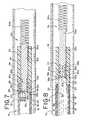
- FIG. 1is an enlarged partially sectioned view of an occlusion device deployment system in accordance with a preferred embodiment of the present invention
- FIG. 2is an enlarged partially sectioned view of the occlusion device deployment system shown in FIG. 1 , during release of the occlusion device;
- FIG. 3is a perspective view of one embodiment of a coupling element in accordance with the present invention, shown prior to deformation of the interference element;
- FIG. 4is a perspective view of the coupling element of FIG. 3 , shown after the interference element has been deformed;
- FIG. 5is a cross-sectional view of the coupling element shown in FIG. 3 , taken along lines 5 - 5 ;
- FIG. 6is a cross-sectional view of the coupling element shown in FIG. 4 , taken along lines 6 - 6 ;
- FIG. 7is an enlarged partially sectioned view of one embodiment of an occlusion device deployment system in combination with another embodiment of the occlusion device;
- FIG. 8is an enlarged partially sectioned view of the occlusion device deployment system shown in FIG. 7 , during release of the occlusion device;
- FIG. 9is a cross-sectional view of another embodiment the coupling element in accordance with the present invention, shown after the coupling element has been deformed.
- FIG. 10is a cross-sectional view of the coupling element of FIG. 9 shown connected to a headpiece having a tubular configuration.
- FIGS. 1 and 2generally illustrate a preferred embodiment of the hydraulic occlusion device deployment system and occlusion device of the present invention.
- the deployment systemgenerally designated at 10 , includes an elongated deployment catheter 12 that can be inserted and advanced through a guide catheter (not shown) to guide an occlusion device 11 to a preselected site within the vascular 14 of a patient in a manner generally known in the art.
- the illustrated deployment catheter 12is comprised of a series of ribbon coils 16 enclosed within a polymer sheath 18 . It will be understood that the deployment catheter can be any type of deployment catheter suitable for deployment of occlusion devices.
- the deployment catheter 12includes a proximal end portion (not shown) and a distal end portion 20 .
- a lumen 22extends along the deployment catheter 12 from the proximal end portion to the distal end portion 20 .
- a hydraulic source(not shown) is operatively connected to the proximal end portion of the deployment catheter 12 to inject fluid into the deployment catheter lumen 22 and to increase fluid pressure within said lumen.
- the hydraulic sourcecan be similar to the hydraulic syringe system disclosed in U.S. Pat. No. 6,544,225 to Lulo, et al., assigned to the same assignee of the present application and incorporated herein by reference.
- the hydraulic sourcecould also be any other suitable hydraulic source known in the art.
- Typical hydraulic fluidis saline solution or other material suitable for internal medical use.
- a coupling sleeve 24is located at the distal end portion 20 of the deployment catheter 12 .
- the coupling sleeve 24has a tubular configuration that includes a lumen 26 (shown in FIG. 2 ) which communicates with lumen 22 .
- the coupling sleeve 24is preferably made of a rigid or semi-rigid material so that the configuration of the coupling sleeve does not substantially change, i.e., expand, upon an increase in fluid pressure within the lumen 26 .
- the coupling sleeveis comprised of a metal hypotube.
- the coupling sleeve 24can be comprised of any other rigid or semi-rigid material that does not change configuration in response to fluid pressure within a catheter, such as a high Durometer polymer.
- the coupling sleeve 24has an indented proximal end portion 28 that is sized to fit into the lumen 22 at the distal end portion 20 of deployment catheter 12 .
- the coupling sleeve 24 and the deployment catheter 12are preferably separate components that are secured together by, for example, adhesive or solder. It is also contemplated that the coupling sleeve 24 and the deployment catheter 12 could be a unitary structure form by, for example, extrusion or molding.
- the occlusion device 11includes an embolic element 30 and a headpiece 32 which are illustrated as separate components that are secured together by adhesive or solder; however, it will be understood that the embolic element 30 and the headpiece 32 can be of a unitary structure which forms the occlusion device.
- the embolic element 30is preferably an embolic coil which can be of the type that takes a substantially linear configuration for being advanced through the guide catheter and a randomly oriented relaxed condition after it has exited from the guide catheter.
- the embolic element 30may be any other type of embolic element which may take on various forms and configurations, such as hydrogels, foams, bioactive coils, braids, cables and hybrid devices.
- the occlusion device headpiece 32has a distal end portion 34 and an indented proximal end portion 36 .
- the distal end portion 34is connected to the embolic element 30
- the proximal end portion 36is sized to fit within the lumen 26 of the coupling sleeve 24 .
- a coupling element 38is located at the proximal end portion 36 of the headpiece 32 .
- the coupling element 38is generally cylindrical and includes a proximal wall 40 and a circumferential sidewall 42 defining a cavity 44 within the coupling element.
- An opening 46is located at the distal end 48 of the coupling element 38 .
- the coupling element 38is attached to the headpiece 32 by placing the coupling element over the indented proximal end portion 36 of the headpiece so that the proximal end portion 36 of the headpiece enters the opening 46 and is located within the cavity 44 of the coupling element, as shown in FIGS. 1 and 2 .
- the coupling element 38 and the headpiece 32are then secured together, for example, by adhesives or solder.
- the proximal end portion 36 of the headpiece 32is indented so that the circumferential sidewall 42 of the coupling element 38 can fit between the headpiece 32 and the coupling sleeve 24 .
- the size of the indent of the proximal end portion 36 of the headpiece 32is substantially equal to the thickness of the circumferential sidewall 42 so that the outer surface of the circumferential wall and outer surface of the headpiece generally align.
- the proximal wall 40 of the coupling element 38includes a deformable interference element 50 .
- the deformable interference element 50is comprised of a radially flared proximal tip 52 of the coupling element.
- the deformable interference element 50includes an initial configuration, as illustrated in FIGS. 3 and 5 , and a slightly deformed or folded configuration, as illustrated in FIGS. 4 and 6 .
- the interference element 50is made from a deformable material that will deform when a hydraulic pressure between about 100 psi and about 1000 psi, typically between about 200 psi and about 900 psi, is applied to the interference element.
- Such materialsinclude flexible metals, metal alloys, such as Nitinol, and deformable polymers.
- the flared proximal tip 52is flared radially and the outer surface 54 of the proximal wall 40 is flat.
- the radial flared proximal tip 52engages an interference surface located on the deployment catheter.
- the radial flared proximal tip 52has a larger diameter then a lip 56 located at the proximal end of the coupling sleeve 24 , and the radial flared proximal tip 52 engages with the lip 56 to provide a high strength attachment between the headpiece 32 and the coupling sleeve 24 , as illustrated and FIG. 1 .
- the interference element 50transitions into a deformed configuration.
- the flared proximal tip 52is slighted folded or deformed inwardly.
- the surface 54 of the proximal wall 40 of the coupling element 38is thereby curved in a concaved dish-like shape, as illustrated in FIGS. 2 , 4 and 6 .
- the deformed configurationallows the flared proximal tip 52 of the coupling member 38 to be advanced distally past the lip 56 of the coupling sleeve 24 , and the headpiece 32 is pushed out to the lumen 26 of coupling sleeve 24 under the force of the hydraulic pressure.
- the headpiece 32 of the occlusion device 11is disposed within the lumen 26 of the coupling sleeve 24 to securely attach the occlusion device 11 to the deployment catheter 12 , as illustrate in FIG. 1 .
- a guide cathetercan be inserted into the vasculature system of a patient, and the distal end portion of the guide catheter can be positioned at a preselected location within a blood vessel, typically in conjunction with other devices and professional procedures as generally known in the art.
- the deployment catheter 12 having an occlusion device 11is inserted into a proximal end portion of the guide catheter, and the deployment catheter 12 is advanced through the guide catheter until the occlusion device 11 reaches the distal end portion of the guide catheter.
- the occlusion device 11may be moved out of the distal end portion of the guide catheter by moving the guide catheter in a retrograde manner, by advancing the deployment catheter 12 , or by a combination of moving the guide catheter in a retrograde manner and advancing the deployment catheter.
- the occlusion device 11can include at least one radiopaque marker, preferably located in the headpiece 32 , so that the position of the occlusion device 11 can be monitored by fluoroscopy. After the occlusion device 11 has exited the guide catheter, if it is determined that the occlusion device is in the wrong position and/or a different occlusion device is required, the deployment catheter 12 can be retracted to move the occlusion device back into the guide catheter. Once in the guide catheter, the occlusion device 11 can be repositioned or completely removed from the patient.
- the hydraulic sourceis activated to inject fluid 58 into the lumen 22 of the deployment catheter 12 and to increase the fluid pressure within the lumen 22 .
- the increased fluid pressureis applied to the coupling element 38 which causes the interference element 50 to deform, e.g., the flared proximal tip 52 slightly folds or deforms inward, as illustrated in FIG. 2 .
- hydraulic pressureadvances the interference element 50 past the lip 56 of the coupling sleeve 24 , and the headpiece 32 is pushed out of the coupling sleeve 24 , thereby deploying the occlusion device.
- FIGS. 7 and 8illustrate the deployment system 10 that is illustrated in combination with an alternative embodiment of the occlusion device, generally designated as 11 a.
- the proximal end portion 36 a of the headpiece 32 a of the occlusion deviceat least partially defines a relief area 37 a ( FIG. 7 ) that allows the proximal wall 40 a of the coupling element 38 a to deform, typically be flexing or bending, which aids in the deformation of the interference element 50 a ( FIGS. 8 and 9 ).
- wall 40 abends in an arcuate manner so that proximal end surface 54 a has a concave-like shape which draws the flared tip 52 a of the interference element 50 a radially inward so that the interference element disengages lip 56 .
- the relief area 37 ais a space that accommodates the deformation of coupling element 38 a by receiving a portion of the coupling element.
- the relief area 37 acan be at least partially defined by the proximal end portion 36 a of the headpiece 32 a .
- the relief area 37 ais defined by a concave proximal end surface 41 a .
- the relief area 37 a defined by the concave surfacereceives a portion of wall 40 a allowing the wall to bend, thereby deforming the flared tip 52 a by drawing the flared tip radially inward.
- the headpiececould have a proximal end portion 36 b that is open ended, such as being of a tubular shape.
- the opening in the lumen 43 b of the tubular proximal end portion 36 b of the headpiecedefines a relief area 37 b.
- the operation of the deployment system of FIGS. 7 and 8is similar to the operation of the deployment system illustrated in FIGS. 1 and 2 .
- the deployment catheter 12is manipulated to guide and position the occlusion device 11 a at a desired delivery site within the body. Once the occlusion device 11 a is at the desire location, the hydraulic source is activated to increase the fluid pressure within lumen 22 . The increased fluid pressure acts upon wall 40 a of coupling element 38 a causing wall 40 a to bend ( FIGS. 8 and 9 ).
Landscapes
- Health & Medical Sciences (AREA)
- Surgery (AREA)
- Life Sciences & Earth Sciences (AREA)
- Heart & Thoracic Surgery (AREA)
- Nuclear Medicine, Radiotherapy & Molecular Imaging (AREA)
- Vascular Medicine (AREA)
- Engineering & Computer Science (AREA)
- Biomedical Technology (AREA)
- Reproductive Health (AREA)
- Medical Informatics (AREA)
- Molecular Biology (AREA)
- Animal Behavior & Ethology (AREA)
- General Health & Medical Sciences (AREA)
- Public Health (AREA)
- Veterinary Medicine (AREA)
- Surgical Instruments (AREA)
Abstract
Description
Claims (17)
Priority Applications (2)
| Application Number | Priority Date | Filing Date | Title |
|---|---|---|---|
| US11/560,958US7766935B2 (en) | 2006-06-12 | 2006-11-17 | Modified headpiece for hydraulic coil deployment system |
| US12/821,863US8920457B2 (en) | 2006-06-12 | 2010-06-23 | Modified headpiece for hydraulic coil deployment system |
Applications Claiming Priority (2)
| Application Number | Priority Date | Filing Date | Title |
|---|---|---|---|
| US11/423,525US7670353B2 (en) | 2006-06-12 | 2006-06-12 | Modified headpiece for hydraulic coil deployment system |
| US11/560,958US7766935B2 (en) | 2006-06-12 | 2006-11-17 | Modified headpiece for hydraulic coil deployment system |
Related Parent Applications (1)
| Application Number | Title | Priority Date | Filing Date |
|---|---|---|---|
| US11/423,525Continuation-In-PartUS7670353B2 (en) | 2006-06-12 | 2006-06-12 | Modified headpiece for hydraulic coil deployment system |
Related Child Applications (1)
| Application Number | Title | Priority Date | Filing Date |
|---|---|---|---|
| US12/821,863DivisionUS8920457B2 (en) | 2006-06-12 | 2010-06-23 | Modified headpiece for hydraulic coil deployment system |
Publications (2)
| Publication Number | Publication Date |
|---|---|
| US20070288050A1 US20070288050A1 (en) | 2007-12-13 |
| US7766935B2true US7766935B2 (en) | 2010-08-03 |
Family
ID=46326637
Family Applications (2)
| Application Number | Title | Priority Date | Filing Date |
|---|---|---|---|
| US11/560,958Expired - Fee RelatedUS7766935B2 (en) | 2006-06-12 | 2006-11-17 | Modified headpiece for hydraulic coil deployment system |
| US12/821,863Expired - Fee RelatedUS8920457B2 (en) | 2006-06-12 | 2010-06-23 | Modified headpiece for hydraulic coil deployment system |
Family Applications After (1)
| Application Number | Title | Priority Date | Filing Date |
|---|---|---|---|
| US12/821,863Expired - Fee RelatedUS8920457B2 (en) | 2006-06-12 | 2010-06-23 | Modified headpiece for hydraulic coil deployment system |
Country Status (1)
| Country | Link |
|---|---|
| US (2) | US7766935B2 (en) |
Cited By (2)
| Publication number | Priority date | Publication date | Assignee | Title |
|---|---|---|---|---|
| US20100262179A1 (en)* | 2006-06-12 | 2010-10-14 | Codman & Shurtleff, Inc. | Modified headpiece for hydraulic coil deployment system |
| US10106884B2 (en)* | 1999-11-19 | 2018-10-23 | Vactronix Scientific, Llc | Compliant implantable medical devices and methods of making same |
Families Citing this family (2)
| Publication number | Priority date | Publication date | Assignee | Title |
|---|---|---|---|---|
| JP6521872B2 (en)* | 2013-03-15 | 2019-05-29 | インプランティカ・パテント・リミテッド | Restraint device |
| US12035919B2 (en)* | 2017-08-10 | 2024-07-16 | Philips Image Guided Therapy Corporation | Real-time monitoring of fluid flow with flow sensing element in an aneurysm and associated devices, systems, and methods |
Citations (67)
| Publication number | Priority date | Publication date | Assignee | Title |
|---|---|---|---|---|
| US4390599A (en) | 1980-07-31 | 1983-06-28 | Raychem Corporation | Enhanced recovery memory metal device |
| US4864824A (en) | 1988-10-31 | 1989-09-12 | American Telephone And Telegraph Company, At&T Bell Laboratories | Thin film shape memory alloy and method for producing |
| US4981756A (en) | 1989-03-21 | 1991-01-01 | Vac-Tec Systems, Inc. | Method for coated surgical instruments and tools |
| US5061914A (en) | 1989-06-27 | 1991-10-29 | Tini Alloy Company | Shape-memory alloy micro-actuator |
| US5082359A (en) | 1989-11-28 | 1992-01-21 | Epion Corporation | Diamond films and method of growing diamond films on nondiamond substrates |
| US5167624A (en) | 1990-11-09 | 1992-12-01 | Catheter Research, Inc. | Embolus delivery system and method |
| US5178957A (en) | 1989-05-02 | 1993-01-12 | Minnesota Mining And Manufacturing Company | Noble metal-polymer composites and flexible thin-film conductors prepared therefrom |
| US5197978A (en) | 1991-04-26 | 1993-03-30 | Advanced Coronary Technology, Inc. | Removable heat-recoverable tissue supporting device |
| US5288230A (en) | 1991-07-18 | 1994-02-22 | Minnesota Mining And Manufacturing Company | Coated orthodontic archwire |
| US5334216A (en) | 1992-12-10 | 1994-08-02 | Howmedica Inc. | Hemostatic plug |
| US5360397A (en) | 1993-07-02 | 1994-11-01 | Corvita Corporation | Hemodiaylsis catheter and catheter assembly |
| US5403700A (en) | 1990-02-14 | 1995-04-04 | Eli Lilly And Company | Method of making a thin film electrical component |
| US5543019A (en) | 1993-04-23 | 1996-08-06 | Etex Corporation | Method of coating medical devices and device coated thereby |
| US5607463A (en) | 1993-03-30 | 1997-03-04 | Medtronic, Inc. | Intravascular medical device |
| US5629077A (en) | 1994-06-27 | 1997-05-13 | Advanced Cardiovascular Systems, Inc. | Biodegradable mesh and film stent |
| US5656036A (en) | 1992-09-01 | 1997-08-12 | Expandable Grafts Partnership | Apparatus for occluding vessels |
| US5669931A (en) | 1995-03-30 | 1997-09-23 | Target Therapeutics, Inc. | Liquid coils with secondary shape |
| US5669977A (en) | 1995-12-22 | 1997-09-23 | Lam Research Corporation | Shape memory alloy lift pins for semiconductor processing equipment |
| US5681575A (en) | 1992-05-19 | 1997-10-28 | Westaim Technologies Inc. | Anti-microbial coating for medical devices |
| US5685961A (en) | 1992-03-27 | 1997-11-11 | P & D Medical Coatings, Inc. | Method for fabrication of metallized medical devices |
| US5735892A (en) | 1993-08-18 | 1998-04-07 | W. L. Gore & Associates, Inc. | Intraluminal stent graft |
| US5744958A (en) | 1995-11-07 | 1998-04-28 | Iti Medical Technologies, Inc. | Instrument having ultra-thin conductive coating and method for magnetic resonance imaging of such instrument |
| US5843289A (en) | 1996-01-22 | 1998-12-01 | Etex Corporation | Surface modification of medical implants |
| US5902317A (en) | 1994-06-01 | 1999-05-11 | Nitinol Medical Technologies, Inc. | Stent and method and apparatus for forming and delivering the same |
| US5908409A (en) | 1997-08-26 | 1999-06-01 | Mcghan Medical Corporation | Tubing plug |
| US5925038A (en) | 1996-01-19 | 1999-07-20 | Ep Technologies, Inc. | Expandable-collapsible electrode structures for capacitive coupling to tissue |
| US5945153A (en) | 1994-07-11 | 1999-08-31 | Southwest Research Institute | Non-irritating antimicrobial coating for medical implants and a process for preparing same |
| US5951586A (en) | 1996-05-15 | 1999-09-14 | Medtronic, Inc. | Intraluminal stent |
| US5976162A (en) | 1996-04-10 | 1999-11-02 | Target Therapeutics, Inc. | Soft-ended fibered micro vaso-occlusive devices |
| US6013084A (en) | 1995-06-30 | 2000-01-11 | Target Therapeutics, Inc. | Stretch resistant vaso-occlusive coils (II) |
| US6017553A (en) | 1992-05-19 | 2000-01-25 | Westaim Technologies, Inc. | Anti-microbial materials |
| US6043451A (en) | 1997-11-06 | 2000-03-28 | Promet Technologies, Inc. | Plasma spraying of nickel-titanium compound |
| US6096175A (en) | 1998-07-17 | 2000-08-01 | Micro Therapeutics, Inc. | Thin film stent |
| US6174329B1 (en) | 1996-08-22 | 2001-01-16 | Advanced Cardiovascular Systems, Inc. | Protective coating for a stent with intermediate radiopaque coating |
| US6203732B1 (en) | 1998-07-02 | 2001-03-20 | Intra Therapeutics, Inc. | Method for manufacturing intraluminal device |
| US6238415B1 (en) | 1994-12-22 | 2001-05-29 | Target Therapeutics, Inc | Implant delivery assembly with expandable coupling/decoupling mechanism |
| US20010020182A1 (en) | 1999-02-26 | 2001-09-06 | Klumb Katherine J. | Expandable coil endoluminal prosthesis |
| US20010039449A1 (en) | 2000-01-24 | 2001-11-08 | A. David Johnson | Thin-film shape memory alloy device and method |
| US6319277B1 (en) | 1994-08-12 | 2001-11-20 | Meadox Medicals, Inc. | Nested stent |
| US6322588B1 (en) | 1999-08-17 | 2001-11-27 | St. Jude Medical, Inc. | Medical devices with metal/polymer composites |
| US6325824B2 (en) | 1998-07-22 | 2001-12-04 | Advanced Cardiovascular Systems, Inc. | Crush resistant stent |
| US6342067B1 (en) | 1998-01-09 | 2002-01-29 | Nitinol Development Corporation | Intravascular stent having curved bridges for connecting adjacent hoops |
| US20020032478A1 (en) | 2000-08-07 | 2002-03-14 | Percardia, Inc. | Myocardial stents and related methods of providing direct blood flow from a heart chamber to a coronary vessel |
| US20020038143A1 (en) | 1995-03-10 | 2002-03-28 | Mccrea Brendan J. | Diametrically adaptable encapsulated stent and methods for deployment thereof |
| US6428557B1 (en) | 1998-12-16 | 2002-08-06 | Arthesys, Sa | Catheter system for release of embolization coils by hydraulic pressure |
| US6432116B1 (en) | 1996-12-18 | 2002-08-13 | Ovion, Inc. | Occluding device and method of use |
| US20020111667A1 (en) | 2000-11-02 | 2002-08-15 | Scimed Life Systems, Inc. | Non-expanded porous polytetrafluoroethylene (PTFE) products and methods of manufacture |
| US6436132B1 (en) | 2000-03-30 | 2002-08-20 | Advanced Cardiovascular Systems, Inc. | Composite intraluminal prostheses |
| US6447478B1 (en) | 1998-05-15 | 2002-09-10 | Ronald S. Maynard | Thin-film shape memory alloy actuators and processing methods |
| US6458119B1 (en) | 1992-11-18 | 2002-10-01 | Target Therapeutics, Inc. | Ultrasoft embolism devices and process for using them |
| US20020151958A1 (en) | 2000-03-03 | 2002-10-17 | Chuter Timothy A.M. | Large vessel stents and occluders |
| US6471721B1 (en) | 1999-12-30 | 2002-10-29 | Advanced Cardiovascular Systems, Inc. | Vascular stent having increased radiopacity and method for making same |
| US20030004567A1 (en) | 2000-11-07 | 2003-01-02 | Boyle Christopher T. | Endoluminal stent, self-supporting endoluminal graft and methods of making same |
| US6537310B1 (en) | 1999-11-19 | 2003-03-25 | Advanced Bio Prosthetic Surfaces, Ltd. | Endoluminal implantable devices and method of making same |
| US6544225B1 (en)* | 2000-02-29 | 2003-04-08 | Cordis Neurovascular, Inc. | Embolic coil hydraulic deployment system with purge mechanism |
| US20030066533A1 (en) | 2001-10-05 | 2003-04-10 | Loy Randall A. | Removable fallopian tube plug and associated methods |
| US6605111B2 (en) | 1998-06-04 | 2003-08-12 | New York University | Endovascular thin film devices and methods for treating and preventing stroke |
| US6627246B2 (en) | 2000-05-16 | 2003-09-30 | Ortho-Mcneil Pharmaceutical, Inc. | Process for coating stents and other medical devices using super-critical carbon dioxide |
| US6645243B2 (en) | 1997-01-09 | 2003-11-11 | Sorin Biomedica Cardio S.P.A. | Stent for angioplasty and a production process therefor |
| US6689141B2 (en)* | 2000-10-18 | 2004-02-10 | Microvention, Inc. | Mechanism for the deployment of endovascular implants |
| US20040034363A1 (en) | 2002-07-23 | 2004-02-19 | Peter Wilson | Stretch resistant therapeutic device |
| US6726993B2 (en) | 1997-12-02 | 2004-04-27 | Teer Coatings Limited | Carbon coatings, method and apparatus for applying them, and articles bearing such coatings |
| US20040098094A1 (en) | 2002-09-26 | 2004-05-20 | Boyle Christopher T. | Implantable graft and methods of making same |
| US20040143288A1 (en) | 2002-08-27 | 2004-07-22 | Gary Searle | Mechanical occluding and dilation device for a vessel |
| US6786920B2 (en) | 1996-07-03 | 2004-09-07 | Edwards Lifesciences Corporation | Radially expandable stented tubular PTFE grafts |
| US6805898B1 (en) | 2000-09-28 | 2004-10-19 | Advanced Cardiovascular Systems, Inc. | Surface features of an implantable medical device |
| US6994711B2 (en) | 1998-03-10 | 2006-02-07 | Cordis Corporation | Small diameter embolic coil hydraulic deployment system |
Family Cites Families (4)
| Publication number | Priority date | Publication date | Assignee | Title |
|---|---|---|---|---|
| US5082356A (en)* | 1990-01-25 | 1992-01-21 | Gte Products Corporation | Temperature control apparatus for controlling metallic vapor pressure in a closed cell |
| US6248102B1 (en) | 1997-04-04 | 2001-06-19 | Keralase Ltd. | Method of hair removal by transcutaneous application of laser light |
| US7766935B2 (en)* | 2006-06-12 | 2010-08-03 | Codman & Shurtleff, Inc. | Modified headpiece for hydraulic coil deployment system |
| US20080111667A1 (en)* | 2006-11-15 | 2008-05-15 | General Electric | System for simplified trailer driver communication and a method of operating the same |
- 2006
- 2006-11-17USUS11/560,958patent/US7766935B2/ennot_activeExpired - Fee Related
- 2010
- 2010-06-23USUS12/821,863patent/US8920457B2/ennot_activeExpired - Fee Related
Patent Citations (78)
| Publication number | Priority date | Publication date | Assignee | Title |
|---|---|---|---|---|
| US4390599A (en) | 1980-07-31 | 1983-06-28 | Raychem Corporation | Enhanced recovery memory metal device |
| US4864824A (en) | 1988-10-31 | 1989-09-12 | American Telephone And Telegraph Company, At&T Bell Laboratories | Thin film shape memory alloy and method for producing |
| US4981756A (en) | 1989-03-21 | 1991-01-01 | Vac-Tec Systems, Inc. | Method for coated surgical instruments and tools |
| US5178957A (en) | 1989-05-02 | 1993-01-12 | Minnesota Mining And Manufacturing Company | Noble metal-polymer composites and flexible thin-film conductors prepared therefrom |
| US5061914A (en) | 1989-06-27 | 1991-10-29 | Tini Alloy Company | Shape-memory alloy micro-actuator |
| US5082359A (en) | 1989-11-28 | 1992-01-21 | Epion Corporation | Diamond films and method of growing diamond films on nondiamond substrates |
| US5403700A (en) | 1990-02-14 | 1995-04-04 | Eli Lilly And Company | Method of making a thin film electrical component |
| US5167624A (en) | 1990-11-09 | 1992-12-01 | Catheter Research, Inc. | Embolus delivery system and method |
| US5197978B1 (en) | 1991-04-26 | 1996-05-28 | Advanced Coronary Tech | Removable heat-recoverable tissue supporting device |
| US5197978A (en) | 1991-04-26 | 1993-03-30 | Advanced Coronary Technology, Inc. | Removable heat-recoverable tissue supporting device |
| US5288230A (en) | 1991-07-18 | 1994-02-22 | Minnesota Mining And Manufacturing Company | Coated orthodontic archwire |
| US5685961A (en) | 1992-03-27 | 1997-11-11 | P & D Medical Coatings, Inc. | Method for fabrication of metallized medical devices |
| US6017553A (en) | 1992-05-19 | 2000-01-25 | Westaim Technologies, Inc. | Anti-microbial materials |
| US5681575A (en) | 1992-05-19 | 1997-10-28 | Westaim Technologies Inc. | Anti-microbial coating for medical devices |
| US6238686B1 (en) | 1992-05-19 | 2001-05-29 | Westaim Technologies | Anti-microbial coating for medical devices |
| US5770255A (en) | 1992-05-19 | 1998-06-23 | Westaim Technologies, Inc. | Anti-microbial coating for medical devices |
| US5753251A (en) | 1992-05-19 | 1998-05-19 | Westaim Technologies, Inc. | Anti-microbial coating for medical device |
| US5656036A (en) | 1992-09-01 | 1997-08-12 | Expandable Grafts Partnership | Apparatus for occluding vessels |
| US6458119B1 (en) | 1992-11-18 | 2002-10-01 | Target Therapeutics, Inc. | Ultrasoft embolism devices and process for using them |
| US5334216A (en) | 1992-12-10 | 1994-08-02 | Howmedica Inc. | Hemostatic plug |
| US5607463A (en) | 1993-03-30 | 1997-03-04 | Medtronic, Inc. | Intravascular medical device |
| US5543019A (en) | 1993-04-23 | 1996-08-06 | Etex Corporation | Method of coating medical devices and device coated thereby |
| US5360397A (en) | 1993-07-02 | 1994-11-01 | Corvita Corporation | Hemodiaylsis catheter and catheter assembly |
| US5810870A (en) | 1993-08-18 | 1998-09-22 | W. L. Gore & Associates, Inc. | Intraluminal stent graft |
| US5735892A (en) | 1993-08-18 | 1998-04-07 | W. L. Gore & Associates, Inc. | Intraluminal stent graft |
| US5925075A (en) | 1993-08-18 | 1999-07-20 | W. L. Gore & Associates, Inc. | Intraluminal stent graft |
| US5902317A (en) | 1994-06-01 | 1999-05-11 | Nitinol Medical Technologies, Inc. | Stent and method and apparatus for forming and delivering the same |
| US5766710A (en) | 1994-06-27 | 1998-06-16 | Advanced Cardiovascular Systems, Inc. | Biodegradable mesh and film stent |
| US5629077A (en) | 1994-06-27 | 1997-05-13 | Advanced Cardiovascular Systems, Inc. | Biodegradable mesh and film stent |
| US5945153A (en) | 1994-07-11 | 1999-08-31 | Southwest Research Institute | Non-irritating antimicrobial coating for medical implants and a process for preparing same |
| US6319277B1 (en) | 1994-08-12 | 2001-11-20 | Meadox Medicals, Inc. | Nested stent |
| US6238415B1 (en) | 1994-12-22 | 2001-05-29 | Target Therapeutics, Inc | Implant delivery assembly with expandable coupling/decoupling mechanism |
| US20020038143A1 (en) | 1995-03-10 | 2002-03-28 | Mccrea Brendan J. | Diametrically adaptable encapsulated stent and methods for deployment thereof |
| US5669931A (en) | 1995-03-30 | 1997-09-23 | Target Therapeutics, Inc. | Liquid coils with secondary shape |
| US6013084A (en) | 1995-06-30 | 2000-01-11 | Target Therapeutics, Inc. | Stretch resistant vaso-occlusive coils (II) |
| US5744958A (en) | 1995-11-07 | 1998-04-28 | Iti Medical Technologies, Inc. | Instrument having ultra-thin conductive coating and method for magnetic resonance imaging of such instrument |
| US5669977A (en) | 1995-12-22 | 1997-09-23 | Lam Research Corporation | Shape memory alloy lift pins for semiconductor processing equipment |
| US5925038A (en) | 1996-01-19 | 1999-07-20 | Ep Technologies, Inc. | Expandable-collapsible electrode structures for capacitive coupling to tissue |
| US5843289A (en) | 1996-01-22 | 1998-12-01 | Etex Corporation | Surface modification of medical implants |
| US5976162A (en) | 1996-04-10 | 1999-11-02 | Target Therapeutics, Inc. | Soft-ended fibered micro vaso-occlusive devices |
| US5951586A (en) | 1996-05-15 | 1999-09-14 | Medtronic, Inc. | Intraluminal stent |
| US6786920B2 (en) | 1996-07-03 | 2004-09-07 | Edwards Lifesciences Corporation | Radially expandable stented tubular PTFE grafts |
| US6174329B1 (en) | 1996-08-22 | 2001-01-16 | Advanced Cardiovascular Systems, Inc. | Protective coating for a stent with intermediate radiopaque coating |
| US6432116B1 (en) | 1996-12-18 | 2002-08-13 | Ovion, Inc. | Occluding device and method of use |
| US6645243B2 (en) | 1997-01-09 | 2003-11-11 | Sorin Biomedica Cardio S.P.A. | Stent for angioplasty and a production process therefor |
| US5908409A (en) | 1997-08-26 | 1999-06-01 | Mcghan Medical Corporation | Tubing plug |
| US6043451A (en) | 1997-11-06 | 2000-03-28 | Promet Technologies, Inc. | Plasma spraying of nickel-titanium compound |
| US6726993B2 (en) | 1997-12-02 | 2004-04-27 | Teer Coatings Limited | Carbon coatings, method and apparatus for applying them, and articles bearing such coatings |
| US6342067B1 (en) | 1998-01-09 | 2002-01-29 | Nitinol Development Corporation | Intravascular stent having curved bridges for connecting adjacent hoops |
| US6994711B2 (en) | 1998-03-10 | 2006-02-07 | Cordis Corporation | Small diameter embolic coil hydraulic deployment system |
| US6447478B1 (en) | 1998-05-15 | 2002-09-10 | Ronald S. Maynard | Thin-film shape memory alloy actuators and processing methods |
| US6605111B2 (en) | 1998-06-04 | 2003-08-12 | New York University | Endovascular thin film devices and methods for treating and preventing stroke |
| US6666882B1 (en) | 1998-06-04 | 2003-12-23 | New York University | Endovascular thin film devices and methods for treating and preventing stroke |
| US6203732B1 (en) | 1998-07-02 | 2001-03-20 | Intra Therapeutics, Inc. | Method for manufacturing intraluminal device |
| US6096175A (en) | 1998-07-17 | 2000-08-01 | Micro Therapeutics, Inc. | Thin film stent |
| US6527919B1 (en) | 1998-07-17 | 2003-03-04 | Micro Therapeutics, Inc. | Thin film stent |
| US6325824B2 (en) | 1998-07-22 | 2001-12-04 | Advanced Cardiovascular Systems, Inc. | Crush resistant stent |
| US6428557B1 (en) | 1998-12-16 | 2002-08-06 | Arthesys, Sa | Catheter system for release of embolization coils by hydraulic pressure |
| US20010020182A1 (en) | 1999-02-26 | 2001-09-06 | Klumb Katherine J. | Expandable coil endoluminal prosthesis |
| US6660032B2 (en) | 1999-02-26 | 2003-12-09 | Vascular Architects, Inc. | Expandable coil endoluminal prosthesis |
| US6322588B1 (en) | 1999-08-17 | 2001-11-27 | St. Jude Medical, Inc. | Medical devices with metal/polymer composites |
| US6537310B1 (en) | 1999-11-19 | 2003-03-25 | Advanced Bio Prosthetic Surfaces, Ltd. | Endoluminal implantable devices and method of making same |
| US6471721B1 (en) | 1999-12-30 | 2002-10-29 | Advanced Cardiovascular Systems, Inc. | Vascular stent having increased radiopacity and method for making same |
| US6533905B2 (en) | 2000-01-24 | 2003-03-18 | Tini Alloy Company | Method for sputtering tini shape-memory alloys |
| US20010039449A1 (en) | 2000-01-24 | 2001-11-08 | A. David Johnson | Thin-film shape memory alloy device and method |
| US6544225B1 (en)* | 2000-02-29 | 2003-04-08 | Cordis Neurovascular, Inc. | Embolic coil hydraulic deployment system with purge mechanism |
| US20020151958A1 (en) | 2000-03-03 | 2002-10-17 | Chuter Timothy A.M. | Large vessel stents and occluders |
| US6436132B1 (en) | 2000-03-30 | 2002-08-20 | Advanced Cardiovascular Systems, Inc. | Composite intraluminal prostheses |
| US6627246B2 (en) | 2000-05-16 | 2003-09-30 | Ortho-Mcneil Pharmaceutical, Inc. | Process for coating stents and other medical devices using super-critical carbon dioxide |
| US20020032478A1 (en) | 2000-08-07 | 2002-03-14 | Percardia, Inc. | Myocardial stents and related methods of providing direct blood flow from a heart chamber to a coronary vessel |
| US6805898B1 (en) | 2000-09-28 | 2004-10-19 | Advanced Cardiovascular Systems, Inc. | Surface features of an implantable medical device |
| US6689141B2 (en)* | 2000-10-18 | 2004-02-10 | Microvention, Inc. | Mechanism for the deployment of endovascular implants |
| US20020111667A1 (en) | 2000-11-02 | 2002-08-15 | Scimed Life Systems, Inc. | Non-expanded porous polytetrafluoroethylene (PTFE) products and methods of manufacture |
| US20030004567A1 (en) | 2000-11-07 | 2003-01-02 | Boyle Christopher T. | Endoluminal stent, self-supporting endoluminal graft and methods of making same |
| US20030066533A1 (en) | 2001-10-05 | 2003-04-10 | Loy Randall A. | Removable fallopian tube plug and associated methods |
| US20040034363A1 (en) | 2002-07-23 | 2004-02-19 | Peter Wilson | Stretch resistant therapeutic device |
| US20040143288A1 (en) | 2002-08-27 | 2004-07-22 | Gary Searle | Mechanical occluding and dilation device for a vessel |
| US20040098094A1 (en) | 2002-09-26 | 2004-05-20 | Boyle Christopher T. | Implantable graft and methods of making same |
Cited By (3)
| Publication number | Priority date | Publication date | Assignee | Title |
|---|---|---|---|---|
| US10106884B2 (en)* | 1999-11-19 | 2018-10-23 | Vactronix Scientific, Llc | Compliant implantable medical devices and methods of making same |
| US20100262179A1 (en)* | 2006-06-12 | 2010-10-14 | Codman & Shurtleff, Inc. | Modified headpiece for hydraulic coil deployment system |
| US8920457B2 (en)* | 2006-06-12 | 2014-12-30 | Depuy Synthes Products Llc | Modified headpiece for hydraulic coil deployment system |
Also Published As
| Publication number | Publication date |
|---|---|
| US8920457B2 (en) | 2014-12-30 |
| US20100262179A1 (en) | 2010-10-14 |
| US20070288050A1 (en) | 2007-12-13 |
Similar Documents
| Publication | Publication Date | Title |
|---|---|---|
| US7708755B2 (en) | Stretch resistant embolic coil delivery system with combined mechanical and pressure release mechanism | |
| JP4441692B2 (en) | Implant delivery assembly with expandable connection / disconnection mechanism | |
| US8133252B2 (en) | Reattachable introducer for a medical device deployment system | |
| EP1355693B1 (en) | Embolic coil introducer system | |
| JP5073300B2 (en) | Delivery of therapeutic devices | |
| US8721701B2 (en) | Vascular occlusion device deployment system with gripping feature opened by a collapsible reaction chamber | |
| EP1738694B1 (en) | Chemically based deployment system with gripping feature for a vascular occlusion device | |
| US7819889B2 (en) | Detachable introducer for a medical device deployment system | |
| US11951026B2 (en) | Implantable medical device detachment system with flexible braid section | |
| US20100030141A1 (en) | rapid-exchange catheter | |
| US8920457B2 (en) | Modified headpiece for hydraulic coil deployment system | |
| US7670353B2 (en) | Modified headpiece for hydraulic coil deployment system |
Legal Events
| Date | Code | Title | Description |
|---|---|---|---|
| AS | Assignment | Owner name:CORDIS DEVELOPMENT CORPORATION, FLORIDA Free format text:ASSIGNMENT OF ASSIGNORS INTEREST;ASSIGNORS:DAVIS, RICHARD CHAMPION, III;JORDAN, AMANDA E.;REEL/FRAME:018699/0392 Effective date:20061129 | |
| AS | Assignment | Owner name:CORDIS NEUROVASCULAR, INC., FLORIDA Free format text:MERGER;ASSIGNORS:CORDIS DEVELOPMENT CORPORATION;CORDIS NEUROVASCULAR, INC.;REEL/FRAME:023085/0329 Effective date:20081229 Owner name:CODMAN & SHURTLEFF, INC., MASSACHUSETTS Free format text:MERGER;ASSIGNORS:CORDIS DEVELOPMENT CORPORATION;CORDIS NEUROVASCULAR, INC.;REEL/FRAME:023085/0329 Effective date:20081229 Owner name:CORDIS NEUROVASCULAR, INC.,FLORIDA Free format text:MERGER;ASSIGNORS:CORDIS DEVELOPMENT CORPORATION;CORDIS NEUROVASCULAR, INC.;REEL/FRAME:023085/0329 Effective date:20081229 Owner name:CODMAN & SHURTLEFF, INC.,MASSACHUSETTS Free format text:MERGER;ASSIGNORS:CORDIS DEVELOPMENT CORPORATION;CORDIS NEUROVASCULAR, INC.;REEL/FRAME:023085/0329 Effective date:20081229 | |
| STCF | Information on status: patent grant | Free format text:PATENTED CASE | |
| AS | Assignment | Owner name:CODMAN & SHURTLEFF, INC., MASSACHUSETTS Free format text:CORRECTIVE ASSIGNMENT TO CORRECT THE RE-RECORDING ASSIGNMENTS TO REMOVE INCORRECT DATA RECORDED ON 08/12/2009. PREVIOUSLY RECORDED ON REEL 023085 FRAME 0329. ASSIGNOR(S) HEREBY CONFIRMS THE MERGER OF CORDIS DEVELOPMENT CORP. AND CORDIS NEUROVASCULAR, INC. INTO CODMAN & SHURTLEFF;ASSIGNORS:CORDIS DEVELOPMENT CORPORATION;CORDIS NEUROVASCULAR, INC.;REEL/FRAME:024776/0472 Effective date:20081229 | |
| FPAY | Fee payment | Year of fee payment:4 | |
| AS | Assignment | Owner name:DEPUY SYNTHES PRODUCTS, LLC, MASSACHUSETTS Free format text:CHANGE OF NAME;ASSIGNOR:HAND INNOVATIONS LLC;REEL/FRAME:032901/0551 Effective date:20121230 Owner name:DEPUY SPINE, LLC, MASSACHUSETTS Free format text:ASSIGNMENT OF ASSIGNORS INTEREST;ASSIGNOR:CODMAN & SHURTLEFF, INC.;REEL/FRAME:032901/0367 Effective date:20121230 Owner name:HAND INNOVATIONS LLC, FLORIDA Free format text:ASSIGNMENT OF ASSIGNORS INTEREST;ASSIGNOR:DEPUY SPINE, LLC;REEL/FRAME:032901/0513 Effective date:20121230 | |
| MAFP | Maintenance fee payment | Free format text:PAYMENT OF MAINTENANCE FEE, 8TH YEAR, LARGE ENTITY (ORIGINAL EVENT CODE: M1552) Year of fee payment:8 | |
| FEPP | Fee payment procedure | Free format text:MAINTENANCE FEE REMINDER MAILED (ORIGINAL EVENT CODE: REM.); ENTITY STATUS OF PATENT OWNER: LARGE ENTITY | |
| LAPS | Lapse for failure to pay maintenance fees | Free format text:PATENT EXPIRED FOR FAILURE TO PAY MAINTENANCE FEES (ORIGINAL EVENT CODE: EXP.); ENTITY STATUS OF PATENT OWNER: LARGE ENTITY | |
| STCH | Information on status: patent discontinuation | Free format text:PATENT EXPIRED DUE TO NONPAYMENT OF MAINTENANCE FEES UNDER 37 CFR 1.362 | |
| FP | Lapsed due to failure to pay maintenance fee | Effective date:20220803 |