US7766904B2 - Adjustable laser probe for use in vitreoretinal surgery - Google Patents
Adjustable laser probe for use in vitreoretinal surgeryDownload PDFInfo
- Publication number
- US7766904B2 US7766904B2US11/035,694US3569405AUS7766904B2US 7766904 B2US7766904 B2US 7766904B2US 3569405 AUS3569405 AUS 3569405AUS 7766904 B2US7766904 B2US 7766904B2
- Authority
- US
- United States
- Prior art keywords
- optical fiber
- button
- cannula
- handpiece
- distal end
- Prior art date
- Legal status (The legal status is an assumption and is not a legal conclusion. Google has not performed a legal analysis and makes no representation as to the accuracy of the status listed.)
- Active, expires
Links
- 239000000523sampleSubstances0.000titleclaimsabstractdescription89
- 238000001356surgical procedureMethods0.000titledescription9
- 239000013307optical fiberSubstances0.000claimsabstractdescription91
- 239000000835fiberSubstances0.000claimsabstractdescription53
- 239000000463materialSubstances0.000claimsdescription28
- HLXZNVUGXRDIFK-UHFFFAOYSA-Nnickel titaniumChemical compound[Ti].[Ti].[Ti].[Ti].[Ti].[Ti].[Ti].[Ti].[Ti].[Ti].[Ti].[Ni].[Ni].[Ni].[Ni].[Ni].[Ni].[Ni].[Ni].[Ni].[Ni].[Ni].[Ni].[Ni].[Ni]HLXZNVUGXRDIFK-UHFFFAOYSA-N0.000claimsdescription10
- 229910001000nickel titaniumInorganic materials0.000claimsdescription7
- 239000000853adhesiveSubstances0.000claimsdescription5
- 230000001070adhesive effectEffects0.000claimsdescription5
- DHKHKXVYLBGOIT-UHFFFAOYSA-N1,1-DiethoxyethaneChemical compoundCCOC(C)OCCDHKHKXVYLBGOIT-UHFFFAOYSA-N0.000claimsdescription4
- 239000004696Poly ether ether ketoneSubstances0.000claimsdescription4
- 239000011354acetal resinSubstances0.000claimsdescription4
- 229920002530polyetherether ketonePolymers0.000claimsdescription4
- 229920006324polyoxymethylenePolymers0.000claimsdescription4
- 239000012781shape memory materialSubstances0.000claims2
- 230000000007visual effectEffects0.000abstractdescription6
- 238000005253claddingMethods0.000description12
- 210000001525retinaAnatomy0.000description6
- XKRFYHLGVUSROY-UHFFFAOYSA-NArgonChemical compound[Ar]XKRFYHLGVUSROY-UHFFFAOYSA-N0.000description4
- 238000000034methodMethods0.000description4
- 229920001651CyanoacrylatePolymers0.000description3
- MWCLLHOVUTZFKS-UHFFFAOYSA-NMethyl cyanoacrylateChemical compoundCOC(=O)C(=C)C#NMWCLLHOVUTZFKS-UHFFFAOYSA-N0.000description3
- 230000008901benefitEffects0.000description3
- 230000007547defectEffects0.000description3
- 239000013305flexible fiberSubstances0.000description3
- 238000004519manufacturing processMethods0.000description3
- 230000000649photocoagulationEffects0.000description3
- 238000011179visual inspectionMethods0.000description3
- 206010002091AnaesthesiaDiseases0.000description2
- 229920004943Delrin®Polymers0.000description2
- PXHVJJICTQNCMI-UHFFFAOYSA-NNickelChemical compound[Ni]PXHVJJICTQNCMI-UHFFFAOYSA-N0.000description2
- 239000004809TeflonSubstances0.000description2
- 229920006362Teflon®Polymers0.000description2
- 230000004075alterationEffects0.000description2
- 230000037005anaesthesiaEffects0.000description2
- 229910052786argonInorganic materials0.000description2
- 238000005452bendingMethods0.000description2
- 239000012530fluidSubstances0.000description2
- 230000006870functionEffects0.000description2
- 210000003128headAnatomy0.000description2
- 230000006872improvementEffects0.000description2
- 238000001802infusionMethods0.000description2
- 238000003780insertionMethods0.000description2
- 230000037431insertionEffects0.000description2
- 238000012986modificationMethods0.000description2
- 230000004048modificationEffects0.000description2
- 230000002093peripheral effectEffects0.000description2
- 239000000700radioactive tracerSubstances0.000description2
- 229910001220stainless steelInorganic materials0.000description2
- 239000010935stainless steelSubstances0.000description2
- 241001631457CannulaSpecies0.000description1
- 239000004952PolyamideSubstances0.000description1
- 239000004830Super GlueSubstances0.000description1
- RTAQQCXQSZGOHL-UHFFFAOYSA-NTitaniumChemical compound[Ti]RTAQQCXQSZGOHL-UHFFFAOYSA-N0.000description1
- HZEWFHLRYVTOIW-UHFFFAOYSA-N[Ti].[Ni]Chemical compound[Ti].[Ni]HZEWFHLRYVTOIW-UHFFFAOYSA-N0.000description1
- 230000006399behaviorEffects0.000description1
- 230000015271coagulationEffects0.000description1
- 238000005345coagulationMethods0.000description1
- 239000011248coating agentSubstances0.000description1
- 238000000576coating methodMethods0.000description1
- 238000003745diagnosisMethods0.000description1
- FGBJXOREULPLGL-UHFFFAOYSA-Nethyl cyanoacrylateChemical compoundCCOC(=O)C(=C)C#NFGBJXOREULPLGL-UHFFFAOYSA-N0.000description1
- 238000007689inspectionMethods0.000description1
- 229910052751metalInorganic materials0.000description1
- 239000002184metalSubstances0.000description1
- 239000000203mixtureSubstances0.000description1
- 229910052759nickelInorganic materials0.000description1
- 239000004033plasticSubstances0.000description1
- 229920002647polyamidePolymers0.000description1
- -1polytetrafluoroethylenePolymers0.000description1
- 229920001343polytetrafluoroethylenePolymers0.000description1
- 239000004810polytetrafluoroethyleneSubstances0.000description1
- 239000010453quartzSubstances0.000description1
- VYPSYNLAJGMNEJ-UHFFFAOYSA-Nsilicon dioxideInorganic materialsO=[Si]=OVYPSYNLAJGMNEJ-UHFFFAOYSA-N0.000description1
- 230000002195synergetic effectEffects0.000description1
- 239000010936titaniumSubstances0.000description1
- 229910052719titaniumInorganic materials0.000description1
Images


Classifications
- A—HUMAN NECESSITIES
- A61—MEDICAL OR VETERINARY SCIENCE; HYGIENE
- A61B—DIAGNOSIS; SURGERY; IDENTIFICATION
- A61B18/00—Surgical instruments, devices or methods for transferring non-mechanical forms of energy to or from the body
- A61B18/18—Surgical instruments, devices or methods for transferring non-mechanical forms of energy to or from the body by applying electromagnetic radiation, e.g. microwaves
- A61B18/20—Surgical instruments, devices or methods for transferring non-mechanical forms of energy to or from the body by applying electromagnetic radiation, e.g. microwaves using laser
- A61B18/22—Surgical instruments, devices or methods for transferring non-mechanical forms of energy to or from the body by applying electromagnetic radiation, e.g. microwaves using laser the beam being directed along or through a flexible conduit, e.g. an optical fibre; Couplings or hand-pieces therefor
- A—HUMAN NECESSITIES
- A61—MEDICAL OR VETERINARY SCIENCE; HYGIENE
- A61F—FILTERS IMPLANTABLE INTO BLOOD VESSELS; PROSTHESES; DEVICES PROVIDING PATENCY TO, OR PREVENTING COLLAPSING OF, TUBULAR STRUCTURES OF THE BODY, e.g. STENTS; ORTHOPAEDIC, NURSING OR CONTRACEPTIVE DEVICES; FOMENTATION; TREATMENT OR PROTECTION OF EYES OR EARS; BANDAGES, DRESSINGS OR ABSORBENT PADS; FIRST-AID KITS
- A61F9/00—Methods or devices for treatment of the eyes; Devices for putting in contact-lenses; Devices to correct squinting; Apparatus to guide the blind; Protective devices for the eyes, carried on the body or in the hand
- A61F9/007—Methods or devices for eye surgery
- A61F9/008—Methods or devices for eye surgery using laser
- A61F9/00821—Methods or devices for eye surgery using laser for coagulation
- A—HUMAN NECESSITIES
- A61—MEDICAL OR VETERINARY SCIENCE; HYGIENE
- A61B—DIAGNOSIS; SURGERY; IDENTIFICATION
- A61B17/00—Surgical instruments, devices or methods
- A61B2017/0042—Surgical instruments, devices or methods with special provisions for gripping
- A61B2017/00424—Surgical instruments, devices or methods with special provisions for gripping ergonomic, e.g. fitting in fist
- A—HUMAN NECESSITIES
- A61—MEDICAL OR VETERINARY SCIENCE; HYGIENE
- A61B—DIAGNOSIS; SURGERY; IDENTIFICATION
- A61B18/00—Surgical instruments, devices or methods for transferring non-mechanical forms of energy to or from the body
- A61B2018/00053—Mechanical features of the instrument of device
- A61B2018/00184—Moving parts
- A61B2018/00196—Moving parts reciprocating lengthwise
- A—HUMAN NECESSITIES
- A61—MEDICAL OR VETERINARY SCIENCE; HYGIENE
- A61F—FILTERS IMPLANTABLE INTO BLOOD VESSELS; PROSTHESES; DEVICES PROVIDING PATENCY TO, OR PREVENTING COLLAPSING OF, TUBULAR STRUCTURES OF THE BODY, e.g. STENTS; ORTHOPAEDIC, NURSING OR CONTRACEPTIVE DEVICES; FOMENTATION; TREATMENT OR PROTECTION OF EYES OR EARS; BANDAGES, DRESSINGS OR ABSORBENT PADS; FIRST-AID KITS
- A61F9/00—Methods or devices for treatment of the eyes; Devices for putting in contact-lenses; Devices to correct squinting; Apparatus to guide the blind; Protective devices for the eyes, carried on the body or in the hand
- A61F9/007—Methods or devices for eye surgery
- A61F9/008—Methods or devices for eye surgery using laser
- A61F2009/00861—Methods or devices for eye surgery using laser adapted for treatment at a particular location
- A61F2009/00874—Vitreous
Definitions
- the present inventionrelates generally to laser probes, and more particularly to an adjustable laser probe for effecting laser-induced photocoagulation to treat areas internal to the eye during vitreoretinal surgery.
- a vitreoretinal specialistis an ophthalmic surgeon specializing in the diagnosis and treatment of the retina and vitreous.
- a vitreoretinal surgeonis often called upon to perform a vitrectomy procedure, which typically involves making three stab incisions for access to the posterior segment (back part) of the eye, i.e. the vitreous cavity.
- One of those incisions(inferio-temporally) is ultimately used for insertion of an infusion cannula, which is used during surgery to introduce fluids to prevent collapse and otherwise maintain integrity of the eye.
- the other incisionsare needed for insertion of specific surgical instruments.
- Typical incisions in vitreoretinal surgeryare slit-like stab incisions approximately 20 gauge (g) in size.
- a 20 g incisionwill usually allow an instrument having a 20 g shaft to be inserted into the eye.
- Sizealso refers to the diameter of the tubular shaft of the instrument at both the proximal and distal aspects of the inserted portion of the instrument.
- Instruments that are used in vitreoretinal surgerytypically range in size from 18 g to 42 g.
- Some surgical techniquesinvolve use of tracer cannulae for the protection of both internal and external surrounding ocular tissues, for repositioning the infusion cannula to access areas of the eye that are difficult to reach, and for more readily inserting surgical instruments into the eye.
- These cannulaeare positioned inside the incision, extending both internally and externally to the eye, and are left in place during the procedure. They act as a conduit, holding the incision open.
- the most commonly used sizes of tracer cannulaeare 19 g, 20 g and 25 g.
- the “gauge size”refers to the size of the instrument that will pass through the cannula without interference.
- These cannulaeare rigid and do not allow instruments with working ends larger than the diameter size to pass through.
- Vitreoretinal surgeonsroutinely perform laser-induced photocoagulation of the retina. This procedure can be done in both the office treatment room and the operating room. Photocoagulation is accomplished with either an argon (green) or diode (infrared) wavelength laser. In the office setting, this is performed with the use of a “slit lamp,” an illuminating microscope that also allows the application of laser energy when appropriately equipped.
- a “slit lamp,” an illuminating microscopethat also allows the application of laser energy when appropriately equipped.
- an endo ocular laser probeis the most commonly used method to deliver the laser energy. The endo ocular laser probe is inserted into the eye and an aiming beam emitted from the probe helps the surgeon to properly position the probe to the desired treatment area.
- Laser probe typesinclude laser delivery, illuminating and aspirating. Typical laser delivery laser probes may have either fixed straight, or fixed curved configurations.
- Both straight and curved probeshave distinct benefits and limitations.
- a straight endoprobewill benefit the surgeon when he needs to apply laser energy straight on, directly to the posterior area of the retina.
- a straight endoprobe's effectivenessis limited when the surgeon needs to apply laser energy to the peripheral areas of the retina.
- a curved endoprobewill aid the surgeon when laser energy is needed in the peripheral area of the retina, where a straight probe cannot reach.
- the curved endoprobeis most limited when laser energy is needed in the posterior area of the retina, where a straight probe would be ideal. Additionally, while a straight probe will fit through a straight trocar cannula, a curved probe will not.
- the laser probe 2includes a handpiece 4 supporting an optical fiber 6 for delivering laser energy.
- the optical fiber 6is fixed in position relative to the handpiece 4 .
- the distal end 7 of the fiber 6is positioned within a “pre-bent” flexible tube of nitinol 9 (memory metal) that is curved to about 90 degrees at its distal end when in a relaxed state, as best shown in FIG. 1C .
- the handpiece 4also supports a straight, non-flexible (rigid) sheath 8 that is extendable and retractable relative to the handpiece 4 .
- the sheath 8may be extended or retracted by manipulating a button 3 that is fixedly attached directly to the sheath 8 , as best shown in FIG. 1D .
- the button 3may be advanced to extend the sheath 8 relative to the handpiece 4 to enclose the fiber 6 , thereby straightening the fiber as shown in FIG. 1A , or the button 3 may be retracted to retract the sheath 8 relative to the handpiece 4 , thereby exposing the fiber 6 and allowing it to curl into the curved tip configuration ( FIGS. 1B , 1 C and 1 D
- a surgeonadvances the button 3 and sheath 8 to straighten the fiber 6 before introduction of the probe 2 into the eye, and prior to removal of the probe 2 from the eye. This allows the probe 2 to pass through an incision in the eye without damaging ocular tissue.
- the surgeonretracts the button 3 and rigid sheath 8 to allow the flexible fiber 6 to return to the curved configuration, which varies up to about 90 degrees.
- the surgeonmust continually keep a finger positioned on the slidable button since the sheath 8 is movable independent of the probe's handpiece 4 .
- the configuration of the probeis dangerous to a patient in that it operates in a manner that may result in damage to the patient's ocular tissue in unexpected circumstances, e.g. during quick withdrawal from the eye as when a patient “startles” under anesthesia. More specifically, a surgeon's reaction to such circumstances often results in retraction of probe 2 /handpiece 4 from the eye, and retraction of the button 3 relative to the handpiece. Such retraction of the button 3 results in retraction of the sheath 8 and corresponding exposure of the fiber 6 in the curved tip configuration.
- the present inventionprovides an endo ocular laser probe capable of functioning as both a straight and a curved laser probe.
- the probeincludes an elongated handpiece and a rigid cannula fixed to the handpiece to prevent relative translational movement therebetween.
- An optical fiber for delivering laser energyextends through channels in the handpiece and cannula and is supported for translational movement therein.
- a slidable buttonis fixed to the optical fiber, via a rigid sleeve that supports the fiber such that the button and optical fiber move together in the same direction during operation.
- the buttonmay be retracted relative to the handpiece to retract the flexible fiber into the rigid cannula, thereby straightening the fiber, or the button may be advanced relative to the handpiece to extend the fiber from the cannula, thereby exposing the fiber and allowing it to curl into the curved tip configuration. Accordingly, retraction of the both the button and the handpiece in the same direction will cause the fiber to be retracted into the cannula and straightened as the tip of the fiber is withdrawn from the eye, thereby preventing possible damage to ocular tissue.
- the fibermay be selectively positioned relative to the button to cause the button to act as a visual indicator of the direction in which the fiber will extend from the cannula.
- the buttonmay be specially configured with an enlarged head portion to enhance grippability and smooth operation of the button.
- FIGS. 1A-1Care partial plan views of a laser probe of the prior art
- FIG. 1Dis a plan view of the laser probe of FIG. 1A ;
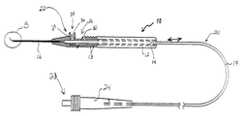
- FIG. 2is a side view of an exemplary adjustable laser probe in accordance with one embodiment of the present invention.
- FIG. 2Ais an enlarged view of area B of FIG. 2 ;
- FIG. 2Bis a front end view of the laser probe of FIG. 2 ;
- FIG. 3is a top view of the laser probe of FIG. 2 ;
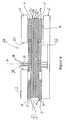
- FIG. 4is a partial cross-sectional view of the probe of FIG. 2 , taken along line 4 - 4 of FIG. 3 ;
- FIG. 5is an enlarged side view of the laser probe of FIG. 2 ;
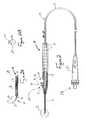
- FIG. 6is a side view of an alternate embodiment of a laser probe in accordance with the present invention.
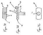
- FIGS. 7A-7Care top, side and bottom views of an alternative embodiment of the button of the laser probe.
- FIG. 8is a side view of an alternative embodiment of a laser probe that includes the button of FIGS. 7A-7C ;
- FIG. 9is a front end view of the laser probe of FIG. 8 .
- the present inventionprovides a laser probe providing adjustability between straight and curved configurations that eliminates disadvantages associated with the prior art.
- This laser probeimproves the surgeon's ability to reach critical areas within the eye, provides for safer and intuitive surgical maneuverability, and allows for quick visual inspection to confirm proper probe orientation, before extension of the fiber to expose a curved tip.
- the endo ocular laser probe of the present inventioncan function as both a straight and a curved laser probe.
- the probe 10generally includes an elongated handpiece 12 and a rigid cannula 16 fixed to the handpiece 12 to prevent relative translational movement therebetween.
- An optical fiber 20 for delivering laser energyextends through channels in the handpiece 12 and cannula 16 and is supported for translational movement therein.
- a slidable button 22is fixed to the optical fiber 20 , such that the button 22 and optical fiber 20 move together in the same direction during operation.
- the button 22may be retracted relative to the handpiece 12 to retract the flexible fiber into the rigid cannula 16 , thereby straightening the fiber 20 , or the button 22 may be advanced relative to the handpiece 12 to extend the fiber 20 from the cannula 16 , thereby exposing the fiber 20 and allowing it to curl into the curved tip configuration, as shown in FIG. 2A .
- the button 22is operable to “feed” or retract the fiber relative to the cannula 16 while the cannula 16 remains fixed in position relative to the handpiece.
- Operation of the probe, and control of the fiber relative to the handpieceis thereby improved in a manner that is less likely to cause damage to a patient's occular tissue during quick withdrawal from the eye as when a patient startles under anesthesia, etc. More specifically, retraction of the both the button 22 and the handpiece 12 in the same direction will cause the fiber to be retracted into the cannula 16 . This causes the fiber's tip to be straightened during withdrawal from the eye, thereby preventing damage to ocular tissue.
- the fiberis selectively positioned relative to the button 22 to cause the button to act as a visual indicator of the direction in which the fiber will extend from the cannula, as shown in FIGS. 2A and 2B .
- the button 22may be specially configured with an enlarged head portion 40 to enhance grippability and smooth operation of the button, as best shown in FIGS. 8 and 9 .
- the optical fiber 20is a conventional type optical fiber. For example, two and one half (2.50) meters of length of a quartz optical fiber having a 200 micron diameter, including the light transmitting core 20 a , a conventional buffer 20 b and cladding 20 c , has been found suitable (see FIG. 4 ).
- additional claddingsuch as a PVC sleeve 19 , may be applied over the fiber/buffer/cladding to provide added durability, as best shown in FIGS. 2 , 3 and 4 .
- optical fibersare typically straight or substantially straight when in a relaxed state.
- the diameter of the fibermay be selected according to the internal diameter of the cannula 16 , or as otherwise necessary to be compatible with the desired incision size.
- the optical fiber 20is preferably terminated at its proximal end 23 with a suitable connector, such as SMA connector 24 , for connection to a laser source device, as shown in FIGS. 3 and 4 . This may involve bonding the optical fiber 20 and/or any cladding to the connector by a suitable adhesive, such as cyanoacrylate, or as otherwise known in the art.
- the handpiece 12defines an internal channel 14 extending therethrough this is dimensioned to receive the optical fiber, including the optical fiber's cladding, while permitting translational movement of the clad fiber within the channel 14 without substantial friction or other interference, as best shown in FIGS. 2-4 .
- the handpiece 12preferably defines a slotted portion 26 , as generally known for prior art probes, as disclosed in U.S. Pat. No. 6,572,608 to Lee, and as shown in FIGS. 2 , 3 and 4 .
- the slotted portion 26has a front wall 28 and a rear wall 30 for limiting translational movement of the button 22 .
- the handpiece 12may include external ridges 13 to facilitate secure grasping of the probe, as best shown in FIGS. 2 and 3 .
- the cannula 16is rigid and is fixed to the handpiece 12 to prevent relative movement therebetween, as best shown in FIGS. 2 and 4 .
- the cannula 16defines an internal channel 18 substantially aligned with the channel 14 of the handpiece 12 and dimensioned to receive the optical fiber 20 , including the core 20 a , buffer 20 b and cladding 20 c , as covered by a resiliently deformable tube 21 capable of resiliently deforming between a bent/curved state and a straight state, so as to bend and straighten an otherwise straight optical fiber, as discussed further below.
- the rigid cannula 16may be made of any suitable material, such as stainless steel.
- the cannula 16may have any desired external diameter, such as to be compatible with a 20 g or 25 g stab incision commonly used in vitreoretinal surgery.
- friction-reducing materialsuch as Teflon (polytetrafluoroethylene) or polyamide coating or tubing 17 , is provided on or within an inner surface of the cannula 16 , to reduce friction between the cannula 16 and the fiber 20 , etc., and thereby facilitate extension and retraction of the fiber relative to the cannula 16 , as best shown in FIGS. 2A and 4 .
- Teflon tubing 17may be adhered to the internal surface of the cannula 16 by cyanoacrylate.
- FIG. 6Such an alternative embodiment is shown in FIG. 6 .
- the inner surface of the cannula 16 , the fiber 20 , and any flexible tube 21should be dimensioned to fit closely to present a substantially closed area at the distal tip 15 of the cannula 16 to prevent fluids from the eye or surgical procedure, etc. from entering the cannula 16 , as best shown in FIGS. 2A , 3 and 5 .
- the distal end portion 25 of the optical fiber 20is enclosed in a resiliently deformable flexible tube 21 that has been pre-bent to an angle of about 90 degrees, such that the tube may be straightened, and yet will resiliently return to its pre-bent configuration, as best shown in FIGS. 2A and 4 .
- a nitinol tube 21has been found suitable for this purpose.
- Nitinolan acronym for Nickel Titanium Naval Ordnance Laboratory, is well known in the art, and describes a family of intermetallic materials that contain a nearly equal mixture of nickel (approx. 55 wt. %) and titanium. Other elements can be added to adjust or “tune” the material properties.
- Nitinolexhibits unique behavior, particularly shape memory, which is suitable for the flexible tube 21 .
- Any other resiliently deformable materialsuch as a variety of plastic materials may be used, as will be appreciated by those skilled in the art.
- the flexible tube 21is preferably bonded to the optical fiber 20 , or more specificially to the fiber's outer cladding 20 c , e.g. using a suitable adhesive such as cyanoacrylate, as best shown in FIG. 4 .
- the flexible tube 21may be bonded with adhesive to the optical fiber 20 only at discrete points, e.g. adjacent the distal and proximal ends of the tube 21 , to permit bending of the optical fiber 20 and flexible tube 21 along their lengths.
- the flexible tube 21may enclose a length of the fiber extending from the distal end portion 25 to a portion just before (as shown in FIG. 4 , or just after the point of attachment of the button 22 .
- the button 22is fixed to the optical fiber 20 such that movement of the button 22 causes movement of the fiber in a like direction.
- a length of the optical fiber 20is stripped of its outer cladding 19 (typically a PVC material), and is enclosed in a rigid sleeve 32 , such as stainless steel sleeve 32 , as best shown in FIG. 4 .
- This rigid sleeve 32protects the integrity of the fiber 20 to prevent damage from attachment of the button 22 and advancing of the set screw 36 .
- the rigid sleeve 32supports/stiffens the otherwise flexable to premit the fibres to be pushed/advanced from the handle with damage to the fibres, undue bending of the fiber, jamming of the fiber, etc.
- the optical fiber 20(including any buffer 20 b or cladding 20 c ) may be attached to the sleeve 32 by cyanoacrylate adhesive or other suitable means.
- the button 22has a central bore 34 for receiving a threaded set screw 36 that can be advanced to fixedly attach the button 22 to the sleeve 32 , as best shown in FIGS. 2 , 3 , 4 and 5 .
- the button 22may be adhesively or otherwise attached directly to the optical fiber 20 (or a portion thereof), without the need for a sleeve 32 or a set screw 36 . Accordingly, the button 22 , sleeve 32 , flexible tube 21 and optical fiber 20 are fixed together such that longitudinal movement of the button 22 causes longitudinal movement of the optical fiber 20 , etc. in a like direction.
- the optical fiber 20extends through the channel 14 of the handpiece 12 and into the cannula 16 and is supported for translational movement therein, as best shown in FIGS. 2 and 4 .
- the button 22rides within the slotted portion 26 of the handpiece 12 such that it is longitudinally moveable from an advanced position adjacent the front wall 28 , in which the fiber extends from the cannula 16 , as shown in FIGS. 2 , 3 , 4 and 5 and a retracted position adjacent the rear wall 30 , in which the fiber is enclosed within the cannula 16 .
- the button 22has a substantially cylindrical stem portion 38 joined to the fiber 20 (and sleeve 32 ) and extending in a radial direction relative to an axis of the cannula 16 , and a head portion 40 joined to the stem portion 38 , as shown in FIG. 7A-9 .
- the head portionis enlarged to have having a top surface 42 area greater than a cross-sectional area of the stem portion 38 .
- the top surfacehas a length and a width that are both greater than a length and width of the stem portion, as best shown in FIGS. 7B , 7 C, 8 and 9 .
- the top surface 42may be configured with ridges 44 , as best shown in FIGS. 7A , 7 B and 8 .
- the enlarged head 40 and ridges 44enhance grip (friction relative to a surgeon's finger) and tend to facilitate smooth operation of the button.
- the button 22 and handpiece 12are preferably constructed of dissimilar materials (e.g. a Delrin (acetal resin) handpiece 12 and Polyetheretherketone (PEEK) button 22 ) to further enhance smooth operation.
- Thiscan be particularly advantageous when friction reducing material 19 is not provided in the cannula 16 , which results in increased friction in the cannula 16 .
- Such an embodimentmay be advantageous in small gauge (25 g) instruments in which such material 19 may be omitted for manufacturing or other reasons, such as the 25 g embodiment is shown in FIG. 6 .
- the flexible tube 21when the distal end 25 of the optical fiber 20 is assembled within the handpiece 12 , the flexible tube 21 protrudes from the cannula 16 to form the desired bend, e.g. a bend ranging from approximately 0° to approximately 90°, with a radius of approximately 0.1 to approximately 0.25 inches.
- the flexible tube 21is mounted on the optical fiber 20 and/or the optical fiber 20 is positioned relative to the handpiece 12 , such that the optical fiber 20 will bend substantially in a central plane of the button 22 , e.g. the plane of cross-section of FIGS. 2 and 8 , and preferably toward the user-actuatable/head 40 portion of the button 22 , as shown in FIGS. 2A , 2 B, 8 and 9 .
- the distal end portion 25extends substantially within a plane when in an extended position
- the button 22extends in a radial direction relative to an axis of the cannula 16 such that the radial direction extends substantially within the same plane, in substantially the same direction, such that the fiber bends toward the button 22 as shown in FIGS. 2A , 2 B, 8 and 9 , rather than away from the button as shown in FIG. 3 of U.S. Pat. No. 6,572,608.
- This positioning relationship between the flexible tube 21 and the button 22provides the surgeon with a visual and tactile indication as to the direction in which the fiber 20 will bend when extended from the cannula 16 .
- the button 11provides a visual indication, while the distal end portion 25 is retracted and housed within the cannula 16 , of where and in which direction the distal end portion 25 of the fiber 20 will extend when the button is advanced. This allows the surgeon to position the handpiece appropriately before extending the distal end portion to prevent damage to ocular tissue, etc. Additionally, should the surgeon need to adjust the button 22 when working inferio nasally, the button 22 will remain readily accessible as a result of the orientation of the button relative to the direction of curvature of the distal end portion of the fiber 20 .
- the button 22is positioned relative to the optical fiber 20 and handpiece 12 such that there is no exposure of the optical fiber 20 or flexible tube 21 beyond the cannula 16 when the button 22 is completely retracted.
- the probe 10functions such that when the button 22 is moved distally (advanced), the optical fiber 20 advances and flexes toward its pre-bent curved shape, up to about 90 degrees and in line with the button 22 .
- the optical fiber 20retracts into the non-flexible, stationary cannula 16 attached to the handpiece.
- the handpiece 12 and the optical fiber's external cladding 19are made of translucent materials.
- white Delrin (acetal resin) and white PVChave been found to be suitable for the handpiece and cladding, respectively.
- Thisallows for visual inspection of the optical fiber/probe for defects or discontinuities in the optical fiber or inconsistencies in performance when laser source is used that propagates light of a wavelength visible to the human eye.
- defects or discontinuitieswill allow escape of some laser light, which will be readily apparent upon visual inspection as a glow at the point of the defect, e.g. a green glow when a green argon laser is used.
- the present inventionprovides a laser probe that does not require the surgeon's finger to remain on the button at all times, as is recommended for prior art probes, and yet the longitudinal position and directional orientation of the distal end of the optical fiber remains satisfactorily stable and/or predictable. Additionally, the inventive laser probe allows for the retraction of the laser fiber by retracting the button, an intuitive movement, followed by retraction of the instrument from the eye.
- the laser probeis therefore adjustable in that it allows for operation in both straight and curved tip configurations, intuitive in that retracting the button retracts the optical fiber, stable in that the stationary sheath alleviates the need for the surgeon to maintain a finger positioned on the slidable button, informative in that it can be configured such that the button position provides a visual or tactile indication of the direction in which the flexible laser fiber will extend, universal in that it can be configured with any suitable connector for attachment to any suitable laser source, versatile in that it can be produced with cannulas of various sized to accommodate 20 g, 25 g or other desired tip sizes, and visually verifiable in that the laser probe and/or fiber cladding can be constructed of a translucent material to allow for inspection for escape of light in order to detect any functionality issues with the probe, such as broken fibers, tissue coagulation on the probe tip, or a faulty laser source device.
Landscapes
- Health & Medical Sciences (AREA)
- Life Sciences & Earth Sciences (AREA)
- Surgery (AREA)
- Ophthalmology & Optometry (AREA)
- Physics & Mathematics (AREA)
- Animal Behavior & Ethology (AREA)
- General Health & Medical Sciences (AREA)
- Biomedical Technology (AREA)
- Heart & Thoracic Surgery (AREA)
- Optics & Photonics (AREA)
- Veterinary Medicine (AREA)
- Nuclear Medicine, Radiotherapy & Molecular Imaging (AREA)
- Engineering & Computer Science (AREA)
- Public Health (AREA)
- Vascular Medicine (AREA)
- Electromagnetism (AREA)
- Otolaryngology (AREA)
- Medical Informatics (AREA)
- Molecular Biology (AREA)
- Laser Surgery Devices (AREA)
Abstract
Description
Claims (24)
Priority Applications (1)
| Application Number | Priority Date | Filing Date | Title |
|---|---|---|---|
| US11/035,694US7766904B2 (en) | 2003-01-31 | 2005-01-14 | Adjustable laser probe for use in vitreoretinal surgery |
Applications Claiming Priority (3)
| Application Number | Priority Date | Filing Date | Title |
|---|---|---|---|
| US44406003P | 2003-01-31 | 2003-01-31 | |
| US76535004A | 2004-01-27 | 2004-01-27 | |
| US11/035,694US7766904B2 (en) | 2003-01-31 | 2005-01-14 | Adjustable laser probe for use in vitreoretinal surgery |
Related Parent Applications (1)
| Application Number | Title | Priority Date | Filing Date |
|---|---|---|---|
| US76535004AContinuation | 2003-01-31 | 2004-01-27 |
Publications (2)
| Publication Number | Publication Date |
|---|---|
| US20050154379A1 US20050154379A1 (en) | 2005-07-14 |
| US7766904B2true US7766904B2 (en) | 2010-08-03 |
Family
ID=34742782
Family Applications (1)
| Application Number | Title | Priority Date | Filing Date |
|---|---|---|---|
| US11/035,694Active2026-07-13US7766904B2 (en) | 2003-01-31 | 2005-01-14 | Adjustable laser probe for use in vitreoretinal surgery |
Country Status (1)
| Country | Link |
|---|---|
| US (1) | US7766904B2 (en) |
Cited By (73)
| Publication number | Priority date | Publication date | Assignee | Title |
|---|---|---|---|---|
| US20090182313A1 (en)* | 2008-01-15 | 2009-07-16 | Jack Robert Auld | Targeted Illumination For Surgical Instrument |
| US20130090635A1 (en)* | 2011-10-10 | 2013-04-11 | Fouad Mansour | Probes for Use in Ophthalmic and Vitreoretinal Surgery |
| CN103124532A (en)* | 2010-08-13 | 2013-05-29 | 爱尔康研究有限公司 | Dual Mode Illumination for Surgical Instruments |
| US8678593B2 (en) | 2010-10-26 | 2014-03-25 | Alcon Research, Ltd. | Ophthalmoscopic contact lens |
| US8821444B2 (en) | 2011-10-03 | 2014-09-02 | Katalyst Surgical, Llc | Multi-utility surgical instrument |
| US8837883B2 (en) | 2011-09-23 | 2014-09-16 | Alcon Research, Ltd. | Shaping laser beam launches into optical fibers to yield specific output effects |
| US8840607B2 (en) | 2011-12-23 | 2014-09-23 | Katalyst Surgical, Llc | Steerable laser probe |
| US8840605B2 (en) | 2011-09-02 | 2014-09-23 | Katalyst Surgical, Llc | Steerable laser probe |
| US8951245B2 (en) | 2012-05-09 | 2015-02-10 | Katalyst Surgical, Llc | Steerable laser probe |
| US8968277B2 (en) | 2011-12-09 | 2015-03-03 | Katalyst Surgical, Llc | Steerable laser probe |
| US9023020B2 (en) | 2012-06-06 | 2015-05-05 | Katalyst Surgical, Llc | Steerable laser probe |
| US9023019B2 (en) | 2012-05-10 | 2015-05-05 | Katalyst Surgical, Llc | Steerable laser probe |
| US9039686B2 (en) | 2012-04-19 | 2015-05-26 | Katalyst Surgical, Llc | Steerable laser probe |
| US9089399B2 (en) | 2011-09-17 | 2015-07-28 | Katalyst Surgical, Llc | Steerable laser probe |
| US9107682B2 (en) | 2011-11-03 | 2015-08-18 | Katalyst Surgical, Llc | Steerable laser probe |
| US9113995B2 (en) | 2012-05-08 | 2015-08-25 | Katalyst Surgical, Llc | Steerable laser probe |
| US9138350B2 (en) | 2011-10-17 | 2015-09-22 | Katalyst Surgical, Llc | Steerable laser probe |
| US9149389B2 (en) | 2012-08-31 | 2015-10-06 | Katalyst Surgical, Llc | Microsurgical handle and instrument |
| US9168174B2 (en) | 2012-05-25 | 2015-10-27 | Ojai Retinal Technology, Llc | Process for restoring responsiveness to medication in tissue of living organisms |
| US9204995B2 (en) | 2013-03-12 | 2015-12-08 | Katalyst Surgical, Llc | Membrane removing forceps |
| US9216060B2 (en) | 2012-08-14 | 2015-12-22 | Katalyst Surgical, Llc | Steerable laser probe |
| US9216111B2 (en) | 2012-09-24 | 2015-12-22 | Katalyst Surgical, Llc | Steerable laser probe |
| US9226762B2 (en) | 2012-11-07 | 2016-01-05 | Katalyst Surgical, Llc | Atraumatic microsurgical forceps |
| US9226794B2 (en) | 2012-09-23 | 2016-01-05 | Katalyst Surgical, Llc | Steerable laser probe |
| US9226855B2 (en) | 2012-09-06 | 2016-01-05 | Katalyst Surgical, Llc | Steerable laser probe |
| US9233022B2 (en) | 2012-08-06 | 2016-01-12 | Katalyst Surgical, Llc | Steerable laser probe |
| US9232975B2 (en) | 2012-09-05 | 2016-01-12 | Katalyst Surgical, Llc | Steerable laser probe |
| US9247951B1 (en) | 2015-08-20 | 2016-02-02 | Katalyst Surgical, Llc | Microsurgical handle and instrument |
| US20160051335A1 (en)* | 2014-08-25 | 2016-02-25 | Peregrine Surgical Ltd. | Microsurgical instrument |
| US9335455B2 (en) | 2012-05-30 | 2016-05-10 | Cygnus, LP | Extended tip laser and illumination probe for retina surgery |
| US9345542B2 (en) | 2012-09-11 | 2016-05-24 | Katalyst Surgical, Llc | Steerable laser probe |
| US9351875B2 (en) | 2012-09-12 | 2016-05-31 | Katalyst Surgical, Llc | Steerable laser probe |
| US9364982B2 (en) | 2010-08-09 | 2016-06-14 | Novartis Ag | Method of manufacturing an illuminated surgical instrument |
| US9381115B2 (en) | 2012-05-25 | 2016-07-05 | Ojai Retinal Technology, Llc | System and process for retina phototherapy |
| US9381116B2 (en) | 2012-05-25 | 2016-07-05 | Ojai Retinal Technology, Llc | Subthreshold micropulse laser prophylactic treatment for chronic progressive retinal diseases |
| US9428254B1 (en) | 2010-09-24 | 2016-08-30 | Katalyst Surgical, Llc | Microsurgical handle and instrument |
| US9427602B2 (en) | 2012-05-25 | 2016-08-30 | Ojai Retinal Technology, Llc | Pulsating electromagnetic and ultrasound therapy for stimulating targeted heat shock proteins and facilitating protein repair |
| US9433530B1 (en)* | 2015-04-24 | 2016-09-06 | Katalyst Surgical, Llc | Steerable laser probe and methods of use |
| US9474812B2 (en) | 2014-03-27 | 2016-10-25 | Katalyst Surgical, Llc | Instrument sterilization container |
| US9480600B2 (en) | 2012-06-27 | 2016-11-01 | Katalyst Surgical, Llc | Steerable laser probe |
| US9549780B2 (en) | 2012-05-13 | 2017-01-24 | Katalyst Surgical, Llc | Steerable laser probe |
| US9629645B2 (en) | 2012-10-30 | 2017-04-25 | Katalyst Surgical, Llc | Atraumatic microsurgical forceps |
| US9757536B2 (en) | 2012-07-17 | 2017-09-12 | Novartis Ag | Soft tip cannula |
| US9763830B2 (en) | 2012-10-13 | 2017-09-19 | Katalyst Surgical, Llc | Steerable laser probe |
| US9770296B2 (en) | 2012-07-31 | 2017-09-26 | Katalyst Surgical, Llc | Steerable laser probe |
| US9770298B2 (en) | 2012-08-10 | 2017-09-26 | Katalyst Surgical, Llc | Steerable laser probe |
| US9877867B2 (en) | 2012-08-01 | 2018-01-30 | Katalyst Surgical, Llc | Steerable laser probe |
| US9931246B2 (en) | 2012-10-17 | 2018-04-03 | Katalyst Surgical, Llc | Steerable laser probe |
| US9956053B2 (en) | 2016-03-04 | 2018-05-01 | Novartis Ag | Cannula with an integrated illumination feature |
| US9962291B2 (en) | 2012-05-25 | 2018-05-08 | Ojai Retinal Technology, Llc | System and process for neuroprotective therapy for glaucoma |
| US10022267B2 (en) | 2014-04-21 | 2018-07-17 | Katalyst Surgical, Llc | Method of manufacturing a microsurgical instrument tip |
| US10076671B2 (en) | 2012-05-25 | 2018-09-18 | Ojai Retinal Technology, Llc | Apparatus for retina phototherapy |
| US10201452B2 (en) | 2013-07-31 | 2019-02-12 | Katalyst Surgical, Inc. | Laser probe with a replaceable optic fiber |
| US10219947B2 (en) | 2012-05-25 | 2019-03-05 | Ojai Retinal Technology, Llc | System and process for retina phototherapy |
| US10244931B2 (en) | 2015-07-13 | 2019-04-02 | Novartis Ag | Illuminated ophthalmic infusion line and associated devices, systems, and methods |
| US10245182B2 (en) | 2015-11-14 | 2019-04-02 | Katalyst Surgical, Llc | Laser probe with replaceable optic fibers |
| US10278863B2 (en) | 2016-03-21 | 2019-05-07 | Ojai Retinal Technology, Llc | System and process for treatment of myopia |
| US10391232B2 (en) | 2014-10-10 | 2019-08-27 | Katalyst Surgical, Llc | Cannula ingress system |
| US10420460B2 (en) | 2016-09-09 | 2019-09-24 | Katalyst Surgical, Llc | Illumination probe |
| US10531908B2 (en) | 2012-05-25 | 2020-01-14 | Ojai Retinal Technology, Llc | Method for heat treating biological tissues using pulsed energy sources |
| US10596389B2 (en) | 2012-05-25 | 2020-03-24 | Ojai Retinal Technology, Llc | Process and system for utilizing energy to treat biological tissue |
| US10646113B2 (en) | 2016-09-09 | 2020-05-12 | Katalyst Surgical, Llc | Illuminated cannula |
| US10695043B2 (en) | 2017-02-21 | 2020-06-30 | Katalyst Surgical, Llc | Surgical instrument subcomponent integration by additive manufacturing |
| US10709608B2 (en) | 2016-03-21 | 2020-07-14 | Ojai Retinal Technology, Llc | System and process for prevention of myopia |
| US10709504B2 (en) | 2016-09-19 | 2020-07-14 | Katalyst Surgical, Llc | Curved laser probe with single-use optic fiber |
| US10828192B2 (en) | 2012-01-26 | 2020-11-10 | Katalyst Surgical, Llc | Surgical instrument sleeve |
| US10849640B2 (en) | 2018-05-23 | 2020-12-01 | Katalyst Surgical, Llc | Membrane aggregating forceps |
| US10874873B2 (en) | 2012-05-25 | 2020-12-29 | Ojai Retinal Technology, Llc | Process utilizing pulsed energy to heat treat biological tissue |
| US10894169B2 (en) | 2012-05-25 | 2021-01-19 | Ojai Retinal Technology, Llc | System and method for preventing or treating Alzheimer's and other neurodegenerative diseases |
| US10953241B2 (en) | 2012-05-25 | 2021-03-23 | Ojai Retinal Technology, Llc | Process for providing protective therapy for biological tissues or fluids |
| US11077318B2 (en) | 2012-05-25 | 2021-08-03 | Ojai Retinal Technology, Llc | System and process of utilizing energy for treating biological tissue |
| US11160935B2 (en) | 2016-06-16 | 2021-11-02 | Katalyst Surgical, Llc | Reusable instrument handle with single-use tip |
| US11173008B2 (en) | 2015-11-01 | 2021-11-16 | Alcon Inc. | Illuminated ophthalmic cannula |
Families Citing this family (34)
| Publication number | Priority date | Publication date | Assignee | Title |
|---|---|---|---|---|
| US6984230B2 (en)* | 2000-04-07 | 2006-01-10 | Synergetics, Inc. | Directional laser probe |
| WO2007021914A2 (en)* | 2005-08-11 | 2007-02-22 | Synergetics, Inc. | Illuminated directional laser probe |
| CN101351236B (en) | 2005-11-15 | 2013-05-29 | 约翰霍普金斯大学 | An active sleeve for biosensing and surgery |
| WO2007147905A1 (en)* | 2006-06-16 | 2007-12-27 | Arcusa Villacampa Francisco Ja | Improved disposable needle for laser-energy application |
| US20080004608A1 (en)* | 2006-06-30 | 2008-01-03 | Alcon, Inc. | Multifunction surgical probe |
| AU2007297702B2 (en)* | 2006-09-19 | 2013-04-04 | The Trustees Of Columbia University In The City Of New York | Systems, devices, and methods for surgery on a hollow anatomically suspended organ |
| US20080108979A1 (en)* | 2006-11-03 | 2008-05-08 | William Telfair | Flush Tip Illuminating Laser Probe Treatment Apparatus |
| WO2008057877A2 (en)* | 2006-11-03 | 2008-05-15 | Iridex Corporation | Shaped tip illuminating laser probe treatment apparatus |
| US20080200909A1 (en)* | 2006-11-16 | 2008-08-21 | Lawler David E | Laser fiber holder |
| FR2913192B1 (en)* | 2007-03-02 | 2010-02-26 | Optical System & Res For Ind & Science Osyris | CANNULA / FIBER OPTIC ASSEMBLY AND LASER INSTRUMENT COMPRISING SAID ASSEMBLY. |
| US7566173B2 (en)* | 2007-07-09 | 2009-07-28 | Alcon, Inc. | Multi-spot ophthalmic laser probe |
| US20090093800A1 (en)* | 2007-10-04 | 2009-04-09 | Auld Jack R | Flexible Surgical Probe |
| US20110125139A1 (en)* | 2007-10-04 | 2011-05-26 | Auld Jack R | Multi-fiber flexible surgical probe |
| EP2244784A2 (en)* | 2008-01-30 | 2010-11-03 | The Trustees of Columbia University in the City of New York | Systems, devices, and methods for robot-assisted micro-surgical stenting |
| US7815376B2 (en) | 2008-06-30 | 2010-10-19 | Intuitive Surgical Operations, Inc. | Fixture for shape-sensing optical fiber in a kinematic chain |
| US20100004642A1 (en)* | 2008-07-02 | 2010-01-07 | Lumpkin Christopher F | Selectively bendable laser fiber for surgical laser probe |
| DE102009000685B4 (en) | 2009-02-06 | 2018-10-25 | Sirona Dental Systems Gmbh | Laser Handpiece |
| BR112012012240A2 (en)* | 2009-11-24 | 2016-04-12 | Alcon Res Ltd | ophthalmic illuminator and method |
| CN102655906B (en)* | 2009-12-15 | 2015-03-25 | 爱尔康研究有限公司 | Multi-spot laser probe |
| BR112012020778A2 (en)* | 2010-02-17 | 2016-05-03 | Alcon Res Ltd | probe |
| US10213260B2 (en)* | 2011-12-01 | 2019-02-26 | Joe Denton Brown | End fire fiber arrangements with improved erosion resistance |
| US9615969B2 (en) | 2012-12-18 | 2017-04-11 | Novartis Ag | Multi-port vitrectomy probe with dual cutting edges |
| US10245181B2 (en) | 2012-12-21 | 2019-04-02 | Alcon Research, Ltd. | Grin fiber multi-spot laser probe |
| US9949876B2 (en)* | 2014-03-05 | 2018-04-24 | Cygnus LP | Small gauge instruments for micro surgery |
| US10238543B2 (en) | 2014-10-29 | 2019-03-26 | Novartis Ag | Vitrectomy probe with an optical fiber scanner |
| US9693898B2 (en) | 2014-11-19 | 2017-07-04 | Novartis Ag | Double-acting vitreous probe with contoured port |
| US10803662B2 (en) | 2015-05-22 | 2020-10-13 | The University Of North Carolina At Chapel Hill | Methods, systems, and computer readable media for transoral lung access |
| US11172988B2 (en) | 2016-01-27 | 2021-11-16 | Optical Integrity, Inc. | End fire fiber arrangements with improved erosion resistance |
| JP6405395B2 (en)* | 2017-01-25 | 2018-10-17 | 修 元山 | Ultra-thin endoscope |
| WO2019175784A1 (en)* | 2018-03-14 | 2019-09-19 | Alcon Inc. | Medical instruments with adjustable optical fiber |
| US10702638B2 (en)* | 2018-08-31 | 2020-07-07 | Njr Medical, Inc. | Tracheal and pharyngeal suction device |
| CN110301976A (en)* | 2019-06-13 | 2019-10-08 | 宋端虹 | A kind of medical endoscope laser optical fiber protecting equipment |
| US11628020B2 (en) | 2019-06-19 | 2023-04-18 | Virtuoso Surgical, Inc. | Insertable robot for minimally invasive surgery |
| WO2021076765A1 (en) | 2019-10-17 | 2021-04-22 | Intuitive Surgical Operations, Inc. | Surgical tool with nested shaft tubes |
Citations (30)
| Publication number | Priority date | Publication date | Assignee | Title |
|---|---|---|---|---|
| US4347837A (en) | 1979-09-17 | 1982-09-07 | Olympus Optical Co., Ltd. | Structure for preventing the breakage of end portions of a protective covering for the adjustable bend section of an endoscope |
| US4674497A (en) | 1984-08-15 | 1987-06-23 | Olympus Optical Co., Ltd. | Medical laser device |
| US4744360A (en) | 1986-12-18 | 1988-05-17 | Bath Patricia E | Apparatus for ablating and removing cataract lenses |
| US5172685A (en) | 1988-05-27 | 1992-12-22 | The University Of Connecticut | Endoscope and video laser camera system therefor |
| US5281214A (en)* | 1992-04-21 | 1994-01-25 | Laserscope | Disposable surgical probe having fiber diverter |
| US5300061A (en) | 1991-08-29 | 1994-04-05 | Surgical Technologies, Inc. | Laser delivery probe having a mechanically free floating sheath |
| US5372585A (en) | 1992-04-09 | 1994-12-13 | Tiefenbrun; Jonathan | Instrument and associated method for applying biologically effective composition during laparoscopic operation |
| US5469524A (en)* | 1994-05-12 | 1995-11-21 | Indigo Medical, Incorporated | Fiberoptic delivery system and method of use |
| WO1995031926A1 (en) | 1994-05-23 | 1995-11-30 | Sachdeva Rohit C I | Instrument for endoscopic-type procedures |
| US5512034A (en) | 1992-11-25 | 1996-04-30 | Finn; Miles A. | Surgical instrument including viewing optics and a ball probe |
| US5520222A (en) | 1989-10-13 | 1996-05-28 | Kabushiki Kaisha Machida Seisakusho | Bending device |
| US5549565A (en) | 1993-07-13 | 1996-08-27 | Symbiosis Corporation | Reusable surgical trocar with disposable valve assembly |
| US5603710A (en) | 1993-04-15 | 1997-02-18 | Infinitech, Inc. | Laser delivery system with soft tip |
| US5656011A (en) | 1994-04-28 | 1997-08-12 | Epflex Feinwerktechnik Gmbh | Endoscope tube system |
| US5688264A (en) | 1992-10-19 | 1997-11-18 | The University Of Miami | Laser treatment for retinal detachment |
| US5735792A (en) | 1992-11-25 | 1998-04-07 | Clarus Medical Systems, Inc. | Surgical instrument including viewing optics and an atraumatic probe |
| US5741225A (en) | 1992-08-12 | 1998-04-21 | Rita Medical Systems | Method for treating the prostate |
| US5766164A (en) | 1996-07-03 | 1998-06-16 | Eclipse Surgical Technologies, Inc. | Contiguous, branched transmyocardial revascularization (TMR) channel, method and device |
| US5807242A (en) | 1997-03-24 | 1998-09-15 | Synergetics, Inc. | Microsurgical laser probe with homogeneous laser light field |
| US5807424A (en)* | 1994-06-17 | 1998-09-15 | Hasso von Blucher | Regenerative adsorption filter bed for exhauster hoods |
| US5855577A (en)* | 1996-09-17 | 1999-01-05 | Eclipse Surgical Technologies, Inc. | Bow shaped catheter |
| DE19824796A1 (en) | 1997-06-03 | 1999-01-07 | Nec Corp | Logic circuit with glitch prevention for VLSI circuitry |
| US5993072A (en) | 1996-04-17 | 1999-11-30 | The Johns Hopkins University | Adapter assembly for connecting multiple optic fiber illuminated microsurgical instruments to a single light source |
| USRE36473E (en)* | 1994-05-12 | 1999-12-28 | Indigo Medical, Inc. | Fiberoptic delivery system and method of use |
| US6053911A (en) | 1996-11-08 | 2000-04-25 | Thomas J. Fogarty | Transvascular TMR device and method |
| US6129721A (en) | 1997-06-04 | 2000-10-10 | J. Morita Manufacturing Corporation | Medical laser treatment device and laser probe for the same |
| US6142990A (en) | 1997-02-15 | 2000-11-07 | Heidelberg Engineering Optische Messsysteme Gmbh | Medical apparatus, especially for reducing intraocular pressure |
| US6572608B1 (en)* | 1999-04-08 | 2003-06-03 | Eric T. Lee | Directional laser probe |
| US6575989B1 (en) | 1999-09-13 | 2003-06-10 | Synergetics, Inc. | Adjustable stiffness membrane scraper |
| US6984230B2 (en)* | 2000-04-07 | 2006-01-10 | Synergetics, Inc. | Directional laser probe |
Family Cites Families (2)
| Publication number | Priority date | Publication date | Assignee | Title |
|---|---|---|---|---|
| US5957916A (en)* | 1994-05-25 | 1999-09-28 | The Trustees Of Columbia University In The City Of New York | Myocardial revascularization through the endocardial surface using a laser |
| US5865831A (en)* | 1996-04-17 | 1999-02-02 | Premier Laser Systems, Inc. | Laser surgical procedures for treatment of glaucoma |
- 2005
- 2005-01-14USUS11/035,694patent/US7766904B2/enactiveActive
Patent Citations (30)
| Publication number | Priority date | Publication date | Assignee | Title |
|---|---|---|---|---|
| US4347837A (en) | 1979-09-17 | 1982-09-07 | Olympus Optical Co., Ltd. | Structure for preventing the breakage of end portions of a protective covering for the adjustable bend section of an endoscope |
| US4674497A (en) | 1984-08-15 | 1987-06-23 | Olympus Optical Co., Ltd. | Medical laser device |
| US4744360A (en) | 1986-12-18 | 1988-05-17 | Bath Patricia E | Apparatus for ablating and removing cataract lenses |
| US5172685A (en) | 1988-05-27 | 1992-12-22 | The University Of Connecticut | Endoscope and video laser camera system therefor |
| US5520222A (en) | 1989-10-13 | 1996-05-28 | Kabushiki Kaisha Machida Seisakusho | Bending device |
| US5300061A (en) | 1991-08-29 | 1994-04-05 | Surgical Technologies, Inc. | Laser delivery probe having a mechanically free floating sheath |
| US5372585A (en) | 1992-04-09 | 1994-12-13 | Tiefenbrun; Jonathan | Instrument and associated method for applying biologically effective composition during laparoscopic operation |
| US5281214A (en)* | 1992-04-21 | 1994-01-25 | Laserscope | Disposable surgical probe having fiber diverter |
| US5741225A (en) | 1992-08-12 | 1998-04-21 | Rita Medical Systems | Method for treating the prostate |
| US5688264A (en) | 1992-10-19 | 1997-11-18 | The University Of Miami | Laser treatment for retinal detachment |
| US5735792A (en) | 1992-11-25 | 1998-04-07 | Clarus Medical Systems, Inc. | Surgical instrument including viewing optics and an atraumatic probe |
| US5512034A (en) | 1992-11-25 | 1996-04-30 | Finn; Miles A. | Surgical instrument including viewing optics and a ball probe |
| US5603710A (en) | 1993-04-15 | 1997-02-18 | Infinitech, Inc. | Laser delivery system with soft tip |
| US5549565A (en) | 1993-07-13 | 1996-08-27 | Symbiosis Corporation | Reusable surgical trocar with disposable valve assembly |
| US5656011A (en) | 1994-04-28 | 1997-08-12 | Epflex Feinwerktechnik Gmbh | Endoscope tube system |
| US5469524A (en)* | 1994-05-12 | 1995-11-21 | Indigo Medical, Incorporated | Fiberoptic delivery system and method of use |
| USRE36473E (en)* | 1994-05-12 | 1999-12-28 | Indigo Medical, Inc. | Fiberoptic delivery system and method of use |
| WO1995031926A1 (en) | 1994-05-23 | 1995-11-30 | Sachdeva Rohit C I | Instrument for endoscopic-type procedures |
| US5807424A (en)* | 1994-06-17 | 1998-09-15 | Hasso von Blucher | Regenerative adsorption filter bed for exhauster hoods |
| US5993072A (en) | 1996-04-17 | 1999-11-30 | The Johns Hopkins University | Adapter assembly for connecting multiple optic fiber illuminated microsurgical instruments to a single light source |
| US5766164A (en) | 1996-07-03 | 1998-06-16 | Eclipse Surgical Technologies, Inc. | Contiguous, branched transmyocardial revascularization (TMR) channel, method and device |
| US5855577A (en)* | 1996-09-17 | 1999-01-05 | Eclipse Surgical Technologies, Inc. | Bow shaped catheter |
| US6053911A (en) | 1996-11-08 | 2000-04-25 | Thomas J. Fogarty | Transvascular TMR device and method |
| US6142990A (en) | 1997-02-15 | 2000-11-07 | Heidelberg Engineering Optische Messsysteme Gmbh | Medical apparatus, especially for reducing intraocular pressure |
| US5807242A (en) | 1997-03-24 | 1998-09-15 | Synergetics, Inc. | Microsurgical laser probe with homogeneous laser light field |
| DE19824796A1 (en) | 1997-06-03 | 1999-01-07 | Nec Corp | Logic circuit with glitch prevention for VLSI circuitry |
| US6129721A (en) | 1997-06-04 | 2000-10-10 | J. Morita Manufacturing Corporation | Medical laser treatment device and laser probe for the same |
| US6572608B1 (en)* | 1999-04-08 | 2003-06-03 | Eric T. Lee | Directional laser probe |
| US6575989B1 (en) | 1999-09-13 | 2003-06-10 | Synergetics, Inc. | Adjustable stiffness membrane scraper |
| US6984230B2 (en)* | 2000-04-07 | 2006-01-10 | Synergetics, Inc. | Directional laser probe |
Cited By (172)
| Publication number | Priority date | Publication date | Assignee | Title |
|---|---|---|---|---|
| US9510848B2 (en) | 2008-01-15 | 2016-12-06 | Novartis Ag | Targeted illumination for surgical instrument |
| US9402643B2 (en) | 2008-01-15 | 2016-08-02 | Novartis Ag | Targeted illumination for surgical instrument |
| US20090182313A1 (en)* | 2008-01-15 | 2009-07-16 | Jack Robert Auld | Targeted Illumination For Surgical Instrument |
| US9510847B2 (en) | 2008-01-15 | 2016-12-06 | Novartis Ag | Targeted illumination for surgical instrument |
| US9364982B2 (en) | 2010-08-09 | 2016-06-14 | Novartis Ag | Method of manufacturing an illuminated surgical instrument |
| CN103124532B (en)* | 2010-08-13 | 2016-03-16 | 爱尔康研究有限公司 | Dual Mode Illumination for Surgical Instruments |
| CN103124532A (en)* | 2010-08-13 | 2013-05-29 | 爱尔康研究有限公司 | Dual Mode Illumination for Surgical Instruments |
| US10299816B2 (en) | 2010-09-24 | 2019-05-28 | Katalyst Surgical, Llc | Microsurgical handle and instrument |
| US9782189B2 (en) | 2010-09-24 | 2017-10-10 | Katalyst Surgical, Llc | Microsurgical handle and instrument |
| US9428254B1 (en) | 2010-09-24 | 2016-08-30 | Katalyst Surgical, Llc | Microsurgical handle and instrument |
| US8678593B2 (en) | 2010-10-26 | 2014-03-25 | Alcon Research, Ltd. | Ophthalmoscopic contact lens |
| US8840605B2 (en) | 2011-09-02 | 2014-09-23 | Katalyst Surgical, Llc | Steerable laser probe |
| US9757277B2 (en) | 2011-09-02 | 2017-09-12 | Katalyst Surgical, Llc | Steerable laser probe |
| US10695221B2 (en) | 2011-09-02 | 2020-06-30 | Katalyst Surgical, Llc | Steerable laser probe |
| US9433531B1 (en)* | 2011-09-17 | 2016-09-06 | Katalyst Surgical, Llc | Steerable laser probe |
| US9782294B2 (en) | 2011-09-17 | 2017-10-10 | Katalyst Surgical, Llc | Steerable laser probe |
| US9089399B2 (en) | 2011-09-17 | 2015-07-28 | Katalyst Surgical, Llc | Steerable laser probe |
| US9326892B2 (en) | 2011-09-17 | 2016-05-03 | Katalyst Surgical, Llc | Steerable laser probe |
| US9237966B2 (en) | 2011-09-17 | 2016-01-19 | Katalyst Surgical, Llc | Steerable laser probe |
| US8837883B2 (en) | 2011-09-23 | 2014-09-16 | Alcon Research, Ltd. | Shaping laser beam launches into optical fibers to yield specific output effects |
| US9415156B2 (en) | 2011-10-03 | 2016-08-16 | Katalyst Surgical, Llc | Multi-utility surgical instrument |
| US10478165B2 (en) | 2011-10-03 | 2019-11-19 | Katalyst Surgical, Llc | Multi-utility surgical instrument |
| US9750488B2 (en) | 2011-10-03 | 2017-09-05 | Katalyst Surgical, Llc | Multi-utility surgical instrument |
| US9675330B2 (en) | 2011-10-03 | 2017-06-13 | Katalyst Surgical, Llc | Multi-utility surgical instrument |
| US8821444B2 (en) | 2011-10-03 | 2014-09-02 | Katalyst Surgical, Llc | Multi-utility surgical instrument |
| US9370447B2 (en)* | 2011-10-10 | 2016-06-21 | Cygnus LP | Probes for use in ophthalmic and vitreoretinal surgery |
| WO2013055731A1 (en)* | 2011-10-10 | 2013-04-18 | Cygnus Llc | Probes for use in ophthalmic and vitreoretinal surgery |
| US20130090635A1 (en)* | 2011-10-10 | 2013-04-11 | Fouad Mansour | Probes for Use in Ophthalmic and Vitreoretinal Surgery |
| US9138350B2 (en) | 2011-10-17 | 2015-09-22 | Katalyst Surgical, Llc | Steerable laser probe |
| US10492952B2 (en) | 2011-10-17 | 2019-12-03 | Katalyst Surgical, Llc | Steerable laser probe |
| US10098786B2 (en) | 2011-10-17 | 2018-10-16 | Katalyst Surgical, Llc | Steerable laser probe |
| US9782295B2 (en) | 2011-10-17 | 2017-10-10 | Katalyst Surgical, Llc | Steerable laser probe |
| US9474650B2 (en) | 2011-10-17 | 2016-10-25 | Katalyst Surgical, Llc | Steerable laser probe |
| US10709609B2 (en) | 2011-11-03 | 2020-07-14 | Katalyst Surgical, Llc | Steerable laser probe |
| US9554942B1 (en) | 2011-11-03 | 2017-01-31 | Katalyst Surgical, Llc | Steerable laser probe |
| US9107682B2 (en) | 2011-11-03 | 2015-08-18 | Katalyst Surgical, Llc | Steerable laser probe |
| US9398980B2 (en) | 2011-11-03 | 2016-07-26 | Katalyst Surgical, Llc | Steerable laser probe |
| US9717630B1 (en) | 2011-11-03 | 2017-08-01 | Katalyst Surgical, Llc | Steerable laser probe |
| US9889044B1 (en) | 2011-11-03 | 2018-02-13 | Katalyst Surgical, Llc | Steerable laser probe |
| US9408666B1 (en) | 2011-12-09 | 2016-08-09 | Katalyst Surgical, Llc | Steerable laser probe |
| US9132035B2 (en) | 2011-12-09 | 2015-09-15 | Katalyst Surgical, Llc | Steerable laser probe |
| US8968277B2 (en) | 2011-12-09 | 2015-03-03 | Katalyst Surgical, Llc | Steerable laser probe |
| US9872731B2 (en) | 2011-12-09 | 2018-01-23 | Katalyst Surgical, Llc | Steerable laser probe |
| US10188373B2 (en) | 2011-12-23 | 2019-01-29 | Katalyst Surgical, Llc | Steerable laser probe |
| US9119702B2 (en) | 2011-12-23 | 2015-09-01 | Katalyst Surgical, Llc | Steerable laser probe |
| US9693906B2 (en) | 2011-12-23 | 2017-07-04 | Katalyst Surgical, Llc | Steerable laser probe |
| US8840607B2 (en) | 2011-12-23 | 2014-09-23 | Katalyst Surgical, Llc | Steerable laser probe |
| US9855026B2 (en) | 2011-12-23 | 2018-01-02 | Katalyst Surgical, Llc | Steerable laser probe |
| US10828192B2 (en) | 2012-01-26 | 2020-11-10 | Katalyst Surgical, Llc | Surgical instrument sleeve |
| US10052232B2 (en) | 2012-04-19 | 2018-08-21 | Katalyst Surgical, Llc | Steerable laser probe |
| US9265657B2 (en) | 2012-04-19 | 2016-02-23 | Katalyst Surgical, Llc | Steerable laser probe |
| US9039686B2 (en) | 2012-04-19 | 2015-05-26 | Katalyst Surgical, Llc | Steerable laser probe |
| US9775745B2 (en) | 2012-05-08 | 2017-10-03 | Katalyst Surgical, Llc | Steerable laser probe |
| US9113995B2 (en) | 2012-05-08 | 2015-08-25 | Katalyst Surgical, Llc | Steerable laser probe |
| US10376315B2 (en) | 2012-05-08 | 2019-08-13 | Katalyst Surgical, Llc | Steerable laser probe |
| US9572714B2 (en) | 2012-05-08 | 2017-02-21 | Katalyst Surgical, Llc | Steerable laser probe |
| US8951245B2 (en) | 2012-05-09 | 2015-02-10 | Katalyst Surgical, Llc | Steerable laser probe |
| US9925089B2 (en) | 2012-05-09 | 2018-03-27 | Katalyst Surgical, Llc | Steerable laser probe |
| US9433529B2 (en) | 2012-05-09 | 2016-09-06 | Katalyst Surgical, Llc | Steerable laser probe |
| US10245183B2 (en) | 2012-05-09 | 2019-04-02 | Katalyst Surgical, Llc | Steerable laser probe |
| US10052230B2 (en) | 2012-05-10 | 2018-08-21 | Katalyst Surgical, Llc | Steerable laser probe |
| US9023019B2 (en) | 2012-05-10 | 2015-05-05 | Katalyst Surgical, Llc | Steerable laser probe |
| US9351876B1 (en) | 2012-05-10 | 2016-05-31 | Katalyst Surgical, Llc | Steerable laser probe |
| US9226854B2 (en) | 2012-05-10 | 2016-01-05 | Katalyst Surgical, Llc | Steerable laser probe |
| US10307208B2 (en) | 2012-05-13 | 2019-06-04 | Katalyst Surgical, Llc | Steerable laser probe |
| US11234766B2 (en) | 2012-05-13 | 2022-02-01 | Gregg D Scheller | Steerable laser probe |
| US9549780B2 (en) | 2012-05-13 | 2017-01-24 | Katalyst Surgical, Llc | Steerable laser probe |
| US10952901B2 (en) | 2012-05-25 | 2021-03-23 | Ojai Retinal Technology, Llc | System and process for retina phototherapy |
| US9381115B2 (en) | 2012-05-25 | 2016-07-05 | Ojai Retinal Technology, Llc | System and process for retina phototherapy |
| US10278865B2 (en) | 2012-05-25 | 2019-05-07 | Ojai Retinal Technology, Llc | Process for neuroprotective therapy for glaucoma |
| US9962291B2 (en) | 2012-05-25 | 2018-05-08 | Ojai Retinal Technology, Llc | System and process for neuroprotective therapy for glaucoma |
| US12377283B2 (en) | 2012-05-25 | 2025-08-05 | Ojai Retinal Technology, Llc | System and process of utilizing microwave energy for treating biological tissue |
| US10299961B2 (en) | 2012-05-25 | 2019-05-28 | Ojai Retinal Technology, Llc | System for neuroprotective therapy for glaucoma |
| US10307294B2 (en) | 2012-05-25 | 2019-06-04 | Ojai Retinal Technology, Llc | System and process for neuroprotective therapy for glaucoma |
| US10238542B2 (en) | 2012-05-25 | 2019-03-26 | Ojai Retinal Technology, Llc | System and process for retina phototherapy |
| US10219947B2 (en) | 2012-05-25 | 2019-03-05 | Ojai Retinal Technology, Llc | System and process for retina phototherapy |
| US9427602B2 (en) | 2012-05-25 | 2016-08-30 | Ojai Retinal Technology, Llc | Pulsating electromagnetic and ultrasound therapy for stimulating targeted heat shock proteins and facilitating protein repair |
| US9381116B2 (en) | 2012-05-25 | 2016-07-05 | Ojai Retinal Technology, Llc | Subthreshold micropulse laser prophylactic treatment for chronic progressive retinal diseases |
| US10953241B2 (en) | 2012-05-25 | 2021-03-23 | Ojai Retinal Technology, Llc | Process for providing protective therapy for biological tissues or fluids |
| US10363171B2 (en) | 2012-05-25 | 2019-07-30 | Ojai Retinal Technology, Llc | System and process for retina phototherapy |
| US10531908B2 (en) | 2012-05-25 | 2020-01-14 | Ojai Retinal Technology, Llc | Method for heat treating biological tissues using pulsed energy sources |
| US9168174B2 (en) | 2012-05-25 | 2015-10-27 | Ojai Retinal Technology, Llc | Process for restoring responsiveness to medication in tissue of living organisms |
| US10117777B2 (en) | 2012-05-25 | 2018-11-06 | Ojai Retinal Technology, Llc | System for neuroprotective therapy for glaucoma |
| US10894169B2 (en) | 2012-05-25 | 2021-01-19 | Ojai Retinal Technology, Llc | System and method for preventing or treating Alzheimer's and other neurodegenerative diseases |
| US11077318B2 (en) | 2012-05-25 | 2021-08-03 | Ojai Retinal Technology, Llc | System and process of utilizing energy for treating biological tissue |
| US10596389B2 (en) | 2012-05-25 | 2020-03-24 | Ojai Retinal Technology, Llc | Process and system for utilizing energy to treat biological tissue |
| US10076671B2 (en) | 2012-05-25 | 2018-09-18 | Ojai Retinal Technology, Llc | Apparatus for retina phototherapy |
| US11033749B2 (en) | 2012-05-25 | 2021-06-15 | Ojai Retinal Technology, Llc | Process utilizing pulsed energy to heat treat biological tissue |
| US10285859B2 (en) | 2012-05-25 | 2019-05-14 | Ojai Retinal Technology, Llc | System for performing retina photostimulation |
| US10874873B2 (en) | 2012-05-25 | 2020-12-29 | Ojai Retinal Technology, Llc | Process utilizing pulsed energy to heat treat biological tissue |
| US9335455B2 (en) | 2012-05-30 | 2016-05-10 | Cygnus, LP | Extended tip laser and illumination probe for retina surgery |
| US9925090B2 (en) | 2012-06-06 | 2018-03-27 | Katalyst Surgical, Llc | Steerable laser probe |
| US9480602B2 (en) | 2012-06-06 | 2016-11-01 | Katalyst Surgical, Llc | Steerable laser probe |
| US9023020B2 (en) | 2012-06-06 | 2015-05-05 | Katalyst Surgical, Llc | Steerable laser probe |
| US9480600B2 (en) | 2012-06-27 | 2016-11-01 | Katalyst Surgical, Llc | Steerable laser probe |
| US9757536B2 (en) | 2012-07-17 | 2017-09-12 | Novartis Ag | Soft tip cannula |
| US10070923B2 (en) | 2012-07-31 | 2018-09-11 | Katalyst Surgical, Llc | Steerable laser probe |
| US9770296B2 (en) | 2012-07-31 | 2017-09-26 | Katalyst Surgical, Llc | Steerable laser probe |
| US9877867B2 (en) | 2012-08-01 | 2018-01-30 | Katalyst Surgical, Llc | Steerable laser probe |
| US9233022B2 (en) | 2012-08-06 | 2016-01-12 | Katalyst Surgical, Llc | Steerable laser probe |
| US10004640B2 (en) | 2012-08-06 | 2018-06-26 | Katalyst Surgical, Llc | Steerable laser probe |
| US9770298B2 (en) | 2012-08-10 | 2017-09-26 | Katalyst Surgical, Llc | Steerable laser probe |
| US9888965B2 (en) | 2012-08-10 | 2018-02-13 | Katalyst Surgical, Llc | Steerable laser probe |
| US11045254B2 (en) | 2012-08-10 | 2021-06-29 | Katalyst Surgical, Llc | Steerable laser probe |
| US10357313B2 (en) | 2012-08-10 | 2019-07-23 | Katalyst Surgical, Llc | Steerable laser probe |
| US9681918B2 (en) | 2012-08-14 | 2017-06-20 | Katalyst Surgical, Llc | Steerable laser probe |
| US9849035B2 (en) | 2012-08-14 | 2017-12-26 | Katalyst Surgical, Llc | Steerable laser probe |
| US9216060B2 (en) | 2012-08-14 | 2015-12-22 | Katalyst Surgical, Llc | Steerable laser probe |
| US10335235B2 (en) | 2012-08-14 | 2019-07-02 | Katalyst Surgical, Llc | Steerable laser probe |
| US9149389B2 (en) | 2012-08-31 | 2015-10-06 | Katalyst Surgical, Llc | Microsurgical handle and instrument |
| US9173772B1 (en) | 2012-08-31 | 2015-11-03 | Katalyst Surgical, Llc | Microsurgical handle and instrument |
| US9232975B2 (en) | 2012-09-05 | 2016-01-12 | Katalyst Surgical, Llc | Steerable laser probe |
| US10076444B2 (en) | 2012-09-05 | 2018-09-18 | Katalyst Surgical, Llc | Steerable laser probe |
| US9770364B2 (en) | 2012-09-05 | 2017-09-26 | Katalyst Surgical, Llc | Steerable laser probe |
| US9549853B2 (en) | 2012-09-05 | 2017-01-24 | Katalyst Surgical, Llc | Steerable laser probe |
| US9901484B1 (en) | 2012-09-06 | 2018-02-27 | Katalyst Surgical, Llc | Steerable laser probe |
| US9775744B2 (en) | 2012-09-06 | 2017-10-03 | Katalyst Surgical, Llc | Steerable laser probe |
| US9539142B2 (en) | 2012-09-06 | 2017-01-10 | Katalyst Surgical, Llc | Steerable laser probe |
| US10792187B2 (en) | 2012-09-06 | 2020-10-06 | Katalyst Surgical, Llc | Steerable laser probe |
| US9226855B2 (en) | 2012-09-06 | 2016-01-05 | Katalyst Surgical, Llc | Steerable laser probe |
| US9770363B2 (en) | 2012-09-11 | 2017-09-26 | Katalyst Surgical, Llc | Steerable laser probe |
| US9345542B2 (en) | 2012-09-11 | 2016-05-24 | Katalyst Surgical, Llc | Steerable laser probe |
| US9351875B2 (en) | 2012-09-12 | 2016-05-31 | Katalyst Surgical, Llc | Steerable laser probe |
| US9681986B2 (en) | 2012-09-12 | 2017-06-20 | Katalyst Surgical, Llc | Steerable laser probe |
| US10052231B2 (en) | 2012-09-12 | 2018-08-21 | Katalyst Surgical, Llc | Steerable laser probe |
| US9364371B2 (en) | 2012-09-23 | 2016-06-14 | Katalyst Surgical, Llc | Steerable laser probe |
| US9795510B2 (en) | 2012-09-23 | 2017-10-24 | Katalyst Surgical, Llc | Steerable laser probe |
| US9226794B2 (en) | 2012-09-23 | 2016-01-05 | Katalyst Surgical, Llc | Steerable laser probe |
| US10064755B2 (en) | 2012-09-23 | 2018-09-04 | Katalyst Surgical, Llc | Steerable laser probe |
| US9757278B2 (en) | 2012-09-24 | 2017-09-12 | Katalyst Surgical, Llc | Steerable laser probe |
| US9375351B2 (en) | 2012-09-24 | 2016-06-28 | Katalyst Surgical, Llc | Steerable laser probe |
| US10064754B2 (en) | 2012-09-24 | 2018-09-04 | Katalyst Surgical, Llc | Steerable laser probe |
| US9445945B2 (en) | 2012-09-24 | 2016-09-20 | Katalyst Surgical, Llc | Steerable laser probe |
| US9320649B2 (en) | 2012-09-24 | 2016-04-26 | Katalyst Surgical, Llc | Steerable laser probe |
| US9216111B2 (en) | 2012-09-24 | 2015-12-22 | Katalyst Surgical, Llc | Steerable laser probe |
| US9375350B2 (en) | 2012-09-24 | 2016-06-28 | Katalyst Surgical, Llc | Steerable laser probe |
| US10695222B2 (en) | 2012-10-13 | 2020-06-30 | Katalyst Surgical, Llc | Steerable laser probe |
| US9763830B2 (en) | 2012-10-13 | 2017-09-19 | Katalyst Surgical, Llc | Steerable laser probe |
| US9931246B2 (en) | 2012-10-17 | 2018-04-03 | Katalyst Surgical, Llc | Steerable laser probe |
| US9629645B2 (en) | 2012-10-30 | 2017-04-25 | Katalyst Surgical, Llc | Atraumatic microsurgical forceps |
| US10588652B2 (en) | 2012-10-30 | 2020-03-17 | Katalyst Surgical, Llc | Atraumatic microsurgical forceps |
| US9226762B2 (en) | 2012-11-07 | 2016-01-05 | Katalyst Surgical, Llc | Atraumatic microsurgical forceps |
| US10413445B2 (en) | 2012-11-07 | 2019-09-17 | Katalyst Surgical, Llc | Atraumatic microsurgical forceps |
| US9795506B2 (en) | 2012-11-07 | 2017-10-24 | Katalyst Surgical, Llc | Atraumatic microsurgical forceps |
| US10004525B2 (en) | 2013-03-12 | 2018-06-26 | Katalyst Surgical, Llc | Membrane removing forceps |
| US9204995B2 (en) | 2013-03-12 | 2015-12-08 | Katalyst Surgical, Llc | Membrane removing forceps |
| US12127755B2 (en) | 2013-03-12 | 2024-10-29 | Katalyst Surgical, Llc | Membrane removing instrument |
| US10213341B2 (en) | 2013-07-31 | 2019-02-26 | Katalyst Surgical, Llc | Laser probe with a replaceable optic fiber |
| US10201452B2 (en) | 2013-07-31 | 2019-02-12 | Katalyst Surgical, Inc. | Laser probe with a replaceable optic fiber |
| US9474812B2 (en) | 2014-03-27 | 2016-10-25 | Katalyst Surgical, Llc | Instrument sterilization container |
| US10022267B2 (en) | 2014-04-21 | 2018-07-17 | Katalyst Surgical, Llc | Method of manufacturing a microsurgical instrument tip |
| US10828191B2 (en) | 2014-04-21 | 2020-11-10 | Katalyst Surgical, Llc | Microsurgical instrument tip |
| US10022200B2 (en)* | 2014-08-25 | 2018-07-17 | Peregrine Surgical, Ltd | Microsurgical instrument |
| US20160051335A1 (en)* | 2014-08-25 | 2016-02-25 | Peregrine Surgical Ltd. | Microsurgical instrument |
| US10391232B2 (en) | 2014-10-10 | 2019-08-27 | Katalyst Surgical, Llc | Cannula ingress system |
| US9498381B2 (en)* | 2015-04-24 | 2016-11-22 | Katalyst Surgical, Llc | Steerable laser probe and methods of use |
| US9433530B1 (en)* | 2015-04-24 | 2016-09-06 | Katalyst Surgical, Llc | Steerable laser probe and methods of use |
| US10244931B2 (en) | 2015-07-13 | 2019-04-02 | Novartis Ag | Illuminated ophthalmic infusion line and associated devices, systems, and methods |
| US9247951B1 (en) | 2015-08-20 | 2016-02-02 | Katalyst Surgical, Llc | Microsurgical handle and instrument |
| US11173008B2 (en) | 2015-11-01 | 2021-11-16 | Alcon Inc. | Illuminated ophthalmic cannula |
| US10245182B2 (en) | 2015-11-14 | 2019-04-02 | Katalyst Surgical, Llc | Laser probe with replaceable optic fibers |
| US9956053B2 (en) | 2016-03-04 | 2018-05-01 | Novartis Ag | Cannula with an integrated illumination feature |
| US10709608B2 (en) | 2016-03-21 | 2020-07-14 | Ojai Retinal Technology, Llc | System and process for prevention of myopia |
| US10709607B2 (en) | 2016-03-21 | 2020-07-14 | Ojai Retinal Technology, Llc | System and process for treatment of myopia |
| US10278863B2 (en) | 2016-03-21 | 2019-05-07 | Ojai Retinal Technology, Llc | System and process for treatment of myopia |
| US10357398B2 (en) | 2016-03-21 | 2019-07-23 | Ojai Retinal Technology, Llc | System and process for treatment of myopia |
| US11160935B2 (en) | 2016-06-16 | 2021-11-02 | Katalyst Surgical, Llc | Reusable instrument handle with single-use tip |
| US10420460B2 (en) | 2016-09-09 | 2019-09-24 | Katalyst Surgical, Llc | Illumination probe |
| US10646113B2 (en) | 2016-09-09 | 2020-05-12 | Katalyst Surgical, Llc | Illuminated cannula |
| US10709504B2 (en) | 2016-09-19 | 2020-07-14 | Katalyst Surgical, Llc | Curved laser probe with single-use optic fiber |
| US10695043B2 (en) | 2017-02-21 | 2020-06-30 | Katalyst Surgical, Llc | Surgical instrument subcomponent integration by additive manufacturing |
| US10849640B2 (en) | 2018-05-23 | 2020-12-01 | Katalyst Surgical, Llc | Membrane aggregating forceps |
Also Published As
| Publication number | Publication date |
|---|---|
| US20050154379A1 (en) | 2005-07-14 |
Similar Documents
| Publication | Publication Date | Title |
|---|---|---|
| US7766904B2 (en) | Adjustable laser probe for use in vitreoretinal surgery | |
| US6984230B2 (en) | Directional laser probe | |
| US8317778B2 (en) | Steerable and flexibly curved probes | |
| EP1083839B1 (en) | Directional laser probe | |
| RU2606106C2 (en) | Flexible eye surgical probe | |
| US8075553B2 (en) | Illuminated directional laser probe | |
| US5441496A (en) | Laser delivery system with soft tip | |
| JP6180575B2 (en) | Ultrasound puncture needle | |
| ES2893620T3 (en) | Fabrication of an Articulating Ophthalmic Surgical Probe | |
| EP3281613A2 (en) | Small-gauge microsurgical instruments for use in ophthalmic or vitreoretinal surgery | |
| US20090093800A1 (en) | Flexible Surgical Probe | |
| MX2012009035A (en) | Multi-fiber flexible surgical probe. | |
| JP7514993B2 (en) | Ophthalmic Microsurgery Instruments | |
| EP1686910B1 (en) | Illuminated laser probe with adjustble area of illumination | |
| US20030088257A1 (en) | Directional endo-illuminator | |
| US11696852B2 (en) | Ophthalmic surgical instrument |
Legal Events
| Date | Code | Title | Description |
|---|---|---|---|
| AS | Assignment | Owner name:INNOVATECH SURGICAL, INC., NEW JERSEY Free format text:ASSIGNMENT OF ASSIGNORS INTEREST;ASSIGNORS:MCGOWAN, SR., MICHAEL J.;HURST, JR., CHARLES R.;LAMBERT, M.D., HARRY MICHAEL;AND OTHERS;REEL/FRAME:017343/0356;SIGNING DATES FROM 20050318 TO 20050319 Owner name:INNOVATECH SURGICAL, INC., NEW JERSEY Free format text:ASSIGNMENT OF ASSIGNORS INTEREST;ASSIGNORS:MCGOWAN, SR., MICHAEL J.;HURST, JR., CHARLES R.;LAMBERT, M.D., HARRY MICHAEL;AND OTHERS;SIGNING DATES FROM 20050318 TO 20050319;REEL/FRAME:017343/0356 | |
| AS | Assignment | Owner name:IRIDEX CORPORATION,CALIFORNIA Free format text:ASSIGNMENT OF ASSIGNORS INTEREST;ASSIGNOR:INNOVATECH SURGICAL, INC.;REEL/FRAME:024499/0282 Effective date:20100604 Owner name:IRIDEX CORPORATION, CALIFORNIA Free format text:ASSIGNMENT OF ASSIGNORS INTEREST;ASSIGNOR:INNOVATECH SURGICAL, INC.;REEL/FRAME:024499/0282 Effective date:20100604 | |
| STCF | Information on status: patent grant | Free format text:PATENTED CASE | |
| FEPP | Fee payment procedure | Free format text:PAYOR NUMBER ASSIGNED (ORIGINAL EVENT CODE: ASPN); ENTITY STATUS OF PATENT OWNER: LARGE ENTITY | |
| FPAY | Fee payment | Year of fee payment:4 | |
| MAFP | Maintenance fee payment | Free format text:PAYMENT OF MAINTENANCE FEE, 8TH YEAR, LARGE ENTITY (ORIGINAL EVENT CODE: M1552) Year of fee payment:8 | |
| MAFP | Maintenance fee payment | Free format text:PAYMENT OF MAINTENANCE FEE, 12TH YEAR, LARGE ENTITY (ORIGINAL EVENT CODE: M1553); ENTITY STATUS OF PATENT OWNER: LARGE ENTITY Year of fee payment:12 |