US7766856B2 - System and methods for advancing a catheter - Google Patents
System and methods for advancing a catheterDownload PDFInfo
- Publication number
- US7766856B2 US7766856B2US11/770,639US77063907AUS7766856B2US 7766856 B2US7766856 B2US 7766856B2US 77063907 AUS77063907 AUS 77063907AUS 7766856 B2US7766856 B2US 7766856B2
- Authority
- US
- United States
- Prior art keywords
- drive unit
- advancer
- medical device
- motor
- relative
- Prior art date
- Legal status (The legal status is an assumption and is not a legal conclusion. Google has not performed a legal analysis and makes no representation as to the accuracy of the status listed.)
- Expired - Lifetime, expires
Links
- 238000000034methodMethods0.000titleclaimsdescription28
- 230000033001locomotionEffects0.000claimsabstractdescription28
- 230000003068static effectEffects0.000claimsdescription6
- 208000003028StutteringDiseases0.000claimsdescription2
- 230000003252repetitive effectEffects0.000claims2
- 238000003384imaging methodMethods0.000abstractdescription8
- 238000013507mappingMethods0.000description9
- 230000000747cardiac effectEffects0.000description6
- 210000002414legAnatomy0.000description6
- 239000000463materialSubstances0.000description6
- 238000010586diagramMethods0.000description4
- 230000023597hemostasisEffects0.000description4
- 210000005166vasculatureAnatomy0.000description4
- 210000001105femoral arteryAnatomy0.000description3
- 230000001681protective effectEffects0.000description3
- 229910001220stainless steelInorganic materials0.000description3
- 239000010935stainless steelSubstances0.000description3
- 208000027418Wounds and injuryDiseases0.000description2
- 239000000853adhesiveSubstances0.000description2
- 230000001070adhesive effectEffects0.000description2
- 230000006378damageEffects0.000description2
- 230000000881depressing effectEffects0.000description2
- 230000000694effectsEffects0.000description2
- 208000014674injuryDiseases0.000description2
- 238000003780insertionMethods0.000description2
- 230000037431insertionEffects0.000description2
- 230000004807localizationEffects0.000description2
- 239000000696magnetic materialSubstances0.000description2
- 230000009972noncorrosive effectEffects0.000description2
- 230000000284resting effectEffects0.000description2
- 210000003813thumbAnatomy0.000description2
- 210000000689upper legAnatomy0.000description2
- 229920004943Delrin®Polymers0.000description1
- 229920006362Teflon®Polymers0.000description1
- 230000000994depressogenic effectEffects0.000description1
- -1for exampleSubstances0.000description1
- 238000002347injectionMethods0.000description1
- 239000007924injectionSubstances0.000description1
- 239000007769metal materialSubstances0.000description1
- 238000012986modificationMethods0.000description1
- 230000004048modificationEffects0.000description1
- 238000011017operating methodMethods0.000description1
- 239000004033plasticSubstances0.000description1
- 229920000642polymerPolymers0.000description1
- 239000007779soft materialSubstances0.000description1
- 238000001356surgical procedureMethods0.000description1
- 230000033912thigmotaxisEffects0.000description1
- 238000013519translationMethods0.000description1
Images


Classifications
- A—HUMAN NECESSITIES
- A61—MEDICAL OR VETERINARY SCIENCE; HYGIENE
- A61M—DEVICES FOR INTRODUCING MEDIA INTO, OR ONTO, THE BODY; DEVICES FOR TRANSDUCING BODY MEDIA OR FOR TAKING MEDIA FROM THE BODY; DEVICES FOR PRODUCING OR ENDING SLEEP OR STUPOR
- A61M25/00—Catheters; Hollow probes
- A61M25/01—Introducing, guiding, advancing, emplacing or holding catheters
- A61M25/0105—Steering means as part of the catheter or advancing means; Markers for positioning
- A61M25/0113—Mechanical advancing means, e.g. catheter dispensers
- A—HUMAN NECESSITIES
- A61—MEDICAL OR VETERINARY SCIENCE; HYGIENE
- A61B—DIAGNOSIS; SURGERY; IDENTIFICATION
- A61B34/00—Computer-aided surgery; Manipulators or robots specially adapted for use in surgery
- A61B34/30—Surgical robots
- A61B2034/301—Surgical robots for introducing or steering flexible instruments inserted into the body, e.g. catheters or endoscopes
- A—HUMAN NECESSITIES
- A61—MEDICAL OR VETERINARY SCIENCE; HYGIENE
- A61B—DIAGNOSIS; SURGERY; IDENTIFICATION
- A61B34/00—Computer-aided surgery; Manipulators or robots specially adapted for use in surgery
- A61B34/25—User interfaces for surgical systems
- A—HUMAN NECESSITIES
- A61—MEDICAL OR VETERINARY SCIENCE; HYGIENE
- A61B—DIAGNOSIS; SURGERY; IDENTIFICATION
- A61B34/00—Computer-aided surgery; Manipulators or robots specially adapted for use in surgery
- A61B34/70—Manipulators specially adapted for use in surgery
Definitions
- the present inventionrelates generally to systems and methods of advancing medical devices in the body, and in particular, to advancing catheters during magnetic navigation.
- Physicianscurrently utilize a variety of techniques to control elongate surgical tools and devices such as catheters.
- a catheter, endoscope, or other medical deviceis advanced ever deeper into tortuous confines of a patient's vasculature, the device becomes correspondingly more difficult to control.
- real-time x-ray imagingcan provide guidance to an operating physician during such a procedure, over time the physician runs the risk of repeatedly being exposed to x-ray fields if he or she remains in the vicinity of the patient while x-rays are being projected.
- magnetic fieldscan be used to steer the tip of a catheter or other surgical tool.
- Magnetic steering techniquesprovide precise, computer-assisted control of a catheter tip and allow an operating physician to remain outside the x-ray imaging field while steering a catheter tip. Nevertheless, during some medical procedures such as cardiac mapping, the physician may find it preferable to advance or retract the catheter by mechanical means.
- cardiac mappinga catheter is repeatedly advanced and retracted within a patient's heart while a tip of the catheter is redirected to different locations on the heart wall.
- systemshave been developed that would automatically advance and/or retract elongate medical devices
- the object of such systemshas been to provide the capability for retracting, rather than advancing, a medical device within a patient.
- systemsare in use that collect imaging information generated by a rotating imaging device as the device is retracted from the vasculature of a patient. If such a system were to be used to advance a medical device in a patient during a medical procedure, perforation and injury to the patient could result, particularly when the medical device has a stiff distal tip.
- a physicianmight choose to use an automatic retractor in order to reduce time and fatigue during a medical procedure. However, when the physician must be present in the operating field to manually control advancement of a device, the physician still faces repeated x-ray exposure. Thus it would be desirable to provide a way for physicians to mechanically advance and retract medical devices while outside the x-ray field.
- FIG. 1is a perspective view of a patent on a bed, showing a drive unit, control cable and slide unit of a first embodiment of an advancer system of the present invention, in position to advance a catheter in a patient's femoral artery;
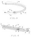
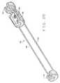
- FIG. 3is an illustration of the control cable shown in FIG. 1 ;
- FIG. 4is an illustration of the slide unit shown in FIG. 1 ;
- FIG. 5is a block diagram of one embodiment of an advancer control system
- FIG. 6is a schematic block diagram of the controller shown in FIG. 5 ;
- FIG. 7is a schematic block diagram of a joystick input device shown in FIG. 5 ;
- FIG. 8Ais an illustration of a magnetic navigation system control computer display at the start of a procedure
- FIG. 8Bis an illustration of a magnetic navigation system control computer display during a procedure
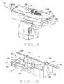
- FIG. 9is a perspective view of a patient on a bed, showing a drive unit of a second embodiment of an advancer system of the present invention.
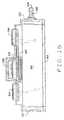
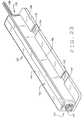
- FIG. 10is a perspective view of the drive unit shown in FIG. 9 ;
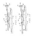
- FIG. 11is a perspective view of a drive unit of a third embodiment of an advancer system
- FIG. 12is a perspective view of a drive unit of a fourth embodiment of an advancer system
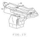
- FIG. 13is a perspective view of a drive unit of a fifth embodiment of an advancer system
- FIG. 14is a perspective view of a sixth embodiment of an advancer system drive unit constructed according to the principles of this invention.
- FIG. 16is a front elevation view of the drive unit of the sixth embodiment.
- FIG. 17is a left side elevation view of the drive unit of the sixth embodiment.
- FIG. 18is a right side elevation view of the drive unit of the sixth embodiment.
- FIG. 19is a cross-sectional view of the drive unit of the sixth embodiment, taken along the plane of line 19 - 19 in FIG. 15 ;
- FIG. 20is a cross-sectional view of the drive unit of the sixth embodiment, taken along the plane of line 20 - 20 in FIG. 15 ;
- FIG. 21is a diagram illustrating a method of advancing and retracting a catheter to reduce effects of static friction on the motion of a catheter, achievable with the methods and apparatus of the present invention
- FIG. 22is a perspective view of a slide unit constructed according to a seventh embodiment of the present invention, with the slide unit open;
- FIG. 23is a perspective view of the slide unit shown in FIG. 22 , with the advancer closed;
- FIG. 24is a perspective view of the left half of the housing of the slide unit shown in FIG. 22 ;
- FIG. 25is a front elevation view of the left half of the housing of the slide unit shown in FIG. 22 ;
- FIG. 26is a perspective view of a sliding support used in the slide unit shown in FIG. 22 ;
- FIG. 27is a frontal perspective view of a drive unit constructed according to an eighth embodiment of the present invention.
- FIG. 28is a rear perspective view of the drive unit shown in FIG. 27 ;
- FIG. 29is a frontal perspective view of the drive unit shown in FIG. 27 , with the sliding cover removed;
- FIG. 30is a bottom perspective view of the drive unit shown in FIG. 27 , with the bottom removed;
- FIG. 31is a side elevation sectional view of the bottom of the drive unit shown in FIG. 27 ;
- FIG. 32is a plan sectional view of the inside of the sliding cover of the drive unit shown in FIG. 27 ;
- FIG. 33is a side elevation sectional view of the base of the drive unit shown in FIG. 27 ;
- FIG. 34is a perspective view of the drive unit of the eighth preferred embodiment, shown in a mounting bracket.
- a first embodiment of an advancer system, or advancer, constructed according to the principles of this inventionis indicated generally as 20 in FIG. 1 .
- the advancer 20comprises a drive unit 28 that is connected to a slide unit 30 via a control cable 32 .
- the advancer drive unit 28is shown as it would be mounted on a patient table 22 for moving an elongate medical device in a patient lying on the table.
- the table 22has a support surface 24 and one or two side rails 26 .
- the medical devicemight be, for example, a catheter that is being advanced through the patient's vasculature, during a cardiac mapping procedure.
- the slide unit 30is shown resting on a leg of the patient.
- the advancer system 20also includes a control system having a controller or processor, and at least one operator input device, described in more detail below.
- the drive unit 28comprises a frame 34 having a bottom 36 , first and second ends 38 and 40 , and first and second sides 42 and 44 .
- a cover(not shown) may also be provided to enclose the drive unit.
- a lead screw 48extends longitudinally through the frame 34 , between the first and second ends 38 and 40 .
- a carrier 50is threadedly mounted on the lead screw 48 .
- the lead screw 48is driven by an electric motor 52 mounted on the first end 38 of the frame 34 , such that rotation of the lead screw causes the carrier 50 to move within the frame 34 .
- the drive unit 28includes a clip 54 for securing the drive unit to the patient table, for example, to side rail 26 .
- the control cable 32has a proximal end 56 and a distal end 58 .
- the control cable 32comprises a wire 60 enclosed in an outer sheath 62 .
- the proximal portion 64 of the wire 60is preferably relatively stiff, while the distal portion 66 of the wire is preferably more flexible.
- the proximal end of the wire 60is secured in a mounting 68 on the carrier 50
- the proximal end of the sheath 62is secured in a mounting 70 (shown in FIG. 2 ) on the second end 40 of the frame 34 .
- movement of the carrier 50 in the frame 34moves the wire 60 relative to its sheath 62 .
- the slide unit 30includes a tube 72 having proximal and distal ends 74 and 76 .
- the tube 72can be flexible so as to allow the tube to conform in shape to its supporting surface, e.g. a leg of the patient as shown in FIG. 1 .
- An attachment flap 78projects from the tube 72 , for securing the slide unit 30 .
- the distal end 76has a socket 80 for receiving a sheath (not shown) to enclose the distal end portion of the medical device being advanced.
- the socket 80includes a setscrew 82 for securing the sheath.
- a slider 84is slidably mounted in the tube 72 .
- the slider 84has a passage 90 therethrough for receiving an elongate medical device, such as a catheter, and a thumbscrew 86 for engaging a medical device in the passage.
- the tube 72has a longitudinally extending slot 88 through which the thumbscrew 86 extends.
- the proximal end of the tube 72connects to the distal end of the control cable 32 , and the distal end of the wire 60 is attached to the slider 84 .
- movement of the wire 60moves the slider 84 within the tube 72 .
- the advancer system 20also comprises a control system 98 .
- the control systemincludes a processor or controller 100 , configured to receive operator input from, for example, one or more joystick devices, such as a joystick device 102 located at the patient table 22 , or a joystick device 104 located in a remote control room.
- the controller 100interfaces with the drive unit 28 , selectively operating the motor 52 .
- the controller 100also interfaces with a control computer 106 , e.g. via an EIA RS-232 interface 108 or some other suitable interface.
- the computer 106is part of a magnetic navigation system (MNS) for controlling a magnet system for magnetically guiding a magnetically responsive medical device inside a patient's body.
- MNSmagnetic navigation system
- the operator joystick 102 or 104allows the operator to input information about the orientation and advancement/retraction of the medical device.
- the computer 106controls one or more magnets of the magnetic navigation system to apply a magnetic field to orient the medical device in a selected direction.
- the computer 106also can control the motor 52 , via the controller 100 , to advance or retract the magnetic medical device.
- the controller 100interfaces with the computer 106 for other purposes, e.g. to move the catheter based on physiological and/or imaging information.
- the drive unit 28is operated in a standalone manner, i.e. the controller 100 controls the drive unit 28 without interfacing with another computer such as computer 106 .
- the controller 100includes a power supply 110 , which is preferably an isolated medical grade supply, for supplying power to a driver circuit 112 for driving the motor 52 .
- the driver circuit 112is a bipolar chopper driver circuit.
- the controller 100also includes a microcontroller 114 that interfaces with the control computer 106 , input devices 102 and/or 104 , and the driver circuit 112 .
- the microcontroller 114may be controlled via software and/or hardware, and may be configured to provide the advancer 20 with additional capabilities not explicitly described herein but within the scope of the present invention.
- the controller 100also includes a “Motor Stop” button 116 for disconnecting the power supply 110 from the motor 52 , e.g. in an emergency.
- the “Motor Stop” button 116is hardwired to the power supply 110 for safety.
- the controller 100may also include a “Motor Status” indicator 118 , which might be, for example, a light emitting diode (LED) or other indicator to show when the advancer 20 is receiving power from the power supply 110 .
- the “Motor Status” indicator 118is lighted green when the power supply 110 is delivering power and is lighted yellow when power delivery is below an expected level.
- the button 116 and the indicator 118are located on the cover (not shown) of the drive unit 28 .
- the controller 100may also include a “Motor Home” button 120 which also may be located on the cover (not shown) of the drive unit 28 .
- the joystick devices 102 and/or 104have a stick with a motion-enable button 130 which the operator manipulates to operate the advancer 20 to advance and retract the medical device.
- a foot pedal or other devicecan be provided to facilitate the operator's use of the advancer.
- the joystick devicespreferably also include a “Motor Stop” button 134 and a “Motor Status” indicator 136 which function as described with respect to the “Motor Stop” button 116 and “Motor Status” indicator 118 (described above with respect to FIG. 6 ).
- the joystick devices 102 and 104include a “Make Input Active” button 138 , an “Active Input” indicator 140 , which may be, for example, an LED, and a “Set Reference Position” button 142 .
- the slide unit 30is placed upon a surface, for example the patient's leg.
- the flap 78aids in fixing the slide unit in place.
- a hemostasis valve from the protective sheath of the catheteris attached to the socket 80 and secured with thumbscrew 82 .
- the hemostasis valvedoes not move during use of the advancer 20 , and instead the catheter or other medical device advances and retracts relative to the sheath.
- the motor drive unit 28is preferably located outside of the sterile operating field so that it does not have to be sterilized and kept sterile, while the control cable 32 and slide unit 30 are located inside the sterile field, and are kept sterile.
- the slide unit 30is attached to a sterile drape on the leg of the patient via the attachment flap 78 with towel clips (not shown), or other suitable fasteners, to prevent injury in case of patient movement.
- the control cable 32is attached to the slide unit 30 to translate motion of the motor 52 to the slider 84 of the slide unit 30 . More specifically, and as shown in FIGS. 2 through 4 , the distal end of the outer sheath 62 of the control cable 32 is attached to a connector (not shown) on the proximal end 74 of the tube 72 , and the wire 60 is attached to the slider 84 .
- An elongate medical devicesuch as a catheter, is then attached to the slider 84 .
- a 7-French-size mapping catheter manufactured by Stereotaxis, Inc., of St. Louis, Mo.is placed in the slider 84 and secured with thumbscrew 86 .
- the slider 84can be attached to the catheter at any point along the catheter, depending on a desired location in the heart of the patient to be reached by the catheter. By loosening the attachment of the slider 84 to the catheter, the catheter position can be adjusted during the procedure, for example, to allow for manual navigation of the catheter. After catheter adjustment, the slider 84 is reattached to the catheter. Alternatively, after the catheter is freed from the slider 84 , the catheter can be quickly removed.
- the operatordepresses the “Motor Home” button 120 to place the motor 52 in a starting position. More specifically, the motor 52 is reversed until a proximal limit switch (not shown) on the lead screw 48 is activated. A fully retracted starting position of the motor 52 then is registered with the microcontroller 114 control software.
- the operatorselects a joystick device 102 or 104 as active by depressing the “Make Input Active” button 138 on the device.
- the controller 100recognizes commands from the selected device 102 or 104 and ignores commands from any other input device(s) 102 and 104 .
- the “Active Input” indicator 140 on the selected device 102 or 104is lighted green to indicate the selection. If the controller 100 is in an automated mapping mode as further described below, the “Active Input” indicator 140 is lighted yellow on each input device 102 , and depressing the “Make Input Active” button 138 on any device 102 or 104 has no effect on the advancer 20 .
- the operatorenters input via a remotely located input device 104 , or via an input device 102 at the table 22 as previously described.
- the operation of the joystickcauses the motor 52 to operate, which in turn causes the lead screw 48 to turn, which causes the carrier 50 to translate in the frame 34 .
- the translation of the carrier 50moves the wire 60 , which in turn moves the slider 84 within the tube 72 .
- Motion of the slider 84pushes and pulls the catheter secured in the slider 84 .
- the controller 100signals the motor 52 to advance or reverse in accordance with the joystick input.
- the speed of the motor 52is continuously variable and proportional to a distance of advancement or retraction of the joystick.
- the control cable 32translates motion of the motor 52 to the slider unit 30 . More specifically, as the motor 52 turns, the wire 60 moves relative to the outer sheath 62 . Thus the motion is translated through the control cable 32 , and the slider 84 can be alternately advanced and retracted relative to the tube 72 .
- the slide tube 72supports the catheter to prevent it from buckling as the slider 84 is advanced and retracted.
- the relatively stiff proximal segment 64resists buckling of the wire 60 during advancement when motion of the motor 52 is translated to the catheter.
- the flexible distal segment 66allows the control cable 32 to bend readily and allows the slide unit 30 to lie flat on the leg of the patient. The flexible segment 66 also compensates for movement by the patient.
- the operatorcan press the “Set Reference Position” button 142 , to save a current position of the motor 52 (for example, in the microcontroller 114 ).
- the operatorthus can use the saved motor 52 position as a reference point for navigation during a procedure.
- the current position of the motor 52also is displayed with other status information for the motor 52 as described below.
- the advancer 20can be adapted for use in automated cardiac mapping, in which case the controller 100 receives commands from the MNS control computer 106 to navigate the catheter during cardiac mapping.
- the MNS computer 106sends mapping commands to an active device 102 via controller 100 , and “Active Input” LED 140 is lighted yellow on each input device 102 and 104 .
- a second embodiment of an advancer constructed according to the principles of this inventionis indicated generally as 300 in FIG. 9 .
- the advancer 300comprises a drive unit 310 , shown as it would be mounted on a patient table 302 , for moving a medical device in a patient lying on the patient table.
- the medical devicemight be, for example, a catheter that is being advanced through a patient's vasculature, during a cardiac mapping procedure.
- the advancer 300is adapted for moving a medical device through a sheath 306 and into a patient on the table 302 .
- the advancer 300also includes a control system having a controller or processor, and at least one operator input, for example, as previously described with respect to FIGS. 5 through 8 .
- the drive unit 310comprises a frame 312 having a bottom 314 , first and second ends 316 and 318 , and first and second sides 320 and 322 .
- a cover(not shown) may also be provided to enclose the drive unit 310 .
- a lead screw 324extends longitudinally through the frame 312 , between the first and second ends 316 and 318 .
- a carrier 326is threadedly mounted on the lead screw 324 .
- the lead screw 324is driven by an electric motor 328 mounted on the first end 316 of the frame 312 , such that rotation of the lead screw causes the carrier 326 to move within the frame 312 .
- the drive unit 310is placed on the table 302 , e.g. between the legs of the patient.
- the drive unit 310is sufficiently heavy to remain stationary if the patient moves or when the drive unit 310 is exposed to magnetic forces from a magnetic navigation system such as the MNS described in connection with FIGS. 5 and 6 .
- the drive unitwould preferably be made non-magnetic.
- the drive unit 310rests on a sterile drape (not shown) and is placed in a sterile bag (not shown), and thus is reusable.
- the motor 328can be a stepper motor electrically connected to a controller such as the controller 100 (shown in FIGS. 5 and 6 ). In another embodiment the motor 328 is a servomotor.
- the drive unit 310may include one or more limit switches (not shown) under control of the controller to prevent over-travel, as described above in relation to the drive unit 28 (shown in FIG. 2 ).
- a catheter 330is attached to the carrier 326 , via a U-shaped bracket 332 (or any other suitable means).
- the proximal end of the sheath 334with a hemostasis valve 336 thereon, is secured on a fixture 338 on the second end 318 of the frame 312 .
- the catheter 330can be inserted into the bracket 332 at any point in its length.
- the cathetercan be removed from the bracket, for example, for manual advancement, and reinserted at a different point along its length.
- a third embodiment of an advancer drive unitis indicated generally as 400 in FIG. 11 .
- the drive unit 400comprises a base 402 , on which a shuttle 404 is slideably mounted.
- a catheter mover 406having a bracket 408 for engaging a catheter 420 is fixedly mounted on the shuttle 404 .
- a sheath mover 410having a bracket 412 for engaging a sheath 422 is slideably mounted on the shuttle 404 .
- a first motor 414moves the sheath mover 410 relative to the shuttle 404 .
- a second motor 416moves the shuttle 404 relative to the base 402 .
- a third motor 418causes the bracket 412 of the sheath mover to turn, causing the sheath 422 to turn to facilitate the advancement of the catheter 420 .
- the catheter and sheathcan be advanced and retracted together by movement of the shuttle 404 relative to the base 402 , or the sheath can be advanced or retracted relative to the catheter by movement of the sheath mover 410 relative to the shuttle 404 , or the catheter can be advanced or retracted relative to the sheath by a combination of movement of the shuttle 404 relative to the base 402 , and the sheath mover 410 relative to the shuttle.
- the catheter mover 406 and bracket 408could be configured with a motor that causes the bracket 408 , and catheter 420 , to rotate.
- either or both of the sheath and cathetercould be rotated relative to a patient.
- a fourth embodiment of an advancer drive unitis indicated generally as 450 in FIG. 12 .
- the drive unit 450comprises a base 452 , on which a shuttle 454 is slideably mounted.
- a catheter mover 456 having a bracket 458 for engaging the catheteris fixedly mounted on the shuttle 454 .
- a sheath mover 460 having a bracket 462 for engaging the sheathis slideably mounted on the shuttle 454 .
- a tube 470 for supporting the sheathis mounted to the base 452 and to a sheath insertion site on a patient.
- a first motor 464moves the sheath mover 460 relative to the shuttle 454 .
- a second motor 466moves the shuttle 454 relative to the base 452 .
- a third motor 468causes the bracket 462 of the sheath mover to turn, causing the sheath to turn to facilitate the advancement of the catheter.
- the catheter and sheathcan be advanced and retracted together by movement of the shuttle 454 relative to the base 452 , or the sheath can be advanced or retracted relative to the catheter by movement of the sheath mover 460 relative to the shuttle 454 , or the catheter can be advanced or retracted relative to the sheath by a combination of movement of the shuttle relative to the base, and the sheath mover relative to the shuttle.
- a fifth embodiment of an advancer drive unit constructed according to the principles of this inventionis indicated generally as 500 in FIG. 13 .
- the drive unit 500includes a lightweight, e.g. less than one-pound, motor 510 and is attached, for example, on the thigh of a patient lying on a table 512 .
- the motor 510preferably is sterilizable and disposable, thus allowing a catheter and sheath to be directly attached to the advancer drive unit 500 .
- the drive unit 500is controlled by a control system (not shown in FIG. 13 ), as previously described in connection with FIGS. 5 through 8 .
- a sixth embodiment of an advancer drive unitis indicated generally as 600 in FIGS. 14 through 20 .
- the drive unit 600comprises a generally hollow box-shaped housing 602 having a bottom 604 , a front 606 , a back 608 , left and right sides 610 and 612 , and a top 614 .
- a slot 616extends transversely across the top 614 .
- Opposed wheels 618 and 620protrude into the slot 616 to engage an elongate medical device, such as a catheter.
- the wheel 618is a driven wheel
- the wheel 620is an idler wheel.
- the wheel 618has two circumferentially extending rings on its surface, forming a circumferentially extending groove 622 between them for engaging an elongate medical device.
- the wheel 618is mounted on a shaft 624 , which is journaled in a vertically extending passage 626 .
- a bevel gear 628is mounted on the shaft 624 .
- a drive shaft 630having first and second ends 632 and 634 , is journaled in a horizontally extending passage 646 .
- the first end 632 of the drive shaft 630has a bevel gear 638 that engages the bevel gear 628 on the shaft 624 .
- the second end 634 of the drive shaft 630extends out the side 612 of the housing 604 and is connected to a drive motor (not shown).
- the wheel 620is mounted underneath a removable support 636 on the top 614 of the housing 602 .
- a screw 648rotatably mounts the wheel 620 to and underneath the support 636 .
- Screws 640secure the support 636 on the top 614 of the housing.
- the surface of the wheel 620is preferably contoured, with a recess 642 aligned with the groove 622 on the wheel 618 to firmly engage an elongate medical device between them.
- sliding covers 644on either side of the opposed wheels 618 and 620 , that can be slid to selectively extend over the slot 616 in the top 614 , to help retain the elongate medical device in the slot.
- the advancer drive unit 600is connected to a controlled motor, such as a stepper motor.
- a controlled motorsuch as a stepper motor.
- An elongate medical deviceis loaded into the drive unit by laying and pressing a length of the device into the slot 616 in the top 614 of the housing 602 , and between the opposed wheels 618 and 620 , until the device is engaged by the wheels between the groove 622 and the recess 642 .
- the drive shaft 630turns, turning bevel gear 634 , which in turn turns bevel gear 628 , turning shaft 624 , and thus wheel 618 , advancing or retracting the elongate medical device.
- the deviceWhen an elongate medical device is being advanced in a body, friction between the device and the tissues of the body may cause difficulty in advancing the device.
- the inventorshave discovered that by keeping the medical device in motion, static friction can be eliminated.
- the inventorshave found it more advantageous to advance the medical device and withdraw it slightly, rather than simply advance the medical device. More preferably, as shown in FIG. 21 , the device would be advanced a first distance, e.g. 0.003 inches, then retracted a second distance, e.g. 0.002 inches, advanced the second distance, e.g. 0.002 inches, and retracted the second distance 0.002 inches. Then the cycle is repeated, the device advancing a net 0.001 inches with each cycle.
- the advancer drive unitmay also be operated to successively move the medical device forward and back or to “stutter” to reduce static friction.
- the advancercan be controlled to begin advancing and retracting the device to reduce static friction.
- a seventh embodiment of a slide unitis indicated generally as 700 in FIGS. 22 and 23 . Portions of the slide unit 700 are shown in FIGS. 24 through 26 .
- the slide unit 700is adapted to be connected to a drive unit, such the drive unit 28 (shown in FIG. 2 ).
- the slide unit 700comprises an elongate housing 702 , formed in left and right halves 704 and 706 that are mounted on a bottom plate 708 .
- the housing 702comprises a proximal end 710 and a distal end 712 .
- the bottom 708has dovetail cutouts 714 which receive dovetail projections 716 on the bottoms of the left and right halves 704 and 706 .
- a slide 722can reciprocate.
- the slide 722has a latch 724 that can engage an elongate medical device such as a catheter.
- the slide 722also engages a wire 726 , for example, from a control cable connected to the drive unit 28 , described above.
- a slidable support 728is also positioned in the channel 720 .
- the slidable supportcomprises two rods 730 and 732 with a proximal support 734 and a distal support 736 .
- the proximal and distal supports 734 and 736engage and support an elongate medical device extending through the slide unit 700 .
- the slide 722is advanced within the channel 720 until it engages the distal support 736 , and then the slide 722 and the distal support advance together. Similarly, the slide 722 retracts until in engages the proximal support 734 , and the slide and the proximal support retract together.
- the slide unit 700has an attachment 740 for a sheath at the distal end 712 of the housing 702 . There an attachment at the proximal end 710 for the outer sheath 62 of the control cable.
- the advancer 700is opened by sliding the right half 706 away from the left half, and an elongate medical device such as a catheter is installed therein.
- the catheteris installed in the slide 722 , and the latch 724 closed to secure the catheter.
- the catheteris engaged in the supports 734 and 736 , and the two halves of the housing are slid together.
- the drive unit 28is used to move the wire 726 , and thereby move the slider 722 , which causes the catheter to move inwardly and outwardly.
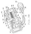
- FIGS. 27 through 33An eighth embodiment of a drive unit constructed according to the principle of this invention is indicated generally as 800 in FIGS. 27 through 33 .
- the drive unit 800preferably is small 2.6 inches long, 1.1 inches wide (the longitudinal direction), and 1 inch high sterile and disposable. It can be used close to an insertion site on a patient.
- the drive unit 800generally is preferably fabricated of non-magnetic materials, and more preferably of non-metallic materials, or at least substantially of non-magnetic materials.
- the exterioris made from ABS or other suitable material, and the interior components are Delrin or other suitable polymer.
- the drive unitis at least primarily non-magnetic i.e.
- the drive unitis preferably also at least primarily non-metallic i.e. it is sufficiently non-metallic that it will not interfere with the operation of a magnetic localization system for magnetically localizing the position of the distal end of the elongate medical device in the operating region.
- the deviceis sufficiently non-magnetic and non-metallic that it can be left in place during MR imaging.
- the drive unit 800comprises a front 804 , a back 806 , a right side 808 and a left side 810 .
- a generally hollow curved housing 812comprises a base 814 and a sliding cover 816 resting on a bottom 818 .
- the base 814is affixed to the bottom 818 by a pair of opposed pins (not shown) through aligned holes 802 in the base and bottom.
- the pinsare preferably a non-magnetic, non-corrosive material such as stainless steel.
- the sliding cover 816is movably attached to the bottom 818 by a pair of opposed pins (not shown) through a pair of holes 828 in the cover (shown in FIG. 30 ) and a pair of horizontal slots 872 in the bottom 818 (shown in FIG. 31 ).
- the cover 816can be slid horizontally away from and toward the base 814 as limited by the slots 872 , as further described below.
- a slot 820 in the base 814extends longitudinally through the drive unit 800 and is configured to hold an elongate medical device such as a catheter.
- a hemostasis valve adapter 822is mounted in a front end 824 of the slot 820 .
- the cathetercan be extended through the adapter 822 into an attached sheath or introducer (not shown in FIGS. 27 through 33 ) having a distal end inserted in a patient.
- the adapter 822preferably is flexible and has an interior surface 826 of Teflon® or other material having a coefficient of friction sufficiently low to aid in preventing buckling of the catheter as it moves through the drive unit 800 .
- the slot 820is covered by the sliding cover 816 when the cover 816 is closed as further described below.
- Opposed wheels 832 and 834protrude into the slot 820 to engage the catheter.
- wheel 832is a driven wheel
- wheel 834is an idler wheel.
- the wheels 832 and 834may be fabricated in various ways depending, for example, on the type, material and/or flexibility of the medical device to be driven through the drive unit.
- the wheelsmay be fabricated of a hard material that can flow in an injection mold sufficiently to form small teeth 836 that can grip a catheter as it is driven past the wheels.
- “Small” teethinclude, for example, teeth having a height of 0.01 inch.
- the wheels 832 and 834can be fabricated of a soft material, for example, rubber, such that the wheels would contour and deform slightly so as not to crush a catheter being driven by the wheels.
- one or both of the wheels 832 and 834can be circumferentially grooved, like the wheel 618 of the drive unit 600 (shown in FIGS. 14 through 20 ), for engaging an elongate medical device.
- the driven wheel 832is mounted on a shaft 838 .
- the shaft 838is mounted vertically in and between a base socket 840 (shown in FIG. 33 ) and a bottom socket 842 (shown in FIG. 31 ).
- a worm gear 844is mounted on the shaft 838 .
- a rigid drive shaft 848is rotatably mounted longitudinally in the base 814 and extends through the back 806 of the drive unit 800 .
- the drive shaft 848has a worm 850 that engages the worm gear 844 on the shaft 838 .
- a flexible drive shaft 846is connected to the rigid drive shaft 848 via a connector 884 , and to a drive motor 886 via a connector 888 .
- the drive motor 886is a bi-directional controlled motor, for example, a stepper motor, that preferably can be controlled remotely as previously described in connection with the drive unit 28 (shown in FIGS. 1 through 5 ). In other embodiments, the motor 886 can be a servomotor.
- the flexible drive shaft 846includes a 3/16-inch-diameter flexible coil 890 , preferably fabricated of non-magnetic stainless steel and covered by a flexible clear plastic tubing 892 .
- the coil 890is rotatable by the motor 886 in forward and reverse directions to provide bi-directional movement of the drive wheel 832 .
- the flexible drive shaft 846preferably is sterile for use within a sterile operating area.
- the drive shaft 846also preferably is sufficiently long (for example, approximately four feet long) to allow it to be driven by the motor 886 while the motor remains outside the sterile area.
- the motor 886is also sterile, is used within the sterile operating area, and is disposed of after completion of the operating procedure.
- the idler wheel 834is mounted on a shaft 852 snap-fitted into and extending vertically from a slot (not shown) in a floor 854 of the base 814 .
- An upper end 856 of the shaft 852fits in a groove 858 (shown in FIG. 32 ) extending transversely along an inner surface 860 of the sliding cover 816 .
- a spring 880is stretched, beneath the base floor 854 , between an edge 882 of the sliding cover 816 and a vertical support 894 of the base 814 .
- the springis a non-magnetic, non-corrosive material such as stainless steel. The spring force thus pulls the sliding cover 816 horizontally toward the idler wheel shaft 852 .
- the force of the spring 880causes an end 896 of the groove 858 to press against the shaft upper end 856 .
- the idler wheel 834thus is pressed against a medical device engaged between the wheel 834 and the driver wheel 832 .
- a generally U-shaped lever arm or handle 864is used to open the sliding cover 816 relative to the base 814 .
- Two ends 866 of the handleare rotatably mounted over two sides 868 of the sliding cover 816 on a pair of opposed pivots 870 .
- the pivots 870further extend toward each other through two cams 874 .
- each of the camsis limited in its range of motion by an upper shelf 898 in the base 814 .
- the cover 816is biased by the spring 880 in a closed position against the shaft upper end 856 , the cams are biased in an upright position as shown in FIG. 30 , and the handle 864 is biased to lie flush against the cover 816 .
- a userrotates the handle 864 away from the slot 820 in the base 814 .
- the cams 874also rotate to lie flat against the bottom 818 .
- the pins through the holes 828 and bottom slots 872move horizontally in the slots 872 away from the slot 820 in the base 814 .
- the sliding cover 816thus is opened sufficiently to uncover the slot 820 in the base 814 .
- the groove 858 in the underside of the cover 816allows the cover 816 to be slid open, and subsequently closed, without disturbing the upper end 856 of the idle wheel shaft 852 .
- the cams 874are positioned so as to lock the cover 816 in the open position.
- An elongate medical deviceis loaded into the drive unit 800 by laying and pressing a length of the device into the slot 820 between the opposed wheels 832 and 834 , until the device is engaged by the wheels, for example, between two grooves in wheels 832 and 834 as previously described.
- the userthen presses the handle 864 toward the slot 820 , thereby causing the cams to return to the upright position.
- the sliding coveris pulled by the spring 880 into a closed position over the elongate medical device.
- the rigid drive shaft 848turns, turning the worm 850 , which in turn drives the worm gear 844 , turning the drive wheel shaft 838 and thus the drive wheel 832 .
- the medical deviceis advanced and/or retracted through the adapter 822 and attached sheath.
- the drive unit 800is shown in FIG. 34 , as it would be mounted on a support bracket 900 .
- the support bracket 900comprises a flexible, generally U-shaped base 902 , having a bottom surface adapted to be secured on the patient.
- the bottom surfacemay be provided with a double stick adhesive, with a protective sheet, so that the support bracket 900 can be attached to patient, typically on the patients thigh, adjacent the femoral artery.
- the strutshave slots 908 and 910 , therein.
- the slots 908 and 910are mirror images of one another, comprising a vertically extending portion 912 , a horizontally extending portion 914 , and a circular portion 916 .
- a bed 918is mounted between the struts 904 and 906 , with thumb screws 920 extending through the slot and into the bed. Each thumb screw can be tightened to engage the margins of the strut surrounding the slot to fix the end of the bed.
- the drive unit 800can be secured to the bed, for example with double-stick adhesive provided on the surface of the bed, and covered with a removable protective sheet.
- the support bracketallows the drive unit 800 to be oriented at various angles to accommodate the catheter orientation at the entry point to the body, (typically at the femoral artery).
- rotary drive units 600 and 800can provide a driving force to a medical device while preventing slippage of the device during advancement or retraction.
- a drive unit utilizing a slidere.g. the drive unit 28 in combination with slider 30 or 700 , tends to apply less pressure against a device than would a rotary drive unit.
- two drive unitscould be controlled together by an advancer control system and/or magnetic navigation system to move one elongate device relative to another elongate device in a patient.
- a cathetercould be advanced and retracted using a rotary drive unit, while a sheath holding the catheter could be advanced and retracted using a drive unit/control cable/slider combination.
- Other embodiments of courseare possible, in which drive units, control cables and/or sliders are utilized and/or combined to advance and/or retract on or more elongate medical devices.
- a drive unitfor example, may be selected for attachment to a patient table or to a body part of the patient.
- a non-magnetic drive unitcan be used within the operating site without causing magnetic interference.
- joystick devicesare provided at the patient table and in a control room, an operating physician can use the system at the patient table during procedure setup and then can perform the procedure from the control room outside an imaging x-ray field. Thus the physician can avoid repeated x-ray exposures.
Landscapes
- Health & Medical Sciences (AREA)
- Life Sciences & Earth Sciences (AREA)
- Biophysics (AREA)
- Pulmonology (AREA)
- Engineering & Computer Science (AREA)
- Anesthesiology (AREA)
- Biomedical Technology (AREA)
- Heart & Thoracic Surgery (AREA)
- Hematology (AREA)
- Animal Behavior & Ethology (AREA)
- General Health & Medical Sciences (AREA)
- Public Health (AREA)
- Veterinary Medicine (AREA)
- Media Introduction/Drainage Providing Device (AREA)
Abstract
Description
Claims (20)
Priority Applications (1)
| Application Number | Priority Date | Filing Date | Title |
|---|---|---|---|
| US11/770,639US7766856B2 (en) | 2001-05-06 | 2007-06-28 | System and methods for advancing a catheter |
Applications Claiming Priority (3)
| Application Number | Priority Date | Filing Date | Title |
|---|---|---|---|
| US28887901P | 2001-05-06 | 2001-05-06 | |
| US10/138,710US7276044B2 (en) | 2001-05-06 | 2002-05-03 | System and methods for advancing a catheter |
| US11/770,639US7766856B2 (en) | 2001-05-06 | 2007-06-28 | System and methods for advancing a catheter |
Related Parent Applications (1)
| Application Number | Title | Priority Date | Filing Date |
|---|---|---|---|
| US10/138,710Continuation-In-PartUS7276044B2 (en) | 2001-05-06 | 2002-05-03 | System and methods for advancing a catheter |
Publications (2)
| Publication Number | Publication Date |
|---|---|
| US20080045892A1 US20080045892A1 (en) | 2008-02-21 |
| US7766856B2true US7766856B2 (en) | 2010-08-03 |
Family
ID=26836440
Family Applications (1)
| Application Number | Title | Priority Date | Filing Date |
|---|---|---|---|
| US11/770,639Expired - LifetimeUS7766856B2 (en) | 2001-05-06 | 2007-06-28 | System and methods for advancing a catheter |
Country Status (1)
| Country | Link |
|---|---|
| US (1) | US7766856B2 (en) |
Cited By (68)
| Publication number | Priority date | Publication date | Assignee | Title |
|---|---|---|---|---|
| US20100298845A1 (en)* | 2009-05-25 | 2010-11-25 | Kidd Brian L | Remote manipulator device |
| US7961926B2 (en) | 2005-02-07 | 2011-06-14 | Stereotaxis, Inc. | Registration of three-dimensional image data to 2D-image-derived data |
| US20120016346A1 (en)* | 2010-04-08 | 2012-01-19 | BiO2 Medical, Inc. | Catheter hub |
| US20120035596A1 (en)* | 2010-08-04 | 2012-02-09 | Tegg Troy T | Disposable Drive Interface for Longitudinal Movement of an Elongate Medical Device |
| US8114032B2 (en)* | 2001-05-06 | 2012-02-14 | Stereotaxis, Inc. | Systems and methods for medical device advancement and rotation |
| US8308628B2 (en) | 2009-11-02 | 2012-11-13 | Pulse Therapeutics, Inc. | Magnetic-based systems for treating occluded vessels |
| US8369934B2 (en) | 2004-12-20 | 2013-02-05 | Stereotaxis, Inc. | Contact over-torque with three-dimensional anatomical data |
| US20140276389A1 (en)* | 2013-03-13 | 2014-09-18 | Sean Walker | Selective grip device for drive mechanism |
| US20150273686A1 (en)* | 2013-03-15 | 2015-10-01 | Corindus, Inc. | Systen and method for controlling a position of an articulated robotic arm |
| US20160338785A1 (en)* | 2013-03-15 | 2016-11-24 | Hansen Medical, Inc. | Active drive mechanism with finite range of motion |
| US9554930B2 (en) | 2014-04-25 | 2017-01-31 | Cook Medical Technologies Llc | Powered medical device deployment system |
| US9883878B2 (en) | 2012-05-15 | 2018-02-06 | Pulse Therapeutics, Inc. | Magnetic-based systems and methods for manipulation of magnetic particles |
| US10213264B2 (en) | 2013-03-14 | 2019-02-26 | Auris Health, Inc. | Catheter tension sensing |
| US10219874B2 (en) | 2013-10-24 | 2019-03-05 | Auris Health, Inc. | Instrument device manipulator with tension sensing apparatus |
| US10398518B2 (en) | 2014-07-01 | 2019-09-03 | Auris Health, Inc. | Articulating flexible endoscopic tool with roll capabilities |
| US10454347B2 (en) | 2016-04-29 | 2019-10-22 | Auris Health, Inc. | Compact height torque sensing articulation axis assembly |
| US10470830B2 (en) | 2017-12-11 | 2019-11-12 | Auris Health, Inc. | Systems and methods for instrument based insertion architectures |
| US10478595B2 (en) | 2013-03-07 | 2019-11-19 | Auris Health, Inc. | Infinitely rotatable tool with finite rotating drive shafts |
| US10493239B2 (en) | 2013-03-14 | 2019-12-03 | Auris Health, Inc. | Torque-based catheter articulation |
| US10524867B2 (en) | 2013-03-15 | 2020-01-07 | Auris Health, Inc. | Active drive mechanism for simultaneous rotation and translation |
| US10537713B2 (en) | 2009-05-25 | 2020-01-21 | Stereotaxis, Inc. | Remote manipulator device |
| US10543048B2 (en) | 2016-12-28 | 2020-01-28 | Auris Health, Inc. | Flexible instrument insertion using an adaptive insertion force threshold |
| US10543047B2 (en) | 2013-03-15 | 2020-01-28 | Auris Health, Inc. | Remote catheter manipulator |
| US10556092B2 (en) | 2013-03-14 | 2020-02-11 | Auris Health, Inc. | Active drives for robotic catheter manipulators |
| US10569052B2 (en) | 2014-05-15 | 2020-02-25 | Auris Health, Inc. | Anti-buckling mechanisms for catheters |
| US10631949B2 (en) | 2015-09-09 | 2020-04-28 | Auris Health, Inc. | Instrument device manipulator with back-mounted tool attachment mechanism |
| US10682189B2 (en) | 2016-08-31 | 2020-06-16 | Auris Health, Inc. | Length conservative surgical instrument |
| US10687903B2 (en) | 2013-03-14 | 2020-06-23 | Auris Health, Inc. | Active drive for robotic catheter manipulators |
| US10695536B2 (en) | 2001-02-15 | 2020-06-30 | Auris Health, Inc. | Catheter driver system |
| US10820954B2 (en) | 2018-06-27 | 2020-11-03 | Auris Health, Inc. | Alignment and attachment systems for medical instruments |
| US10820952B2 (en) | 2013-03-15 | 2020-11-03 | Auris Heath, Inc. | Rotational support for an elongate member |
| US10820947B2 (en) | 2018-09-28 | 2020-11-03 | Auris Health, Inc. | Devices, systems, and methods for manually and robotically driving medical instruments |
| US10864629B2 (en) | 2013-03-15 | 2020-12-15 | Corindus, Inc. | System and method for controlling a position of an articulated robotic arm |
| US10888386B2 (en) | 2018-01-17 | 2021-01-12 | Auris Health, Inc. | Surgical robotics systems with improved robotic arms |
| US11026758B2 (en) | 2017-06-28 | 2021-06-08 | Auris Health, Inc. | Medical robotics systems implementing axis constraints during actuation of one or more motorized joints |
| US11147637B2 (en) | 2012-05-25 | 2021-10-19 | Auris Health, Inc. | Low friction instrument driver interface for robotic systems |
| US11213363B2 (en) | 2013-03-14 | 2022-01-04 | Auris Health, Inc. | Catheter tension sensing |
| US11241559B2 (en) | 2016-08-29 | 2022-02-08 | Auris Health, Inc. | Active drive for guidewire manipulation |
| US11278703B2 (en) | 2014-04-21 | 2022-03-22 | Auris Health, Inc. | Devices, systems, and methods for controlling active drive systems |
| US11382650B2 (en) | 2015-10-30 | 2022-07-12 | Auris Health, Inc. | Object capture with a basket |
| US11439419B2 (en) | 2019-12-31 | 2022-09-13 | Auris Health, Inc. | Advanced basket drive mode |
| US11510736B2 (en) | 2017-12-14 | 2022-11-29 | Auris Health, Inc. | System and method for estimating instrument location |
| US11534249B2 (en) | 2015-10-30 | 2022-12-27 | Auris Health, Inc. | Process for percutaneous operations |
| US11571229B2 (en) | 2015-10-30 | 2023-02-07 | Auris Health, Inc. | Basket apparatus |
| US11638618B2 (en) | 2019-03-22 | 2023-05-02 | Auris Health, Inc. | Systems and methods for aligning inputs on medical instruments |
| US11737845B2 (en) | 2019-09-30 | 2023-08-29 | Auris Inc. | Medical instrument with a capstan |
| US11744659B2 (en) | 2019-07-19 | 2023-09-05 | Corindus, Inc. | Load sensing of elongated medical device in robotic actuation |
| US11771309B2 (en) | 2016-12-28 | 2023-10-03 | Auris Health, Inc. | Detecting endolumenal buckling of flexible instruments |
| US11839440B2 (en) | 2021-07-30 | 2023-12-12 | Corindus, Inc. | Attachment for robotic medical system |
| US11844732B2 (en) | 2021-07-30 | 2023-12-19 | Corindus, Inc. | Support for securing a robotic system to a patient table |
| US11896330B2 (en) | 2019-08-15 | 2024-02-13 | Auris Health, Inc. | Robotic medical system having multiple medical instruments |
| US11896325B2 (en) | 2019-07-15 | 2024-02-13 | Corindus, Inc. | Systems and methods for a control station for robotic interventional procedures using a plurality of elongated medical devices |
| US11903669B2 (en) | 2021-07-30 | 2024-02-20 | Corindus, Inc | Sterile drape for robotic drive |
| US11906009B2 (en) | 2021-07-30 | 2024-02-20 | Corindus, Inc. | Rotational joint assembly for robotic medical system |
| US11918315B2 (en) | 2018-05-03 | 2024-03-05 | Pulse Therapeutics, Inc. | Determination of structure and traversal of occlusions using magnetic particles |
| US11950872B2 (en) | 2019-12-31 | 2024-04-09 | Auris Health, Inc. | Dynamic pulley system |
| US12035989B2 (en) | 2021-08-02 | 2024-07-16 | Corindus, Inc. | Systems and methods for a control station for robotic interventional procedures using a plurality of elongated medical devices |
| US12171443B1 (en) | 2021-03-09 | 2024-12-24 | Pulse Therapeutics, Inc. | Magnetically controlled flow generation |
| US12245882B2 (en) | 2020-01-07 | 2025-03-11 | Cleerly, Inc. | Systems, methods, and devices for medical image analysis, diagnosis, risk stratification, decision making and/or disease tracking |
| US12257086B2 (en) | 2022-11-11 | 2025-03-25 | Siemens Healthineers Endovascular Robotics, Inc. | Arrangement for securing a robotic system to a patient table |
| US12283046B2 (en) | 2020-01-07 | 2025-04-22 | Cleerly, Inc. | Systems, methods, and devices for medical image analysis, diagnosis, risk stratification, decision making and/or disease tracking |
| US12299885B2 (en) | 2022-03-10 | 2025-05-13 | Cleerly, Inc. | Systems, devices, and methods for non-invasive image-based plaque analysis and risk determination |
| US12318161B2 (en) | 2021-10-05 | 2025-06-03 | Siemens Healthineers Endovascular Robotics, Inc. | Robotic actuation of elongated medical devices |
| US12324695B2 (en) | 2020-01-07 | 2025-06-10 | Cleerly, Inc. | Systems, methods, and devices for medical image analysis, diagnosis, risk stratification, decision making and/or disease tracking |
| US12324696B2 (en) | 2022-03-10 | 2025-06-10 | Cleerly, Inc. | Systems, devices, and methods for non-invasive image-based plaque analysis and risk determination |
| US12380560B2 (en) | 2022-03-10 | 2025-08-05 | Cleerly, Inc. | Systems, methods, and devices for image-based plaque analysis and risk determination |
| US12419501B2 (en) | 2019-07-15 | 2025-09-23 | Siemens Healthineers Endovascular Robotics, Inc. | Systems, apparatus and methods for robotic interventional procedures using a plurality of elongated medical devices |
| US12440180B2 (en) | 2024-02-29 | 2025-10-14 | Cleerly, Inc. | Systems, devices, and methods for non-invasive image-based plaque analysis and risk determination |
Families Citing this family (40)
| Publication number | Priority date | Publication date | Assignee | Title |
|---|---|---|---|---|
| US20040030244A1 (en)* | 1999-08-06 | 2004-02-12 | Garibaldi Jeffrey M. | Method and apparatus for magnetically controlling catheters in body lumens and cavities |
| US6902528B1 (en)* | 1999-04-14 | 2005-06-07 | Stereotaxis, Inc. | Method and apparatus for magnetically controlling endoscopes in body lumens and cavities |
| US6940379B2 (en)* | 2000-04-11 | 2005-09-06 | Stereotaxis, Inc. | Magnets with varying magnetization direction and method of making such magnets |
| US7530948B2 (en)* | 2005-02-28 | 2009-05-12 | University Of Washington | Tethered capsule endoscope for Barrett's Esophagus screening |
| US9314222B2 (en)* | 2005-07-07 | 2016-04-19 | Stereotaxis, Inc. | Operation of a remote medical navigation system using ultrasound image |
| EP1907041B1 (en)* | 2005-07-11 | 2019-02-20 | Catheter Precision, Inc. | Remotely controlled catheter insertion system |
| US7495537B2 (en) | 2005-08-10 | 2009-02-24 | Stereotaxis, Inc. | Method and apparatus for dynamic magnetic field control using multiple magnets |
| US20070161882A1 (en)* | 2006-01-06 | 2007-07-12 | Carlo Pappone | Electrophysiology catheter and system for gentle and firm wall contact |
| US20080114335A1 (en)* | 2006-08-23 | 2008-05-15 | William Flickinger | Medical Device Guide |
| US7567233B2 (en)* | 2006-09-06 | 2009-07-28 | Stereotaxis, Inc. | Global input device for multiple computer-controlled medical systems |
| US8024024B2 (en)* | 2007-06-27 | 2011-09-20 | Stereotaxis, Inc. | Remote control of medical devices using real time location data |
| US20090105579A1 (en)* | 2007-10-19 | 2009-04-23 | Garibaldi Jeffrey M | Method and apparatus for remotely controlled navigation using diagnostically enhanced intra-operative three-dimensional image data |
| US8231618B2 (en) | 2007-11-05 | 2012-07-31 | Stereotaxis, Inc. | Magnetically guided energy delivery apparatus |
| US20090131798A1 (en)* | 2007-11-19 | 2009-05-21 | Minar Christopher D | Method and apparatus for intravascular imaging and occlusion crossing |
| US20090131927A1 (en)* | 2007-11-20 | 2009-05-21 | Nathan Kastelein | Method and apparatus for remote detection of rf ablation |
| WO2009092059A2 (en) | 2008-01-16 | 2009-07-23 | Catheter Robotics, Inc. | Remotely controlled catheter insertion system |
| JP5322153B2 (en)* | 2008-03-25 | 2013-10-23 | Ntn株式会社 | Drive device for medical linear body |
| US20100069733A1 (en)* | 2008-09-05 | 2010-03-18 | Nathan Kastelein | Electrophysiology catheter with electrode loop |
| US20120203168A1 (en)* | 2009-10-14 | 2012-08-09 | Hideo Fujimoto | Insertion device, training device, and recording system |
| EP3653151A1 (en) | 2011-10-17 | 2020-05-20 | Avinger, Inc. | Atherectomy catheters and non-contact actuation mechanism for catheters |
| US9694158B2 (en)* | 2011-10-21 | 2017-07-04 | Ahmad Mohamad Slim | Torque for incrementally advancing a catheter during right heart catheterization |
| US9533121B2 (en) | 2013-02-26 | 2017-01-03 | Catheter Precision, Inc. | Components and methods for accommodating guidewire catheters on a catheter controller system |
| US9724493B2 (en) | 2013-08-27 | 2017-08-08 | Catheter Precision, Inc. | Components and methods for balancing a catheter controller system with a counterweight |
| US9993614B2 (en) | 2013-08-27 | 2018-06-12 | Catheter Precision, Inc. | Components for multiple axis control of a catheter in a catheter positioning system |
| US9750577B2 (en) | 2013-09-06 | 2017-09-05 | Catheter Precision, Inc. | Single hand operated remote controller for remote catheter positioning system |
| US9999751B2 (en) | 2013-09-06 | 2018-06-19 | Catheter Precision, Inc. | Adjustable nose cone for a catheter positioning system |
| US9700698B2 (en) | 2013-09-27 | 2017-07-11 | Catheter Precision, Inc. | Components and methods for a catheter positioning system with a spreader and track |
| US9795764B2 (en) | 2013-09-27 | 2017-10-24 | Catheter Precision, Inc. | Remote catheter positioning system with hoop drive assembly |
| EP3437540B1 (en)* | 2016-03-31 | 2021-11-03 | Keio University | Endoscope holder with gripping members and with elastic members |
| WO2017169279A1 (en)* | 2016-03-31 | 2017-10-05 | 学校法人慶應義塾 | Endoscope holder |
| US10646689B2 (en) | 2016-07-29 | 2020-05-12 | Cephea Valve Technologies, Inc. | Mechanical interlock for catheters |
| US11109967B2 (en)* | 2016-08-29 | 2021-09-07 | Cephea Valve Technologies, Inc. | Systems and methods for loading and deploying an intravascular device |
| CN116271427A (en)* | 2017-03-06 | 2023-06-23 | 科林达斯公司 | Replacement of percutaneous devices |
| US11918761B2 (en) | 2018-09-14 | 2024-03-05 | Infraredx, Inc. | Intravascular imaging catheter system with force error detection and automatic remediation via pullback and rotation for translating and rotating a torque cable in a catheter |
| US12186188B2 (en) | 2019-05-01 | 2025-01-07 | Twelve, Inc. | Support devices for transcatheter delivery system handles |
| CN110339457B (en)* | 2019-08-23 | 2023-09-22 | 南通市第一人民医院 | Pusher for cardiovascular and thoracic vascular surgical intubation and use method thereof |
| US11464945B1 (en)* | 2020-07-07 | 2022-10-11 | Willie Henderson | Catheter canal |
| CN112704569B (en)* | 2020-12-23 | 2022-03-01 | 华中科技大学同济医学院附属协和医院 | Endoscopy operation simulation hand |
| JP7540118B6 (en)* | 2021-07-05 | 2024-09-12 | 深▲せん▼愛博合創医療机器人有限公司 | Interventional Surgery Robot Slave Device |
| EP4514261A1 (en)* | 2022-05-25 | 2025-03-05 | Boston Scientific Scimed, Inc. | Attachment mechanism for using an endoscope with a surgical robot |
Citations (100)
| Publication number | Priority date | Publication date | Assignee | Title |
|---|---|---|---|---|
| US3835854A (en) | 1970-02-27 | 1974-09-17 | Jewett Ashley Holding Corp | Catheter advancing device with nip rollers |
| US3838688A (en) | 1971-12-28 | 1974-10-01 | Int Paper Co | Catheter advances with clutch |
| US4401433A (en) | 1980-06-13 | 1983-08-30 | Luther Ronald B | Apparatus for advancing oversized catheter through cannula, and the like |
| US4564014A (en) | 1980-01-30 | 1986-01-14 | Thomas J. Fogarty | Variable length dilatation catheter apparatus and method |
| US4679557A (en)* | 1984-09-10 | 1987-07-14 | E. R. Squibb & Sons, Inc. | Electrodynamic transluminal angioplasty system |
| US4753248A (en) | 1987-06-24 | 1988-06-28 | Duke University | Probe translation system for use in hyperthermia treatment |
| US4795434A (en) | 1987-09-10 | 1989-01-03 | C. R. Bard, Inc. | Apparatus for positioning a sensor in vivo |
| US4856354A (en) | 1988-03-07 | 1989-08-15 | Combustion Engineering, Inc. | Inspection probe manipulator |
| US5256150A (en) | 1991-12-13 | 1993-10-26 | Endovascular Technologies, Inc. | Large-diameter expandable sheath and method |
| US5312361A (en) | 1991-09-13 | 1994-05-17 | Zadini Filiberto P | Automatic cannulation device |
| US5346498A (en) | 1991-11-06 | 1994-09-13 | Imagyn Medical, Inc. | Controller for manipulation of instruments within a catheter |
| US5361768A (en) | 1992-06-30 | 1994-11-08 | Cardiovascular Imaging Systems, Inc. | Automated longitudinal position translator for ultrasonic imaging probes, and methods of using same |
| US5389100A (en) | 1991-11-06 | 1995-02-14 | Imagyn Medical, Inc. | Controller for manipulation of instruments within a catheter |
| US5486161A (en) | 1993-02-02 | 1996-01-23 | Zomed International | Medical probe device and method |
| US5531713A (en) | 1991-10-31 | 1996-07-02 | Industria Prodotti Medicinali I.Pm. S.R.L. | Needle catheter with safety device |
| US5586968A (en) | 1992-12-15 | 1996-12-24 | Gruendl; Andreas | Method and apparatus for moving an endoscope along a canal-shaped cavity |
| US5654864A (en) | 1994-07-25 | 1997-08-05 | University Of Virginia Patent Foundation | Control method for magnetic stereotaxis system |
| US5690645A (en) | 1995-06-28 | 1997-11-25 | Cordis Corporation | Device for moving a catheter in a controlled manner |
| US5769086A (en)* | 1995-12-06 | 1998-06-23 | Biopsys Medical, Inc. | Control system and method for automated biopsy device |
| US5810835A (en) | 1994-12-28 | 1998-09-22 | Abbott Laboratories | Catheter insertion device with valve |
| US5827313A (en) | 1996-09-27 | 1998-10-27 | Boston Scientific Corporation | Device for controlled longitudinal movement of an operative element within a catheter sheath and method |
| US5931818A (en) | 1997-08-29 | 1999-08-03 | Stereotaxis, Inc. | Method of and apparatus for intraparenchymal positioning of medical devices |
| US5957941A (en) | 1996-09-27 | 1999-09-28 | Boston Scientific Corporation | Catheter system and drive assembly thereof |
| US6004271A (en) | 1998-05-07 | 1999-12-21 | Boston Scientific Corporation | Combined motor drive and automated longitudinal position translator for ultrasonic imaging system |
| US6014580A (en) | 1997-11-12 | 2000-01-11 | Stereotaxis, Inc. | Device and method for specifying magnetic field for surgical applications |
| US6128174A (en) | 1997-08-29 | 2000-10-03 | Stereotaxis, Inc. | Method and apparatus for rapidly changing a magnetic field produced by electromagnets |
| US6148823A (en) | 1999-03-17 | 2000-11-21 | Stereotaxis, Inc. | Method of and system for controlling magnetic elements in the body using a gapped toroid magnet |
| US6152933A (en) | 1997-11-12 | 2000-11-28 | Stereotaxis, Inc. | Intracranial bolt and method of placing and using an intracranial bolt to position a medical device |
| US6157853A (en) | 1997-11-12 | 2000-12-05 | Stereotaxis, Inc. | Method and apparatus using shaped field of repositionable magnet to guide implant |
| US6171234B1 (en)* | 1998-09-25 | 2001-01-09 | Scimed Life Systems, Inc. | Imaging gore loading tool |
| US6212419B1 (en) | 1997-11-12 | 2001-04-03 | Walter M. Blume | Method and apparatus using shaped field of repositionable magnet to guide implant |
| US6241671B1 (en) | 1998-11-03 | 2001-06-05 | Stereotaxis, Inc. | Open field system for magnetic surgery |
| US6292678B1 (en) | 1999-05-13 | 2001-09-18 | Stereotaxis, Inc. | Method of magnetically navigating medical devices with magnetic fields and gradients, and medical devices adapted therefor |
| US6296604B1 (en) | 1999-03-17 | 2001-10-02 | Stereotaxis, Inc. | Methods of and compositions for treating vascular defects |
| US6298257B1 (en) | 1999-09-22 | 2001-10-02 | Sterotaxis, Inc. | Cardiac methods and system |
| US6315709B1 (en) | 1998-08-07 | 2001-11-13 | Stereotaxis, Inc. | Magnetic vascular defect treatment system |
| US6319227B1 (en) | 1998-08-05 | 2001-11-20 | Scimed Life Systems, Inc. | Automatic/manual longitudinal position translator and rotary drive system for catheters |
| US6330467B1 (en) | 1999-02-04 | 2001-12-11 | Stereotaxis, Inc. | Efficient magnet system for magnetically-assisted surgery |
| US20020019644A1 (en) | 1999-07-12 | 2002-02-14 | Hastings Roger N. | Magnetically guided atherectomy |
| US6352363B1 (en) | 2001-01-16 | 2002-03-05 | Stereotaxis, Inc. | Shielded x-ray source, method of shielding an x-ray source, and magnetic surgical system with shielded x-ray source |
| US6358199B1 (en) | 1998-05-06 | 2002-03-19 | Stm Medizintechnik Starnberg Gmbh | Drive means for flexible eversion tube system |
| US6375606B1 (en) | 1999-03-17 | 2002-04-23 | Stereotaxis, Inc. | Methods of and apparatus for treating vascular defects |
| US6385472B1 (en) | 1999-09-10 | 2002-05-07 | Stereotaxis, Inc. | Magnetically navigable telescoping catheter and method of navigating telescoping catheter |
| US6401723B1 (en) | 2000-02-16 | 2002-06-11 | Stereotaxis, Inc. | Magnetic medical devices with changeable magnetic moments and method of navigating magnetic medical devices with changeable magnetic moments |
| US6428551B1 (en) | 1999-03-30 | 2002-08-06 | Stereotaxis, Inc. | Magnetically navigable and/or controllable device for removing material from body lumens and cavities |
| US6459924B1 (en) | 1997-11-12 | 2002-10-01 | Stereotaxis, Inc. | Articulated magnetic guidance systems and devices and methods for using same for magnetically-assisted surgery |
| US20020177789A1 (en) | 2001-05-06 | 2002-11-28 | Ferry Steven J. | System and methods for advancing a catheter |
| US6505062B1 (en) | 1998-02-09 | 2003-01-07 | Stereotaxis, Inc. | Method for locating magnetic implant by source field |
| US6522909B1 (en) | 1998-08-07 | 2003-02-18 | Stereotaxis, Inc. | Method and apparatus for magnetically controlling catheters in body lumens and cavities |
| US6524303B1 (en) | 2000-09-08 | 2003-02-25 | Stereotaxis, Inc. | Variable stiffness magnetic catheter |
| US6527782B2 (en) | 2000-06-07 | 2003-03-04 | Sterotaxis, Inc. | Guide for medical devices |
| US6537196B1 (en) | 2000-10-24 | 2003-03-25 | Stereotaxis, Inc. | Magnet assembly with variable field directions and methods of magnetically navigating medical objects |
| US6562019B1 (en) | 1999-09-20 | 2003-05-13 | Stereotaxis, Inc. | Method of utilizing a magnetically guided myocardial treatment system |
| US6662034B2 (en) | 2000-11-15 | 2003-12-09 | Stereotaxis, Inc. | Magnetically guidable electrophysiology catheter |
| US6677752B1 (en) | 2000-11-20 | 2004-01-13 | Stereotaxis, Inc. | Close-in shielding system for magnetic medical treatment instruments |
| US20040019447A1 (en) | 2002-07-16 | 2004-01-29 | Yehoshua Shachar | Apparatus and method for catheter guidance control and imaging |
| US6702804B1 (en) | 1999-10-04 | 2004-03-09 | Stereotaxis, Inc. | Method for safely and efficiently navigating magnetic devices in the body |
| US20040068173A1 (en) | 2002-08-06 | 2004-04-08 | Viswanathan Raju R. | Remote control of medical devices using a virtual device interface |
| US6726675B1 (en)* | 1998-03-11 | 2004-04-27 | Navicath Ltd. | Remote control catheterization |
| US6733511B2 (en) | 1998-10-02 | 2004-05-11 | Stereotaxis, Inc. | Magnetically navigable and/or controllable device for removing material from body lumens and cavities |
| US20040096511A1 (en) | 2002-07-03 | 2004-05-20 | Jonathan Harburn | Magnetically guidable carriers and methods for the targeted magnetic delivery of substances in the body |
| US20040133130A1 (en) | 2003-01-06 | 2004-07-08 | Ferry Steven J. | Magnetically navigable medical guidewire |
| US20040157082A1 (en) | 2002-07-22 | 2004-08-12 | Ritter Rogers C. | Coated magnetically responsive particles, and embolic materials using coated magnetically responsive particles |
| US20040158972A1 (en) | 2002-11-07 | 2004-08-19 | Creighton Francis M. | Method of making a compound magnet |
| US20040186376A1 (en) | 2002-09-30 | 2004-09-23 | Hogg Bevil J. | Method and apparatus for improved surgical navigation employing electronic identification with automatically actuated flexible medical devices |
| US6817364B2 (en) | 2000-07-24 | 2004-11-16 | Stereotaxis, Inc. | Magnetically navigated pacing leads, and methods for delivering medical devices |
| US20040249262A1 (en) | 2003-03-13 | 2004-12-09 | Werp Peter R. | Magnetic navigation system |
| US20040249263A1 (en) | 2003-03-13 | 2004-12-09 | Creighton Francis M. | Magnetic navigation system and magnet system therefor |
| US6834201B2 (en) | 2001-01-29 | 2004-12-21 | Stereotaxis, Inc. | Catheter navigation within an MR imaging device |
| US20040260172A1 (en) | 2003-04-24 | 2004-12-23 | Ritter Rogers C. | Magnetic navigation of medical devices in magnetic fields |
| US20050020911A1 (en) | 2002-04-10 | 2005-01-27 | Viswanathan Raju R. | Efficient closed loop feedback navigation |
| US20050043611A1 (en) | 2003-05-02 | 2005-02-24 | Sabo Michael E. | Variable magnetic moment MR navigation |
| US20050065435A1 (en) | 2003-07-22 | 2005-03-24 | John Rauch | User interface for remote control of medical devices |
| US20050096589A1 (en) | 2003-10-20 | 2005-05-05 | Yehoshua Shachar | System and method for radar-assisted catheter guidance and control |
| US20050113628A1 (en) | 2002-01-23 | 2005-05-26 | Creighton Francis M.Iv | Rotating and pivoting magnet for magnetic navigation |
| US20050113812A1 (en) | 2003-09-16 | 2005-05-26 | Viswanathan Raju R. | User interface for remote control of medical devices |
| US20050119687A1 (en) | 2003-09-08 | 2005-06-02 | Dacey Ralph G.Jr. | Methods of, and materials for, treating vascular defects with magnetically controllable hydrogels |
| US6902528B1 (en) | 1999-04-14 | 2005-06-07 | Stereotaxis, Inc. | Method and apparatus for magnetically controlling endoscopes in body lumens and cavities |
| US20050182315A1 (en) | 2003-11-07 | 2005-08-18 | Ritter Rogers C. | Magnetic resonance imaging and magnetic navigation systems and methods |
| US20050256398A1 (en) | 2004-05-12 | 2005-11-17 | Hastings Roger N | Systems and methods for interventional medicine |
| US6968846B2 (en) | 2002-03-07 | 2005-11-29 | Stereotaxis, Inc. | Method and apparatus for refinably accurate localization of devices and instruments in scattering environments |
| US6975197B2 (en) | 2002-01-23 | 2005-12-13 | Stereotaxis, Inc. | Rotating and pivoting magnet for magnetic navigation |
| US6980843B2 (en) | 2003-05-21 | 2005-12-27 | Stereotaxis, Inc. | Electrophysiology catheter |
| US20060009735A1 (en) | 2004-06-29 | 2006-01-12 | Viswanathan Raju R | Navigation of remotely actuable medical device using control variable and length |
| US20060025679A1 (en) | 2004-06-04 | 2006-02-02 | Viswanathan Raju R | User interface for remote control of medical devices |
| US20060036163A1 (en) | 2004-07-19 | 2006-02-16 | Viswanathan Raju R | Method of, and apparatus for, controlling medical navigation systems |
| US20060041245A1 (en) | 2001-05-06 | 2006-02-23 | Ferry Steven J | Systems and methods for medical device a dvancement and rotation |
| US7008418B2 (en) | 2002-05-09 | 2006-03-07 | Stereotaxis, Inc. | Magnetically assisted pulmonary vein isolation |
| US20060058646A1 (en) | 2004-08-26 | 2006-03-16 | Raju Viswanathan | Method for surgical navigation utilizing scale-invariant registration between a navigation system and a localization system |
| US7020512B2 (en) | 2002-01-14 | 2006-03-28 | Stereotaxis, Inc. | Method of localizing medical devices |
| US7019610B2 (en) | 2002-01-23 | 2006-03-28 | Stereotaxis, Inc. | Magnetic navigation system |
| US20060074297A1 (en) | 2004-08-24 | 2006-04-06 | Viswanathan Raju R | Methods and apparatus for steering medical devices in body lumens |
| US20060079812A1 (en) | 2004-09-07 | 2006-04-13 | Viswanathan Raju R | Magnetic guidewire for lesion crossing |
| US20060079745A1 (en) | 2004-10-07 | 2006-04-13 | Viswanathan Raju R | Surgical navigation with overlay on anatomical images |
| US20060094956A1 (en) | 2004-10-29 | 2006-05-04 | Viswanathan Raju R | Restricted navigation controller for, and methods of controlling, a remote navigation system |
| US20060093193A1 (en) | 2004-10-29 | 2006-05-04 | Viswanathan Raju R | Image-based medical device localization |
| US20060100505A1 (en) | 2004-10-26 | 2006-05-11 | Viswanathan Raju R | Surgical navigation using a three-dimensional user interface |
| US7066924B1 (en) | 1997-11-12 | 2006-06-27 | Stereotaxis, Inc. | Method of and apparatus for navigating medical devices in body lumens by a guide wire with a magnetic tip |
| US20060144408A1 (en) | 2004-07-23 | 2006-07-06 | Ferry Steven J | Micro-catheter device and method of using same |
| US20060144407A1 (en) | 2004-07-20 | 2006-07-06 | Anthony Aliberto | Magnetic navigation manipulation apparatus |
Family Cites Families (1)
| Publication number | Priority date | Publication date | Assignee | Title |
|---|---|---|---|---|
| US6396604B1 (en)* | 1996-02-26 | 2002-05-28 | British Telecommunications Plc | Dark pulse TDMA optical network |
- 2007
- 2007-06-28USUS11/770,639patent/US7766856B2/ennot_activeExpired - Lifetime
Patent Citations (127)
| Publication number | Priority date | Publication date | Assignee | Title |
|---|---|---|---|---|
| US3835854A (en) | 1970-02-27 | 1974-09-17 | Jewett Ashley Holding Corp | Catheter advancing device with nip rollers |
| US3838688A (en) | 1971-12-28 | 1974-10-01 | Int Paper Co | Catheter advances with clutch |
| US4564014A (en) | 1980-01-30 | 1986-01-14 | Thomas J. Fogarty | Variable length dilatation catheter apparatus and method |
| US4401433A (en) | 1980-06-13 | 1983-08-30 | Luther Ronald B | Apparatus for advancing oversized catheter through cannula, and the like |
| US4679557A (en)* | 1984-09-10 | 1987-07-14 | E. R. Squibb & Sons, Inc. | Electrodynamic transluminal angioplasty system |
| US4753248A (en) | 1987-06-24 | 1988-06-28 | Duke University | Probe translation system for use in hyperthermia treatment |
| US4795434A (en) | 1987-09-10 | 1989-01-03 | C. R. Bard, Inc. | Apparatus for positioning a sensor in vivo |
| US4856354A (en) | 1988-03-07 | 1989-08-15 | Combustion Engineering, Inc. | Inspection probe manipulator |
| US5312361A (en) | 1991-09-13 | 1994-05-17 | Zadini Filiberto P | Automatic cannulation device |
| US5531713A (en) | 1991-10-31 | 1996-07-02 | Industria Prodotti Medicinali I.Pm. S.R.L. | Needle catheter with safety device |
| US5346498A (en) | 1991-11-06 | 1994-09-13 | Imagyn Medical, Inc. | Controller for manipulation of instruments within a catheter |
| US5389100A (en) | 1991-11-06 | 1995-02-14 | Imagyn Medical, Inc. | Controller for manipulation of instruments within a catheter |
| US5256150A (en) | 1991-12-13 | 1993-10-26 | Endovascular Technologies, Inc. | Large-diameter expandable sheath and method |
| US5361768A (en) | 1992-06-30 | 1994-11-08 | Cardiovascular Imaging Systems, Inc. | Automated longitudinal position translator for ultrasonic imaging probes, and methods of using same |
| US5485846A (en) | 1992-06-30 | 1996-01-23 | Cardiovascular Imaging Systems, Inc. | Automated longitudinal position translator for ultrasonic imaging probes, and methods of using same |
| US6409672B2 (en) | 1992-06-30 | 2002-06-25 | Cardiovascular Imaging Systems, Inc. | Automated longitudinal position translator for ultrasonic imaging probes, and methods of using same |
| US6623433B2 (en) | 1992-06-30 | 2003-09-23 | Scimed Life Systems, Inc. | Automated longitudinal position translator for ultrasonic imaging probes, and methods of using same |
| US6193736B1 (en) | 1992-06-30 | 2001-02-27 | Cardiovascular Imaging Systems, Inc. | Automated longitudinal position translator for ultrasonic imaging probes and methods of using same |
| US5592942A (en) | 1992-06-30 | 1997-01-14 | Cardiovascular Imaging Systems, Inc. | Automated longitudinal position translator for ultrasonic imaging probes, and methods of using same |
| US6013030A (en) | 1992-06-30 | 2000-01-11 | Cardiovascular Imaging Systems, Inc. | Automated longitudinal position translator for ultrasonic imaging probes, and methods of using same |
| US5759153A (en) | 1992-06-30 | 1998-06-02 | Cardiovascular Imaging Systems, Inc. | Automated longitudinal position translator for ultrasonic imaging probes, and methods of using same |
| US5586968A (en) | 1992-12-15 | 1996-12-24 | Gruendl; Andreas | Method and apparatus for moving an endoscope along a canal-shaped cavity |
| US5486161A (en) | 1993-02-02 | 1996-01-23 | Zomed International | Medical probe device and method |
| US5654864A (en) | 1994-07-25 | 1997-08-05 | University Of Virginia Patent Foundation | Control method for magnetic stereotaxis system |
| US5810835A (en) | 1994-12-28 | 1998-09-22 | Abbott Laboratories | Catheter insertion device with valve |
| US5690645A (en) | 1995-06-28 | 1997-11-25 | Cordis Corporation | Device for moving a catheter in a controlled manner |
| US5769086A (en)* | 1995-12-06 | 1998-06-23 | Biopsys Medical, Inc. | Control system and method for automated biopsy device |
| US5827313A (en) | 1996-09-27 | 1998-10-27 | Boston Scientific Corporation | Device for controlled longitudinal movement of an operative element within a catheter sheath and method |
| US5957941A (en) | 1996-09-27 | 1999-09-28 | Boston Scientific Corporation | Catheter system and drive assembly thereof |
| US5931818A (en) | 1997-08-29 | 1999-08-03 | Stereotaxis, Inc. | Method of and apparatus for intraparenchymal positioning of medical devices |
| US6015414A (en)* | 1997-08-29 | 2000-01-18 | Stereotaxis, Inc. | Method and apparatus for magnetically controlling motion direction of a mechanically pushed catheter |
| US6128174A (en) | 1997-08-29 | 2000-10-03 | Stereotaxis, Inc. | Method and apparatus for rapidly changing a magnetic field produced by electromagnets |
| US6212419B1 (en) | 1997-11-12 | 2001-04-03 | Walter M. Blume | Method and apparatus using shaped field of repositionable magnet to guide implant |
| US6459924B1 (en) | 1997-11-12 | 2002-10-01 | Stereotaxis, Inc. | Articulated magnetic guidance systems and devices and methods for using same for magnetically-assisted surgery |
| US6152933A (en) | 1997-11-12 | 2000-11-28 | Stereotaxis, Inc. | Intracranial bolt and method of placing and using an intracranial bolt to position a medical device |
| US7066924B1 (en) | 1997-11-12 | 2006-06-27 | Stereotaxis, Inc. | Method of and apparatus for navigating medical devices in body lumens by a guide wire with a magnetic tip |
| US6157853A (en) | 1997-11-12 | 2000-12-05 | Stereotaxis, Inc. | Method and apparatus using shaped field of repositionable magnet to guide implant |
| US6507751B2 (en) | 1997-11-12 | 2003-01-14 | Stereotaxis, Inc. | Method and apparatus using shaped field of repositionable magnet to guide implant |
| US6014580A (en) | 1997-11-12 | 2000-01-11 | Stereotaxis, Inc. | Device and method for specifying magnetic field for surgical applications |
| US6304768B1 (en) | 1997-11-12 | 2001-10-16 | Stereotaxis, Inc. | Method and apparatus using shaped field of repositionable magnet to guide implant |
| US7010338B2 (en) | 1998-02-09 | 2006-03-07 | Stereotaxis, Inc. | Device for locating magnetic implant by source field |
| US6505062B1 (en) | 1998-02-09 | 2003-01-07 | Stereotaxis, Inc. | Method for locating magnetic implant by source field |
| US6726675B1 (en)* | 1998-03-11 | 2004-04-27 | Navicath Ltd. | Remote control catheterization |
| US6358199B1 (en) | 1998-05-06 | 2002-03-19 | Stm Medizintechnik Starnberg Gmbh | Drive means for flexible eversion tube system |
| US6004271A (en) | 1998-05-07 | 1999-12-21 | Boston Scientific Corporation | Combined motor drive and automated longitudinal position translator for ultrasonic imaging system |
| US6319227B1 (en) | 1998-08-05 | 2001-11-20 | Scimed Life Systems, Inc. | Automatic/manual longitudinal position translator and rotary drive system for catheters |
| US6315709B1 (en) | 1998-08-07 | 2001-11-13 | Stereotaxis, Inc. | Magnetic vascular defect treatment system |
| US6522909B1 (en) | 1998-08-07 | 2003-02-18 | Stereotaxis, Inc. | Method and apparatus for magnetically controlling catheters in body lumens and cavities |
| US6171234B1 (en)* | 1998-09-25 | 2001-01-09 | Scimed Life Systems, Inc. | Imaging gore loading tool |
| US6733511B2 (en) | 1998-10-02 | 2004-05-11 | Stereotaxis, Inc. | Magnetically navigable and/or controllable device for removing material from body lumens and cavities |
| US20010038683A1 (en) | 1998-11-03 | 2001-11-08 | Ritter Rogers C. | Open field system for magnetic surgery |
| US6241671B1 (en) | 1998-11-03 | 2001-06-05 | Stereotaxis, Inc. | Open field system for magnetic surgery |
| US6330467B1 (en) | 1999-02-04 | 2001-12-11 | Stereotaxis, Inc. | Efficient magnet system for magnetically-assisted surgery |
| US6630879B1 (en) | 1999-02-04 | 2003-10-07 | Stereotaxis, Inc. | Efficient magnet system for magnetically-assisted surgery |
| US20040064153A1 (en) | 1999-02-04 | 2004-04-01 | Creighton Francis M. | Efficient magnet system for magnetically-assisted surgery |
| US6148823A (en) | 1999-03-17 | 2000-11-21 | Stereotaxis, Inc. | Method of and system for controlling magnetic elements in the body using a gapped toroid magnet |
| US6296604B1 (en) | 1999-03-17 | 2001-10-02 | Stereotaxis, Inc. | Methods of and compositions for treating vascular defects |
| US6375606B1 (en) | 1999-03-17 | 2002-04-23 | Stereotaxis, Inc. | Methods of and apparatus for treating vascular defects |
| US6364823B1 (en) | 1999-03-17 | 2002-04-02 | Stereotaxis, Inc. | Methods of and compositions for treating vascular defects |
| US6428551B1 (en) | 1999-03-30 | 2002-08-06 | Stereotaxis, Inc. | Magnetically navigable and/or controllable device for removing material from body lumens and cavities |
| US6902528B1 (en) | 1999-04-14 | 2005-06-07 | Stereotaxis, Inc. | Method and apparatus for magnetically controlling endoscopes in body lumens and cavities |
| US6292678B1 (en) | 1999-05-13 | 2001-09-18 | Stereotaxis, Inc. | Method of magnetically navigating medical devices with magnetic fields and gradients, and medical devices adapted therefor |
| US6542766B2 (en) | 1999-05-13 | 2003-04-01 | Andrew F. Hall | Medical devices adapted for magnetic navigation with magnetic fields and gradients |
| US6911026B1 (en) | 1999-07-12 | 2005-06-28 | Stereotaxis, Inc. | Magnetically guided atherectomy |
| US20020019644A1 (en) | 1999-07-12 | 2002-02-14 | Hastings Roger N. | Magnetically guided atherectomy |
| US6385472B1 (en) | 1999-09-10 | 2002-05-07 | Stereotaxis, Inc. | Magnetically navigable telescoping catheter and method of navigating telescoping catheter |
| US6562019B1 (en) | 1999-09-20 | 2003-05-13 | Stereotaxis, Inc. | Method of utilizing a magnetically guided myocardial treatment system |
| US20040006301A1 (en) | 1999-09-20 | 2004-01-08 | Sell Jonathan C. | Magnetically guided myocardial treatment system |
| US6298257B1 (en) | 1999-09-22 | 2001-10-02 | Sterotaxis, Inc. | Cardiac methods and system |
| US20040199074A1 (en) | 1999-10-04 | 2004-10-07 | Ritter Rogers C. | Method for safely and efficiently navigating magnetic devices in the body |
| US6755816B2 (en) | 1999-10-04 | 2004-06-29 | Stereotaxis, Inc. | Method for safely and efficiently navigating magnetic devices in the body |
| US6702804B1 (en) | 1999-10-04 | 2004-03-09 | Stereotaxis, Inc. | Method for safely and efficiently navigating magnetic devices in the body |
| US6401723B1 (en) | 2000-02-16 | 2002-06-11 | Stereotaxis, Inc. | Magnetic medical devices with changeable magnetic moments and method of navigating magnetic medical devices with changeable magnetic moments |
| US6527782B2 (en) | 2000-06-07 | 2003-03-04 | Sterotaxis, Inc. | Guide for medical devices |
| US6817364B2 (en) | 2000-07-24 | 2004-11-16 | Stereotaxis, Inc. | Magnetically navigated pacing leads, and methods for delivering medical devices |
| US6524303B1 (en) | 2000-09-08 | 2003-02-25 | Stereotaxis, Inc. | Variable stiffness magnetic catheter |
| US6537196B1 (en) | 2000-10-24 | 2003-03-25 | Stereotaxis, Inc. | Magnet assembly with variable field directions and methods of magnetically navigating medical objects |
| US6662034B2 (en) | 2000-11-15 | 2003-12-09 | Stereotaxis, Inc. | Magnetically guidable electrophysiology catheter |
| US6677752B1 (en) | 2000-11-20 | 2004-01-13 | Stereotaxis, Inc. | Close-in shielding system for magnetic medical treatment instruments |
| US6352363B1 (en) | 2001-01-16 | 2002-03-05 | Stereotaxis, Inc. | Shielded x-ray source, method of shielding an x-ray source, and magnetic surgical system with shielded x-ray source |
| US6834201B2 (en) | 2001-01-29 | 2004-12-21 | Stereotaxis, Inc. | Catheter navigation within an MR imaging device |
| US20020177789A1 (en) | 2001-05-06 | 2002-11-28 | Ferry Steven J. | System and methods for advancing a catheter |
| US20060041245A1 (en) | 2001-05-06 | 2006-02-23 | Ferry Steven J | Systems and methods for medical device a dvancement and rotation |
| US7020512B2 (en) | 2002-01-14 | 2006-03-28 | Stereotaxis, Inc. | Method of localizing medical devices |
| US6975197B2 (en) | 2002-01-23 | 2005-12-13 | Stereotaxis, Inc. | Rotating and pivoting magnet for magnetic navigation |
| US20050113628A1 (en) | 2002-01-23 | 2005-05-26 | Creighton Francis M.Iv | Rotating and pivoting magnet for magnetic navigation |
| US7019610B2 (en) | 2002-01-23 | 2006-03-28 | Stereotaxis, Inc. | Magnetic navigation system |
| US6968846B2 (en) | 2002-03-07 | 2005-11-29 | Stereotaxis, Inc. | Method and apparatus for refinably accurate localization of devices and instruments in scattering environments |
| US20050020911A1 (en) | 2002-04-10 | 2005-01-27 | Viswanathan Raju R. | Efficient closed loop feedback navigation |
| US7008418B2 (en) | 2002-05-09 | 2006-03-07 | Stereotaxis, Inc. | Magnetically assisted pulmonary vein isolation |
| US20040096511A1 (en) | 2002-07-03 | 2004-05-20 | Jonathan Harburn | Magnetically guidable carriers and methods for the targeted magnetic delivery of substances in the body |
| US20060116633A1 (en) | 2002-07-16 | 2006-06-01 | Yehoshua Shachar | System and method for a magnetic catheter tip |
| US20060114088A1 (en) | 2002-07-16 | 2006-06-01 | Yehoshua Shachar | Apparatus and method for generating a magnetic field |
| US20040019447A1 (en) | 2002-07-16 | 2004-01-29 | Yehoshua Shachar | Apparatus and method for catheter guidance control and imaging |
| US20040157082A1 (en) | 2002-07-22 | 2004-08-12 | Ritter Rogers C. | Coated magnetically responsive particles, and embolic materials using coated magnetically responsive particles |
| US20040068173A1 (en) | 2002-08-06 | 2004-04-08 | Viswanathan Raju R. | Remote control of medical devices using a virtual device interface |
| US20040186376A1 (en) | 2002-09-30 | 2004-09-23 | Hogg Bevil J. | Method and apparatus for improved surgical navigation employing electronic identification with automatically actuated flexible medical devices |
| US20040158972A1 (en) | 2002-11-07 | 2004-08-19 | Creighton Francis M. | Method of making a compound magnet |
| US20040133130A1 (en) | 2003-01-06 | 2004-07-08 | Ferry Steven J. | Magnetically navigable medical guidewire |
| US20040249262A1 (en) | 2003-03-13 | 2004-12-09 | Werp Peter R. | Magnetic navigation system |
| US20040249263A1 (en) | 2003-03-13 | 2004-12-09 | Creighton Francis M. | Magnetic navigation system and magnet system therefor |
| US20040260172A1 (en) | 2003-04-24 | 2004-12-23 | Ritter Rogers C. | Magnetic navigation of medical devices in magnetic fields |
| US20050043611A1 (en) | 2003-05-02 | 2005-02-24 | Sabo Michael E. | Variable magnetic moment MR navigation |
| US6980843B2 (en) | 2003-05-21 | 2005-12-27 | Stereotaxis, Inc. | Electrophysiology catheter |
| US20050065435A1 (en) | 2003-07-22 | 2005-03-24 | John Rauch | User interface for remote control of medical devices |
| US20050119687A1 (en) | 2003-09-08 | 2005-06-02 | Dacey Ralph G.Jr. | Methods of, and materials for, treating vascular defects with magnetically controllable hydrogels |
| US20050113812A1 (en) | 2003-09-16 | 2005-05-26 | Viswanathan Raju R. | User interface for remote control of medical devices |
| US20050096589A1 (en) | 2003-10-20 | 2005-05-05 | Yehoshua Shachar | System and method for radar-assisted catheter guidance and control |
| US20050182315A1 (en) | 2003-11-07 | 2005-08-18 | Ritter Rogers C. | Magnetic resonance imaging and magnetic navigation systems and methods |
| US20050256398A1 (en) | 2004-05-12 | 2005-11-17 | Hastings Roger N | Systems and methods for interventional medicine |
| US20060041180A1 (en) | 2004-06-04 | 2006-02-23 | Viswanathan Raju R | User interface for remote control of medical devices |
| US20060041178A1 (en) | 2004-06-04 | 2006-02-23 | Viswanathan Raju R | User interface for remote control of medical devices |
| US20060041179A1 (en) | 2004-06-04 | 2006-02-23 | Viswanathan Raju R | User interface for remote control of medical devices |
| US20060041181A1 (en) | 2004-06-04 | 2006-02-23 | Viswanathan Raju R | User interface for remote control of medical devices |
| US20060036125A1 (en) | 2004-06-04 | 2006-02-16 | Viswanathan Raju R | User interface for remote control of medical devices |
| US20060025679A1 (en) | 2004-06-04 | 2006-02-02 | Viswanathan Raju R | User interface for remote control of medical devices |
| US20060009735A1 (en) | 2004-06-29 | 2006-01-12 | Viswanathan Raju R | Navigation of remotely actuable medical device using control variable and length |
| US20060036163A1 (en) | 2004-07-19 | 2006-02-16 | Viswanathan Raju R | Method of, and apparatus for, controlling medical navigation systems |
| US20060144407A1 (en) | 2004-07-20 | 2006-07-06 | Anthony Aliberto | Magnetic navigation manipulation apparatus |
| US20060144408A1 (en) | 2004-07-23 | 2006-07-06 | Ferry Steven J | Micro-catheter device and method of using same |
| US20060074297A1 (en) | 2004-08-24 | 2006-04-06 | Viswanathan Raju R | Methods and apparatus for steering medical devices in body lumens |
| US20060058646A1 (en) | 2004-08-26 | 2006-03-16 | Raju Viswanathan | Method for surgical navigation utilizing scale-invariant registration between a navigation system and a localization system |
| US20060079812A1 (en) | 2004-09-07 | 2006-04-13 | Viswanathan Raju R | Magnetic guidewire for lesion crossing |
| US20060079745A1 (en) | 2004-10-07 | 2006-04-13 | Viswanathan Raju R | Surgical navigation with overlay on anatomical images |
| US20060100505A1 (en) | 2004-10-26 | 2006-05-11 | Viswanathan Raju R | Surgical navigation using a three-dimensional user interface |
| US20060093193A1 (en) | 2004-10-29 | 2006-05-04 | Viswanathan Raju R | Image-based medical device localization |
| US20060094956A1 (en) | 2004-10-29 | 2006-05-04 | Viswanathan Raju R | Restricted navigation controller for, and methods of controlling, a remote navigation system |
Cited By (118)
| Publication number | Priority date | Publication date | Assignee | Title |
|---|---|---|---|---|
| US10695536B2 (en) | 2001-02-15 | 2020-06-30 | Auris Health, Inc. | Catheter driver system |
| US8114032B2 (en)* | 2001-05-06 | 2012-02-14 | Stereotaxis, Inc. | Systems and methods for medical device advancement and rotation |
| US8369934B2 (en) | 2004-12-20 | 2013-02-05 | Stereotaxis, Inc. | Contact over-torque with three-dimensional anatomical data |
| US7961926B2 (en) | 2005-02-07 | 2011-06-14 | Stereotaxis, Inc. | Registration of three-dimensional image data to 2D-image-derived data |
| US10537713B2 (en) | 2009-05-25 | 2020-01-21 | Stereotaxis, Inc. | Remote manipulator device |
| US20100298845A1 (en)* | 2009-05-25 | 2010-11-25 | Kidd Brian L | Remote manipulator device |
| US9339664B2 (en) | 2009-11-02 | 2016-05-17 | Pulse Therapetics, Inc. | Control of magnetic rotors to treat therapeutic targets |
| US10159734B2 (en) | 2009-11-02 | 2018-12-25 | Pulse Therapeutics, Inc. | Magnetic particle control and visualization |
| US8529428B2 (en) | 2009-11-02 | 2013-09-10 | Pulse Therapeutics, Inc. | Methods of controlling magnetic nanoparticles to improve vascular flow |
| US8715150B2 (en) | 2009-11-02 | 2014-05-06 | Pulse Therapeutics, Inc. | Devices for controlling magnetic nanoparticles to treat fluid obstructions |
| US11612655B2 (en) | 2009-11-02 | 2023-03-28 | Pulse Therapeutics, Inc. | Magnetic particle control and visualization |
| US12370259B2 (en) | 2009-11-02 | 2025-07-29 | Pulse Therapeutics, Inc. | Magnetic particle control and visualization |
| US8926491B2 (en) | 2009-11-02 | 2015-01-06 | Pulse Therapeutics, Inc. | Controlling magnetic nanoparticles to increase vascular flow |
| US11000589B2 (en) | 2009-11-02 | 2021-05-11 | Pulse Therapeutics, Inc. | Magnetic particle control and visualization |
| US8313422B2 (en) | 2009-11-02 | 2012-11-20 | Pulse Therapeutics, Inc. | Magnetic-based methods for treating vessel obstructions |
| US9345498B2 (en) | 2009-11-02 | 2016-05-24 | Pulse Therapeutics, Inc. | Methods of controlling magnetic nanoparticles to improve vascular flow |
| US8308628B2 (en) | 2009-11-02 | 2012-11-13 | Pulse Therapeutics, Inc. | Magnetic-based systems for treating occluded vessels |
| US10029008B2 (en) | 2009-11-02 | 2018-07-24 | Pulse Therapeutics, Inc. | Therapeutic magnetic control systems and contrast agents |
| US10813997B2 (en) | 2009-11-02 | 2020-10-27 | Pulse Therapeutics, Inc. | Devices for controlling magnetic nanoparticles to treat fluid obstructions |
| US9539412B2 (en) | 2010-04-08 | 2017-01-10 | BiO2 Medical, Inc. | Catheter hub |
| US8870849B2 (en)* | 2010-04-08 | 2014-10-28 | BiO2 Medical, Inc. | Catheter hub |
| US20120016346A1 (en)* | 2010-04-08 | 2012-01-19 | BiO2 Medical, Inc. | Catheter hub |
| US20120035596A1 (en)* | 2010-08-04 | 2012-02-09 | Tegg Troy T | Disposable Drive Interface for Longitudinal Movement of an Elongate Medical Device |
| US9883878B2 (en) | 2012-05-15 | 2018-02-06 | Pulse Therapeutics, Inc. | Magnetic-based systems and methods for manipulation of magnetic particles |
| US10646241B2 (en) | 2012-05-15 | 2020-05-12 | Pulse Therapeutics, Inc. | Detection of fluidic current generated by rotating magnetic particles |
| US11147637B2 (en) | 2012-05-25 | 2021-10-19 | Auris Health, Inc. | Low friction instrument driver interface for robotic systems |
| US10478595B2 (en) | 2013-03-07 | 2019-11-19 | Auris Health, Inc. | Infinitely rotatable tool with finite rotating drive shafts |
| US20140276389A1 (en)* | 2013-03-13 | 2014-09-18 | Sean Walker | Selective grip device for drive mechanism |
| US11517717B2 (en) | 2013-03-14 | 2022-12-06 | Auris Health, Inc. | Active drives for robotic catheter manipulators |
| US10687903B2 (en) | 2013-03-14 | 2020-06-23 | Auris Health, Inc. | Active drive for robotic catheter manipulators |
| US11213363B2 (en) | 2013-03-14 | 2022-01-04 | Auris Health, Inc. | Catheter tension sensing |
| US12420063B2 (en) | 2013-03-14 | 2025-09-23 | Auris Health, Inc. | Torque-based catheter articulation |
| US11779414B2 (en) | 2013-03-14 | 2023-10-10 | Auris Health, Inc. | Active drive for robotic catheter manipulators |
| US11452844B2 (en) | 2013-03-14 | 2022-09-27 | Auris Health, Inc. | Torque-based catheter articulation |
| US10556092B2 (en) | 2013-03-14 | 2020-02-11 | Auris Health, Inc. | Active drives for robotic catheter manipulators |
| US10493239B2 (en) | 2013-03-14 | 2019-12-03 | Auris Health, Inc. | Torque-based catheter articulation |
| US10213264B2 (en) | 2013-03-14 | 2019-02-26 | Auris Health, Inc. | Catheter tension sensing |
| US10792112B2 (en)* | 2013-03-15 | 2020-10-06 | Auris Health, Inc. | Active drive mechanism with finite range of motion |
| US20160338785A1 (en)* | 2013-03-15 | 2016-11-24 | Hansen Medical, Inc. | Active drive mechanism with finite range of motion |
| US11660153B2 (en)* | 2013-03-15 | 2023-05-30 | Auris Health, Inc. | Active drive mechanism with finite range of motion |
| US9943958B2 (en)* | 2013-03-15 | 2018-04-17 | Corindus, Inc. | System and method for controlling a position of an articulated robotic arm |
| US11504195B2 (en) | 2013-03-15 | 2022-11-22 | Auris Health, Inc. | Active drive mechanism for simultaneous rotation and translation |
| US10543047B2 (en) | 2013-03-15 | 2020-01-28 | Auris Health, Inc. | Remote catheter manipulator |
| US12114943B2 (en) | 2013-03-15 | 2024-10-15 | Auris Health, Inc. | Remote catheter manipulator |
| US11376085B2 (en) | 2013-03-15 | 2022-07-05 | Auris Health, Inc. | Remote catheter manipulator |
| US20150273686A1 (en)* | 2013-03-15 | 2015-10-01 | Corindus, Inc. | Systen and method for controlling a position of an articulated robotic arm |
| US10820952B2 (en) | 2013-03-15 | 2020-11-03 | Auris Heath, Inc. | Rotational support for an elongate member |
| US12023807B2 (en) | 2013-03-15 | 2024-07-02 | Corindus, Inc. | System and method for controlling a position of an articulated robotic arm |
| US10864629B2 (en) | 2013-03-15 | 2020-12-15 | Corindus, Inc. | System and method for controlling a position of an articulated robotic arm |
| US20200405413A1 (en)* | 2013-03-15 | 2020-12-31 | Auris Health, Inc. | Active drive mechanism with finite range of motion |
| US10524867B2 (en) | 2013-03-15 | 2020-01-07 | Auris Health, Inc. | Active drive mechanism for simultaneous rotation and translation |
| US10219874B2 (en) | 2013-10-24 | 2019-03-05 | Auris Health, Inc. | Instrument device manipulator with tension sensing apparatus |
| US11278703B2 (en) | 2014-04-21 | 2022-03-22 | Auris Health, Inc. | Devices, systems, and methods for controlling active drive systems |
| US9554930B2 (en) | 2014-04-25 | 2017-01-31 | Cook Medical Technologies Llc | Powered medical device deployment system |
| US10569052B2 (en) | 2014-05-15 | 2020-02-25 | Auris Health, Inc. | Anti-buckling mechanisms for catheters |
| US12343483B2 (en) | 2014-05-15 | 2025-07-01 | Auris Health, Inc. | Anti-buckling mechanisms for catheters |
| US11690977B2 (en) | 2014-05-15 | 2023-07-04 | Auris Health, Inc. | Anti-buckling mechanisms for catheters |
| US10398518B2 (en) | 2014-07-01 | 2019-09-03 | Auris Health, Inc. | Articulating flexible endoscopic tool with roll capabilities |
| US11350998B2 (en) | 2014-07-01 | 2022-06-07 | Auris Health, Inc. | Medical instrument having translatable spool |
| US10786329B2 (en) | 2015-09-09 | 2020-09-29 | Auris Health, Inc. | Instrument device manipulator with roll mechanism |
| US11771521B2 (en) | 2015-09-09 | 2023-10-03 | Auris Health, Inc. | Instrument device manipulator with roll mechanism |
| US10631949B2 (en) | 2015-09-09 | 2020-04-28 | Auris Health, Inc. | Instrument device manipulator with back-mounted tool attachment mechanism |
| US11559360B2 (en) | 2015-10-30 | 2023-01-24 | Auris Health, Inc. | Object removal through a percutaneous suction tube |
| US11382650B2 (en) | 2015-10-30 | 2022-07-12 | Auris Health, Inc. | Object capture with a basket |
| US12433696B2 (en) | 2015-10-30 | 2025-10-07 | Auris Health, Inc. | Tool positioning for medical instruments with working channels |
| US11571229B2 (en) | 2015-10-30 | 2023-02-07 | Auris Health, Inc. | Basket apparatus |
| US11534249B2 (en) | 2015-10-30 | 2022-12-27 | Auris Health, Inc. | Process for percutaneous operations |
| US10454347B2 (en) | 2016-04-29 | 2019-10-22 | Auris Health, Inc. | Compact height torque sensing articulation axis assembly |
| US10903725B2 (en) | 2016-04-29 | 2021-01-26 | Auris Health, Inc. | Compact height torque sensing articulation axis assembly |
| US11241559B2 (en) | 2016-08-29 | 2022-02-08 | Auris Health, Inc. | Active drive for guidewire manipulation |
| US11564759B2 (en) | 2016-08-31 | 2023-01-31 | Auris Health, Inc. | Length conservative surgical instrument |
| US10682189B2 (en) | 2016-08-31 | 2020-06-16 | Auris Health, Inc. | Length conservative surgical instrument |
| US10543048B2 (en) | 2016-12-28 | 2020-01-28 | Auris Health, Inc. | Flexible instrument insertion using an adaptive insertion force threshold |
| US11771309B2 (en) | 2016-12-28 | 2023-10-03 | Auris Health, Inc. | Detecting endolumenal buckling of flexible instruments |
| US11832907B2 (en) | 2017-06-28 | 2023-12-05 | Auris Health, Inc. | Medical robotics systems implementing axis constraints during actuation of one or more motorized joints |
| US11026758B2 (en) | 2017-06-28 | 2021-06-08 | Auris Health, Inc. | Medical robotics systems implementing axis constraints during actuation of one or more motorized joints |
| US11839439B2 (en) | 2017-12-11 | 2023-12-12 | Auris Health, Inc. | Systems and methods for instrument based insertion architectures |
| US10779898B2 (en) | 2017-12-11 | 2020-09-22 | Auris Health, Inc. | Systems and methods for instrument based insertion architectures |
| US10470830B2 (en) | 2017-12-11 | 2019-11-12 | Auris Health, Inc. | Systems and methods for instrument based insertion architectures |
| US11510736B2 (en) | 2017-12-14 | 2022-11-29 | Auris Health, Inc. | System and method for estimating instrument location |
| US12329477B2 (en) | 2018-01-17 | 2025-06-17 | Auris Health, Inc. | Surgical robotics systems with improved robotic arms |
| US10888386B2 (en) | 2018-01-17 | 2021-01-12 | Auris Health, Inc. | Surgical robotics systems with improved robotic arms |
| US11918315B2 (en) | 2018-05-03 | 2024-03-05 | Pulse Therapeutics, Inc. | Determination of structure and traversal of occlusions using magnetic particles |
| US12364557B2 (en) | 2018-06-27 | 2025-07-22 | Auris Health, Inc. | Alignment and attachment systems for medical instruments |
| US10820954B2 (en) | 2018-06-27 | 2020-11-03 | Auris Health, Inc. | Alignment and attachment systems for medical instruments |
| US11864842B2 (en) | 2018-09-28 | 2024-01-09 | Auris Health, Inc. | Devices, systems, and methods for manually and robotically driving medical instruments |
| US10820947B2 (en) | 2018-09-28 | 2020-11-03 | Auris Health, Inc. | Devices, systems, and methods for manually and robotically driving medical instruments |
| US11638618B2 (en) | 2019-03-22 | 2023-05-02 | Auris Health, Inc. | Systems and methods for aligning inputs on medical instruments |
| US11896325B2 (en) | 2019-07-15 | 2024-02-13 | Corindus, Inc. | Systems and methods for a control station for robotic interventional procedures using a plurality of elongated medical devices |
| US12414826B2 (en) | 2019-07-15 | 2025-09-16 | Siemens Healthineers Endovascular Robotics, Inc. | Systems and methods for a control station for robotic interventional procedures using a plurality of elongated medical devices |
| US12419501B2 (en) | 2019-07-15 | 2025-09-23 | Siemens Healthineers Endovascular Robotics, Inc. | Systems, apparatus and methods for robotic interventional procedures using a plurality of elongated medical devices |
| US11744659B2 (en) | 2019-07-19 | 2023-09-05 | Corindus, Inc. | Load sensing of elongated medical device in robotic actuation |
| US11896330B2 (en) | 2019-08-15 | 2024-02-13 | Auris Health, Inc. | Robotic medical system having multiple medical instruments |
| US11737845B2 (en) | 2019-09-30 | 2023-08-29 | Auris Inc. | Medical instrument with a capstan |
| US12318102B2 (en) | 2019-12-31 | 2025-06-03 | Auris Health, Inc. | Advanced basket drive mode |
| US11439419B2 (en) | 2019-12-31 | 2022-09-13 | Auris Health, Inc. | Advanced basket drive mode |
| US11950872B2 (en) | 2019-12-31 | 2024-04-09 | Auris Health, Inc. | Dynamic pulley system |
| US12396695B2 (en) | 2020-01-07 | 2025-08-26 | Cleerly, Inc. | Systems, methods, and devices for medical image analysis, diagnosis, risk stratification, decision making and/or disease tracking |
| US12245882B2 (en) | 2020-01-07 | 2025-03-11 | Cleerly, Inc. | Systems, methods, and devices for medical image analysis, diagnosis, risk stratification, decision making and/or disease tracking |
| US12283046B2 (en) | 2020-01-07 | 2025-04-22 | Cleerly, Inc. | Systems, methods, and devices for medical image analysis, diagnosis, risk stratification, decision making and/or disease tracking |
| US12324695B2 (en) | 2020-01-07 | 2025-06-10 | Cleerly, Inc. | Systems, methods, and devices for medical image analysis, diagnosis, risk stratification, decision making and/or disease tracking |
| US12171443B1 (en) | 2021-03-09 | 2024-12-24 | Pulse Therapeutics, Inc. | Magnetically controlled flow generation |
| US11844732B2 (en) | 2021-07-30 | 2023-12-19 | Corindus, Inc. | Support for securing a robotic system to a patient table |
| US12295892B2 (en) | 2021-07-30 | 2025-05-13 | Siemens Healthineers Endovascular Robotics, Inc. | Support for securing a robotic system to a patient table |
| US12178526B2 (en) | 2021-07-30 | 2024-12-31 | Siemens Healthineers Endovascular Robotics, Inc. | Attachment for robotic medical system |
| US12215750B2 (en) | 2021-07-30 | 2025-02-04 | Siemens Healthineers Endovascular Robotics, Inc | Rotational joint assembly for robotic medical system |
| US11839440B2 (en) | 2021-07-30 | 2023-12-12 | Corindus, Inc. | Attachment for robotic medical system |
| US12226180B2 (en) | 2021-07-30 | 2025-02-18 | Siemens Healthineers Endovascular Robotics, Inc. | Sterile drape for robotic drive |
| US11906009B2 (en) | 2021-07-30 | 2024-02-20 | Corindus, Inc. | Rotational joint assembly for robotic medical system |
| US11903669B2 (en) | 2021-07-30 | 2024-02-20 | Corindus, Inc | Sterile drape for robotic drive |
| US12035989B2 (en) | 2021-08-02 | 2024-07-16 | Corindus, Inc. | Systems and methods for a control station for robotic interventional procedures using a plurality of elongated medical devices |
| US12318161B2 (en) | 2021-10-05 | 2025-06-03 | Siemens Healthineers Endovascular Robotics, Inc. | Robotic actuation of elongated medical devices |
| US12380560B2 (en) | 2022-03-10 | 2025-08-05 | Cleerly, Inc. | Systems, methods, and devices for image-based plaque analysis and risk determination |
| US12406365B2 (en) | 2022-03-10 | 2025-09-02 | Cleerly, Inc. | Systems, devices, and methods for non-invasive image-based plaque analysis and risk determination |
| US12324696B2 (en) | 2022-03-10 | 2025-06-10 | Cleerly, Inc. | Systems, devices, and methods for non-invasive image-based plaque analysis and risk determination |
| US12299885B2 (en) | 2022-03-10 | 2025-05-13 | Cleerly, Inc. | Systems, devices, and methods for non-invasive image-based plaque analysis and risk determination |
| US12257086B2 (en) | 2022-11-11 | 2025-03-25 | Siemens Healthineers Endovascular Robotics, Inc. | Arrangement for securing a robotic system to a patient table |
| US12440180B2 (en) | 2024-02-29 | 2025-10-14 | Cleerly, Inc. | Systems, devices, and methods for non-invasive image-based plaque analysis and risk determination |
Also Published As
| Publication number | Publication date |
|---|---|
| US20080045892A1 (en) | 2008-02-21 |
Similar Documents
| Publication | Publication Date | Title |
|---|---|---|
| US7766856B2 (en) | System and methods for advancing a catheter | |
| US7276044B2 (en) | System and methods for advancing a catheter | |
| US12089907B2 (en) | Robotic arms and methods for tissue resection and imaging | |
| US11751956B2 (en) | Automated insertion device | |
| US9114252B2 (en) | Image-guided therapy delivery and diagnostic needle system | |
| US8114032B2 (en) | Systems and methods for medical device advancement and rotation | |
| US7615042B2 (en) | Transmission for a remote catheterization system | |
| US20060146010A1 (en) | Computer assisted manipulation of catheters and guide wires | |
| JP2010521271A (en) | Method and apparatus for examining the anorectum | |
| JP2004517659A (en) | Diagnostic imaging intervention device | |
| CN114191089B (en) | Intervention operation robot slave end strutting arrangement that can multiposition is adjusted | |
| US20220378513A1 (en) | Locking and drive mechanisms for positioning and stabilization of catheters and endoscopic tools | |
| WO2023142290A1 (en) | Interventional medical instrument auxiliary apparatus | |
| CN114191090B (en) | But intervention operation robot from end strutting arrangement of inclination adjustment | |
| US20030208121A1 (en) | Manipulator for a closed magnetic resonance tomograph | |
| EP4536129A1 (en) | Locking casters for surgical systems with sensing | |
| WO2024151898A1 (en) | Femoral angiography board and angiography drape sheet |
Legal Events
| Date | Code | Title | Description |
|---|---|---|---|
| AS | Assignment | Owner name:STEREOTAXIS, INC., MISSOURI Free format text:ASSIGNMENT OF ASSIGNORS INTEREST;ASSIGNORS:FERRY, STEVEN J.;FINNEY, JENNIFER R.;HALL, ANDREW F.;AND OTHERS;REEL/FRAME:019919/0411;SIGNING DATES FROM 20020618 TO 20020621 Owner name:STEREOTAXIS, INC., MISSOURI Free format text:ASSIGNMENT OF ASSIGNORS INTEREST;ASSIGNORS:FERRY, STEVEN J.;FINNEY, JENNIFER R.;HALL, ANDREW F.;AND OTHERS;SIGNING DATES FROM 20020618 TO 20020621;REEL/FRAME:019919/0411 | |
| STCF | Information on status: patent grant | Free format text:PATENTED CASE | |
| AS | Assignment | Owner name:SILICON VALLEY BANK, ILLINOIS Free format text:SECURITY AGREEMENT;ASSIGNOR:STEREOTAXIS, INC.;REEL/FRAME:027332/0178 Effective date:20111130 | |
| AS | Assignment | Owner name:COWEN HEALTHCARE ROYALTY PARTNERS II, L.P., AS LENDER, CONNECTICUT Free format text:SECURITY AGREEMENT;ASSIGNOR:STEREOTAXIS, INC.;REEL/FRAME:027346/0001 Effective date:20111205 Owner name:COWEN HEALTHCARE ROYALTY PARTNERS II, L.P., AS LEN Free format text:SECURITY AGREEMENT;ASSIGNOR:STEREOTAXIS, INC.;REEL/FRAME:027346/0001 Effective date:20111205 | |
| FEPP | Fee payment procedure | Free format text:PAT HOLDER CLAIMS SMALL ENTITY STATUS, ENTITY STATUS SET TO SMALL (ORIGINAL EVENT CODE: LTOS); ENTITY STATUS OF PATENT OWNER: SMALL ENTITY | |
| REMI | Maintenance fee reminder mailed | ||
| FPAY | Fee payment | Year of fee payment:4 | |
| SULP | Surcharge for late payment | ||
| AS | Assignment | Owner name:COWEN HEALTHCARE ROYALTY PARTNERS II, L.P., CONNECTICUT Free format text:RELEASE BY SECURED PARTY;ASSIGNOR:STEREOTAXIS, INC.;REEL/FRAME:043733/0376 Effective date:20170828 Owner name:COWEN HEALTHCARE ROYALTY PARTNERS II, L.P., CONNEC Free format text:RELEASE BY SECURED PARTY;ASSIGNOR:STEREOTAXIS, INC.;REEL/FRAME:043733/0376 Effective date:20170828 | |
| AS | Assignment | Owner name:SILICON VALLEY BANK, CALIFORNIA Free format text:SECURITY INTEREST;ASSIGNORS:STEREOTAXIS, INC.;STEREOTAXIS INTERNATIONAL, INC.;REEL/FRAME:044452/0073 Effective date:20171107 | |
| AS | Assignment | Owner name:STEREOTAXIS, INC., MISSOURI Free format text:CORRECTIVE ASSIGNMENT TO CORRECT THE REVERSAL OF ASSIGNOR AND ASSIGNEE PREVIOUSLY RECORDED ON REEL 043733 FRAME 0376. ASSIGNOR(S) HEREBY CONFIRMS THE RELEASE OF SECURITY INTEREST;ASSIGNOR:COWEN HEALTHCARE ROYALTY PARTNERS II, L.P.;REEL/FRAME:044269/0282 Effective date:20170828 | |
| MAFP | Maintenance fee payment | Free format text:PAYMENT OF MAINTENANCE FEE, 8TH YR, SMALL ENTITY (ORIGINAL EVENT CODE: M2552) Year of fee payment:8 | |
| MAFP | Maintenance fee payment | Free format text:PAYMENT OF MAINTENANCE FEE, 12TH YR, SMALL ENTITY (ORIGINAL EVENT CODE: M2553); ENTITY STATUS OF PATENT OWNER: SMALL ENTITY Year of fee payment:12 |