US7766845B2 - Disposable lancet and lancing cap combination for increased hygiene - Google Patents
Disposable lancet and lancing cap combination for increased hygieneDownload PDFInfo
- Publication number
- US7766845B2 US7766845B2US10/872,945US87294504AUS7766845B2US 7766845 B2US7766845 B2US 7766845B2US 87294504 AUS87294504 AUS 87294504AUS 7766845 B2US7766845 B2US 7766845B2
- Authority
- US
- United States
- Prior art keywords
- forming member
- incision
- housing
- incision forming
- body fluid
- Prior art date
- Legal status (The legal status is an assumption and is not a legal conclusion. Google has not performed a legal analysis and makes no representation as to the accuracy of the status listed.)
- Expired - Fee Related, expires
Links
- 108700028490CAP protocol 2Proteins0.000title1
- 238000012360testing methodMethods0.000claimsabstractdescription160
- 210000001124body fluidAnatomy0.000claimsabstractdescription118
- 239000010839body fluidSubstances0.000claimsabstractdescription102
- 230000009471actionEffects0.000claimsabstractdescription19
- 239000012530fluidSubstances0.000claimsdescription52
- 230000007246mechanismEffects0.000claimsdescription39
- 239000000463materialSubstances0.000claimsdescription14
- 230000035515penetrationEffects0.000claimsdescription7
- 238000004519manufacturing processMethods0.000claimsdescription4
- 230000036512infertilityEffects0.000claimsdescription3
- 230000015572biosynthetic processEffects0.000claims5
- 210000003491skinAnatomy0.000description85
- 238000005070samplingMethods0.000description19
- 239000008280bloodSubstances0.000description16
- 210000004369bloodAnatomy0.000description16
- 239000011248coating agentSubstances0.000description6
- 238000000576coating methodMethods0.000description6
- 210000003722extracellular fluidAnatomy0.000description6
- 238000000034methodMethods0.000description6
- 238000003825pressingMethods0.000description6
- WQZGKKKJIJFFOK-GASJEMHNSA-NGlucoseNatural productsOC[C@H]1OC(O)[C@H](O)[C@@H](O)[C@@H]1OWQZGKKKJIJFFOK-GASJEMHNSA-N0.000description4
- 238000004458analytical methodMethods0.000description4
- 239000008103glucoseSubstances0.000description4
- 235000013336milkNutrition0.000description4
- 239000008267milkSubstances0.000description4
- 210000004080milkAnatomy0.000description4
- 230000008901benefitEffects0.000description3
- 230000008859changeEffects0.000description3
- 239000003153chemical reaction reagentSubstances0.000description3
- 238000011109contaminationMethods0.000description3
- 238000012864cross contaminationMethods0.000description3
- 230000009286beneficial effectEffects0.000description2
- HVYWMOMLDIMFJA-DPAQBDIFSA-NcholesterolChemical compoundC1C=C2C[C@@H](O)CC[C@]2(C)[C@@H]2[C@@H]1[C@@H]1CC[C@H]([C@H](C)CCCC(C)C)[C@@]1(C)CC2HVYWMOMLDIMFJA-DPAQBDIFSA-N0.000description2
- 230000000694effectsEffects0.000description2
- 239000002920hazardous wasteSubstances0.000description2
- 230000002209hydrophobic effectEffects0.000description2
- 238000002347injectionMethods0.000description2
- 239000007924injectionSubstances0.000description2
- 238000010339medical testMethods0.000description2
- 238000012986modificationMethods0.000description2
- 230000004048modificationEffects0.000description2
- 210000001640nerve endingAnatomy0.000description2
- 125000006850spacer groupChemical group0.000description2
- 240000006829Ficus sundaicaSpecies0.000description1
- 238000001069Raman spectroscopyMethods0.000description1
- LEHOTFFKMJEONL-UHFFFAOYSA-NUric AcidChemical compoundN1C(=O)NC(=O)C2=C1NC(=O)N2LEHOTFFKMJEONL-UHFFFAOYSA-N0.000description1
- TVWHNULVHGKJHS-UHFFFAOYSA-NUric acidNatural productsN1C(=O)NC(=O)C2NC(=O)NC21TVWHNULVHGKJHS-UHFFFAOYSA-N0.000description1
- 238000010521absorption reactionMethods0.000description1
- 239000000853adhesiveSubstances0.000description1
- 230000001070adhesive effectEffects0.000description1
- 230000004075alterationEffects0.000description1
- 235000012000cholesterolNutrition0.000description1
- 238000004140cleaningMethods0.000description1
- 230000015271coagulationEffects0.000description1
- 238000005345coagulationMethods0.000description1
- 210000004207dermisAnatomy0.000description1
- 206010012601diabetes mellitusDiseases0.000description1
- 238000003745diagnosisMethods0.000description1
- 210000002615epidermisAnatomy0.000description1
- 229920002457flexible plasticPolymers0.000description1
- 238000005534hematocritMethods0.000description1
- 230000006872improvementEffects0.000description1
- 238000005259measurementMethods0.000description1
- 238000012544monitoring processMethods0.000description1
- 230000003287optical effectEffects0.000description1
- 229920003023plasticPolymers0.000description1
- 230000001737promoting effectEffects0.000description1
- 239000007787solidSubstances0.000description1
- 230000004797therapeutic responseEffects0.000description1
- 210000001519tissueAnatomy0.000description1
- 229940116269uric acidDrugs0.000description1
- 238000003466weldingMethods0.000description1
Images


Classifications
- A—HUMAN NECESSITIES
- A61—MEDICAL OR VETERINARY SCIENCE; HYGIENE
- A61B—DIAGNOSIS; SURGERY; IDENTIFICATION
- A61B5/00—Measuring for diagnostic purposes; Identification of persons
- A61B5/15—Devices for taking samples of blood
- A61B5/151—Devices specially adapted for taking samples of capillary blood, e.g. by lancets, needles or blades
- A61B5/15142—Devices intended for single use, i.e. disposable
- A—HUMAN NECESSITIES
- A61—MEDICAL OR VETERINARY SCIENCE; HYGIENE
- A61B—DIAGNOSIS; SURGERY; IDENTIFICATION
- A61B5/00—Measuring for diagnostic purposes; Identification of persons
- A61B5/15—Devices for taking samples of blood
- A61B5/150007—Details
- A61B5/150015—Source of blood
- A61B5/150022—Source of blood for capillary blood or interstitial fluid
- A—HUMAN NECESSITIES
- A61—MEDICAL OR VETERINARY SCIENCE; HYGIENE
- A61B—DIAGNOSIS; SURGERY; IDENTIFICATION
- A61B5/00—Measuring for diagnostic purposes; Identification of persons
- A61B5/15—Devices for taking samples of blood
- A61B5/150007—Details
- A61B5/150053—Details for enhanced collection of blood or interstitial fluid at the sample site, e.g. by applying compression, heat, vibration, ultrasound, suction or vacuum to tissue; for reduction of pain or discomfort; Skin piercing elements, e.g. blades, needles, lancets or canulas, with adjustable piercing speed
- A61B5/150061—Means for enhancing collection
- A61B5/150068—Means for enhancing collection by tissue compression, e.g. with specially designed surface of device contacting the skin area to be pierced
- A—HUMAN NECESSITIES
- A61—MEDICAL OR VETERINARY SCIENCE; HYGIENE
- A61B—DIAGNOSIS; SURGERY; IDENTIFICATION
- A61B5/00—Measuring for diagnostic purposes; Identification of persons
- A61B5/15—Devices for taking samples of blood
- A61B5/150007—Details
- A61B5/150206—Construction or design features not otherwise provided for; manufacturing or production; packages; sterilisation of piercing element, piercing device or sampling device
- A61B5/150274—Manufacture or production processes or steps for blood sampling devices
- A61B5/150297—Manufacture or production processes or steps for blood sampling devices for piercing devices, i.e. devices ready to be used for lancing or piercing
- A—HUMAN NECESSITIES
- A61—MEDICAL OR VETERINARY SCIENCE; HYGIENE
- A61B—DIAGNOSIS; SURGERY; IDENTIFICATION
- A61B5/00—Measuring for diagnostic purposes; Identification of persons
- A61B5/15—Devices for taking samples of blood
- A61B5/150007—Details
- A61B5/150358—Strips for collecting blood, e.g. absorbent
- A—HUMAN NECESSITIES
- A61—MEDICAL OR VETERINARY SCIENCE; HYGIENE
- A61B—DIAGNOSIS; SURGERY; IDENTIFICATION
- A61B5/00—Measuring for diagnostic purposes; Identification of persons
- A61B5/15—Devices for taking samples of blood
- A61B5/150007—Details
- A61B5/150374—Details of piercing elements or protective means for preventing accidental injuries by such piercing elements
- A61B5/150381—Design of piercing elements
- A61B5/150412—Pointed piercing elements, e.g. needles, lancets for piercing the skin
- A—HUMAN NECESSITIES
- A61—MEDICAL OR VETERINARY SCIENCE; HYGIENE
- A61B—DIAGNOSIS; SURGERY; IDENTIFICATION
- A61B5/00—Measuring for diagnostic purposes; Identification of persons
- A61B5/15—Devices for taking samples of blood
- A61B5/150007—Details
- A61B5/150374—Details of piercing elements or protective means for preventing accidental injuries by such piercing elements
- A61B5/150381—Design of piercing elements
- A61B5/150503—Single-ended needles
- A61B5/150519—Details of construction of hub, i.e. element used to attach the single-ended needle to a piercing device or sampling device
- A—HUMAN NECESSITIES
- A61—MEDICAL OR VETERINARY SCIENCE; HYGIENE
- A61B—DIAGNOSIS; SURGERY; IDENTIFICATION
- A61B5/00—Measuring for diagnostic purposes; Identification of persons
- A61B5/15—Devices for taking samples of blood
- A61B5/150007—Details
- A61B5/150374—Details of piercing elements or protective means for preventing accidental injuries by such piercing elements
- A61B5/150534—Design of protective means for piercing elements for preventing accidental needle sticks, e.g. shields, caps, protectors, axially extensible sleeves, pivotable protective sleeves
- A61B5/150694—Procedure for removing protection means at the time of piercing
- A61B5/150717—Procedure for removing protection means at the time of piercing manually removed
- A—HUMAN NECESSITIES
- A61—MEDICAL OR VETERINARY SCIENCE; HYGIENE
- A61B—DIAGNOSIS; SURGERY; IDENTIFICATION
- A61B5/00—Measuring for diagnostic purposes; Identification of persons
- A61B5/15—Devices for taking samples of blood
- A61B5/151—Devices specially adapted for taking samples of capillary blood, e.g. by lancets, needles or blades
- A61B5/15101—Details
- A61B5/15103—Piercing procedure
- A61B5/15107—Piercing being assisted by a triggering mechanism
- A—HUMAN NECESSITIES
- A61—MEDICAL OR VETERINARY SCIENCE; HYGIENE
- A61B—DIAGNOSIS; SURGERY; IDENTIFICATION
- A61B5/00—Measuring for diagnostic purposes; Identification of persons
- A61B5/15—Devices for taking samples of blood
- A61B5/151—Devices specially adapted for taking samples of capillary blood, e.g. by lancets, needles or blades
- A61B5/15101—Details
- A61B5/15115—Driving means for propelling the piercing element to pierce the skin, e.g. comprising mechanisms based on shape memory alloys, magnetism, solenoids, piezoelectric effect, biased elements, resilient elements, vacuum or compressed fluids
- A—HUMAN NECESSITIES
- A61—MEDICAL OR VETERINARY SCIENCE; HYGIENE
- A61B—DIAGNOSIS; SURGERY; IDENTIFICATION
- A61B5/00—Measuring for diagnostic purposes; Identification of persons
- A61B5/15—Devices for taking samples of blood
- A61B5/151—Devices specially adapted for taking samples of capillary blood, e.g. by lancets, needles or blades
- A61B5/15186—Devices loaded with a single lancet, i.e. a single lancet with or without a casing is loaded into a reusable drive device and then discarded after use; drive devices reloadable for multiple use
- A61B5/15188—Constructional features of reusable driving devices
- A61B5/15192—Constructional features of reusable driving devices comprising driving means, e.g. a spring, for retracting the lancet unit into the driving device housing
- A—HUMAN NECESSITIES
- A61—MEDICAL OR VETERINARY SCIENCE; HYGIENE
- A61B—DIAGNOSIS; SURGERY; IDENTIFICATION
- A61B2562/00—Details of sensors; Constructional details of sensor housings or probes; Accessories for sensors
- A61B2562/02—Details of sensors specially adapted for in-vivo measurements
- A61B2562/0295—Strip shaped analyte sensors for apparatus classified in A61B5/145 or A61B5/157
- A—HUMAN NECESSITIES
- A61—MEDICAL OR VETERINARY SCIENCE; HYGIENE
- A61B—DIAGNOSIS; SURGERY; IDENTIFICATION
- A61B5/00—Measuring for diagnostic purposes; Identification of persons
- A61B5/15—Devices for taking samples of blood
- A61B5/151—Devices specially adapted for taking samples of capillary blood, e.g. by lancets, needles or blades
- A61B5/15186—Devices loaded with a single lancet, i.e. a single lancet with or without a casing is loaded into a reusable drive device and then discarded after use; drive devices reloadable for multiple use
- A61B5/15188—Constructional features of reusable driving devices
- A61B5/1519—Constructional features of reusable driving devices comprising driving means, e.g. a spring, for propelling the piercing unit
Definitions
- the present inventiongenerally relates to body fluid sampling devices, and more specifically, but not exclusively, concerns a disposable lancet and lancing cap sampling device and a technique for sampling fluid with the device.
- the acquisition and testing of bodily fluidsis useful for many purposes, and continues to grow in importance for use in medical diagnosis and treatment, and in other diverse applications.
- Testingcan be performed on various bodily fluids, and for certain applications is particularly related to the testing of blood and/or interstitial fluid.
- Such fluidscan be tested for a variety of characteristics of the fluid, or analytes contained in the fluid, in order to identify a medical condition, determine therapeutic responses, assess the progress of treatment, and the like.
- a common medical testis the measurement of blood glucose levels for diabetes. Diabetics must test their blood glucose levels several times a day. The glucose level can be determined directly by the analysis of a blood sample, or indirectly by analysis of other fluids, such as interstitial fluid. Other medical tests may analyze a body fluid sample for a variety of properties or components, as is well known in the art. For example, such analysis may be directed to hematocrit, cholesterol, uric acid, coagulation, etc.
- the testing of bodily fluidsbasically involves the steps of obtaining the fluid sample, transferring the sample to a test device, conducting a test on the fluid sample, and displaying the results. These steps are generally performed by a plurality of separate instruments or devices.
- a body fluid sampling deviceis composed of a lancet to form an incision and a microcollection tube to collect the body fluid.
- the lancing and collectionare two separate activities requiring hand coordination and dexterity to perform both activities. Often this is difficult for those persons that are elderly or young.
- a suction-type blood samplerAnother form of collecting a body fluid sample is with a suction-type blood sampler.
- This devicedevelops suction between a lancing site and the end of the device when the lancet holding mechanism withdraws after piercing the skin.
- a flexible gasket around the end of the devicehelps seal the end around the puncture site while the user attempts to draw a sample from the puncture site or the user pulls back on the device to release the seal.
- a diaphragm over the puncture sitecan also create a vacuum.
- This type of deviceonly draws bodily fluid while the device creates a vacuum with the skin to form suction pressure. However, after the air is expelled, the suction pressure will cease and no additional body fluid is collected.
- An alternative form of collecting and measuring body fluidsuses a coaxial syringe and capillary tube disposed within a spacer member.
- the spacer memberlimits the depth of syringe penetration, and compresses body tissue around the syringe while the syringe is in the skin, for improving the flow of interstitial fluid to the incision.
- the incisionwill tend to close against the syringe, thereby limiting any advantage that can be achieved.
- a disposable lancing deviceSome forms of a disposable lancing device include a plastic injection device that may be alternatively used as a syringe-type injection device and a lancing device with a disposable solid needle lancet, depending on configuration. However, this type of device does not collect a body fluid sample.
- One problem associated with some lancing devicesis that the devices must be cleansed to maintain proper hygiene between uses of the instruments, and to prevent cross-contamination and/or contamination.
- Cross-contamination of blood samplesmay be a problem if more than one person uses the devices and the devices are not properly cleansed between each use.
- Contamination of a blood samplemay be a problem if one person repeatedly uses the devices without properly cleaning the devices between each use.
- the bodily fluid sampleis often collected from the patient and then introduced to a test device in a controlled fashion.
- Some blood glucose monitoring systemsrequire that the bodily fluid sample be applied to a test disposable that is in contact with a test instrument. In such situations, bringing an incised finger or other incised body part of a patient directly to the test disposable poses some risk of contamination from bodily fluid of a previous patient.
- a patientis lanced, a sample is collected in a micropipette via capillary action and then the sample is delivered from the pipette to the test disposable.
- this techniquestill produces hygiene and cross-contamination problems, and is inconvenient because it requires the use and disposal of three components, the test disposable, the lancet, and the blood collection device.
- One aspect of the present inventionconcerns a body fluid testing device that includes a test strip mounted to a housing to form a cavity.
- the cavityslidably receives an incision forming member.
- the test striphas a skin contacting portion that contains an expression surface to express fluid from an incision.
- a further aspectconcerns a body fluid testing device.
- the deviceincludes a housing that has an opening to receive a tab from the incision forming member.
- the openingcontrols the depth of penetration into the skin as the tab of the incision forming member glides in the opening and the incision forming member penetrates the skin.
- the deviceincludes a housing with an extension member to contact skin and a test strip attached to the housing.
- the test strip and extension memberdefine a passageway sized and arranged to draw fluid via capillary action from an incision in skin.
- An incision forming memberforms the incision in skin and is partially received within the passageway.
- the methodincludes providing a body fluid sampling device that includes an incision forming member, a test strip, and a housing.
- An incisionis formed in the skin with the incision forming member.
- the test stripincludes an expression surface that expresses the body fluid from the incision.
- the housing and test stripform a cavity or a passageway that collects the body fluid from the incision via capillary action.
- the deviceincludes means for analyzing body fluid from the incision site.
- a further aspectincludes disposing of the body fluid testing device.
- the methodincludes providing a body fluid sampling device that includes an incision forming member, a test strip, and a housing.
- An incisionis formed in the skin with the incision forming member.
- the housing and test stripare pressed against the skin surrounding the incision to express fluid from the incision.
- the housing and test stripform a cavity that collects the fluid from the incision via capillary action.
- the test stripanalyzes the body fluid from the incision.
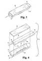
- FIG. 1is a first cross sectional view of a body fluid testing device according to one embodiment in a retracted position.
- FIG. 2is a second cross sectional view of the FIG. 1 body fluid testing device in an extended position.
- FIG. 3is a perspective view of the FIG. 1 device.
- FIG. 4is an exploded view of the FIG. 1 device.
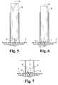
- FIG. 5is a rotated view of the FIG. 1 device before the incision is formed in the skin.
- FIG. 6is a rotated view of the FIG. 1 device forming an incision in the skin.
- FIG. 7is a rotated view of the FIG. 1 device during expression of fluid from the skin.
- FIG. 8is a perspective view of a body fluid testing device according to a second embodiment.
- FIG. 9is an exploded view of the FIG. 8 device.
- FIG. 10is an exploded view of a body fluid testing device according to a third embodiment.
- FIG. 11is a perspective view of the FIG. 10 device in a retracted position.
- FIG. 12is a perspective view of a body fluid testing device according to a fourth embodiment.
- FIG. 13is an exploded view of the FIG. 12 device.
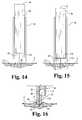
- FIG. 14is a rotated view of the FIG. 12 device before the incision is formed in the skin.
- FIG. 15is a rotated view of the FIG. 12 device forming an incision in the skin.
- FIG. 16is a rotated view of the FIG. 12 device during expression of fluid from the skin.
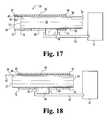
- FIG. 17is a third cross sectional view of the FIG. 1 body fluid testing device in a retracted position with a retraction mechanism.
- FIG. 18is a fourth cross sectional view of the FIG. 1 body fluid testing device in an extended position with an actuation mechanism.
- FIG. 19is a fifth cross sectional view of the body fluid testing device according to a fifth embodiment in a retracted position.
- FIG. 20is a fifth cross sectional view of the FIG. 19 body fluid testing device in an extended position.
- FIG. 21is a perspective view of the FIG. 19 device in an extended position.
- FIG. 22is an exploded view of the FIG. 19 device.
- FIG. 23is a rotated view of the FIG. 19 device before the incision is formed in the skin.
- FIG. 24is a rotated view of the FIG. 19 device forming an incision in the skin.
- One embodiment of the present inventiongenerally concerns a disposable body fluid testing device that reduces the number of steps involved in forming, collecting, and testing a bodily fluid sample from an incision.
- the body fluid testing device or cartridgeincludes an incision forming member, a housing, and a test strip that has an expression surface.
- the test stripattaches to the housing to form a cavity in which the incision forming member is slidably received.
- the cavityis sized to draw fluid via capillary action.
- the test stripis configured to draw fluid via capillary action.
- the body fluid testing deviceis operable by slidably moving the incision forming member to form an incision in the skin of a person.
- the body fluid testing deviceis operable to lance the skin with the incision forming member and express body fluid from the incision with the expression surface.
- the expression surfaceforces fluid from the incision.
- body fluidis expressed from the incision by pressing the test strip and the housing against the skin surrounding the incision.
- body fluidis collected via capillary action by the cavity and the body fluid is tested with the test strip.
- the test stripis configured to collect and test the body fluid from the incision.
- the body fluid testing deviceis disposable after testing the body fluid sample. Another body fluid testing device must be used for the next testing of a sample of body fluid. For example, after one use of the body fluid testing device the user disposes of the device and uses another body fluid testing device when the user needs to test body fluid at a later time.
- the body fluid testing device 30includes a test strip 40 for analyzing a bodily fluid.
- the test strip 40includes a skin contacting portion 42 and a distal portion 44 .
- the skin contacting portion 42includes an expression surface 46 capable of expressing fluid from the incision.
- the expression surface 46urges fluid from an incision site, such as by applying pressure to the area near the incision to milk or pump the fluid from the incision.
- the test strip 40can analyze fluid through such means as optical (e.g., reflectance, absorption, fluorescence, RAMAN, etc.), electrochemical (e.g. amperometric, potentiometric, or coulombmetric), and/or magnetic analysis.
- the test strip 40analyzes fluid optically through a chemical reagent.
- test strip 40analyzes fluid electrochemically through soluble chemical reagents and/or reagents fixed to an electrode.
- the test strip 40may have another shape.
- the test strip 40may include a rectangular, cylindrical, or an elliptical shape to form a test strip 40 , to name a few. Test strips are available commercially, for example under the trade name ACCU-CHEK GO® from Roche Diagnostics or ACCU-CHEK COMPACT® from Roche Diagnostics.
- the body fluid testing device 30includes an incision forming member 50 for forming an incision in the skin of a person.
- the incision forming member 50includes a sampling portion 52 and an opposite end portion 54 .
- the incision forming member 50also includes a test strip facing surface 56 and a housing facing surface 58 .
- the test strip facing surface 56is coated or made with a hydrophilic material to enhance capillary action or affinity.
- the housing facing surface 58is coated or made with a hydrophobic material to repel the bodily fluid towards the test strip facing surface 56 .
- the incision forming member 50is coated or made with a combination hydrophobic and hydrophilic material to direct fluid towards the test strip 40 . By directing fluid to the test strip 40 , the amount of fluid needed for testing can be reduced.
- the incision forming member 50is configured to form an incision in the skin.
- the incision forming member 50includes a needle 60 for forming the incision.
- An incisionmay include any opening in the skin that permits access to the bodily fluid.
- the needle 60forms an incision, but it should be appreciated that in other embodiments, the incision forming member 50 can include other devices to form an incision or rupture the skin.
- the incision forming member 50may include a lancet, a laser, a blade, and/or a high speed fluid stream to form an incision, to name a few.
- the needle 60includes a needle tip 62 for contacting the skin and a needle end 64 .
- the incision forming member 50is configured to slidably engage within a cavity 66 .
- the cavity 66encases the incision forming member 50 .
- the cavity 66is sized to draw fluid via capillary action.
- the cavity 66is sized such that expression surface 46 draws fluid.
- Different materialsmay have different affinities for a fluid, such that forming the expression surface 46 and the sampling portion 52 from different materials will provide a change in the capillary affinity between those portions.
- Capillary affinityis also changed by treating or coating the expression surface 46 , for example, to provide a resulting surface that is more or less hydrophilic.
- the capillary affinityis also changed by treating or coating the sampling portion 52 and/or the test strip facing surface 56 to provide a resulting surface that is more or less hydrophilic.
- the present inventionis operable in respect to any way in which the capillary affinity is varied.
- the incision forming member 50has a tab 68 .
- the tab 68actuates the incision forming member 50 when the tab 68 is engaged by an actuation mechanism of the type as generally known by those skilled in the art.
- the tab 68has a generally rectangular shape, but it should be appreciated that in other embodiments, the tab 68 may be shaped differently. For instance, the tab 68 may be circular or elliptical in shape.
- the body fluid testing device 30includes a housing 70 attached to the test strip 40 that forms the cavity 66 .
- the housing 70includes a first portion 72 and an opposite second portion 74 .
- the housing 70also includes an interior surface 76 and an exterior surface 78 .
- the housing 70includes an opening 80 that is configured to receive the tab 68 of the incision forming member 50 .
- the opening 80has a generally rectangular shape, but it should be appreciated that in other embodiments, the opening 80 may be shaped differently.
- the opening 80may be a slot, a slit, or a rectangle with rounded ends in shape, or any other shape that mates with tab 68 .
- the tab 68glides in the opening 80 .
- the length of the opening 80in the illustrated embodiment is beneficial as that length determines the limits of movement of the tab 68 and the penetration depth into the skin of the person by the incision forming member 50 .
- an actuation mechanismmay be coupled to the tab 68 to further limit the movement of the tab 68 in the opening 80 .
- the depth of penetration of the incisiongenerally controls the fluid produced, particularly in combination with the characteristics of the incision site.
- the present inventionis useful with various bodily fluids, including blood or interstitial fluid.
- the body fluid testing devicemay be configured for production of either blood or interstitial fluid, for example, by controlling the distance which the incision forming device extends into the skin of the user. For example, a depth of 0.25 mm to 4 mm will typically produce blood from the dermis, while a depth of 0.05 mm to 0.5 mm will produce interstitial fluid from the epidermis.
- the test strip 40is attached to the housing 70 such that the cavity 66 is formed in which the incision forming member 50 is slidably received. It should be appreciated, however, that the test strip 40 can be attached to the housing 70 in other manners. By way of nonlimiting examples, the test strip 40 can be attached to the housing 70 through an adhesive, a clamp mechanism, welded, and/or by a snap mechanism, to name a few. Still further, the test strip 40 and the housing 70 could be molded as one body instead of two separate attachable elements. In the illustrated embodiment, the housing 70 has a half-pipe shape and the incision forming member 50 has a half-cylindrical shape.
- the half-pipe shape of the housing 70is beneficial as that shape is easy to manufacture and grasp by the user. It should be appreciated that the housing 70 and incision forming member 50 may be shaped differently in other embodiments. For instance, the housing 70 may be a rectangle receptacle and the incision forming member 50 may be rectangular in shape. In the illustrated embodiment, the cavity 66 has a half-cylindrical shape but it should be appreciated that the cavity 66 may be shaped differently in other embodiments.
- the test strip 40attaches to the housing 70 to align skin contacting portion 42 with first portion 72 .
- the skin contacting portion 42 and the first portion 72express fluid from an incision, such as by applying pressure to the area surrounding the incision to milk or pump the fluid from the incision.
- the skin contacting portion 42 and the first portion 72express fluid through such means as applying pressure to the skin surrounding the incision, and/or squeezing or constricting the skin surrounding the incision.
- FIGS. 1 and 5illustrate the relative position of the incision forming member 50 such that the needle tip 62 is retracted beyond the skin contacting portion 42 towards the distal portion 44 of the test strip 40 before the body fluid testing device 30 is placed on the user's skin S.
- the incision forming member 50is retracted by retraction mechanisms as shown in FIG. 17 .
- the retraction mechanism 51has an arm 53 that is coupled to the tab 68 to retract the incision forming member 50 .
- the arm 53 of the retraction mechanism 51is coupled to the end portion 54 to retract the incision forming member 50 .
- FIGS. 2 and 6illustrate the relative position of incision forming member 50 after the end portion 54 is driven toward the sampling portion 52 thereby lancing the user's skin S with the needle tip 62 to form incision I.
- the incision forming member 50can be actuated or driven towards the skin S using actuation mechanisms of a lancing device as shown in FIG. 18 .
- the actuation mechanism 61has an arm 63 that is coupled to the tab 68 to drive the incision forming member 50 towards the skin S.
- the arm 63 of the actuation mechanism 61is coupled to the end portion 54 to drive the incision forming member 50 towards the skin S. After an incision I in the skin S is formed, the needle tip 62 is withdrawn from the user's skin S.
- FIGS. 1 and 5also illustrate the relative position of the incision forming member 50 after the sampling portion 52 is retracted towards the end portion 54 thereby removing the needle tip 62 from the user's skin S.
- the incision forming member 50can be retracted by a retraction mechanism as shown in FIG. 17 .
- the arm 53 of the retraction mechanism 51is attached to the tab 68 to move the tab 68 within the opening 80 thereby retracting the incision forming member 50 .
- the arm 53 of the retraction mechanism 51is attached to the end portion 54 to retract the incision forming member 50 .
- FIG. 7illustrates expressing bodily fluid from incision I according to one embodiment where the skin contacting portion 42 remains in contact with the skin S.
- the body fluid Bis expressed from the incision I.
- the expression surface 46is pressed against the skin S to urge fluid B from the incision I.
- the skin contacting portion 42 of the test strip 40 and the first portion 72 of the housing 70are pressed against the skin S to urge fluid B from the incision I.
- the skin contacting portion 42 and the first portion 72express fluid B from the incision I, such as by applying pressure to the skin S surrounding the incision I to milk or pump the fluid B from the incision I.
- the cavity 66collects fluid B from the incision I via capillary action.
- the body fluid Bis also drawn onto the test strip 40 for testing via the capillary action of the cavity 66 .
- the expression surface 46 of test strip 40is configured to collect the body fluid B. Further, the expression surface 46 is coated with a hydrophilic material to collect body fluid B via capillary action.
- the body fluid testing device 30 illustrated in FIGS. 1 , 2 , 5 , 6 and 7improves the speed and ease of use for a device that simultaneously expresses and collects bodily fluid for testing. With the expression surface 46 and the cavity 66 combined into one device, the user will quickly be able to express and collect bodily fluid. It should be appreciated that the body fluid testing device 30 is useful for alternate site testing where enough fluid must be expressed and collected from the incision to test the fluid. In one embodiment, the body fluid testing device 30 is disposable thus leaving the retraction mechanism and/or the actuation mechanism for a later use with another body fluid testing device 30 . In the illustrated embodiment, the body fluid testing device 30 is disposed as a single unit thereby reducing the hazardous waste.
- the body fluid testing device 30includes an end cap 90 to detachably cover a front portion 92 of the testing device 30 .
- the end cap 90includes a forward end wall 94 opposite a rear end 96 configured to store the front portion 92 .
- the end cap 90is a half-cylindrical shape. In other forms, the end cap 90 may be rectangular, oval, ellipitical, or any other shape that matches the front portion 92 .
- the rear end 96includes an opening 98 for storing the needle tip 62 and the needle 60 .
- Various configurationscan be used to attach end cap 90 to front portion 92 . For example, end cap 90 may be pushed onto front portion 92 .
- the end cap 90is removed from the front portion 92 .
- the end cap 90may be detached from the front portion 92 by turning, rotating, or pulling the end cap 90 relative to the front portion 92 .
- other forms of attaching and/or detaching end cap 90 from front portion 92may be used.
- the placement of the end cap 90 onto the front portion 92protects the sterility of the needle tip 62 and the needle 60 . Further, the end cap 90 is detached from the front portion 92 to expose needle tip 62 for use. After use of the body fluid testing device 30 , the end cap 90 is placed onto the front portion 92 . As should be appreciated, the placement of the end cap 90 onto the front portion 92 after use of the body fluid testing device 30 ensures a safe and hygienic disposal of the testing device 30 by enclosing the front portion 92 that may be contaminated with body fluid.
- FIGS. 10 and 11illustrate the body fluid testing device 30 according to an alternate embodiment of the present invention.
- the incision forming member 50 and the housing 70are detachably molded to form one body.
- the incision forming member 50is attached to the housing 70 via a pair of connectors 100 .
- the pair of connectors 100are made of any material that allows the incision forming member 50 to detach or separate from the housing 70 .
- the connectors 100may be made of a flexible plastic material or rubber, to name a few.
- the housing 70will be rotated such that the opening 80 aligns over the tab 68 of the incision forming member 50 .
- the userin operation of the body fluid testing device 30 the user will rotate the housing 70 such that the opening 80 aligns over the tab 68 of the incision forming member 50 .
- the opening 80receives the tab 68 .
- the test strip 40attaches to the housing 70 .
- the needle tip 62is retracted beyond the skin contacting portion 42 towards the distal portion 44 of the test strip 40 .
- the pair of connectors 100are removed from the incision forming member 50 and the housing 70 to detach the end portion 54 of the incision forming member 50 from the second portion 74 of the housing 70 .
- the pair of connectors 100are severed to detach the end portion 54 of the incision forming member 50 from the second portion 74 of the housing 70 .
- the removal and/or severance of the pair of connectors 100frees the movement of the incision forming member 50 with respect to the housing 70 .
- the pair of connectors 100are configured to allow unlimited movement of the incision forming member 50 with respect to the housing 70 .
- the body fluid testing device 30includes an extension 110 .
- Extension 110has a skin contacting portion 112 for contacting skin and a distal portion 114 for contacting first portion 72 .
- Extension 110extends from first portion 72 to align with skin contacting portion 42 of test strip 40 .
- extension 110 and test strip 40are aligned in a parallel relationship.
- the incision forming member 50is configured to slidably engage within cavity 66 however the sampling portion 52 can not extend beyond the distal portion 114 .
- the alignment of extension 110 and test strip 40forms a passageway 120 .
- the passageway 120is sized to draw fluid via capillary action or affinity.
- the passageway 120is sized such that test strip surface 46 draws fluid.
- Different materialsmay have different affinities for a fluid, such that forming the expression surface 46 and the extension 110 from different materials will provide a change in the capillary affinity between those portions. Treating or coating the expression surface 46 to provide a resulting surface that is more or less hydrophilic changes the capillary affinity.
- the capillary affinitycould also be changed by treating or coating the extension 110 to provide a resulting surface that is more or less hydrophilic.
- the present inventionis operable in respect to any way in which the capillary affinity is varied.
- FIGS. 12 and 14illustrate the relative position of the incision forming member 50 such that the needle tip 62 is retracted beyond the skin contacting portion 112 towards distal portion 114 before the body fluid testing device 30 is placed on the user's skin S.
- the incision forming member 50is retracted by retraction mechanisms wherein the retraction mechanism is coupled to the tab 68 to retract the incision forming member 50 .
- the retraction mechanismis coupled to the end portion 54 to retract the incision forming member 50 .
- FIG. 15illustrates the relative position of incision forming member 50 after the end portion 54 is driven toward the sampling portion 52 thereby driving the needle tip 62 through the passageway 120 and into the user's skin S with the needle tip 62 to form an incision I.
- the needle tip 62 or another device to form an incision in skinextends through passageway 120 beyond extension 110 to form an incision in skin.
- the incision forming member 50can be actuated or driven toward the skin S using actuation mechanisms of a lancing device.
- the actuation mechanismcan be coupled to the tab 68 or the end portion 54 to drive the incision forming member 50 towards the skin S. Also illustrated in FIG. 14 , is the needle tip 62 withdrawn from the skin S and the sampling portion 52 is retracted towards the end portion 54 .
- FIG. 16illustrates expressing bodily fluid from incision I according to one embodiment where the skin contacting portion 42 and the skin contacting portion 112 remain in contact with the skin S.
- the body fluid Bis expressed from the incision I.
- the skin contacting portion 42 and the skin contacting portion 112express body fluid B from the incision I, such as by applying pressure to the skin S surrounding the incision I to milk or pump the fluid B from the incision I.
- the body fluid Bis drawn onto the test strip 40 for testing via the capillary action of the passageway 120 . After the body fluid B is expressed, the expression surface 46 of the test strip 40 collects the body fluid B.
- the body fluid testing device 30includes a cover 130 to attach the test strip 40 to the housing 70 .
- Cover 130extends from the second portion 74 towards the first portion 72 of the housing 70 .
- the cover 130is adhesively attached to the housing 70 .
- cover 130can be attached to the housing 70 by a clamp mechanism, welding, and/or by a snap mechanism, to name a few.
- the incision forming member 50is configured to slidably engage within passageway 140 .
- the alignment of test strip 40 and housing 70forms a passageway 140 .
- the passageway 140is sized to draw fluid via capillary action or affinity.
- the passageway 140is sized such that test strip surface 46 draws fluid.
- Different materialsmay have different affinities for a fluid, such that forming the expression surface 46 and the sampling portion 52 from different materials will provide a change in the capillary affinity between those portions.
- Treating or coating the expression surface 46 to provide a resulting surface that is more or less hydrophilicchanges the capillary affinity.
- the capillary affinitycould also be changed by treating or coating the expression surface 46 to provide a resulting surface that is more or less hydrophilic.
- the present inventionis operable in respect to any way in which the capillary affinity is varied.
- the incision forming member 50includes a tab 68 .
- a retraction mechanism or an actuation mechanismis coupled to the tab 68 to limit the motion or movement of the incision forming member 50 in the passageway 140 .
- a retraction mechanism 51has an arm 53 that is coupled to the tab 68 to retract the incision forming member 50 .
- the test strip 40 in FIGS. 23 and 24is removed for clarity. In operation, the arm 53 of the retraction mechanism 51 retracts the needle tip 62 beyond the skin contacting portion 42 towards the distal portion 44 of the test strip 40 . As shown in FIG.
- an actuation mechanism 61has an arm 63 that is coupled to the tab 68 to actuate the incision forming member 50 .
- the arm 63 of the actuation mechanism 61is coupled to the tab 68 to drive the incision forming member 50 towards the skin S to form an incision I in the user's skin with the needle tip 62 .
- the needle tip 62is withdrawn from the user's skin S by retracting the incision forming member 50 .
- the incision forming member 50is retracted by the arm 53 of the retraction mechanism 51 as shown in FIG. 23 .
- the arm 53 of the retraction mechanism 51is attached to the tab 68 to move the tab 68 thereby removing the needle tip 62 from the user's skin S and retracting the incision forming member 50 .
Landscapes
- Health & Medical Sciences (AREA)
- Life Sciences & Earth Sciences (AREA)
- Engineering & Computer Science (AREA)
- Medical Informatics (AREA)
- Surgery (AREA)
- Biophysics (AREA)
- Pathology (AREA)
- Hematology (AREA)
- Biomedical Technology (AREA)
- Heart & Thoracic Surgery (AREA)
- Veterinary Medicine (AREA)
- Molecular Biology (AREA)
- Physics & Mathematics (AREA)
- Animal Behavior & Ethology (AREA)
- General Health & Medical Sciences (AREA)
- Public Health (AREA)
- Dermatology (AREA)
- Manufacturing & Machinery (AREA)
- Pain & Pain Management (AREA)
- Measurement Of The Respiration, Hearing Ability, Form, And Blood Characteristics Of Living Organisms (AREA)
Abstract
Description
Claims (17)
Priority Applications (6)
| Application Number | Priority Date | Filing Date | Title |
|---|---|---|---|
| US10/872,945US7766845B2 (en) | 2004-06-21 | 2004-06-21 | Disposable lancet and lancing cap combination for increased hygiene |
| PCT/EP2005/006668WO2005122897A1 (en) | 2004-06-21 | 2005-06-21 | Disposable lancet and lancing cap combination for increased hygiene |
| JP2007517178AJP2008503289A (en) | 2004-06-21 | 2005-06-21 | Disposable lancet and lancet incision cap combination for improved hygiene |
| EP05762912AEP1763318A1 (en) | 2004-06-21 | 2005-06-21 | Disposable lancet and lancing cap combination for increased hygiene |
| CN2005800204224ACN101102719B (en) | 2004-06-21 | 2005-06-21 | Disposable Lancet and Lancet Cap Combination for Improved Hygiene |
| CA002570204ACA2570204A1 (en) | 2004-06-21 | 2005-06-21 | Disposable lancet and lancing cap combination for increased hygiene |
Applications Claiming Priority (1)
| Application Number | Priority Date | Filing Date | Title |
|---|---|---|---|
| US10/872,945US7766845B2 (en) | 2004-06-21 | 2004-06-21 | Disposable lancet and lancing cap combination for increased hygiene |
Publications (2)
| Publication Number | Publication Date |
|---|---|
| US20050283094A1 US20050283094A1 (en) | 2005-12-22 |
| US7766845B2true US7766845B2 (en) | 2010-08-03 |
Family
ID=34981515
Family Applications (1)
| Application Number | Title | Priority Date | Filing Date |
|---|---|---|---|
| US10/872,945Expired - Fee RelatedUS7766845B2 (en) | 2004-06-21 | 2004-06-21 | Disposable lancet and lancing cap combination for increased hygiene |
Country Status (6)
| Country | Link |
|---|---|
| US (1) | US7766845B2 (en) |
| EP (1) | EP1763318A1 (en) |
| JP (1) | JP2008503289A (en) |
| CN (1) | CN101102719B (en) |
| CA (1) | CA2570204A1 (en) |
| WO (1) | WO2005122897A1 (en) |
Cited By (1)
| Publication number | Priority date | Publication date | Assignee | Title |
|---|---|---|---|---|
| US20090216155A1 (en)* | 2005-11-21 | 2009-08-27 | Nicholas Long | Test Device |
Families Citing this family (87)
| Publication number | Priority date | Publication date | Assignee | Title |
|---|---|---|---|---|
| US6036924A (en) | 1997-12-04 | 2000-03-14 | Hewlett-Packard Company | Cassette of lancet cartridges for sampling blood |
| US6391005B1 (en) | 1998-03-30 | 2002-05-21 | Agilent Technologies, Inc. | Apparatus and method for penetration with shaft having a sensor for sensing penetration depth |
| US8641644B2 (en) | 2000-11-21 | 2014-02-04 | Sanofi-Aventis Deutschland Gmbh | Blood testing apparatus having a rotatable cartridge with multiple lancing elements and testing means |
| DE10057832C1 (en) | 2000-11-21 | 2002-02-21 | Hartmann Paul Ag | Blood analysis device has syringe mounted in casing, annular mounting carrying needles mounted behind test strip and being swiveled so that needle can be pushed through strip and aperture in casing to take blood sample |
| EP1395185B1 (en) | 2001-06-12 | 2010-10-27 | Pelikan Technologies Inc. | Electric lancet actuator |
| JP4209767B2 (en) | 2001-06-12 | 2009-01-14 | ペリカン テクノロジーズ インコーポレイテッド | Self-optimized cutting instrument with adaptive means for temporary changes in skin properties |
| US9795747B2 (en) | 2010-06-02 | 2017-10-24 | Sanofi-Aventis Deutschland Gmbh | Methods and apparatus for lancet actuation |
| US7041068B2 (en) | 2001-06-12 | 2006-05-09 | Pelikan Technologies, Inc. | Sampling module device and method |
| US9427532B2 (en) | 2001-06-12 | 2016-08-30 | Sanofi-Aventis Deutschland Gmbh | Tissue penetration device |
| US7344507B2 (en) | 2002-04-19 | 2008-03-18 | Pelikan Technologies, Inc. | Method and apparatus for lancet actuation |
| JP4272051B2 (en) | 2001-06-12 | 2009-06-03 | ペリカン テクノロジーズ インコーポレイテッド | Blood sampling apparatus and method |
| US9226699B2 (en) | 2002-04-19 | 2016-01-05 | Sanofi-Aventis Deutschland Gmbh | Body fluid sampling module with a continuous compression tissue interface surface |
| WO2002101359A2 (en) | 2001-06-12 | 2002-12-19 | Pelikan Technologies, Inc. | Integrated blood sampling analysis system with multi-use sampling module |
| US7981056B2 (en) | 2002-04-19 | 2011-07-19 | Pelikan Technologies, Inc. | Methods and apparatus for lancet actuation |
| US8337419B2 (en) | 2002-04-19 | 2012-12-25 | Sanofi-Aventis Deutschland Gmbh | Tissue penetration device |
| AU2002344825A1 (en) | 2001-06-12 | 2002-12-23 | Pelikan Technologies, Inc. | Method and apparatus for improving success rate of blood yield from a fingerstick |
| US7749174B2 (en) | 2001-06-12 | 2010-07-06 | Pelikan Technologies, Inc. | Method and apparatus for lancet launching device intergrated onto a blood-sampling cartridge |
| US7344894B2 (en) | 2001-10-16 | 2008-03-18 | Agilent Technologies, Inc. | Thermal regulation of fluidic samples within a diagnostic cartridge |
| US7563232B2 (en) | 2002-04-19 | 2009-07-21 | Pelikan Technologies, Inc. | Method and apparatus for penetrating tissue |
| US7708701B2 (en) | 2002-04-19 | 2010-05-04 | Pelikan Technologies, Inc. | Method and apparatus for a multi-use body fluid sampling device |
| US7141058B2 (en) | 2002-04-19 | 2006-11-28 | Pelikan Technologies, Inc. | Method and apparatus for a body fluid sampling device using illumination |
| US8267870B2 (en) | 2002-04-19 | 2012-09-18 | Sanofi-Aventis Deutschland Gmbh | Method and apparatus for body fluid sampling with hybrid actuation |
| US7582099B2 (en) | 2002-04-19 | 2009-09-01 | Pelikan Technologies, Inc | Method and apparatus for penetrating tissue |
| US7491178B2 (en) | 2002-04-19 | 2009-02-17 | Pelikan Technologies, Inc. | Method and apparatus for penetrating tissue |
| US9314194B2 (en) | 2002-04-19 | 2016-04-19 | Sanofi-Aventis Deutschland Gmbh | Tissue penetration device |
| US7524293B2 (en) | 2002-04-19 | 2009-04-28 | Pelikan Technologies, Inc. | Method and apparatus for penetrating tissue |
| US8579831B2 (en) | 2002-04-19 | 2013-11-12 | Sanofi-Aventis Deutschland Gmbh | Method and apparatus for penetrating tissue |
| US7547287B2 (en) | 2002-04-19 | 2009-06-16 | Pelikan Technologies, Inc. | Method and apparatus for penetrating tissue |
| US8784335B2 (en) | 2002-04-19 | 2014-07-22 | Sanofi-Aventis Deutschland Gmbh | Body fluid sampling device with a capacitive sensor |
| US7648468B2 (en) | 2002-04-19 | 2010-01-19 | Pelikon Technologies, Inc. | Method and apparatus for penetrating tissue |
| US9248267B2 (en) | 2002-04-19 | 2016-02-02 | Sanofi-Aventis Deustchland Gmbh | Tissue penetration device |
| US7892183B2 (en) | 2002-04-19 | 2011-02-22 | Pelikan Technologies, Inc. | Method and apparatus for body fluid sampling and analyte sensing |
| US7674232B2 (en) | 2002-04-19 | 2010-03-09 | Pelikan Technologies, Inc. | Method and apparatus for penetrating tissue |
| US7331931B2 (en) | 2002-04-19 | 2008-02-19 | Pelikan Technologies, Inc. | Method and apparatus for penetrating tissue |
| US7297122B2 (en) | 2002-04-19 | 2007-11-20 | Pelikan Technologies, Inc. | Method and apparatus for penetrating tissue |
| US7717863B2 (en) | 2002-04-19 | 2010-05-18 | Pelikan Technologies, Inc. | Method and apparatus for penetrating tissue |
| US7410468B2 (en) | 2002-04-19 | 2008-08-12 | Pelikan Technologies, Inc. | Method and apparatus for penetrating tissue |
| US8221334B2 (en) | 2002-04-19 | 2012-07-17 | Sanofi-Aventis Deutschland Gmbh | Method and apparatus for penetrating tissue |
| US7229458B2 (en) | 2002-04-19 | 2007-06-12 | Pelikan Technologies, Inc. | Method and apparatus for penetrating tissue |
| US7481776B2 (en) | 2002-04-19 | 2009-01-27 | Pelikan Technologies, Inc. | Method and apparatus for penetrating tissue |
| US7909778B2 (en) | 2002-04-19 | 2011-03-22 | Pelikan Technologies, Inc. | Method and apparatus for penetrating tissue |
| US8702624B2 (en) | 2006-09-29 | 2014-04-22 | Sanofi-Aventis Deutschland Gmbh | Analyte measurement device with a single shot actuator |
| US7291117B2 (en) | 2002-04-19 | 2007-11-06 | Pelikan Technologies, Inc. | Method and apparatus for penetrating tissue |
| US7976476B2 (en) | 2002-04-19 | 2011-07-12 | Pelikan Technologies, Inc. | Device and method for variable speed lancet |
| US7374544B2 (en) | 2002-04-19 | 2008-05-20 | Pelikan Technologies, Inc. | Method and apparatus for penetrating tissue |
| US7371247B2 (en) | 2002-04-19 | 2008-05-13 | Pelikan Technologies, Inc | Method and apparatus for penetrating tissue |
| US9795334B2 (en) | 2002-04-19 | 2017-10-24 | Sanofi-Aventis Deutschland Gmbh | Method and apparatus for penetrating tissue |
| US7232451B2 (en) | 2002-04-19 | 2007-06-19 | Pelikan Technologies, Inc. | Method and apparatus for penetrating tissue |
| US7901362B2 (en) | 2002-04-19 | 2011-03-08 | Pelikan Technologies, Inc. | Method and apparatus for penetrating tissue |
| US7815579B2 (en) | 2005-03-02 | 2010-10-19 | Roche Diagnostics Operations, Inc. | Dynamic integrated lancing test strip with sterility cover |
| US8052926B2 (en)* | 2002-12-27 | 2011-11-08 | Roche Diagnostics Operations, Inc. | Method for manufacturing a sterilized lancet integrated biosensor |
| US7214200B2 (en)* | 2002-12-30 | 2007-05-08 | Roche Diagnostics Operations, Inc. | Integrated analytical test element |
| US7211052B2 (en)* | 2002-12-30 | 2007-05-01 | Roche Diagnostics Operations, Inc. | Flexible test strip lancet device |
| DE60332043D1 (en)* | 2002-12-30 | 2010-05-20 | Roche Diagnostics Gmbh | CAPILLARY TUBE TOP DESIGN TO SUPPORT BLOOD FLOW |
| US8574895B2 (en) | 2002-12-30 | 2013-11-05 | Sanofi-Aventis Deutschland Gmbh | Method and apparatus using optical techniques to measure analyte levels |
| US7850621B2 (en) | 2003-06-06 | 2010-12-14 | Pelikan Technologies, Inc. | Method and apparatus for body fluid sampling and analyte sensing |
| WO2006001797A1 (en) | 2004-06-14 | 2006-01-05 | Pelikan Technologies, Inc. | Low pain penetrating |
| EP1635700B1 (en) | 2003-06-13 | 2016-03-09 | Sanofi-Aventis Deutschland GmbH | Apparatus for a point of care device |
| US8282576B2 (en) | 2003-09-29 | 2012-10-09 | Sanofi-Aventis Deutschland Gmbh | Method and apparatus for an improved sample capture device |
| EP1680014A4 (en) | 2003-10-14 | 2009-01-21 | Pelikan Technologies Inc | METHOD AND DEVICE FOR A VARIABLE USER INTERFACE |
| US8668656B2 (en) | 2003-12-31 | 2014-03-11 | Sanofi-Aventis Deutschland Gmbh | Method and apparatus for improving fluidic flow and sample capture |
| US7822454B1 (en) | 2005-01-03 | 2010-10-26 | Pelikan Technologies, Inc. | Fluid sampling device with improved analyte detecting member configuration |
| WO2006011062A2 (en) | 2004-05-20 | 2006-02-02 | Albatros Technologies Gmbh & Co. Kg | Printable hydrogel for biosensors |
| WO2005120365A1 (en) | 2004-06-03 | 2005-12-22 | Pelikan Technologies, Inc. | Method and apparatus for a fluid sampling device |
| US7645241B2 (en)* | 2004-09-09 | 2010-01-12 | Roche Diagnostics Operations, Inc. | Device for sampling bodily fluids |
| US7604604B2 (en)* | 2004-09-09 | 2009-10-20 | Roche Diagnostics Operations, Inc. | Device for sampling bodily fluids |
| US7488298B2 (en)* | 2004-10-08 | 2009-02-10 | Roche Diagnostics Operations, Inc. | Integrated lancing test strip with capillary transfer sheet |
| US8652831B2 (en) | 2004-12-30 | 2014-02-18 | Sanofi-Aventis Deutschland Gmbh | Method and apparatus for analyte measurement test time |
| US7935063B2 (en) | 2005-03-02 | 2011-05-03 | Roche Diagnostics Operations, Inc. | System and method for breaking a sterility seal to engage a lancet |
| EP1868491B1 (en)* | 2005-03-24 | 2011-05-18 | Roche Diagnostics GmbH | Analyzing means with lancet and test element |
| EP1714613A1 (en)* | 2005-04-22 | 2006-10-25 | F. Hoffmann-La Roche Ag | Analyzing means |
| EP1785090A1 (en)* | 2005-11-10 | 2007-05-16 | F.Hoffmann-La Roche Ag | Lancet device and system for skin detection |
| GB2434540A (en) | 2006-01-27 | 2007-08-01 | Owen Mumford Ltd | Lancet |
| DE502007006032D1 (en)* | 2007-07-17 | 2011-02-03 | Roche Diagnostics Gmbh | Device for obtaining body fluid |
| EP2265324B1 (en) | 2008-04-11 | 2015-01-28 | Sanofi-Aventis Deutschland GmbH | Integrated analyte measurement system |
| US9375169B2 (en) | 2009-01-30 | 2016-06-28 | Sanofi-Aventis Deutschland Gmbh | Cam drive for managing disposable penetrating member actions with a single motor and motor and control system |
| US8758267B2 (en)* | 2009-03-17 | 2014-06-24 | Nova Biomedical Corporation | Modified lancet carrier for single-use lancet sensor assembly |
| US8061004B2 (en) | 2009-08-20 | 2011-11-22 | Roche Diagnostics Operations, Inc. | Method of manufacturing a test strip |
| CA2793554C (en) | 2010-03-19 | 2018-04-03 | Atomo Diagnostics Pty Limited | Bodily fluid diagnostic system |
| US8965476B2 (en) | 2010-04-16 | 2015-02-24 | Sanofi-Aventis Deutschland Gmbh | Tissue penetration device |
| HUE028577T2 (en) | 2010-10-15 | 2016-12-28 | Atomo Diagnostics Pty Ltd | Sampling assembly |
| US9752990B2 (en) | 2013-09-30 | 2017-09-05 | Honeywell International Inc. | Low-powered system for driving a fuel control mechanism |
| JP6018172B2 (en)* | 2011-04-12 | 2016-11-02 | エフ ホフマン−ラ ロッシュ アクチェン ゲゼルシャフト | Analytical aids |
| US9999369B2 (en)* | 2012-03-13 | 2018-06-19 | Purdue Research Foundation | Laser-scribed ferrogel sensor with magnetic particles |
| CN102626313B (en)* | 2012-04-13 | 2015-04-22 | 江苏健裕健康医疗器械有限公司 | Split welding fixed disposable blood taking needle |
| AU345335S (en) | 2012-10-03 | 2012-11-02 | Atomo Diagnostics Pty Ltd | Device for collecting and testing a fluid sample |
| US10595763B2 (en) | 2013-11-21 | 2020-03-24 | Atomo Diagnostics Pty Limited | Integrated testing devices with control vessel for fluid control |
Citations (61)
| Publication number | Priority date | Publication date | Assignee | Title |
|---|---|---|---|---|
| US4360016A (en) | 1980-07-01 | 1982-11-23 | Transidyne General Corp. | Blood collecting device |
| US4416279A (en)* | 1981-06-19 | 1983-11-22 | Lindner James A | Capillary blood sampling device |
| EP0199484A2 (en) | 1985-04-08 | 1986-10-29 | Audio Bionics Inc | Medical system |
| US4653513A (en) | 1985-08-09 | 1987-03-31 | Dombrowski Mitchell P | Blood sampler |
| US4677979A (en)* | 1984-09-20 | 1987-07-07 | Becton, Dickinson And Company | Lancet |
| US4850973A (en) | 1987-10-16 | 1989-07-25 | Pavel Jordon & Associates | Plastic device for injection and obtaining blood samples |
| US4869249A (en) | 1987-05-01 | 1989-09-26 | Owen Mumford Limited | Blood sampling devices |
| US4889117A (en) | 1989-02-17 | 1989-12-26 | Stevens Peter A | Disposable lancet |
| US4895147A (en)* | 1988-10-28 | 1990-01-23 | Sherwood Medical Company | Lancet injector |
| US4920977A (en) | 1988-10-25 | 1990-05-01 | Becton, Dickinson And Company | Blood collection assembly with lancet and microcollection tube |
| US4924879A (en) | 1988-10-07 | 1990-05-15 | Brien Walter J O | Blood lancet device |
| US5054499A (en) | 1989-03-27 | 1991-10-08 | Swierczek Remi D | Disposable skin perforator and blood testing device |
| US5217480A (en)* | 1992-06-09 | 1993-06-08 | Habley Medical Technology Corporation | Capillary blood drawing device |
| US5318584A (en) | 1992-04-13 | 1994-06-07 | Boehringer Mannheim Gmbh | Blood lancet device for withdrawing blood for diagnostic purposes |
| US5320607A (en) | 1992-02-13 | 1994-06-14 | Kabushiki Kaisya Advance | Simple blood sampling device |
| US5324303A (en) | 1992-09-25 | 1994-06-28 | Amg Medical, Inc. | Combined lancet and multi-function cap and lancet injector for use therewith |
| US5368047A (en) | 1993-04-28 | 1994-11-29 | Nissho Corporation | Suction-type blood sampler |
| US5402798A (en) | 1991-07-18 | 1995-04-04 | Swierczek; Remi | Disposable skin perforator and blood testing device |
| US5439473A (en)* | 1993-12-13 | 1995-08-08 | Modulohm A/S | Safety lancet |
| US5554166A (en) | 1993-06-21 | 1996-09-10 | Boehringer Mannheim Gmbh | Blood lancet device for withdrawing blood for diagnostic purposes |
| US5582184A (en) | 1993-10-13 | 1996-12-10 | Integ Incorporated | Interstitial fluid collection and constituent measurement |
| US5628764A (en) | 1995-03-21 | 1997-05-13 | Schraga; Steven | Collar lancet device |
| US5700695A (en)* | 1994-06-30 | 1997-12-23 | Zia Yassinzadeh | Sample collection and manipulation method |
| US5741288A (en)* | 1996-06-27 | 1998-04-21 | Chemtrak, Inc. | Re-armable single-user safety finger stick device having reset for multiple use by a single patient |
| US6149608A (en)* | 1997-06-21 | 2000-11-21 | Owen Mumford Limited | Skin prickers |
| US6228100B1 (en)* | 1999-10-25 | 2001-05-08 | Steven Schraga | Multi-use lancet device |
| US6299626B1 (en)* | 1997-06-02 | 2001-10-09 | Paul Viranyi | Skin pricker |
| US6315738B1 (en)* | 1999-01-04 | 2001-11-13 | Terumo Kabushiki Kaisha | Assembly having lancet and means for collecting and detecting body fluid |
| US20010041904A1 (en)* | 2000-04-05 | 2001-11-15 | Adam Heller | Reusable ceramic skin-piercing device |
| US6322574B1 (en) | 1999-10-29 | 2001-11-27 | Medical Plastic Devices M.P.D. Inc. | Disposable lancet |
| US6322575B1 (en) | 2000-01-05 | 2001-11-27 | Steven Schraga | Lancet depth adjustment assembly |
| US20020004196A1 (en) | 2000-07-10 | 2002-01-10 | Bayer Corporation | Thin lance and test sensor having same |
| US20020016606A1 (en) | 2000-06-09 | 2002-02-07 | Piet Moerman | Cap for a lancing device |
| US6358265B1 (en)* | 2000-07-18 | 2002-03-19 | Specialized Health Products, Inc. | Single-step disposable safety lancet apparatus and methods |
| US20020087180A1 (en) | 2000-12-29 | 2002-07-04 | Searle Stephen D. | Blood lancet |
| EP1035919B1 (en) | 1997-12-04 | 2002-07-24 | Roche Diagnostics GmbH | Device for the capillary transport of liquid |
| EP1035920B1 (en) | 1997-12-04 | 2002-07-24 | Roche Diagnostics GmbH | Capillary active test element having support and covering |
| WO2002056751A2 (en) | 2001-01-22 | 2002-07-25 | Roche Diagnostics Gmbh | Lancet device having capillary action |
| US20020120216A1 (en)* | 2000-09-26 | 2002-08-29 | Michael Fritz | Lancet system |
| US20020151920A1 (en) | 1999-12-08 | 2002-10-17 | Jeremy Marshall | Integration of a lancette with its capturing and removing cap |
| US20020168290A1 (en) | 2002-05-09 | 2002-11-14 | Yuzhakov Vadim V. | Physiological sample collection devices and methods of using the same |
| US6514270B1 (en) | 2000-11-10 | 2003-02-04 | Steven Schraga | Single use lancet device |
| EP1285629A1 (en) | 2001-01-19 | 2003-02-26 | Matsushita Electric Industrial Co., Ltd. | Lancet-integrated sensor, measurer for lancet-integrated sensor, and cartridge |
| US20030050573A1 (en) | 2001-08-29 | 2003-03-13 | Hans-Juergen Kuhr | Analytical device with lancet and test element |
| US6540762B1 (en) | 1998-07-09 | 2003-04-01 | November Aktiengesellschaft Gesellschaft Fur Molekulare Medizin | Device for perforating skin |
| US20030100913A1 (en) | 2001-10-09 | 2003-05-29 | Guoping Shi | Depth adjustable cap of lancing device |
| US6576101B1 (en)* | 1997-02-06 | 2003-06-10 | Therasense, Inc. | Small volume in vitro analyte sensor |
| US20030109895A1 (en)* | 2001-12-07 | 2003-06-12 | Taylor William C. | Keyed lancet with generic mounting compatibility |
| US20030109777A1 (en) | 2001-12-07 | 2003-06-12 | Kloepfer Hans G. | Consolidated body fluid testing device and method |
| US20030144609A1 (en)* | 2002-01-31 | 2003-07-31 | Kennedy Gwenn E. | Single use device for blood microsampling |
| EP1402812A1 (en) | 2002-09-30 | 2004-03-31 | Becton, Dickinson and Company | Integrated lancet and bodily fluid sensor |
| US20040127818A1 (en)* | 2002-12-27 | 2004-07-01 | Roe Steven N. | Precision depth control lancing tip |
| US20040127929A1 (en)* | 2002-12-30 | 2004-07-01 | Roe Steven N. | Flexible test strip lancet device |
| US20040138588A1 (en)* | 2002-11-06 | 2004-07-15 | Saikley Charles R | Automatic biological analyte testing meter with integrated lancing device and methods of use |
| WO2004066822A2 (en) | 2003-01-29 | 2004-08-12 | Roche Diagnostics Gmbh | Integrated lancing test strip |
| US20040215224A1 (en)* | 2001-07-19 | 2004-10-28 | Tetsuya Sakata | Piercing device |
| US20050096565A1 (en)* | 2003-10-31 | 2005-05-05 | Yu-Hong Chang | Compact structure of a new biosensor monitor |
| US6958072B2 (en)* | 2000-11-10 | 2005-10-25 | Steven Schraga | Single use lancet device |
| US20050277850A1 (en) | 2004-06-15 | 2005-12-15 | Mace Chad H | Analyte test device |
| US20050283177A1 (en)* | 2004-06-18 | 2005-12-22 | Tzer-Ming Chen | Disposable safety lancet |
| US6997936B2 (en)* | 2001-02-17 | 2006-02-14 | Owen Mumford Limited | Skin pricker blood sampling device |
- 2004
- 2004-06-21USUS10/872,945patent/US7766845B2/ennot_activeExpired - Fee Related
- 2005
- 2005-06-21JPJP2007517178Apatent/JP2008503289A/enactivePending
- 2005-06-21EPEP05762912Apatent/EP1763318A1/ennot_activeWithdrawn
- 2005-06-21WOPCT/EP2005/006668patent/WO2005122897A1/ennot_activeApplication Discontinuation
- 2005-06-21CACA002570204Apatent/CA2570204A1/ennot_activeAbandoned
- 2005-06-21CNCN2005800204224Apatent/CN101102719B/ennot_activeExpired - Fee Related
Patent Citations (70)
| Publication number | Priority date | Publication date | Assignee | Title |
|---|---|---|---|---|
| US4360016A (en) | 1980-07-01 | 1982-11-23 | Transidyne General Corp. | Blood collecting device |
| US4416279A (en)* | 1981-06-19 | 1983-11-22 | Lindner James A | Capillary blood sampling device |
| US4677979A (en)* | 1984-09-20 | 1987-07-07 | Becton, Dickinson And Company | Lancet |
| EP0199484A2 (en) | 1985-04-08 | 1986-10-29 | Audio Bionics Inc | Medical system |
| US4637403A (en) | 1985-04-08 | 1987-01-20 | Garid, Inc. | Glucose medical monitoring system |
| US4653513A (en) | 1985-08-09 | 1987-03-31 | Dombrowski Mitchell P | Blood sampler |
| US4869249A (en) | 1987-05-01 | 1989-09-26 | Owen Mumford Limited | Blood sampling devices |
| US4850973A (en) | 1987-10-16 | 1989-07-25 | Pavel Jordon & Associates | Plastic device for injection and obtaining blood samples |
| US4858607A (en) | 1987-10-16 | 1989-08-22 | Pavel Jordan & Associates | Plastic device for injection and obtaining blood samples |
| US4924879A (en) | 1988-10-07 | 1990-05-15 | Brien Walter J O | Blood lancet device |
| US4920977A (en) | 1988-10-25 | 1990-05-01 | Becton, Dickinson And Company | Blood collection assembly with lancet and microcollection tube |
| US4895147A (en)* | 1988-10-28 | 1990-01-23 | Sherwood Medical Company | Lancet injector |
| US4889117A (en) | 1989-02-17 | 1989-12-26 | Stevens Peter A | Disposable lancet |
| US5054499A (en) | 1989-03-27 | 1991-10-08 | Swierczek Remi D | Disposable skin perforator and blood testing device |
| US5402798A (en) | 1991-07-18 | 1995-04-04 | Swierczek; Remi | Disposable skin perforator and blood testing device |
| US5320607A (en) | 1992-02-13 | 1994-06-14 | Kabushiki Kaisya Advance | Simple blood sampling device |
| US5318584A (en) | 1992-04-13 | 1994-06-07 | Boehringer Mannheim Gmbh | Blood lancet device for withdrawing blood for diagnostic purposes |
| US5217480A (en)* | 1992-06-09 | 1993-06-08 | Habley Medical Technology Corporation | Capillary blood drawing device |
| US5324303A (en) | 1992-09-25 | 1994-06-28 | Amg Medical, Inc. | Combined lancet and multi-function cap and lancet injector for use therewith |
| US5368047A (en) | 1993-04-28 | 1994-11-29 | Nissho Corporation | Suction-type blood sampler |
| US5554166A (en) | 1993-06-21 | 1996-09-10 | Boehringer Mannheim Gmbh | Blood lancet device for withdrawing blood for diagnostic purposes |
| US5582184A (en) | 1993-10-13 | 1996-12-10 | Integ Incorporated | Interstitial fluid collection and constituent measurement |
| US5439473A (en)* | 1993-12-13 | 1995-08-08 | Modulohm A/S | Safety lancet |
| US5700695A (en)* | 1994-06-30 | 1997-12-23 | Zia Yassinzadeh | Sample collection and manipulation method |
| US5628764A (en) | 1995-03-21 | 1997-05-13 | Schraga; Steven | Collar lancet device |
| US5741288A (en)* | 1996-06-27 | 1998-04-21 | Chemtrak, Inc. | Re-armable single-user safety finger stick device having reset for multiple use by a single patient |
| US6576101B1 (en)* | 1997-02-06 | 2003-06-10 | Therasense, Inc. | Small volume in vitro analyte sensor |
| US6299626B1 (en)* | 1997-06-02 | 2001-10-09 | Paul Viranyi | Skin pricker |
| US6149608A (en)* | 1997-06-21 | 2000-11-21 | Owen Mumford Limited | Skin prickers |
| US6696024B1 (en) | 1997-12-04 | 2004-02-24 | Roche Diagnostics Gmbh | Device for the capillary transport of liquid |
| EP1035920B1 (en) | 1997-12-04 | 2002-07-24 | Roche Diagnostics GmbH | Capillary active test element having support and covering |
| EP1035919B1 (en) | 1997-12-04 | 2002-07-24 | Roche Diagnostics GmbH | Device for the capillary transport of liquid |
| US6540762B1 (en) | 1998-07-09 | 2003-04-01 | November Aktiengesellschaft Gesellschaft Fur Molekulare Medizin | Device for perforating skin |
| US6315738B1 (en)* | 1999-01-04 | 2001-11-13 | Terumo Kabushiki Kaisha | Assembly having lancet and means for collecting and detecting body fluid |
| US6228100B1 (en)* | 1999-10-25 | 2001-05-08 | Steven Schraga | Multi-use lancet device |
| US6322574B1 (en) | 1999-10-29 | 2001-11-27 | Medical Plastic Devices M.P.D. Inc. | Disposable lancet |
| US20020151920A1 (en) | 1999-12-08 | 2002-10-17 | Jeremy Marshall | Integration of a lancette with its capturing and removing cap |
| US6322575B1 (en) | 2000-01-05 | 2001-11-27 | Steven Schraga | Lancet depth adjustment assembly |
| US20010041904A1 (en)* | 2000-04-05 | 2001-11-15 | Adam Heller | Reusable ceramic skin-piercing device |
| US20020016606A1 (en) | 2000-06-09 | 2002-02-07 | Piet Moerman | Cap for a lancing device |
| US20020004196A1 (en) | 2000-07-10 | 2002-01-10 | Bayer Corporation | Thin lance and test sensor having same |
| US6561989B2 (en)* | 2000-07-10 | 2003-05-13 | Bayer Healthcare, Llc | Thin lance and test sensor having same |
| US6358265B1 (en)* | 2000-07-18 | 2002-03-19 | Specialized Health Products, Inc. | Single-step disposable safety lancet apparatus and methods |
| US20020120216A1 (en)* | 2000-09-26 | 2002-08-29 | Michael Fritz | Lancet system |
| US6514270B1 (en) | 2000-11-10 | 2003-02-04 | Steven Schraga | Single use lancet device |
| US6958072B2 (en)* | 2000-11-10 | 2005-10-25 | Steven Schraga | Single use lancet device |
| US20020087180A1 (en) | 2000-12-29 | 2002-07-04 | Searle Stephen D. | Blood lancet |
| EP1285629A1 (en) | 2001-01-19 | 2003-02-26 | Matsushita Electric Industrial Co., Ltd. | Lancet-integrated sensor, measurer for lancet-integrated sensor, and cartridge |
| US20030144608A1 (en)* | 2001-01-19 | 2003-07-31 | Shinichi Kojima | Lancet-integrated sensor, measurer for lancet-integrated sensor, and catridge |
| WO2002056751A2 (en) | 2001-01-22 | 2002-07-25 | Roche Diagnostics Gmbh | Lancet device having capillary action |
| US6997936B2 (en)* | 2001-02-17 | 2006-02-14 | Owen Mumford Limited | Skin pricker blood sampling device |
| US20040215224A1 (en)* | 2001-07-19 | 2004-10-28 | Tetsuya Sakata | Piercing device |
| US20030050573A1 (en) | 2001-08-29 | 2003-03-13 | Hans-Juergen Kuhr | Analytical device with lancet and test element |
| DE10142232A1 (en) | 2001-08-29 | 2003-03-20 | Roche Diagnostics Gmbh | Analytical tool with lancet and test element |
| US20030100913A1 (en) | 2001-10-09 | 2003-05-29 | Guoping Shi | Depth adjustable cap of lancing device |
| US20030109777A1 (en) | 2001-12-07 | 2003-06-12 | Kloepfer Hans G. | Consolidated body fluid testing device and method |
| US20030109895A1 (en)* | 2001-12-07 | 2003-06-12 | Taylor William C. | Keyed lancet with generic mounting compatibility |
| US20030144609A1 (en)* | 2002-01-31 | 2003-07-31 | Kennedy Gwenn E. | Single use device for blood microsampling |
| US20020168290A1 (en) | 2002-05-09 | 2002-11-14 | Yuzhakov Vadim V. | Physiological sample collection devices and methods of using the same |
| US20040064068A1 (en)* | 2002-09-30 | 2004-04-01 | Denuzzio John D. | Integrated lancet and bodily fluid sensor |
| EP1402812A1 (en) | 2002-09-30 | 2004-03-31 | Becton, Dickinson and Company | Integrated lancet and bodily fluid sensor |
| US20040138588A1 (en)* | 2002-11-06 | 2004-07-15 | Saikley Charles R | Automatic biological analyte testing meter with integrated lancing device and methods of use |
| US20040127818A1 (en)* | 2002-12-27 | 2004-07-01 | Roe Steven N. | Precision depth control lancing tip |
| US20040236251A1 (en)* | 2002-12-27 | 2004-11-25 | Roe Steven N. | Precision depth control lancing tip |
| US20040127929A1 (en)* | 2002-12-30 | 2004-07-01 | Roe Steven N. | Flexible test strip lancet device |
| WO2004066822A2 (en) | 2003-01-29 | 2004-08-12 | Roche Diagnostics Gmbh | Integrated lancing test strip |
| US20040186394A1 (en)* | 2003-01-29 | 2004-09-23 | Roe Steven N. | Integrated lancing test strip |
| US20050096565A1 (en)* | 2003-10-31 | 2005-05-05 | Yu-Hong Chang | Compact structure of a new biosensor monitor |
| US20050277850A1 (en) | 2004-06-15 | 2005-12-15 | Mace Chad H | Analyte test device |
| US20050283177A1 (en)* | 2004-06-18 | 2005-12-22 | Tzer-Ming Chen | Disposable safety lancet |
Cited By (2)
| Publication number | Priority date | Publication date | Assignee | Title |
|---|---|---|---|---|
| US20090216155A1 (en)* | 2005-11-21 | 2009-08-27 | Nicholas Long | Test Device |
| US8353848B2 (en)* | 2005-11-21 | 2013-01-15 | Alere Switzerland Gmbh | Test device |
Also Published As
| Publication number | Publication date |
|---|---|
| CN101102719A (en) | 2008-01-09 |
| EP1763318A1 (en) | 2007-03-21 |
| JP2008503289A (en) | 2008-02-07 |
| CA2570204A1 (en) | 2005-12-29 |
| US20050283094A1 (en) | 2005-12-22 |
| WO2005122897A1 (en) | 2005-12-29 |
| CN101102719B (en) | 2011-05-18 |
Similar Documents
| Publication | Publication Date | Title |
|---|---|---|
| US7766845B2 (en) | Disposable lancet and lancing cap combination for increased hygiene | |
| US6866675B2 (en) | Lancet device having capillary action | |
| US7264627B2 (en) | Wicking methods and structures for use in sampling bodily fluids | |
| US9538941B2 (en) | Devices and methods for expression of bodily fluids from an incision | |
| US7625457B2 (en) | Dual blade lancing test strip | |
| JP5070211B2 (en) | Body fluid collection promotion means | |
| EP1581114B1 (en) | Flexible test strip lancet device | |
| EP2627255B1 (en) | Sampling assembly | |
| AU2002247008A1 (en) | Lancet device having capillary action | |
| EP1399066B1 (en) | Devices for the expression of bodily fluids from an incision | |
| WO2002100275A1 (en) | Sampling devices and methods for bodily fluids | |
| HK1116646A (en) | Disposable lancet and lancing cap combination for increased hygiene |
Legal Events
| Date | Code | Title | Description |
|---|---|---|---|
| AS | Assignment | Owner name:ROCHE DIAGNOSTICS OPERATIONS, INC., INDIANA Free format text:ASSIGNMENT OF ASSIGNORS INTEREST;ASSIGNOR:ROE, JEFFREY N.;REEL/FRAME:015060/0991 Effective date:20040826 | |
| AS | Assignment | Owner name:ROCHE DIAGNOSTICS GMBH, GERMANY Free format text:ASSIGNMENT OF ASSIGNORS INTEREST;ASSIGNOR:THYM, DETLEF;REEL/FRAME:015124/0654 Effective date:20040909 Owner name:ROCHE DIAGNOSTICS OPERATIONS, INC., INDIANA Free format text:ASSIGNMENT OF ASSIGNORS INTEREST;ASSIGNOR:ROCHE DIAGNOSTICS GMBH;REEL/FRAME:015124/0685 Effective date:20040910 | |
| CC | Certificate of correction | ||
| REMI | Maintenance fee reminder mailed | ||
| LAPS | Lapse for failure to pay maintenance fees | ||
| STCH | Information on status: patent discontinuation | Free format text:PATENT EXPIRED DUE TO NONPAYMENT OF MAINTENANCE FEES UNDER 37 CFR 1.362 | |
| FP | Lapsed due to failure to pay maintenance fee | Effective date:20140803 | |
| AS | Assignment | Owner name:ROCHE DIABETES CARE, INC., INDIANA Free format text:ASSIGNMENT OF ASSIGNORS INTEREST;ASSIGNOR:ROCHE DIAGNOSTICS OPERATIONS, INC.;REEL/FRAME:036008/0670 Effective date:20150302 |