US7766839B2 - Needle insertion systems and methods - Google Patents
Needle insertion systems and methodsDownload PDFInfo
- Publication number
- US7766839B2 US7766839B2US10/897,663US89766304AUS7766839B2US 7766839 B2US7766839 B2US 7766839B2US 89766304 AUS89766304 AUS 89766304AUS 7766839 B2US7766839 B2US 7766839B2
- Authority
- US
- United States
- Prior art keywords
- sound beam
- axis
- blood vessel
- coupler
- needle
- Prior art date
- Legal status (The legal status is an assumption and is not a legal conclusion. Google has not performed a legal analysis and makes no representation as to the accuracy of the status listed.)
- Expired - Fee Related, expires
Links
- 238000003780insertionMethods0.000titleclaimsabstractdescription36
- 230000037431insertionEffects0.000titleclaimsabstractdescription36
- 238000000034methodMethods0.000titleclaimsabstractdescription24
- 210000004204blood vesselAnatomy0.000claimsabstractdescription46
- 238000001514detection methodMethods0.000claimsabstractdescription11
- 238000012545processingMethods0.000claimsabstractdescription11
- 230000008878couplingEffects0.000claimsdescription22
- 238000010168coupling processMethods0.000claimsdescription22
- 238000005859coupling reactionMethods0.000claimsdescription22
- 239000000463materialSubstances0.000claimsdescription17
- 239000012528membraneSubstances0.000claimsdescription17
- 238000012966insertion methodMethods0.000claimsdescription8
- 230000017531blood circulationEffects0.000claimsdescription5
- 230000004044responseEffects0.000claimsdescription5
- 230000000007visual effectEffects0.000claimsdescription3
- 238000000926separation methodMethods0.000claims1
- 210000003462veinAnatomy0.000description55
- 238000010586diagramMethods0.000description15
- 239000008280bloodSubstances0.000description11
- 210000004369bloodAnatomy0.000description11
- 238000001990intravenous administrationMethods0.000description10
- 239000004033plasticSubstances0.000description6
- 230000007246mechanismEffects0.000description5
- 230000008901benefitEffects0.000description4
- 230000001419dependent effectEffects0.000description4
- FAPWRFPIFSIZLT-UHFFFAOYSA-MSodium chlorideChemical compound[Na+].[Cl-]FAPWRFPIFSIZLT-UHFFFAOYSA-M0.000description3
- 210000001367arteryAnatomy0.000description3
- 239000011780sodium chlorideSubstances0.000description3
- 239000000853adhesiveSubstances0.000description2
- 230000001070adhesive effectEffects0.000description2
- 238000005516engineering processMethods0.000description2
- 230000036512infertilityEffects0.000description2
- 238000012986modificationMethods0.000description2
- 230000004048modificationEffects0.000description2
- 239000007787solidSubstances0.000description2
- XLYOFNOQVPJJNP-UHFFFAOYSA-NwaterSubstancesOXLYOFNOQVPJJNP-UHFFFAOYSA-N0.000description2
- 241000269400SirenidaeSpecies0.000description1
- 238000010009beatingMethods0.000description1
- 238000011161developmentMethods0.000description1
- 230000002349favourable effectEffects0.000description1
- 239000012530fluidSubstances0.000description1
- 230000005237high-frequency sound signalEffects0.000description1
- 239000007769metal materialSubstances0.000description1
- 230000008569processEffects0.000description1
- 230000001902propagating effectEffects0.000description1
- 230000035807sensationEffects0.000description1
- 229910001220stainless steelInorganic materials0.000description1
- 239000010935stainless steelSubstances0.000description1
- 238000002604ultrasonographyMethods0.000description1
Images


Classifications
- A—HUMAN NECESSITIES
- A61—MEDICAL OR VETERINARY SCIENCE; HYGIENE
- A61B—DIAGNOSIS; SURGERY; IDENTIFICATION
- A61B8/00—Diagnosis using ultrasonic, sonic or infrasonic waves
- A61B8/06—Measuring blood flow
- A—HUMAN NECESSITIES
- A61—MEDICAL OR VETERINARY SCIENCE; HYGIENE
- A61B—DIAGNOSIS; SURGERY; IDENTIFICATION
- A61B8/00—Diagnosis using ultrasonic, sonic or infrasonic waves
- A61B8/42—Details of probe positioning or probe attachment to the patient
- A61B8/4272—Details of probe positioning or probe attachment to the patient involving the acoustic interface between the transducer and the tissue
- A61B8/4281—Details of probe positioning or probe attachment to the patient involving the acoustic interface between the transducer and the tissue characterised by sound-transmitting media or devices for coupling the transducer to the tissue
- A—HUMAN NECESSITIES
- A61—MEDICAL OR VETERINARY SCIENCE; HYGIENE
- A61B—DIAGNOSIS; SURGERY; IDENTIFICATION
- A61B17/00—Surgical instruments, devices or methods
- A61B17/34—Trocars; Puncturing needles
- A61B17/3403—Needle locating or guiding means
- A61B2017/3413—Needle locating or guiding means guided by ultrasound
- A—HUMAN NECESSITIES
- A61—MEDICAL OR VETERINARY SCIENCE; HYGIENE
- A61B—DIAGNOSIS; SURGERY; IDENTIFICATION
- A61B5/00—Measuring for diagnostic purposes; Identification of persons
- A61B5/48—Other medical applications
- A61B5/4887—Locating particular structures in or on the body
- A61B5/489—Blood vessels
- A—HUMAN NECESSITIES
- A61—MEDICAL OR VETERINARY SCIENCE; HYGIENE
- A61B—DIAGNOSIS; SURGERY; IDENTIFICATION
- A61B8/00—Diagnosis using ultrasonic, sonic or infrasonic waves
- A61B8/08—Clinical applications
- A61B8/0833—Clinical applications involving detecting or locating foreign bodies or organic structures
- A61B8/085—Clinical applications involving detecting or locating foreign bodies or organic structures for locating body or organic structures, e.g. tumours, calculi, blood vessels, nodules
Definitions
- the present disclosureis generally related to the medical field, and, more particularly, is related to systems and methods for locating veins and other blood vessels and inserting needles and catheters therein.
- IV tubese.g., catheters
- blood drawing needlesintravenous tubes
- IV tubese.g., catheters
- One problem that is often encountered when administrating an IV or drawing bloodis that it is often difficult for the medical person to locate a vein. This problem is particularly pronounced with obese or pediatric patients, or when conditions are less than favorable, for example on a battlefield or at an accident scene.
- Various methods and deviceshave been devised to help a user to locate a vein that would be otherwise difficult to locate.
- a transmitteror transceiver
- a transmitterprovides a high frequency sound signal that is transmitted through the surface of a patient's skin in an effort to locate a vein.
- the signalwill be Doppler shifted due to the motion of the blood. If the velocity of the blood is v, the received signal (received at the transducer of a transceiver or receiver) is shifted in frequency as provided in Equation 1 below:
- ⁇ ⁇ ⁇ f2 ⁇ f ⁇ v c ⁇ cos ⁇ ⁇ ⁇ Eq . ⁇ 1
- fis the transmitted frequency (e.g., 10 Mega-Hertz (MHz))
- cis the speed of sound in the tissue (approximately 1500 meters per second (m/sec))
- ⁇is the angle between the flow velocity direction and the sound beam axis.
- the flow velocityis of the order of 10 cm/sec. If ⁇ is, for example, 30°, the frequency shift will be 667 Hz. Such shifts can be detected by “beating” the received signal against the transmitted signal.
- an audio frequency beat signal in the outputindicates a Doppler shift, and hence that the beam is intersecting a blood vessel such as an artery or vein. Since arterial flow is away from the heart and venous flow is towards the heart, the distinction between arteries and veins is made by determining whether the Doppler shift is positive or negative. Both the size of the Doppler shift and the strength of the Doppler shifted signals are helpful in selecting the most suitable vein since a larger vein has higher flow velocities in addition to being a better scatterer.
- Preferred embodiments of needle insertion systems and methodsare disclosed.
- One method embodiment, among others,can be generally described by the following steps: transmitting a sound beam along an axis to contact a blood vessel; receiving the reflected sound beam from the blood vessel; processing the reflected sound beam to detect the location of the blood vessel; and, responsive to the detection, receiving a needle in a guideway that is oriented parallel to the axis.
- Another embodiment of a needle insertion methodcan generally be described by the following steps: transmitting a sound beam along a first axis to contact a blood vessel; receiving a reflected sound beam reflected from the blood vessel along the first axis; processing the reflected sound beam to detect the location of the blood vessel; and, responsive to the detection, receiving a needle in a guideway that is oriented along a second axis that enables the needle to intersect the first axis in proximity to the blood vessel.
- a needle insertion system embodimentcan include a transducer assembly configured to radiate a sound beam along a first axis and detect a blood vessel responsive to receiving a reflected sound beam; and a coupler that is configured to reflect the sound beam along a second axis to and from the blood vessel, the coupler configured with a guideway that is oriented parallel to the second axis.
- Another needle insertion systemcan include a transducer assembly configured to radiate a sound beam along a first axis and detect a blood vessel responsive to receiving a reflected sound beam; and a coupler that is configured to reflect the sound beam along a second axis to and from the blood vessel, the coupler configured with a guideway that is oriented along a third axis that enables the needle to intersect the second axis in proximity to the blood vessel.
- a couplerthat acts as an interface between a needle and a skin surface through which the needle is to advance to contact a blood vessel.
- a couplercan include means for receiving a reflected sound beam along a first axis; and means for receiving a needle along an axis that is parallel to the first axis.
- a couplercan include means for reflecting a transmitted sound beam along a first axis and a reflected sound beam reflected from a blood vessel along the first axis; and means for receiving a needle along a second axis that is oriented to enable the needle to intersect the first axis in proximity to a blood vessel in which the needle is to be inserted.
- FIG. 1is a schematic diagram that illustrates an embodiment of a needle insertion system.
- FIG. 2is a block diagram that illustrates an embodiment of a transducer assembly of the needle insertion system shown in FIG. 1 .
- FIG. 3is a side-view cut-away that illustrates an embodiment of a coupler of the needle insertion system shown in FIG. 1 .
- FIG. 4is a schematic diagram of a coupler embodiment similar to that shown in FIG. 3 that illustrates application of a sound beam and receiving a needle along an axis that is parallel to and offset from a sound beam axis.
- FIG. 5is a schematic diagram of another coupler embodiment similar to that shown in FIG. 3 that illustrates application of a sound beam and receiving a needle along an axis that has a depth dependent offset relative to a sound beam axis.
- FIG. 6is a front-view schematic diagram of the needle insertion system shown in FIG. 1 that illustrates traversing the skin surface to obtain a strong signal that indicates location of a suitable vein and insertion location along the vein.
- FIG. 7Ais a schematic diagram that illustrates an embodiment of a needle insertion system.
- FIG. 7Bis a side-view cut-away of an embodiment of a coupler of the needle insertion system shown in FIG. 7A .
- FIG. 8is a flow diagram that illustrates one needle insertion method embodiment corresponding to the embodiment shown in FIG. 4 .
- FIG. 9is a flow diagram that illustrates one needle insertion method embodiment corresponding to the embodiment shown in FIG. 5 .
- a needle insertion systemassists a user (e.g., a skilled medical professional such as a nurse, or an unskilled person for do-it-yourself medical kits) in locating a vein, for example, or artery, and inserting an intravenous (IV) tube, catheter, and/or blood drawing needle therein.
- a needle insertion systemis disclosed as comprising a handheld device having a transducer assembly and a coupler.
- the transducer assemblyincludes a focused ultrasonic transducer that produces a narrow sound beam with a focal region (e.g., the focal region in one embodiment having a diameter of less than or equal to approximately 1 millimeter (mm), approximately 2.5 centimeters (cm) in length, and whose center is approximately located 5 cm from the transducer face).
- the sound beamis preferably generated as a pulsed beam having a frequency of approximately 10 Mega-Hertz (MHz).
- the transduceroperating in one embodiment in a transmit/receive mode, detects a vein by functioning as a pulsed Doppler blood flow detector.
- the coupleris configured to guide or direct a needle into a vein quickly and easily, and, preferably, to detach from the needle quickly and easily.
- the coupler portionworks by aligning the axis of a needle relative to the axis of the sound beam radiated from the transducer assembly. If the beam is known to intersect a vein (using Doppler sonar), then advancing the needle in a path provided integral to or adjacent to the coupler along the beam axis, parallel to the beam axis at a slight offset, or offset in a depth dependent manner to intersect the beam axis, results in the needle entering the vein.
- FIG. 1a needle insertion system embodiment is described in FIG. 1 , and the various components that comprise the same is described with respect to FIGS. 2-4 .
- FIG. 5An additional embodiment of a coupler for the needle insertion system described in FIG. 1 is illustrated in FIG. 5 .
- FIG. 6illustrates a method to elicit an optimal feedback signal indicating whether or when the center of a vein has been located.
- FIGS. 7A and 7Billustrate another embodiment of a needle insertion system and its corresponding components.
- FIGS. 8 and 9illustrates various needle insertion method embodiments.
- FIG. 1is a schematic diagram that illustrates an embodiment of a needle insertion system.
- the needle insertion system 100includes a coupler 102 and a transducer assembly 104 .
- the coupler 102includes a guideway 108 , in which a needle 110 can be inserted and advanced along the guideway 108 and through the skin surface 112 to puncture a vein 114 located in a body 106 (for blood drawing and catheter insertion, the body site of interest will often be an arm, but the needle insertion system can be used in other locations of the body).
- the guideway 108can be configured as a channel that runs through the body of the coupler 102 , preferably the guideway 108 is configured as a channel that runs along the bottom, preferably angled surface of the coupler 102 .
- the transducer assembly 104can be rotatably attached and detached from the coupler 102 , and/or slidably detached and re-attached in other embodiments according to well-known attachment/detachment mechanisms. Still in other embodiments, the transducer assembly 104 and the coupler 102 can be fixably attached or the two components can be molded as a single component.
- the needle 110can be packaged with the coupler 102 , for example disposed in the guideway 108 as part of the entire coupler 102 , or available separately from the coupler 102 .
- FIG. 2is a block diagram that illustrates an embodiment of a transducer assembly 104 of the needle insertion system 100 shown in FIG. 1 .
- the transducer assembly 104includes a transducer module 202 , a switch module 204 , a transmitter module 206 , a receiver module 208 , an oscillator and processing module 210 , and an output module 212 .
- One or more of the modulescan be configured in hardware, software, or a combination of hardware and software.
- the transducer assembly 104can be battery powered (not shown) and/or powered externally through use of a cord or other mechanism for connecting to an external power source.
- the transducer module 202preferably radiates a pulsed Doppler sound field which, in one embodiment, focuses to a beam of approximately 1 mm in diameter over a length of approximately 2.5 cm, as generated from the transmit electronics described below.
- the 1 mm diameter sound beamis smaller or comparable in diameter to a vein from which it is suitable to draw blood.
- the transducer module 202includes a transducer element (not shown) that can be configured to radiate beams of greater or smaller diameter depending on the application, by adjusting the frequency.
- the transducer module 202is also configured to receive a reflected sound beam, which it converts to a signal(s) for processing by the receive electronics described below.
- the oscillator and processing module 210in cooperation with the transmitter module 206 , generate the pulses at a frequency of approximately 10 MHz, although sound beams of other frequencies can be generated depending on the application.
- the pulsed modeis preferably implemented in both transmit and receive modes.
- the receiver module 208includes receive and processing electronics to receive the reflected signal and determine the presence or absence of a Doppler shift. If a Doppler shift is detected, an audible sound, tactile sensation (e.g., vibration), and/or visual display is activated via the output module 212 . For example, an audible sound may be activated and may be adjustable based on the surrounding environment (e.g., loud enough to hear over sirens, etc.).
- a graphics user interfacemay be presented on the package of the transducer assembly 104 and which may show an arrow(s) indicating the direction of movement a user needs to take along a person's body to locate a vein or to optimize the signal strength (and thus center the needle on the vein).
- the switch module 204provides functionality for switching between receive and transmit functionality. Note that the use of pulsed Doppler may also enable estimation of the depth of the vein from the pulse transit time. Further, the electronics of the transducer assembly 104 are well known to those having ordinary skill in the art, and thus further explanation of each component will be omitted for brevity.
- the transducer assembly 104when detachable from the coupler 102 , does not have to be sterilizable. As a corollary to the detachable/attachable feature, the transducer assembly 104 is reusable with a plurality of different couplers 102 .
- two transducersmay be used (a transmit and receive transducer) and the switch omitted.
- FIG. 3is a side-view cut-away that illustrates an embodiment of a coupler of the needle insertion system 100 shown in FIG. 1 .
- the coupler 102comprises a coupling portion 302 and a reflective portion 304 .
- the coupler 102may be disposable, and included with the needle 110 in a plastic package (not shown) designed to maintain the sterility of the coupler 102 and the needle 110 .
- the coupling portion 302is preferably made of a plastic material, although other materials may be used.
- the coupling portion 302comprises a chamber 306 that is preferably cylindrical in configuration.
- the chamber 306contains a coupling material (not shown).
- the coupling materialmay include water, ultrasonic gel, solid rubber couplant, among other coupling material suitable for propagating the sound beam.
- the coupling portion 302also includes a window 308 which allows the transmitted sound beam to radiate into the body 106 ( FIG. 1 ) and allows the reflected sound beam to radiate back into the coupling portion 302 .
- the window 308may be comprised of a thin (e.g., approximately 25 microns to 250 microns thick) plastic material.
- the coupling portion 302further includes a housing portion 310 , which receives a transducer element (not shown) of the transducer module 202 ( FIG. 2 ) when the coupling portion 302 is attached to the transducer assembly 104 .
- the coupling portionalso include a tube 312 .
- the tube 312serves as a conduit to enable filling the coupler with a coupling material, such as water.
- a coupling materialsuch as water.
- an ultrasonic coupling gel(not shown) may be applied to the outside surface of the coupler 102 (i.e., the surface contacting the skin surface 112 ).
- the reflective portion 304is attached to the coupling portion 302 , for example using an adhesive, through the use of screws, or other fastening mechanisms known to those having ordinary skill in the art.
- the reflective portion 304preferably has a flat reflecting surface (reflecting the sound beam) and is preferably comprised of a metallic material, such as stainless steel, although other reflective material, or a combination of reflective and non-reflective material, may be used.
- the reflective portion 304redirects the sound beam received from a transducer element, or the reflected sound beam received from the located vein, at a defined angle.
- the reflective portionincludes a guideway 108 that has a defined angle with respect to the skin surface 112 ( FIG. 1 ), and is used to guide a needle along a predetermined orientation.
- the guideway 108is configured to provide a predetermined offset between the sound beam and the needle.
- the offsetcan be made depth-dependent or depth-independent by modifying the attachment angle (i.e., the angle between the guideway 108 and the horizontal surface of the coupler 102 , such as ⁇ in FIG. 4 described below) with respect to the skin surface 112 .
- the guideway 108is made of a short, flexible tube attached to (adjacent) the reflective portion 304 (e.g., running along the bottom, angled surface of the reflective portion 304 ).
- the guideway 108is preferably made of a plastic material, and can be attached using an adhesive or other fastening mechanisms known to those having ordinary skill in the art.
- a slot(not shown) is provided at the bottom of the guideway 108 running along the length of the guideway to enable a user to disengage the coupler 102 from a needle once the vein is punctured. In some embodiments, the slot can be omitted and the coupler 102 can be disengaged from the needle by cutting the guideway 108 .
- the slotcan be omitted based on applications where disengagement from the needle is not needed.
- the guideway 108has a diameter that is large enough to allow the needle to be advanced through it, yet small enough to hold the needle firmly.
- a guideway of similar featurescan be configured as a channel bored within the body of the reflective portion 304 .
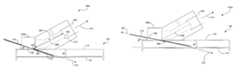
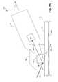
- FIG. 4is a schematic diagram of a coupler embodiment, coupler 102 a , similar to that shown in FIG. 3 , and that illustrates application of a sound beam and receiving a needle along an axis that is parallel to and offset from a sound beam axis.
- a transducer element 402 of the transducer assembly 104( FIG. 1 ) is disposed conformably (although any well-known attachment/detachment mechanisms may be employed) in the housing portion 310 and secured enough to assure proper alignment between the transducer assembly 104 and the coupler 102 a .
- the transducer element 402has a concave surface 404 to provide a focused sound beam. The focused beam could also be achieved using an acoustic lens.
- the transducer element 402is disposed at a distance (represented by the line labeled “A” in FIG. 4 ) of approximately 4 cm from the location 406 on the reflective surface on which a sound beam 408 (shown herein as the centerline of the beam, with the understanding that a larger sound profile is preferably radiated) impinges to the point on the convex surface 404 farthest from said location 406 .
- This 4 cm distanceenables a 1 mm diameter sound beam focal region to begin at the skin surface. Note that this dimension “A” may vary in some embodiments, depending on the characteristics of the sound beam from the focused transducer element 402 .
- “A”can be determined mathematically according to known formulas, and/or determined (or verified) experimentally.
- the transducer element 402is disposed in the housing portion 310 at a suitable distance to accommodate a focal length of approximately 5 cm, in such a way that the focal region begins at the surface of the skin 112 , which enables detection of a vein along a longer range.
- a focal length of approximately 5 cmin such a way that the focal region begins at the surface of the skin 112 , which enables detection of a vein along a longer range.
- experimentation and mathematical analysishave indicated that the focal region for a sound field produced by a 1 centimeter (cm) diameter, 10 MHz transducer with a focal length of 5 cm is ellipsoidal, about 1 mm in diameter, and more than 2 cm long. In other words, there exists a “beam-like” quality of the sound field within ⁇ 1 cm of the focal point.
- the sound beam 408is radiated in the chamber 306 along an axis that is coincident with a first axis 410 .
- the chamber 306includes a coupling material (not shown) that provides an appropriate low loss impedance matched propagation medium for the sound beam 408 when entering the interior of the body 106 and returning from the interior of the body 106 .
- the sound beam 408impinges on the reflective portion 304 a at location 406 and is reflected along an axis coincident with a second axis 412 .
- the angle ⁇ between the reflected sound beam along the second axis 412 and the skin surface 112is approximately 30°, although other angles may be used.
- the reflected sound beam 408is transmitted through the skin surface 112 and impinges on the vein 114 , and then at least a portion of the beam is reflected back to the transducer element 402 along the second axis 412 , and then the first axis 410 after reflection at 406 of the reflective portion 304 a .
- the transducer element 402converts the received sound beam 408 to an electronic signal that is processed in the receive electronics (e.g., 208 , 210 of FIG. 2 ) of the transducer assembly 104 to elicit a feedback response by the output module 212 ( FIG. 2 ).
- a feedback responseprovides an indication that a vein has been located, and in some embodiments, an indication of the signal strength corresponding to whether the vein has been located at a position offset from the centerline of the vein (where blood flow may be slower) or at the centerline (where blood flow is greatest).
- the usercan insert the needle 110 through the guideway 108 .
- the guideway 108is oriented parallel to the second axis 412 , offset a fixed and constant distance (e.g., 0 to 5 mm) from the second axis 412 .
- the inserted needle 110interferes minimally with the sound field present beneath the skin surface 112 , and enables the user to continually monitor the location of the vein 114 as the needle is advanced, up until the time corresponding to when the vein 114 is punctured.
- the angle ⁇which is the angle formed between the guideway 108 and the skin surface 112 , is approximately 30°, although other angles may be used.
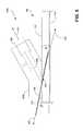
- FIG. 5is a schematic diagram of another coupler embodiment, coupler 102 b , that illustrates application of the sound beam 408 and receiving the needle 110 along an axis 502 that has a depth dependent offset relative to a sound beam axis 412 .
- the coupler 102 bhas similar components to those found in couplers 102 , 102 a of FIGS. 3 and 4 , respectively, and thus discussion of the same will be omitted or abbreviated.
- the sound beam 408is radiated from the transducer element 402 along the first axis 410 , reflected off a reflective portion 304 b , and provided along the second axis 412 to impinge on the vein 114 .
- the angle ⁇is approximately 30°, although other angles may be used.
- the guideway 108(and also the bottom surface of the reflective portion 304 b in one embodiment) form an angle ⁇ of approximately 23°, although other angles may be used.
- the needle 110is advanced along the guideway 108 along a third axis 502 , resulting in the needle 110 intersecting the sound beam 408 provided along the second axis 412 in a location proximally (i.e., the axis 502 intersecting axis 402 in a location approximately at the point where the focal region ends, such as where the beam width ceases to be 1 mm in diameter in embodiments described herein) to the vein 114 .
- the offsetwill vary based on the depth of the vein 114 .
- FIG. 6is a front-view schematic diagram of the needle insertion system 100 shown in FIG. 1 that illustrates traversing the skin surface 112 to obtain a strong signal indicating location of the vein 114 and/or optimal locations along the vein 114 .
- the needle insertion system 100is shown traversing across the skin surface, but it also is traversable in the direction running along the length of the body 106 , as well as rotatably traversable.
- the needle insertion system 100is moved (represented by the double-arrow head above the system 100 ) across the skin surface 112 until the vein 114 is detected.
- Vein detectionand/or location
- the sound beam reflection from the vein 114enables the needle 110 (or an IV catheter, for example, in some implementations) to be aligned, but offset, with the sound beam 408 .
- the sound beam 408is known (using Doppler technology) to be passing through a suitable vein 114 .
- the needleis advanced through the guideway 108 a (parallel to, but offset from the sound beam 408 in this implementation), passing through the skin surface 112 and advanced until it punctures the vein 114 .
- the usercontinually receives feedback that he or she is advancing the needle 110 in the right direction until the vein 114 is punctured.
- FIG. 7Ais a schematic diagram that illustrates another embodiment of a needle insertion system 700 .
- the needle insertion system 700differs from the prior described embodiments in that a needle is advanced to a vein along an axis that is coincident with the sound beam.
- the needle insertion system 700includes a transducer assembly 704 attached to the coupler 702 .
- the transducer 704is attachable and detachable from the coupler 702 (e.g., shown here as rotatably attachable and detachable).
- the transducer assembly 704includes the same or similar electronics to the transducer assembly 104 shown in FIG. 2 , and thus illustration and discussion of the same is omitted.
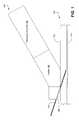
- FIG. 7Bis a side-view cut-away of an embodiment of the coupler 702 of the needle insertion system 700 shown in FIG. 7A .
- the coupler 702is preferably made of plastic, and comprises membranes 706 and 708 and a chamber 710 that includes an ultrasonic coupling material (not shown).
- Membranes 706 and 708may be made of, for example, rubber.
- the coupling materialcan be, for example, a sterile, de-aerated saline.
- the coupler 702may be disposable, and included with the needle 110 in a plastic package (not shown) designed to maintain the sterility of the coupler 702 and the needle 110 .
- the coupler 702can be designed to split in half to allow removal of the coupler 702 after the vein 110 has been punctured, an unnecessary step for simply drawing blood.
- the membranes 706 and 708are traversed by the needle 110 during the insertion, the needle 110 being advanced through the guideway 712 .
- the membrane 706is also an ultrasound reflector.
- the membrane 706is air-backed and preferably as smooth and flat as possible.
- the membrane 708serves to couple the sound beam 408 into the tissue of the body 106 .
- an ultrasonic coupling gel(not shown) may be applied to the outside surface of the membrane 708 (i.e., the surface contacting the skin surface 112 ).
- the transducer element 402 of the transducer assembly 704radiates the sound beam 408 a distance (represented by the line labeled “B”) of approximately 4 cm to the membrane 706 in similar manner to that described in association with FIG. 4 .
- the sound beamis radiated along a first axis 410 .
- the sound beam 408is reflected by the air-backed membrane 706 before entering the body 106 through the membrane 708 .
- the reflected sound beam 408travels along the second axis 412 .
- the travel path and orientation of the reflected sound beam 408enables the needle 110 (or an IV catheter) to be exactly aligned or substantially aligned with the reflected sound beam 408 , which is known by Doppler to be passing through a suitable vein 114 .
- the sound beam 408is shown to make an angle ⁇ of 30° relative to the plane of the skin surface 112 , it would be understood by one having ordinary skill in the art that some embodiments may utilize one of a variety of different angles (e.g., 45° or 20°) depending on the application.
- the needle 110is advanced (not shown) through the guideway 712 , which is coincident (or coaxial) with the sound beam 408 .
- the needle 110is advanced through the membrane 706 , through the chamber 710 (and thus through a coupling material not shown, such as saline fluid), and then through the membrane 708 , and continually (still along the second axis 412 ) advanced until the needle 110 punctures the vein 114 .
- the coaxial alignment of the guideway 712 and sound beamassures (or assures with a high-probability of certainty) that the needle 110 will encounter the vein 114 .
- the coupler 702in one embodiment, can then be easily disassembled into two or more pieces and removed, and the IV cauterization or blood draw can be completed.
- the saline filled chamber 710can be replaced with a solid insert (not shown), which can be removed after the vein 114 is detected to allow passage of the needle 110 .
- the membranes 706 and 708may be omitted and the user can view the insertion point.
- a needle insertion method 800may comprise, as illustrated in FIG. 8 , transmitting a sound beam along an axis to contact a blood vessel ( 802 ); receiving the reflected sound beam from the blood vessel ( 804 ); processing the reflected sound beam to detect the location of the blood vessel ( 806 ); and, responsive to the detection, receiving a needle in a guideway that is oriented parallel to the axis ( 808 ).
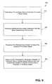
- FIG. 9Another embodiment of a needle insertion method 900 may comprise, as illustrated in FIG. 9 , transmitting a sound beam along a first axis to contact a blood vessel ( 902 ); receiving a reflected sound beam reflected from the blood vessel along the first axis ( 904 ); processing the reflected sound beam to detect the location of the blood vessel ( 906 ); and, responsive to the detection, receiving a needle in a guideway that is oriented along a second axis that enables the needle to intersect the first axis in proximity to the blood vessel ( 908 ).
Landscapes
- Health & Medical Sciences (AREA)
- Life Sciences & Earth Sciences (AREA)
- Physics & Mathematics (AREA)
- Heart & Thoracic Surgery (AREA)
- Molecular Biology (AREA)
- Nuclear Medicine, Radiotherapy & Molecular Imaging (AREA)
- Pathology (AREA)
- Radiology & Medical Imaging (AREA)
- Engineering & Computer Science (AREA)
- Biomedical Technology (AREA)
- Veterinary Medicine (AREA)
- Medical Informatics (AREA)
- Biophysics (AREA)
- Surgery (AREA)
- Animal Behavior & Ethology (AREA)
- General Health & Medical Sciences (AREA)
- Public Health (AREA)
- Hematology (AREA)
- Acoustics & Sound (AREA)
- Ultra Sonic Daignosis Equipment (AREA)
- Infusion, Injection, And Reservoir Apparatuses (AREA)
Abstract
Description
where f is the transmitted frequency (e.g., 10 Mega-Hertz (MHz)), c is the speed of sound in the tissue (approximately 1500 meters per second (m/sec)) and θ is the angle between the flow velocity direction and the sound beam axis. For a typical vein, the flow velocity is of the order of 10 cm/sec. If θ is, for example, 30°, the frequency shift will be 667 Hz. Such shifts can be detected by “beating” the received signal against the transmitted signal. The presence of an audio frequency beat signal in the output (in this case at 667 Hz) indicates a Doppler shift, and hence that the beam is intersecting a blood vessel such as an artery or vein. Since arterial flow is away from the heart and venous flow is towards the heart, the distinction between arteries and veins is made by determining whether the Doppler shift is positive or negative. Both the size of the Doppler shift and the strength of the Doppler shifted signals are helpful in selecting the most suitable vein since a larger vein has higher flow velocities in addition to being a better scatterer.
Claims (22)
Priority Applications (2)
| Application Number | Priority Date | Filing Date | Title |
|---|---|---|---|
| US10/897,663US7766839B2 (en) | 2003-07-22 | 2004-07-22 | Needle insertion systems and methods |
| US12/823,005US20100298702A1 (en) | 2003-07-22 | 2010-06-24 | Needle insertion systems and methods |
Applications Claiming Priority (2)
| Application Number | Priority Date | Filing Date | Title |
|---|---|---|---|
| US48912503P | 2003-07-22 | 2003-07-22 | |
| US10/897,663US7766839B2 (en) | 2003-07-22 | 2004-07-22 | Needle insertion systems and methods |
Related Child Applications (1)
| Application Number | Title | Priority Date | Filing Date |
|---|---|---|---|
| US12/823,005DivisionUS20100298702A1 (en) | 2003-07-22 | 2010-06-24 | Needle insertion systems and methods |
Publications (2)
| Publication Number | Publication Date |
|---|---|
| US20050033177A1 US20050033177A1 (en) | 2005-02-10 |
| US7766839B2true US7766839B2 (en) | 2010-08-03 |
Family
ID=34102826
Family Applications (2)
| Application Number | Title | Priority Date | Filing Date |
|---|---|---|---|
| US10/897,663Expired - Fee RelatedUS7766839B2 (en) | 2003-07-22 | 2004-07-22 | Needle insertion systems and methods |
| US12/823,005AbandonedUS20100298702A1 (en) | 2003-07-22 | 2010-06-24 | Needle insertion systems and methods |
Family Applications After (1)
| Application Number | Title | Priority Date | Filing Date |
|---|---|---|---|
| US12/823,005AbandonedUS20100298702A1 (en) | 2003-07-22 | 2010-06-24 | Needle insertion systems and methods |
Country Status (2)
| Country | Link |
|---|---|
| US (2) | US7766839B2 (en) |
| WO (1) | WO2005009509A2 (en) |
Cited By (43)
| Publication number | Priority date | Publication date | Assignee | Title |
|---|---|---|---|---|
| US20110071394A1 (en)* | 2009-09-23 | 2011-03-24 | Fedinec James J | Central venous catheter kit with line gripping and needle localizing devices |
| US8388541B2 (en) | 2007-11-26 | 2013-03-05 | C. R. Bard, Inc. | Integrated system for intravascular placement of a catheter |
| US8388546B2 (en) | 2006-10-23 | 2013-03-05 | Bard Access Systems, Inc. | Method of locating the tip of a central venous catheter |
| US8437833B2 (en) | 2008-10-07 | 2013-05-07 | Bard Access Systems, Inc. | Percutaneous magnetic gastrostomy |
| US8478382B2 (en) | 2008-02-11 | 2013-07-02 | C. R. Bard, Inc. | Systems and methods for positioning a catheter |
| US8512256B2 (en) | 2006-10-23 | 2013-08-20 | Bard Access Systems, Inc. | Method of locating the tip of a central venous catheter |
| USD699359S1 (en) | 2011-08-09 | 2014-02-11 | C. R. Bard, Inc. | Ultrasound probe head |
| US8781555B2 (en) | 2007-11-26 | 2014-07-15 | C. R. Bard, Inc. | System for placement of a catheter including a signal-generating stylet |
| US8784336B2 (en) | 2005-08-24 | 2014-07-22 | C. R. Bard, Inc. | Stylet apparatuses and methods of manufacture |
| US8801693B2 (en) | 2010-10-29 | 2014-08-12 | C. R. Bard, Inc. | Bioimpedance-assisted placement of a medical device |
| US8849382B2 (en) | 2007-11-26 | 2014-09-30 | C. R. Bard, Inc. | Apparatus and display methods relating to intravascular placement of a catheter |
| US8945011B2 (en) | 2011-04-05 | 2015-02-03 | Houston Medical Robotics, Inc. | Systems and methods for accessing the lumen of a vessel |
| USD724745S1 (en) | 2011-08-09 | 2015-03-17 | C. R. Bard, Inc. | Cap for an ultrasound probe |
| US9033880B2 (en) | 2011-04-05 | 2015-05-19 | Houston Medical Robotics, Inc. | Robotic insertion systems and methods |
| US9125578B2 (en) | 2009-06-12 | 2015-09-08 | Bard Access Systems, Inc. | Apparatus and method for catheter navigation and tip location |
| US9211107B2 (en) | 2011-11-07 | 2015-12-15 | C. R. Bard, Inc. | Ruggedized ultrasound hydrogel insert |
| US9339206B2 (en) | 2009-06-12 | 2016-05-17 | Bard Access Systems, Inc. | Adaptor for endovascular electrocardiography |
| US9445734B2 (en) | 2009-06-12 | 2016-09-20 | Bard Access Systems, Inc. | Devices and methods for endovascular electrography |
| US9456766B2 (en) | 2007-11-26 | 2016-10-04 | C. R. Bard, Inc. | Apparatus for use with needle insertion guidance system |
| US9492097B2 (en) | 2007-11-26 | 2016-11-15 | C. R. Bard, Inc. | Needle length determination and calibration for insertion guidance system |
| US9521961B2 (en) | 2007-11-26 | 2016-12-20 | C. R. Bard, Inc. | Systems and methods for guiding a medical instrument |
| US9532724B2 (en) | 2009-06-12 | 2017-01-03 | Bard Access Systems, Inc. | Apparatus and method for catheter navigation using endovascular energy mapping |
| US9554716B2 (en) | 2007-11-26 | 2017-01-31 | C. R. Bard, Inc. | Insertion guidance system for needles and medical components |
| US9636031B2 (en) | 2007-11-26 | 2017-05-02 | C.R. Bard, Inc. | Stylets for use with apparatus for intravascular placement of a catheter |
| US9649048B2 (en) | 2007-11-26 | 2017-05-16 | C. R. Bard, Inc. | Systems and methods for breaching a sterile field for intravascular placement of a catheter |
| US9839372B2 (en) | 2014-02-06 | 2017-12-12 | C. R. Bard, Inc. | Systems and methods for guidance and placement of an intravascular device |
| US9861739B2 (en) | 2011-04-05 | 2018-01-09 | Houston Medical Robotics, Inc. | Systems and methods for accessing the lumen of a vessel |
| US9901714B2 (en) | 2008-08-22 | 2018-02-27 | C. R. Bard, Inc. | Catheter assembly including ECG sensor and magnetic assemblies |
| US10046139B2 (en) | 2010-08-20 | 2018-08-14 | C. R. Bard, Inc. | Reconfirmation of ECG-assisted catheter tip placement |
| US10123766B2 (en) | 2011-12-08 | 2018-11-13 | University Of Washington Through Its Center For Commercialization | Ultrasound stylet |
| US10349890B2 (en) | 2015-06-26 | 2019-07-16 | C. R. Bard, Inc. | Connector interface for ECG-based catheter positioning system |
| US10449330B2 (en) | 2007-11-26 | 2019-10-22 | C. R. Bard, Inc. | Magnetic element-equipped needle assemblies |
| US10524691B2 (en) | 2007-11-26 | 2020-01-07 | C. R. Bard, Inc. | Needle assembly including an aligned magnetic element |
| US10639008B2 (en) | 2009-10-08 | 2020-05-05 | C. R. Bard, Inc. | Support and cover structures for an ultrasound probe head |
| US10751509B2 (en) | 2007-11-26 | 2020-08-25 | C. R. Bard, Inc. | Iconic representations for guidance of an indwelling medical device |
| US10820885B2 (en) | 2012-06-15 | 2020-11-03 | C. R. Bard, Inc. | Apparatus and methods for detection of a removable cap on an ultrasound probe |
| US10973584B2 (en) | 2015-01-19 | 2021-04-13 | Bard Access Systems, Inc. | Device and method for vascular access |
| US10992079B2 (en) | 2018-10-16 | 2021-04-27 | Bard Access Systems, Inc. | Safety-equipped connection systems and methods thereof for establishing electrical connections |
| US11000207B2 (en) | 2016-01-29 | 2021-05-11 | C. R. Bard, Inc. | Multiple coil system for tracking a medical device |
| US11103213B2 (en) | 2009-10-08 | 2021-08-31 | C. R. Bard, Inc. | Spacers for use with an ultrasound probe |
| US11723687B2 (en) | 2019-12-11 | 2023-08-15 | Medline Industries, Lp | Window dressing for use with ultrasonic aid in venipuncture |
| US11918795B2 (en) | 2019-05-01 | 2024-03-05 | Bard Access Systems, Inc. | Puncturing devices, puncturing systems including the puncturing devices, and methods thereof |
| US12303324B2 (en) | 2018-05-31 | 2025-05-20 | Faction Imaging Inc. | Method of medical imaging using multiple arrays |
Families Citing this family (23)
| Publication number | Priority date | Publication date | Assignee | Title |
|---|---|---|---|---|
| US8309428B2 (en) | 2004-09-15 | 2012-11-13 | Sonetics Ultrasound, Inc. | Capacitive micromachined ultrasonic transducer |
| US7888709B2 (en) | 2004-09-15 | 2011-02-15 | Sonetics Ultrasound, Inc. | Capacitive micromachined ultrasonic transducer and manufacturing method |
| US8658453B2 (en)* | 2004-09-15 | 2014-02-25 | Sonetics Ultrasound, Inc. | Capacitive micromachined ultrasonic transducer |
| WO2006064433A2 (en)* | 2004-12-13 | 2006-06-22 | Koninklijke Philips Electronics N.V. | Cannula inserting system |
| US20070038088A1 (en)* | 2005-08-04 | 2007-02-15 | Rich Collin A | Medical imaging user interface and control scheme |
| US8939911B2 (en)* | 2006-01-25 | 2015-01-27 | Kabushiki Kaisha Toshiba | Ultrasonic probe and apparatus for obtaining ultrasonic image |
| US20080071149A1 (en)* | 2006-09-20 | 2008-03-20 | Collin Rich | Method and system of representing a medical event |
| US20080071292A1 (en)* | 2006-09-20 | 2008-03-20 | Rich Collin A | System and method for displaying the trajectory of an instrument and the position of a body within a volume |
| DE102007025132B4 (en)* | 2007-05-30 | 2014-09-11 | Rolf Elliger | vein Finder |
| US20100010505A1 (en)* | 2008-07-11 | 2010-01-14 | Herlihy J Patrick | Methods and apparatus for introducing a medical device into the body of a patient |
| US8315125B2 (en)* | 2009-03-18 | 2012-11-20 | Sonetics Ultrasound, Inc. | System and method for biasing CMUT elements |
| US8655143B2 (en)* | 2009-04-01 | 2014-02-18 | Cisco Technology, Inc. | Supplementary buffer construction in real-time applications without increasing channel change delay |
| US8731000B2 (en)* | 2009-09-30 | 2014-05-20 | Cisco Technology, Inc. | Decoding earlier frames with DTS/PTS backward extrapolation |
| US8761862B2 (en)* | 2009-10-09 | 2014-06-24 | Stephen F. Ridley | Ultrasound guided probe device and sterilizable shield for same |
| TWI541037B (en) | 2009-10-30 | 2016-07-11 | 國立陽明大學 | An puncture positioning apparatus for epidural space |
| US8914244B2 (en)* | 2010-08-04 | 2014-12-16 | The Boeing Company | Apparatus and method for inspecting laminated structure |
| US20130041250A1 (en)* | 2011-08-09 | 2013-02-14 | Ultrasonix Medical Corporation | Methods and apparatus for locating arteries and veins using ultrasound |
| US20140330087A1 (en)* | 2013-05-01 | 2014-11-06 | Medsensation, Inc. | Devices and methods for obtaining physiological data |
| KR20150005052A (en)* | 2013-07-04 | 2015-01-14 | 삼성메디슨 주식회사 | Ultrasound system and method for providing target object information |
| DE102013218001B4 (en)* | 2013-09-09 | 2015-04-02 | Continental Automotive Gmbh | Ultrasonic sensor with deflection element |
| WO2016069862A1 (en) | 2014-10-29 | 2016-05-06 | Zoll Medical Corporation | Measuring myocardial physiologic parameters |
| WO2017027789A1 (en) | 2015-08-12 | 2017-02-16 | Sonectics Ultrasound, Inc. | Method and system for measuring pressure using ultrasound |
| US11432801B2 (en) | 2017-04-06 | 2022-09-06 | Duke University | Interventional ultrasound probe |
Citations (15)
| Publication number | Priority date | Publication date | Assignee | Title |
|---|---|---|---|---|
| US3556079A (en) | 1967-05-16 | 1971-01-19 | Haruo Omizo | Method of puncturing a medical instrument under guidance of ultrasound |
| US4325381A (en)* | 1979-11-21 | 1982-04-20 | New York Institute Of Technology | Ultrasonic scanning head with reduced geometrical distortion |
| US4527569A (en) | 1982-11-26 | 1985-07-09 | South African Inventions Develop. Corp. | Device for guiding a surgical needle into a blood vessel |
| US4667679A (en) | 1982-08-12 | 1987-05-26 | Harvinder Sahota | Apparatus and method for positioning and puncturing an artery and a vein |
| US4742829A (en)* | 1986-08-11 | 1988-05-10 | General Electric Company | Intracavitary ultrasound and biopsy probe for transvaginal imaging |
| US4887606A (en) | 1986-09-18 | 1989-12-19 | Yock Paul G | Apparatus for use in cannulation of blood vessels |
| US5080103A (en) | 1989-03-21 | 1992-01-14 | Isotopen-Technik Dr. Sauerwein Gmbh | Syringe for doppler sonographically aided penetration |
| US5103825A (en) | 1991-03-05 | 1992-04-14 | D. E. Hokanson, Inc. | Doppler transducer probe with direction indicator |
| US5131395A (en) | 1990-03-28 | 1992-07-21 | Gehlbach Steve M | Ultrasonic apparatus for guiding needles into surface vessels |
| US5167630A (en) | 1991-09-26 | 1992-12-01 | Paul Kamaljit S | Blood vessel cannulation device |
| US5309915A (en) | 1993-06-07 | 1994-05-10 | Mte, Inc. | Apparatus for locating veins and arteries |
| US5427108A (en)* | 1993-04-01 | 1995-06-27 | Bollinger; Armin | Ultrasonic Doppler probe with needle guide |
| US6056692A (en) | 1998-07-08 | 2000-05-02 | Schwartz; John Q. | Apparatus and method for locating and marking blood vessels |
| US6132379A (en)* | 1998-11-04 | 2000-10-17 | Patacsil; Estelito G. | Method and apparatus for ultrasound guided intravenous cannulation |
| US6379307B1 (en) | 1998-09-16 | 2002-04-30 | Roy Filly | Adjustable needle guide apparatus and method |
Family Cites Families (4)
| Publication number | Priority date | Publication date | Assignee | Title |
|---|---|---|---|---|
| US5261409A (en)* | 1991-05-27 | 1993-11-16 | Sulzer Brothers Limited | Puncturing device for blood vessels |
| JPH06213660A (en)* | 1993-01-19 | 1994-08-05 | Aisin Seiki Co Ltd | Detecting method for approximate straight line of image |
| US6417133B1 (en)* | 1998-02-25 | 2002-07-09 | Monsanto Technology Llc | Deeply reduced oxidation catalyst and its use for catalyzing liquid phase oxidation reactions |
| AUPQ175399A0 (en)* | 1999-07-21 | 1999-08-12 | Carlton And United Breweries Limited | Soil conditioner and fertilizer |
- 2004
- 2004-07-22USUS10/897,663patent/US7766839B2/ennot_activeExpired - Fee Related
- 2004-07-22WOPCT/US2004/023521patent/WO2005009509A2/enactiveApplication Filing
- 2010
- 2010-06-24USUS12/823,005patent/US20100298702A1/ennot_activeAbandoned
Patent Citations (15)
| Publication number | Priority date | Publication date | Assignee | Title |
|---|---|---|---|---|
| US3556079A (en) | 1967-05-16 | 1971-01-19 | Haruo Omizo | Method of puncturing a medical instrument under guidance of ultrasound |
| US4325381A (en)* | 1979-11-21 | 1982-04-20 | New York Institute Of Technology | Ultrasonic scanning head with reduced geometrical distortion |
| US4667679A (en) | 1982-08-12 | 1987-05-26 | Harvinder Sahota | Apparatus and method for positioning and puncturing an artery and a vein |
| US4527569A (en) | 1982-11-26 | 1985-07-09 | South African Inventions Develop. Corp. | Device for guiding a surgical needle into a blood vessel |
| US4742829A (en)* | 1986-08-11 | 1988-05-10 | General Electric Company | Intracavitary ultrasound and biopsy probe for transvaginal imaging |
| US4887606A (en) | 1986-09-18 | 1989-12-19 | Yock Paul G | Apparatus for use in cannulation of blood vessels |
| US5080103A (en) | 1989-03-21 | 1992-01-14 | Isotopen-Technik Dr. Sauerwein Gmbh | Syringe for doppler sonographically aided penetration |
| US5131395A (en) | 1990-03-28 | 1992-07-21 | Gehlbach Steve M | Ultrasonic apparatus for guiding needles into surface vessels |
| US5103825A (en) | 1991-03-05 | 1992-04-14 | D. E. Hokanson, Inc. | Doppler transducer probe with direction indicator |
| US5167630A (en) | 1991-09-26 | 1992-12-01 | Paul Kamaljit S | Blood vessel cannulation device |
| US5427108A (en)* | 1993-04-01 | 1995-06-27 | Bollinger; Armin | Ultrasonic Doppler probe with needle guide |
| US5309915A (en) | 1993-06-07 | 1994-05-10 | Mte, Inc. | Apparatus for locating veins and arteries |
| US6056692A (en) | 1998-07-08 | 2000-05-02 | Schwartz; John Q. | Apparatus and method for locating and marking blood vessels |
| US6379307B1 (en) | 1998-09-16 | 2002-04-30 | Roy Filly | Adjustable needle guide apparatus and method |
| US6132379A (en)* | 1998-11-04 | 2000-10-17 | Patacsil; Estelito G. | Method and apparatus for ultrasound guided intravenous cannulation |
Non-Patent Citations (1)
| Title |
|---|
| Peter H. Rogers, David H. Trivett, Michael D. Gray, James W. Larsen, Invention Disclosure for A Device for Locating Veins and Aligning and Inserting Intravenous Catheters and Blood Drawing Needles Therein, Jul. 17, 2003, Georgia Institute of Technology, Atlanta, GA 30328. |
Cited By (82)
| Publication number | Priority date | Publication date | Assignee | Title |
|---|---|---|---|---|
| US8784336B2 (en) | 2005-08-24 | 2014-07-22 | C. R. Bard, Inc. | Stylet apparatuses and methods of manufacture |
| US10004875B2 (en) | 2005-08-24 | 2018-06-26 | C. R. Bard, Inc. | Stylet apparatuses and methods of manufacture |
| US11207496B2 (en) | 2005-08-24 | 2021-12-28 | C. R. Bard, Inc. | Stylet apparatuses and methods of manufacture |
| US9833169B2 (en) | 2006-10-23 | 2017-12-05 | Bard Access Systems, Inc. | Method of locating the tip of a central venous catheter |
| US8388546B2 (en) | 2006-10-23 | 2013-03-05 | Bard Access Systems, Inc. | Method of locating the tip of a central venous catheter |
| US9345422B2 (en) | 2006-10-23 | 2016-05-24 | Bard Acess Systems, Inc. | Method of locating the tip of a central venous catheter |
| US9265443B2 (en) | 2006-10-23 | 2016-02-23 | Bard Access Systems, Inc. | Method of locating the tip of a central venous catheter |
| US8512256B2 (en) | 2006-10-23 | 2013-08-20 | Bard Access Systems, Inc. | Method of locating the tip of a central venous catheter |
| US8774907B2 (en) | 2006-10-23 | 2014-07-08 | Bard Access Systems, Inc. | Method of locating the tip of a central venous catheter |
| US8858455B2 (en) | 2006-10-23 | 2014-10-14 | Bard Access Systems, Inc. | Method of locating the tip of a central venous catheter |
| US10751509B2 (en) | 2007-11-26 | 2020-08-25 | C. R. Bard, Inc. | Iconic representations for guidance of an indwelling medical device |
| US9492097B2 (en) | 2007-11-26 | 2016-11-15 | C. R. Bard, Inc. | Needle length determination and calibration for insertion guidance system |
| US8849382B2 (en) | 2007-11-26 | 2014-09-30 | C. R. Bard, Inc. | Apparatus and display methods relating to intravascular placement of a catheter |
| US8781555B2 (en) | 2007-11-26 | 2014-07-15 | C. R. Bard, Inc. | System for placement of a catheter including a signal-generating stylet |
| US11707205B2 (en) | 2007-11-26 | 2023-07-25 | C. R. Bard, Inc. | Integrated system for intravascular placement of a catheter |
| US10105121B2 (en) | 2007-11-26 | 2018-10-23 | C. R. Bard, Inc. | System for placement of a catheter including a signal-generating stylet |
| US11134915B2 (en) | 2007-11-26 | 2021-10-05 | C. R. Bard, Inc. | System for placement of a catheter including a signal-generating stylet |
| US11123099B2 (en) | 2007-11-26 | 2021-09-21 | C. R. Bard, Inc. | Apparatus for use with needle insertion guidance system |
| US10231753B2 (en) | 2007-11-26 | 2019-03-19 | C. R. Bard, Inc. | Insertion guidance system for needles and medical components |
| US10966630B2 (en) | 2007-11-26 | 2021-04-06 | C. R. Bard, Inc. | Integrated system for intravascular placement of a catheter |
| US11779240B2 (en) | 2007-11-26 | 2023-10-10 | C. R. Bard, Inc. | Systems and methods for breaching a sterile field for intravascular placement of a catheter |
| US10849695B2 (en) | 2007-11-26 | 2020-12-01 | C. R. Bard, Inc. | Systems and methods for breaching a sterile field for intravascular placement of a catheter |
| US10165962B2 (en) | 2007-11-26 | 2019-01-01 | C. R. Bard, Inc. | Integrated systems for intravascular placement of a catheter |
| US9999371B2 (en) | 2007-11-26 | 2018-06-19 | C. R. Bard, Inc. | Integrated system for intravascular placement of a catheter |
| US10602958B2 (en) | 2007-11-26 | 2020-03-31 | C. R. Bard, Inc. | Systems and methods for guiding a medical instrument |
| US10524691B2 (en) | 2007-11-26 | 2020-01-07 | C. R. Bard, Inc. | Needle assembly including an aligned magnetic element |
| US9456766B2 (en) | 2007-11-26 | 2016-10-04 | C. R. Bard, Inc. | Apparatus for use with needle insertion guidance system |
| US11529070B2 (en) | 2007-11-26 | 2022-12-20 | C. R. Bard, Inc. | System and methods for guiding a medical instrument |
| US9521961B2 (en) | 2007-11-26 | 2016-12-20 | C. R. Bard, Inc. | Systems and methods for guiding a medical instrument |
| US9526440B2 (en) | 2007-11-26 | 2016-12-27 | C.R. Bard, Inc. | System for placement of a catheter including a signal-generating stylet |
| US10449330B2 (en) | 2007-11-26 | 2019-10-22 | C. R. Bard, Inc. | Magnetic element-equipped needle assemblies |
| US9549685B2 (en) | 2007-11-26 | 2017-01-24 | C. R. Bard, Inc. | Apparatus and display methods relating to intravascular placement of a catheter |
| US9554716B2 (en) | 2007-11-26 | 2017-01-31 | C. R. Bard, Inc. | Insertion guidance system for needles and medical components |
| US9636031B2 (en) | 2007-11-26 | 2017-05-02 | C.R. Bard, Inc. | Stylets for use with apparatus for intravascular placement of a catheter |
| US9649048B2 (en) | 2007-11-26 | 2017-05-16 | C. R. Bard, Inc. | Systems and methods for breaching a sterile field for intravascular placement of a catheter |
| US9681823B2 (en) | 2007-11-26 | 2017-06-20 | C. R. Bard, Inc. | Integrated system for intravascular placement of a catheter |
| US8388541B2 (en) | 2007-11-26 | 2013-03-05 | C. R. Bard, Inc. | Integrated system for intravascular placement of a catheter |
| US10342575B2 (en) | 2007-11-26 | 2019-07-09 | C. R. Bard, Inc. | Apparatus for use with needle insertion guidance system |
| US10238418B2 (en) | 2007-11-26 | 2019-03-26 | C. R. Bard, Inc. | Apparatus for use with needle insertion guidance system |
| US8478382B2 (en) | 2008-02-11 | 2013-07-02 | C. R. Bard, Inc. | Systems and methods for positioning a catheter |
| US8971994B2 (en) | 2008-02-11 | 2015-03-03 | C. R. Bard, Inc. | Systems and methods for positioning a catheter |
| US9901714B2 (en) | 2008-08-22 | 2018-02-27 | C. R. Bard, Inc. | Catheter assembly including ECG sensor and magnetic assemblies |
| US11027101B2 (en) | 2008-08-22 | 2021-06-08 | C. R. Bard, Inc. | Catheter assembly including ECG sensor and magnetic assemblies |
| US9907513B2 (en) | 2008-10-07 | 2018-03-06 | Bard Access Systems, Inc. | Percutaneous magnetic gastrostomy |
| US8437833B2 (en) | 2008-10-07 | 2013-05-07 | Bard Access Systems, Inc. | Percutaneous magnetic gastrostomy |
| US10912488B2 (en) | 2009-06-12 | 2021-02-09 | Bard Access Systems, Inc. | Apparatus and method for catheter navigation and tip location |
| US9339206B2 (en) | 2009-06-12 | 2016-05-17 | Bard Access Systems, Inc. | Adaptor for endovascular electrocardiography |
| US10231643B2 (en) | 2009-06-12 | 2019-03-19 | Bard Access Systems, Inc. | Apparatus and method for catheter navigation and tip location |
| US9125578B2 (en) | 2009-06-12 | 2015-09-08 | Bard Access Systems, Inc. | Apparatus and method for catheter navigation and tip location |
| US10271762B2 (en) | 2009-06-12 | 2019-04-30 | Bard Access Systems, Inc. | Apparatus and method for catheter navigation using endovascular energy mapping |
| US11419517B2 (en) | 2009-06-12 | 2022-08-23 | Bard Access Systems, Inc. | Apparatus and method for catheter navigation using endovascular energy mapping |
| US9532724B2 (en) | 2009-06-12 | 2017-01-03 | Bard Access Systems, Inc. | Apparatus and method for catheter navigation using endovascular energy mapping |
| US9445734B2 (en) | 2009-06-12 | 2016-09-20 | Bard Access Systems, Inc. | Devices and methods for endovascular electrography |
| US20110071394A1 (en)* | 2009-09-23 | 2011-03-24 | Fedinec James J | Central venous catheter kit with line gripping and needle localizing devices |
| US8277417B2 (en)* | 2009-09-23 | 2012-10-02 | James J. Fedinec | Central venous catheter kit with line gripping and needle localizing devices |
| US11998386B2 (en) | 2009-10-08 | 2024-06-04 | C. R. Bard, Inc. | Support and cover structures for an ultrasound probe head |
| US10639008B2 (en) | 2009-10-08 | 2020-05-05 | C. R. Bard, Inc. | Support and cover structures for an ultrasound probe head |
| US11103213B2 (en) | 2009-10-08 | 2021-08-31 | C. R. Bard, Inc. | Spacers for use with an ultrasound probe |
| US10046139B2 (en) | 2010-08-20 | 2018-08-14 | C. R. Bard, Inc. | Reconfirmation of ECG-assisted catheter tip placement |
| US8801693B2 (en) | 2010-10-29 | 2014-08-12 | C. R. Bard, Inc. | Bioimpedance-assisted placement of a medical device |
| US9415188B2 (en) | 2010-10-29 | 2016-08-16 | C. R. Bard, Inc. | Bioimpedance-assisted placement of a medical device |
| US9861739B2 (en) | 2011-04-05 | 2018-01-09 | Houston Medical Robotics, Inc. | Systems and methods for accessing the lumen of a vessel |
| US8945011B2 (en) | 2011-04-05 | 2015-02-03 | Houston Medical Robotics, Inc. | Systems and methods for accessing the lumen of a vessel |
| US9033880B2 (en) | 2011-04-05 | 2015-05-19 | Houston Medical Robotics, Inc. | Robotic insertion systems and methods |
| USD699359S1 (en) | 2011-08-09 | 2014-02-11 | C. R. Bard, Inc. | Ultrasound probe head |
| USD724745S1 (en) | 2011-08-09 | 2015-03-17 | C. R. Bard, Inc. | Cap for an ultrasound probe |
| USD754357S1 (en) | 2011-08-09 | 2016-04-19 | C. R. Bard, Inc. | Ultrasound probe head |
| US9211107B2 (en) | 2011-11-07 | 2015-12-15 | C. R. Bard, Inc. | Ruggedized ultrasound hydrogel insert |
| US10123766B2 (en) | 2011-12-08 | 2018-11-13 | University Of Washington Through Its Center For Commercialization | Ultrasound stylet |
| US10820885B2 (en) | 2012-06-15 | 2020-11-03 | C. R. Bard, Inc. | Apparatus and methods for detection of a removable cap on an ultrasound probe |
| US9839372B2 (en) | 2014-02-06 | 2017-12-12 | C. R. Bard, Inc. | Systems and methods for guidance and placement of an intravascular device |
| US10863920B2 (en) | 2014-02-06 | 2020-12-15 | C. R. Bard, Inc. | Systems and methods for guidance and placement of an intravascular device |
| US10973584B2 (en) | 2015-01-19 | 2021-04-13 | Bard Access Systems, Inc. | Device and method for vascular access |
| US10349890B2 (en) | 2015-06-26 | 2019-07-16 | C. R. Bard, Inc. | Connector interface for ECG-based catheter positioning system |
| US11026630B2 (en) | 2015-06-26 | 2021-06-08 | C. R. Bard, Inc. | Connector interface for ECG-based catheter positioning system |
| US11000207B2 (en) | 2016-01-29 | 2021-05-11 | C. R. Bard, Inc. | Multiple coil system for tracking a medical device |
| US12303324B2 (en) | 2018-05-31 | 2025-05-20 | Faction Imaging Inc. | Method of medical imaging using multiple arrays |
| US12329569B2 (en) | 2018-05-31 | 2025-06-17 | Faction Imaging Inc. | Anatomical attachment device and associated method of use |
| US10992079B2 (en) | 2018-10-16 | 2021-04-27 | Bard Access Systems, Inc. | Safety-equipped connection systems and methods thereof for establishing electrical connections |
| US11621518B2 (en) | 2018-10-16 | 2023-04-04 | Bard Access Systems, Inc. | Safety-equipped connection systems and methods thereof for establishing electrical connections |
| US11918795B2 (en) | 2019-05-01 | 2024-03-05 | Bard Access Systems, Inc. | Puncturing devices, puncturing systems including the puncturing devices, and methods thereof |
| US11723687B2 (en) | 2019-12-11 | 2023-08-15 | Medline Industries, Lp | Window dressing for use with ultrasonic aid in venipuncture |
Also Published As
| Publication number | Publication date |
|---|---|
| US20050033177A1 (en) | 2005-02-10 |
| WO2005009509A3 (en) | 2005-07-21 |
| US20100298702A1 (en) | 2010-11-25 |
| WO2005009509A2 (en) | 2005-02-03 |
Similar Documents
| Publication | Publication Date | Title |
|---|---|---|
| US7766839B2 (en) | Needle insertion systems and methods | |
| JP3782107B2 (en) | Acoustic imaging, Doppler catheters and guidewires | |
| CA2240757C (en) | Blood vessel puncturing device | |
| US5960089A (en) | Ultrasound bell attachment for stethoscope | |
| US8372009B2 (en) | System and method for treating a therapeutic site | |
| JP5819387B2 (en) | Photoacoustic image generating apparatus and insert | |
| JP3300419B2 (en) | Thrombolysis treatment device | |
| US20050020919A1 (en) | Multiplanar ultrasonic vascular sensor assembly, system and methods employing same, apparatus for movably affixing a sensor assembly to a body and associated methods | |
| US20020052550A1 (en) | Non-invasive in vivo pressure measurement | |
| WO1996016600A9 (en) | Acoustic imaging and doppler catheters and guidewires | |
| JP2009525061A (en) | Method and apparatus for guidance and application of high intensity focused ultrasound for controlling bleeding due to amputated limbs | |
| US5131395A (en) | Ultrasonic apparatus for guiding needles into surface vessels | |
| CN101330874A (en) | Method and apparatus for directing and applying high intensity focused ultrasound to control bleeding from amputated limbs | |
| EP3505071B1 (en) | Ultrasound probe for continuous wave doppler device and use of thereof | |
| TWI226839B (en) | Intravenous injection device | |
| JPH0310732Y2 (en) | ||
| JP3394564B2 (en) | Catheter type ultrasound probe | |
| JPH0327619Y2 (en) | ||
| WO2024263947A1 (en) | Transponder tracking and ultrasound image enhancement | |
| EP4608277A1 (en) | A catheter for placement in a ventricular system | |
| JPS63221220A (en) | Tube for measurement of fluid information | |
| CN113057581A (en) | External photoacoustic scanner | |
| JPH0614931B2 (en) | Ultrasonic fluid information measuring device | |
| JPH08131437A (en) | Ultrasonic doppler diagnostic system | |
| Brooks et al. | Determination of Coronary Blood Flow Foil owing Coronary Artery Bypass Surgery Using a Bidirectional Doppler System: An Alternative |
Legal Events
| Date | Code | Title | Description |
|---|---|---|---|
| AS | Assignment | Owner name:ROGERS, PETER H., GEORGIA Free format text:ASSIGNMENT OF ASSIGNORS INTEREST;ASSIGNOR:GEORGIA TECH RESEARCH CORPORATION;REEL/FRAME:023271/0449 Effective date:20090120 Owner name:TRIVETT, DAVID H., GEORGIA Free format text:ASSIGNMENT OF ASSIGNORS INTEREST;ASSIGNOR:GEORGIA TECH RESEARCH CORPORATION;REEL/FRAME:023271/0449 Effective date:20090120 Owner name:GUILLOR, FRANCOIS, GEORGIA Free format text:ASSIGNMENT OF ASSIGNORS INTEREST;ASSIGNOR:GEORGIA TECH RESEARCH CORPORATION;REEL/FRAME:023271/0449 Effective date:20090120 Owner name:GRAY, MICHAEL DEAN, GEORGIA Free format text:ASSIGNMENT OF ASSIGNORS INTEREST;ASSIGNOR:GEORGIA TECH RESEARCH CORPORATION;REEL/FRAME:023271/0449 Effective date:20090120 Owner name:LARSEN, JAMES W., GEORGIA Free format text:ASSIGNMENT OF ASSIGNORS INTEREST;ASSIGNOR:GEORGIA TECH RESEARCH CORPORATION;REEL/FRAME:023271/0449 Effective date:20090120 | |
| AS | Assignment | Owner name:ROGERS, PETER H., GEORGIA Free format text:CORRECTIVE ASSIGNMENT TO CORRECT THE THIRD ASSIGNEE'S NAME, WHICH SHOULD BE GUILLOT, FRANCOIS PREVIOUSLY RECORDED ON REEL 023271 FRAME 0449;ASSIGNOR:GEORGIA TECH RESEARCH CORPORATION;REEL/FRAME:023429/0129 Effective date:20090120 Owner name:TRIVETT, DAVID H., GEORGIA Free format text:CORRECTIVE ASSIGNMENT TO CORRECT THE THIRD ASSIGNEE'S NAME, WHICH SHOULD BE GUILLOT, FRANCOIS PREVIOUSLY RECORDED ON REEL 023271 FRAME 0449;ASSIGNOR:GEORGIA TECH RESEARCH CORPORATION;REEL/FRAME:023429/0129 Effective date:20090120 Owner name:GUILLOT, FRANCOIS, GEORGIA Free format text:CORRECTIVE ASSIGNMENT TO CORRECT THE THIRD ASSIGNEE'S NAME, WHICH SHOULD BE GUILLOT, FRANCOIS PREVIOUSLY RECORDED ON REEL 023271 FRAME 0449;ASSIGNOR:GEORGIA TECH RESEARCH CORPORATION;REEL/FRAME:023429/0129 Effective date:20090120 Owner name:GRAY, MICHAEL DEAN, GEORGIA Free format text:CORRECTIVE ASSIGNMENT TO CORRECT THE THIRD ASSIGNEE'S NAME, WHICH SHOULD BE GUILLOT, FRANCOIS PREVIOUSLY RECORDED ON REEL 023271 FRAME 0449;ASSIGNOR:GEORGIA TECH RESEARCH CORPORATION;REEL/FRAME:023429/0129 Effective date:20090120 Owner name:LARSEN, JAMES W., GEORGIA Free format text:CORRECTIVE ASSIGNMENT TO CORRECT THE THIRD ASSIGNEE'S NAME, WHICH SHOULD BE GUILLOT, FRANCOIS PREVIOUSLY RECORDED ON REEL 023271 FRAME 0449;ASSIGNOR:GEORGIA TECH RESEARCH CORPORATION;REEL/FRAME:023429/0129 Effective date:20090120 Owner name:ROGERS, PETER H., GEORGIA Free format text:CORRECTIVE ASSIGNMENT TO CORRECT THE THIRD ASSIGNEE'S NAME, WHICH SHOULD BE GUILLOT, FRANCOIS PREVIOUSLY RECORDED ON REEL 023271 FRAME 0449. ASSIGNOR(S) HEREBY CONFIRMS THE THIRD ASIGNEE'S NAME WAS INCORRECTLY SPELLED AS GUILLOR, FRANCOIS;ASSIGNOR:GEORGIA TECH RESEARCH CORPORATION;REEL/FRAME:023429/0129 Effective date:20090120 Owner name:TRIVETT, DAVID H., GEORGIA Free format text:CORRECTIVE ASSIGNMENT TO CORRECT THE THIRD ASSIGNEE'S NAME, WHICH SHOULD BE GUILLOT, FRANCOIS PREVIOUSLY RECORDED ON REEL 023271 FRAME 0449. ASSIGNOR(S) HEREBY CONFIRMS THE THIRD ASIGNEE'S NAME WAS INCORRECTLY SPELLED AS GUILLOR, FRANCOIS;ASSIGNOR:GEORGIA TECH RESEARCH CORPORATION;REEL/FRAME:023429/0129 Effective date:20090120 Owner name:GUILLOT, FRANCOIS, GEORGIA Free format text:CORRECTIVE ASSIGNMENT TO CORRECT THE THIRD ASSIGNEE'S NAME, WHICH SHOULD BE GUILLOT, FRANCOIS PREVIOUSLY RECORDED ON REEL 023271 FRAME 0449. ASSIGNOR(S) HEREBY CONFIRMS THE THIRD ASIGNEE'S NAME WAS INCORRECTLY SPELLED AS GUILLOR, FRANCOIS;ASSIGNOR:GEORGIA TECH RESEARCH CORPORATION;REEL/FRAME:023429/0129 Effective date:20090120 Owner name:GRAY, MICHAEL DEAN, GEORGIA Free format text:CORRECTIVE ASSIGNMENT TO CORRECT THE THIRD ASSIGNEE'S NAME, WHICH SHOULD BE GUILLOT, FRANCOIS PREVIOUSLY RECORDED ON REEL 023271 FRAME 0449. ASSIGNOR(S) HEREBY CONFIRMS THE THIRD ASIGNEE'S NAME WAS INCORRECTLY SPELLED AS GUILLOR, FRANCOIS;ASSIGNOR:GEORGIA TECH RESEARCH CORPORATION;REEL/FRAME:023429/0129 Effective date:20090120 Owner name:LARSEN, JAMES W., GEORGIA Free format text:CORRECTIVE ASSIGNMENT TO CORRECT THE THIRD ASSIGNEE'S NAME, WHICH SHOULD BE GUILLOT, FRANCOIS PREVIOUSLY RECORDED ON REEL 023271 FRAME 0449. ASSIGNOR(S) HEREBY CONFIRMS THE THIRD ASIGNEE'S NAME WAS INCORRECTLY SPELLED AS GUILLOR, FRANCOIS;ASSIGNOR:GEORGIA TECH RESEARCH CORPORATION;REEL/FRAME:023429/0129 Effective date:20090120 | |
| FPAY | Fee payment | Year of fee payment:4 | |
| FEPP | Fee payment procedure | Free format text:MAINTENANCE FEE REMINDER MAILED (ORIGINAL EVENT CODE: REM.) | |
| LAPS | Lapse for failure to pay maintenance fees | Free format text:PATENT EXPIRED FOR FAILURE TO PAY MAINTENANCE FEES (ORIGINAL EVENT CODE: EXP.); ENTITY STATUS OF PATENT OWNER: SMALL ENTITY | |
| STCH | Information on status: patent discontinuation | Free format text:PATENT EXPIRED DUE TO NONPAYMENT OF MAINTENANCE FEES UNDER 37 CFR 1.362 | |
| FP | Lapsed due to failure to pay maintenance fee | Effective date:20180803 |