US7766518B2 - LED-based light-generating modules for socket engagement, and methods of assembling, installing and removing same - Google Patents
LED-based light-generating modules for socket engagement, and methods of assembling, installing and removing sameDownload PDFInfo
- Publication number
- US7766518B2 US7766518B2US11/419,998US41999806AUS7766518B2US 7766518 B2US7766518 B2US 7766518B2US 41999806 AUS41999806 AUS 41999806AUS 7766518 B2US7766518 B2US 7766518B2
- Authority
- US
- United States
- Prior art keywords
- led
- light
- assembly
- thermally conductive
- chassis
- Prior art date
- Legal status (The legal status is an assumption and is not a legal conclusion. Google has not performed a legal analysis and makes no representation as to the accuracy of the status listed.)
- Active, expires
Links
Images


Classifications
- F—MECHANICAL ENGINEERING; LIGHTING; HEATING; WEAPONS; BLASTING
- F21—LIGHTING
- F21K—NON-ELECTRIC LIGHT SOURCES USING LUMINESCENCE; LIGHT SOURCES USING ELECTROCHEMILUMINESCENCE; LIGHT SOURCES USING CHARGES OF COMBUSTIBLE MATERIAL; LIGHT SOURCES USING SEMICONDUCTOR DEVICES AS LIGHT-GENERATING ELEMENTS; LIGHT SOURCES NOT OTHERWISE PROVIDED FOR
- F21K9/00—Light sources using semiconductor devices as light-generating elements, e.g. using light-emitting diodes [LED] or lasers
- F—MECHANICAL ENGINEERING; LIGHTING; HEATING; WEAPONS; BLASTING
- F21—LIGHTING
- F21V—FUNCTIONAL FEATURES OR DETAILS OF LIGHTING DEVICES OR SYSTEMS THEREOF; STRUCTURAL COMBINATIONS OF LIGHTING DEVICES WITH OTHER ARTICLES, NOT OTHERWISE PROVIDED FOR
- F21V29/00—Protecting lighting devices from thermal damage; Cooling or heating arrangements specially adapted for lighting devices or systems
- F21V29/50—Cooling arrangements
- F21V29/60—Cooling arrangements characterised by the use of a forced flow of gas, e.g. air
- F21V29/67—Cooling arrangements characterised by the use of a forced flow of gas, e.g. air characterised by the arrangement of fans
- F—MECHANICAL ENGINEERING; LIGHTING; HEATING; WEAPONS; BLASTING
- F21—LIGHTING
- F21S—NON-PORTABLE LIGHTING DEVICES; SYSTEMS THEREOF; VEHICLE LIGHTING DEVICES SPECIALLY ADAPTED FOR VEHICLE EXTERIORS
- F21S8/00—Lighting devices intended for fixed installation
- F21S8/02—Lighting devices intended for fixed installation of recess-mounted type, e.g. downlighters
- F—MECHANICAL ENGINEERING; LIGHTING; HEATING; WEAPONS; BLASTING
- F21—LIGHTING
- F21S—NON-PORTABLE LIGHTING DEVICES; SYSTEMS THEREOF; VEHICLE LIGHTING DEVICES SPECIALLY ADAPTED FOR VEHICLE EXTERIORS
- F21S8/00—Lighting devices intended for fixed installation
- F21S8/04—Lighting devices intended for fixed installation intended only for mounting on a ceiling or the like overhead structures
- F21S8/06—Lighting devices intended for fixed installation intended only for mounting on a ceiling or the like overhead structures by suspension
- F—MECHANICAL ENGINEERING; LIGHTING; HEATING; WEAPONS; BLASTING
- F21—LIGHTING
- F21V—FUNCTIONAL FEATURES OR DETAILS OF LIGHTING DEVICES OR SYSTEMS THEREOF; STRUCTURAL COMBINATIONS OF LIGHTING DEVICES WITH OTHER ARTICLES, NOT OTHERWISE PROVIDED FOR
- F21V29/00—Protecting lighting devices from thermal damage; Cooling or heating arrangements specially adapted for lighting devices or systems
- F21V29/50—Cooling arrangements
- F21V29/60—Cooling arrangements characterised by the use of a forced flow of gas, e.g. air
- F21V29/67—Cooling arrangements characterised by the use of a forced flow of gas, e.g. air characterised by the arrangement of fans
- F21V29/677—Cooling arrangements characterised by the use of a forced flow of gas, e.g. air characterised by the arrangement of fans the fans being used for discharging
- F—MECHANICAL ENGINEERING; LIGHTING; HEATING; WEAPONS; BLASTING
- F21—LIGHTING
- F21V—FUNCTIONAL FEATURES OR DETAILS OF LIGHTING DEVICES OR SYSTEMS THEREOF; STRUCTURAL COMBINATIONS OF LIGHTING DEVICES WITH OTHER ARTICLES, NOT OTHERWISE PROVIDED FOR
- F21V29/00—Protecting lighting devices from thermal damage; Cooling or heating arrangements specially adapted for lighting devices or systems
- F21V29/50—Cooling arrangements
- F21V29/70—Cooling arrangements characterised by passive heat-dissipating elements, e.g. heat-sinks
- F21V29/74—Cooling arrangements characterised by passive heat-dissipating elements, e.g. heat-sinks with fins or blades
- F21V29/76—Cooling arrangements characterised by passive heat-dissipating elements, e.g. heat-sinks with fins or blades with essentially identical parallel planar fins or blades, e.g. with comb-like cross-section
- F—MECHANICAL ENGINEERING; LIGHTING; HEATING; WEAPONS; BLASTING
- F21—LIGHTING
- F21V—FUNCTIONAL FEATURES OR DETAILS OF LIGHTING DEVICES OR SYSTEMS THEREOF; STRUCTURAL COMBINATIONS OF LIGHTING DEVICES WITH OTHER ARTICLES, NOT OTHERWISE PROVIDED FOR
- F21V29/00—Protecting lighting devices from thermal damage; Cooling or heating arrangements specially adapted for lighting devices or systems
- F21V29/50—Cooling arrangements
- F21V29/70—Cooling arrangements characterised by passive heat-dissipating elements, e.g. heat-sinks
- F21V29/74—Cooling arrangements characterised by passive heat-dissipating elements, e.g. heat-sinks with fins or blades
- F21V29/77—Cooling arrangements characterised by passive heat-dissipating elements, e.g. heat-sinks with fins or blades with essentially identical diverging planar fins or blades, e.g. with fan-like or star-like cross-section
- F21V29/773—Cooling arrangements characterised by passive heat-dissipating elements, e.g. heat-sinks with fins or blades with essentially identical diverging planar fins or blades, e.g. with fan-like or star-like cross-section the planes containing the fins or blades having the direction of the light emitting axis
- F—MECHANICAL ENGINEERING; LIGHTING; HEATING; WEAPONS; BLASTING
- F21—LIGHTING
- F21V—FUNCTIONAL FEATURES OR DETAILS OF LIGHTING DEVICES OR SYSTEMS THEREOF; STRUCTURAL COMBINATIONS OF LIGHTING DEVICES WITH OTHER ARTICLES, NOT OTHERWISE PROVIDED FOR
- F21V17/00—Fastening of component parts of lighting devices, e.g. shades, globes, refractors, reflectors, filters, screens, grids or protective cages
- F21V17/10—Fastening of component parts of lighting devices, e.g. shades, globes, refractors, reflectors, filters, screens, grids or protective cages characterised by specific fastening means or way of fastening
- F21V17/12—Fastening of component parts of lighting devices, e.g. shades, globes, refractors, reflectors, filters, screens, grids or protective cages characterised by specific fastening means or way of fastening by screwing
- F—MECHANICAL ENGINEERING; LIGHTING; HEATING; WEAPONS; BLASTING
- F21—LIGHTING
- F21V—FUNCTIONAL FEATURES OR DETAILS OF LIGHTING DEVICES OR SYSTEMS THEREOF; STRUCTURAL COMBINATIONS OF LIGHTING DEVICES WITH OTHER ARTICLES, NOT OTHERWISE PROVIDED FOR
- F21V17/00—Fastening of component parts of lighting devices, e.g. shades, globes, refractors, reflectors, filters, screens, grids or protective cages
- F21V17/10—Fastening of component parts of lighting devices, e.g. shades, globes, refractors, reflectors, filters, screens, grids or protective cages characterised by specific fastening means or way of fastening
- F21V17/14—Bayonet-type fastening
- F—MECHANICAL ENGINEERING; LIGHTING; HEATING; WEAPONS; BLASTING
- F21—LIGHTING
- F21V—FUNCTIONAL FEATURES OR DETAILS OF LIGHTING DEVICES OR SYSTEMS THEREOF; STRUCTURAL COMBINATIONS OF LIGHTING DEVICES WITH OTHER ARTICLES, NOT OTHERWISE PROVIDED FOR
- F21V17/00—Fastening of component parts of lighting devices, e.g. shades, globes, refractors, reflectors, filters, screens, grids or protective cages
- F21V17/10—Fastening of component parts of lighting devices, e.g. shades, globes, refractors, reflectors, filters, screens, grids or protective cages characterised by specific fastening means or way of fastening
- F21V17/16—Fastening of component parts of lighting devices, e.g. shades, globes, refractors, reflectors, filters, screens, grids or protective cages characterised by specific fastening means or way of fastening by deformation of parts; Snap action mounting
- F21V17/164—Fastening of component parts of lighting devices, e.g. shades, globes, refractors, reflectors, filters, screens, grids or protective cages characterised by specific fastening means or way of fastening by deformation of parts; Snap action mounting the parts being subjected to bending, e.g. snap joints
- F—MECHANICAL ENGINEERING; LIGHTING; HEATING; WEAPONS; BLASTING
- F21—LIGHTING
- F21V—FUNCTIONAL FEATURES OR DETAILS OF LIGHTING DEVICES OR SYSTEMS THEREOF; STRUCTURAL COMBINATIONS OF LIGHTING DEVICES WITH OTHER ARTICLES, NOT OTHERWISE PROVIDED FOR
- F21V21/00—Supporting, suspending, or attaching arrangements for lighting devices; Hand grips
- F21V21/02—Wall, ceiling, or floor bases; Fixing pendants or arms to the bases
- F21V21/04—Recessed bases
- F—MECHANICAL ENGINEERING; LIGHTING; HEATING; WEAPONS; BLASTING
- F21—LIGHTING
- F21V—FUNCTIONAL FEATURES OR DETAILS OF LIGHTING DEVICES OR SYSTEMS THEREOF; STRUCTURAL COMBINATIONS OF LIGHTING DEVICES WITH OTHER ARTICLES, NOT OTHERWISE PROVIDED FOR
- F21V23/00—Arrangement of electric circuit elements in or on lighting devices
- F21V23/02—Arrangement of electric circuit elements in or on lighting devices the elements being transformers, impedances or power supply units, e.g. a transformer with a rectifier
- F—MECHANICAL ENGINEERING; LIGHTING; HEATING; WEAPONS; BLASTING
- F21—LIGHTING
- F21V—FUNCTIONAL FEATURES OR DETAILS OF LIGHTING DEVICES OR SYSTEMS THEREOF; STRUCTURAL COMBINATIONS OF LIGHTING DEVICES WITH OTHER ARTICLES, NOT OTHERWISE PROVIDED FOR
- F21V23/00—Arrangement of electric circuit elements in or on lighting devices
- F21V23/04—Arrangement of electric circuit elements in or on lighting devices the elements being switches
- F—MECHANICAL ENGINEERING; LIGHTING; HEATING; WEAPONS; BLASTING
- F21—LIGHTING
- F21V—FUNCTIONAL FEATURES OR DETAILS OF LIGHTING DEVICES OR SYSTEMS THEREOF; STRUCTURAL COMBINATIONS OF LIGHTING DEVICES WITH OTHER ARTICLES, NOT OTHERWISE PROVIDED FOR
- F21V7/00—Reflectors for light sources
- F21V7/0008—Reflectors for light sources providing for indirect lighting
- F—MECHANICAL ENGINEERING; LIGHTING; HEATING; WEAPONS; BLASTING
- F21—LIGHTING
- F21Y—INDEXING SCHEME ASSOCIATED WITH SUBCLASSES F21K, F21L, F21S and F21V, RELATING TO THE FORM OR THE KIND OF THE LIGHT SOURCES OR OF THE COLOUR OF THE LIGHT EMITTED
- F21Y2113/00—Combination of light sources
- F21Y2113/10—Combination of light sources of different colours
- F21Y2113/13—Combination of light sources of different colours comprising an assembly of point-like light sources
- F—MECHANICAL ENGINEERING; LIGHTING; HEATING; WEAPONS; BLASTING
- F21—LIGHTING
- F21Y—INDEXING SCHEME ASSOCIATED WITH SUBCLASSES F21K, F21L, F21S and F21V, RELATING TO THE FORM OR THE KIND OF THE LIGHT SOURCES OR OF THE COLOUR OF THE LIGHT EMITTED
- F21Y2113/00—Combination of light sources
- F21Y2113/30—Combination of light sources of visible and non-visible spectrum
- F—MECHANICAL ENGINEERING; LIGHTING; HEATING; WEAPONS; BLASTING
- F21—LIGHTING
- F21Y—INDEXING SCHEME ASSOCIATED WITH SUBCLASSES F21K, F21L, F21S and F21V, RELATING TO THE FORM OR THE KIND OF THE LIGHT SOURCES OR OF THE COLOUR OF THE LIGHT EMITTED
- F21Y2115/00—Light-generating elements of semiconductor light sources
- F21Y2115/10—Light-emitting diodes [LED]
Definitions
- the lighting fixturemay include a controller, one or more LED-based light sources, and may further include one or more components to facilitate heat dissipation, in one incorporated unit.
- the lighting fixturemay include a controller, one or more LED-based light sources, and may further include one or more components to facilitate heat dissipation, in one incorporated unit.
- To replace any one element of such an incorporated unitmay require either replacement of the entire lighting fixture or repair by a skilled technician.
- physically exchanging new LED-based light sources for the existing LED-based light sourcescan be difficult if different LED-based lighting assemblies are desired, or if the existing LED-based source(s) fail.
- Recessed lightingis a popular lighting option for both new construction and remodeling. With recessed lighting, the majority of a lighting fixture is disposed substantially behind or recessed into an architectural surface or feature, such as a ceiling (or wall, or soffit).
- the lighting fixturetypically includes a housing (sometimes commonly referred to as a “can”), a bulb such as an incandescent, fluorescent or halogen bulb, and some means for electrically connecting the fixture to a source of operating power. With new construction, the fixture is typically supported by hangars attached to joists.
- the fixtureWhen remodeling, to reduce the amount of ceiling (or other architectural surface) that is removed, the fixture may be inserted through a ceiling hole and attached to the drywall forming the ceiling, wherein the ceiling hole provides a light exit aperture for light generated by the fixture's bulb.
- a socket or other attachment elementfacilitates the attachment of a light-generating module to a housing of a lighting fixture.
- the socketalso may provide an electrical connection and/or a thermal connection.
- the socketmay include electrical connections that provide drive signals and operating power to a light-generating module when the light-generating module is inserted into or otherwise coupled to the socket.
- a socket or other attachment elementmay facilitate thermal diffusion in at least two manners. First, the socket may be configured to interact with the light-generating module so that the light-generating module achieves a thermal connection with the housing or other component of the lighting fixture. Second, the socket itself may be thermally conductive and help to transfer heat to the housing and/or directly to surrounding air (e.g., via a front light-exit face of the light-generating module).
- a removable light-generating moduleis itself configured to facilitate heat transfer away from the light sources present in the module.
- the heat transferis achieved in some embodiments by using a thermally conductive chassis for the light-generating module to facilitate transfer of heat away from a front side (light exit face) of the light-generating module.
- a thermally conductive base plateis attached to a rear side of the light-generating module to facilitate transfer of heat to a housing or other part of a lighting fixture, in some cases via the socket.
- the socketis configured as a collar with screw-type threads
- the moduleis configured so as to be attachable to and detachable from a socket via a threaded grip ring that is placed over the module and engages with the threads on the socket via rotation, thereby “sandwiching” the module between the grip ring and socket.
- a removable light-generating moduleincludes a number of hexagonally-shaped LED subassemblies.
- the grip ringis rotatable relative to the module so that the orientation of the LED subassemblies is not affected by the rotation of the grip ring (i.e., the module itself does not rotate in the socket as the grip ring is rotated). Additionally, the relative rotation of the grip ring may allow a connector to be directly mounted to light-generating module without concern for the effects of twisting on the connector.
- no grip ringis used to secure the light-generating module to the socket, and electrical connections between the light-generating module and the socket are achieved through connections of post (or threads) on the light-generating module and corresponding threads (or posts) on the socket. That is to say, electrical contacts may be provided on the engagement elements themselves in some embodiments.
- a controller modulemay be used in connection with a light-generating module in a lighting fixture implementation.
- a controller modulemay have a physical structure that is configured for installation in a specific type of lighting fixture housing.
- a controller modulemay have one or more rounded edges to facilitate placement or removal of the controller module from a recessed lighting fixture which is not itself removable from an architectural feature such as a ceiling.
- a controller moduleitself may have an internal modular construction. More specifically, the controller module may be configured for interchangeability of components that are used for receiving input control signals and/or data at a “front-end” input interface (e.g., coupled to a user interface, control network, sensor, etc.). The controller module further may be configured for interchangeability of components that are used for outputting control signals and/or data and/or power at a “back-end” output interface to the light-generating module.
- the controller modulemay be flexible in its ability to communicate with various light-generating modules and/or networks, computers, or other controllers without the need for numerous hardware and/or software components being simultaneously present within the controller module. Such a configuration may save on space and/or cost when producing controller modules for modular lighting fixtures and other applications.
- a light-generating module for a modular lighting fixturemay be configured with some nominal data storage and processing capability for providing information to a controller associated with the lighting fixture and packaged as a separate controller module of the fixture.
- the light-generating modulemay provide information on one or more of the type of light sources present in the light-generating module, their power requirements, operating temperature, operating time or temperature history, calibration parameters and the like, so that a separate controller module may provide appropriate drive signals and operating power to the light-generating module.
- a controller moduleis configured to receive information, data and or control signals from a light-generating module relating to some operating parameter or characteristic associated with the light-generating module.
- the controller modulemay be programmed to alter its outgoing control signals and/or power output to the light-generating module based on the information received from the light-generating module.
- the light-generating modulemay indicate to the controller the voltage or current levels desired for operation of that particular light-generating module, and the controller may provide the appropriate voltage and current levels based on that information.
- a battery or other auxiliary power sourceis provided in an LED lighting fixture such that the LED lighting fixture may be used for emergency lighting in addition to its primary lighting purpose.
- one embodiment of the present disclosureis directed to a light-generating apparatus comprising an LED assembly, a plurality of optical components, and a chassis coupled to the LED assembly and including a plurality of chambers in which the plurality of optical components respectively are held.
- the LED assemblycomprises an assembly substrate and a plurality of LED subassemblies coupled to the assembly substrate.
- Each LED subassembly of the plurality of LED subassembliesforms at least one of a mechanical connection, an electrical connection, and a first thermal connection to the assembly substrate.
- the chassisis configured such that each optical component of the plurality of optical components is disposed in an optical path of a corresponding one of the plurality of LED subassemblies.
- Another embodimentis directed to a light-generating apparatus comprising a thermally conductive chassis through which light exits from the apparatus, an LED assembly to generate the light, and a thermally conductive base plate.
- the LED assemblyis disposed between the thermally conductive base plate and the thermally conductive chassis.
- the LED assembly and the thermally conductive chassisform a first thermal connection to facilitate first heat dissipation from the LED assembly via the thermally conductive chassis.
- the LED assembly and the thermally conductive base plateform a second thermal connection to facilitate second heat dissipation from the LED assembly via the thermally conductive base plate.
- Another embodimentis directed to a light-generating apparatus comprising a circular chassis and a circular printed circuit board substrate coupled to the circular chassis.
- the circular printed circuit board substrateincludes at least one chip-on-board LED module.
- Another embodimentis directed to a lighting control apparatus, comprising at least one connection mechanism configured to permit a modular installation and removal of at least a first circuit board including input circuitry configured to receive at least one input signal including information relating to lighting, and a second circuit board including output circuitry configured to output at least one lighting control signal that is based at least in part on the information included in the at least one input signal.
- the at least one connection mechanismprovides at least one electrical connection between the first circuit board and the second circuit board when both the first and second circuit boards are coupled to the at least one connection mechanism.
- Another embodimentis directed to a modular lighting fixture, comprising a fixture housing having at least one thermally conductive portion, and a socket mounted to the at least one thermally conductive portion of the fixture housing.
- the socketis configured to facilitate a thermal conduction path between a light-generating module installed in the socket and the at least one thermally conductive portion of the fixture housing.
- Another embodimentis directed to a modular lighting fixture, comprising a fixture housing having at least one light exit aperture, a socket mounted to the fixture housing and accessible via the at least one light exit aperture, a light-generating module installed in and removable from the socket via the at least one light exit aperture, and a controller module to control the light-generating module.
- the controller moduleis disposed in the fixture housing and accessible via the at least one light exit aperture to facilitate installation and removal of the controller module.
- the term “LED”should be understood to include any electroluminescent diode or other type of carrier injection/junction-based system that is capable of generating radiation in response to an electric signal.
- the term LEDincludes, but is not limited to, various semiconductor-based structures that emit light in response to current, light emitting polymers, organic light emitting diodes (OLEDs), electroluminescent strips, and the like.
- an LEDdoes not limit the physical and/or electrical package type of an LED.
- an LEDmay refer to a single light emitting device having multiple dies that are configured to respectively emit different spectra of radiation (e.g., that may or may not be individually controllable).
- an LEDmay be associated with a phosphor that is considered as an integral part of the LED (e.g., some types of white LEDs).
- a given light sourcemay be configured to generate electromagnetic radiation within the visible spectrum, outside the visible spectrum, or a combination of both.
- a light sourcemay include as an integral component one or more filters (e.g., color filters), lenses, or other optical components.
- filterse.g., color filters
- light sourcesmay be configured for a variety of applications, including, but not limited to, indication, display, and/or illumination.
- An “illumination source”is a light source that is particularly configured to generate radiation having a sufficient intensity to effectively illuminate an interior or exterior space.
- sufficient intensityrefers to sufficient radiant power in the visible spectrum generated in the space or environment (the unit “lumens” often is employed to represent the total light output from a light source in all directions, in terms of radiant power or “luminous flux”) to provide ambient illumination (i.e., light that may be perceived indirectly and that may be, for example, reflected off of one or more of a variety of intervening surfaces before being perceived in whole or in part).
- spectrumshould be understood to refer to any one or more frequencies (or wavelengths) of radiation produced by one or more light sources. Accordingly, the term “spectrum” refers to frequencies (or wavelengths) not only in the visible range, but also frequencies (or wavelengths) in the infrared, ultraviolet, and other areas of the overall electromagnetic spectrum. Also, a given spectrum may have a relatively narrow bandwidth (e.g., a FWHM having essentially few frequency or wavelength components) or a relatively wide bandwidth (several frequency or wavelength components having various relative strengths). It should also be appreciated that a given spectrum may be the result of a mixing of two or more other spectra (e.g., mixing radiation respectively emitted from multiple light sources).
- coloris used interchangeably with the term “spectrum.”
- the term “color”generally is used to refer primarily to a property of radiation that is perceivable by an observer (although this usage is not intended to limit the scope of this term). Accordingly, the terms “different colors” implicitly refer to multiple spectra having different wavelength components and/or bandwidths. It also should be appreciated that the term “color” may be used in connection with both white and non-white light.
- color temperaturegenerally is used herein in connection with white light, although this usage is not intended to limit the scope of this term.
- Color temperatureessentially refers to a particular color content or shade (e.g., reddish, bluish) of white light.
- the color temperature of a given radiation sampleconventionally is characterized according to the temperature in degrees Kelvin (K) of a black body radiator that radiates essentially the same spectrum as the radiation sample in question.
- Black body radiator color temperaturesgenerally fall within a range of from approximately 700 degrees K (typically considered the first visible to the human eye) to over 10,000 degrees K; white light generally is perceived at color temperatures above 1500-2000 degrees K.
- Lower color temperaturesgenerally indicate white light having a more significant red component or a “warmer feel,” while higher color temperatures generally indicate white light having a more significant blue component or a “cooler feel.”
- firehas a color temperature of approximately 1,800 degrees K
- a conventional incandescent bulbhas a color temperature of approximately 2848 degrees K
- early morning daylighthas a color temperature of approximately 3,000 degrees K
- overcast midday skieshave a color temperature of approximately 10,000 degrees K.
- a color image viewed under white light having a color temperature of approximately 3,000 degree Khas a relatively reddish tone
- the same color image viewed under white light having a color temperature of approximately 10,000 degrees Khas a relatively bluish tone.
- light fixtureis used herein to refer to an apparatus including one or more light sources of same or different types.
- a given lighting fixturemay have any one of a variety of mounting arrangements for the light source(s), enclosure/housing arrangements and shapes, and/or electrical and mechanical connection configurations. Additionally, a given lighting fixture optionally may be associated with (e.g., include, be coupled to and/or packaged together with) various other components (e.g., control circuitry) relating to the operation of the light source(s).
- An “LED-based lighting fixture”refers to a lighting fixture that includes one or more LED-based light sources as discussed above, alone or in combination with other non LED-based light sources.
- a “multi-channel” lighting fixturerefers to an LED-based or non LED-based lighting fixture that includes at least two light sources configured to respectively generate different spectrums of radiation, wherein each different source spectrum may be referred to as a “channel” of the multi-channel lighting fixture.
- controlleris used herein generally to describe various apparatus relating to the operation of one or more light sources.
- a controllercan be implemented in numerous ways (e.g., such as with dedicated hardware) to perform various functions discussed herein.
- a “processor”is one example of a controller which employs one or more microprocessors that may be programmed using software (e.g., microcode) to perform various functions discussed herein.
- a controllermay be implemented with or without employing a processor, and also may be implemented as a combination of dedicated hardware to perform some functions and a processor (e.g., one or more programmed microprocessors and associated circuitry) to perform other functions. Examples of controller components that may be employed in various embodiments of the present disclosure include, but are not limited to, conventional microprocessors, application specific integrated circuits (ASICs), and field-programmable gate arrays (FPGAs).
- ASICsapplication specific integrated circuits
- FPGAsfield-programmable gate arrays
- a processor or controllermay be associated with one or more storage media (generically referred to herein as “memory,” e.g., volatile and non-volatile computer memory such as RAM, PROM, EPROM, and EEPROM, floppy disks, compact disks, optical disks, magnetic tape, etc.).
- the storage mediamay be encoded with one or more programs that, when executed on one or more processors and/or controllers, perform at least some of the functions discussed herein.
- Various storage mediamay be fixed within a processor or controller or may be transportable, such that the one or more programs stored thereon can be loaded into a processor or controller so as to implement various aspects of the present disclosure discussed herein.
- programor “computer program” are used herein in a generic sense to refer to any type of computer code (e.g., software or microcode) that can be employed to program one or more processors or controllers.
- addressableis used herein to refer to a device (e.g., a light source in general, a lighting fixture, a controller or processor associated with one or more light sources or lighting fixtures, other non-lighting related devices, etc.) that is configured to receive information (e.g., data) intended for multiple devices, including itself, and to selectively respond to particular information intended for it.
- informatione.g., data
- addressableoften is used in connection with a networked environment (or a “network,” discussed further below), in which multiple devices are coupled together via some communications medium or media.
- one or more devices coupled to a networkmay serve as a controller for one or more other devices coupled to the network (e.g., in a master/slave relationship).
- a networked environmentmay include one or more dedicated controllers that are configured to control one or more of the devices coupled to the network.
- multiple devices coupled to the networkeach may have access to data that is present on the communications medium or media; however, a given device may be “addressable” in that it is configured to selectively exchange data with (i.e., receive data from and/or transmit data to) the network, based, for example, on one or more particular identifiers (e.g., “addresses”) assigned to it.
- networkrefers to any interconnection of two or more devices (including controllers or processors) that facilitates the transport of information (e.g. for device control, data storage, data exchange, etc.) between any two or more devices and/or among multiple devices coupled to the network.
- networkssuitable for interconnecting multiple devices may include any of a variety of network topologies and employ any of a variety of communication protocols.
- any one connection between two devicesmay represent a dedicated connection between the two systems, or alternatively a non-dedicated connection.
- non-dedicated connectionmay carry information not necessarily intended for either of the two devices (e.g., an open network connection).
- various networks of devices as discussed hereinmay employ one or more wireless, wire/cable, and/or fiber optic links to facilitate information transport throughout the network.
- user interfacerefers to an interface between a human user or operator and one or more devices that enables communication between the user and the device(s).
- user interfacesthat may be employed in various implementations of the present disclosure include, but are not limited to, switches, potentiometers, buttons, dials, sliders, a mouse, keyboard, keypad, various types of game controllers (e.g., joysticks), track balls, display screens, various types of graphical user interfaces (GUIs), touch screens, microphones and other types of sensors that may receive some form of human-generated stimulus and generate a signal in response thereto.
- game controllerse.g., joysticks
- GUIsgraphical user interfaces
- FIG. 1is a diagram illustrating a lighting fixture according to one embodiment of the disclosure.
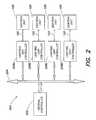
- FIG. 2is a diagram illustrating a networked lighting system according to one embodiment of the disclosure.
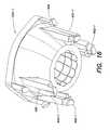
- FIG. 3is a perspective, partial cut away bottom view of a lighting fixture according to one embodiment of the disclosure.
- FIG. 10is a front view of an LED assembly of the light-generating module of FIG. 9 , according to one embodiment of the disclosure.
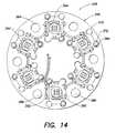
- FIG. 13illustrates LED subassemblies positioned on the jig of FIG. 12 .
- FIG. 15is a perspective view of a secondary optic component according to one embodiment of the disclosure.
- FIG. 16is a perspective view of a secondary optic component according to another embodiment of the disclosure.
- FIG. 17is a perspective view of the secondary optic component of FIG. 16 .
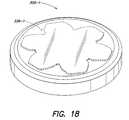
- FIG. 18is a perspective front view of a light-generating module showing ornamental features of the module, according to one embodiment of the disclosure.
- FIG. 19is a perspective rear view of a light-generating module according to one embodiment of the disclosure.
- FIG. 20is a side view of a light-generating module according to one embodiment of the disclosure.
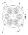
- FIG. 21is a top view of a light-generating module according to one embodiment of the disclosure.
- FIG. 22is a cross-sectional view taken along line 22 - 22 of FIG. 21 .
- FIG. 24is a rear view of the light-generating module of FIG. 21 .
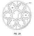
- FIG. 25is a front view of a chassis of the light-generating module of FIG. 9 , according to one embodiment of the disclosure.
- FIG. 26is a rear view of the chassis of FIG. 25 .
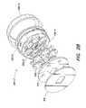
- FIG. 27is an exploded view of a light-generating module according to an alternative embodiment of the disclosure.
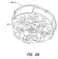
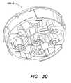
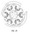
- FIG. 31is a top view of electrical connections present in the chassis of FIGS. 29 and 30 according to one embodiment of the disclosure.
- FIG. 32is a perspective view of a light-generating module including a heat sink according to one embodiment of the disclosure.
- FIG. 34is an exploded view of a light-generating module including a fan according to one embodiment of the disclosure.
- FIG. 35is an exploded view of a light-generating module including a fan according to another embodiment of the disclosure.
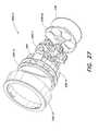
- FIG. 36is a perspective view of a heat sink for a light-generating module.
- FIG. 37is a top view of the heat sink of FIG. 36 .
- FIG. 39is a cross-sectional side view of a recessed joist-mount lighting fixture according to one embodiment of the disclosure.
- FIG. 40is a perspective view of a recessed joist-mount lighting fixture according to one embodiment of the disclosure.
- FIG. 42illustrates a light-generating module being attached to a socket according to one embodiment of the disclosure.
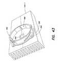
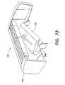
- FIG. 43illustrates a socket attached to a heat sink according to one embodiment of the disclosure
- FIG. 45is a cross-sectional side view of an engagement arrangement according to one embodiment of the disclosure.
- FIG. 46is a perspective view of another embodiment of a light-generating module and a socket
- FIG. 48is a perspective view of a rectangular light-generating module and socket according to one embodiment of the disclosure.
- FIGS. 50 and 51illustrate light-generating modules and sockets according to two alternative embodiments of the disclosure.
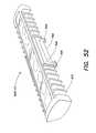
- FIG. 52is a perspective view of a light-generating module according to another embodiment of the disclosure.
- FIG. 53is a perspective view of a light-generating module configured to be upwardly facing.
- FIG. 54is a cross-sectional view of the light-generating module of FIG. 53 and an associated socket.
- FIG. 55is cross-sectional view of a lighting fixture including two upwardly-facing light-generating modules.
- FIGS. 56A-56Eillustrate various embodiments of upwardly-facing light-generating modules.
- FIG. 57is a perspective exploded view of a light-generating module according to one embodiment of the disclosure.
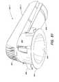
- FIG. 58is a perspective view of a lighting fixture according to one embodiment of the disclosure.
- FIG. 59is a perspective view of a lighting fixture according to one embodiment of the disclosure.
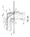
- FIG. 60shows a series of lighting fixture positions as the lighting fixture is installed in an architectural feature.
- FIGS. 61 , 62 and 63are perspective views of the lighting fixture of FIG. 59 .
- FIG. 64is a perspective view of another embodiment of a lighting fixture.
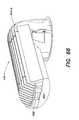
- FIGS. 65 , 66 and 67are perspective views of the lighting fixture of FIG. 64 .
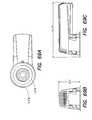
- FIGS. 69A , 69 B and 69 Cshow three orthogonal views of the lighting fixture of FIG. 68 .
- FIG. 70shows a controller module for a lighting fixture according to one embodiment of the disclosure.
- FIGS. 71A , 71 B, 71 Care perspective views of a controller module with various connectors.
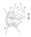
- FIGS. 72 , 73 , 74 , and 75illustrate steps of installing a controller module in a housing according to one embodiment of the disclosure.
- FIG. 1illustrates one example of various components that may constitute a lighting fixture 100 according to one embodiment of the present disclosure.
- LED-based lighting fixturesincluding components similar to those that are described below in connection with FIG. 1 may be found, for example, in U.S. Pat. No. 6,016,038, issued Jan. 18, 2000 to Mueller et al., entitled “Multicolored LED Lighting Method and Apparatus,” and U.S. Pat. No. 6,211,626, issued Apr. 3, 2001 to Lys et al, entitled “Illumination Components,” which patents are both hereby incorporated herein by reference.
- the lighting fixture 100 shown in FIG. 1may include one or more light sources 104 A, 104 B, 104 C, and 104 D (shown collectively as 104 ), wherein one or more of the light sources may be an LED-based light source that includes one or more light emitting diodes (LEDs).
- LEDslight emitting diodes
- any two or more of the light sourcesmay be adapted to generate radiation of different colors (e.g. red, green, blue); in this respect, as discussed above, each of the different color light sources generates a different source spectrum that constitutes a different “channel” of a “multi-channel” lighting fixture.
- the lighting fixtureis not limited in this respect, as different numbers and various types of light sources (all LED-based light sources, LED-based and non-LED-based light sources in combination, etc.) adapted to generate radiation of a variety of different colors, including essentially white light, may be employed in the lighting fixture 100 , as discussed further below.
- the lighting fixture 100also may include a controller 105 that is configured to output one or more control signals to drive the light sources so as to generate various intensities of light from the light sources.
- the controller 105may be configured to output at least one control signal for each light source so as to independently control the intensity of light (e.g., radiant power in lumens) generated by each light source; alternatively, the controller 105 may be configured to output one or more control signals to collectively control a group of two or more light sources identically.
- control signalsthat may be generated by the controller to control the light sources include, but are not limited to, pulse modulated signals, pulse width modulated signals (PWM), pulse amplitude modulated signals (PAM), pulse code modulated signals (PCM) analog control signals (e.g., current control signals, voltage control signals), combinations and/or modulations of the foregoing signals, or other control signals.
- PWMpulse width modulated signals
- PAMpulse amplitude modulated signals
- PCMpulse code modulated signals
- one or more modulation techniquesprovide for variable control using a fixed current level applied to one or more LEDs, so as to mitigate potential undesirable or unpredictable variations in LED output that may arise if a variable LED drive current were employed.
- the controller 105may control other dedicated circuitry (not shown in FIG. 1 ) which in turn controls the light sources so as to vary their respective intensities.
- the intensity (radiant output power) of radiation generated by the one or more light sourcesis proportional to the average power delivered to the light source(s) over a given time period.
- one technique for varying the intensity of radiation generated by the one or more light sourcesinvolves modulating the power delivered to (i.e., the operating power of) the light source(s). For some types of light sources, including LED-based sources, this may be accomplished effectively using a pulse width modulation (PWM) technique.
- PWMpulse width modulation
- the controller 105may be configured to apply the voltage V source to a given light source in a pulsed fashion (e.g., by outputting a control signal that operates one or more switches to apply the voltage to the light source), preferably at a frequency that is greater than that capable of being detected by the human eye (e.g., greater than approximately 100 Hz).
- the controllervaries the average amount of time the light source is energized in any given time period, and hence varies the average operating power of the light source. In this manner, the perceived brightness of the generated light from each channel in turn may be varied.
- the controller 105may be configured to control each different light source channel of a multi-channel lighting fixture at a predetermined average operating power to provide a corresponding radiant output power for the light generated by each channel.
- the controller 105may receive instructions (e.g., “lighting commands”) from a variety of origins, such as a user interface 118 , a signal source 124 , or one or more communication ports 120 , that specify prescribed operating powers for one or more channels and, hence, corresponding radiant output powers for the light generated by the respective channels.
- instructionse.g., “lighting commands”
- the controller 105may receive instructions (e.g., “lighting commands”) from a variety of origins, such as a user interface 118 , a signal source 124 , or one or more communication ports 120 , that specify prescribed operating powers for one or more channels and, hence, corresponding radiant output powers for the light generated by the respective channels.
- the prescribed operating powers for one or more channelse.g., pursuant to different instructions or lighting commands
- one or more of the light sources 104 A, 104 B, 104 C, and 104 D shown in FIG. 1may include a group of multiple LEDs or other types of light sources (e.g., various parallel and/or serial connections of LEDs or other types of light sources) that are controlled together by the controller 105 .
- one or more of the light sourcesmay include one or more LEDs that are adapted to generate radiation having any of a variety of spectra (i.e., wavelengths or wavelength bands), including, but not limited to, various visible colors (including essentially white light), various color temperatures of white light, ultraviolet, or infrared. LEDs having a variety of spectral bandwidths (e.g., narrow band, broader band) may be employed in various implementations of the lighting fixture 100 .
- the lighting fixture 100may be constructed and arranged to produce a wide range of variable color radiation.
- the lighting fixture 100may be particularly arranged such that controllable variable intensity (i.e., variable radiant power) light generated by two or more of the light sources combines to produce a mixed colored light (including essentially white light having a variety of color temperatures).
- controllable variable intensityi.e., variable radiant power
- the color (or color temperature) of the mixed colored lightmay be varied by varying one or more of the respective intensities (output radiant power) of the light sources (e.g., in response to one or more control signals output by the controller 105 ).
- the controller 105may be particularly configured to provide control signals to one or more of the light sources so as to generate a variety of static or time-varying (dynamic) multi-color (or multi-color temperature) lighting effects.
- the controllermay include a processor 102 (e.g., a microprocessor) programmed to provide such control signals to one or more of the light sources.
- the processor 102may be programmed to provide such control signals autonomously, in response to lighting commands, or in response to various user or signal inputs.
- the lighting fixture 100may include a wide variety of colors of LEDs in various combinations, including two or more of red, green, and blue LEDs to produce a color mix, as well as one or more other LEDs to create varying colors and color temperatures of white light.
- red, green and bluecan be mixed with amber, white, UV, orange, IR or other colors of LEDs.
- Such combinations of differently colored LEDs in the lighting fixture 100can facilitate accurate reproduction of a host of desirable spectrums of lighting conditions, examples of which include, but are not limited to, a variety of outside daylight equivalents at different times of the day, various interior lighting conditions, lighting conditions to simulate a complex multicolored background, and the like.
- Other desirable lighting conditionscan be created by removing particular pieces of spectrum that may be specifically absorbed, attenuated or reflected in certain environments.
- the lighting fixture 100also may include a memory 114 to store various information.
- the memory 114may be employed to store one or more lighting commands or programs for execution by the processor 102 (e.g., to generate one or more control signals for the light sources), as well as various types of data useful for generating variable color radiation (e.g., calibration information, discussed further below).
- the memory 114also may store one or more particular identifiers (e.g., a serial number, an address, etc.) that may be used either locally or on a system level to identify the lighting fixture 100 .
- such identifiersmay be pre-programmed by a manufacturer, for example, and may be either alterable or non-alterable thereafter (e.g., via some type of user interface located on the lighting fixture, via one or more data or control signals received by the lighting fixture, etc.). Alternatively, such identifiers may be determined at the time of initial use of the lighting fixture in the field, and again may be alterable or non-alterable thereafter.
- the observed color (or color temperature) of light produced by different lighting fixtures under identical control conditionsmay be perceivably different.
- the “lavender” example abovethe “first lavender” produced by the first lighting fixture with a red command having a value of 125 and a blue command having a value of 200 indeed may be perceivably different than a “second lavender” produced by the second lighting fixture with a red command having a value of 125 and a blue command having a value of 200.
- the first and second lighting fixturesgenerate uncalibrated colors by virtue of their uncalibrated light sources.
- the lighting fixture 100includes calibration means to facilitate the generation of light having a calibrated (e.g., predictable, reproducible) color at any given time.
- the calibration meansis configured to adjust (e.g., scale) the light output of at least some light sources of the lighting fixture so as to compensate for perceptible differences between similar light sources used in different lighting fixtures.
- the processor 102 of the lighting fixture 100is configured to control one or more of the light sources so as to output radiation at a calibrated intensity that substantially corresponds in a predetermined manner to a control signal for the light source(s).
- a calibrated coloris produced.
- at least one calibration value for each light sourceis stored in the memory 114 , and the processor is programmed to apply the respective calibration values to the control signals (commands) for the corresponding light sources so as to generate the calibrated intensities.
- one or more calibration valuesmay be determined once (e.g., during a lighting fixture manufacturing/testing phase) and stored in the memory 114 for use by the processor 102 .
- the processor 102may be configured to derive one or more calibration values dynamically (e.g. from time to time) with the aid of one or more photosensors, for example.
- the photosensor(s)may be one or more external components coupled to the lighting fixture, or alternatively may be integrated as part of the lighting fixture itself.
- a photosensoris one example of a signal source that may be integrated or otherwise associated with the lighting fixture 100 , and monitored by the processor 102 in connection with the operation of the lighting fixture. Other examples of such signal sources are discussed further below, in connection with the signal source 124 shown in FIG. 1 .
- One exemplary method that may be implemented by the processor 102 to derive one or more calibration valuesincludes applying a reference control signal to a light source (e.g., corresponding to maximum output radiant power), and measuring (e.g., via one or more photosensors) an intensity of radiation (e.g., radiant power falling on the photosensor) thus generated by the light source.
- the processormay be programmed to then make a comparison of the measured intensity and at least one reference value (e.g., representing an intensity that nominally would be expected in response to the reference control signal). Based on such a comparison, the processor may determine one or more calibration values (e.g., scaling factors) for the light source.
- one calibration valuemay be derived for an entire range of control signal/output intensities for a given light source.
- multiple calibration valuesmay be derived for a given light source (i.e., a number of calibration value “samples” may be obtained) that are respectively applied over different control signal/output intensity ranges, to approximate a nonlinear calibration function in a piecewise linear manner.
- the controller 105 of the lighting fixturemonitors the user interface 118 and controls one or more of the light sources 104 A, 104 B, 104 C and 104 D based at least in part on a user's operation of the interface.
- the controller 105may be configured to respond to operation of the user interface by originating one or more control signals for controlling one or more of the light sources.
- the processor 102may be configured to respond by selecting one or more pre-programmed control signals stored in memory, modifying control signals generated by executing a lighting program, selecting and executing a new lighting program from memory, or otherwise affecting the radiation generated by one or more of the light sources.
- the user interface 118may constitute one or more switches (e.g., a standard wall switch) that interrupt power to the controller 105 .
- the controller 105is configured to monitor the power as controlled by the user interface, and in turn control one or more of the light sources based at least in part on a duration of a power interruption caused by operation of the user interface.
- the controllermay be particularly configured to respond to a predetermined duration of a power interruption by, for example, selecting one or more pre-programmed control signals stored in memory, modifying control signals generated by executing a lighting program, selecting and executing a new lighting program from memory, or otherwise affecting the radiation generated by one or more of the light sources.
- FIG. 1also illustrates that the lighting fixture 100 may be configured to receive one or more signals 122 from one or more other signal sources 124 .
- the controller 105 of the lighting fixturemay use the signal(s) 122 , either alone or in combination with other control signals (e.g., signals generated by executing a lighting program, one or more outputs from a user interface, etc.), so as to control one or more of the light sources 104 A, 104 B, 104 C and 104 D in a manner similar to that discussed above in connection with the user interface.
- control signalse.g., signals generated by executing a lighting program, one or more outputs from a user interface, etc.
- Examples of the signal(s) 122 that may be received and processed by the controller 105include, but are not limited to, one or more audio signals, video signals, power signals, various types of data signals, signals representing information obtained from a network (e.g., the Internet), signals representing one or more detectable/sensed conditions, signals from lighting fixtures, signals consisting of modulated light, etc.
- the signal source(s) 124may be located remotely from the lighting fixture 100 , or included as a component of the lighting fixture. In one embodiment, a signal from one lighting fixture 100 could be sent over a network to another lighting fixture 100 .
- a signal source 124that may be employed in, or used in connection with, the lighting fixture 100 of FIG. 1 include any of a variety of sensors or transducers that generate one or more signals 122 in response to some stimulus.
- sensorsinclude, but are not limited to, various types of environmental condition sensors, such as thermally sensitive (e.g., temperature, infrared) sensors, humidity sensors, motion sensors, photosensors/light sensors (e.g., photodiodes, sensors that are sensitive to one or more particular spectra of electromagnetic radiation such as spectroradiometers or spectrophotometers, etc.), various types of cameras, sound or vibration sensors or other pressure/force transducers (e.g., microphones, piezoelectric devices), and the like.
- thermally sensitivee.g., temperature, infrared
- humidity sensorse.g., humidity sensors, motion sensors, photosensors/light sensors (e.g., photodiodes, sensors that are sensitive to one or more particular spectra of electromagnetic radiation such as
- a signal source 124includes various metering/detection devices that monitor electrical signals or characteristics (e.g., voltage, current, power, resistance, capacitance, inductance, etc.) or chemical/biological characteristics (e.g., acidity, a presence of one or more particular chemical or biological agents, bacteria, etc.) and provide one or more signals 122 based on measured values of the signals or characteristics.
- electrical signals or characteristicse.g., voltage, current, power, resistance, capacitance, inductance, etc.
- chemical/biological characteristicse.g., acidity, a presence of one or more particular chemical or biological agents, bacteria, etc.
- a signal source 124include various types of scanners, image recognition systems, voice or other sound recognition systems, artificial intelligence and robotics systems, and the like.
- a signal source 124could also be a lighting fixture 100 , another controller or processor, or any one of many available signal generating devices, such as media players, MP3 players, computers, DVD players, CD players, television signal sources, camera signal sources, microphones, speakers, telephones, cellular phones, instant messenger devices, SMS devices, wireless devices, personal organizer devices, and many others.
- signal generating devicessuch as media players, MP3 players, computers, DVD players, CD players, television signal sources, camera signal sources, microphones, speakers, telephones, cellular phones, instant messenger devices, SMS devices, wireless devices, personal organizer devices, and many others.
- the lighting fixture 100 shown in FIG. 1also may include one or more optical elements 130 to optically process the radiation generated by the light sources 104 A, 104 B, 104 C, and 104 D.
- one or more optical elementsmay be configured so as to change one or both of a spatial distribution and a propagation direction of the generated radiation.
- one or more optical elementsmay be configured to change a diffusion angle of the generated radiation.
- one or more optical elements 130may be particularly configured to variably change one or both of a spatial distribution and a propagation direction of the generated radiation (e.g., in response to some electrical and/or mechanical stimulus).
- optical elementsexamples include, but are not limited to, reflective materials, refractive materials, translucent materials, filters, lenses, mirrors, and fiber optics.
- the optical element 130also may include a phosphorescent material, luminescent material, or other material capable of responding to or interacting with the generated radiation.
- the lighting fixture 100may include one or more communication ports 120 to facilitate coupling of the lighting fixture 100 to any of a variety of other devices.
- one or more communication ports 120may facilitate coupling multiple lighting fixtures together as a networked lighting system, in which at least some of the lighting fixtures are addressable (e.g., have particular identifiers or addresses) and are responsive to particular data transported across the network.
- the controller 105 of each lighting fixture coupled to the networkmay be configured to be responsive to particular data (e.g., lighting control commands) that pertain to it (e.g., in some cases, as dictated by the respective identifiers of the networked lighting fixtures).
- particular datae.g., lighting control commands
- the controller 105may read the data and, for example, change the lighting conditions produced by its light sources according to the received data (e.g., by generating appropriate control signals to the light sources).
- the memory 114 of each lighting fixture coupled to the networkmay be loaded, for example, with a table of lighting control signals that correspond with data the processor 102 of the controller receives. Once the processor 102 receives data from the network, the processor may consult the table to select the control signals that correspond to the received data, and control the light sources of the lighting fixture accordingly.
- the processor 102 of a given lighting fixturemay be configured to interpret lighting instructions/data that are received in a DMX protocol (as discussed, for example, in U.S. Pat. Nos. 6,016,038 and 6,211,626), which is a lighting command protocol conventionally employed in the lighting industry for some programmable lighting applications.
- DMX protocolas discussed, for example, in U.S. Pat. Nos. 6,016,038 and 6,211,626
- a lighting command in DMX protocolmay specify each of a red channel command, a green channel command, and a blue channel command as eight-bit data (i.e., a data byte) representing a value from 0 to 255.
- the maximum value of 255 for any one of the color channelsinstructs the processor 102 to control the corresponding light source(s) to operate at maximum available power (i.e., 100%) for the channel, thereby generating the maximum available radiant power for that color (such a command structure for an R-G-B lighting fixture commonly is referred to as 24-bit color control).
- lighting fixtures suitable for purposes of the present disclosureare not limited to a DMX command format, as lighting fixtures according to various embodiments may be configured to be responsive to other types of communication protocols/lighting command formats so as to control their respective light sources.
- the processor 102may be configured to respond to lighting commands in a variety of formats that express prescribed operating powers for each different channel of a multi-channel lighting fixture according to some scale representing zero to maximum available operating power for each channel.
- the lighting fixture 100 of FIG. 1may include and/or be coupled to one or more power sources 108 .
- power source(s) 108include, but are not limited to, AC power sources, DC power sources, batteries, solar-based power sources, thermoelectric or mechanical-based power sources and the like.
- the power source(s) 108may include or be associated with one or more power conversion devices that convert power received by an external power source to a form suitable for operation of the lighting fixture 100 .
- one or more optical elements as discussed abovemay be partially or fully integrated with an enclosure/housing arrangement for the lighting fixture.
- the various components of the lighting fixture discussed abovee.g., processor, memory, power, user interface, etc.
- other components that may be associated with the lighting fixture in different implementationse.g., sensors/transducers, other components to facilitate communication to and from the unit, etc.
- any subset or all of the various lighting fixture components, as well as other components that may be associated with the lighting fixturemay be packaged together.
- packaged subsets of componentsmay be coupled together electrically and/or mechanically in a variety of manners, as discussed below.
- FIG. 2illustrates an example of a networked lighting system 200 according to one embodiment of the present disclosure.
- a number of lighting fixtures or fixtures 100similar to those discussed above in connection with FIG. 1 , are coupled together to form the networked lighting system. It should be appreciated, however, that the particular configuration and arrangement of lighting fixtures shown in FIG. 2 is for purposes of illustration only, and that the disclosure is not limited to the particular system topology shown in FIG. 2 .
- the networked lighting system 200may be configured flexibly to include one or more user interfaces, as well as one or more signal sources such as sensors/transducers.
- one or more user interfaces and/or one or more signal sourcessuch as sensors/transducers (as discussed above in connection with FIG. 1 ) may be associated with any one or more of the lighting fixtures of the networked lighting system 200 .
- one or more user interfaces and/or one or more signal sourcesmay be implemented as “stand alone” components in the networked lighting system 200 .
- these devicesmay be “shared” by the lighting fixtures of the networked lighting system.
- one or more user interfaces and/or one or more signal sourcessuch as sensors/transducers may constitute “shared resources” in the networked lighting system that may be used in connection with controlling any one or more of the lighting fixtures of the system.
- the central controller 202 shown in FIG. 2may by configured to implement Ethernet-based communications with the LUCs, and in turn the LUCs may be configured to implement DMX-based communications with the lighting fixtures 100 .
- each LUCmay be configured as an addressable Ethernet-based controller and accordingly may be identifiable to the central controller 202 via a particular unique address (or a unique group of addresses) using an Ethernet-based protocol.
- the central controller 202may be configured to support Ethernet communications throughout the network of coupled LUCs, and each LUC may respond to those communications intended for it.
- each LUCmay communicate lighting control information to one or more lighting fixtures coupled to it, for example, via a DMX protocol, based on the Ethernet communications with the central controller 202 .
- the operatormay provide a simple instruction to the central controller 202 to accomplish this, and in turn the central controller may communicate to one or more LUCs using an Ethernet-based protocol high level command to generate a “rainbow chase.”
- the commandmay contain timing, intensity, hue, saturation or other relevant information, for example.
- a given LUCmay then interpret the command and communicate further commands to one or more lighting fixtures using a DMX protocol, in response to which the respective sources of the lighting fixtures are controlled via any of a variety of signaling techniques (e.g., PWM).
- one or more lighting fixtures as discussed aboveare capable of generating highly controllable variable color light over a wide range of colors, as well as variable color temperature white light over a wide range of color temperatures.
- FIG. 3illustrates a perspective, partial cutaway view of a lighting fixture 100 having modular construction according to one embodiment of the disclosure.
- a light-generating module 300such as an LED-based module, is attachable to and detachable from a mating socket 302 .
- the socket 302is fixedly coupled to a housing 304 (e.g., via screws inserted through holes 306 in flanges 308 of the socket 302 ), and the light-generating module 300 may be easily installed in the housing 304 , via the socket 302 , to form the lighting fixture 100 .
- the housing 304may serve as a heat sink (e.g., the housing may be formed from a significantly thermally conductive material, such as die-cast or extruded metal).
- the lighting fixture 100 of this embodimentfurther includes a controller module 105 as a separate component from the light-generating module 300 that may be permanently or replaceably mounted within the housing 304 .
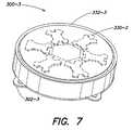
- the overall shape of the light-generating module 300may resemble a hockey puck.
- a circular light-generating modulemay have a diameter of approximately three inches and a thickness of approximately one inch.
- the thickness of the light-generating module near the center of the light-generating moduleis greater than the thickness near the edges.
- FIG. 4shows a perspective view of a fully assembled modular lighting fixture 100 similar to that shown in FIG. 3 , including a reflector cone 314 and mounting brackets 316 .
- the reflector cone 314may be removable to facilitate replacement of the light-generating module 300 and/or the controller module 105 .
- FIG. 5shows a top perspective view of the fully assembled lighting fixture 100 .
- the lighting fixture 100includes thermal dissipation elements 320 (fins in this embodiment) for transferring heat away from the light-generating module 300 and/or the controller module 105 .
- the socket 302may be formed with a thermally conductive material to facilitate transfer of heat from the light-generating module 300 to the housing 304 , which in turn transfers heat to the fins or other suitable thermal dissipation elements.
- Wiring knockouts 322 and a wiring compartment door 324are also visible in this view.
- thermal dissipation elementsi.e., thermally isolated from thermal dissipation elements that transfer heat away from the light-generating module
- thermal dissipation elementstransfer heat away from both the light-generating module 300 and the controller module 105 .
- FIG. 6illustrates a perspective view of another embodiment of a modular lighting fixture 100 - 1 which includes a housing 304 - 1 having a shape that differs from the embodiment illustrated in FIGS. 3-5 .
- the embodiment illustrated in FIG. 6may be useful for installation and/or removal through holes in ceilings or walls, as discussed in more detail further below.
- the lighting fixture 100 - 1includes a light-generating module 300 , a socket 302 and a reflector cone 314 .
- the controller module 105 associated with a given lighting fixturemay be disposed internally within the housing, as illustrated in FIG. 3 , while in other embodiments, the controller module 105 may be disposed externally (e.g., in a junction box such as the junction box shown in FIG. 68 ).
- FIGS. 7 and 8illustrate perspective views of an assembled light-generating module 300 - 3 attached to a socket 302 - 3 of a lighting fixture according to one embodiment of the disclosure.
- the exemplary embodiment depicted in FIGS. 7 and 8is discussed in further detail below in connection with FIGS. 27-31 .
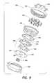
- FIG. 9illustrates an exploded perspective view of a light-generating module 300 , a socket 302 and a grip ring 332 , according to yet another embodiment of the present disclosure.
- the illustrations of FIGS. 7-9represent two exemplary embodiments of a light-generating module, and each component described with reference to FIGS. 7-9 is not necessarily required to form a light-generating module according to other embodiments.
- the components of the light-generating module 300include a light-passing (e.g., transparent or translucent) face plate 330 , the grip ring 332 , secondary optic components 334 , a chassis 336 , an LED assembly 338 , and an aluminum base plate 340 .
- the chassis 336is configured as a metal die-cast component to facilitate heat transfer (in other embodiments, as discussed below in connection with FIGS. 27-31 , a similar chassis may be formed as an injected molded component made of plastic.)
- the chassis 336is configured to support a number of the secondary optic components 334 .
- the LED assembly 338includes multiple hexagonally-shaped LED subassemblies 344 (hereafter “LED hex subassemblies”) which are sandwiched between a thermally conductive base plate (aluminum base plate 340 ) and a printed circuit board substrate 346 .
- the combination of the base plate 340 , hex subassemblies 344 and printed circuit board 346may in turn be covered with an electrically insulating and thermally conducting layer 348 and coupled to the chassis 336 (e.g., via screws which pass through holes in the base plate and engage with threaded bores in the chassis 336 ).
- an electrically insulating and thermally conducting layer 348may be employed between the LED assembly 338 and the chassis 336 , as illustrated in FIG. 9 .
- thermal transfermay occur via the front of the LED assembly (via the printed circuit board 346 , the thermally conducting layer 348 , and the die-cast metal chassis 336 ), as well as via the rear of the LED assembly 338 (via optional thermal paste or grease, the base plate 340 , and ultimately to a housing or other heat sink to which the base plate may in turn be coupled, e.g., see FIG. 3 ).
- Components other than the chassismay be made from thermally conductive material, and various of the die-cast components may be painted/anodized black to facilitate heat transfer.
- FIGS. 7-9illustrates a module that accommodates six LED hex subassemblies 344
- the disclosureis not limited in this respect, as different configurations and numbers of LED subassemblies 344 may be employed in other embodiments.
- an LED subassembly having a shape other than a hexagonal shapemay be substituted for an LED hex subassembly.
- FIG. 10is a close-up front view of the LED assembly 338 of the light-generating module 300 illustrated in FIG. 9 .
- FIG. 10illustrates six LED hex subassemblies 344 (e.g., OSTAR® subassemblies, which are described in more detail below) coupled to a printed circuit board 346 .
- each hex subassembly 344includes six individual LED junctions 358 that are electrically interconnected in the subassembly so as to be operated simultaneously in response to a drive signal applied to the subassembly.
- Each subassemblyalso includes a primary optic 360 which may be a lens configured to provide a Lambertian beam shape.
- the hex subassemblies 344are coupled to a rear or bottom surface of the printed circuit board 346 , and the printed circuit board is configured with through holes for the primary optic 360 of each hex subassembly 344 .
- Large through-holes 364 in the printed circuit board 346facilitate attachment of the base plate 340 and the LED assembly 338 to the chassis 336 .
- the LED hex subassemblies 344may be components manufactured under the name OSTAR® by OSRAM Opto Semiconductors Gmbh (see http://www.osram-os.com/ostar-lighting). Each OSTAR® subassembly 344 may provide up to 400 lumens of radiation at an operating current of 700 milliamps from six LED junctions that are driven simultaneously to provide white light having a color temperature of approximately 5600 degrees Kelvin.
- LED hex subassemblies 344may be implemented as “chip-on-board” LED subassemblies or modules.
- a chip-on-board assemblyan unpackaged silicon die (i.e., semiconductor chip) is attached directly onto the surface of a substrate (e.g., an FR-4 printed circuit board, a flexible printed circuit board, a ceramic substrate, etc.) and wire bonded to form electrical connections to the substrate.
- a substratee.g., an FR-4 printed circuit board, a flexible printed circuit board, a ceramic substrate, etc.
- An epoxy resin or a silicone coatingis then applied on top of the die/chip to encapsulate and protect the die/chip.
- the LED hex subassemblyincludes four or six LED semiconductor chips mounted on a ceramic substrate, which is in turn mounted directly to a surface of a metal core printed circuit board.
- the chipsmay be coated with a clear silicone encapsulant.
- Each OSTAR®includes an aluminum core substrate to facilitate thermal dissipation, on top of which is disposed electrical connections, the LED junctions (semiconductor chips), and an integrated primary lens (as one example of a primary optic) to provide a Lambertian beam shape.
- the hexagonally-shaped substrateis provided with multiple perimeter cut-outs and/or through-holes to permit coupling of the subassemblies via screws to the chassis 336 and also to facilitate registration of the individual hex subassemblies to a common substrate, as well as optional secondary optics. Electrical connections to the hex subassemblies may be made by soldering to contacts on the top of the subassembly, or by employing spring type contacts.
- LED hex subassemblyconstituted by an OSTAR® component
- OSTAR® componentan example of an LED hex subassembly constituted by an OSTAR® component
- the disclosureis not limited in this respect, as LED hex subassemblies having other configurations, including one or more LEDs configured to generate essentially white light having a variety of color temperatures and/or light having a variety of non-white colors, may be employed in light-generating modules according to various embodiments.
- FIG. 11is a close-up rear view of the LED assembly 338 , showing the rear mounting of the hex subassemblies 344 to the printed circuit board 346 , as well as the electrical connector 352 that provides one or more drive signals for operating the hex subassemblies. From FIG. 11 , a rear surface 368 of the aluminum substrate of each hex subassembly 344 is clearly visible. With reference again to FIG. 9 , in one aspect of this embodiment, the rear surfaces of the hex subassemblies are coupled to the aluminum base plate 340 to facilitate thermal transfer from the back (or bottom surface) of the hex subassemblies.
- thermal grease or pastemay be used to adhere the base plate 340 to the LED assembly 338 , such that through-holes 370 in the base plate 340 are aligned with the large through-holes 364 in the printed circuit board 346 to facilitate attachment of the base plate and the LED assembly to the chassis 336 .
- the base plate 340may include a center cut-out or through-hole to allow for clearance of the electrical connector 352 .
- FIG. 12illustrates a “jig” 380 that may be employed to facilitate assembly of the LED assembly 338 .
- the jig 380may be constructed of any rigid material, such as an aluminum plate.
- the aluminum platemay include a number of holes into which are placed small pegs 384 and large pegs 386 .
- the different sized pegsensure proper registration between the hex subassemblies 344 and the printed circuit board 346 .
- a side of the printed circuit board 346 adjacent to the hex subassembliesincludes first electrical contacts (e.g., copper pads—not shown), in complementary positions to the contact pads 388 on the hex subassemblies 344 , which provide both mechanical attachment points and electrical connections to the hex subassemblies.
- these first electrical contactshave counterpart second electrical contacts 390 that appear on the opposite side of the printed circuit board 346 (the side in the view of FIG. 14 ) and the contact pairs on opposing sides of the printed circuit board may be connected via plated through-holes 392 in the middle of the contacts.
- heatmay be applied to the second electrical contacts 390 (e.g., via a hot bar or soldering iron tip), thereby causing the solder paste to melt and form electrical and mechanical bonds between the hex subassemblies and the printed circuit board.
- the plated through-holes 392facilitate heat transfer through the contacts and also allow visual inspection of the solder bond.
- the printed circuit board 346may be made of conventional FR-4 (Flame Resistant 4) material, which is commonly used for making printed circuit boards and is a composite of a resin epoxy reinforced with a woven fiberglass mat.
- FR-4Flume Resistant 4
- a printed circuit board 346 made of FR-4may be fabricated as a relatively thin substrate to facilitate effective thermal transfer from the front (or top surface) of the hex subassemblies.
- the metal of the chassisfurther facilitates thermal transfer from the front (or light-exit face) of the light-generating module.
- the printed circuit boardmay be made of a flexible circuit board material.
- Flexible circuit boardsare used in some common conventional applications where flexibility, space savings, or production constraints limit the serviceability of rigid circuit boards or hand wiring.
- a common application of flexible circuitsis in computer keyboard manufacturing; most keyboards made today use flexible circuits for the switch matrix.
- a flexible circuit boardmay be implemented as an appreciably thin substrate (e.g., on the order of a few micrometers) using thin flexible plastic or other insulating material and metal foil for conductors.
- a suitable flexible insulating material for flexible circuit boardsis Kapton®, which is a polyimide film developed by DuPont® that can remain stable in a wide range of temperatures, from ⁇ 269° C. to +400° C. ( ⁇ 452° F. to 752° F.).
- windowsmay be cut into the insulating material on both the top and the bottom of the circuit board to expose contact pad areas in the conducting metal foil layer. Holes may be formed in the middle of these areas to facilitate the soldering process, as discussed above.
- a non-planar LED assemblymay be fabricated and appropriately mounted to a chassis to allow customized or predetermined patterns and directions of light emission from the LEDs of the hex subassemblies.
- an aluminum base plate serving as an alternative to the base plate 340may be equipped with pegs similar to those illustrated in FIG. 12 , such that the LED hex subassemblies first are mounted in appropriate positions on the rigid base plate.
- the pegs in the base platethen would also serve to facilitate registration of the flexible circuit board, which may be placed on top of the hex subassemblies and bonded to the subassemblies in a manner similar to that described above.
- FIG. 15shows a close-up view of the secondary optic component 334 of the light-generating module 300 shown in FIG. 9 .
- Each secondary optic componentis configured with four posts 402 which engage with four corresponding small through-holes 372 of the printed circuit board to facilitate registration of the secondary optic over the primary optic of an associated LED hex subassembly 344 .
- Each secondary optic 334also may include one or more clips 404 to facilitate engagement of the secondary optic with one of the secondary optic receiving portions of the chassis 336 . More specifically, with reference to FIGS. 9 , 25 and 26 , each secondary optic fits into a corresponding secondary optic receiving portion or chamber 502 of the chassis 336 , and the one or more clips 404 engage with a portion of a bottom surface 504 of the chassis 336 .
- the posts 402 of the secondary opticpass through the secondary optic receiving portion or chamber of the chassis, and engage with the small through-holes 372 and the perimeter semi-circle cut outs 374 of an associated LED hex subassembly (e.g., see FIGS. 10 and 11 ) to ensure that the secondary optic is appropriately aligned with the primary optic of its associated LED hex subassembly.
- the secondary opticmay be configured with baffled, curved, and/or reflective surfaces to facilitate generation of a variety of beam profiles (e.g., narrow beam, medium beam) for the light radiated by the LED hex subassemblies.
- FIGS. 16 and 17A slightly different embodiment of a secondary optic component 334 - 1 is illustrated in FIGS. 16 and 17 .
- four posts 402 - 1include a flat outwardly-facing surface 406 rather than a curved outwardly surface as shown in the embodiment of FIG. 15 .
- FIGS. 18 and 19are perspective views showing the ornamental design of one embodiment of a round puck-shaped light-generating module 300 - 1 including a chassis 336 - 1 , a base plate 340 - 1 and a connector 352 - 1 .
- FIG. 20is a side view of the light-generating module 300 - 1 of FIGS. 18 and 19 .
- FIG. 21is a top view showing the ornamental design of another embodiment of a round light-generating module 300 - 2 coupled to a socket 302 - 2 via a grip ring 332 - 2 , wherein the flanges 308 - 2 of the socket are visible
- FIG. 22shows a cross-sectional view of the light-generating module and grip ring taken along line 22 - 22 of FIG.
- FIG. 23is a top perspective view of the light-generating module 300 - 2 , grip ring 332 - 2 , and socket 302 - 2 of FIG. 21 .
- FIG. 24is a bottom view of the light-generating module 300 - 2 and grip ring 332 - 2 of FIG. 21 .
- the socket and grip ringessentially form two mating collars, wherein at least one exterior feature of the socket and at least one interior feature of the grip ring include complementary threads to facilitate a screw-type interlocking mechanical connection as the grip ring is placed on and rotated relative to the socket. Accordingly, when the light-generating module is installed in the socket, the grip ring is configured to fit over at least a portion of a perimeter of the light-generating module and hold the light-generating module in the socket via the screw-type (rotating) interlocking mechanical connection.
- FIG. 25is a top view of the ornamental design of one embodiment of a chassis 336 - 1 including multiple chambers 502 .
- FIG. 26is a bottom perspective view of the chassis 336 - 1 of FIG. 25 , illustrating multiple threaded bores 504 formed in the body of the chassis for receiving screws that may be used to coupled the base plate and the LED assembly to the chassis.
- FIGS. 27 and 28illustrate two different exploded perspective views of a light-generating module 300 - 3 and grip ring 332 - 3 according to an alternative embodiment of the disclosure.
- an LED assembly 338 - 1 including a number of LED hex subassemblies 344 - 1is not arranged to be sandwiched between a thermally conductive base plate and a printed circuit board substrate, but instead is configured to be inserted into a chassis 336 - 2 .
- FIGS. 29 and 30illustrate various views of the chassis 336 - 2 including six complementary receiving portions or chambers to accommodate six LED hex subassemblies 344 - 1 .
- the chassis 336 - 2may be an injected molded component made of plastic.
- the chassis 336 - 2may be configured to include a number of electrical connectors 410 and contacts 412 integral with the body of the chassis 336 - 2 so as to provide operating power to each of the LED hex subassemblies 344 - 1 from a main connector assembly 352 - 2 disposed in a center channel of the chassis 336 - 2 .
- One particular layout of the electrical contacts 412 and connectors 410is shown in a top view in FIG. 31 .
- the electrical contacts or connectors of the chassis 336 - 2may include: components which are insert-molded into the chassis; stamped pieces which may be pressed into the chassis during assembly; a flex printed circuit board (flex PCB); or conductive ink screened onto the molded chassis.
- the LED hex subassemblies 344 - 1may be assembled into the chassis 336 - 2 by pressing to ensure satisfactory electrical contact with the contacts or connectors of the chassis.
- the chassismay further include small fasteners or retention clips in the injection molded plastic.
- thermal materialssuch as viscous paste or liquid metal sandwiched between the plate and a thin and slightly convex sheet.
- this convex sheetdeforms under compression to flatness against the fixture housing (e.g., a heat sink—described below with reference to FIG. 43 ).
- a thin sheet of very soft metalsuch as indium (Brinell hardness 0.9), that can deform under pressure, can replace the gap pad.
- the gap pad or other thermal materialmay be manufactured with wings or flaps that fold up through or around the base plate and were pinched/captured when the base plate is fastened to the chassis.
- various components and/or subassemblies of the light-generating module 300may be configured to conduct heat away from the light-generating module 300 .
- the chassis 336may be die-cast in metal, or formed with another suitable thermally conducting material, such that heat may be transmitted from the LED assembly 338 to the face plate 330 and/or the grip ring 332 .
- the electrically insulating and thermally conducting layer 348 discussed abovemay be interposed between the LED assembly 338 and the chassis 336 as part of facilitating thermal dissipation. In this manner, thermal dissipation may be facilitated from the front face and/or the sides of the light-generating module 300 .
- Thermal dissipationalso may be facilitated from the rear side of the light-generating module 300 in some embodiments.
- a thermally conductive base plate 340may be provided as a backing to the LED assembly 338 such that thermal dissipation is facilitated through the housing and/or socket to which the light-generating module 300 is attached.
- a light-generating modulemay include one or more active thermal dissipation components such as a fan, and/or may include passive thermal dissipation features such as fins or air circulation paths or channels.
- active thermal dissipation componentssuch as a fan
- passive thermal dissipation featuressuch as fins or air circulation paths or channels.
- Such embodimentsmay be useful with certain LED assemblies and light-generating modules in that the use of thermal dissipation components may allow the light-generating module to be a stand-alone unit in terms of thermal dissipation. That is, thermal coupling to a housing or other fixture may not be required for suitable thermal dissipation. In this manner, flexibility may be achieved in terms of associating the light-generating module with various lighting fixtures and systems.
- FIGS. 32 and 33One embodiment of a light-generating module 300 - 4 employing thermal dissipation fins 510 is illustrated in FIGS. 32 and 33 .
- the fins 510are integral to the light-generating module 300 - 4 in that the fins 510 are included as part of a die-cast metal light-generating module housing 512 .
- An LED assembly 514is thermally coupled to the die-cast housing 512 such that heat may be transferred to the thermal dissipation fins 510 .
- the module housing 512includes an insert molded copper core 516 and an injection molded flange 518 for mating engagement with a socket 302 - 2 , as shown in FIG. 33 .
- the socket 302 - 2 in this embodimentis die-cast metal, the plastic flange 518 prevents any appreciable amount of heat from transferring to the socket 302 - 2 in this embodiment.
- the socket 302 - 2may be thermally conductive to facilitate heat transfer.
- the module housing 512includes leaf springs 520 for forming operating power and control connections with the socket 302 - 2 when the light-generating module 300 - 4 is engaged with the socket 302 - 2 .
- FIG. 34One embodiment of a light-generating module 300 - 5 including a fan 530 is illustrated in FIG. 34 .
- the fan 530is disposed between an LED assembly 338 - 2 and a module housing 512 - 1 .
- the fan 530which may be a low RPM fan, draws air into the housing 512 - 1 through intake vents 532 , and expels air from the module 300 - 5 through exhaust vents 534 .
- heatis transferred from LED subassemblies 344 - 2 to thermal dissipation fins 510 - 1 through a metal core printed circuit board 346 - 1 .
- the airflow created by the fan 530passes over the thermal dissipation fins 510 - 1 and removes heat from the thermal dissipation fins 510 - 1 before exiting the module housing 512 - 1 through the exhaust vents 534 .
- Any airflow which directly passes over the metal core printed circuit board 346 - 1 and/or the LED subassemblies 344 - 2also may remove heat.
- the particular arrangement or configuration of the thermal dissipation fins 510 - 1may differ from those illustrated in this embodiment.
- More than one fanmay be used for a given light-generating module 300 - 5 .
- operation of the fan 530may be controlled using temperature sensing or measurements of the amount of energy supplied to the LED assembly 338 - 2 .
- FIG. 35Another embodiment of a light-generating module 300 - 6 including a fan 530 - 1 is illustrated in FIG. 35 .
- the fan 530 - 1such as a low decibel fan
- An LED assembly 338 - 3(the backside of which is visible in FIG. 35 ) is thermally coupled to the heat sink 540 (e.g., with a gap pad, viscous paste or liquid metal).
- the heat sink 540has fins 510 - 2 which form channels 542 through which air flows.
- the LED assembly 338 - 3 and a chassis 336 - 3 for supporting secondary optic components 334 - 2may be removably attached to the heat sink 540 , for example with screws.
- the LED assembly 338 - 3 and the chassis 336 - 3may be permanently attached to the heat sink 540 and the entire light-generating module 300 - 6 incorporating all of the components illustrated in FIG. 35 may be attachable to and removable from lighting fixture housings by a user.
- the heat sink 540also may serve as a housing or a support for additional components, electronic or otherwise, for the light-generating module 300 - 6 .
- the thermal componentsinclude a thermally conductive base plate 340 - 3 , fins 510 - 3 , and a cover 550 .
- the componentsmay be configured to facilitate a flow of air past certain of the thermal dissipation components (such as the fins 510 - 3 ), as shown in FIGS. 37 and 38 .
- one or more fans 530 - 2may be employed to promote an air flow through channels 542 - 1 formed by the fins 510 - 3 .
- the cover 550may be configured to allow the light-generating module 300 - 7 to be attached with screws to a housing 304 - 2 of a lighting fixture 100 - 2 , or, in some embodiments, the cover may be configured to allow the light-generating module 300 - 7 to be clipped or snapped into place within the fixture housing 304 - 2 .
- the cover 550may include contacts 352 - 3 for operating power and/or control connectivity, or the cover 550 may include a hole for allowing access to power and/or control contacts on an LED subassembly.
- a mounting bracket 316may be designed to mount, for example, between joists, beams or similar architectural features of a ceiling 560 , so that the lighting fixture 100 - 2 is recessed, with the lower portion of the lighting fixture 100 - 2 being disposed substantially flush with the ceiling 560 .
- the lighting fixture 100 - 2may be configured to hold a removable light-generating module (e.g., the light-generating module 300 - 7 ).
- the lighting fixture 100 - 2may include a controller, as well as other components, which may be disposed in a controller housing 562 .
- a wiring compartment 564may include various electronic components, such as wires for supplying operating power and data to the light-generating module 100 - 2 .
- the controller housing 562 and/or the wiring compartment 564may be configured to provide the recessed lighting fixture 100 - 2 with a low vertical profile, so as to minimize the height of the recessed lighting fixture 100 - 2 within the ceiling 560 .
- the profile of the recessed lighting fixture 100 - 2may have an approximately four inch depth above the ceiling 560 , such as to connect to a two-by-four stud or joist without requiring additional space above the ceiling.
- the light-generating module 300 - 5 described with reference to FIG. 34may be used within a recessed joist-mount lighting fixture 100 - 2 according to yet another embodiment of the disclosure.
- the recessed lighting fixture 100 - 2may include a housing 304 - 2 and mounting brackets 316 configured for mounting the lighting fixture 100 - 2 in a ceiling 560 or other suitable location.
- the light-generating module 300 - 5is shown being removed from the recessed lighting fixture 100 - 2 in FIG. 41 .
- the light-generating module 300may include no control facilities within the module, or may include a very limited amount of memory, processing or control facilities within the light-generating module 300 .
- the light-generating module 300may receive drive signals for LEDs from an external controller module (that is, a controller not disposed on the light-generating module 300 ) and provide no further control of the LEDs and provide no feedback or information to the external controller module.
- the light-generating module 300may include various memory, processing or control facilities on the light-generating module 300 itself.
- the light-generating module 300may include a unique identification code such a serial number.
- the serial numbermay be available for reading by an external controller module, and information associated with the serial number may be present within memory associated with the controller module, and/or information associated with the serial number may provided to the controller module from an external source.
- the controller modulereads the unique identification code of the light-generating module 300 and accesses a database that contains information specific to the light-generating module 300 .
- an identification codemay identify a group of light-generating modules 300 having similar or identical characteristics, and not identify a specific light-generating module 300 .
- the light-generating module 300may include only an identification code, from which further information can be accessed, as discussed above. Alternatively, in some embodiments, the light-generating module 300 may include additional information within memory on the light-generating module 300 . Examples of information which may be included on the light-generating module 300 include, but are not limited to: operating power requirements; operating power output rating; descriptions of LED sources; light generating characteristics or parameters relating to color or color temperature; description of optical beam angles; calibration parameters; operating temperature; instructions for controller action related to operating temperature; and historical data relating to temperature, time or other light generating characteristics.
- the operating power requirementsmay be provided by the light-generating module 300 in terms of voltage or current, and may include any other suitable information regarding the supply of power to the light-generating module 300 .
- the operating power output ratingmay provide an output rating in terms of watts or lumens, and may include information regarding any predicted degradation over time.
- a description of LED-based sourcesmay include the type and/or number of RGB LEDs and/or white LEDs, and color temperature specifications.
- Information regarding the optical beam angles and/or feasible optical beam anglesmay be included in some embodiments.
- Information regarding a predicted usable life spanmay be included in some embodiments.
- the light-generating module 300may communicate operating temperature measurements to the controller, and, in some embodiments, may provide data or instructions to the controller regarding desired power levels based on operating temperature measurements.
- the light-generating module 300may instruct the controller to reduce the power being supplied to the light-generating module 300 when a certain threshold operating temperature is reached.
- historical datasuch as the number of hours of run-time, the historical operating temperatures, or other data, may be supplied by the light-generating module 300 to the controller or other suitable device.
- the information and/or instructions provided by the light-generating module 300may be initiated by the light-generating module 300 itself and communicated to the controller.
- the controller, or other reading devicemay prompt the light-generating module 300 for information, or read information directly from a memory module or other suitable component of the light-generating module 300 .
- a socket 302may be employed to replaceably attach a light-generating module to a housing or heat sink of a lighting fixture.
- a grip ring 332is rotatable on a molded ridge feature 580 of the chassis 336 and includes embossed features (e.g., posts 582 ) that follow and engage with a complementary spiral path 584 on the socket 302 to lock the module to the socket.
- the socket 302also may include a key 586 to provide a straight docking path for the engagement of the light- generating module to the socket 302 . The key 586 prevents the light-generating module (other than the grip ring 332 ) from rotating within the socket 302 .
- rotation of the grip ring 332does not substantially affect the orientation of the LED assemblies. Additionally, the orientation of any connectors on the back side of the light-generating module does not change, thereby allowing orientation-specific connectors to be mated with complementary connectors on the housing.
- the light-generating modulemay be easily attached to a lighting fixture, and thermal, mechanical and electrical connections may automatically occur as a result of the attachment.
- one or more additional stepsmay be required of the user to form all connections of the light-generating module to the housing.
- the physical and thermal coupling of the light-generating module to the housingmay occur by twisting the light-generating module into the socket as described with reference to FIG. 42 , and the electrical connection of the light-generating module to the housing may be subsequently achieved by separately plugging a connector of the light-generating module into a connector of the housing.
- an electrical contact or other meansmay be incorporated with the socket 302 to detect when the grip ring 332 has reached a locked position, so that drive signals and/or operating power to the LED hex subassemblies are not applied unless the light-generating module 300 is completely locked into the socket 302 .
- FIG. 43illustrates one embodiment of the socket 302 mounted to a heat sink 540 - 1 , which may form a thermally conductive portion of a fixture housing.
- the socket 302may be bolted or otherwise fastened to the heat sink 540 - 1 using through-holes 306 in flanges 308 .
- a through-hole 590may be provided in the heat sink 540 - 1 for an electrical connector.
- other manners of securing the socket 302 to a heat sink, housing, or lighting fixturemay be employed, and in some embodiments, the socket 302 may be integrally connected to the housing.
- An attachment element other than a socketmay be used in some embodiments to attach the light-generating module to the housing.
- the light-generating modulemay be attached to the housing using an adhesive.
- fastenerssuch as screws or bolts may be used to attach the light-generating module, and in this manner, no socket may be present.
- FIGS. 44A and 44Billustrate an alternative embodiment of a socket 302 - 3 in which a stamped sheet 602 includes locking grooves 604 for receiving posts 606 of a light-generating module 300 - 8 .
- the posts 606are inserted into the locking grooves 604 and turned clockwise.
- a detentmay be used to releasably lock the light-generating module 300 - 8 to the socket 302 - 3 .
- a rounded end 610 of one or more of the posts 606may engage with a raised portion 612 of the stamped sheet to provide stability in the attachment (see FIG. 45 ).
- a bent portion 614 of the stamped sheetmay be biased to press on the post 606 to further secure the attachment.
- a keyed center post 620may be used to correctly orient contact pads 616 of the light-generating module 300 - 8 with leaf spring contacts 618 present on the stamped sheet 602 .
- the contact pads 616instead may be present on the stamped sheet 602 and the leaf spring contacts 618 may be present on the light-generating module 300 - 8 .
- Other suitable connection assembliesmay be used to achieve electrical and/or mechanical connections.
- FIGS. 46 and 47show another alternative embodiment of a socket 302 - 4 and light-generating module 300 - 9 .
- the light-generating module 300 - 9includes at least two flexible wings 628 which can deform inwardly, thereby allowing engagement elements 630 to move inwardly when pressing the light-generating module into the socket. Once the engagement elements reach a groove 632 in the socket 302 - 4 , the flexible wings 628 move outwardly and the engagement elements engage with the groove 632 and hold the light-generating module 300 - 9 in the socket 302 - 4 .
- a spring-biased contact plate 636is disposed at a base of the socket 302 - 4 to facilitate electrical connection to the light-generating module. To remove the light-generating module 300 - 9 from the socket 302 - 4 , a user pushes one or more of the flexible wings 628 inwardly to release the engagement elements 630 from the groove 632 .
- the socket 302 - 5is substantially rectangular.
- the light-generating module 300 - 10includes one or more tabs 640 which engage with corresponding compliant catches 642 in a heat sink 540 - 2 .
- the light-generating module 300 - 10may include a thermally conductive gap pad 644 to facilitate thermal conductance to the heat sink 540 - 2 .
- the heat sink 540 - 2may be part of a lighting fixture 100 - 3 which includes a hinged mounting bracket 646 .
- FIG. 49Another embodiment of a substantially rectangular socket is illustrated in FIG. 49 .
- a lighting fixture 100 - 4which hangs from a ceiling is configured to hold light-generating modules that project light upwardly.
- One or more hangars 650support the lighting fixture 100 - 4 and also may provide a conduit for wires that carry operating power and/or control signals to a controller 105 .
- One or more sockets 302 - 6face upwardly and include an electrical connector 310 for engagement with an electrical connector on a light-generating module.
- a light-generating modulemay be secured to the lighting fixture 100 - 4 by passing a screw through the light-generating module and into a threaded hole 652 present on a base of the socket 302 - 6 .
- a light-generating module 300 - 11which also is substantially rectangular includes LED assemblies 338 and “clicks” into place (snap-fits) in the socket 302 - 7 .
- the light-generating module 300 - 11includes spring-biased catches 660 which protrude into grooves 662 in the socket 302 - 7 to hold the light-generating module 300 - 11 in place. In some embodiments, the catches may be locked in the deployed or undeployed positions with a tool.
- the light-generating module 300 - 11also includes an orientation notch 664 which helps align the light-generating module 300 - 11 by mating with a corresponding protrusion 668 in the socket 302 - 7 .
- the light-generating module 300 - 11may be formed with a die-cast aluminum housing and include integrated heat sink fins 510 .
- heat sink finsmay be incorporated in the socket 302 - 7 and/or a housing to which the socket is attached.
- the socket 302 - 7includes leaf springs 670 for operating power and data connections, although any suitable connectors may be used.
- the socket 302 - 7may be attached to a lighting fixture using through-holes 306 in a socket flange 308 .
- FIG. 51Another embodiment of a socket 302 - 8 and light-generating module 300 - 12 is illustrated in FIG. 51 .
- the light-generating module 300 - 12includes pivoting hooks 694 which extend outwardly when pinch levers 696 are squeezed.
- the light-generating module 300 - 12is held within an extruded aluminum module housing 698 .
- FIG. 52One embodiment of a tool-free light-generating module 300 - 13 is illustrated in FIG. 52 .
- the light-generating module 300 - 13has an over-center latch 702 on one side. When a latch handle 704 is pulled, hooks 706 release from corresponding grooves in a socket (not shown).
- the latch 702is configured to permit grasping by a user such that the light-generating module 300 - 13 may be installed and removed with a single hand and without any tools.
- a similar light-generating modulemay have no latch, but instead include flanges at the longitudinal ends for bolting to a socket or fixture housing.
- FIG. 53An embodiment that uses mounting hardware to attach a light-generating module 300 - 14 to a socket or lighting fixture is illustrated in FIG. 53 .
- the light-generating module 300 - 14includes two through-holes within the module for inserting screws 710 or other hardware.
- the through-holesmay be located between LED assemblies 338 .
- the screws 710are fastened to threaded holes in the base of a socket or elsewhere on a lighting fixture.
- the base of the socket 302 - 9includes a threaded hole 652 for receiving a screw 710 that passes through a through-hole in the light-generating module 300 - 15 .
- the base of the socket 302 - 9also includes a electrical connector 352 for receiving a corresponding electrical connector of the light-generating module 300 - 15 .
- FIGS. 55 and 56 A- 56 Eshow various embodiments of lighting fixtures 100 - 4 which provide light in an upward direction using removable light-generating modules 300 - 15 that are attached to sockets 302 - 10 in the lighting fixtures. Electrical connectors are provided in the socket bases and on the bottom of the light-generating modules 300 - 15 . It should be evident from the figures that the controller module 105 may be in any one of a number of configurations.
- the fan 530 - 3is a flat, unidirectional fan which draws air into the module housing 512 - 2 through intake vents 720 , moves the air through the thermal dissipation channels 714 and ejects the air from the module housing 512 - 2 through exhaust vents 722 .
- a metal core printed circuit board 346may be used as part of each LED assembly 338 to aid in the transference of heat from the LED assemblies 338 to a thermally conductive base plate 340 - 4 , and in turn to the thermal dissipation channels 714 .
- FIG. 58illustrates one embodiment of a lighting fixture 100 - 5 including a housing 304 - 3 which can accommodate up to six light-generating modules 300 - 16 .
- the light-generating modules 300 - 16are snap-fit into the lighting fixture 100 - 5 and operating power and control signal connections are made through connectors on the base of the light-generating modules 300 - 16 which engage with connectors 310 that are positioned on the housing 304 - 3 .
- a modular lighting fixtureis configured such that the housing may be installed through an aperture in an architectural feature, such as a hole in a ceiling or a wall for example.
- the lighting fixturemay be installed as a recessed fixture in existing construction; that is, the unit may be installed in an aperture in an existing architectural surface or feature without having to cut the ceiling, wall or other architectural surface all the way to joists or other support elements.
- a lighting fixture 100 - 1is somewhat L-shaped and configured for mounting in an architectural surface such as a ceiling.
- a mounting cone 802includes mounting feet 804 for supporting and securing the lighting fixture 100 - 1 to the ceiling (or other architectural surface).
- a housing 304 - 1extends longitudinally away from the mounting cone 802 in one direction.
- the housing 304 - 1may include thermal dissipation elements 320 (e.g., fins). Further details of embodiments of the lighting fixture 100 - 1 are described below.
- FIG. 60A sequence of installing the lighting fixture 100 - 1 in a ceiling 560 is illustrated in FIG. 60 .
- a distal end 806 of the housing 304 - 1is moved either vertically or at an angle somewhat off of vertical through an aperture 812 in the ceiling 560 .
- the housing 304 - 1is rotated to bring the housing 304 - 1 closer to a horizontal orientation.
- a proximal end 808 of the housing 304 - 1is rounded in some embodiments to help with fitting through the aperture 812 as the housing 304 - 1 is rotated.
- the mounting cone 802is connected to the housing with a hinge 810 so that the mounting cone 802 remains substantially clear of the aperture 812 while the housing 304 - 1 is being rotated into place ( FIG. 60 shows the mounting cone 802 maintaining the same orientation throughout the placement of the lighting fixture 100 - 1 ).
- FIG. 60shows the mounting cone 802 maintaining the same orientation throughout the placement of the lighting fixture 100 - 1 ).
- the mounting cone 802is pushed upwardly until a flange 814 of the mounting cone 802 engages with an exposed surface of the ceiling 560 .
- the mounting feet 804are pivoted such that they do not inhibit insertion of the mounting cone 802 into the aperture 812 .
- a screwdriveris used to rotate the mounting feet 804 and then urge them downwardly so that the mounting cone flange 814 and the mounting feet 804 sandwich the ceiling 516 .
- FIG. 61shows a perspective view from below of the lighting fixture 100 - 1 of FIGS. 59 and 60 .
- the mounting flange 814may include a clear matte alzak reflector 816 or other suitable reflector in some embodiments.
- the hinge 810 that connects the mounting cone 802 and the housing 304 - 1is visible at the proximal end 808 of the housing 304 - 1 .
- a controller housing 818is integrated into the housing 304 - 1 along a bottom portion of the housing in this embodiment. In some embodiments, the controller housing 818 and thus the controller module are thermally isolated from the housing 304 - 1 .
- the housing 304 - 1may be extruded.
- through-holes 822 for positioning operating power and control input connectorsmay be positioned at a distal end 820 of the controller housing 818 .
- a lighting fixture 100 - 1includes a die-cast fixture housing 304 - 2 . As illustrated in FIG. 64 , the housing 304 - 2 and the mounting cone 802 are not hingedly connected in some embodiments. Mounting hardware 826 and mounting feet 804 similar to the embodiment illustrated in FIG. 59 may be used, although any suitable mounting hardware and mounting feet may be employed.
- a controller housing 818may be positioned below and thermally isolated from the fixture housing 304 - 2 . In some embodiments, the controller module and/or the controller housing 818 are thermally coupled to the fixture housing 304 - 2 . In some embodiments the controller and/or the controller housing 818 are thermally coupled to a separate heat sink (not shown). Additional views of the embodiment of FIG. 64 are illustrated in FIGS. 65-67 .
- FIG. 68illustrates a frame-in kit and lighting fixture for new construction installation.
- Joist hangers 830support a support plane 832 , a junction box 834 , and a hanging brackets 316 .
- a controller module(not shown) may be placed in the junction box 834 in some embodiments.
- Dimensions of one embodiment of a lighting fixture 100 - 1 for use in new construction installationsare shown in FIG. 69A , 69 B and 69 C. These dimensions are provided by way of example only and other dimensions are possible.
- the controller module 105receives, through input wiring 850 , input operating power such as “wall power” (e.g., 110V AC or 220V AC). Data and/or input control signals also are provided to the controller module 105 , and may be provided through the input wiring 850 as well. As outputs, the controller module provides low DC voltage and one or more control signals to the LED assemblies of the light-generating module through output wiring 852 . As discussed above, the controller module 105 additionally may receive or exchange information with circuitry, memory or processing capabilities that may be present on the light-generating module. For example, the controller module 105 may receive identification information from the light-generating module.
- input operating powersuch as “wall power” (e.g., 110V AC or 220V AC).
- data and/or input control signalsalso are provided to the controller module 105 , and may be provided through the input wiring 850 as well.
- the controller moduleprovides low DC voltage and one or more control signals to the LED assemblies of the light-generating module through output wiring 852 .
- controller module 105is illustrated with its structural packaging (controller housing 818 ) in FIG. 70 .
- the configuration and dimensions illustratedare by way of example only, and other sizes, shapes and configurations may be used.
- the controller housing 818is constructed of stamped sheet steel or stamped sheet aluminum, although other construction materials and methods are possible.
- the controller modulemay include indicator lights 856 , a flexible elastomer pull tab 858 attached to a side of the controller housing 818 , and a visual indicator 860 to aid the user in properly orienting the controller module when installing it in a housing.
- the controller housing 818may have a curved front end 862 to facilitate insertion and removal of the controller housing 818 .
- the controller housing 818may have a certain shape and/or elements that prevent insertion of the controller housing 818 in the incorrect orientation.
- FIGS. 71A-71Cillustrate various input interfaces for the controller module 105 which may be interchanged to select the manner of receiving control signal input.
- the controller module 105includes input and output spring clips 870 which allow for zero—10 volt control that can be linked from controller module to controller module for multiple units.
- input operating poweris provided to the controller module 105 through the input wiring 850 .
- FIG. 71Bshows the controller module having an RF receiver 872 and a zone selector 874 .
- the controller 105is wirelessly controllable using radio frequency signals.
- the zone selector 874allows for group control and facilitates remapping.
- the controller moduleincludes RJ-45 jacks 876 which allow Ethernet-based control signals to be used for input. By using two jacks, linking of multiple controller modules is possible.
- FIGS. 72 , 73 , 74 and 75show four steps in a method of installing a controller module 105 in a recessed lighting fixture 100 which has already been installed in an architectural feature (for example, a ceiling 560 ).
- the output wiring 852 and the input wiring 850 of the controller moduleare connected to the associated wiring of the lighting fixture and wall power.
- a control input wiremay be connected to a control input connector 880 .
- the controller housing 818is oriented with the aid of the visual indicator 860 .
- the controller module 105is moved through an aperture 884 of the fixture housing 304 (e.g., a light exit aperture) and rotated to a horizontal orientation. Once in a horizontal orientation, the controller module 105 is rotated about a vertical axis into an operating orientation, as shown in FIG. 74 .
- a clamping element 888is then used to lock the controller module into place as shown in FIG. 75 .
- the processis reversed and the pull-tab 858 is used to pull the controller module 105 away from the housing wall and toward the aperture 884 .
- the controller modularmay itself be configured to be modular in terms of the input and output interfaces.
- a modular controller module 105 - 1is schematically illustrated in FIG. 76 .
- the controller module 105 - 1includes a processor 102 (see FIG. 1 ) which may which processes the input signals and determines and/or delivers output power and/or drive signals for controlling the LED-based light sources.
- the processor 102is disposed on a motherboard.
- the controller modulemay include at least one connection mechanism 894 configured to permit a modular installation and removal of at least a first circuit board including input circuitry 892 configured to receive at least one input signal including information relating to lighting, and a second circuit board including output circuitry 896 configured to output at least one lighting control signal that is based at least in part on the information included in the at least one input signal.
- the connection mechanism 894provides at least one electrical connection between the first circuit board and the second circuit board when both the first and second circuit boards are coupled to the at least one connection mechanism.
- this connection mechanismmay be provided by a motherboard.
- a processor 102may be disposed on the mother board to process the at least one input signals and provide the at least one lighting control signal (e.g., one or more PWM drive signals).
- an interchangeable “front-end” interface, or input interface 892provides flexibility to the user in configuring the controller module 105 for receiving control signals.
- the usermay use various input interface boards and/or connectors 894 to allow for input information to be provided via Ethernet, DMX, Dali, wireless connection, analog control, or any other suitable connection.
- An interchangeable “back-end,” or output interface 896provides flexibility to the user in terms of the number of LED channels to be driven and/or the type of channels to be driven.
- an output interface boardcould provide for a single channel/single color driving capability, or a different output interface board may be used to drive multiple channels for multiple colors or multiple color temperatures.
- an output interface boardmay be used to drive multiple color temperature white LEDs. The output power may be sent to the LED-based light sources via output wiring 852 .
- a battery or other auxiliary power sourceis provided in an LED lighting fixture such that the LED lighting fixture may be used for emergency lighting in addition to its primary lighting purpose.
- the controller module 105may normally be coupled to a primary power source such as wall power 900 , but in the event of a power loss, may couple instead to an auxiliary power source 902 such as a rechargeable battery or a large capacity capacitor.
- a connection to an auxiliary source of line powermay be used as an auxiliary power source.
- the controller modulemay be configured to automatically change over to using the auxiliary power source 902 as a power source for an LED lighting fixture when the primary power source is interrupted for a threshold amount of time.
Landscapes
- Engineering & Computer Science (AREA)
- General Engineering & Computer Science (AREA)
- Physics & Mathematics (AREA)
- Microelectronics & Electronic Packaging (AREA)
- Optics & Photonics (AREA)
- Non-Portable Lighting Devices Or Systems Thereof (AREA)
- Arrangement Of Elements, Cooling, Sealing, Or The Like Of Lighting Devices (AREA)
Abstract
Description
Claims (52)
Priority Applications (1)
| Application Number | Priority Date | Filing Date | Title |
|---|---|---|---|
| US11/419,998US7766518B2 (en) | 2005-05-23 | 2006-05-23 | LED-based light-generating modules for socket engagement, and methods of assembling, installing and removing same |
Applications Claiming Priority (7)
| Application Number | Priority Date | Filing Date | Title |
|---|---|---|---|
| US68358705P | 2005-05-23 | 2005-05-23 | |
| US71055705P | 2005-08-23 | 2005-08-23 | |
| US71479505P | 2005-09-08 | 2005-09-08 | |
| US72987005P | 2005-10-24 | 2005-10-24 | |
| US75682106P | 2006-01-06 | 2006-01-06 | |
| US74535306P | 2006-04-21 | 2006-04-21 | |
| US11/419,998US7766518B2 (en) | 2005-05-23 | 2006-05-23 | LED-based light-generating modules for socket engagement, and methods of assembling, installing and removing same |
Publications (2)
| Publication Number | Publication Date |
|---|---|
| US20060262545A1 US20060262545A1 (en) | 2006-11-23 |
| US7766518B2true US7766518B2 (en) | 2010-08-03 |
Family
ID=37448132
Family Applications (1)
| Application Number | Title | Priority Date | Filing Date |
|---|---|---|---|
| US11/419,998Active2027-12-21US7766518B2 (en) | 2005-05-23 | 2006-05-23 | LED-based light-generating modules for socket engagement, and methods of assembling, installing and removing same |
Country Status (1)
| Country | Link |
|---|---|
| US (1) | US7766518B2 (en) |
Cited By (126)
| Publication number | Priority date | Publication date | Assignee | Title |
|---|---|---|---|---|
| US20090238252A1 (en)* | 2008-03-20 | 2009-09-24 | Ashok Deepak Shah | Managing SSL Fixtures Over PLC Networks |
| US20100103665A1 (en)* | 2008-10-24 | 2010-04-29 | Honeywell International Inc. | Systems and methods for security controlled led lighting fixture |
| US20100207526A1 (en)* | 2007-12-03 | 2010-08-19 | Chien-Kuo Liang | Three-dimensional miniaturized power supply |
| US20100225215A1 (en)* | 2009-03-03 | 2010-09-09 | Han-Ming Lee | Multi-chip cup semi-conductor lamp |
| US8070325B2 (en) | 2006-04-24 | 2011-12-06 | Integrated Illumination Systems | LED light fixture |
| US20120026744A1 (en)* | 2010-07-30 | 2012-02-02 | Koninklijke Philips Electronics N.V. | Mounting assembly |
| US8232745B2 (en) | 2008-04-14 | 2012-07-31 | Digital Lumens Incorporated | Modular lighting systems |
| US8243278B2 (en) | 2008-05-16 | 2012-08-14 | Integrated Illumination Systems, Inc. | Non-contact selection and control of lighting devices |
| US8278845B1 (en) | 2011-07-26 | 2012-10-02 | Hunter Industries, Inc. | Systems and methods for providing power and data to lighting devices |
| US8339069B2 (en) | 2008-04-14 | 2012-12-25 | Digital Lumens Incorporated | Power management unit with power metering |
| US8368321B2 (en) | 2008-04-14 | 2013-02-05 | Digital Lumens Incorporated | Power management unit with rules-based power consumption management |
| US8373362B2 (en) | 2008-04-14 | 2013-02-12 | Digital Lumens Incorporated | Methods, systems, and apparatus for commissioning an LED lighting fixture with remote reporting |
| US8436553B2 (en) | 2007-01-26 | 2013-05-07 | Integrated Illumination Systems, Inc. | Tri-light |
| US8469542B2 (en) | 2004-05-18 | 2013-06-25 | II Thomas L. Zampini | Collimating and controlling light produced by light emitting diodes |
| US8531134B2 (en) | 2008-04-14 | 2013-09-10 | Digital Lumens Incorporated | LED-based lighting methods, apparatus, and systems employing LED light bars, occupancy sensing, local state machine, and time-based tracking of operational modes |
| US8536802B2 (en) | 2009-04-14 | 2013-09-17 | Digital Lumens Incorporated | LED-based lighting methods, apparatus, and systems employing LED light bars, occupancy sensing, and local state machine |
| US8543249B2 (en) | 2008-04-14 | 2013-09-24 | Digital Lumens Incorporated | Power management unit with modular sensor bus |
| US8552664B2 (en) | 2008-04-14 | 2013-10-08 | Digital Lumens Incorporated | Power management unit with ballast interface |
| US8567982B2 (en) | 2006-11-17 | 2013-10-29 | Integrated Illumination Systems, Inc. | Systems and methods of using a lighting system to enhance brand recognition |
| US8585245B2 (en) | 2009-04-23 | 2013-11-19 | Integrated Illumination Systems, Inc. | Systems and methods for sealing a lighting fixture |
| US8593135B2 (en) | 2009-04-14 | 2013-11-26 | Digital Lumens Incorporated | Low-cost power measurement circuit |
| US8610377B2 (en) | 2008-04-14 | 2013-12-17 | Digital Lumens, Incorporated | Methods, apparatus, and systems for prediction of lighting module performance |
| US8610376B2 (en) | 2008-04-14 | 2013-12-17 | Digital Lumens Incorporated | LED lighting methods, apparatus, and systems including historic sensor data logging |
| US8629475B2 (en) | 2012-01-24 | 2014-01-14 | Cooledge Lighting Inc. | Light-emitting dies incorporating wavelength-conversion materials and related methods |
| USD701629S1 (en) | 2012-03-02 | 2014-03-25 | MaxLite, Inc. | LED illumination unit |
| USD701628S1 (en) | 2012-03-02 | 2014-03-25 | MaxLite, Inc. | LED illumination unit |
| US8729833B2 (en) | 2012-03-19 | 2014-05-20 | Digital Lumens Incorporated | Methods, systems, and apparatus for providing variable illumination |
| US8742686B2 (en) | 2007-09-24 | 2014-06-03 | Integrated Illumination Systems, Inc. | Systems and methods for providing an OEM level networked lighting system |
| US8754589B2 (en) | 2008-04-14 | 2014-06-17 | Digtial Lumens Incorporated | Power management unit with temperature protection |
| US8783937B2 (en) | 2011-08-15 | 2014-07-22 | MaxLite, Inc. | LED illumination device with isolated driving circuitry |
| US8805550B2 (en) | 2008-04-14 | 2014-08-12 | Digital Lumens Incorporated | Power management unit with power source arbitration |
| US8823277B2 (en) | 2008-04-14 | 2014-09-02 | Digital Lumens Incorporated | Methods, systems, and apparatus for mapping a network of lighting fixtures with light module identification |
| US8841859B2 (en) | 2008-04-14 | 2014-09-23 | Digital Lumens Incorporated | LED lighting methods, apparatus, and systems including rules-based sensor data logging |
| US8866408B2 (en) | 2008-04-14 | 2014-10-21 | Digital Lumens Incorporated | Methods, apparatus, and systems for automatic power adjustment based on energy demand information |
| US8876322B2 (en) | 2012-06-20 | 2014-11-04 | Journée Lighting, Inc. | Linear LED module and socket for same |
| US8894437B2 (en) | 2012-07-19 | 2014-11-25 | Integrated Illumination Systems, Inc. | Systems and methods for connector enabling vertical removal |
| US8896010B2 (en) | 2012-01-24 | 2014-11-25 | Cooledge Lighting Inc. | Wafer-level flip chip device packages and related methods |
| US8907362B2 (en) | 2012-01-24 | 2014-12-09 | Cooledge Lighting Inc. | Light-emitting dies incorporating wavelength-conversion materials and related methods |
| US8915609B1 (en) | 2008-03-20 | 2014-12-23 | Cooper Technologies Company | Systems, methods, and devices for providing a track light and portable light |
| US8954170B2 (en) | 2009-04-14 | 2015-02-10 | Digital Lumens Incorporated | Power management unit with multi-input arbitration |
| WO2015042317A1 (en)* | 2013-09-18 | 2015-03-26 | GE Lighting Solutions, LLC | Led retrofit module for rail way signaling |
| US9004728B2 (en) | 2013-03-15 | 2015-04-14 | Abl Ip Holding Llc | Light assembly |
| US9014829B2 (en) | 2010-11-04 | 2015-04-21 | Digital Lumens, Inc. | Method, apparatus, and system for occupancy sensing |
| US9066381B2 (en) | 2011-03-16 | 2015-06-23 | Integrated Illumination Systems, Inc. | System and method for low level dimming |
| US9072133B2 (en) | 2008-04-14 | 2015-06-30 | Digital Lumens, Inc. | Lighting fixtures and methods of commissioning lighting fixtures |
| US9234647B2 (en) | 2012-05-03 | 2016-01-12 | Abl Ip Holding Llc | Light engine |
| US9243786B1 (en) | 2014-08-20 | 2016-01-26 | Abl Ip Holding Llc | Light assembly |
| US9343443B2 (en) | 2014-02-05 | 2016-05-17 | Cooledge Lighting, Inc. | Light-emitting dies incorporating wavelength-conversion materials and related methods |
| US9379578B2 (en) | 2012-11-19 | 2016-06-28 | Integrated Illumination Systems, Inc. | Systems and methods for multi-state power management |
| US9420665B2 (en) | 2012-12-28 | 2016-08-16 | Integration Illumination Systems, Inc. | Systems and methods for continuous adjustment of reference signal to control chip |
| US9485814B2 (en) | 2013-01-04 | 2016-11-01 | Integrated Illumination Systems, Inc. | Systems and methods for a hysteresis based driver using a LED as a voltage reference |
| US9510426B2 (en) | 2011-11-03 | 2016-11-29 | Digital Lumens, Inc. | Methods, systems, and apparatus for intelligent lighting |
| US9521725B2 (en) | 2011-07-26 | 2016-12-13 | Hunter Industries, Inc. | Systems and methods for providing power and data to lighting devices |
| US20170023193A1 (en)* | 2015-05-18 | 2017-01-26 | Biological Innovation & Optimization Systems, LLC | Grow Light Embodying Power Delivery and Data Communications Features |
| US9565782B2 (en) | 2013-02-15 | 2017-02-07 | Ecosense Lighting Inc. | Field replaceable power supply cartridge |
| US9568665B2 (en) | 2015-03-03 | 2017-02-14 | Ecosense Lighting Inc. | Lighting systems including lens modules for selectable light distribution |
| USD782094S1 (en) | 2015-07-20 | 2017-03-21 | Ecosense Lighting Inc. | LED luminaire having a mounting system |
| USD782093S1 (en) | 2015-07-20 | 2017-03-21 | Ecosense Lighting Inc. | LED luminaire having a mounting system |
| US9609720B2 (en) | 2011-07-26 | 2017-03-28 | Hunter Industries, Inc. | Systems and methods for providing power and data to lighting devices |
| USD785218S1 (en) | 2015-07-06 | 2017-04-25 | Ecosense Lighting Inc. | LED luminaire having a mounting system |
| US9651232B1 (en) | 2015-08-03 | 2017-05-16 | Ecosense Lighting Inc. | Lighting system having a mounting device |
| US9651216B2 (en) | 2015-03-03 | 2017-05-16 | Ecosense Lighting Inc. | Lighting systems including asymmetric lens modules for selectable light distribution |
| US9651227B2 (en) | 2015-03-03 | 2017-05-16 | Ecosense Lighting Inc. | Low-profile lighting system having pivotable lighting enclosure |
| US9709253B2 (en) | 2007-09-21 | 2017-07-18 | Cooper Lighting, Llc | Light emitting diode recessed light fixture |
| US9746159B1 (en) | 2015-03-03 | 2017-08-29 | Ecosense Lighting Inc. | Lighting system having a sealing system |
| US9869450B2 (en) | 2015-02-09 | 2018-01-16 | Ecosense Lighting Inc. | Lighting systems having a truncated parabolic- or hyperbolic-conical light reflector, or a total internal reflection lens; and having another light reflector |
| US9924576B2 (en) | 2013-04-30 | 2018-03-20 | Digital Lumens, Inc. | Methods, apparatuses, and systems for operating light emitting diodes at low temperature |
| US10030844B2 (en) | 2015-05-29 | 2018-07-24 | Integrated Illumination Systems, Inc. | Systems, methods and apparatus for illumination using asymmetrical optics |
| US10060599B2 (en) | 2015-05-29 | 2018-08-28 | Integrated Illumination Systems, Inc. | Systems, methods and apparatus for programmable light fixtures |
| USD833977S1 (en) | 2015-10-05 | 2018-11-20 | DMF, Inc. | Electrical junction box |
| US10159132B2 (en) | 2011-07-26 | 2018-12-18 | Hunter Industries, Inc. | Lighting system color control |
| US10173701B2 (en) | 2015-05-27 | 2019-01-08 | GE Lighting Solutions, LLC | Method and system for LED based incandescent replacement module for railway signal |
| US10228711B2 (en) | 2015-05-26 | 2019-03-12 | Hunter Industries, Inc. | Decoder systems and methods for irrigation control |
| US10264652B2 (en) | 2013-10-10 | 2019-04-16 | Digital Lumens, Inc. | Methods, systems, and apparatus for intelligent lighting |
| USD847414S1 (en) | 2015-05-29 | 2019-04-30 | DMF, Inc. | Lighting module |
| USD847415S1 (en) | 2014-02-18 | 2019-04-30 | DMF, Inc. | Unified casting light module |
| US10281095B2 (en) | 2016-09-20 | 2019-05-07 | Putco, Inc. | Light bar |
| US10337693B1 (en) | 2017-02-10 | 2019-07-02 | Musco Corporation | Apparatus method, and system for cost-effective lighting system retrofits including LED luminaires |
| US10344948B1 (en) | 2017-02-10 | 2019-07-09 | Musco Corporation | Glare control, horizontal beam containment, and controls in cost-effective LED lighting system retrofits and other applications |
| US10378738B1 (en) | 2011-03-15 | 2019-08-13 | Eaton Intelligent Power Limited | LED module with mounting brackets |
| US10408395B2 (en) | 2013-07-05 | 2019-09-10 | DMF, Inc. | Recessed lighting systems |
| USD864877S1 (en) | 2019-01-29 | 2019-10-29 | DMF, Inc. | Plastic deep electrical junction box with a lighting module mounting yoke |
| US10477636B1 (en) | 2014-10-28 | 2019-11-12 | Ecosense Lighting Inc. | Lighting systems having multiple light sources |
| US10485068B2 (en) | 2008-04-14 | 2019-11-19 | Digital Lumens, Inc. | Methods, apparatus, and systems for providing occupancy-based variable lighting |
| US10488000B2 (en) | 2017-06-22 | 2019-11-26 | DMF, Inc. | Thin profile surface mount lighting apparatus |
| US10544933B2 (en) | 2018-04-04 | 2020-01-28 | Abl Ip Holding Llc | Light fixture with rotatable speakers |
| US10551044B2 (en) | 2015-11-16 | 2020-02-04 | DMF, Inc. | Recessed lighting assembly |
| US10563850B2 (en) | 2015-04-22 | 2020-02-18 | DMF, Inc. | Outer casing for a recessed lighting fixture |
| USD883548S1 (en) | 2018-04-27 | 2020-05-05 | Abl Ip Holding Llc | Light fixture with rotatable end |
| US10663153B2 (en) | 2017-12-27 | 2020-05-26 | DMF, Inc. | Methods and apparatus for adjusting a luminaire |
| US10753558B2 (en) | 2013-07-05 | 2020-08-25 | DMF, Inc. | Lighting apparatus and methods |
| US10801714B1 (en) | 2019-10-03 | 2020-10-13 | CarJamz, Inc. | Lighting device |
| USD901398S1 (en) | 2019-01-29 | 2020-11-10 | DMF, Inc. | Plastic deep electrical junction box |
| USD902871S1 (en) | 2018-06-12 | 2020-11-24 | DMF, Inc. | Plastic deep electrical junction box |
| USD905327S1 (en) | 2018-05-17 | 2020-12-15 | DMF, Inc. | Light fixture |
| US10874003B2 (en) | 2011-07-26 | 2020-12-22 | Hunter Industries, Inc. | Systems and methods for providing power and data to devices |
| US10918030B2 (en) | 2015-05-26 | 2021-02-16 | Hunter Industries, Inc. | Decoder systems and methods for irrigation control |
| US10975570B2 (en) | 2017-11-28 | 2021-04-13 | DMF, Inc. | Adjustable hanger bar assembly |
| US10989372B2 (en) | 2017-03-09 | 2021-04-27 | Ecosense Lighting Inc. | Fixtures and lighting accessories for lighting devices |
| US11022279B2 (en) | 2016-03-08 | 2021-06-01 | Ecosense Lighting Inc. | Lighting system with lens assembly |
| US11028980B2 (en) | 2013-10-30 | 2021-06-08 | Ecosense Lighting Inc. | Flexible strip lighting apparatus and methods |
| US11041609B2 (en) | 2018-05-01 | 2021-06-22 | Ecosense Lighting Inc. | Lighting systems and devices with central silicone module |
| US11060705B1 (en) | 2013-07-05 | 2021-07-13 | DMF, Inc. | Compact lighting apparatus with AC to DC converter and integrated electrical connector |
| US11067231B2 (en) | 2017-08-28 | 2021-07-20 | DMF, Inc. | Alternate junction box and arrangement for lighting apparatus |
| US11231154B2 (en) | 2018-10-02 | 2022-01-25 | Ver Lighting Llc | Bar hanger assembly with mating telescoping bars |
| US11255497B2 (en) | 2013-07-05 | 2022-02-22 | DMF, Inc. | Adjustable electrical apparatus with hangar bars for installation in a building |
| USD945054S1 (en) | 2017-06-22 | 2022-03-01 | DMF, Inc. | Light fixture |
| US11274821B2 (en) | 2019-09-12 | 2022-03-15 | DMF, Inc. | Lighting module with keyed heat sink coupled to thermally conductive trim |
| US11296057B2 (en) | 2017-01-27 | 2022-04-05 | EcoSense Lighting, Inc. | Lighting systems with high color rendering index and uniform planar illumination |
| US11306897B2 (en) | 2015-02-09 | 2022-04-19 | Ecosense Lighting Inc. | Lighting systems generating partially-collimated light emissions |
| US11306903B2 (en) | 2020-07-17 | 2022-04-19 | DMF, Inc. | Polymer housing for a lighting system and methods for using same |
| US11353200B2 (en) | 2018-12-17 | 2022-06-07 | Korrus, Inc. | Strip lighting system for direct input of high voltage driving power |
| US11391442B2 (en) | 2018-06-11 | 2022-07-19 | DMF, Inc. | Polymer housing for a recessed lighting system and methods for using same |
| US20220243905A1 (en)* | 2019-06-27 | 2022-08-04 | Koito Electric Industries, Ltd. | Illumination apparatus |
| US11435064B1 (en) | 2013-07-05 | 2022-09-06 | DMF, Inc. | Integrated lighting module |
| USD966877S1 (en) | 2019-03-14 | 2022-10-18 | Ver Lighting Llc | Hanger bar for a hanger bar assembly |
| USD970081S1 (en) | 2018-05-24 | 2022-11-15 | DMF, Inc. | Light fixture |
| US11585517B2 (en) | 2020-07-23 | 2023-02-21 | DMF, Inc. | Lighting module having field-replaceable optics, improved cooling, and tool-less mounting features |
| USD990030S1 (en) | 2020-07-17 | 2023-06-20 | DMF, Inc. | Housing for a lighting system |
| USD1012864S1 (en) | 2019-01-29 | 2024-01-30 | DMF, Inc. | Portion of a plastic deep electrical junction box |
| US11917740B2 (en) | 2011-07-26 | 2024-02-27 | Hunter Industries, Inc. | Systems and methods for providing power and data to devices |
| US12203631B2 (en) | 2020-07-16 | 2025-01-21 | DMF, Inc. | Round metal housing for a lighting system |
| US12297996B2 (en) | 2023-02-16 | 2025-05-13 | Integrated Illumination Systems, Inc. | Cove light fixture with hidden integrated air return |
| US12297986B2 (en) | 2020-07-17 | 2025-05-13 | DMF, Inc. | Bar hanger assembly with crossmembers and housing assemblies using same |
| US12388056B1 (en) | 2017-01-27 | 2025-08-12 | Korrus, Inc. | Linear lighting systems and processes |
| US12416908B2 (en) | 2022-12-29 | 2025-09-16 | Integrated Illumination Systems, Inc. | Systems and methods for manufacturing light fixtures |
Families Citing this family (212)
| Publication number | Priority date | Publication date | Assignee | Title |
|---|---|---|---|---|
| USD562494S1 (en) | 2005-05-23 | 2008-02-19 | Philips Solid-State Lighting Solutions | Optical component |
| GB0515550D0 (en) | 2005-07-29 | 2005-09-07 | Univ Strathclyde | Inactivation of staphylococcus species |
| TWI433588B (en) | 2005-12-13 | 2014-04-01 | Koninkl Philips Electronics Nv | Led lighting device |
| AU2007211026B2 (en)* | 2006-01-30 | 2013-07-11 | Energizer Brands, Llc | Battery powered lighting appliance |
| US7365991B2 (en)* | 2006-04-14 | 2008-04-29 | Renaissance Lighting | Dual LED board layout for lighting systems |
| US7625103B2 (en) | 2006-04-21 | 2009-12-01 | Cree, Inc. | Multiple thermal path packaging for solid state light emitting apparatus and associated assembling methods |
| US7648257B2 (en) | 2006-04-21 | 2010-01-19 | Cree, Inc. | Light emitting diode packages |
| US7543951B2 (en)* | 2006-05-03 | 2009-06-09 | Philips Solid-State Lighting Solutions, Inc. | Methods and apparatus for providing a luminous writing surface |
| US7658506B2 (en) | 2006-05-12 | 2010-02-09 | Philips Solid-State Lighting Solutions, Inc. | Recessed cove lighting apparatus for architectural surfaces |
| USD566323S1 (en) | 2006-05-23 | 2008-04-08 | Philips Solid State Lighting Solutions, Inc. | Lighting apparatus frame |
| US7985005B2 (en)* | 2006-05-30 | 2011-07-26 | Journée Lighting, Inc. | Lighting assembly and light module for same |
| EP2024680A2 (en)* | 2006-06-02 | 2009-02-18 | Eveready Battery Company, Inc. | Battery powered lighting appliance |
| WO2008051464A1 (en) | 2006-10-19 | 2008-05-02 | Philips Solid-State Lighting Solutions | Networkable led-based lighting fixtures and methods for powering and controlling same |
| DE602007007804D1 (en) | 2006-11-10 | 2010-08-26 | Philips Solid State Lighting | METHOD AND DEVICE FOR CONTROLLING REAR-OPERATED LED |
| US20080136796A1 (en)* | 2006-11-20 | 2008-06-12 | Philips Solid-State Lighting Solutions | Methods and apparatus for displaying images on a moving display unit |
| US20080137181A1 (en)* | 2006-12-07 | 2008-06-12 | Cooper Technologies Company | Modulation of covert airfield lighting fixtures |
| US20080137182A1 (en)* | 2006-12-07 | 2008-06-12 | Cooper Technologies Company | Modulation of covert airfield lighting fixtures |
| US7300179B1 (en) | 2007-01-04 | 2007-11-27 | Disney Enterprises, Inc. | Light sheet display using light strips with adjustable positions and orientations |
| US20080164826A1 (en) | 2007-01-05 | 2008-07-10 | Color Kinetics Incorporated | Methods and apparatus for simulating resistive loads |
| US8258682B2 (en)* | 2007-02-12 | 2012-09-04 | Cree, Inc. | High thermal conductivity packaging for solid state light emitting apparatus and associated assembling methods |
| US7690802B2 (en)* | 2007-04-17 | 2010-04-06 | Cree, Inc. | Light emitting diode emergency lighting methods and apparatus |
| US7540761B2 (en)* | 2007-05-01 | 2009-06-02 | Tyco Electronics Corporation | LED connector assembly with heat sink |
| CA2685906C (en)* | 2007-05-02 | 2015-11-24 | Luminator Holding, L.P. | Lighting method and system |
| CN101790660B (en) | 2007-05-07 | 2013-10-09 | 科锐公司 | Lamps and lighting fixtures |
| US20080317475A1 (en) | 2007-05-24 | 2008-12-25 | Federal Law Enforcement Development Services, Inc. | Led light interior room and building communication system |
| US9294198B2 (en) | 2007-05-24 | 2016-03-22 | Federal Law Enforcement Development Services, Inc. | Pulsed light communication key |
| US9455783B2 (en) | 2013-05-06 | 2016-09-27 | Federal Law Enforcement Development Services, Inc. | Network security and variable pulse wave form with continuous communication |
| US9414458B2 (en) | 2007-05-24 | 2016-08-09 | Federal Law Enforcement Development Services, Inc. | LED light control assembly and system |
| US11265082B2 (en) | 2007-05-24 | 2022-03-01 | Federal Law Enforcement Development Services, Inc. | LED light control assembly and system |
| US9100124B2 (en) | 2007-05-24 | 2015-08-04 | Federal Law Enforcement Development Services, Inc. | LED Light Fixture |
| WO2009012245A2 (en)* | 2007-07-12 | 2009-01-22 | Sunovia Energy Technologies, Inc. | Solid state light unit and heat sink, and method for thermal management of a solid state light unit |
| US8219023B1 (en)* | 2007-08-01 | 2012-07-10 | The United States Of America As Represented By The Secretary Of The Navy | Remotely operated illumination device |
| EP2442010B1 (en) | 2007-09-05 | 2015-05-20 | Martin Professional ApS | Led bar |
| GB0721374D0 (en)* | 2007-10-31 | 2007-12-12 | Univ Strathclyde | Optical device for the environmental control of pathogenic bacteria |
| ITFI20070286A1 (en)* | 2007-12-19 | 2009-06-20 | Iguzzini Illuminazione | SUPPORT DEVICE FOR LENSES AND OPTICS SPECIALLY COMBINED WITH SPRING LIGHT SOURCES SUCH AS LEDS. |
| US8118447B2 (en) | 2007-12-20 | 2012-02-21 | Altair Engineering, Inc. | LED lighting apparatus with swivel connection |
| US8322881B1 (en)* | 2007-12-21 | 2012-12-04 | Appalachian Lighting Systems, Inc. | Lighting fixture |
| US7712918B2 (en) | 2007-12-21 | 2010-05-11 | Altair Engineering , Inc. | Light distribution using a light emitting diode assembly |
| WO2009081382A1 (en)* | 2007-12-22 | 2009-07-02 | Philips Solid-State Lighting Solutions Inc. | Led-based luminaires for large-scale architectural illumination |
| US8246202B2 (en)* | 2008-02-13 | 2012-08-21 | Mart Gary K | Light emitting diode bulb |
| US7866850B2 (en) | 2008-02-26 | 2011-01-11 | Journée Lighting, Inc. | Light fixture assembly and LED assembly |
| DE102008017613B4 (en)* | 2008-04-04 | 2010-12-16 | Insta Elektro Gmbh | light assembly |
| US7985004B1 (en) | 2008-04-30 | 2011-07-26 | Genlyte Thomas Group Llc | Luminaire |
| US7972036B1 (en) | 2008-04-30 | 2011-07-05 | Genlyte Thomas Group Llc | Modular bollard luminaire louver |
| US7845829B2 (en)* | 2008-05-20 | 2010-12-07 | Abl Ip Holding Llc | Enclosures for LED circuit boards |
| US8360599B2 (en) | 2008-05-23 | 2013-01-29 | Ilumisys, Inc. | Electric shock resistant L.E.D. based light |
| US8979304B2 (en)* | 2008-06-06 | 2015-03-17 | Gary K. MART | LED light bulb |
| US7863831B2 (en)* | 2008-06-12 | 2011-01-04 | 3M Innovative Properties Company | AC illumination apparatus with amplitude partitioning |
| US20090315482A1 (en)* | 2008-06-22 | 2009-12-24 | Ko Yung Yu | Light emitting apparatus capable of controlling lighting color and method thereof |
| US7976196B2 (en) | 2008-07-09 | 2011-07-12 | Altair Engineering, Inc. | Method of forming LED-based light and resulting LED-based light |
| US20100014288A1 (en)* | 2008-07-15 | 2010-01-21 | Presence From Innovation, Llc | Retro-fit light stick device and secondary light source or other electrical device for use with walk-in type coolers and other product display units |
| US8159455B2 (en)* | 2008-07-18 | 2012-04-17 | Apple Inc. | Methods and apparatus for processing combinations of kinematical inputs |
| US7946729B2 (en) | 2008-07-31 | 2011-05-24 | Altair Engineering, Inc. | Fluorescent tube replacement having longitudinally oriented LEDs |
| US9906847B2 (en)* | 2008-08-17 | 2018-02-27 | Doug S. Wright | Speaker mountings |
| US7934851B1 (en) | 2008-08-19 | 2011-05-03 | Koninklijke Philips Electronics N.V. | Vertical luminaire |
| US20100053474A1 (en)* | 2008-08-31 | 2010-03-04 | Hiromi Kamei | Systems and methods for eliminating laser light source scintillation in a projection television |
| US8674626B2 (en) | 2008-09-02 | 2014-03-18 | Ilumisys, Inc. | LED lamp failure alerting system |
| WO2010028091A1 (en)* | 2008-09-02 | 2010-03-11 | American Dj Supply, Inc. | Modular lighting fixture system |
| US8256924B2 (en) | 2008-09-15 | 2012-09-04 | Ilumisys, Inc. | LED-based light having rapidly oscillating LEDs |
| EP2344939B1 (en) | 2008-09-24 | 2018-03-14 | Luminator Holding, L.P. | Methods and systems for maintaining the illumination intensity of light emitting diodes |
| IT1391360B1 (en)* | 2008-10-06 | 2011-12-13 | Flos Spa | DEVICE FOR AVOIDING CONDENSATION IN LIGHTING EQUIPMENT |
| US8491155B1 (en) | 2008-10-07 | 2013-07-23 | Techshot, Inc. | Solid state lighting system |
| US8653984B2 (en) | 2008-10-24 | 2014-02-18 | Ilumisys, Inc. | Integration of LED lighting control with emergency notification systems |
| US8444292B2 (en) | 2008-10-24 | 2013-05-21 | Ilumisys, Inc. | End cap substitute for LED-based tube replacement light |
| US8214084B2 (en) | 2008-10-24 | 2012-07-03 | Ilumisys, Inc. | Integration of LED lighting with building controls |
| US8901823B2 (en) | 2008-10-24 | 2014-12-02 | Ilumisys, Inc. | Light and light sensor |
| US8324817B2 (en) | 2008-10-24 | 2012-12-04 | Ilumisys, Inc. | Light and light sensor |
| US7938562B2 (en) | 2008-10-24 | 2011-05-10 | Altair Engineering, Inc. | Lighting including integral communication apparatus |
| FR2938047A1 (en)* | 2008-10-31 | 2010-05-07 | Mpe Solutions | Light source, has LED support connected with case by detachable connection device that includes electric connector and thermal connector, where thermal connector includes male and female parts |
| USD599040S1 (en) | 2008-11-19 | 2009-08-25 | Journeé Lighting, Inc. | LED light assembly |
| US8152336B2 (en)* | 2008-11-21 | 2012-04-10 | Journée Lighting, Inc. | Removable LED light module for use in a light fixture assembly |
| US8070328B1 (en) | 2009-01-13 | 2011-12-06 | Koninkliljke Philips Electronics N.V. | LED downlight |
| US8556452B2 (en) | 2009-01-15 | 2013-10-15 | Ilumisys, Inc. | LED lens |
| US8362710B2 (en) | 2009-01-21 | 2013-01-29 | Ilumisys, Inc. | Direct AC-to-DC converter for passive component minimization and universal operation of LED arrays |
| US8664880B2 (en) | 2009-01-21 | 2014-03-04 | Ilumisys, Inc. | Ballast/line detection circuit for fluorescent replacement lamps |
| JP4813582B2 (en)* | 2009-01-30 | 2011-11-09 | 株式会社 近藤工芸 | LED lamp |
| JP5735728B2 (en)* | 2009-01-30 | 2015-06-17 | パナソニック株式会社 | LED lighting fixtures |
| US8890773B1 (en) | 2009-04-01 | 2014-11-18 | Federal Law Enforcement Development Services, Inc. | Visible light transceiver glasses |
| CA2663852C (en) | 2009-04-23 | 2018-04-10 | Allanson International Inc. | Led lighting fixture |
| US8330381B2 (en) | 2009-05-14 | 2012-12-11 | Ilumisys, Inc. | Electronic circuit for DC conversion of fluorescent lighting ballast |
| US8197091B1 (en) | 2009-05-15 | 2012-06-12 | Koninklijke Philips Electronics N.V. | LED unit for installation in a post-top luminaire |
| US8791499B1 (en) | 2009-05-27 | 2014-07-29 | Soraa, Inc. | GaN containing optical devices and method with ESD stability |
| US8299695B2 (en) | 2009-06-02 | 2012-10-30 | Ilumisys, Inc. | Screw-in LED bulb comprising a base having outwardly projecting nodes |
| DE102009025424A1 (en)* | 2009-06-16 | 2010-12-23 | Erco Gmbh | Recessed luminaire, particularly signal-, indicator- or orientation light for fitting at building wall, particularly for installation in building wall or for mounting at building wall, has lamp housing, light outlet opening, and sealing d |
| EP2446715A4 (en) | 2009-06-23 | 2013-09-11 | Ilumisys Inc | LIGHTING DEVICE WITH LEDS AND SWITCHING CURRENT CONTROL SYSTEM |
| WO2011019945A1 (en)* | 2009-08-12 | 2011-02-17 | Journee Lighting, Inc. | Led light module for use in a lighting assembly |
| US8153475B1 (en) | 2009-08-18 | 2012-04-10 | Sorra, Inc. | Back-end processes for substrates re-use |
| US8207554B2 (en)* | 2009-09-11 | 2012-06-26 | Soraa, Inc. | System and method for LED packaging |
| US8256927B2 (en)* | 2009-09-14 | 2012-09-04 | Leotek Electronics Corporation | Illumination device |
| US9293644B2 (en) | 2009-09-18 | 2016-03-22 | Soraa, Inc. | Power light emitting diode and method with uniform current density operation |
| US8933644B2 (en) | 2009-09-18 | 2015-01-13 | Soraa, Inc. | LED lamps with improved quality of light |
| CN101674719B (en)* | 2009-10-16 | 2014-04-02 | 东莞汉旭五金塑胶科技有限公司 | Radiating structure of electronic assemblies |
| US8269245B1 (en) | 2009-10-30 | 2012-09-18 | Soraa, Inc. | Optical device with wavelength selective reflector |
| US20110116267A1 (en)* | 2009-11-16 | 2011-05-19 | Tsung-Hsien Huang | Heat dissipation structure of an electronic element |
| US20110115381A1 (en)* | 2009-11-18 | 2011-05-19 | Carlin Steven W | Modular led lighting system |
| US8506127B2 (en) | 2009-12-11 | 2013-08-13 | Koninklijke Philips N.V. | Lens frame with a LED support surface and heat dissipating structure |
| JP2013516728A (en) | 2010-01-05 | 2013-05-13 | コーニンクレッカ フィリップス エレクトロニクス エヌ ヴィ | Circuit board support structure having fixed circuit board connection device |
| US8905588B2 (en) | 2010-02-03 | 2014-12-09 | Sorra, Inc. | System and method for providing color light sources in proximity to predetermined wavelength conversion structures |
| US10147850B1 (en) | 2010-02-03 | 2018-12-04 | Soraa, Inc. | System and method for providing color light sources in proximity to predetermined wavelength conversion structures |
| US8810514B2 (en)* | 2010-02-12 | 2014-08-19 | Microsoft Corporation | Sensor-based pointing device for natural input and interaction |
| CA2794512A1 (en) | 2010-03-26 | 2011-09-29 | David L. Simon | Led light tube with dual sided light distribution |
| CA2792940A1 (en) | 2010-03-26 | 2011-09-19 | Ilumisys, Inc. | Led light with thermoelectric generator |
| US8540401B2 (en) | 2010-03-26 | 2013-09-24 | Ilumisys, Inc. | LED bulb with internal heat dissipating structures |
| WO2012003541A1 (en)* | 2010-07-07 | 2012-01-12 | Clipsal Australia Pty Ltd | A dali controller |
| US8454193B2 (en) | 2010-07-08 | 2013-06-04 | Ilumisys, Inc. | Independent modules for LED fluorescent light tube replacement |
| CA2803267A1 (en) | 2010-07-12 | 2012-01-19 | Ilumisys, Inc. | Circuit board mount for led light tube |
| US9523491B2 (en) | 2010-10-07 | 2016-12-20 | Hubbell Incorporated | LED luminaire having lateral cooling fins and adaptive LED assembly |
| USD673720S1 (en) | 2010-10-07 | 2013-01-01 | Hubbell Incorporated | Luminaire housing |
| US8803452B2 (en) | 2010-10-08 | 2014-08-12 | Soraa, Inc. | High intensity light source |
| JP4963736B2 (en)* | 2010-10-28 | 2012-06-27 | 日本航空電子工業株式会社 | Lighting device |
| EP2633227B1 (en) | 2010-10-29 | 2018-08-29 | iLumisys, Inc. | Mechanisms for reducing risk of shock during installation of light tube |
| US8896235B1 (en) | 2010-11-17 | 2014-11-25 | Soraa, Inc. | High temperature LED system using an AC power source |
| US8541951B1 (en) | 2010-11-17 | 2013-09-24 | Soraa, Inc. | High temperature LED system using an AC power source |
| US9810419B1 (en) | 2010-12-03 | 2017-11-07 | Gary K. MART | LED light bulb |
| US8870415B2 (en) | 2010-12-09 | 2014-10-28 | Ilumisys, Inc. | LED fluorescent tube replacement light with reduced shock hazard |
| US8866708B2 (en)* | 2011-01-21 | 2014-10-21 | Peter Sui Lun Fong | Light emitting diode switch device and array |
| US8324835B2 (en)* | 2011-02-11 | 2012-12-04 | Soraa, Inc. | Modular LED lamp and manufacturing methods |
| US8618742B2 (en)* | 2011-02-11 | 2013-12-31 | Soraa, Inc. | Illumination source and manufacturing methods |
| US8643257B2 (en) | 2011-02-11 | 2014-02-04 | Soraa, Inc. | Illumination source with reduced inner core size |
| US10036544B1 (en) | 2011-02-11 | 2018-07-31 | Soraa, Inc. | Illumination source with reduced weight |
| US8829774B1 (en)* | 2011-02-11 | 2014-09-09 | Soraa, Inc. | Illumination source with direct die placement |
| US8525396B2 (en)* | 2011-02-11 | 2013-09-03 | Soraa, Inc. | Illumination source with direct die placement |
| WO2012118985A2 (en)* | 2011-03-02 | 2012-09-07 | Sandia Corporation | Solid state lighting devices and methods with rotary cooling structures |
| JP5834219B2 (en)* | 2011-03-04 | 2015-12-16 | パナソニックIpマネジメント株式会社 | Lighting device |
| US8585238B2 (en) | 2011-05-13 | 2013-11-19 | Lsi Industries, Inc. | Dual zone lighting apparatus |
| USD657087S1 (en) | 2011-05-13 | 2012-04-03 | Lsi Industries, Inc. | Lighting |
| USD694722S1 (en) | 2011-08-15 | 2013-12-03 | Soraa, Inc. | Heatsink |
| US9072171B2 (en) | 2011-08-24 | 2015-06-30 | Ilumisys, Inc. | Circuit board mount for LED light |
| EP2748513B1 (en)* | 2011-08-26 | 2017-02-08 | LG Innotek Co., Ltd. | Lighting device |
| US9127817B2 (en) | 2011-08-26 | 2015-09-08 | Lg Innotek Co., Ltd. | Lighting device with removable heat sink housing a power supply |
| US9488324B2 (en) | 2011-09-02 | 2016-11-08 | Soraa, Inc. | Accessories for LED lamp systems |
| US9109760B2 (en) | 2011-09-02 | 2015-08-18 | Soraa, Inc. | Accessories for LED lamps |
| US9483678B2 (en) | 2011-09-16 | 2016-11-01 | Gearbox, Llc | Listing instances of a body-insertable device being proximate to target regions of interest |
| US8884517B1 (en) | 2011-10-17 | 2014-11-11 | Soraa, Inc. | Illumination sources with thermally-isolated electronics |
| US9184518B2 (en) | 2012-03-02 | 2015-11-10 | Ilumisys, Inc. | Electrical connector header for an LED-based light |
| US9054019B2 (en)* | 2012-04-02 | 2015-06-09 | Cree, Inc. | Low profile lighting module with side emitting LEDs |
| DK2650607T3 (en) | 2012-04-13 | 2014-10-20 | Hella Kgaa Hueck & Co | Modular LED lamp |
| US8985794B1 (en) | 2012-04-17 | 2015-03-24 | Soraa, Inc. | Providing remote blue phosphors in an LED lamp |
| JP6346726B2 (en)* | 2012-04-27 | 2018-06-20 | アトムメディカル株式会社 | LED therapy device with heat dissipation function |
| US9360190B1 (en) | 2012-05-14 | 2016-06-07 | Soraa, Inc. | Compact lens for high intensity light source |
| US10436422B1 (en) | 2012-05-14 | 2019-10-08 | Soraa, Inc. | Multi-function active accessories for LED lamps |
| US9310052B1 (en) | 2012-09-28 | 2016-04-12 | Soraa, Inc. | Compact lens for high intensity light source |
| US9995439B1 (en) | 2012-05-14 | 2018-06-12 | Soraa, Inc. | Glare reduced compact lens for high intensity light source |
| US9872367B2 (en) | 2012-07-01 | 2018-01-16 | Cree, Inc. | Handheld device for grouping a plurality of lighting fixtures |
| US8975827B2 (en) | 2012-07-01 | 2015-03-10 | Cree, Inc. | Lighting fixture for distributed control |
| US10721808B2 (en) | 2012-07-01 | 2020-07-21 | Ideal Industries Lighting Llc | Light fixture control |
| US9980350B2 (en) | 2012-07-01 | 2018-05-22 | Cree, Inc. | Removable module for a lighting fixture |
| US9572226B2 (en) | 2012-07-01 | 2017-02-14 | Cree, Inc. | Master/slave arrangement for lighting fixture modules |
| US9717125B2 (en) | 2012-07-01 | 2017-07-25 | Cree, Inc. | Enhanced lighting fixture |
| US9163794B2 (en) | 2012-07-06 | 2015-10-20 | Ilumisys, Inc. | Power supply assembly for LED-based light tube |
| US9271367B2 (en) | 2012-07-09 | 2016-02-23 | Ilumisys, Inc. | System and method for controlling operation of an LED-based light |
| US9215764B1 (en) | 2012-11-09 | 2015-12-15 | Soraa, Inc. | High-temperature ultra-low ripple multi-stage LED driver and LED control circuits |
| US9155166B2 (en)* | 2012-12-18 | 2015-10-06 | Cree, Inc. | Efficient routing tables for lighting networks |
| US9913348B2 (en) | 2012-12-19 | 2018-03-06 | Cree, Inc. | Light fixtures, systems for controlling light fixtures, and methods of controlling fixtures and methods of controlling lighting control systems |
| US9761763B2 (en) | 2012-12-21 | 2017-09-12 | Soraa, Inc. | Dense-luminescent-materials-coated violet LEDs |
| FR3001524A1 (en)* | 2013-01-30 | 2014-08-01 | Valeo Vision | Heatsink for cooling component e.g. LED, of lighting module of front headlight of car, has base, set of ribs, and cover plate to delimit circulation channels that are increased in its section on level of set of zones |
| JP2014154230A (en) | 2013-02-05 | 2014-08-25 | Toshiba Lighting & Technology Corp | Lamp device, light emitting device and lighting device |
| US9267661B1 (en) | 2013-03-01 | 2016-02-23 | Soraa, Inc. | Apportioning optical projection paths in an LED lamp |
| US9435525B1 (en) | 2013-03-08 | 2016-09-06 | Soraa, Inc. | Multi-part heat exchanger for LED lamps |
| WO2014160096A1 (en)* | 2013-03-13 | 2014-10-02 | Federal Law Enforcement Development Services, Inc. | Led light control and management system |
| US9285084B2 (en) | 2013-03-14 | 2016-03-15 | Ilumisys, Inc. | Diffusers for LED-based lights |
| USD744669S1 (en) | 2013-04-22 | 2015-12-01 | Cree, Inc. | Module for a lighting fixture |
| US9410664B2 (en) | 2013-08-29 | 2016-08-09 | Soraa, Inc. | Circadian friendly LED light source |
| US9267650B2 (en) | 2013-10-09 | 2016-02-23 | Ilumisys, Inc. | Lens for an LED-based light |
| US10154569B2 (en) | 2014-01-06 | 2018-12-11 | Cree, Inc. | Power over ethernet lighting fixture |
| US20150198941A1 (en) | 2014-01-15 | 2015-07-16 | John C. Pederson | Cyber Life Electronic Networking and Commerce Operating Exchange |
| CN106063381A (en) | 2014-01-22 | 2016-10-26 | 伊卢米斯公司 | LED-based light with addressed LEDs |
| DE202014100948U1 (en)* | 2014-03-03 | 2015-06-09 | Zumtobel Lighting Gmbh | Luminaire with exchangeable lighting modules |
| US9510400B2 (en) | 2014-05-13 | 2016-11-29 | Ilumisys, Inc. | User input systems for an LED-based light |
| US12372219B2 (en)* | 2014-05-30 | 2025-07-29 | Cree Lighting Usa Llc | LED luminaire with a cavity, finned interior, and a curved outer wall extending from a surface on which the light source is mounted |
| US9549448B2 (en) | 2014-05-30 | 2017-01-17 | Cree, Inc. | Wall controller controlling CCT |
| US9723680B2 (en) | 2014-05-30 | 2017-08-01 | Cree, Inc. | Digitally controlled driver for lighting fixture |
| US9439989B2 (en) | 2014-07-31 | 2016-09-13 | Vital Vio, Inc. | Disinfecting light fixture |
| US9333274B2 (en) | 2014-07-31 | 2016-05-10 | Vital Vio, Inc. | Disinfecting light fixture |
| US9441825B2 (en)* | 2014-11-26 | 2016-09-13 | Jonathan Leeper | Heat-dissipating socket for lighting fixtures |
| US20160187559A1 (en)* | 2014-12-31 | 2016-06-30 | Boe Technology Group Co., Ltd. | Display device |
| US9456482B1 (en) | 2015-04-08 | 2016-09-27 | Cree, Inc. | Daylighting for different groups of lighting fixtures |
| US11739894B2 (en) | 2015-04-17 | 2023-08-29 | HLI Solutions, Inc. | Light modules for luminaires and method of assembling luminaires |
| JP2016206484A (en)* | 2015-04-24 | 2016-12-08 | 株式会社リコー | Heater, fixing device, and image forming apparatus |
| US10161568B2 (en) | 2015-06-01 | 2018-12-25 | Ilumisys, Inc. | LED-based light with canted outer walls |
| WO2016209631A1 (en) | 2015-06-26 | 2016-12-29 | Kenall Manufacturing Company | Single-emitter lighting device that outputs a minimum amount of power to produce integrated radiance values sufficient for deactivating pathogens |
| US10434202B2 (en) | 2015-06-26 | 2019-10-08 | Kenall Manufacturing Company | Lighting device that deactivates dangerous pathogens while providing visually appealing light |
| US11273324B2 (en) | 2015-07-14 | 2022-03-15 | Illumipure Corp | LED structure and luminaire for continuous disinfection |
| US10357582B1 (en) | 2015-07-30 | 2019-07-23 | Vital Vio, Inc. | Disinfecting lighting device |
| KR102104951B1 (en) | 2015-07-30 | 2020-04-27 | 바이탈 바이오, 잉크. | Single diode disinfection |
| US10918747B2 (en) | 2015-07-30 | 2021-02-16 | Vital Vio, Inc. | Disinfecting lighting device |
| US20170048953A1 (en) | 2015-08-11 | 2017-02-16 | Federal Law Enforcement Development Services, Inc. | Programmable switch and system |
| DE102015120490A1 (en) | 2015-11-26 | 2017-06-01 | Christian Engelmann | lighting system |
| ITUA20163535A1 (en)* | 2016-05-18 | 2017-11-18 | Status S R L | SUSPENSION OR CEILING LAMP WITH SHADE, HIGH SIMPLICITY OF ASSEMBLY. |
| US9967944B2 (en) | 2016-06-22 | 2018-05-08 | Cree, Inc. | Dimming control for LED-based luminaires |
| US10595380B2 (en) | 2016-09-27 | 2020-03-17 | Ideal Industries Lighting Llc | Lighting wall control with virtual assistant |
| US10006619B1 (en) | 2016-12-28 | 2018-06-26 | WLC Enterprises, Inc. | Combination LED lighting and fan apparatus |
| US20180185533A1 (en) | 2016-12-29 | 2018-07-05 | Vital Vio, Inc. | Control systems for disinfecting light systems and methods of regulating operations of disinfecting light systems |
| US10787112B2 (en)* | 2017-05-17 | 2020-09-29 | Furrion Property Holding Limited | Vehicle light fixture for connecting a camera |
| EP3692299B1 (en)* | 2017-10-02 | 2021-02-24 | Signify Holding B.V. | Configurable and adjustable luminaire |
| US10617774B2 (en) | 2017-12-01 | 2020-04-14 | Vital Vio, Inc. | Cover with disinfecting illuminated surface |
| US10309614B1 (en) | 2017-12-05 | 2019-06-04 | Vital Vivo, Inc. | Light directing element |
| US10413626B1 (en) | 2018-03-29 | 2019-09-17 | Vital Vio, Inc. | Multiple light emitter for inactivating microorganisms |
| FR3086734B1 (en)* | 2018-09-28 | 2022-06-24 | Valeo Vision | VEHICLE LIGHT MODULE COMPRISING A REFERENCE PIECE WITH A FLEXIBLE PART AND A RIGID PART |
| US12194168B2 (en) | 2018-12-19 | 2025-01-14 | Vyv, Inc. | Lighting and dissipation device |
| US11639897B2 (en) | 2019-03-29 | 2023-05-02 | Vyv, Inc. | Contamination load sensing device |
| US11248769B2 (en) | 2019-04-10 | 2022-02-15 | Peter Sui Lun Fong | Optic for touch-sensitive light emitting diode switch |
| US11541135B2 (en) | 2019-06-28 | 2023-01-03 | Vyv, Inc. | Multiple band visible light disinfection |
| WO2021030748A1 (en) | 2019-08-15 | 2021-02-18 | Vital Vio, Inc. | Devices configured to disinfect interiors |
| US11878084B2 (en) | 2019-09-20 | 2024-01-23 | Vyv, Inc. | Disinfecting light emitting subcomponent |
| US10948154B1 (en)* | 2020-03-10 | 2021-03-16 | Nathan YANG | Modular LED light assembly |
| US11499707B2 (en) | 2020-04-13 | 2022-11-15 | Calyxpure, Inc. | Light fixture having a fan and ultraviolet sterilization functionality |
| US20230161127A1 (en)* | 2020-04-15 | 2023-05-25 | CommScope Connectivity Belgium BV | Device and method for sealing cables in telecommunications enclosures |
| US20220362432A1 (en)* | 2021-05-11 | 2022-11-17 | Calyxpure, Inc. | Sensor System for a Light Fixture Having Ultraviolet Sterilization Functionality |
| US11759540B2 (en) | 2021-05-11 | 2023-09-19 | Calyxpure, Inc. | Portable disinfection unit |
| US20220404006A1 (en)* | 2021-06-21 | 2022-12-22 | Guangzhou Natural Light Intelligent Lighting Appli | Novel Splicing Type Plant Lamp |
| CN219154417U (en)* | 2023-02-01 | 2023-06-09 | 保视杰科技有限公司 | Car as a house camera of area steering lamp |
Citations (147)
| Publication number | Priority date | Publication date | Assignee | Title |
|---|---|---|---|---|
| US3010378A (en) | 1959-10-22 | 1961-11-28 | Thomas Industries Inc | Lighting and ventilating system |
| US3540284A (en) | 1968-10-30 | 1970-11-17 | Us Navy | Electrically insulated thermo-sensing unit |
| US4290096A (en) | 1979-10-15 | 1981-09-15 | Roman Szpur | Light fixture |
| US4479115A (en) | 1982-08-06 | 1984-10-23 | At&T Bell Laboratories | Fan speed and/or fan failure detector |
| US4507719A (en) | 1983-11-17 | 1985-03-26 | Harvey Hubbell Incorporated | Heat dissipator for plastic luminaire |
| US4563629A (en) | 1983-09-13 | 1986-01-07 | Black & Decker Inc. | Battery recharging circuit with indicator means |
| US4598347A (en) | 1984-10-18 | 1986-07-01 | Fl Industries, Inc. | Heat sink floodlight casing and reflector |
| US4733335A (en) | 1984-12-28 | 1988-03-22 | Koito Manufacturing Co., Ltd. | Vehicular lamp |
| US4760508A (en) | 1986-12-03 | 1988-07-26 | Keene Corporation | High intensity modular light fixture |
| US5278432A (en) | 1992-08-27 | 1994-01-11 | Quantam Devices, Inc. | Apparatus for providing radiant energy |
| US5337225A (en) | 1993-01-06 | 1994-08-09 | The Standard Products Company | Lighting strip system |
| US5548499A (en) | 1994-08-19 | 1996-08-20 | Amp Plus, Inc. | Light fixture for recess in sloped ceiling |
| US5690424A (en) | 1995-05-08 | 1997-11-25 | Justice Design Group, Inc. | Mounting apparatus for lighting fixtures |
| US5698866A (en) | 1994-09-19 | 1997-12-16 | Pdt Systems, Inc. | Uniform illuminator for phototherapy |
| US5738436A (en) | 1996-09-17 | 1998-04-14 | M.G. Products, Inc. | Modular lighting fixture |
| US5765940A (en) | 1995-10-31 | 1998-06-16 | Dialight Corporation | LED-illuminated stop/tail lamp assembly |
| US5785418A (en) | 1996-06-27 | 1998-07-28 | Hochstein; Peter A. | Thermally protected LED array |
| US5803579A (en)* | 1996-06-13 | 1998-09-08 | Gentex Corporation | Illuminator assembly incorporating light emitting diodes |
| US5842775A (en) | 1995-11-09 | 1998-12-01 | Westek Associates A California Partnership Of Westek, Inc. | Low profile under cabinet halogen light bar with heat shield |
| US5909955A (en) | 1997-03-10 | 1999-06-08 | Westek Associates | Puck style under cabinet light fixture with improved mounting ring |
| US6009650A (en) | 1995-09-08 | 2000-01-04 | Lamparter; Ronald C. | Illuminated sign assembly |
| US6016038A (en) | 1997-08-26 | 2000-01-18 | Color Kinetics, Inc. | Multicolored LED lighting method and apparatus |
| US6045240A (en) | 1996-06-27 | 2000-04-04 | Relume Corporation | LED lamp assembly with means to conduct heat away from the LEDS |
| US6059421A (en) | 1996-10-22 | 2000-05-09 | Northeast Robotics Llc | Hockey puck shaped continuous diffuse illumination apparatus and method |
| US6072160A (en) | 1996-06-03 | 2000-06-06 | Applied Materials, Inc. | Method and apparatus for enhancing the efficiency of radiant energy sources used in rapid thermal processing of substrates by energy reflection |
| US6078257A (en) | 1995-06-15 | 2000-06-20 | Ferraro; Joseph C. | Current detector flood light lamp removal alarm |
| US6166491A (en) | 1998-06-04 | 2000-12-26 | Toshiba Lighting & Technology Corporation | Lighting device and display equipment |
| US6211626B1 (en) | 1997-08-26 | 2001-04-03 | Color Kinetics, Incorporated | Illumination components |
| US6220722B1 (en) | 1998-09-17 | 2001-04-24 | U.S. Philips Corporation | Led lamp |
| US6292901B1 (en) | 1997-08-26 | 2001-09-18 | Color Kinetics Incorporated | Power/data protocol |
| US6318886B1 (en) | 2000-02-11 | 2001-11-20 | Whelen Engineering Company | High flux led assembly |
| US6357893B1 (en) | 2000-03-15 | 2002-03-19 | Richard S. Belliveau | Lighting devices using a plurality of light sources |
| US20020038157A1 (en) | 2000-06-21 | 2002-03-28 | Dowling Kevin J. | Method and apparatus for controlling a lighting system in response to an audio input |
| US6367949B1 (en) | 1999-08-04 | 2002-04-09 | 911 Emergency Products, Inc. | Par 36 LED utility lamp |
| US20020048169A1 (en) | 1997-08-26 | 2002-04-25 | Dowling Kevin J. | Light-emitting diode based products |
| US6402347B1 (en)* | 1998-12-17 | 2002-06-11 | Koninklijke Philips Electronics N.V. | Light generator for introducing light into a bundle of optical fibers |
| US20020070688A1 (en) | 1997-08-26 | 2002-06-13 | Dowling Kevin J. | Light-emitting diode based products |
| US20020078221A1 (en) | 1999-07-14 | 2002-06-20 | Blackwell Michael K. | Method and apparatus for authoring and playing back lighting sequences |
| US20020074559A1 (en) | 1997-08-26 | 2002-06-20 | Dowling Kevin J. | Ultraviolet light emitting diode systems and methods |
| US6450661B1 (en) | 1998-11-09 | 2002-09-17 | Kabushiki Kaisha Okumura Seisakusho | Light source device using light emitting diode and light emitting device using same |
| US20020130627A1 (en) | 1997-08-26 | 2002-09-19 | Morgan Frederick M. | Light sources for illumination of liquids |
| US6459919B1 (en) | 1997-08-26 | 2002-10-01 | Color Kinetics, Incorporated | Precision illumination methods and systems |
| US20020145869A1 (en) | 2001-04-04 | 2002-10-10 | Dowling Kevin J. | Indication systems and methods |
| US20020145394A1 (en) | 2000-08-07 | 2002-10-10 | Frederick Morgan | Systems and methods for programming illumination devices |
| US20020152045A1 (en) | 1997-08-26 | 2002-10-17 | Kevin Dowling | Information systems |
| US20020158583A1 (en) | 1997-08-26 | 2002-10-31 | Lys Ihor A. | Automotive information systems |
| US6478838B2 (en) | 2001-01-10 | 2002-11-12 | Whirlpool Corporation | Airflow system |
| US20020176259A1 (en) | 1999-11-18 | 2002-11-28 | Ducharme Alfred D. | Systems and methods for converting illumination |
| USD468051S1 (en) | 2001-12-13 | 2002-12-31 | Genlyte Thomas Group Llc | Luminaire trim |
| US20030011538A1 (en) | 1997-08-26 | 2003-01-16 | Lys Ihor A. | Linear lighting apparatus and methods |
| US20030028260A1 (en) | 1999-07-14 | 2003-02-06 | Blackwell Michael K. | Systems and methods for controlling programmable lighting systems |
| USD470613S1 (en) | 2002-04-08 | 2003-02-18 | Grand General Accessories Manufacturing Inc. | Rectangular decorative vehicle lighting reflector with segmented reflective surface embodying a tiger-eye design |
| USD470970S1 (en) | 2002-09-24 | 2003-02-25 | Grand General Accessories Manufacturing Inc. | Round decorative reflector for vehicle light with multiple LED's |
| US6528954B1 (en) | 1997-08-26 | 2003-03-04 | Color Kinetics Incorporated | Smart light bulb |
| USD471657S1 (en) | 2002-01-30 | 2003-03-11 | Grand General Accessories Manufacturing Inc. | Oval decorative vehicle lighting reflector with stepped reflective surface |
| US20030053310A1 (en) | 2001-09-17 | 2003-03-20 | Matthew Sommers | Variable optics spot module |
| US20030057887A1 (en) | 1997-08-26 | 2003-03-27 | Dowling Kevin J. | Systems and methods of controlling light systems |
| US20030057884A1 (en) | 1997-12-17 | 2003-03-27 | Dowling Kevin J. | Systems and methods for digital entertainment |
| US6548967B1 (en) | 1997-08-26 | 2003-04-15 | Color Kinetics, Inc. | Universal lighting network methods and systems |
| US20030076281A1 (en) | 1997-08-26 | 2003-04-24 | Frederick Marshall Morgan | Diffuse illumination systems and methods |
| USD474559S1 (en) | 2002-09-24 | 2003-05-13 | Grand General Accessories Manufacturing Inc. | Oval decorative reflector for vehicle light with multiple LED's |
| US6561689B1 (en) | 2002-01-09 | 2003-05-13 | Guide Corporation | Trapped LED CHMSL with living hinge |
| US6568826B1 (en) | 1999-10-13 | 2003-05-27 | Irwin Kotovsky | Lighting apparatus and method |
| US6577080B2 (en) | 1997-08-26 | 2003-06-10 | Color Kinetics Incorporated | Lighting entertainment system |
| US6578986B2 (en) | 2001-06-29 | 2003-06-17 | Permlight Products, Inc. | Modular mounting arrangement and method for light emitting diodes |
| US6580228B1 (en) | 2000-08-22 | 2003-06-17 | Light Sciences Corporation | Flexible substrate mounted solid-state light sources for use in line current lamp sockets |
| US20030133292A1 (en)* | 1999-11-18 | 2003-07-17 | Mueller George G. | Methods and apparatus for generating and modulating white light illumination conditions |
| US20030147254A1 (en) | 2001-12-04 | 2003-08-07 | Kenji Yoneda | Light radiation device, light source device, light radiation unit, and light connection mechanism |
| US6608453B2 (en) | 1997-08-26 | 2003-08-19 | Color Kinetics Incorporated | Methods and apparatus for controlling devices in a networked lighting system |
| US6624597B2 (en) | 1997-08-26 | 2003-09-23 | Color Kinetics, Inc. | Systems and methods for providing illumination in machine vision systems |
| US6626556B2 (en) | 2001-02-22 | 2003-09-30 | Robert D. Galli | Reverse operating inline flashlight switch mechanism |
| US20030185005A1 (en) | 2002-04-01 | 2003-10-02 | Gelcore, Llc | Light emitting diode-based signal light |
| US20030189826A1 (en) | 2002-04-04 | 2003-10-09 | Sang-Yeon Yoon | Flashlight using a light emitting diode as a lamp |
| US20030189828A1 (en) | 2002-04-09 | 2003-10-09 | Coushaine Charles M. | Snap together automotive led lamp assembly |
| US6632006B1 (en) | 2000-11-17 | 2003-10-14 | Genlyte Thomas Group Llc | Recessed wall wash light fixture |
| US20030203188A1 (en) | 2002-02-06 | 2003-10-30 | H. Bunyan Michael | Thermal management materials |
| US6654172B2 (en) | 2000-08-31 | 2003-11-25 | Truck-Lite Co., Inc. | Combined stop/turn/tail/clearance lamp using light emitting diode technology |
| USD484270S1 (en) | 2002-08-30 | 2003-12-23 | Newman Lau Man Yiu | Puck light fixture |
| US20040027832A1 (en) | 2002-08-07 | 2004-02-12 | Progress Lighting | Attachment for a reflector in a light assembly |
| US20040036006A1 (en) | 2002-02-19 | 2004-02-26 | Color Kinetics, Inc. | Methods and apparatus for camouflaging objects |
| US20040052076A1 (en) | 1997-08-26 | 2004-03-18 | Mueller George G. | Controlled lighting methods and apparatus |
| US6712486B1 (en) | 1999-10-19 | 2004-03-30 | Permlight Products, Inc. | Mounting arrangement for light emitting diodes |
| US20040090191A1 (en) | 1997-08-26 | 2004-05-13 | Color Kinetics, Incorporated | Multicolored led lighting method and apparatus |
| US20040090787A1 (en) | 2002-08-28 | 2004-05-13 | Color Kinetics, Inc. | Methods and systems for illuminating environments |
| US20040105264A1 (en) | 2002-07-12 | 2004-06-03 | Yechezkal Spero | Multiple Light-Source Illuminating System |
| US20040105261A1 (en) | 1997-12-17 | 2004-06-03 | Color Kinetics, Incorporated | Methods and apparatus for generating and modulating illumination conditions |
| US20040116039A1 (en) | 2002-04-26 | 2004-06-17 | Mueller George G. | Methods and apparatus for enhancing inflatable devices |
| US20040120148A1 (en) | 2002-12-18 | 2004-06-24 | Morris Garron K. | Integral ballast lamp thermal management method and apparatus |
| US20040130909A1 (en) | 2002-10-03 | 2004-07-08 | Color Kinetics Incorporated | Methods and apparatus for illuminating environments |
| US6774584B2 (en) | 1997-08-26 | 2004-08-10 | Color Kinetics, Incorporated | Methods and apparatus for sensor responsive illumination of liquids |
| US6777891B2 (en) | 1997-08-26 | 2004-08-17 | Color Kinetics, Incorporated | Methods and apparatus for controlling devices in a networked lighting system |
| US6781329B2 (en) | 1997-08-26 | 2004-08-24 | Color Kinetics Incorporated | Methods and apparatus for illumination of liquids |
| US6787999B2 (en) | 2002-10-03 | 2004-09-07 | Gelcore, Llc | LED-based modular lamp |
| US6801003B2 (en) | 2001-03-13 | 2004-10-05 | Color Kinetics, Incorporated | Systems and methods for synchronizing lighting effects |
| US20040212320A1 (en) | 1997-08-26 | 2004-10-28 | Dowling Kevin J. | Systems and methods of generating control signals |
| US20040212993A1 (en) | 1997-08-26 | 2004-10-28 | Color Kinetics, Inc. | Methods and apparatus for controlling illumination |
| US6814464B2 (en) | 2001-12-10 | 2004-11-09 | Robert Galli | Waterproof flashlight assembly |
| US20040228124A1 (en) | 2001-04-11 | 2004-11-18 | Reiff Paul J. | LED work light |
| US6822269B2 (en) | 2001-11-26 | 2004-11-23 | Citizen Electronics Co., Ltd. | Light emitting diode device |
| US6840654B2 (en) | 2002-11-20 | 2005-01-11 | Acolyte Technologies Corp. | LED light and reflector |
| US6851831B2 (en) | 2002-04-16 | 2005-02-08 | Gelcore Llc | Close packing LED assembly with versatile interconnect architecture |
| US6864513B2 (en) | 2003-05-07 | 2005-03-08 | Kaylu Industrial Corporation | Light emitting diode bulb having high heat dissipating efficiency |
| US6869204B2 (en) | 1997-08-26 | 2005-03-22 | Color Kinetics Incorporated | Light fixtures for illumination of liquids |
| US20050073838A1 (en) | 2003-10-02 | 2005-04-07 | Haugaard Eric J. | Linear fluorescent high-bay |
| US6880956B2 (en) | 2003-07-31 | 2005-04-19 | A L Lightech, Inc. | Light source with heat transfer arrangement |
| US6888322B2 (en) | 1997-08-26 | 2005-05-03 | Color Kinetics Incorporated | Systems and methods for color changing device and enclosure |
| US20050099824A1 (en) | 2000-08-04 | 2005-05-12 | Color Kinetics, Inc. | Methods and systems for medical lighting |
| US6897624B2 (en) | 1997-08-26 | 2005-05-24 | Color Kinetics, Incorporated | Packaged information systems |
| US20050111231A1 (en) | 2003-11-24 | 2005-05-26 | Crodian James R. | Light controller |
| US20050116667A1 (en) | 2001-09-17 | 2005-06-02 | Color Kinetics, Incorporated | Tile lighting methods and systems |
| US20050135090A1 (en)* | 2003-12-19 | 2005-06-23 | Sharrah Raymond L. | Flashlight having LED assembly and method for producing same |
| US20050151489A1 (en) | 1997-08-26 | 2005-07-14 | Color Kinetics Incorporated | Marketplace illumination methods and apparatus |
| US20050169002A1 (en) | 2002-02-06 | 2005-08-04 | Schefenacker Vision Systems Usa Inc. | Center high mounted stop lamp including leds and tir lens |
| US6936978B2 (en) | 1997-08-26 | 2005-08-30 | Color Kinetics Incorporated | Methods and apparatus for remotely controlled illumination of liquids |
| US20050195602A1 (en) | 2004-03-08 | 2005-09-08 | Frank Pan | LED illuminating module |
| US20050195606A1 (en)* | 2000-05-03 | 2005-09-08 | Susan Henoch | Illuminated article-locator |
| US20050207159A1 (en) | 2004-03-18 | 2005-09-22 | Lighting Science Group Corporation | System and method for providing multi-functional lighting using high-efficiency lighting elements in an environment |
| US6948829B2 (en)* | 2004-01-28 | 2005-09-27 | Dialight Corporation | Light emitting diode (LED) light bulbs |
| US20050213353A1 (en) | 2004-03-15 | 2005-09-29 | Color Kinetics Incorporated | LED power control methods and apparatus |
| US20050225976A1 (en) | 2004-04-08 | 2005-10-13 | Integrated Illumination Systems, Inc. | Marine LED lighting network and driver |
| US20050237746A1 (en) | 2004-04-26 | 2005-10-27 | Yiu Newman L M | Surface and recess mountable lighting fixture |
| US6965205B2 (en) | 1997-08-26 | 2005-11-15 | Color Kinetics Incorporated | Light emitting diode based products |
| US20050253533A1 (en) | 2002-05-09 | 2005-11-17 | Color Kinetics Incorporated | Dimmable LED-based MR16 lighting apparatus methods |
| US6967448B2 (en) | 1997-08-26 | 2005-11-22 | Color Kinetics, Incorporated | Methods and apparatus for controlling illumination |
| US6969954B2 (en) | 2000-08-07 | 2005-11-29 | Color Kinetics, Inc. | Automatic configuration systems and methods for lighting and other applications |
| US6974233B1 (en) | 2003-05-29 | 2005-12-13 | Truman Aubrey | Fluorescent lighting fixture assemblies |
| US6975079B2 (en) | 1997-08-26 | 2005-12-13 | Color Kinetics Incorporated | Systems and methods for controlling illumination sources |
| US6974234B2 (en) | 2001-12-10 | 2005-12-13 | Galli Robert D | LED lighting assembly |
| US20050275626A1 (en) | 2000-06-21 | 2005-12-15 | Color Kinetics Incorporated | Entertainment lighting system |
| US20050276053A1 (en) | 2003-12-11 | 2005-12-15 | Color Kinetics, Incorporated | Thermal management methods and apparatus for lighting devices |
| US20060002110A1 (en) | 2004-03-15 | 2006-01-05 | Color Kinetics Incorporated | Methods and systems for providing lighting systems |
| US20060016960A1 (en) | 1999-09-29 | 2006-01-26 | Color Kinetics, Incorporated | Systems and methods for calibrating light output by light-emitting diodes |
| US20060022214A1 (en) | 2004-07-08 | 2006-02-02 | Color Kinetics, Incorporated | LED package methods and systems |
| US20060076908A1 (en) | 2004-09-10 | 2006-04-13 | Color Kinetics Incorporated | Lighting zone control methods and apparatus |
| US7031920B2 (en) | 2000-07-27 | 2006-04-18 | Color Kinetics Incorporated | Lighting control using speech recognition |
| US7038399B2 (en) | 2001-03-13 | 2006-05-02 | Color Kinetics Incorporated | Methods and apparatus for providing power to lighting devices |
| US7042172B2 (en) | 2000-09-01 | 2006-05-09 | Color Kinetics Incorporated | Systems and methods for providing illumination in machine vision systems |
| US20060098438A1 (en) | 2004-11-05 | 2006-05-11 | Ouderkirk Andrew J | Illumination assembly using circuitized strips |
| US20060098077A1 (en) | 2004-03-15 | 2006-05-11 | Color Kinetics Incorporated | Methods and apparatus for providing luminance compensation |
| US20060104058A1 (en) | 2004-03-15 | 2006-05-18 | Color Kinetics Incorporated | Methods and apparatus for controlled lighting based on a reference gamut |
| US20060109661A1 (en)* | 2004-11-22 | 2006-05-25 | Coushaine Charles M | LED lamp with LEDs on a heat conductive post and method of making the LED lamp |
| US7055994B2 (en) | 2000-09-19 | 2006-06-06 | L-3 Communications Corporation | Light source assembly and methods for aircraft external lighting |
| US7055996B2 (en)* | 2002-03-19 | 2006-06-06 | Truck-Lite Co., Inc. | Side turn/marker lamp |
| US7121687B2 (en)* | 2005-01-25 | 2006-10-17 | Osram Sylvania Inc. | Automotive LED bulb |
| US7132804B2 (en) | 1997-12-17 | 2006-11-07 | Color Kinetics Incorporated | Data delivery track |
| US7148632B2 (en) | 2003-01-15 | 2006-12-12 | Luminator Holding, L.P. | LED lighting system |
| US20080130308A1 (en)* | 2004-12-22 | 2008-06-05 | Patent-Treuhand - Gesellschaft Fur Elektrische Gluhlampen Mbh | Lighting Device Comprising at Least One Light-Emitting Diode and Vehicle Headlight |
- 2006
- 2006-05-23USUS11/419,998patent/US7766518B2/enactiveActive
Patent Citations (168)
| Publication number | Priority date | Publication date | Assignee | Title |
|---|---|---|---|---|
| US3010378A (en) | 1959-10-22 | 1961-11-28 | Thomas Industries Inc | Lighting and ventilating system |
| US3540284A (en) | 1968-10-30 | 1970-11-17 | Us Navy | Electrically insulated thermo-sensing unit |
| US4290096A (en) | 1979-10-15 | 1981-09-15 | Roman Szpur | Light fixture |
| US4479115A (en) | 1982-08-06 | 1984-10-23 | At&T Bell Laboratories | Fan speed and/or fan failure detector |
| US4563629A (en) | 1983-09-13 | 1986-01-07 | Black & Decker Inc. | Battery recharging circuit with indicator means |
| US4507719A (en) | 1983-11-17 | 1985-03-26 | Harvey Hubbell Incorporated | Heat dissipator for plastic luminaire |
| US4598347A (en) | 1984-10-18 | 1986-07-01 | Fl Industries, Inc. | Heat sink floodlight casing and reflector |
| US4733335A (en) | 1984-12-28 | 1988-03-22 | Koito Manufacturing Co., Ltd. | Vehicular lamp |
| US4760508A (en) | 1986-12-03 | 1988-07-26 | Keene Corporation | High intensity modular light fixture |
| US5278432A (en) | 1992-08-27 | 1994-01-11 | Quantam Devices, Inc. | Apparatus for providing radiant energy |
| US5337225A (en) | 1993-01-06 | 1994-08-09 | The Standard Products Company | Lighting strip system |
| US5548499A (en) | 1994-08-19 | 1996-08-20 | Amp Plus, Inc. | Light fixture for recess in sloped ceiling |
| US5698866A (en) | 1994-09-19 | 1997-12-16 | Pdt Systems, Inc. | Uniform illuminator for phototherapy |
| US5690424A (en) | 1995-05-08 | 1997-11-25 | Justice Design Group, Inc. | Mounting apparatus for lighting fixtures |
| US6078257A (en) | 1995-06-15 | 2000-06-20 | Ferraro; Joseph C. | Current detector flood light lamp removal alarm |
| US6009650A (en) | 1995-09-08 | 2000-01-04 | Lamparter; Ronald C. | Illuminated sign assembly |
| US5765940A (en) | 1995-10-31 | 1998-06-16 | Dialight Corporation | LED-illuminated stop/tail lamp assembly |
| US5842775A (en) | 1995-11-09 | 1998-12-01 | Westek Associates A California Partnership Of Westek, Inc. | Low profile under cabinet halogen light bar with heat shield |
| US6072160A (en) | 1996-06-03 | 2000-06-06 | Applied Materials, Inc. | Method and apparatus for enhancing the efficiency of radiant energy sources used in rapid thermal processing of substrates by energy reflection |
| US5803579A (en)* | 1996-06-13 | 1998-09-08 | Gentex Corporation | Illuminator assembly incorporating light emitting diodes |
| US5785418A (en) | 1996-06-27 | 1998-07-28 | Hochstein; Peter A. | Thermally protected LED array |
| US6045240A (en) | 1996-06-27 | 2000-04-04 | Relume Corporation | LED lamp assembly with means to conduct heat away from the LEDS |
| US5738436A (en) | 1996-09-17 | 1998-04-14 | M.G. Products, Inc. | Modular lighting fixture |
| US6059421A (en) | 1996-10-22 | 2000-05-09 | Northeast Robotics Llc | Hockey puck shaped continuous diffuse illumination apparatus and method |
| US5909955A (en) | 1997-03-10 | 1999-06-08 | Westek Associates | Puck style under cabinet light fixture with improved mounting ring |
| US6548967B1 (en) | 1997-08-26 | 2003-04-15 | Color Kinetics, Inc. | Universal lighting network methods and systems |
| US6774584B2 (en) | 1997-08-26 | 2004-08-10 | Color Kinetics, Incorporated | Methods and apparatus for sensor responsive illumination of liquids |
| US6897624B2 (en) | 1997-08-26 | 2005-05-24 | Color Kinetics, Incorporated | Packaged information systems |
| US6166496A (en) | 1997-08-26 | 2000-12-26 | Color Kinetics Incorporated | Lighting entertainment system |
| US6211626B1 (en) | 1997-08-26 | 2001-04-03 | Color Kinetics, Incorporated | Illumination components |
| US6888322B2 (en) | 1997-08-26 | 2005-05-03 | Color Kinetics Incorporated | Systems and methods for color changing device and enclosure |
| US6292901B1 (en) | 1997-08-26 | 2001-09-18 | Color Kinetics Incorporated | Power/data protocol |
| US6936978B2 (en) | 1997-08-26 | 2005-08-30 | Color Kinetics Incorporated | Methods and apparatus for remotely controlled illumination of liquids |
| US6340868B1 (en) | 1997-08-26 | 2002-01-22 | Color Kinetics Incorporated | Illumination components |
| US6869204B2 (en) | 1997-08-26 | 2005-03-22 | Color Kinetics Incorporated | Light fixtures for illumination of liquids |
| US20050236998A1 (en) | 1997-08-26 | 2005-10-27 | Color Kinetics, Inc. | Light emitting diode based products |
| US6965205B2 (en) | 1997-08-26 | 2005-11-15 | Color Kinetics Incorporated | Light emitting diode based products |
| US20020048169A1 (en) | 1997-08-26 | 2002-04-25 | Dowling Kevin J. | Light-emitting diode based products |
| US20040212993A1 (en) | 1997-08-26 | 2004-10-28 | Color Kinetics, Inc. | Methods and apparatus for controlling illumination |
| US20020070688A1 (en) | 1997-08-26 | 2002-06-13 | Dowling Kevin J. | Light-emitting diode based products |
| US20040212320A1 (en) | 1997-08-26 | 2004-10-28 | Dowling Kevin J. | Systems and methods of generating control signals |
| US20020074559A1 (en) | 1997-08-26 | 2002-06-20 | Dowling Kevin J. | Ultraviolet light emitting diode systems and methods |
| US6806659B1 (en) | 1997-08-26 | 2004-10-19 | Color Kinetics, Incorporated | Multicolored LED lighting method and apparatus |
| US20020130627A1 (en) | 1997-08-26 | 2002-09-19 | Morgan Frederick M. | Light sources for illumination of liquids |
| US6459919B1 (en) | 1997-08-26 | 2002-10-01 | Color Kinetics, Incorporated | Precision illumination methods and systems |
| US20040178751A1 (en) | 1997-08-26 | 2004-09-16 | Color Kinetics, Incorporated | Multicolored lighting method and apparatus |
| US6788011B2 (en) | 1997-08-26 | 2004-09-07 | Color Kinetics, Incorporated | Multicolored LED lighting method and apparatus |
| US20020152045A1 (en) | 1997-08-26 | 2002-10-17 | Kevin Dowling | Information systems |
| US20020158583A1 (en) | 1997-08-26 | 2002-10-31 | Lys Ihor A. | Automotive information systems |
| US6967448B2 (en) | 1997-08-26 | 2005-11-22 | Color Kinetics, Incorporated | Methods and apparatus for controlling illumination |
| US6781329B2 (en) | 1997-08-26 | 2004-08-24 | Color Kinetics Incorporated | Methods and apparatus for illumination of liquids |
| US6777891B2 (en) | 1997-08-26 | 2004-08-17 | Color Kinetics, Incorporated | Methods and apparatus for controlling devices in a networked lighting system |
| US20030011538A1 (en) | 1997-08-26 | 2003-01-16 | Lys Ihor A. | Linear lighting apparatus and methods |
| US6150774A (en) | 1997-08-26 | 2000-11-21 | Color Kinetics, Incorporated | Multicolored LED lighting method and apparatus |
| US6975079B2 (en) | 1997-08-26 | 2005-12-13 | Color Kinetics Incorporated | Systems and methods for controlling illumination sources |
| US20040090191A1 (en) | 1997-08-26 | 2004-05-13 | Color Kinetics, Incorporated | Multicolored led lighting method and apparatus |
| US6528954B1 (en) | 1997-08-26 | 2003-03-04 | Color Kinetics Incorporated | Smart light bulb |
| US6720745B2 (en) | 1997-08-26 | 2004-04-13 | Color Kinetics, Incorporated | Data delivery track |
| US6717376B2 (en) | 1997-08-26 | 2004-04-06 | Color Kinetics, Incorporated | Automotive information systems |
| US20030057887A1 (en) | 1997-08-26 | 2003-03-27 | Dowling Kevin J. | Systems and methods of controlling light systems |
| US20040052076A1 (en) | 1997-08-26 | 2004-03-18 | Mueller George G. | Controlled lighting methods and apparatus |
| US20050151489A1 (en) | 1997-08-26 | 2005-07-14 | Color Kinetics Incorporated | Marketplace illumination methods and apparatus |
| US20030076281A1 (en) | 1997-08-26 | 2003-04-24 | Frederick Marshall Morgan | Diffuse illumination systems and methods |
| US6016038A (en) | 1997-08-26 | 2000-01-18 | Color Kinetics, Inc. | Multicolored LED lighting method and apparatus |
| US20060050509A9 (en) | 1997-08-26 | 2006-03-09 | Color Kinetics, Inc. | Systems and methods for color changing device and enclosure |
| US20030222587A1 (en) | 1997-08-26 | 2003-12-04 | Color Kinetics, Inc. | Universal lighting network methods and systems |
| US20030100837A1 (en) | 1997-08-26 | 2003-05-29 | Ihor Lys | Precision illumination methods and systems |
| US6577080B2 (en) | 1997-08-26 | 2003-06-10 | Color Kinetics Incorporated | Lighting entertainment system |
| US7038398B1 (en) | 1997-08-26 | 2006-05-02 | Color Kinetics, Incorporated | Kinetic illumination system and methods |
| US6624597B2 (en) | 1997-08-26 | 2003-09-23 | Color Kinetics, Inc. | Systems and methods for providing illumination in machine vision systems |
| US6608453B2 (en) | 1997-08-26 | 2003-08-19 | Color Kinetics Incorporated | Methods and apparatus for controlling devices in a networked lighting system |
| US20030057884A1 (en) | 1997-12-17 | 2003-03-27 | Dowling Kevin J. | Systems and methods for digital entertainment |
| US7132804B2 (en) | 1997-12-17 | 2006-11-07 | Color Kinetics Incorporated | Data delivery track |
| US20040105261A1 (en) | 1997-12-17 | 2004-06-03 | Color Kinetics, Incorporated | Methods and apparatus for generating and modulating illumination conditions |
| US20060012987A9 (en) | 1997-12-17 | 2006-01-19 | Color Kinetics, Incorporated | Methods and apparatus for generating and modulating illumination conditions |
| US6166491A (en) | 1998-06-04 | 2000-12-26 | Toshiba Lighting & Technology Corporation | Lighting device and display equipment |
| US6220722B1 (en) | 1998-09-17 | 2001-04-24 | U.S. Philips Corporation | Led lamp |
| US6450661B1 (en) | 1998-11-09 | 2002-09-17 | Kabushiki Kaisha Okumura Seisakusho | Light source device using light emitting diode and light emitting device using same |
| US6402347B1 (en)* | 1998-12-17 | 2002-06-11 | Koninklijke Philips Electronics N.V. | Light generator for introducing light into a bundle of optical fibers |
| US20030028260A1 (en) | 1999-07-14 | 2003-02-06 | Blackwell Michael K. | Systems and methods for controlling programmable lighting systems |
| US20020078221A1 (en) | 1999-07-14 | 2002-06-20 | Blackwell Michael K. | Method and apparatus for authoring and playing back lighting sequences |
| US6367949B1 (en) | 1999-08-04 | 2002-04-09 | 911 Emergency Products, Inc. | Par 36 LED utility lamp |
| US20060016960A1 (en) | 1999-09-29 | 2006-01-26 | Color Kinetics, Incorporated | Systems and methods for calibrating light output by light-emitting diodes |
| US6568826B1 (en) | 1999-10-13 | 2003-05-27 | Irwin Kotovsky | Lighting apparatus and method |
| US6712486B1 (en) | 1999-10-19 | 2004-03-30 | Permlight Products, Inc. | Mounting arrangement for light emitting diodes |
| US20020176259A1 (en) | 1999-11-18 | 2002-11-28 | Ducharme Alfred D. | Systems and methods for converting illumination |
| US20030133292A1 (en)* | 1999-11-18 | 2003-07-17 | Mueller George G. | Methods and apparatus for generating and modulating white light illumination conditions |
| US6318886B1 (en) | 2000-02-11 | 2001-11-20 | Whelen Engineering Company | High flux led assembly |
| US6357893B1 (en) | 2000-03-15 | 2002-03-19 | Richard S. Belliveau | Lighting devices using a plurality of light sources |
| US20050195606A1 (en)* | 2000-05-03 | 2005-09-08 | Susan Henoch | Illuminated article-locator |
| US20050275626A1 (en) | 2000-06-21 | 2005-12-15 | Color Kinetics Incorporated | Entertainment lighting system |
| US20020038157A1 (en) | 2000-06-21 | 2002-03-28 | Dowling Kevin J. | Method and apparatus for controlling a lighting system in response to an audio input |
| US7031920B2 (en) | 2000-07-27 | 2006-04-18 | Color Kinetics Incorporated | Lighting control using speech recognition |
| US20050099824A1 (en) | 2000-08-04 | 2005-05-12 | Color Kinetics, Inc. | Methods and systems for medical lighting |
| US6969954B2 (en) | 2000-08-07 | 2005-11-29 | Color Kinetics, Inc. | Automatic configuration systems and methods for lighting and other applications |
| US20020145394A1 (en) | 2000-08-07 | 2002-10-10 | Frederick Morgan | Systems and methods for programming illumination devices |
| US6580228B1 (en) | 2000-08-22 | 2003-06-17 | Light Sciences Corporation | Flexible substrate mounted solid-state light sources for use in line current lamp sockets |
| US6654172B2 (en) | 2000-08-31 | 2003-11-25 | Truck-Lite Co., Inc. | Combined stop/turn/tail/clearance lamp using light emitting diode technology |
| US7042172B2 (en) | 2000-09-01 | 2006-05-09 | Color Kinetics Incorporated | Systems and methods for providing illumination in machine vision systems |
| US7055994B2 (en) | 2000-09-19 | 2006-06-06 | L-3 Communications Corporation | Light source assembly and methods for aircraft external lighting |
| US6632006B1 (en) | 2000-11-17 | 2003-10-14 | Genlyte Thomas Group Llc | Recessed wall wash light fixture |
| US6478838B2 (en) | 2001-01-10 | 2002-11-12 | Whirlpool Corporation | Airflow system |
| US6626556B2 (en) | 2001-02-22 | 2003-09-30 | Robert D. Galli | Reverse operating inline flashlight switch mechanism |
| US6801003B2 (en) | 2001-03-13 | 2004-10-05 | Color Kinetics, Incorporated | Systems and methods for synchronizing lighting effects |
| US7038399B2 (en) | 2001-03-13 | 2006-05-02 | Color Kinetics Incorporated | Methods and apparatus for providing power to lighting devices |
| US20050236029A1 (en) | 2001-04-04 | 2005-10-27 | Color Kinetics, Inc. | Indication systems and methods |
| US20020145869A1 (en) | 2001-04-04 | 2002-10-10 | Dowling Kevin J. | Indication systems and methods |
| US6883929B2 (en) | 2001-04-04 | 2005-04-26 | Color Kinetics, Inc. | Indication systems and methods |
| US20040228124A1 (en) | 2001-04-11 | 2004-11-18 | Reiff Paul J. | LED work light |
| US6578986B2 (en) | 2001-06-29 | 2003-06-17 | Permlight Products, Inc. | Modular mounting arrangement and method for light emitting diodes |
| US20030053310A1 (en) | 2001-09-17 | 2003-03-20 | Matthew Sommers | Variable optics spot module |
| US20050116667A1 (en) | 2001-09-17 | 2005-06-02 | Color Kinetics, Incorporated | Tile lighting methods and systems |
| US6822269B2 (en) | 2001-11-26 | 2004-11-23 | Citizen Electronics Co., Ltd. | Light emitting diode device |
| US20030147254A1 (en) | 2001-12-04 | 2003-08-07 | Kenji Yoneda | Light radiation device, light source device, light radiation unit, and light connection mechanism |
| US6814464B2 (en) | 2001-12-10 | 2004-11-09 | Robert Galli | Waterproof flashlight assembly |
| US6974234B2 (en) | 2001-12-10 | 2005-12-13 | Galli Robert D | LED lighting assembly |
| USD468051S1 (en) | 2001-12-13 | 2002-12-31 | Genlyte Thomas Group Llc | Luminaire trim |
| US6561689B1 (en) | 2002-01-09 | 2003-05-13 | Guide Corporation | Trapped LED CHMSL with living hinge |
| USD471657S1 (en) | 2002-01-30 | 2003-03-11 | Grand General Accessories Manufacturing Inc. | Oval decorative vehicle lighting reflector with stepped reflective surface |
| US20030203188A1 (en) | 2002-02-06 | 2003-10-30 | H. Bunyan Michael | Thermal management materials |
| US20050169002A1 (en) | 2002-02-06 | 2005-08-04 | Schefenacker Vision Systems Usa Inc. | Center high mounted stop lamp including leds and tir lens |
| US20040036006A1 (en) | 2002-02-19 | 2004-02-26 | Color Kinetics, Inc. | Methods and apparatus for camouflaging objects |
| US7055996B2 (en)* | 2002-03-19 | 2006-06-06 | Truck-Lite Co., Inc. | Side turn/marker lamp |
| US20030185005A1 (en) | 2002-04-01 | 2003-10-02 | Gelcore, Llc | Light emitting diode-based signal light |
| US20030189826A1 (en) | 2002-04-04 | 2003-10-09 | Sang-Yeon Yoon | Flashlight using a light emitting diode as a lamp |
| USD470613S1 (en) | 2002-04-08 | 2003-02-18 | Grand General Accessories Manufacturing Inc. | Rectangular decorative vehicle lighting reflector with segmented reflective surface embodying a tiger-eye design |
| US20030189828A1 (en) | 2002-04-09 | 2003-10-09 | Coushaine Charles M. | Snap together automotive led lamp assembly |
| US6851831B2 (en) | 2002-04-16 | 2005-02-08 | Gelcore Llc | Close packing LED assembly with versatile interconnect architecture |
| US20040116039A1 (en) | 2002-04-26 | 2004-06-17 | Mueller George G. | Methods and apparatus for enhancing inflatable devices |
| US20050253533A1 (en) | 2002-05-09 | 2005-11-17 | Color Kinetics Incorporated | Dimmable LED-based MR16 lighting apparatus methods |
| US20040105264A1 (en) | 2002-07-12 | 2004-06-03 | Yechezkal Spero | Multiple Light-Source Illuminating System |
| US20040027832A1 (en) | 2002-08-07 | 2004-02-12 | Progress Lighting | Attachment for a reflector in a light assembly |
| US20040090787A1 (en) | 2002-08-28 | 2004-05-13 | Color Kinetics, Inc. | Methods and systems for illuminating environments |
| USD484270S1 (en) | 2002-08-30 | 2003-12-23 | Newman Lau Man Yiu | Puck light fixture |
| USD474559S1 (en) | 2002-09-24 | 2003-05-13 | Grand General Accessories Manufacturing Inc. | Oval decorative reflector for vehicle light with multiple LED's |
| USD470970S1 (en) | 2002-09-24 | 2003-02-25 | Grand General Accessories Manufacturing Inc. | Round decorative reflector for vehicle light with multiple LED's |
| US20040130909A1 (en) | 2002-10-03 | 2004-07-08 | Color Kinetics Incorporated | Methods and apparatus for illuminating environments |
| US6787999B2 (en) | 2002-10-03 | 2004-09-07 | Gelcore, Llc | LED-based modular lamp |
| US6840654B2 (en) | 2002-11-20 | 2005-01-11 | Acolyte Technologies Corp. | LED light and reflector |
| US20040120148A1 (en) | 2002-12-18 | 2004-06-24 | Morris Garron K. | Integral ballast lamp thermal management method and apparatus |
| US7148632B2 (en) | 2003-01-15 | 2006-12-12 | Luminator Holding, L.P. | LED lighting system |
| US6864513B2 (en) | 2003-05-07 | 2005-03-08 | Kaylu Industrial Corporation | Light emitting diode bulb having high heat dissipating efficiency |
| US6974233B1 (en) | 2003-05-29 | 2005-12-13 | Truman Aubrey | Fluorescent lighting fixture assemblies |
| US6880956B2 (en) | 2003-07-31 | 2005-04-19 | A L Lightech, Inc. | Light source with heat transfer arrangement |
| US20050073838A1 (en) | 2003-10-02 | 2005-04-07 | Haugaard Eric J. | Linear fluorescent high-bay |
| US20050111231A1 (en) | 2003-11-24 | 2005-05-26 | Crodian James R. | Light controller |
| US20050276053A1 (en) | 2003-12-11 | 2005-12-15 | Color Kinetics, Incorporated | Thermal management methods and apparatus for lighting devices |
| US20050135090A1 (en)* | 2003-12-19 | 2005-06-23 | Sharrah Raymond L. | Flashlight having LED assembly and method for producing same |
| US6948829B2 (en)* | 2004-01-28 | 2005-09-27 | Dialight Corporation | Light emitting diode (LED) light bulbs |
| US20050195602A1 (en) | 2004-03-08 | 2005-09-08 | Frank Pan | LED illuminating module |
| US20050213353A1 (en) | 2004-03-15 | 2005-09-29 | Color Kinetics Incorporated | LED power control methods and apparatus |
| US20060098077A1 (en) | 2004-03-15 | 2006-05-11 | Color Kinetics Incorporated | Methods and apparatus for providing luminance compensation |
| US20050213352A1 (en) | 2004-03-15 | 2005-09-29 | Color Kinetics Incorporated | Power control methods and apparatus |
| US20050231133A1 (en) | 2004-03-15 | 2005-10-20 | Color Kinetics Incorporated | LED power control methods and apparatus |
| US20050219872A1 (en) | 2004-03-15 | 2005-10-06 | Color Kinetics Incorporated | Power factor correction control methods and apparatus |
| US20050218838A1 (en) | 2004-03-15 | 2005-10-06 | Color Kinetics Incorporated | LED-based lighting network power control methods and apparatus |
| US20060002110A1 (en) | 2004-03-15 | 2006-01-05 | Color Kinetics Incorporated | Methods and systems for providing lighting systems |
| US20050218870A1 (en) | 2004-03-15 | 2005-10-06 | Color Kinetics Incorporated | Power control methods and apparatus |
| US20060104058A1 (en) | 2004-03-15 | 2006-05-18 | Color Kinetics Incorporated | Methods and apparatus for controlled lighting based on a reference gamut |
| US20050207159A1 (en) | 2004-03-18 | 2005-09-22 | Lighting Science Group Corporation | System and method for providing multi-functional lighting using high-efficiency lighting elements in an environment |
| US20050225976A1 (en) | 2004-04-08 | 2005-10-13 | Integrated Illumination Systems, Inc. | Marine LED lighting network and driver |
| US20050237746A1 (en) | 2004-04-26 | 2005-10-27 | Yiu Newman L M | Surface and recess mountable lighting fixture |
| US20060022214A1 (en) | 2004-07-08 | 2006-02-02 | Color Kinetics, Incorporated | LED package methods and systems |
| US20060076908A1 (en) | 2004-09-10 | 2006-04-13 | Color Kinetics Incorporated | Lighting zone control methods and apparatus |
| US20060098438A1 (en) | 2004-11-05 | 2006-05-11 | Ouderkirk Andrew J | Illumination assembly using circuitized strips |
| US20060109661A1 (en)* | 2004-11-22 | 2006-05-25 | Coushaine Charles M | LED lamp with LEDs on a heat conductive post and method of making the LED lamp |
| US20080130308A1 (en)* | 2004-12-22 | 2008-06-05 | Patent-Treuhand - Gesellschaft Fur Elektrische Gluhlampen Mbh | Lighting Device Comprising at Least One Light-Emitting Diode and Vehicle Headlight |
| US7121687B2 (en)* | 2005-01-25 | 2006-10-17 | Osram Sylvania Inc. | Automotive LED bulb |
Non-Patent Citations (3)
| Title |
|---|
| Office Action from Co-Pending U.S. Appl. No. 11/010,840 dated May 17, 2007. |
| Office Action from Co-Pending U.S. Appl. No. 11/010,840 dated Sep. 27, 2006. |
| Office Action from Co-Pending U.S. Appl. No. 11/419,995 dated Jul. 9, 2008. |
Cited By (226)
| Publication number | Priority date | Publication date | Assignee | Title |
|---|---|---|---|---|
| US8469542B2 (en) | 2004-05-18 | 2013-06-25 | II Thomas L. Zampini | Collimating and controlling light produced by light emitting diodes |
| US8070325B2 (en) | 2006-04-24 | 2011-12-06 | Integrated Illumination Systems | LED light fixture |
| US8567982B2 (en) | 2006-11-17 | 2013-10-29 | Integrated Illumination Systems, Inc. | Systems and methods of using a lighting system to enhance brand recognition |
| US8436553B2 (en) | 2007-01-26 | 2013-05-07 | Integrated Illumination Systems, Inc. | Tri-light |
| US10634321B2 (en) | 2007-09-21 | 2020-04-28 | Eaton Intelligent Power Limited | Light emitting diode recessed light fixture |
| US11570875B2 (en) | 2007-09-21 | 2023-01-31 | Signify Holding B.V. | Light emitting diode recessed light fixture |
| US9709253B2 (en) | 2007-09-21 | 2017-07-18 | Cooper Lighting, Llc | Light emitting diode recessed light fixture |
| US11859796B2 (en) | 2007-09-21 | 2024-01-02 | Signify Holding B.V. | Light emitting diode recessed light fixture |
| US8742686B2 (en) | 2007-09-24 | 2014-06-03 | Integrated Illumination Systems, Inc. | Systems and methods for providing an OEM level networked lighting system |
| US7948183B2 (en)* | 2007-12-03 | 2011-05-24 | Aeon Lighting Technology Inc. | Three-dimensional miniaturized power supply |
| US20100207526A1 (en)* | 2007-12-03 | 2010-08-19 | Chien-Kuo Liang | Three-dimensional miniaturized power supply |
| US20120274238A1 (en)* | 2008-03-20 | 2012-11-01 | Ashok Deepak Shah | Illumination Device and Fixture |
| US10645770B2 (en) | 2008-03-20 | 2020-05-05 | Signify Holding B.V. | Energy management system |
| US8148854B2 (en) | 2008-03-20 | 2012-04-03 | Cooper Technologies Company | Managing SSL fixtures over PLC networks |
| US8884549B2 (en) | 2008-03-20 | 2014-11-11 | Cooper Technologies Company | Illumination device and fixture |
| US9591724B2 (en) | 2008-03-20 | 2017-03-07 | Cooper Technologies Company | Managing SSL fixtures over PLC networks |
| US8324838B2 (en)* | 2008-03-20 | 2012-12-04 | Cooper Technologies Company | Illumination device and fixture |
| US8915609B1 (en) | 2008-03-20 | 2014-12-23 | Cooper Technologies Company | Systems, methods, and devices for providing a track light and portable light |
| US8536805B2 (en)* | 2008-03-20 | 2013-09-17 | Cooper Technologies Company | Illumination device and fixture |
| US20090238252A1 (en)* | 2008-03-20 | 2009-09-24 | Ashok Deepak Shah | Managing SSL Fixtures Over PLC Networks |
| US8543226B2 (en) | 2008-03-20 | 2013-09-24 | Cooper Technologies Company | Energy management system |
| US9549452B2 (en) | 2008-03-20 | 2017-01-17 | Cooper Technologies Company | Illumination device and fixture |
| US8466585B2 (en) | 2008-03-20 | 2013-06-18 | Cooper Technologies Company | Managing SSL fixtures over PLC networks |
| US20090237011A1 (en)* | 2008-03-20 | 2009-09-24 | Ashok Deepak Shah | Illumination Device and Fixture |
| US8373362B2 (en) | 2008-04-14 | 2013-02-12 | Digital Lumens Incorporated | Methods, systems, and apparatus for commissioning an LED lighting fixture with remote reporting |
| US8368321B2 (en) | 2008-04-14 | 2013-02-05 | Digital Lumens Incorporated | Power management unit with rules-based power consumption management |
| US10539311B2 (en) | 2008-04-14 | 2020-01-21 | Digital Lumens Incorporated | Sensor-based lighting methods, apparatus, and systems |
| US9072133B2 (en) | 2008-04-14 | 2015-06-30 | Digital Lumens, Inc. | Lighting fixtures and methods of commissioning lighting fixtures |
| US8543249B2 (en) | 2008-04-14 | 2013-09-24 | Digital Lumens Incorporated | Power management unit with modular sensor bus |
| US8552664B2 (en) | 2008-04-14 | 2013-10-08 | Digital Lumens Incorporated | Power management unit with ballast interface |
| US9125254B2 (en) | 2008-04-14 | 2015-09-01 | Digital Lumens, Inc. | Lighting fixtures and methods of commissioning lighting fixtures |
| US8866408B2 (en) | 2008-04-14 | 2014-10-21 | Digital Lumens Incorporated | Methods, apparatus, and systems for automatic power adjustment based on energy demand information |
| US8841859B2 (en) | 2008-04-14 | 2014-09-23 | Digital Lumens Incorporated | LED lighting methods, apparatus, and systems including rules-based sensor data logging |
| US8610377B2 (en) | 2008-04-14 | 2013-12-17 | Digital Lumens, Incorporated | Methods, apparatus, and systems for prediction of lighting module performance |
| US8610376B2 (en) | 2008-04-14 | 2013-12-17 | Digital Lumens Incorporated | LED lighting methods, apparatus, and systems including historic sensor data logging |
| US8823277B2 (en) | 2008-04-14 | 2014-09-02 | Digital Lumens Incorporated | Methods, systems, and apparatus for mapping a network of lighting fixtures with light module identification |
| US10362658B2 (en) | 2008-04-14 | 2019-07-23 | Digital Lumens Incorporated | Lighting fixtures and methods for automated operation of lighting fixtures via a wireless network having a mesh network topology |
| US8805550B2 (en) | 2008-04-14 | 2014-08-12 | Digital Lumens Incorporated | Power management unit with power source arbitration |
| US8531134B2 (en) | 2008-04-14 | 2013-09-10 | Digital Lumens Incorporated | LED-based lighting methods, apparatus, and systems employing LED light bars, occupancy sensing, local state machine, and time-based tracking of operational modes |
| US11193652B2 (en) | 2008-04-14 | 2021-12-07 | Digital Lumens Incorporated | Lighting fixtures and methods of commissioning light fixtures |
| US8232745B2 (en) | 2008-04-14 | 2012-07-31 | Digital Lumens Incorporated | Modular lighting systems |
| US8339069B2 (en) | 2008-04-14 | 2012-12-25 | Digital Lumens Incorporated | Power management unit with power metering |
| US9860961B2 (en) | 2008-04-14 | 2018-01-02 | Digital Lumens Incorporated | Lighting fixtures and methods via a wireless network having a mesh network topology |
| US8754589B2 (en) | 2008-04-14 | 2014-06-17 | Digtial Lumens Incorporated | Power management unit with temperature protection |
| US10485068B2 (en) | 2008-04-14 | 2019-11-19 | Digital Lumens, Inc. | Methods, apparatus, and systems for providing occupancy-based variable lighting |
| US8243278B2 (en) | 2008-05-16 | 2012-08-14 | Integrated Illumination Systems, Inc. | Non-contact selection and control of lighting devices |
| US8264172B2 (en) | 2008-05-16 | 2012-09-11 | Integrated Illumination Systems, Inc. | Cooperative communications with multiple master/slaves in a LED lighting network |
| US8255487B2 (en) | 2008-05-16 | 2012-08-28 | Integrated Illumination Systems, Inc. | Systems and methods for communicating in a lighting network |
| US8159149B2 (en)* | 2008-10-24 | 2012-04-17 | Honeywell International Inc. | Systems and methods for security controlled LED lighting fixture |
| US20100103665A1 (en)* | 2008-10-24 | 2010-04-29 | Honeywell International Inc. | Systems and methods for security controlled led lighting fixture |
| US20100225215A1 (en)* | 2009-03-03 | 2010-09-09 | Han-Ming Lee | Multi-chip cup semi-conductor lamp |
| US8593135B2 (en) | 2009-04-14 | 2013-11-26 | Digital Lumens Incorporated | Low-cost power measurement circuit |
| US8954170B2 (en) | 2009-04-14 | 2015-02-10 | Digital Lumens Incorporated | Power management unit with multi-input arbitration |
| US8536802B2 (en) | 2009-04-14 | 2013-09-17 | Digital Lumens Incorporated | LED-based lighting methods, apparatus, and systems employing LED light bars, occupancy sensing, and local state machine |
| US8585245B2 (en) | 2009-04-23 | 2013-11-19 | Integrated Illumination Systems, Inc. | Systems and methods for sealing a lighting fixture |
| US20120026744A1 (en)* | 2010-07-30 | 2012-02-02 | Koninklijke Philips Electronics N.V. | Mounting assembly |
| US8382341B2 (en)* | 2010-07-30 | 2013-02-26 | Koninklijke Philips Electronics N.V. | Mounting assembly |
| US9915416B2 (en) | 2010-11-04 | 2018-03-13 | Digital Lumens Inc. | Method, apparatus, and system for occupancy sensing |
| US9014829B2 (en) | 2010-11-04 | 2015-04-21 | Digital Lumens, Inc. | Method, apparatus, and system for occupancy sensing |
| US10527264B2 (en) | 2011-03-15 | 2020-01-07 | Eaton Intelligent Power Limited | LED module with mounting brackets |
| US10378738B1 (en) | 2011-03-15 | 2019-08-13 | Eaton Intelligent Power Limited | LED module with mounting brackets |
| US10677429B2 (en) | 2011-03-15 | 2020-06-09 | Eaton Intelligent Power Limited | LED module with mounting brackets |
| US9066381B2 (en) | 2011-03-16 | 2015-06-23 | Integrated Illumination Systems, Inc. | System and method for low level dimming |
| US10874003B2 (en) | 2011-07-26 | 2020-12-22 | Hunter Industries, Inc. | Systems and methods for providing power and data to devices |
| US10159132B2 (en) | 2011-07-26 | 2018-12-18 | Hunter Industries, Inc. | Lighting system color control |
| US9609720B2 (en) | 2011-07-26 | 2017-03-28 | Hunter Industries, Inc. | Systems and methods for providing power and data to lighting devices |
| US8278845B1 (en) | 2011-07-26 | 2012-10-02 | Hunter Industries, Inc. | Systems and methods for providing power and data to lighting devices |
| US12302474B2 (en) | 2011-07-26 | 2025-05-13 | Hunter Industries, Inc. | Systems and methods for providing power and data to devices |
| US8710770B2 (en) | 2011-07-26 | 2014-04-29 | Hunter Industries, Inc. | Systems and methods for providing power and data to lighting devices |
| US11917740B2 (en) | 2011-07-26 | 2024-02-27 | Hunter Industries, Inc. | Systems and methods for providing power and data to devices |
| US11503694B2 (en) | 2011-07-26 | 2022-11-15 | Hunter Industries, Inc. | Systems and methods for providing power and data to devices |
| US10375793B2 (en) | 2011-07-26 | 2019-08-06 | Hunter Industries, Inc. | Systems and methods for providing power and data to devices |
| US9521725B2 (en) | 2011-07-26 | 2016-12-13 | Hunter Industries, Inc. | Systems and methods for providing power and data to lighting devices |
| US8783937B2 (en) | 2011-08-15 | 2014-07-22 | MaxLite, Inc. | LED illumination device with isolated driving circuitry |
| US10306733B2 (en) | 2011-11-03 | 2019-05-28 | Digital Lumens, Inc. | Methods, systems, and apparatus for intelligent lighting |
| US9510426B2 (en) | 2011-11-03 | 2016-11-29 | Digital Lumens, Inc. | Methods, systems, and apparatus for intelligent lighting |
| US8884326B2 (en) | 2012-01-24 | 2014-11-11 | Cooledge Lighting Inc. | Polymeric binders incorporating light-detecting elements and related methods |
| US9190581B2 (en) | 2012-01-24 | 2015-11-17 | Cooledge Lighting Inc. | Light-emitting dies incorporating wavelength-conversion materials and related methods |
| US8680558B1 (en) | 2012-01-24 | 2014-03-25 | Cooledge Lighting Inc. | Light-emitting dies incorporating wavelength-conversion materials and related methods |
| US9496472B2 (en) | 2012-01-24 | 2016-11-15 | Cooledge Lighting Inc. | Wafer-level flip chip device packages and related methods |
| US9472732B2 (en) | 2012-01-24 | 2016-10-18 | Cooledge Lighting, Inc. | Light-emitting dies incorporating wavelength-conversion materials and related methods |
| US8748929B2 (en) | 2012-01-24 | 2014-06-10 | Cooledge Lighting Inc. | Light-emitting dies incorporating wavelength-conversion materials and related methods |
| US8759125B2 (en) | 2012-01-24 | 2014-06-24 | Cooledge Lighting Inc. | Light-emitting dies incorporating wavelength-conversion materials and related methods |
| US9276178B2 (en) | 2012-01-24 | 2016-03-01 | Cooledge Lighting, Inc. | Light-emitting dies incorporating wavelength-conversion materials and related methods |
| US9478715B2 (en) | 2012-01-24 | 2016-10-25 | Cooledge Lighting Inc. | Discrete phosphor chips for light-emitting devices and related methods |
| US8785960B1 (en) | 2012-01-24 | 2014-07-22 | Cooledge Lighting Inc. | Light-emitting dies incorporating wavelength-conversion materials and related methods |
| US8896010B2 (en) | 2012-01-24 | 2014-11-25 | Cooledge Lighting Inc. | Wafer-level flip chip device packages and related methods |
| US9236502B2 (en) | 2012-01-24 | 2016-01-12 | Cooledge Lighting, Inc. | Wafer-level flip chip device packages and related methods |
| US8907362B2 (en) | 2012-01-24 | 2014-12-09 | Cooledge Lighting Inc. | Light-emitting dies incorporating wavelength-conversion materials and related methods |
| US8629475B2 (en) | 2012-01-24 | 2014-01-14 | Cooledge Lighting Inc. | Light-emitting dies incorporating wavelength-conversion materials and related methods |
| US9184351B2 (en) | 2012-01-24 | 2015-11-10 | Cooledge Lighting Inc. | Polymeric binders incorporating light-detecting elements |
| USD701628S1 (en) | 2012-03-02 | 2014-03-25 | MaxLite, Inc. | LED illumination unit |
| USD701629S1 (en) | 2012-03-02 | 2014-03-25 | MaxLite, Inc. | LED illumination unit |
| US9241392B2 (en) | 2012-03-19 | 2016-01-19 | Digital Lumens, Inc. | Methods, systems, and apparatus for providing variable illumination |
| US9832832B2 (en) | 2012-03-19 | 2017-11-28 | Digital Lumens, Inc. | Methods, systems, and apparatus for providing variable illumination |
| US8729833B2 (en) | 2012-03-19 | 2014-05-20 | Digital Lumens Incorporated | Methods, systems, and apparatus for providing variable illumination |
| US9234647B2 (en) | 2012-05-03 | 2016-01-12 | Abl Ip Holding Llc | Light engine |
| US8876322B2 (en) | 2012-06-20 | 2014-11-04 | Journée Lighting, Inc. | Linear LED module and socket for same |
| US8894437B2 (en) | 2012-07-19 | 2014-11-25 | Integrated Illumination Systems, Inc. | Systems and methods for connector enabling vertical removal |
| US9379578B2 (en) | 2012-11-19 | 2016-06-28 | Integrated Illumination Systems, Inc. | Systems and methods for multi-state power management |
| US9578703B2 (en) | 2012-12-28 | 2017-02-21 | Integrated Illumination Systems, Inc. | Systems and methods for continuous adjustment of reference signal to control chip |
| US9420665B2 (en) | 2012-12-28 | 2016-08-16 | Integration Illumination Systems, Inc. | Systems and methods for continuous adjustment of reference signal to control chip |
| US9485814B2 (en) | 2013-01-04 | 2016-11-01 | Integrated Illumination Systems, Inc. | Systems and methods for a hysteresis based driver using a LED as a voltage reference |
| US9565782B2 (en) | 2013-02-15 | 2017-02-07 | Ecosense Lighting Inc. | Field replaceable power supply cartridge |
| US9004728B2 (en) | 2013-03-15 | 2015-04-14 | Abl Ip Holding Llc | Light assembly |
| US9924576B2 (en) | 2013-04-30 | 2018-03-20 | Digital Lumens, Inc. | Methods, apparatuses, and systems for operating light emitting diodes at low temperature |
| US11085597B2 (en) | 2013-07-05 | 2021-08-10 | DMF, Inc. | Recessed lighting systems |
| US10753558B2 (en) | 2013-07-05 | 2020-08-25 | DMF, Inc. | Lighting apparatus and methods |
| US11060705B1 (en) | 2013-07-05 | 2021-07-13 | DMF, Inc. | Compact lighting apparatus with AC to DC converter and integrated electrical connector |
| US10408395B2 (en) | 2013-07-05 | 2019-09-10 | DMF, Inc. | Recessed lighting systems |
| US10816148B2 (en) | 2013-07-05 | 2020-10-27 | DMF, Inc. | Recessed lighting systems |
| US12000562B2 (en) | 2013-07-05 | 2024-06-04 | DMF, Inc. | Lighting assembly with AC to DC converter and heat-sinking housing |
| US11808430B2 (en) | 2013-07-05 | 2023-11-07 | DMF, Inc. | Adjustable electrical apparatus with hangar bars for installation in a building |
| US12352405B2 (en) | 2013-07-05 | 2025-07-08 | DMF, Inc. | Adjustable electrical apparatus with hangar bars for installation in a building |
| US10982829B2 (en) | 2013-07-05 | 2021-04-20 | DMF, Inc. | Adjustable electrical apparatus with hangar bars for installation in a building |
| US11435064B1 (en) | 2013-07-05 | 2022-09-06 | DMF, Inc. | Integrated lighting module |
| US11255497B2 (en) | 2013-07-05 | 2022-02-22 | DMF, Inc. | Adjustable electrical apparatus with hangar bars for installation in a building |
| WO2015042317A1 (en)* | 2013-09-18 | 2015-03-26 | GE Lighting Solutions, LLC | Led retrofit module for rail way signaling |
| US9612005B2 (en) | 2013-09-18 | 2017-04-04 | GE Lighting Solutions, LLC | LED retrofit module for railway signaling |
| US10264652B2 (en) | 2013-10-10 | 2019-04-16 | Digital Lumens, Inc. | Methods, systems, and apparatus for intelligent lighting |
| US11028980B2 (en) | 2013-10-30 | 2021-06-08 | Ecosense Lighting Inc. | Flexible strip lighting apparatus and methods |
| US9343444B2 (en) | 2014-02-05 | 2016-05-17 | Cooledge Lighting, Inc. | Light-emitting dies incorporating wavelength-conversion materials and related methods |
| US9343443B2 (en) | 2014-02-05 | 2016-05-17 | Cooledge Lighting, Inc. | Light-emitting dies incorporating wavelength-conversion materials and related methods |
| USD847415S1 (en) | 2014-02-18 | 2019-04-30 | DMF, Inc. | Unified casting light module |
| USD924467S1 (en) | 2014-02-18 | 2021-07-06 | DMF, Inc. | Unified casting light module |
| USD907284S1 (en) | 2014-02-18 | 2021-01-05 | DMF, Inc. | Module applied to a lighting assembly |
| US11028982B2 (en) | 2014-02-18 | 2021-06-08 | DMF, Inc. | Adjustable lighting assembly with hangar bars |
| USD939134S1 (en) | 2014-02-18 | 2021-12-21 | DMF, Inc. | Module applied to a lighting assembly |
| US9243786B1 (en) | 2014-08-20 | 2016-01-26 | Abl Ip Holding Llc | Light assembly |
| US10477636B1 (en) | 2014-10-28 | 2019-11-12 | Ecosense Lighting Inc. | Lighting systems having multiple light sources |
| US11306897B2 (en) | 2015-02-09 | 2022-04-19 | Ecosense Lighting Inc. | Lighting systems generating partially-collimated light emissions |
| US11614217B2 (en) | 2015-02-09 | 2023-03-28 | Korrus, Inc. | Lighting systems generating partially-collimated light emissions |
| US9869450B2 (en) | 2015-02-09 | 2018-01-16 | Ecosense Lighting Inc. | Lighting systems having a truncated parabolic- or hyperbolic-conical light reflector, or a total internal reflection lens; and having another light reflector |
| US9651216B2 (en) | 2015-03-03 | 2017-05-16 | Ecosense Lighting Inc. | Lighting systems including asymmetric lens modules for selectable light distribution |
| US9651227B2 (en) | 2015-03-03 | 2017-05-16 | Ecosense Lighting Inc. | Low-profile lighting system having pivotable lighting enclosure |
| US9746159B1 (en) | 2015-03-03 | 2017-08-29 | Ecosense Lighting Inc. | Lighting system having a sealing system |
| US9568665B2 (en) | 2015-03-03 | 2017-02-14 | Ecosense Lighting Inc. | Lighting systems including lens modules for selectable light distribution |
| US10563850B2 (en) | 2015-04-22 | 2020-02-18 | DMF, Inc. | Outer casing for a recessed lighting fixture |
| US11435066B2 (en) | 2015-04-22 | 2022-09-06 | DMF, Inc. | Outer casing for a recessed lighting fixture |
| US11118768B2 (en) | 2015-04-22 | 2021-09-14 | DMF, Inc. | Outer casing for a recessed lighting fixture |
| US9943042B2 (en)* | 2015-05-18 | 2018-04-17 | Biological Innovation & Optimization Systems, LLC | Grow light embodying power delivery and data communications features |
| US10517231B2 (en) | 2015-05-18 | 2019-12-31 | Biological Innovation And Optimization Systems, Llc | Vegetation grow light embodying power delivery and data communication features |
| US20170023193A1 (en)* | 2015-05-18 | 2017-01-26 | Biological Innovation & Optimization Systems, LLC | Grow Light Embodying Power Delivery and Data Communications Features |
| US12346079B2 (en) | 2015-05-26 | 2025-07-01 | Hunter Industries, Inc. | Decoder systems and methods for irrigation control |
| US12029173B2 (en) | 2015-05-26 | 2024-07-09 | Hunter Industries, Inc. | Decoder systems and methods for irrigation control |
| US11771024B2 (en) | 2015-05-26 | 2023-10-03 | Hunter Industries, Inc. | Decoder systems and methods for irrigation control |
| US11229168B2 (en) | 2015-05-26 | 2022-01-25 | Hunter Industries, Inc. | Decoder systems and methods for irrigation control |
| US10228711B2 (en) | 2015-05-26 | 2019-03-12 | Hunter Industries, Inc. | Decoder systems and methods for irrigation control |
| US10918030B2 (en) | 2015-05-26 | 2021-02-16 | Hunter Industries, Inc. | Decoder systems and methods for irrigation control |
| US10173701B2 (en) | 2015-05-27 | 2019-01-08 | GE Lighting Solutions, LLC | Method and system for LED based incandescent replacement module for railway signal |
| US10060599B2 (en) | 2015-05-29 | 2018-08-28 | Integrated Illumination Systems, Inc. | Systems, methods and apparatus for programmable light fixtures |
| US10584848B2 (en) | 2015-05-29 | 2020-03-10 | Integrated Illumination Systems, Inc. | Systems, methods and apparatus for programmable light fixtures |
| US11022259B2 (en) | 2015-05-29 | 2021-06-01 | DMF, Inc. | Lighting module with separated light source and power supply circuit board |
| USD925109S1 (en) | 2015-05-29 | 2021-07-13 | DMF, Inc. | Lighting module |
| USD847414S1 (en) | 2015-05-29 | 2019-04-30 | DMF, Inc. | Lighting module |
| US10030844B2 (en) | 2015-05-29 | 2018-07-24 | Integrated Illumination Systems, Inc. | Systems, methods and apparatus for illumination using asymmetrical optics |
| US10591120B2 (en) | 2015-05-29 | 2020-03-17 | DMF, Inc. | Lighting module for recessed lighting systems |
| USD785218S1 (en) | 2015-07-06 | 2017-04-25 | Ecosense Lighting Inc. | LED luminaire having a mounting system |
| USD782093S1 (en) | 2015-07-20 | 2017-03-21 | Ecosense Lighting Inc. | LED luminaire having a mounting system |
| USD782094S1 (en) | 2015-07-20 | 2017-03-21 | Ecosense Lighting Inc. | LED luminaire having a mounting system |
| US9651232B1 (en) | 2015-08-03 | 2017-05-16 | Ecosense Lighting Inc. | Lighting system having a mounting device |
| USD848375S1 (en) | 2015-10-05 | 2019-05-14 | DMF, Inc. | Electrical junction box |
| USD833977S1 (en) | 2015-10-05 | 2018-11-20 | DMF, Inc. | Electrical junction box |
| USD944212S1 (en) | 2015-10-05 | 2022-02-22 | DMF, Inc. | Electrical junction box |
| USD851046S1 (en) | 2015-10-05 | 2019-06-11 | DMF, Inc. | Electrical Junction Box |
| US11668455B2 (en) | 2015-11-16 | 2023-06-06 | DMF, Inc. | Casing for lighting assembly |
| US10551044B2 (en) | 2015-11-16 | 2020-02-04 | DMF, Inc. | Recessed lighting assembly |
| US11242983B2 (en) | 2015-11-16 | 2022-02-08 | DMF, Inc. | Casing for lighting assembly |
| US11359796B2 (en) | 2016-03-08 | 2022-06-14 | Korrus, Inc. | Lighting system with lens assembly |
| US11022279B2 (en) | 2016-03-08 | 2021-06-01 | Ecosense Lighting Inc. | Lighting system with lens assembly |
| US11512838B2 (en) | 2016-03-08 | 2022-11-29 | Korrus, Inc. | Lighting system with lens assembly |
| US11867382B2 (en) | 2016-03-08 | 2024-01-09 | Korrus, Inc. | Lighting system with lens assembly |
| US11060702B2 (en) | 2016-03-08 | 2021-07-13 | Ecosense Lighting Inc. | Lighting system with lens assembly |
| US12129990B2 (en) | 2016-03-08 | 2024-10-29 | Korrus, Inc. | Lighting system with lens assembly |
| US10775006B2 (en) | 2016-09-20 | 2020-09-15 | Putco, Inc. | Light bar |
| US10281095B2 (en) | 2016-09-20 | 2019-05-07 | Putco, Inc. | Light bar |
| US12062645B2 (en) | 2017-01-27 | 2024-08-13 | Korrus, Inc. | Lighting systems with high color rendering index and uniform planar illumination |
| US12388056B1 (en) | 2017-01-27 | 2025-08-12 | Korrus, Inc. | Linear lighting systems and processes |
| US11658163B2 (en) | 2017-01-27 | 2023-05-23 | Korrus, Inc. | Lighting systems with high color rendering index and uniform planar illumination |
| US11296057B2 (en) | 2017-01-27 | 2022-04-05 | EcoSense Lighting, Inc. | Lighting systems with high color rendering index and uniform planar illumination |
| US10344948B1 (en) | 2017-02-10 | 2019-07-09 | Musco Corporation | Glare control, horizontal beam containment, and controls in cost-effective LED lighting system retrofits and other applications |
| US10337693B1 (en) | 2017-02-10 | 2019-07-02 | Musco Corporation | Apparatus method, and system for cost-effective lighting system retrofits including LED luminaires |
| US11339932B2 (en) | 2017-03-09 | 2022-05-24 | Korrus, Inc. | Fixtures and lighting accessories for lighting devices |
| US10989372B2 (en) | 2017-03-09 | 2021-04-27 | Ecosense Lighting Inc. | Fixtures and lighting accessories for lighting devices |
| USD945054S1 (en) | 2017-06-22 | 2022-03-01 | DMF, Inc. | Light fixture |
| US10488000B2 (en) | 2017-06-22 | 2019-11-26 | DMF, Inc. | Thin profile surface mount lighting apparatus |
| US10663127B2 (en) | 2017-06-22 | 2020-05-26 | DMF, Inc. | Thin profile surface mount lighting apparatus |
| US11293609B2 (en) | 2017-06-22 | 2022-04-05 | DMF, Inc. | Thin profile surface mount lighting apparatus |
| US11649938B2 (en) | 2017-06-22 | 2023-05-16 | DMF, Inc. | Thin profile surface mount lighting apparatus |
| US11047538B2 (en) | 2017-06-22 | 2021-06-29 | DMF, Inc. | LED lighting apparatus with adapter bracket for a junction box |
| US12169053B2 (en) | 2017-08-28 | 2024-12-17 | DMF, Inc. | Alternate junction box and arrangement for lighting apparatus |
| US11067231B2 (en) | 2017-08-28 | 2021-07-20 | DMF, Inc. | Alternate junction box and arrangement for lighting apparatus |
| US10975570B2 (en) | 2017-11-28 | 2021-04-13 | DMF, Inc. | Adjustable hanger bar assembly |
| US10663153B2 (en) | 2017-12-27 | 2020-05-26 | DMF, Inc. | Methods and apparatus for adjusting a luminaire |
| US11448384B2 (en) | 2017-12-27 | 2022-09-20 | DMF, Inc. | Methods and apparatus for adjusting a luminaire |
| US10544933B2 (en) | 2018-04-04 | 2020-01-28 | Abl Ip Holding Llc | Light fixture with rotatable speakers |
| USD883548S1 (en) | 2018-04-27 | 2020-05-05 | Abl Ip Holding Llc | Light fixture with rotatable end |
| US11578857B2 (en) | 2018-05-01 | 2023-02-14 | Korrus, Inc. | Lighting systems and devices with central silicone module |
| US11041609B2 (en) | 2018-05-01 | 2021-06-22 | Ecosense Lighting Inc. | Lighting systems and devices with central silicone module |
| USD905327S1 (en) | 2018-05-17 | 2020-12-15 | DMF, Inc. | Light fixture |
| USD970081S1 (en) | 2018-05-24 | 2022-11-15 | DMF, Inc. | Light fixture |
| US11391442B2 (en) | 2018-06-11 | 2022-07-19 | DMF, Inc. | Polymer housing for a recessed lighting system and methods for using same |
| USD902871S1 (en) | 2018-06-12 | 2020-11-24 | DMF, Inc. | Plastic deep electrical junction box |
| USD903605S1 (en) | 2018-06-12 | 2020-12-01 | DMF, Inc. | Plastic deep electrical junction box |
| US11231154B2 (en) | 2018-10-02 | 2022-01-25 | Ver Lighting Llc | Bar hanger assembly with mating telescoping bars |
| US11708966B2 (en) | 2018-12-17 | 2023-07-25 | Korrus, Inc. | Strip lighting system for direct input of high voltage driving power |
| US11353200B2 (en) | 2018-12-17 | 2022-06-07 | Korrus, Inc. | Strip lighting system for direct input of high voltage driving power |
| USD901398S1 (en) | 2019-01-29 | 2020-11-10 | DMF, Inc. | Plastic deep electrical junction box |
| USD1012864S1 (en) | 2019-01-29 | 2024-01-30 | DMF, Inc. | Portion of a plastic deep electrical junction box |
| USD864877S1 (en) | 2019-01-29 | 2019-10-29 | DMF, Inc. | Plastic deep electrical junction box with a lighting module mounting yoke |
| USD966877S1 (en) | 2019-03-14 | 2022-10-18 | Ver Lighting Llc | Hanger bar for a hanger bar assembly |
| US11802684B2 (en)* | 2019-06-27 | 2023-10-31 | Koito Electric Industries, Ltd. | Illumination apparatus |
| US20220243905A1 (en)* | 2019-06-27 | 2022-08-04 | Koito Electric Industries, Ltd. | Illumination apparatus |
| US11274821B2 (en) | 2019-09-12 | 2022-03-15 | DMF, Inc. | Lighting module with keyed heat sink coupled to thermally conductive trim |
| US10801714B1 (en) | 2019-10-03 | 2020-10-13 | CarJamz, Inc. | Lighting device |
| US11054127B2 (en) | 2019-10-03 | 2021-07-06 | CarJamz Com, Inc. | Lighting device |
| US12203631B2 (en) | 2020-07-16 | 2025-01-21 | DMF, Inc. | Round metal housing for a lighting system |
| US11306903B2 (en) | 2020-07-17 | 2022-04-19 | DMF, Inc. | Polymer housing for a lighting system and methods for using same |
| US12297986B2 (en) | 2020-07-17 | 2025-05-13 | DMF, Inc. | Bar hanger assembly with crossmembers and housing assemblies using same |
| US12209736B2 (en) | 2020-07-17 | 2025-01-28 | DMF, Inc. | Polymer housing for a lighting system and methods for using same |
| USD990030S1 (en) | 2020-07-17 | 2023-06-20 | DMF, Inc. | Housing for a lighting system |
| US12372222B2 (en) | 2020-07-23 | 2025-07-29 | DMF, Inc. | Lighting module having field-replaceable optics, improved cooling, and tool-less mounting features |
| US11585517B2 (en) | 2020-07-23 | 2023-02-21 | DMF, Inc. | Lighting module having field-replaceable optics, improved cooling, and tool-less mounting features |
| US12416908B2 (en) | 2022-12-29 | 2025-09-16 | Integrated Illumination Systems, Inc. | Systems and methods for manufacturing light fixtures |
| US12297996B2 (en) | 2023-02-16 | 2025-05-13 | Integrated Illumination Systems, Inc. | Cove light fixture with hidden integrated air return |
| US12305850B2 (en) | 2023-02-16 | 2025-05-20 | Integrated Illumination Systems, Inc. | Cove light fixture with hidden integrated air return |
Also Published As
| Publication number | Publication date |
|---|---|
| US20060262545A1 (en) | 2006-11-23 |
Similar Documents
| Publication | Publication Date | Title |
|---|---|---|
| US7766518B2 (en) | LED-based light-generating modules for socket engagement, and methods of assembling, installing and removing same | |
| US7703951B2 (en) | Modular LED-based lighting fixtures having socket engagement features | |
| EP1893912B1 (en) | Modular led-based lighting apparatus for socket engagement, lighting fixtures incorporating same, and methods of assembling, installing and removing same | |
| US7828465B2 (en) | LED-based fixtures and related methods for thermal management | |
| US8206001B2 (en) | Methods and apparatus for providing lighting via a grid system of a suspended ceiling | |
| US7543956B2 (en) | Configurations and methods for embedding electronics or light emitters in manufactured materials | |
| US20060221606A1 (en) | Led-based lighting retrofit subassembly apparatus | |
| US7658506B2 (en) | Recessed cove lighting apparatus for architectural surfaces | |
| US20100204841A1 (en) | Methods and apparatus for providing led-based spotlight illumination in stage lighting applications | |
| US20060076908A1 (en) | Lighting zone control methods and apparatus | |
| EP2147244A1 (en) | Led-based lighting fixtures for surface illumination with improved heat dissipation and manufacturability | |
| US20110002114A1 (en) | Led-based illumination system for heat-sensitive objects |
Legal Events
| Date | Code | Title | Description |
|---|---|---|---|
| AS | Assignment | Owner name:COLOR KINETICS INCORPORATED, MASSACHUSETTS Free format text:ASSIGNMENT OF ASSIGNORS INTEREST;ASSIGNORS:PIEPGRAS, COLIN;MOLLNOW, TOMAS;BLACKWELL, MICHAEL;AND OTHERS;SIGNING DATES FROM 20060630 TO 20060717;REEL/FRAME:017965/0299 Owner name:COLOR KINETICS INCORPORATED, MASSACHUSETTS Free format text:ASSIGNMENT OF ASSIGNORS INTEREST;ASSIGNORS:PIEPGRAS, COLIN;MOLLNOW, TOMAS;BLACKWELL, MICHAEL;AND OTHERS;REEL/FRAME:017965/0299;SIGNING DATES FROM 20060630 TO 20060717 | |
| AS | Assignment | Owner name:PHILIPS SOLID-STATE LIGHTING SOLUTIONS, INC., DELA Free format text:CHANGE OF NAME;ASSIGNOR:COLOR KINETICS INCORPORATED;REEL/FRAME:021172/0250 Effective date:20070926 Owner name:PHILIPS SOLID-STATE LIGHTING SOLUTIONS, INC.,DELAW Free format text:CHANGE OF NAME;ASSIGNOR:COLOR KINETICS INCORPORATED;REEL/FRAME:021172/0250 Effective date:20070926 | |
| STCF | Information on status: patent grant | Free format text:PATENTED CASE | |
| FPAY | Fee payment | Year of fee payment:4 | |
| AS | Assignment | Owner name:PHILIPS LIGHTING NORTH AMERICA CORPORATION, NEW JE Free format text:CHANGE OF NAME;ASSIGNOR:PHILIPS SOLID-STATE LIGHTING SOLUTIONS, INC;REEL/FRAME:039428/0310 Effective date:20131220 | |
| MAFP | Maintenance fee payment | Free format text:PAYMENT OF MAINTENANCE FEE, 8TH YEAR, LARGE ENTITY (ORIGINAL EVENT CODE: M1552) Year of fee payment:8 | |
| AS | Assignment | Owner name:SIGNIFY NORTH AMERICA CORPORATION, NETHERLANDS Free format text:CHANGE OF NAME;ASSIGNOR:PHILIPS LIGHTING NORTH AMERICA CORPORATION;REEL/FRAME:050836/0669 Effective date:20190128 | |
| MAFP | Maintenance fee payment | Free format text:PAYMENT OF MAINTENANCE FEE, 12TH YEAR, LARGE ENTITY (ORIGINAL EVENT CODE: M1553); ENTITY STATUS OF PATENT OWNER: LARGE ENTITY Year of fee payment:12 |