US7766304B2 - Self-sealing male luer connector with biased valve plug - Google Patents
Self-sealing male luer connector with biased valve plugDownload PDFInfo
- Publication number
- US7766304B2 US7766304B2US11/563,647US56364706AUS7766304B2US 7766304 B2US7766304 B2US 7766304B2US 56364706 AUS56364706 AUS 56364706AUS 7766304 B2US7766304 B2US 7766304B2
- Authority
- US
- United States
- Prior art keywords
- luer connector
- valve plug
- flow passage
- male luer
- activation
- Prior art date
- Legal status (The legal status is an assumption and is not a legal conclusion. Google has not performed a legal analysis and makes no representation as to the accuracy of the status listed.)
- Expired - Lifetime, expires
Links
Images


Classifications
- A—HUMAN NECESSITIES
- A61—MEDICAL OR VETERINARY SCIENCE; HYGIENE
- A61M—DEVICES FOR INTRODUCING MEDIA INTO, OR ONTO, THE BODY; DEVICES FOR TRANSDUCING BODY MEDIA OR FOR TAKING MEDIA FROM THE BODY; DEVICES FOR PRODUCING OR ENDING SLEEP OR STUPOR
- A61M39/00—Tubes, tube connectors, tube couplings, valves, access sites or the like, specially adapted for medical use
- A61M39/22—Valves or arrangement of valves
- A61M39/26—Valves closing automatically on disconnecting the line and opening on reconnection thereof
- A—HUMAN NECESSITIES
- A61—MEDICAL OR VETERINARY SCIENCE; HYGIENE
- A61B—DIAGNOSIS; SURGERY; IDENTIFICATION
- A61B5/00—Measuring for diagnostic purposes; Identification of persons
- A61B5/15—Devices for taking samples of blood
- A61B5/150007—Details
- A61B5/150015—Source of blood
- A61B5/15003—Source of blood for venous or arterial blood
- A—HUMAN NECESSITIES
- A61—MEDICAL OR VETERINARY SCIENCE; HYGIENE
- A61B—DIAGNOSIS; SURGERY; IDENTIFICATION
- A61B5/00—Measuring for diagnostic purposes; Identification of persons
- A61B5/15—Devices for taking samples of blood
- A61B5/150007—Details
- A61B5/150206—Construction or design features not otherwise provided for; manufacturing or production; packages; sterilisation of piercing element, piercing device or sampling device
- A61B5/150221—Valves
- A—HUMAN NECESSITIES
- A61—MEDICAL OR VETERINARY SCIENCE; HYGIENE
- A61B—DIAGNOSIS; SURGERY; IDENTIFICATION
- A61B5/00—Measuring for diagnostic purposes; Identification of persons
- A61B5/15—Devices for taking samples of blood
- A61B5/150007—Details
- A61B5/150366—Blood collection bags, e.g. connected to the patient by a catheter comprising means for removing a small sample of collected blood from the bag
- A—HUMAN NECESSITIES
- A61—MEDICAL OR VETERINARY SCIENCE; HYGIENE
- A61B—DIAGNOSIS; SURGERY; IDENTIFICATION
- A61B5/00—Measuring for diagnostic purposes; Identification of persons
- A61B5/15—Devices for taking samples of blood
- A61B5/150007—Details
- A61B5/150374—Details of piercing elements or protective means for preventing accidental injuries by such piercing elements
- A61B5/150381—Design of piercing elements
- A61B5/150389—Hollow piercing elements, e.g. canulas, needles, for piercing the skin
- A—HUMAN NECESSITIES
- A61—MEDICAL OR VETERINARY SCIENCE; HYGIENE
- A61B—DIAGNOSIS; SURGERY; IDENTIFICATION
- A61B5/00—Measuring for diagnostic purposes; Identification of persons
- A61B5/15—Devices for taking samples of blood
- A61B5/150007—Details
- A61B5/150374—Details of piercing elements or protective means for preventing accidental injuries by such piercing elements
- A61B5/150381—Design of piercing elements
- A61B5/150503—Single-ended needles
- A—HUMAN NECESSITIES
- A61—MEDICAL OR VETERINARY SCIENCE; HYGIENE
- A61B—DIAGNOSIS; SURGERY; IDENTIFICATION
- A61B5/00—Measuring for diagnostic purposes; Identification of persons
- A61B5/15—Devices for taking samples of blood
- A61B5/150007—Details
- A61B5/150732—Needle holders, for instance for holding the needle by the hub, used for example with double-ended needle and pre-evacuated tube
- A—HUMAN NECESSITIES
- A61—MEDICAL OR VETERINARY SCIENCE; HYGIENE
- A61B—DIAGNOSIS; SURGERY; IDENTIFICATION
- A61B5/00—Measuring for diagnostic purposes; Identification of persons
- A61B5/15—Devices for taking samples of blood
- A61B5/150992—Blood sampling from a fluid line external to a patient, such as a catheter line, combined with an infusion line; Blood sampling from indwelling needle sets, e.g. sealable ports, luer couplings or valves
- A—HUMAN NECESSITIES
- A61—MEDICAL OR VETERINARY SCIENCE; HYGIENE
- A61B—DIAGNOSIS; SURGERY; IDENTIFICATION
- A61B5/00—Measuring for diagnostic purposes; Identification of persons
- A61B5/15—Devices for taking samples of blood
- A61B5/153—Devices specially adapted for taking samples of venous or arterial blood, e.g. with syringes
- A61B5/154—Devices using pre-evacuated means
- A—HUMAN NECESSITIES
- A61—MEDICAL OR VETERINARY SCIENCE; HYGIENE
- A61M—DEVICES FOR INTRODUCING MEDIA INTO, OR ONTO, THE BODY; DEVICES FOR TRANSDUCING BODY MEDIA OR FOR TAKING MEDIA FROM THE BODY; DEVICES FOR PRODUCING OR ENDING SLEEP OR STUPOR
- A61M39/00—Tubes, tube connectors, tube couplings, valves, access sites or the like, specially adapted for medical use
- A61M39/02—Access sites
- A—HUMAN NECESSITIES
- A61—MEDICAL OR VETERINARY SCIENCE; HYGIENE
- A61M—DEVICES FOR INTRODUCING MEDIA INTO, OR ONTO, THE BODY; DEVICES FOR TRANSDUCING BODY MEDIA OR FOR TAKING MEDIA FROM THE BODY; DEVICES FOR PRODUCING OR ENDING SLEEP OR STUPOR
- A61M5/00—Devices for bringing media into the body in a subcutaneous, intra-vascular or intramuscular way; Accessories therefor, e.g. filling or cleaning devices, arm-rests
- A61M5/178—Syringes
- A61M5/31—Details
- A61M2005/3128—Incorporating one-way valves, e.g. pressure-relief or non-return valves
- A—HUMAN NECESSITIES
- A61—MEDICAL OR VETERINARY SCIENCE; HYGIENE
- A61M—DEVICES FOR INTRODUCING MEDIA INTO, OR ONTO, THE BODY; DEVICES FOR TRANSDUCING BODY MEDIA OR FOR TAKING MEDIA FROM THE BODY; DEVICES FOR PRODUCING OR ENDING SLEEP OR STUPOR
- A61M39/00—Tubes, tube connectors, tube couplings, valves, access sites or the like, specially adapted for medical use
- A61M39/22—Valves or arrangement of valves
- A61M39/26—Valves closing automatically on disconnecting the line and opening on reconnection thereof
- A61M2039/267—Valves closing automatically on disconnecting the line and opening on reconnection thereof having a sealing sleeve around a tubular or solid stem portion of the connector
- A61M2039/268—Valves closing automatically on disconnecting the line and opening on reconnection thereof having a sealing sleeve around a tubular or solid stem portion of the connector wherein the stem portion is moved for opening and closing the valve, e.g. by translation, rotation
- A—HUMAN NECESSITIES
- A61—MEDICAL OR VETERINARY SCIENCE; HYGIENE
- A61M—DEVICES FOR INTRODUCING MEDIA INTO, OR ONTO, THE BODY; DEVICES FOR TRANSDUCING BODY MEDIA OR FOR TAKING MEDIA FROM THE BODY; DEVICES FOR PRODUCING OR ENDING SLEEP OR STUPOR
- A61M39/00—Tubes, tube connectors, tube couplings, valves, access sites or the like, specially adapted for medical use
- A61M39/10—Tube connectors; Tube couplings
- Y—GENERAL TAGGING OF NEW TECHNOLOGICAL DEVELOPMENTS; GENERAL TAGGING OF CROSS-SECTIONAL TECHNOLOGIES SPANNING OVER SEVERAL SECTIONS OF THE IPC; TECHNICAL SUBJECTS COVERED BY FORMER USPC CROSS-REFERENCE ART COLLECTIONS [XRACs] AND DIGESTS
- Y10—TECHNICAL SUBJECTS COVERED BY FORMER USPC
- Y10S—TECHNICAL SUBJECTS COVERED BY FORMER USPC CROSS-REFERENCE ART COLLECTIONS [XRACs] AND DIGESTS
- Y10S604/00—Surgery
- Y10S604/905—Aseptic connectors or couplings, e.g. frangible, piercable
Definitions
- the present inventiongenerally relates to medical connectors used in conducting fluids and more specifically to self-sealing male Luer connectors.
- the self-sealing Luer connectors presently known and used in the artare generally designed to be connected to a patient's intravenous (“IV”) or gas sampling line, drug or solution source, or other medical device such that the connector's seal operates to trap all fluid on the side of the connector toward the patient in the case of an IV line or other device such as a fluid bag in the case of a fluid source.
- IVintravenous
- the connectorhas an unsealed male Luer connector on one end that remains connected to the patient's IV line, fluid source or other device and a self-sealing female connector on the opposite free end of the connector through which a syringe or other such device may be engaged.
- the connectordoes not have a separate male connector end but is instead a permanent part of the line or source.
- the syringe or other device having a male connectoris connected to the female end of the connector to push or pull fluids through the connector, as when medications are dispensed within a patient's IV line.
- the syringe or other deviceis configured with a male Luer connector so as to engage the self-sealing female connector and cause the male Luer's central boss to contact the female Luer's seal membrane, opening the slit formed in the membrane and creating a fluid path through the connector.
- the syringeis removed and the slit in the needle-free connector's seal membrane closes to reseal the female connector and trap all bodily fluids, including any just-dispensed medications, on the patient side of the connector.
- the bodily fluidsare sealed off within the self-sealing Luer connector toward the patient and away from the care giver, preventing any escape of the fluids and protecting both the patient and the care giver from possible dangerous contamination.
- the free end of the syringe and any residual fluids remaining thereinare unsealed and exposed.
- needle-free connectors known in the artremaining attached to the syringe to trap any and all residual fluids within the syringe, they remain on the destination or source connector to trap all residual fluids there instead.
- the isotopemay be sealed off while still in its vial or other container prior to administration and may be sealed off on the patient side by the typical self-sealing, needle-free connector after administration, as discussed above, but the syringe or other device used to transfer the isotope from its container to the patient during administration is unsealed and allows exposure to the isotope.
- the typical blood collection devicein collecting blood from a patient, has on one end an unsealed male Luer connector for attaching to the conventional female Luer connector on a patient's IV line.
- a needleOn the device's opposite end there is configured a needle having a resilient sleeve and surrounded by an elongate tubular shield.
- the blood collection device's male Luer connectoris connected to the IV line's female Luer connector, which starts the flow of blood through the connectors and into the needle.
- the sleeve covering the needleprevents the unwanted escape of any blood until a vacuum blood collection tube is inserted into the blood collection device's tubular shield.
- the collection tubeis formed at its free end with a rubber stopper or septum that, upon insertion into the shield, pushes back the resilient sleeve covering the needle while the needle itself penetrates the septum and enters the tube, allowing the flow of blood through the blood collection device and into the vacuum collection tube.
- the collection tubeis removed from the device, allowing the resilient sleeve to expand back over the needle in covering relationship and to, again, prevent the further flow of blood from the patient through the connectors.
- the blood collection deviceremains connected to the IV line and thereby seals off any residual blood remaining therein.
- the present inventionis directed to a connector comprising a male connector body having a proximal end and a distal end with a flow path opening at the distal end and an internal flow passage connected with the flow path opening, a valve element disposed within the male connector body in the internal flow passage and movable between a flow stop position at which the valve element seals the flow path opening against fluid flow and a flow position at which the valve element is removed from the flow path opening thereby allowing flow through the opening, and a valve element control device disposed external to the male connector body adjacent the proximal end of the male connector body and being movable towards the proximal end to control movement of the valve element to the flow position and being movable toward the distal end to control movement of the valve element to the flow stop position.
- the valve elementseals the flow path opening from the internal flow passage inside the male connector body.
- the connectorfurther comprises a base external to the male connector body and protruding outwards at the proximal end of the male connector body, the valve element control device extending through the base toward the distal end.
- the connectorfurther comprises a biasing device disposed at the base so as to bias the valve element control device to control the valve element to the flow stop position.
- the biasing devicecomprises a spring disposed so as to provide a biasing force to the valve element control device to control the valve element to move to the flow stop position.
- the biasing devicecomprises an elastomeric material connected both to the base and to the valve element control device. The elastomeric material of the biasing device also seals the base where the valve element control device extends through the base against fluid flow through the base.
- the connectorfurther comprises a biasing device disposed so as to bias the valve element to the flow stop position.
- the connectorfurther comprises a cuff located about the male connector body, the cuff having internal threads, whereby by means of the threads a female connector may be threaded into engagement with the male connector body and thereby held in engagement.
- the connectorfurther comprises a second connector disposed at the proximal end of the of the male connector body, the second connector having a second connector internal flow passage connected with the male connector body internal flow passage such that fluid may flow between the male connector body and the second connector.
- the second connectorcomprises a female connector disposed at the proximal end of the of the male connector body, the female connector having a female connector internal flow passage connected with the male connector body internal flow passage such that fluid may flow between the male connector body and the female connector.
- the male connector bodyhas an external male Luer tapered shape.
- the female connectorhas an internal female Luer tapered shape.
- the inventionis directed to a self-sealing male Luer connector for needle-free connection to the female Luer connector of a patient's IV line or other such medical device.
- the male Luer connectorincludes a housing having a central distally-projecting tubular male body and an outer cuff interconnected along a proximal housing wall so as to form a distally-opening cavity configured for receipt of the female Luer connector.
- the male bodyis formed with an internal bore or flow passage within which a valve plug is slidably installed.
- the valve plugis generally formed with a central lengthwise stem having a distal head configured to sealingly engage the distal end of the flow passage so as to selectively prevent fluid flow through the connector.
- An elastomeric sealing deviceis configured within the activation opening around the activation arm in order to hold the valve plug in place within the housing and bias the valve plug distally into sealing engagement with the male body's internal flow passage.
- the internal flow passage through the tubular male bodyis formed with an annular inside surface that terminates distally in a proximally-facing nesting shoulder defining a central annular flow passage opening.
- the valve plug's distal headis formed with a distally-facing surface configured to engage the shoulder in surface-to-surface sealing contact.
- the nesting shoulderis configured as a radially-inwardly-angled frusto-conical surface and the distally-facing surface of the head is configured as a corresponding frusto-conical surface.
- the annular inside surface of the flow passageis distally-tapered.
- the distal head of the valve plugis formed with a generally straight-walled side surface configured to provide clearance between the head and the flow passage inside surface when the valve plug is shifted proximally to unseat the distal head from the distal end of the flow passage.
- the annular inside surface of the flow passageis substantially straight-walled, and the distal head is formed with lengthwise, spaced-apart ribs to space the head from the flow passage's inside surface and provide a flow path therebetween.
- valve plugis formed at its proximal end with a base interconnecting the stem and the activation arm, the plug being configured such that the activation arm then protrudes distally through the activation opening substantially parallel to the stem when the plug is slidably received within the housing.
- valve plug stemis configured having a sufficient length to space the base from the proximal housing wall so as to provide for fluid flow through the flow passage around the base. Further, the stem's outside diameter is less than the annular inside surface of the flow passage so as to allow flow thereabout.
- the male Luer connectoris configured with two substantially opposite activation openings in the housing base and the valve plug is configured with two corresponding activation arms.
- the base formed at the proximal end of the valve plugis configured as an elongate bar positioned so as to extend symmetrically in opposite directions from the proximal end of the stem so as to form to opposite bar ends from which the respective activation arms project distally through the activation openings and into the cavity.
- valve plugmay be formed as a single, unitary structure from a rigid thermoplastic material.
- valve plugmay be formed from a stem made of a rigid thermoplastic and a head made of a resilient material and configured to be mounted on the distal end of the stem.
- the elastomeric deviceis an elastomeric sealing material bonded within the activation opening about the activation arm.
- the elastomeric materialis an ultraviolet cured acrylic.
- the activation opening in the housing's proximal wallis formed with a radially-inwardly projecting annular flange such that the elastomeric device encapsulates the flange when configured within the activation opening so as to anchor the device therein, thereby allowing the elastomeric device to sealingly and flexibly engage the activation arm and operably allow the activation arm to shift proximally with the proximal movement of a female Luer connector being inserted onto the male Luer connector of the present invention to, in turn, cause the valve plug to shift proximally to open the flow passage.
- the housing cuff surrounding the male bodyis configured with internal threads to threadably engage the external thread portions formed on the female Luer connector so as to secure the connection and prevent inadvertent disengagement.
- a conventional female Luer connectoris configured at the male Luer connector's proximal end so that the self-sealing male Luer connector may be mounted on a syringe in the typical fashion by threadably connecting the proximal female Luer connector to the distal end of the syringe.
- a blood collection deviceis formed on the proximal end of the male Luer connector so as to accommodate the typical vacuumized blood collection vial with pierceable septum.
- valve plug's activation armis engaged by the proximal end of the female Luer connector to shift the valve plug proximally, thereby unseating the valve plug from the distal end of the flow passage and allowing fluid flow through the connector.
- the male body and the valve plugare configured such that the exterior cross-section of the male body sealingly engages the interior cross-section of the female Luer connector's tubular barrel as the barrel contacts the valve plug's activation arm to shift the valve plug proximally, thus causing the female Luer connector to be effectively sealingly connected to the male Luer connector before the flow passage is opened.
- the male body and valve plugcooperate to activate the piston and allow flow through the female Luer connector after the male and female connectors have sealingly engaged along their respective tapered surfaces but before the valve plug is shifted proximally with further proximal movement of the female connector to open the flow passage through the male connector.
- FIG. 1is a simplified pictorial illustration of a patient IV interface operative in connection with an exemplary embodiment of the self-sealing male Luer connector in accordance with aspects of the present invention
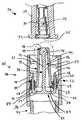
- FIG. 2is a perspective view, partially in section, of an exemplary embodiment of a self-sealing male Luer connector in accordance with aspects of the invention, including a housing having a male body disposed within a cuff, a valve plug, an elastomeric device, and a conventional female connector;
- FIG. 3is a partial cross-sectional view of the male Luer connector of FIG. 2 taken along line 3 - 3 , also showing an adjacent self-sealing female Luer connector in section;
- FIG. 4is a partial cross-sectional view of the male Luer connector of FIG. 3 with the female Luer connector partially inserted thereon;
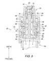
- FIG. 5is a partial cross-sectional view of the male Luer connector of FIG. 3 with the female Luer connector fully inserted thereon to activate the valve plug thereby permitting flow through the male connector;
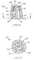
- FIG. 6is top view of the male Luer connector of FIG. 2 ;
- FIG. 7is a bottom view of the male Luer connector of FIG. 2 , with the conventional female Luer connector removed so that more details of the valve mechanism can be examined;
- FIG. 8 ais an enlarged partial cross-sectional view of the male Luer connector of FIG. 3 taken from circle ‘FIG. 8 ’ showing the distal configuration of the male body and the valve plug;
- FIG. 8 bis a partial cross-sectional view of an alternative embodiment of the distal configuration of the male body and the valve plug;
- FIG. 8 cis a partial cross-sectional view of an alternative embodiment of the distal configuration of the male body and the valve plug;
- FIG. 8 dis a partial cross-sectional view of an alternative embodiment of the distal configuration of the male body and the valve plug;
- FIG. 8 eis a partial cross-sectional view of an alternative embodiment of the distal configuration of the male body and the valve plug;
- FIG. 9is a cross-sectional view of the alternative embodiment of the distal configuration of the male body and the valve plug shown in FIG. 8 e taken along line 9 - 9 ;
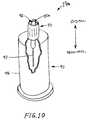
- FIG. 10is a perspective view, partially in section, of an alternative embodiment self-sealing male Luer connector, including a housing having a male body disposed within a cuff and a blood collection device.
- a connector 19having a self-sealing male connector or fitting 20 mounted on the distal end of a syringe 22 and operably connected to the proximal end of a female connector 26 configured on a patient IV interface 24 for the administration or withdrawal of fluids through the IV line 25 .
- distalrefers to the direction toward the patient
- proximalrefers to the direction away from the patient, or toward the syringe or other collection or dispensing device.
- FIG. 2there is shown a perspective view, partially in section, of an exemplary embodiment of the connector 19 of FIG. 1 having a self-sealing male connector 20 which in this case is a male Luer connector.
- the male Luer connectorincludes a housing 40 having a central distally-projecting tubular male body 42 and an outer cuff 52 interconnected with the male body by a base 56 at the proximal end 27 of the male body 42 so as to form a distally-opening cavity 61 configured for receiving a female Luer connector, such as the connector 26 shown in FIG. 3 .
- the male bodyis formed with an internal flow passage or bore 46 within which a valve element, which in this embodiment comprises a valve plug 70 , is slidably installed.
- the valve plugis generally formed with a central lengthwise stem 72 having a distal head 75 configured to sealingly engage the distal end of the flow passage that forms a flow passage opening 21 located at the distal end of the male body so as to selectively prevent fluid flow through the connector.
- At the opposite, proximal end of the valve plug 70at least one upwardly-turned activation arm 78 is configured so as to project distally into the cavity 61 through an activation opening 58 (shown in FIG. 3 ) formed in the base 56 .
- An elastomeric sealing device 90is configured within the activation opening around the activation arm in order to hold the valve plug in place within the housing and bias the valve plug distally into sealing engagement with the male body's internal flow passage.
- a conventional female Luer connector 94is formed at the proximal end 27 of the male body 42 .
- the female Luer connectorincludes thread elements 100 . It should be appreciated however that a variety of other connectors and devices, such as a shielded blood collection cannula device 95 (shown in FIG. 10 ), may be employed.
- the valve plug 70remains in its at-rest, flow stop, distal position at which it seals off the flow passage and prevents the unwanted escape of any fluids within the connector 19 and the syringe to which it is mounted ( FIG. 1 ).
- the activation arm 78 projecting distally from the proximal end of the valve plug 70is shown as extending into the female Luer connector-receiving cavity 61 beyond the elastomeric sealing device 90 so that the distal end 79 of the arm is exposed.
- a female Luer connector 26for example, that shown in FIG. 3
- the proximal end of the female connectorwill come into contact with the distal end 79 of the arm.
- proximal movement of the female connector onto the male connector to fully seatwill, in turn, proximally shift the valve plug through engagement of the activation arm with the female connector.
- proximal movement of the valve plug against the biasing force of the elastomeric deviceserves to unseat the valve plug's distal head from the distal end or flow passage opening 21 of the flow passage 46 . Because, as shown, the valve plug stem 72 is narrow relative to the flow passage bore, once the male and female connectors are connected and the valve plug has shifted proximally to unseat the head and open the flow passage opening, fluid can flow around the stem and through the connectors.
- the self-sealing male Luer connector 20closes and prevents flow therethrough when disconnected from a female connector, or the like, while it opens to a flow position and allows flow during connection.
- the male Luer connectoris thus configured to be both self-sealing and to allow needleless connection to a female Luer connector, thereby protecting both the care giver and the patient from dangerous cross-contamination before, during and after use.
- FIG. 3there is shown a partial cross-sectional view of the exemplary embodiment of the self-sealing male Luer connector 20 of the connector 19 of FIG. 2 .
- the central lengthwise stem 72 of the valve plug 70is positioned substantially coaxially within the flow passage 46 and terminates proximally in a linkage 82 defining a horizontal bar 83 on which are mounted one or more activation arms 78 at the respective opposite bar ends 84 .
- the cross-section of the valve plugis generally an upside-down capital “T”.
- the valve plugmay then be formed with two substantially opposite activation arms configured to extend parallel to the stem from opposite ends of the linkage and to be aligned with and project distally through two corresponding activation holes 58 formed in the base 56 .
- the forces serving to shift the valve plug proximallyare substantially symmetrical and balanced so as to obtain smooth, linear translation of the valve plug and, specifically, of each activation arm within its respective activation opening.
- Each activation opening 58may be defined by a radially-inwardly projecting annular flange 59 on which the elastomeric device 90 seats.
- the flangeis essentially formed by configuring the activation opening inside diameter to be smaller than the transverse dimension of the closed end of the distally-facing cavity 61 ( FIG. 2 ) defined as the difference between the nominal inside diameter of the housing cuff 52 and the outside diameter of the proximal end of the male body 42 .
- the elastomeric deviceserves to bond the valve plug 70 to the housing 40 , to seal the activation openings in the housing wall about the activation arms, and to provide a biasing spring force to keep the valve plug seated distally within the flow passage.
- the elastomeric devicemay consist of an elastomeric sealing material 91 such as Loctite® 3103 ultraviolet cured acrylic deposited within each activation opening while the respective activation arm is in position. Once cured, the elastomeric material has a high bond strength but allows substantial elongation so as to accommodate temporary proximal displacement of the valve plug during use of the male Luer connector. It also acts as a spring to bias the valve plug back to the flow stop position shown in FIG. 3 .
- the flow passage 46 formed through the tubular male body 42is shown in the exemplary embodiment male Luer connector 20 as having a distally-tapered annular inside surface 47 terminating distally in a radially-inward, proximally-facing nesting shoulder 49 so as to define a central flow passage opening 48 and act as a valve seat.
- the distal head 75 of the valve plug 70is configured to seat against the shoulder so as to achieve a surface-to-surface seal when the valve plug is forced into contact with the shoulder by a biasing device such as elastomeric device 90 .
- the valve plug's stemis configured with an outside diameter that is smaller than the nominal inside diameter of the flow passage so as to provide an annular space through which fluid can flow around the stem when the valve is opened.
- the stemis further formed having a sufficient length to space the valve plug's base 82 away from the proximally-facing surface of the housing wall 56 to provide clearance for the elastomeric device to fully seat about the annular flange 59 of the activation opening and to allow fluid flow around the base through the flow passage.
- the configuration of the housing 40 shown in FIGS. 2 and 3is well-suited for the injection molding manufacturing process, whereby the housing may be made in a relatively simple two-half mold cavity with a single core pull. Because the design of the housing is particularly suited to injection molding, then, it may be formed from a variety of plastic materials such as polyethylene, polypropylene, polycarbonate, PVC, ABS, acrylic and K-resin. Similarly, the valve plug 70 is also conveniently fabricated using a conventional injection molding process as is known and practiced in the art and thus may also be formed from a wide variety of plastics. As such, the male Luer connector is readily manufacturable with few moving parts.
- the conventional female Luer connector 94that is disposed at the proximal end of the male connector body and which extends proximally from the male Luer connector's housing 40 is shown in the exemplary embodiment as a separate component having its distal end press-fit within the housing's proximal end.
- the female Luer connectorlike the housing and the valve plug 70 , may be formed through an injection molding process and subsequently installed on the housing a variety of assembly techniques now known or later developed in the art, including a press- or interference-fit, solvent bonding, or ultrasonic welding.
- the housingis of sufficient length proximal of the housing wall 56 such that the female Luer connector or other medical device can be installed proximally while leaving enough space between the distal end of the female Luer connector and the base 82 of the valve plug to allow the valve plug to translate proximally when the male Luer connector is connected to a patient's IV interface female connector 26 during use for example.
- the distal end 36 of the female Luer connector 94may be configured to support a compression spring or the like which, when installed within the housing between the female Luer connector 94 and the base of the valve plug 82 , may cooperate with the elastomeric device 90 to bias the valve plug distally so as to maintain a bias tending to maintain a seal between the valve plug head 75 and the flow passage distal shoulder 49 .
- the female Luer connector 26 of a patient's IV interface 24 ( FIG. 1 ) shown adjacent the distal end of the male Luer connector 20is generally configured with a tubular barrel 28 having a distally-tapered interior surface 30 formed according to ANSI/AAMI/ISO standard 594.1 for medical connectors.
- the inner surfacetapers inward in the distal direction from a larger diameter to a smaller diameter.
- a self-sealing piston 34may be installed within the barrel having a selectively openable opening 35 responsive to compression of the piston upon insertion of a male Luer connector to open the opening and allow fluid flow through the female Luer connector. As will be discussed more fully below regarding FIGS.
- the male body 42 of the self-sealing male Luer connector 20is formed with a distally-tapered exterior surface 44 that tapers in the distal direction from a larger diameter to a smaller diameter, configured to sealingly engage the tapered inside surface of the female Luer connector when the two connectors are mated.
- FIG. 4there is shown a partial cross-sectional view of the self-sealing male Luer connector 20 with the female Luer connector 26 partially inserted thereon.
- the valve element 75 of the connector 19remains in the flow stop position.
- the female Luer connector's tubular barrel 28has been advanced proximally within the cavity 61 onto the male body 42 until the proximally-facing barrel abutment surface 29 has just come into contact with the distal ends 79 of the respective activation arms 78 .
- the female Luer connectorhas not yet shifted the valve plug 70 proximally, so the distal head 75 remains in sealing engagement within the flow passage 46 due to the biasing force of the elastomeric device 90 mounted within the activation openings 58 about the valve plug's activation arms.
- the tubular male bodyhas passed a sufficient distance within the female Luer connector's barrel to begin to form a taper-to-taper surface seal between the male body's outside surface 44 and the barrel's inside surface 30 .
- the passage of the distal end of the male body into the barrelhas served to compress the self-sealing piston 34 and thereby open the opening 35 .
- the male Luer connectoris so configured that upon partial connection with a self-sealing female Luer connector, the two connectors begin to seal along their corresponding distally-tapered surfaces and the self-sealing piston is activated before any fluid flow through the male Luer connector is allowed.
- the male Luer connector in accordance with the present inventionprovides for safe and effective needleless connection to a self-sealing female Luer connector with minimized risk of fluid escape by essentially causing the female Luer connector to be activated before the male Luer connector is activated through further proximal movement of the female Luer connector.
- FIG. 5there is shown a partial cross-sectional view of the female Luer connector 26 fully inserted onto the self-sealing male Luer connector 20 .
- the valve plug 70has shifted proximally with the further proximal movement of the female Luer connector against the biasing force of the elastomeric sealing device 90 to unseat the distal head 75 from the shoulder 49 and allow flow through the flow passage 46 , thereby now activating the male Luer connector.
- the valve elementis thus in the flow position.
- the elastomeric material 91 comprising the sealing deviceremains bonded to both the activation arms and the activation openings 58 as it stretches proximally with the proximal movement of the entire valve plug.
- the bond strength of an ultraviolet cured acrylic or the like as the elastomeric materialmay alone be sufficient to resist the forces applied by the proximal movement of the female Luer connector
- the radially-inward flanges 59 formed about each activation openingprovide a seat on which the elastomeric device can anchor, thereby improving the device's strength and its ability to remain installed within the activation openings about the activation arms even under load.
- the fluidwill flow through the female Luer connector's piston 34 , its opening 35 , the central flow passage opening 48 at the distal end of the flow passage 46 , through the flow passage itself by passing around the distal head 75 and stem 72 of the valve plug, out the proximal end of the flow passage opening and through the flow openings 86 created by the space between the base 82 of the valve plug and the proximal housing wall 56 , and through the proximal female Luer connector 94 into the syringe 22 ( FIG. 1 ).
- the same flow pathwould be followed in reverse if medicines or other fluids are being dispensed from the syringe into the patient's IV line 25 ( FIG. 1 ).
- the female Luer connectormay then simply be disconnected from the male Luer connector, whereby the respective self-sealing devices would then reseal in the reverse order. That is, as the female Luer connector is withdrawn distally from the male Luer connector, the valve plug will reseal first under the biasing force exerted by the elastomeric device 90 when the female Luer connector reaches the position shown in FIG. 4 .
- the male Luer connectoris easy to wipe and keep sanitary, as all engagement surfaces are exposed and easily accessible upon disconnection of the device from the female connector.
- the activation arms 78 , and their linkage 82 and 83thus form a valve element control device, with the arms disposed external to the male connector body adjacent the proximal end of the male connector body and being movable towards the proximal end, to control movement of the valve element to the flow position and being movable toward the distal end to control movement of the valve element to the flow stop position.
- the female Luer connector 26may be formed on the proximal end of its tubular barrel 28 with external thread elements or portions 32 as is known in the art. Accordingly, the inside surface 53 of the male Luer connector housing 40 's cuff 52 may be formed with internal threads 54 configured to threadably engage the female Luer connector's external thread portions and thereby pull and secure the female connector in sealing engagement with the male connector.
- FIG. 6there is seen a top view of the male Luer connector 20 of FIG. 2 .
- the orientation of the respective opposite activation arms 78 spaced about the male body and extending into the cavity from the housing's proximal wall 56is only one of various arrangements possible in accordance with aspects of the present invention.
- FIG. 7there is shown a bottom view of the male Luer connector of FIG. 2 , with the proximally-projecting female Luer connector 94 ( FIG. 2 ) removed for clarity in illustrating the relevant elements.
- the linkage 82 of the valve plug 70( FIG. 3 ) is configured as a substantially linear bar 83 extending symmetrically in opposite directions away from the proximal end of the stem 72 so as to position the respective bar ends 84 substantially beneath the activation openings 58 ( FIG. 3 ) so that the activation arms 78 ( FIG. 3 ) extending distally away from the bar ends can freely translate within the activation openings.
- the flow passage 46is unhindered proximally by the base, allowing flow around the base with the valve plug in any position within the male body 42 ( FIGS. 2-6 ), while the far, distal end of the flow passage is sealed off by the distal head 75 with the valve plug in the distally-biased position shown.
- the plugwill be inserted from the bottom as in FIG. 7 and then the activation arms will be bonded in place within the activation openings by inserting the elastomeric device 90 in and about the openings so as to essentially pot the valve plug in position within the valve with the distal head sealingly seated in the distal end of the flow passage.
- FIGS. 8 a - 8 ethere are shown enlarged partial cross-sectional views of various exemplary embodiments of the configuration of the distal end of the male body 42 's flow passage 46 and the corresponding configuration of the valve plug 70 's stem 72 and distal head 75 so as to selectively seal within the flow passage as discussed above. It is to be understood that these embodiments are exemplary only and that a variety of sealing arrangements are possible.
- FIG. 8 athere is seen the exemplary configuration of the male Luer connector 20 shown in FIGS. 2-7 wherein the flow passage has a distally-tapered interior surface 47 that terminates distally in a in a radially-inward, proximally-facing nesting shoulder 49 .
- the shouldermay be configured as a proximally-facing first frusto-conical surface 50 .
- the distal headis configured with a distally-facing second frusto-conical surface 76 so as to correspond to the first frusto-conical surface.
- the valve plugis formed as a unitary structure from a single material.
- the stem and headmay both be injection molded from a semirigid thermoplastic such that the stem has the necessary mechanical integrity to transmit the force exerted by the elastomeric device 90 ( FIGS.
- FIG. 8 bthere is shown a male body 42 and valve plug 70 a quite similar to that of FIG. 8 a , with the exception that the stem 72 a and head 75 a are not formed of one material in a unitary construction. Rather, the stem is formed again of a rigid or semi-rigid material but is configured at its distal end with a distal flange 73 . The head is then overmolded onto the distal end of the stem about the distal flange. In this way, it will be appreciated that the head may be made of a resilient, flexible material so as to seal within the distal end of the flow passage 46 .
- the material of the headmay be selected from a number of medical grade silicon rubbers, thermoplastic elastomers, and thermoplastic vulcanates.
- the headmay be slightly oversized relative to the distal end of the flow passage so as to slightly compress the head when the valve plug is biased distally by the elastomeric sealing device 90 ( FIGS. 2 and 3 ) and thereby insure a positive seal when the male Luer connector is disconnected or is otherwise not in use.
- a resilient headcould be molded in a separate operation and mounted onto the valve stem using other assembly techniques now know or later developed in the art, such as solvent bonding or snap- or press-fit.
- FIGS. 8 c and 8 dan alternative configuration for the radially-inwardly extending nesting shoulder 49 a of the tubular male body 42 a is shown wherein the shoulder is generally an annular flange that is perpendicular to the body's axis so as to form a squared proximally-facing sealing surface 50 a .
- the annular flangedefines a central flow passage opening 48 a through which fluids can selectively pass from a female Luer connector 26 ( FIG. 5 ) into the male Luer connector's flow passage 46 a .
- the valve plug 70 bis shown as having a generally “T”-shaped cross-section formed by a vertical stem 72 b and a horizontal distal head 75 b .
- the distally-facing head sealing surface 76 bis brought into surface-to-surface contact with the shoulder's proximally-facing sealing surface so as to create a face seal and prevent fluid flow through the connector.
- the straight-walled side surface 77 bagain allows fluid flow between the head and the distally-tapered interior surface 47 a of the flow passage.
- the distal head 75 cmay be configured with a substantially planar, distally-facing sealing surface 76 c configured to create a face seal against the nesting shoulder 49 a 's proximally-facing sealing surface 50 a when the valve plug 70 c is biased distally within the flow passage 46 a .
- a distally-projecting head plug 98may be configured on the head's distally-facing surface so as to effectively plug and seal within the central flow passage opening 48 a . In this way, more surface-to-surface engagement is provided to further effectuate a positive seal between the valve plug head and the distal end of the flow passage.
- the distal end of the head plugmay be rounded to facilitate centering and seating the head plug within the flow passage opening.
- the side surface 77 c of the headmay be proximally-tapered or radiused inwardly to provide further clearance between the head and the interior surface 47 a of the flow passage when the valve is activated.
- FIG. 8 ethere is shown an alternative configuration of the tubular male body 42 b in which the flow passage 46 b is formed having a substantially straight-walled interior surface 47 b parallel with the flow passage's central axis.
- the flow passageagain terminates distally in a radially-inwardly-projecting, distally-tapered nesting shoulder 49 b defining a central flow passage opening 48 b and a proximally-facing first frusto-conical surface 50 b .
- Due to the non-tapered interior surface of the flow passageit will be appreciated by those skilled in the art that the previous exemplary valve plug and head configurations will not effectively open the flow passage when the valve plug is shifted proximally upon connection to a female Luer connector 26 ( FIG.
- the distal head 75 d of the exemplary embodiment of FIG. 8 eis configured with a central solid portion having lengthwise ribs 99 spaced thereabout to allow for fluid communication around the head once the distal end of the head has unseated from the distal end of the flow passage.
- the central portion of the headis formed distally with a distally-facing second frusto-conical surface configured to sealingly engage the shoulder's first frusto-conical surface when the valve plug is biased distally within the flow passage, much like the sealing engagement of the exemplary embodiments of FIGS. 8 a and 8 b . Then, when the valve plug is shifted proximally during connection with a female Luer connector, the first and second frusto-conical surfaces are disengaged to allow flow through the central flow passage opening into the flow passage.
- fluid flowcan continue through the flow passage 46 b around the valve plug's distal head 75 d by passing about the head's solid portion between the circumferentially spaced-apart ribs 99 and then around the narrower stem 72 d and on through the connector as described previously.
- the ribsserve as spacers to space the solid central portion of the distal head away from the interior surface 47 b of the flow passage, thereby allowing fluid flow around the head.
- the ribsfurther serve to keep the stem and head centered within the flow passage as the valve plug 70 d translates axially therein during use of the male Luer connector. It is noted that the taper-to-taper engagement between the distal head and the shoulder 49 b ( FIG.
- valve plug 8 ecan alone serve to center the head as it seats in the distal end of the flow passage so as to effectively close the flow passage opening and that this function in combination with the stiffness of the stem may allow for the activation of the valve within a straight-walled flow passage without the use of the ribbed spacers.
- FIGS. 8 a - 8 eare merely illustrative of selectively sealable arrangements for the respective engaging components that are possible and are in no way limiting of the scope of the present invention.
- the exemplary embodiment male Luer connectors of FIGS. 8 c - 8 emay also be configured with the valve plug having a single, unitary construction or with the stem of a rigid or semi-rigid plastic and a resilient head overmolded or otherwise mounted onto the stem's distal end.
- FIG. 10there is shown an alternative embodiment of a connector 19 a having a male Luer connector 20 a having a blood collection device 95 mounted opposite the housing 40 .
- the blood collection devicewhich is known and used in the art, includes a proximally-extending needle cannula 97 and a shield 96 mounted about the needle so as to protect care givers and patients from accidental needle punctures.
- the connector's male body 42may be connected to the female Luer connector 26 of a patient's IV interface 24 ( FIG. 1 ), as discussed above, to activate the internal valve plug 70 ( FIG. 2 ) and create a needle-free flow path between the patient's IV line 25 ( FIG. 1 ) and the needle through the male Luer connector.
- a resilient boot (not shown) over the needleprevents the flow of fluid through the needle until a vacuumized blood collection vial with septum (not shown) is inserted within the blood collection device shield to push the boot up the needle while the needle then penetrates the septum to allow fluid to flow therethrough into the vial.
- the vialWhen the vial is full, it may be removed from the blood collection device and another installed therein until the desired quantity of blood has been withdrawn. Then, the male connector may simply be disconnected from the female connector on the patient's IV line and discarded.
- the self-sealing internal valve plug operably installed within the male connectorserves to safely and easily connect to and disconnect from the female Luer connector of a patient's IV line for the effective and controlled administration and/or withdrawal of fluids.
- the male Luer connectoris well-suited for connection to a syringe or other device used to transfer fluids to and from a patient without compromising the patient's or the care giver's safety. While particular forms of the invention have been illustrated and described, it will also be apparent to those skilled in the art that various modifications can be made without departing from the spirit and scope of the invention. Accordingly, it is not intended that the invention be limited except by the appended claims.
Landscapes
- Health & Medical Sciences (AREA)
- Life Sciences & Earth Sciences (AREA)
- Heart & Thoracic Surgery (AREA)
- Engineering & Computer Science (AREA)
- Animal Behavior & Ethology (AREA)
- Hematology (AREA)
- Veterinary Medicine (AREA)
- Biomedical Technology (AREA)
- Public Health (AREA)
- General Health & Medical Sciences (AREA)
- Molecular Biology (AREA)
- Pathology (AREA)
- Medical Informatics (AREA)
- Physics & Mathematics (AREA)
- Biophysics (AREA)
- Surgery (AREA)
- Pulmonology (AREA)
- Anesthesiology (AREA)
- Manufacturing & Machinery (AREA)
- Infusion, Injection, And Reservoir Apparatuses (AREA)
- Quick-Acting Or Multi-Walled Pipe Joints (AREA)
- Water Treatment By Sorption (AREA)
- Feeding And Controlling Fuel (AREA)
- External Artificial Organs (AREA)
- Medical Preparation Storing Or Oral Administration Devices (AREA)
- Replacement Of Web Rolls (AREA)
- Sealing Devices (AREA)
Abstract
Description
Claims (27)
Priority Applications (1)
| Application Number | Priority Date | Filing Date | Title |
|---|---|---|---|
| US11/563,647US7766304B2 (en) | 2002-12-31 | 2006-11-27 | Self-sealing male luer connector with biased valve plug |
Applications Claiming Priority (2)
| Application Number | Priority Date | Filing Date | Title |
|---|---|---|---|
| US10/335,242US7140592B2 (en) | 2002-12-31 | 2002-12-31 | Self-sealing male Luer connector with biased valve plug |
| US11/563,647US7766304B2 (en) | 2002-12-31 | 2006-11-27 | Self-sealing male luer connector with biased valve plug |
Related Parent Applications (1)
| Application Number | Title | Priority Date | Filing Date |
|---|---|---|---|
| US10/335,242DivisionUS7140592B2 (en) | 2002-12-31 | 2002-12-31 | Self-sealing male Luer connector with biased valve plug |
Publications (2)
| Publication Number | Publication Date |
|---|---|
| US20090030401A1 US20090030401A1 (en) | 2009-01-29 |
| US7766304B2true US7766304B2 (en) | 2010-08-03 |
Family
ID=32655297
Family Applications (2)
| Application Number | Title | Priority Date | Filing Date |
|---|---|---|---|
| US10/335,242Expired - LifetimeUS7140592B2 (en) | 2002-12-31 | 2002-12-31 | Self-sealing male Luer connector with biased valve plug |
| US11/563,647Expired - LifetimeUS7766304B2 (en) | 2002-12-31 | 2006-11-27 | Self-sealing male luer connector with biased valve plug |
Family Applications Before (1)
| Application Number | Title | Priority Date | Filing Date |
|---|---|---|---|
| US10/335,242Expired - LifetimeUS7140592B2 (en) | 2002-12-31 | 2002-12-31 | Self-sealing male Luer connector with biased valve plug |
Country Status (16)
| Country | Link |
|---|---|
| US (2) | US7140592B2 (en) |
| EP (2) | EP1578478B1 (en) |
| JP (1) | JP4738815B2 (en) |
| CN (1) | CN100475286C (en) |
| AT (2) | ATE547146T1 (en) |
| AU (1) | AU2003300270B2 (en) |
| CA (1) | CA2511971C (en) |
| CY (1) | CY1112408T1 (en) |
| DK (1) | DK1578478T3 (en) |
| ES (2) | ES2371504T3 (en) |
| NO (1) | NO20053319L (en) |
| NZ (1) | NZ540995A (en) |
| PL (2) | PL209774B1 (en) |
| PT (1) | PT1578478E (en) |
| WO (1) | WO2004060474A1 (en) |
| ZA (1) | ZA200505228B (en) |
Cited By (70)
| Publication number | Priority date | Publication date | Assignee | Title |
|---|---|---|---|---|
| US20060079853A1 (en)* | 2004-10-12 | 2006-04-13 | C. R. Bard, Inc. | Corporeal drainage system |
| US20100270792A1 (en)* | 2009-04-23 | 2010-10-28 | Fresenius Medical Care Deutschland Gmbh | Connection means and method for connecting at least two fluid-conducting medical-technical systems, as well as medical-technical apparatus |
| US8066692B2 (en) | 2003-12-30 | 2011-11-29 | Icu Medical, Inc. | Medical male luer connector with increased closing volume |
| US8177772B2 (en) | 2005-09-26 | 2012-05-15 | C. R. Bard, Inc. | Catheter connection systems |
| US8211069B2 (en) | 2005-07-06 | 2012-07-03 | Icu Medical, Inc. | Medical connector with closeable male luer |
| US8414555B2 (en) | 2008-05-14 | 2013-04-09 | J & J Solutions, Inc. | Systems and methods for safe medicament transport |
| US20130306676A1 (en)* | 2012-05-21 | 2013-11-21 | The Coca-Cola Company | Bag in Box Cleanable Connector System |
| US20130327794A1 (en)* | 2012-05-21 | 2013-12-12 | The Coca-Cola Company | Bag in Box Cleanable Connector System Having Conical Plunger |
| US8608723B2 (en) | 2009-11-12 | 2013-12-17 | Medimop Medical Projects Ltd. | Fluid transfer devices with sealing arrangement |
| US8628516B2 (en) | 2009-03-22 | 2014-01-14 | Elcam Medical Agricultural Cooperative Association Ltd. | Closed male luer connector |
| US8636721B2 (en) | 2003-11-20 | 2014-01-28 | Henry M. Jackson Foundation For The Advancement Of Military Medicine, Inc. | Portable hand pump for evacuation of fluids |
| US8647310B2 (en) | 2010-05-06 | 2014-02-11 | Icu Medical, Inc. | Medical connector with closeable luer connector |
| US8679090B2 (en) | 2008-12-19 | 2014-03-25 | Icu Medical, Inc. | Medical connector with closeable luer connector |
| US8684994B2 (en) | 2010-02-24 | 2014-04-01 | Medimop Medical Projects Ltd. | Fluid transfer assembly with venting arrangement |
| US20140107612A1 (en)* | 2011-04-18 | 2014-04-17 | Intravena, Llc | Protection against spill and syringe related contamination |
| US8753325B2 (en) | 2010-02-24 | 2014-06-17 | Medimop Medical Projects, Ltd. | Liquid drug transfer device with vented vial adapter |
| US8752598B2 (en) | 2011-04-17 | 2014-06-17 | Medimop Medical Projects Ltd. | Liquid drug transfer assembly |
| US8852145B2 (en) | 2010-11-14 | 2014-10-07 | Medimop Medical Projects, Ltd. | Inline liquid drug medical device having rotary flow control member |
| US8905994B1 (en) | 2011-10-11 | 2014-12-09 | Medimop Medical Projects, Ltd. | Valve assembly for use with liquid container and drug vial |
| USD720451S1 (en) | 2012-02-13 | 2014-12-30 | Medimop Medical Projects Ltd. | Liquid drug transfer assembly |
| US8974437B2 (en) | 2011-07-28 | 2015-03-10 | Applied Medical Technology, Inc. | Coupling for medical fluids |
| US8979792B2 (en) | 2009-11-12 | 2015-03-17 | Medimop Medical Projects Ltd. | Inline liquid drug medical devices with linear displaceable sliding flow control member |
| US8998875B2 (en) | 2009-10-01 | 2015-04-07 | Medimop Medical Projects Ltd. | Vial assemblage with vial and pre-attached fluid transfer device |
| USD734868S1 (en) | 2012-11-27 | 2015-07-21 | Medimop Medical Projects Ltd. | Drug vial adapter with downwardly depending stopper |
| US9107809B2 (en) | 2010-05-27 | 2015-08-18 | J & J Solutions, Inc. | Closed fluid transfer system |
| US9114242B2 (en) | 2005-07-06 | 2015-08-25 | Icu Medical, Inc. | Medical connector |
| USD737436S1 (en) | 2012-02-13 | 2015-08-25 | Medimop Medical Projects Ltd. | Liquid drug reconstitution assembly |
| US9168366B2 (en) | 2008-12-19 | 2015-10-27 | Icu Medical, Inc. | Medical connector with closeable luer connector |
| US9283324B2 (en) | 2012-04-05 | 2016-03-15 | Medimop Medical Projects, Ltd | Fluid transfer devices having cartridge port with cartridge ejection arrangement |
| US9295827B2 (en) | 2013-04-29 | 2016-03-29 | Gale Harrison Thorne | Twisted slit valve |
| US9339438B2 (en) | 2012-09-13 | 2016-05-17 | Medimop Medical Projects Ltd. | Telescopic female drug vial adapter |
| USD757933S1 (en) | 2014-09-11 | 2016-05-31 | Medimop Medical Projects Ltd. | Dual vial adapter assemblage |
| USD765837S1 (en) | 2013-08-07 | 2016-09-06 | Medimop Medical Projects Ltd. | Liquid transfer device with integral vial adapter |
| USD767124S1 (en) | 2013-08-07 | 2016-09-20 | Medimop Medical Projects Ltd. | Liquid transfer device with integral vial adapter |
| US9775981B2 (en) | 2013-03-15 | 2017-10-03 | Icu Medical, Inc. | Medical connector |
| US9795536B2 (en) | 2012-08-26 | 2017-10-24 | Medimop Medical Projects, Ltd. | Liquid drug transfer devices employing manual rotation for dual flow communication step actuations |
| USD801522S1 (en) | 2015-11-09 | 2017-10-31 | Medimop Medical Projects Ltd. | Fluid transfer assembly |
| US9801786B2 (en) | 2013-04-14 | 2017-10-31 | Medimop Medical Projects Ltd. | Drug container closure for mounting on open-topped drug container to form drug reconstitution assemblage for use with needleless syringe |
| US9839580B2 (en) | 2012-08-26 | 2017-12-12 | Medimop Medical Projects, Ltd. | Liquid drug transfer devices |
| US9877895B2 (en) | 2013-08-02 | 2018-01-30 | J&J Solutions, Inc. | Compounding systems and methods for safe medicament transport |
| US9933094B2 (en) | 2011-09-09 | 2018-04-03 | Icu Medical, Inc. | Medical connectors with fluid-resistant mating interfaces |
| US9943463B2 (en) | 2013-05-10 | 2018-04-17 | West Pharma. Services IL, Ltd. | Medical devices including vial adapter with inline dry drug module |
| US9950114B2 (en) | 2011-05-13 | 2018-04-24 | Thorne Consulting For International Property, Llc | Dual-chamber syringe and associated connecting systems |
| USD832430S1 (en) | 2016-11-15 | 2018-10-30 | West Pharma. Services IL, Ltd. | Dual vial adapter assemblage |
| US10278897B2 (en) | 2015-11-25 | 2019-05-07 | West Pharma. Services IL, Ltd. | Dual vial adapter assemblage including drug vial adapter with self-sealing access valve |
| US10285907B2 (en) | 2015-01-05 | 2019-05-14 | West Pharma. Services IL, Ltd. | Dual vial adapter assemblages with quick release drug vial adapter for ensuring correct usage |
| US10357429B2 (en) | 2015-07-16 | 2019-07-23 | West Pharma. Services IL, Ltd. | Liquid drug transfer devices for secure telescopic snap fit on injection vials |
| US10646404B2 (en) | 2016-05-24 | 2020-05-12 | West Pharma. Services IL, Ltd. | Dual vial adapter assemblages including identical twin vial adapters |
| US10688295B2 (en) | 2013-08-07 | 2020-06-23 | West Pharma. Services IL, Ltd. | Liquid transfer devices for use with infusion liquid containers |
| US10765604B2 (en) | 2016-05-24 | 2020-09-08 | West Pharma. Services IL, Ltd. | Drug vial adapter assemblages including vented drug vial adapter and vented liquid vial adapter |
| US10772798B2 (en) | 2016-12-06 | 2020-09-15 | West Pharma Services Il, Ltd. | Liquid transfer device with integral telescopic vial adapter for use with infusion liquid container and discrete injection vial |
| US10806671B2 (en) | 2016-08-21 | 2020-10-20 | West Pharma. Services IL, Ltd. | Syringe assembly |
| US10806667B2 (en) | 2016-06-06 | 2020-10-20 | West Pharma. Services IL, Ltd. | Fluid transfer devices for filling drug pump cartridges with liquid drug contents |
| USD903864S1 (en) | 2018-06-20 | 2020-12-01 | West Pharma. Services IL, Ltd. | Medication mixing apparatus |
| US20200377841A1 (en)* | 2019-05-30 | 2020-12-03 | Ge Healthcare Bio-Sciences Corp. | System, method and apparatus for draining a bioreactor vessel |
| US10888496B2 (en) | 2015-09-17 | 2021-01-12 | Corvida Medical, Inc. | Medicament vial assembly |
| US10894317B2 (en) | 2015-10-13 | 2021-01-19 | Corvida Medical, Inc. | Automated compounding equipment for closed fluid transfer system |
| US10945921B2 (en) | 2017-03-29 | 2021-03-16 | West Pharma. Services IL, Ltd. | User actuated liquid drug transfer devices for use in ready-to-use (RTU) liquid drug transfer assemblages |
| USD917693S1 (en) | 2018-07-06 | 2021-04-27 | West Pharma. Services IL, Ltd. | Medication mixing apparatus |
| USD923812S1 (en) | 2019-01-16 | 2021-06-29 | West Pharma. Services IL, Ltd. | Medication mixing apparatus |
| USD923782S1 (en) | 2019-01-17 | 2021-06-29 | West Pharma. Services IL, Ltd. | Medication mixing apparatus |
| US11344318B2 (en) | 2016-07-18 | 2022-05-31 | Merit Medical Systems, Inc. | Inflatable radial artery compression device |
| USD954253S1 (en) | 2019-04-30 | 2022-06-07 | West Pharma. Services IL, Ltd. | Liquid transfer device |
| USD956958S1 (en) | 2020-07-13 | 2022-07-05 | West Pharma. Services IL, Ltd. | Liquid transfer device |
| US20230078397A1 (en)* | 2021-09-13 | 2023-03-16 | Carefusion 303, Inc. | Adjustable pressure regulating and pressure indicating needle-free connectors |
| US11642285B2 (en) | 2017-09-29 | 2023-05-09 | West Pharma. Services IL, Ltd. | Dual vial adapter assemblages including twin vented female vial adapters |
| US11918542B2 (en) | 2019-01-31 | 2024-03-05 | West Pharma. Services IL, Ltd. | Liquid transfer device |
| US12274670B2 (en) | 2019-04-09 | 2025-04-15 | West Pharma. Services IL, Ltd. | Liquid transfer device with integrated syringe |
| US12427091B2 (en) | 2019-01-18 | 2025-09-30 | West Pharma. Services IL, Ltd. | Liquid transfer devices for use with intravenous (IV) bottles |
| US12426864B2 (en) | 2021-06-18 | 2025-09-30 | Merit Medical Systems, Inc. | Hemostasis devices and methods of use |
Families Citing this family (132)
| Publication number | Priority date | Publication date | Assignee | Title |
|---|---|---|---|---|
| US6695817B1 (en) | 2000-07-11 | 2004-02-24 | Icu Medical, Inc. | Medical valve with positive flow characteristics |
| US7040598B2 (en)* | 2003-05-14 | 2006-05-09 | Cardinal Health 303, Inc. | Self-sealing male connector |
| US7634558B1 (en) | 2003-09-22 | 2009-12-15 | Sprint Spectrum L.P. | Method and system for updating network presence records at a rate dependent on network load |
| US20050154368A1 (en)* | 2003-11-21 | 2005-07-14 | Vasogen Ireland Limited | Medical material handling systems |
| US7600530B2 (en) | 2004-08-09 | 2009-10-13 | Medegen, Inc. | Connector with check valve and method of use |
| US10478607B2 (en) | 2004-08-09 | 2019-11-19 | Carefusion 303, Inc. | Connector for transferring fluid and method of use |
| US7306566B2 (en)* | 2004-09-15 | 2007-12-11 | Cardinal Health 303, Inc. | Needle free blood collection device with male connector valve |
| US20060058734A1 (en)* | 2004-09-15 | 2006-03-16 | Phillips John C | Self-sealing male Luer connector with molded elastomeric tip |
| US20060161115A1 (en) | 2004-11-05 | 2006-07-20 | Fangrow Thomas F | Soft-grip medical connector |
| US7645274B2 (en)* | 2004-12-10 | 2010-01-12 | Cardinal Health 303, Inc. | Self-sealing male luer connector with multiple seats |
| US7651481B2 (en)* | 2004-12-30 | 2010-01-26 | CareFusion 303 Inc. | Self-sealing male connector device with collapsible body |
| EP1848913B1 (en)* | 2005-02-14 | 2013-07-10 | Industrie Borla S.p.A. | Valved fluid connector |
| US20060270997A1 (en)* | 2005-05-19 | 2006-11-30 | Vasogen Ireland Limited | Permission-based material dispenser |
| ITMO20050141A1 (en)* | 2005-06-09 | 2006-12-10 | Aries S R L | CLOSING DEVICE FOR CONTAINERS OR LINES OF ADMINISTRATION OF MEDICINAL OR FERMACEUTICAL FLUIDS. |
| US7448653B2 (en) | 2005-06-10 | 2008-11-11 | Value Plastics, Inc. | Female connector for releasable coupling with a male connector defining a fluid conduit |
| DE102005026986A1 (en)† | 2005-06-10 | 2006-12-14 | Robert Bosch Gmbh | Device for filling and closing containers |
| ITTO20050515A1 (en)* | 2005-07-25 | 2007-01-26 | Borla Ind | MEDICAL VALVE CONNECTOR |
| JP2007143813A (en)* | 2005-11-28 | 2007-06-14 | Nippon Sherwood Medical Industries Ltd | Medical stopcock |
| AU2006331039B2 (en)* | 2005-12-28 | 2012-01-12 | Cardinal Health 529, Llc | Male luer connector |
| US7766897B2 (en)* | 2006-01-02 | 2010-08-03 | Carefusion 303, Inc. | Protective priming cap for self-sealing male Luer valve |
| US7806139B2 (en) | 2006-01-20 | 2010-10-05 | Value Plastics, Inc. | Fluid conduit coupling assembly having male and female couplers with integral valves |
| JP5161457B2 (en)* | 2006-04-03 | 2013-03-13 | 日本コヴィディエン株式会社 | Male luer connector |
| CA2652206C (en) | 2006-05-25 | 2014-02-11 | Bayer Healthcare Llc | Reconstitution device |
| US8292875B2 (en) | 2006-09-12 | 2012-10-23 | Clay Kennard | Fluid delivery device |
| US8257286B2 (en)* | 2006-09-21 | 2012-09-04 | Tyco Healthcare Group Lp | Safety connector apparatus |
| US7981090B2 (en) | 2006-10-18 | 2011-07-19 | Baxter International Inc. | Luer activated device |
| US8221363B2 (en) | 2006-10-18 | 2012-07-17 | Baxter Healthcare S.A. | Luer activated device with valve element under tension |
| US7753338B2 (en) | 2006-10-23 | 2010-07-13 | Baxter International Inc. | Luer activated device with minimal fluid displacement |
| BRPI0717401A2 (en) | 2006-10-25 | 2013-11-12 | Icu Medical Inc | CONNECTOR FOR MEDICAL USE |
| JP4959350B2 (en) | 2007-01-19 | 2012-06-20 | 日本コヴィディエン株式会社 | Male luer connector |
| US9149573B2 (en) | 2007-03-16 | 2015-10-06 | Smiths Medical Asd, Inc. | Blunt cannula for accessing a slit septum |
| USD571006S1 (en) | 2007-03-23 | 2008-06-10 | Smiths Medical Asd, Inc. | Oval tapering blunt cannula proximal portion |
| USD571464S1 (en)* | 2007-03-23 | 2008-06-17 | Smiths Medical Asd, Inc. | Knife edge tapering blunt cannula proximal portion |
| US8006953B2 (en)* | 2007-05-17 | 2011-08-30 | Lavon Bennett | Luer hub connector |
| US8603029B2 (en)* | 2007-10-10 | 2013-12-10 | Hospi Corporation | Apparatuses and methods for medication administration |
| ITTO20070141U1 (en)* | 2007-11-14 | 2009-05-15 | Borla Ind | SYRINGE |
| USD654573S1 (en) | 2007-11-19 | 2012-02-21 | Value Plastics, Inc. | Female quick connect fitting |
| CA2717754C (en)* | 2008-03-04 | 2017-06-06 | Infusion Innovations, Inc. | Devices, assemblies, and methods for controlling fluid flow |
| US8257287B2 (en) | 2008-03-20 | 2012-09-04 | Tyco Healthcare Group Lp | Safety connector assembly |
| US9408971B2 (en)* | 2008-03-31 | 2016-08-09 | Covidien Lp | Self-capping syringe assembly with one-way valve |
| US20090306544A1 (en) | 2008-06-09 | 2009-12-10 | Ho-Kin Ng | Instillation/aspiration device |
| US20090301480A1 (en)* | 2008-06-09 | 2009-12-10 | Mamdouh Elsakka | Diagnostic sample collection system and method of use |
| CA2670556C (en)* | 2008-06-30 | 2013-02-19 | Tyco Healthcare Group Lp | Discriminating oral tip adaptor |
| US8235426B2 (en) | 2008-07-03 | 2012-08-07 | Nordson Corporation | Latch assembly for joining two conduits |
| US8060089B1 (en) | 2008-09-22 | 2011-11-15 | Sprint Spectrum L.P. | Paging success rate control mechanism |
| US9775980B2 (en) | 2008-09-23 | 2017-10-03 | Hospi Corporation | Valved enteral administration assembly |
| US9078992B2 (en) | 2008-10-27 | 2015-07-14 | Pursuit Vascular, Inc. | Medical device for applying antimicrobial to proximal end of catheter |
| US8206375B2 (en)* | 2009-02-07 | 2012-06-26 | Merit Medical Systems, Inc. | Valved connector |
| US8523826B2 (en)* | 2009-02-13 | 2013-09-03 | Cytyc Corporation | Luer-type needle-free valve fitting with bypass |
| US8454579B2 (en) | 2009-03-25 | 2013-06-04 | Icu Medical, Inc. | Medical connector with automatic valves and volume regulator |
| US8182452B2 (en)* | 2009-04-06 | 2012-05-22 | Carefusion 303, Inc. | Closed male luer device for use with needleless access devices |
| US8057095B2 (en)* | 2009-04-23 | 2011-11-15 | Medtronic, Inc. | Multiple use temperature monitor adapter, system and method of using same |
| EP2251061B1 (en)* | 2009-05-11 | 2018-04-18 | Kpr U.S., Llc | Discriminating fluid connection system |
| USD655393S1 (en) | 2009-06-23 | 2012-03-06 | Value Plastics, Inc. | Multi-port valve |
| USD616985S1 (en)* | 2009-06-26 | 2010-06-01 | Abbott Point Of Care Inc. | Dispensing tip |
| USD627065S1 (en)* | 2009-06-26 | 2010-11-09 | Abbott Point Of Care Inc. | Dispensing tip and cap |
| USD650478S1 (en) | 2009-12-23 | 2011-12-13 | Value Plastics, Inc. | Female dual lumen connector |
| USD649240S1 (en) | 2009-12-09 | 2011-11-22 | Value Plastics, Inc. | Male dual lumen bayonet connector |
| USD783815S1 (en) | 2009-12-09 | 2017-04-11 | General Electric Company | Male dual lumen bayonet connector |
| US10711930B2 (en) | 2009-12-09 | 2020-07-14 | Nordson Corporation | Releasable connection assembly |
| US9388929B2 (en) | 2009-12-09 | 2016-07-12 | Nordson Corporation | Male bayonet connector |
| JP5814257B2 (en) | 2009-12-23 | 2015-11-17 | ノードソン コーポレーションNordson Corporation | Button latch with integrally molded cantilever spring |
| MY159166A (en) | 2009-12-23 | 2016-12-30 | Nordson Corp | Fluid connector latches with profile lead-ins |
| USD644731S1 (en) | 2010-03-23 | 2011-09-06 | Icu Medical, Inc. | Medical connector |
| US8298196B1 (en)* | 2010-03-24 | 2012-10-30 | Mansour George M | Needleless access connector and method of use |
| US8758306B2 (en) | 2010-05-17 | 2014-06-24 | Icu Medical, Inc. | Medical connectors and methods of use |
| JP5562130B2 (en) | 2010-06-14 | 2014-07-30 | 日本コヴィディエン株式会社 | Male connector and infusion line connecting device having the same |
| EP2407103B1 (en)* | 2010-07-14 | 2013-11-27 | General Electric Company | Fluid connection for reducing a fluid volume in the connection |
| WO2012021697A1 (en)* | 2010-08-12 | 2012-02-16 | Medrad, Inc. | Infusion flow system and fluid coupling |
| USD652510S1 (en) | 2011-02-11 | 2012-01-17 | Value Plastics, Inc. | Connector for fluid tubing |
| USD652511S1 (en) | 2011-02-11 | 2012-01-17 | Value Plastics, Inc. | Female body of connector for fluid tubing |
| USD663022S1 (en) | 2011-02-11 | 2012-07-03 | Nordson Corporation | Male body of connector for fluid tubing |
| EP2699295B1 (en) | 2011-04-18 | 2022-06-08 | Dr. Py Institute LLC | Needle with closure and method |
| DE102011075028A1 (en)* | 2011-04-29 | 2012-10-31 | Smiths Medical Deutschland Gmbh | Fluid handling device with spring mechanism |
| WO2012162259A2 (en) | 2011-05-20 | 2012-11-29 | Excelsior Medical Corporation | Caps for cannula access devices |
| WO2013009998A2 (en) | 2011-07-12 | 2013-01-17 | Pursuit Vascular, Inc. | Device for delivery of antimicrobial agent into trans-dermal catheter |
| USD698440S1 (en) | 2011-07-29 | 2014-01-28 | Nordson Corporation | Connector for fluid tubing |
| USD699840S1 (en) | 2011-07-29 | 2014-02-18 | Nordson Corporation | Male body of connector for fluid tubing |
| USD699841S1 (en) | 2011-07-29 | 2014-02-18 | Nordson Corporation | Female body of connector for fluid tubing |
| EP2554214A1 (en) | 2011-08-04 | 2013-02-06 | B. Braun Melsungen AG | Needle free connector with a collapsible resilient membrane fitting and corresponding method |
| CN103090020A (en)* | 2011-11-03 | 2013-05-08 | 江苏康诺医疗器械有限公司 | Medical screw valve |
| WO2013094487A1 (en)* | 2011-12-19 | 2013-06-27 | テルモ株式会社 | Connector and connection mechanism using said connector |
| USD709612S1 (en) | 2011-12-23 | 2014-07-22 | Nordson Corporation | Female dual lumen connector |
| JP5923301B2 (en)* | 2011-12-28 | 2016-05-24 | 株式会社トップ | connector |
| EP2838602A4 (en) | 2012-04-17 | 2016-04-20 | Py Inst Llc Dr | Self closing connector |
| US10351271B2 (en) | 2012-05-01 | 2019-07-16 | Dr. Py Institute Llc | Device for connecting or filling and method |
| EP2844904A4 (en)* | 2012-05-01 | 2016-05-25 | Py Inst Llc Dr | DEVICE FOR CONNECTING OR FILLING AND METHOD |
| CN103418049B (en)* | 2012-08-29 | 2016-03-30 | 美昕医疗器械(昆山)有限公司 | Needleless joint |
| USD716916S1 (en) | 2012-10-18 | 2014-11-04 | Merit Medical Systems, Inc. | Valved connector assembly |
| CN109171766A (en)* | 2012-11-30 | 2019-01-11 | 木兰医药技术股份有限公司 | Body fluid barrier means and the method for completely cutting off body fluid using body fluid barrier means |
| US8814849B1 (en)* | 2013-02-14 | 2014-08-26 | Nexus Medical, Llc | Infusion check valve for medical devices |
| US20160030729A1 (en)* | 2013-03-12 | 2016-02-04 | Ultradent Products, Inc. | Luer connector |
| US9370651B2 (en) | 2013-03-13 | 2016-06-21 | Carefusion 303, Inc. | Needleless connector with reduced trapped volume |
| US9089682B2 (en) | 2013-03-14 | 2015-07-28 | Carefusion 303, Inc. | Needleless connector with support member |
| US9278205B2 (en) | 2013-03-13 | 2016-03-08 | Carefusion 303, Inc. | Collapsible valve with internal dimples |
| US9144672B2 (en) | 2013-03-13 | 2015-09-29 | Carefusion 303, Inc. | Needleless connector with compressible valve |
| US8840577B1 (en)* | 2013-03-14 | 2014-09-23 | Carefusion 303, Inc. | Needleless connector with flexible valve |
| CN104096283B (en)* | 2013-04-12 | 2017-09-19 | 蔡溪进 | Needle-free infusion joint for preventing liquid medicine from leaking |
| US10792490B2 (en)* | 2013-11-12 | 2020-10-06 | Medtronic, Inc. | Open channel implant tools and implant techniques utilizing such tools |
| AU2014364218B2 (en) | 2013-12-11 | 2019-06-06 | Icu Medical, Inc. | Check valve |
| EP3137122B1 (en) | 2014-05-02 | 2019-09-04 | Excelsior Medical Corporation | Strip package for antiseptic cap |
| USD793551S1 (en) | 2014-12-03 | 2017-08-01 | Icu Medical, Inc. | Fluid manifold |
| USD786427S1 (en) | 2014-12-03 | 2017-05-09 | Icu Medical, Inc. | Fluid manifold |
| US11083491B2 (en) | 2014-12-09 | 2021-08-10 | Medtronic, Inc. | Extravascular implant tools utilizing a bore-in mechanism and implant techniques using such tools |
| DK3294404T3 (en) | 2015-05-08 | 2025-09-08 | Icu Medical Inc | MEDICAL CONNECTORS CONFIGURED TO RECEIVE EMISSIONS OF THERAPEUTIC AGENTS |
| JP2019502483A (en) | 2016-01-19 | 2019-01-31 | ダニエル ピーワイ | Disposable connector |
| CN105496427A (en)* | 2016-01-19 | 2016-04-20 | 浙江大学 | Disposable collecting-needle-free vacuum blood collector |
| KR102072661B1 (en)* | 2016-01-25 | 2020-02-03 | 워터 피크 인코포레이티드 | Mouthwashes with Reduced Shape Factors |
| PT3525865T (en) | 2016-10-14 | 2022-11-17 | Icu Medical Inc | Sanitizing caps for medical connectors |
| USD838366S1 (en) | 2016-10-31 | 2019-01-15 | Nordson Corporation | Blood pressure connector |
| ES2675824B1 (en)* | 2017-01-12 | 2019-04-29 | Biotechnology Inst I Mas D Sl | CONTAINER DEVICE FOR THE COLLECTION, STORAGE AND PROCESSING OF BLOOD OR A BLOOD COMPOUND |
| CN108721772B (en) | 2017-04-14 | 2021-09-14 | 怡安医疗器材股份有限公司 | Needleless connection device |
| WO2018204206A2 (en) | 2017-05-01 | 2018-11-08 | Icu Medical, Inc. | Medical fluid connectors and methods for providing additives in medical fluid lines |
| US11541221B2 (en) | 2018-11-07 | 2023-01-03 | Icu Medical, Inc. | Tubing set with antimicrobial properties |
| US11541220B2 (en) | 2018-11-07 | 2023-01-03 | Icu Medical, Inc. | Needleless connector with antimicrobial properties |
| US11534595B2 (en) | 2018-11-07 | 2022-12-27 | Icu Medical, Inc. | Device for delivering an antimicrobial composition into an infusion device |
| US11400195B2 (en) | 2018-11-07 | 2022-08-02 | Icu Medical, Inc. | Peritoneal dialysis transfer set with antimicrobial properties |
| US11517732B2 (en) | 2018-11-07 | 2022-12-06 | Icu Medical, Inc. | Syringe with antimicrobial properties |
| CN109163157B (en)* | 2018-11-09 | 2024-03-19 | 浙江爱乐石油设备制造有限公司 | Quick butt-joint coupling connector |
| EP3883638A1 (en) | 2018-11-21 | 2021-09-29 | ICU Medical, Inc. | Antimicrobial device comprising a cap with ring and insert |
| EP3760254A1 (en)* | 2019-07-01 | 2021-01-06 | Becton Dickinson France | Tip cap for a medical injection device |
| GB2589134A (en)* | 2019-11-22 | 2021-05-26 | Overx Medical Ltd | A connector |
| EP3881877B1 (en)* | 2020-03-17 | 2024-06-12 | Becton Dickinson France | Stopper for a medical injection device |
| BR112023001051A2 (en)* | 2020-07-22 | 2023-03-07 | Becton Dickinson Co | SET OF VALVES FOR DRUG ADMINISTRATION DEVICE |
| EP3960229B1 (en) | 2020-08-24 | 2024-12-04 | Interlinked AB | Coupling device |
| CN114321530A (en)* | 2020-09-30 | 2022-04-12 | 上海极智机电设备有限公司 | Oil pipe joint with explosion-proof function |
| CN113558974B (en)* | 2020-12-07 | 2025-01-21 | 刘云虎 | A positive and negative pressure needle-free rubber valve connector |
| CA3204371A1 (en) | 2020-12-07 | 2022-06-16 | Icu Medical, Inc. | Peritoneal dialysis caps, systems and methods |
| WO2022140649A1 (en) | 2020-12-23 | 2022-06-30 | Relavo, Inc. | System and method for injection and retraction of fluid |
| CN113080956B (en)* | 2021-04-09 | 2023-05-02 | 自贡市第一人民医院 | Blood sampling indwelling needle |
| CN117794815A (en)* | 2021-06-11 | 2024-03-29 | 百时美施贵宝公司 | Drug cartridge, drug delivery device and method of manufacturing the same |
| US11612692B1 (en) | 2021-10-29 | 2023-03-28 | Thomas C. Kuracina | Method and apparatus to reduce the deadspace in syringes and small-bore devices |
Citations (8)
| Publication number | Priority date | Publication date | Assignee | Title |
|---|---|---|---|---|
| GB2118440A (en) | 1982-03-19 | 1983-11-02 | Fresenius Ag | A self-sealing connector |
| US4728075A (en) | 1981-01-28 | 1988-03-01 | Paradis Joseph R | Control of fluid flow |
| US5533996A (en) | 1994-08-24 | 1996-07-09 | Baxter International, Inc. | Transfer set connector with permanent, integral cam opening closure and a method of using the same |
| US5738144A (en) | 1996-10-11 | 1998-04-14 | Aeroquip Corporation | Luer connecting coupling |
| US5893391A (en) | 1997-07-11 | 1999-04-13 | Aeroquip Corporation | Coupling latch |
| US6113068A (en)* | 1998-10-05 | 2000-09-05 | Rymed Technologies | Swabbable needleless injection port system having low reflux |
| US20030032940A1 (en) | 2001-08-10 | 2003-02-13 | Doyle Mark C. | Valved male luer |
| US6543745B1 (en) | 2001-10-09 | 2003-04-08 | Halkey-Roberts Corporation | Male luer valve |
Family Cites Families (14)
| Publication number | Priority date | Publication date | Assignee | Title |
|---|---|---|---|---|
| US2061012A (en)* | 1934-06-12 | 1936-11-17 | Parkhill Wade Inc | Hose valve and coupling for volatile liquids |
| US2506722A (en)* | 1944-10-30 | 1950-05-09 | Weatherhead Co | Slidable type drain cock |
| US2591514A (en)* | 1950-01-20 | 1952-04-01 | Weatherhead Co | Push type drain valve |
| US2842382A (en)* | 1955-02-07 | 1958-07-08 | Imp Brass Mfg Co | Valved connector |
| US2931668A (en)* | 1956-04-30 | 1960-04-05 | Bastian Blessing Co | Coupling |
| JPS5290726A (en)* | 1976-01-27 | 1977-07-30 | Hino Motors Ltd | Multi-cylinder diesel engine |
| US4430073A (en)* | 1982-05-03 | 1984-02-07 | Bemis Manufacturing Company | Surgical suction probe with reversible valve |
| US4522592A (en)* | 1983-08-01 | 1985-06-11 | Johnson W Grant | Valve structure for an oral evacuator system |
| US4607766A (en)* | 1985-04-15 | 1986-08-26 | Med-Tech Associates | Escapement device |
| US5228647A (en)* | 1989-06-09 | 1993-07-20 | Commercial Vayca, S.L. | Automatic opening, dosing and closing valve |
| US5353836A (en)* | 1992-08-19 | 1994-10-11 | Colder Products Company | Dispensing valve |
| GB2270725B (en)* | 1992-09-07 | 1995-08-02 | Bespak Plc | Connecting apparatus for medical conduits |
| US5957898A (en)* | 1997-05-20 | 1999-09-28 | Baxter International Inc. | Needleless connector |
| JP4572283B2 (en)* | 1999-03-04 | 2010-11-04 | Smc株式会社 | Chuck and fitting |
- 2002
- 2002-12-31USUS10/335,242patent/US7140592B2/ennot_activeExpired - Lifetime
- 2003
- 2003-12-19AUAU2003300270Apatent/AU2003300270B2/ennot_activeExpired
- 2003-12-19CNCNB2003801095615Apatent/CN100475286C/ennot_activeExpired - Lifetime
- 2003-12-19JPJP2004565640Apatent/JP4738815B2/ennot_activeExpired - Lifetime
- 2003-12-19ESES03814909Tpatent/ES2371504T3/ennot_activeExpired - Lifetime
- 2003-12-19PTPT03814909Tpatent/PT1578478E/enunknown
- 2003-12-19DKDK03814909.2Tpatent/DK1578478T3/enactive
- 2003-12-19CACA2511971Apatent/CA2511971C/ennot_activeExpired - Lifetime
- 2003-12-19EPEP03814909Apatent/EP1578478B1/ennot_activeExpired - Lifetime
- 2003-12-19EPEP10011524Apatent/EP2269686B1/ennot_activeExpired - Lifetime
- 2003-12-19PLPL378876Apatent/PL209774B1/ennot_activeIP Right Cessation
- 2003-12-19ATAT10011524Tpatent/ATE547146T1/enactive
- 2003-12-19WOPCT/US2003/040966patent/WO2004060474A1/enactiveApplication Filing
- 2003-12-19PLPL394320Apatent/PL394320A1/enunknown
- 2003-12-19ATAT03814909Tpatent/ATE512690T1/enactive
- 2003-12-19NZNZ540995Apatent/NZ540995A/ennot_activeIP Right Cessation
- 2003-12-19ESES10011524Tpatent/ES2381463T3/ennot_activeExpired - Lifetime
- 2005
- 2005-06-28ZAZA200505228Apatent/ZA200505228B/enunknown
- 2005-07-06NONO20053319Apatent/NO20053319L/ennot_activeApplication Discontinuation
- 2006
- 2006-11-27USUS11/563,647patent/US7766304B2/ennot_activeExpired - Lifetime
- 2011
- 2011-08-12CYCY20111100780Tpatent/CY1112408T1/enunknown
Patent Citations (9)
| Publication number | Priority date | Publication date | Assignee | Title |
|---|---|---|---|---|
| US4728075A (en) | 1981-01-28 | 1988-03-01 | Paradis Joseph R | Control of fluid flow |
| GB2118440A (en) | 1982-03-19 | 1983-11-02 | Fresenius Ag | A self-sealing connector |
| US5533996A (en) | 1994-08-24 | 1996-07-09 | Baxter International, Inc. | Transfer set connector with permanent, integral cam opening closure and a method of using the same |
| US5738144A (en) | 1996-10-11 | 1998-04-14 | Aeroquip Corporation | Luer connecting coupling |
| US5893391A (en) | 1997-07-11 | 1999-04-13 | Aeroquip Corporation | Coupling latch |
| US6113068A (en)* | 1998-10-05 | 2000-09-05 | Rymed Technologies | Swabbable needleless injection port system having low reflux |
| US20030032940A1 (en) | 2001-08-10 | 2003-02-13 | Doyle Mark C. | Valved male luer |
| WO2003013646A2 (en) | 2001-08-10 | 2003-02-20 | Alaris Medical Systems, Inc. | Valved male luer |
| US6543745B1 (en) | 2001-10-09 | 2003-04-08 | Halkey-Roberts Corporation | Male luer valve |
Cited By (140)
| Publication number | Priority date | Publication date | Assignee | Title |
|---|---|---|---|---|
| US10213532B2 (en) | 2003-11-20 | 2019-02-26 | The Henry M. Jackson Foundation For The Advancement Of Military Medicine, Inc. | Portable hand pump for evacuation of fluids |
| US9393353B2 (en) | 2003-11-20 | 2016-07-19 | The Henry M. Jackson Foundation For The Advancement Of Military Medicine, Inc. | Portable hand pump for evacuation of fluids |
| US9907887B2 (en) | 2003-11-20 | 2018-03-06 | The Henry M. Jackson Foundation For The Advancement Of Military Medicine, Inc. | Portable hand pump for evacuation of fluids |
| US8636721B2 (en) | 2003-11-20 | 2014-01-28 | Henry M. Jackson Foundation For The Advancement Of Military Medicine, Inc. | Portable hand pump for evacuation of fluids |
| US9592344B2 (en) | 2003-12-30 | 2017-03-14 | Icu Medical, Inc. | Medical connector with internal valve member movable within male luer projection |
| US8066692B2 (en) | 2003-12-30 | 2011-11-29 | Icu Medical, Inc. | Medical male luer connector with increased closing volume |
| US11266785B2 (en) | 2003-12-30 | 2022-03-08 | Icu Medical, Inc. | Medical connector with internal valve member movable within male projection |
| US10105492B2 (en) | 2003-12-30 | 2018-10-23 | Icu Medical, Inc. | Medical connector with internal valve member movable within male luer projection |
| US8556868B2 (en) | 2003-12-30 | 2013-10-15 | Icu Medical, Inc. | Syringe with multi-pronged actuator |
| US9707346B2 (en) | 2003-12-30 | 2017-07-18 | Icu Medical, Inc. | Medical valve connector |
| US9913945B2 (en) | 2003-12-30 | 2018-03-13 | Icu Medical, Inc. | Medical connector with internal valve member movable within male luer projection |
| US9295764B2 (en) | 2004-10-12 | 2016-03-29 | C. R. Bard, Inc. | Corporeal drainage system |
| US8337475B2 (en) | 2004-10-12 | 2012-12-25 | C. R. Bard, Inc. | Corporeal drainage system |
| US10946123B2 (en) | 2004-10-12 | 2021-03-16 | Merit Medical Systems, Inc. | Corporeal drainage system |
| US8814839B2 (en) | 2004-10-12 | 2014-08-26 | C. R. Bard, Inc. | Corporeal drainage system |
| US20060079853A1 (en)* | 2004-10-12 | 2006-04-13 | C. R. Bard, Inc. | Corporeal drainage system |
| US9913935B2 (en) | 2004-10-12 | 2018-03-13 | C. R. Bard, Inc. | Corporeal drainage system |
| US8777909B2 (en) | 2005-07-06 | 2014-07-15 | Icu Medical, Inc. | Medical connector with closeable male luer |
| US8262628B2 (en) | 2005-07-06 | 2012-09-11 | Icu Medical, Inc. | Medical connector with closeable male luer |
| US9126029B2 (en) | 2005-07-06 | 2015-09-08 | Icu Medical, Inc. | Medical connector |
| US9974940B2 (en) | 2005-07-06 | 2018-05-22 | Icu Medical, Inc. | Medical connector |
| US9724504B2 (en) | 2005-07-06 | 2017-08-08 | Icu Medical, Inc. | Medical connector |
| US9974939B2 (en) | 2005-07-06 | 2018-05-22 | Icu Medical, Inc. | Medical connector |
| US9636492B2 (en) | 2005-07-06 | 2017-05-02 | Icu Medical, Inc. | Medical connector with translating rigid internal valve member and narrowed passage |
| US9114242B2 (en) | 2005-07-06 | 2015-08-25 | Icu Medical, Inc. | Medical connector |
| US8777908B2 (en) | 2005-07-06 | 2014-07-15 | Icu Medical, Inc. | Medical connector with closeable male luer |
| US9126028B2 (en) | 2005-07-06 | 2015-09-08 | Icu Medical, Inc. | Medical connector |
| US8211069B2 (en) | 2005-07-06 | 2012-07-03 | Icu Medical, Inc. | Medical connector with closeable male luer |
| US10842982B2 (en) | 2005-07-06 | 2020-11-24 | Icu Medical, Inc. | Medical connector |
| US9358379B2 (en) | 2005-07-06 | 2016-06-07 | Icu Medical, Inc. | Medical connector with closeable male luer |
| US8177772B2 (en) | 2005-09-26 | 2012-05-15 | C. R. Bard, Inc. | Catheter connection systems |
| US8235971B2 (en) | 2005-09-26 | 2012-08-07 | C. R. Bard, Inc. | Catheter connection systems |
| US10398887B2 (en) | 2007-05-16 | 2019-09-03 | Icu Medical, Inc. | Medical connector |
| US11786715B2 (en) | 2007-05-16 | 2023-10-17 | Icu Medical, Inc. | Medical connector |
| US9220661B2 (en) | 2008-05-14 | 2015-12-29 | J & J Solutions, Inc. | Systems and methods for safe medicament transport |
| US10966905B2 (en) | 2008-05-14 | 2021-04-06 | Corvida Medical, Inc. | Systems and methods for safe medicament transport |
| US10058483B2 (en) | 2008-05-14 | 2018-08-28 | J&J Solutions, Inc. | Systems and methods for safe medicament transport |
| US8469940B2 (en) | 2008-05-14 | 2013-06-25 | J & J Solutions, Inc. | Systems and methods for safe medicament transport |
| US8414554B2 (en) | 2008-05-14 | 2013-04-09 | J & J Solutions, Inc. | Systems and methods for safe medicament transport |
| US8894627B2 (en) | 2008-05-14 | 2014-11-25 | J & J Solutions, Inc. | Systems and methods for safe medicament transport |
| US8414556B2 (en) | 2008-05-14 | 2013-04-09 | J & J Solutions, Inc. | Systems and methods for safe medicament transport |
| US8414555B2 (en) | 2008-05-14 | 2013-04-09 | J & J Solutions, Inc. | Systems and methods for safe medicament transport |
| US9168366B2 (en) | 2008-12-19 | 2015-10-27 | Icu Medical, Inc. | Medical connector with closeable luer connector |
| US11478624B2 (en) | 2008-12-19 | 2022-10-25 | Icu Medical, Inc. | Medical connector with closeable luer connector |
| US8679090B2 (en) | 2008-12-19 | 2014-03-25 | Icu Medical, Inc. | Medical connector with closeable luer connector |
| US10046154B2 (en) | 2008-12-19 | 2018-08-14 | Icu Medical, Inc. | Medical connector with closeable luer connector |
| US10716928B2 (en) | 2008-12-19 | 2020-07-21 | Icu Medical, Inc. | Medical connector with closeable luer connector |
| US12280230B2 (en) | 2008-12-19 | 2025-04-22 | Icu Medical, Inc. | Medical connector with closeable luer connector |
| US8757590B2 (en) | 2009-03-22 | 2014-06-24 | Elcam Medical Agricultural Cooperative Association Ltd. | Closed male luer connector |
| US8628516B2 (en) | 2009-03-22 | 2014-01-14 | Elcam Medical Agricultural Cooperative Association Ltd. | Closed male luer connector |
| US8991876B2 (en)* | 2009-04-23 | 2015-03-31 | Fresenius Medical Care Deutschland Gmbh | Connection means and method for connecting at least two fluid-conducting medical-technical systems, as well as medical-technical apparatus |
| US20100270792A1 (en)* | 2009-04-23 | 2010-10-28 | Fresenius Medical Care Deutschland Gmbh | Connection means and method for connecting at least two fluid-conducting medical-technical systems, as well as medical-technical apparatus |
| US8998875B2 (en) | 2009-10-01 | 2015-04-07 | Medimop Medical Projects Ltd. | Vial assemblage with vial and pre-attached fluid transfer device |
| US8608723B2 (en) | 2009-11-12 | 2013-12-17 | Medimop Medical Projects Ltd. | Fluid transfer devices with sealing arrangement |
| US8979792B2 (en) | 2009-11-12 | 2015-03-17 | Medimop Medical Projects Ltd. | Inline liquid drug medical devices with linear displaceable sliding flow control member |
| US9132063B2 (en) | 2009-11-12 | 2015-09-15 | Medimop Medical Projects Ltd. | Inline liquid drug medical devices with linear displaceable sliding flow control member |
| US8684994B2 (en) | 2010-02-24 | 2014-04-01 | Medimop Medical Projects Ltd. | Fluid transfer assembly with venting arrangement |
| US8753325B2 (en) | 2010-02-24 | 2014-06-17 | Medimop Medical Projects, Ltd. | Liquid drug transfer device with vented vial adapter |
| US8647310B2 (en) | 2010-05-06 | 2014-02-11 | Icu Medical, Inc. | Medical connector with closeable luer connector |
| US9358182B2 (en) | 2010-05-27 | 2016-06-07 | J & J Solutions, Inc. | Closed fluid transfer system with syringe adapter |
| US9381137B2 (en) | 2010-05-27 | 2016-07-05 | J & J Solutions, Inc. | Closed fluid transfer system with syringe adapter |
| US9364396B2 (en) | 2010-05-27 | 2016-06-14 | J & J Solutions, Inc. | Closed fluid transfer system with syringe adapter |
| US11219577B2 (en) | 2010-05-27 | 2022-01-11 | Corvida Medical, Inc. | Closed fluid transfer system |
| US9107809B2 (en) | 2010-05-27 | 2015-08-18 | J & J Solutions, Inc. | Closed fluid transfer system |
| US9370466B2 (en) | 2010-05-27 | 2016-06-21 | J&J Solutions, Inc. | Closed fluid transfer system with syringe adapter |
| US9351906B2 (en) | 2010-05-27 | 2016-05-31 | J & J Solutions, Inc. | Closed fluid transfer system with syringe adapter |
| US10238576B2 (en) | 2010-05-27 | 2019-03-26 | J & J Solutions, Inc. | Closed fluid transfer system |
| US8852145B2 (en) | 2010-11-14 | 2014-10-07 | Medimop Medical Projects, Ltd. | Inline liquid drug medical device having rotary flow control member |
| US8752598B2 (en) | 2011-04-17 | 2014-06-17 | Medimop Medical Projects Ltd. | Liquid drug transfer assembly |
| US20140107612A1 (en)* | 2011-04-18 | 2014-04-17 | Intravena, Llc | Protection against spill and syringe related contamination |
| US9005170B2 (en)* | 2011-04-18 | 2015-04-14 | Gale H. Thorne, Jr. | Protection against spill and syringe related contamination |
| US9950114B2 (en) | 2011-05-13 | 2018-04-24 | Thorne Consulting For International Property, Llc | Dual-chamber syringe and associated connecting systems |
| US8974437B2 (en) | 2011-07-28 | 2015-03-10 | Applied Medical Technology, Inc. | Coupling for medical fluids |
| US9724505B2 (en) | 2011-07-28 | 2017-08-08 | Applied Medical Technology, Inc. | Coupling for medical fluids |
| US11808389B2 (en) | 2011-09-09 | 2023-11-07 | Icu Medical, Inc. | Medical connectors with luer-incompatible connection portions |
| US10156306B2 (en) | 2011-09-09 | 2018-12-18 | Icu Medical, Inc. | Axially engaging medical connector system with fluid-resistant mating interfaces |
| US10697570B2 (en) | 2011-09-09 | 2020-06-30 | Icu Medical, Inc. | Axially engaging medical connector system with diminished fluid remnants |
| USD1042817S1 (en) | 2011-09-09 | 2024-09-17 | Icu Medical, Inc. | Medical connector |
| US9933094B2 (en) | 2011-09-09 | 2018-04-03 | Icu Medical, Inc. | Medical connectors with fluid-resistant mating interfaces |
| US12320453B2 (en) | 2011-09-09 | 2025-06-03 | Icu Medical, Inc. | Medical connector with luer-incompatible connection portion |
| US11168818B2 (en) | 2011-09-09 | 2021-11-09 | Icu Medical, Inc. | Axially engaging medical connector system that inhibits fluid penetration between mating surfaces |
| US8905994B1 (en) | 2011-10-11 | 2014-12-09 | Medimop Medical Projects, Ltd. | Valve assembly for use with liquid container and drug vial |
| USD737436S1 (en) | 2012-02-13 | 2015-08-25 | Medimop Medical Projects Ltd. | Liquid drug reconstitution assembly |
| USD720451S1 (en) | 2012-02-13 | 2014-12-30 | Medimop Medical Projects Ltd. | Liquid drug transfer assembly |
| US9283324B2 (en) | 2012-04-05 | 2016-03-15 | Medimop Medical Projects, Ltd | Fluid transfer devices having cartridge port with cartridge ejection arrangement |
| US20130306676A1 (en)* | 2012-05-21 | 2013-11-21 | The Coca-Cola Company | Bag in Box Cleanable Connector System |
| US20130327794A1 (en)* | 2012-05-21 | 2013-12-12 | The Coca-Cola Company | Bag in Box Cleanable Connector System Having Conical Plunger |
| US9085399B2 (en)* | 2012-05-21 | 2015-07-21 | The Coca-Cola Company | Bag in box cleanable connector system |
| US9162806B2 (en)* | 2012-05-21 | 2015-10-20 | The Coca-Cola Company | Bag in box cleanable connector system having conical plunger |
| US10299990B2 (en) | 2012-08-26 | 2019-05-28 | West Pharma. Services IL, Ltd. | Liquid drug transfer devices |
| US9795536B2 (en) | 2012-08-26 | 2017-10-24 | Medimop Medical Projects, Ltd. | Liquid drug transfer devices employing manual rotation for dual flow communication step actuations |
| US9839580B2 (en) | 2012-08-26 | 2017-12-12 | Medimop Medical Projects, Ltd. | Liquid drug transfer devices |
| US9339438B2 (en) | 2012-09-13 | 2016-05-17 | Medimop Medical Projects Ltd. | Telescopic female drug vial adapter |
| USD734868S1 (en) | 2012-11-27 | 2015-07-21 | Medimop Medical Projects Ltd. | Drug vial adapter with downwardly depending stopper |
| US12290658B2 (en) | 2013-03-15 | 2025-05-06 | Icu Medical, Inc. | Medical connector |
| US9775981B2 (en) | 2013-03-15 | 2017-10-03 | Icu Medical, Inc. | Medical connector |
| US10668268B2 (en) | 2013-03-15 | 2020-06-02 | Icu Medical, Inc. | Medical connector |
| US11786716B2 (en) | 2013-03-15 | 2023-10-17 | Icu Medical, Inc. | Medical connector |
| US9801786B2 (en) | 2013-04-14 | 2017-10-31 | Medimop Medical Projects Ltd. | Drug container closure for mounting on open-topped drug container to form drug reconstitution assemblage for use with needleless syringe |
| US9295827B2 (en) | 2013-04-29 | 2016-03-29 | Gale Harrison Thorne | Twisted slit valve |
| US9943463B2 (en) | 2013-05-10 | 2018-04-17 | West Pharma. Services IL, Ltd. | Medical devices including vial adapter with inline dry drug module |
| US9877895B2 (en) | 2013-08-02 | 2018-01-30 | J&J Solutions, Inc. | Compounding systems and methods for safe medicament transport |
| US10688295B2 (en) | 2013-08-07 | 2020-06-23 | West Pharma. Services IL, Ltd. | Liquid transfer devices for use with infusion liquid containers |
| USD767124S1 (en) | 2013-08-07 | 2016-09-20 | Medimop Medical Projects Ltd. | Liquid transfer device with integral vial adapter |
| USD765837S1 (en) | 2013-08-07 | 2016-09-06 | Medimop Medical Projects Ltd. | Liquid transfer device with integral vial adapter |
| USD757933S1 (en) | 2014-09-11 | 2016-05-31 | Medimop Medical Projects Ltd. | Dual vial adapter assemblage |
| US10285907B2 (en) | 2015-01-05 | 2019-05-14 | West Pharma. Services IL, Ltd. | Dual vial adapter assemblages with quick release drug vial adapter for ensuring correct usage |
| US10357429B2 (en) | 2015-07-16 | 2019-07-23 | West Pharma. Services IL, Ltd. | Liquid drug transfer devices for secure telescopic snap fit on injection vials |
| US10888496B2 (en) | 2015-09-17 | 2021-01-12 | Corvida Medical, Inc. | Medicament vial assembly |
| US10894317B2 (en) | 2015-10-13 | 2021-01-19 | Corvida Medical, Inc. | Automated compounding equipment for closed fluid transfer system |
| USD801522S1 (en) | 2015-11-09 | 2017-10-31 | Medimop Medical Projects Ltd. | Fluid transfer assembly |
| US10278897B2 (en) | 2015-11-25 | 2019-05-07 | West Pharma. Services IL, Ltd. | Dual vial adapter assemblage including drug vial adapter with self-sealing access valve |
| US10646404B2 (en) | 2016-05-24 | 2020-05-12 | West Pharma. Services IL, Ltd. | Dual vial adapter assemblages including identical twin vial adapters |
| US10765604B2 (en) | 2016-05-24 | 2020-09-08 | West Pharma. Services IL, Ltd. | Drug vial adapter assemblages including vented drug vial adapter and vented liquid vial adapter |
| US10806667B2 (en) | 2016-06-06 | 2020-10-20 | West Pharma. Services IL, Ltd. | Fluid transfer devices for filling drug pump cartridges with liquid drug contents |
| US11344318B2 (en) | 2016-07-18 | 2022-05-31 | Merit Medical Systems, Inc. | Inflatable radial artery compression device |
| US10806671B2 (en) | 2016-08-21 | 2020-10-20 | West Pharma. Services IL, Ltd. | Syringe assembly |
| USD832430S1 (en) | 2016-11-15 | 2018-10-30 | West Pharma. Services IL, Ltd. | Dual vial adapter assemblage |
| US10772798B2 (en) | 2016-12-06 | 2020-09-15 | West Pharma Services Il, Ltd. | Liquid transfer device with integral telescopic vial adapter for use with infusion liquid container and discrete injection vial |
| US10772797B2 (en) | 2016-12-06 | 2020-09-15 | West Pharma. Services IL, Ltd. | Liquid drug transfer devices for use with intact discrete injection vial release tool |
| US11786443B2 (en) | 2016-12-06 | 2023-10-17 | West Pharma. Services IL, Ltd. | Liquid transfer device with integral telescopic vial adapter for use with infusion liquid container and discrete injection vial |
| US10945921B2 (en) | 2017-03-29 | 2021-03-16 | West Pharma. Services IL, Ltd. | User actuated liquid drug transfer devices for use in ready-to-use (RTU) liquid drug transfer assemblages |
| US11642285B2 (en) | 2017-09-29 | 2023-05-09 | West Pharma. Services IL, Ltd. | Dual vial adapter assemblages including twin vented female vial adapters |
| USD903864S1 (en) | 2018-06-20 | 2020-12-01 | West Pharma. Services IL, Ltd. | Medication mixing apparatus |
| USD917693S1 (en) | 2018-07-06 | 2021-04-27 | West Pharma. Services IL, Ltd. | Medication mixing apparatus |
| USD923812S1 (en) | 2019-01-16 | 2021-06-29 | West Pharma. Services IL, Ltd. | Medication mixing apparatus |
| USD923782S1 (en) | 2019-01-17 | 2021-06-29 | West Pharma. Services IL, Ltd. | Medication mixing apparatus |
| US12427091B2 (en) | 2019-01-18 | 2025-09-30 | West Pharma. Services IL, Ltd. | Liquid transfer devices for use with intravenous (IV) bottles |
| US11918542B2 (en) | 2019-01-31 | 2024-03-05 | West Pharma. Services IL, Ltd. | Liquid transfer device |
| US12274670B2 (en) | 2019-04-09 | 2025-04-15 | West Pharma. Services IL, Ltd. | Liquid transfer device with integrated syringe |
| USD954253S1 (en) | 2019-04-30 | 2022-06-07 | West Pharma. Services IL, Ltd. | Liquid transfer device |
| USD1043974S1 (en) | 2019-04-30 | 2024-09-24 | West Pharma. Services IL, Ltd. | Liquid transfer device |
| US11484470B2 (en) | 2019-04-30 | 2022-11-01 | West Pharma. Services IL, Ltd. | Liquid transfer device with dual lumen IV spike |
| US11786442B2 (en) | 2019-04-30 | 2023-10-17 | West Pharma. Services IL, Ltd. | Liquid transfer device with dual lumen IV spike |
| US20200377841A1 (en)* | 2019-05-30 | 2020-12-03 | Ge Healthcare Bio-Sciences Corp. | System, method and apparatus for draining a bioreactor vessel |
| US11708555B2 (en)* | 2019-05-30 | 2023-07-25 | Global Life Sciences Solutions Usa Llc | System, method and apparatus for draining a bioreactor vessel |
| USD956958S1 (en) | 2020-07-13 | 2022-07-05 | West Pharma. Services IL, Ltd. | Liquid transfer device |
| US12426864B2 (en) | 2021-06-18 | 2025-09-30 | Merit Medical Systems, Inc. | Hemostasis devices and methods of use |
| US20230078397A1 (en)* | 2021-09-13 | 2023-03-16 | Carefusion 303, Inc. | Adjustable pressure regulating and pressure indicating needle-free connectors |
| US12415064B2 (en)* | 2021-09-13 | 2025-09-16 | Carefusion 303, Inc. | Adjustable pressure regulating and pressure indicating needle-free connectors |
Also Published As
| Publication number | Publication date |
|---|---|
| NZ540995A (en) | 2008-03-28 |
| ZA200505228B (en) | 2006-11-29 |
| PL394320A1 (en) | 2011-07-18 |
| ATE547146T1 (en) | 2012-03-15 |
| CY1112408T1 (en) | 2015-12-09 |
| CN100475286C (en) | 2009-04-08 |
| PL209774B1 (en) | 2011-10-31 |
| JP2006515190A (en) | 2006-05-25 |
| HK1083717A1 (en) | 2006-06-30 |
| AU2003300270B2 (en) | 2009-10-08 |
| NO20053319L (en) | 2005-09-26 |
| AU2003300270A1 (en) | 2004-07-29 |
| CA2511971C (en) | 2012-01-31 |
| DK1578478T3 (en) | 2011-08-15 |
| ATE512690T1 (en) | 2011-07-15 |
| US20090030401A1 (en) | 2009-01-29 |
| JP4738815B2 (en) | 2011-08-03 |
| NO20053319D0 (en) | 2005-07-06 |
| EP1578478A1 (en) | 2005-09-28 |
| CN1802183A (en) | 2006-07-12 |
| PT1578478E (en) | 2011-08-23 |
| ES2381463T3 (en) | 2012-05-28 |
| CA2511971A1 (en) | 2004-07-22 |
| WO2004060474A1 (en) | 2004-07-22 |
| EP1578478B1 (en) | 2011-06-15 |
| EP2269686B1 (en) | 2012-02-29 |
| ES2371504T3 (en) | 2012-01-03 |
| US20040124389A1 (en) | 2004-07-01 |
| EP2269686A1 (en) | 2011-01-05 |
| US7140592B2 (en) | 2006-11-28 |
| PL378876A1 (en) | 2006-05-29 |
Similar Documents
| Publication | Publication Date | Title |
|---|---|---|
| US7766304B2 (en) | Self-sealing male luer connector with biased valve plug | |
| EP1796781B1 (en) | Self-sealing male luer connector with molded elastomeric tip | |
| US7717884B2 (en) | Medical valve and method of use | |
| US8002765B2 (en) | Medical valve with fluid escape space | |
| US6132404A (en) | Medical valve and methods fuse | |
| CA2155282A1 (en) | Valved prn adapter for infusion devices | |
| HK1148966A (en) | Self-sealing male luer connector with biased valve plug | |
| HK1083717B (en) | Self-sealing male luer connector with biased valve plug | |
| MXPA97004237A (en) | Med connector | |
| AU2483101A (en) | Medical valve with tire seal |
Legal Events
| Date | Code | Title | Description |
|---|---|---|---|
| AS | Assignment | Owner name:CARDINAL HEALTH 303, INC., CALIFORNIA Free format text:ASSIGNMENT OF ASSIGNORS INTEREST;ASSIGNOR:PHILLIPS, JOHN C.;REEL/FRAME:019209/0931 Effective date:20070410 | |
| AS | Assignment | Owner name:CAREFUSION 303, INC.,CALIFORNIA Free format text:CHANGE OF NAME;ASSIGNOR:CARDINAL HEALTH 303, INC.;REEL/FRAME:023730/0406 Effective date:20090729 Owner name:CAREFUSION 303, INC., CALIFORNIA Free format text:CHANGE OF NAME;ASSIGNOR:CARDINAL HEALTH 303, INC.;REEL/FRAME:023730/0406 Effective date:20090729 | |
| AS | Assignment | Owner name:CAREFUSION 303, INC.,CALIFORNIA Free format text:CHANGE OF NAME;ASSIGNOR:CARDINAL HEALTH 303, INC.;REEL/FRAME:023800/0598 Effective date:20090801 Owner name:CAREFUSION 303, INC., CALIFORNIA Free format text:CHANGE OF NAME;ASSIGNOR:CARDINAL HEALTH 303, INC.;REEL/FRAME:023800/0598 Effective date:20090801 | |
| STCF | Information on status: patent grant | Free format text:PATENTED CASE | |
| FPAY | Fee payment | Year of fee payment:4 | |
| MAFP | Maintenance fee payment | Free format text:PAYMENT OF MAINTENANCE FEE, 8TH YEAR, LARGE ENTITY (ORIGINAL EVENT CODE: M1552) Year of fee payment:8 | |
| MAFP | Maintenance fee payment | Free format text:PAYMENT OF MAINTENANCE FEE, 12TH YEAR, LARGE ENTITY (ORIGINAL EVENT CODE: M1553); ENTITY STATUS OF PATENT OWNER: LARGE ENTITY Year of fee payment:12 |