US7766235B2 - Combined radio frequency identification and optical imaging module - Google Patents
Combined radio frequency identification and optical imaging moduleDownload PDFInfo
- Publication number
- US7766235B2 US7766235B2US11/308,170US30817006AUS7766235B2US 7766235 B2US7766235 B2US 7766235B2US 30817006 AUS30817006 AUS 30817006AUS 7766235 B2US7766235 B2US 7766235B2
- Authority
- US
- United States
- Prior art keywords
- host
- microcontroller
- command
- rfid
- optical imager
- Prior art date
- Legal status (The legal status is an assumption and is not a legal conclusion. Google has not performed a legal analysis and makes no representation as to the accuracy of the status listed.)
- Active, expires
Links
- 238000012634optical imagingMethods0.000titleclaimsabstractdescription9
- 230000003287optical effectEffects0.000claimsabstractdescription34
- 238000000034methodMethods0.000claimsabstractdescription16
- 238000012545processingMethods0.000claimsdescription15
- 239000000523sampleSubstances0.000claimsdescription2
- 238000010191image analysisMethods0.000abstractdescription2
- 230000001960triggered effectEffects0.000description8
- 230000008901benefitEffects0.000description7
- 230000006870functionEffects0.000description7
- 238000003384imaging methodMethods0.000description6
- 230000008569processEffects0.000description5
- 238000004891communicationMethods0.000description4
- 239000003814drugSubstances0.000description4
- 229940079593drugDrugs0.000description4
- 238000012015optical character recognitionMethods0.000description4
- 238000005516engineering processMethods0.000description3
- 238000005286illuminationMethods0.000description3
- 230000010354integrationEffects0.000description3
- 239000011159matrix materialSubstances0.000description3
- 230000002093peripheral effectEffects0.000description2
- 241001465754MetazoaSpecies0.000description1
- 230000009471actionEffects0.000description1
- 230000004913activationEffects0.000description1
- 230000005540biological transmissionEffects0.000description1
- 238000006243chemical reactionMethods0.000description1
- 230000000295complement effectEffects0.000description1
- 239000002131composite materialSubstances0.000description1
- 238000013481data captureMethods0.000description1
- 238000013480data collectionMethods0.000description1
- 230000003247decreasing effectEffects0.000description1
- 238000001514detection methodMethods0.000description1
- 238000001914filtrationMethods0.000description1
- 238000009472formulationMethods0.000description1
- 230000036039immunityEffects0.000description1
- 239000007943implantSubstances0.000description1
- 230000013011matingEffects0.000description1
- 229910044991metal oxideInorganic materials0.000description1
- 150000004706metal oxidesChemical class0.000description1
- 239000000203mixtureSubstances0.000description1
- 239000004065semiconductorSubstances0.000description1
- 238000001228spectrumMethods0.000description1
- 238000007619statistical methodMethods0.000description1
- 230000001954sterilising effectEffects0.000description1
- 238000004659sterilization and disinfectionMethods0.000description1
- 230000008685targetingEffects0.000description1
- 238000012546transferMethods0.000description1
- 238000012384transportation and deliveryMethods0.000description1
Images


Classifications
- A—HUMAN NECESSITIES
- A61—MEDICAL OR VETERINARY SCIENCE; HYGIENE
- A61M—DEVICES FOR INTRODUCING MEDIA INTO, OR ONTO, THE BODY; DEVICES FOR TRANSDUCING BODY MEDIA OR FOR TAKING MEDIA FROM THE BODY; DEVICES FOR PRODUCING OR ENDING SLEEP OR STUPOR
- A61M5/00—Devices for bringing media into the body in a subcutaneous, intra-vascular or intramuscular way; Accessories therefor, e.g. filling or cleaning devices, arm-rests
- A61M5/14—Infusion devices, e.g. infusing by gravity; Blood infusion; Accessories therefor
- A61M5/142—Pressure infusion, e.g. using pumps
- A—HUMAN NECESSITIES
- A61—MEDICAL OR VETERINARY SCIENCE; HYGIENE
- A61B—DIAGNOSIS; SURGERY; IDENTIFICATION
- A61B90/00—Instruments, implements or accessories specially adapted for surgery or diagnosis and not covered by any of the groups A61B1/00 - A61B50/00, e.g. for luxation treatment or for protecting wound edges
- A61B90/90—Identification means for patients or instruments, e.g. tags
- A61B90/94—Identification means for patients or instruments, e.g. tags coded with symbols, e.g. text
- A61B90/96—Identification means for patients or instruments, e.g. tags coded with symbols, e.g. text using barcodes
- A—HUMAN NECESSITIES
- A61—MEDICAL OR VETERINARY SCIENCE; HYGIENE
- A61B—DIAGNOSIS; SURGERY; IDENTIFICATION
- A61B90/00—Instruments, implements or accessories specially adapted for surgery or diagnosis and not covered by any of the groups A61B1/00 - A61B50/00, e.g. for luxation treatment or for protecting wound edges
- A61B90/90—Identification means for patients or instruments, e.g. tags
- A61B90/98—Identification means for patients or instruments, e.g. tags using electromagnetic means, e.g. transponders
- G—PHYSICS
- G16—INFORMATION AND COMMUNICATION TECHNOLOGY [ICT] SPECIALLY ADAPTED FOR SPECIFIC APPLICATION FIELDS
- G16H—HEALTHCARE INFORMATICS, i.e. INFORMATION AND COMMUNICATION TECHNOLOGY [ICT] SPECIALLY ADAPTED FOR THE HANDLING OR PROCESSING OF MEDICAL OR HEALTHCARE DATA
- G16H20/00—ICT specially adapted for therapies or health-improving plans, e.g. for handling prescriptions, for steering therapy or for monitoring patient compliance
- G16H20/10—ICT specially adapted for therapies or health-improving plans, e.g. for handling prescriptions, for steering therapy or for monitoring patient compliance relating to drugs or medications, e.g. for ensuring correct administration to patients
- G16H20/13—ICT specially adapted for therapies or health-improving plans, e.g. for handling prescriptions, for steering therapy or for monitoring patient compliance relating to drugs or medications, e.g. for ensuring correct administration to patients delivered from dispensers
- A—HUMAN NECESSITIES
- A61—MEDICAL OR VETERINARY SCIENCE; HYGIENE
- A61B—DIAGNOSIS; SURGERY; IDENTIFICATION
- A61B17/00—Surgical instruments, devices or methods
- A61B2017/00017—Electrical control of surgical instruments
- A—HUMAN NECESSITIES
- A61—MEDICAL OR VETERINARY SCIENCE; HYGIENE
- A61B—DIAGNOSIS; SURGERY; IDENTIFICATION
- A61B17/00—Surgical instruments, devices or methods
- A61B2017/00017—Electrical control of surgical instruments
- A61B2017/00115—Electrical control of surgical instruments with audible or visual output
- A61B2017/00119—Electrical control of surgical instruments with audible or visual output alarm; indicating an abnormal situation
- A—HUMAN NECESSITIES
- A61—MEDICAL OR VETERINARY SCIENCE; HYGIENE
- A61B—DIAGNOSIS; SURGERY; IDENTIFICATION
- A61B17/00—Surgical instruments, devices or methods
- A61B2017/00477—Coupling
- A61B2017/00482—Coupling with a code
- A—HUMAN NECESSITIES
- A61—MEDICAL OR VETERINARY SCIENCE; HYGIENE
- A61M—DEVICES FOR INTRODUCING MEDIA INTO, OR ONTO, THE BODY; DEVICES FOR TRANSDUCING BODY MEDIA OR FOR TAKING MEDIA FROM THE BODY; DEVICES FOR PRODUCING OR ENDING SLEEP OR STUPOR
- A61M2205/00—General characteristics of the apparatus
- A61M2205/60—General characteristics of the apparatus with identification means
- A61M2205/6054—Magnetic identification systems
- A—HUMAN NECESSITIES
- A61—MEDICAL OR VETERINARY SCIENCE; HYGIENE
- A61M—DEVICES FOR INTRODUCING MEDIA INTO, OR ONTO, THE BODY; DEVICES FOR TRANSDUCING BODY MEDIA OR FOR TAKING MEDIA FROM THE BODY; DEVICES FOR PRODUCING OR ENDING SLEEP OR STUPOR
- A61M2205/00—General characteristics of the apparatus
- A61M2205/60—General characteristics of the apparatus with identification means
- A61M2205/6063—Optical identification systems
Definitions
- the present inventionrelates to data collection systems and, more specifically, to a system and method for combining radiofrequency identification and optical imaging into a host controllable module.
- Barcodesare essentially graphic representation of data (alpha, numeric, or both) that is machine-readable. Barcodes encode numbers and letters into different types of symbologies, such as linear codes, two-dimensional codes, and composite codes (a combination of linear and two-dimensional codes). In more recent applications, referred to as digital or optical image capture, an optical device snaps a digital picture of the barcode and software in the imager orients the picture and decodes the barcode(s) contained in the picture.
- Radiofrequency identificationis a wireless communication technology that utilizes radiowaves for automatic identification and data capture of information for the purpose of identifying and tracking objects, people, or even animals.
- Signals in the radio frequency (RF) range of the electromagnetic spectrumare used to communicate data between a two transceiver devices.
- An RFID systemtypically consists of the three main components: a tag, a reader, and the software/firmware for controlling the system.
- Tagsare placed on objects or people and directly or indirectly contain information about the object or person.
- the readeruses RF energy to interrogate the tag and read the information it contains, or even write data to the tag.
- Bar code identification systems and RFID systemsgenerally require middleware applications that provide an interface between the readers and the host device or computer.
- the middlewarefilters and structures the data read from the tags and integrates it into the host application, which stores the information from the tag or dictates the action to be taken with the information.
- Middleware and host data management software applicationsare usually provided by an RFID vendor or by third party applications developers. These systems are not, however, capable of combining the advantages of machine vision and RFID into a modular package that may be easily integrated into existing medical devices or adapted for use in new systems and easily controlled by the user. Instead, they require the integration of multiple systems and the use of sophisticated processing software to accomplish any functions beyond rudimentary barcode identification and RFID interrogation.
- the present inventioncomprises a modular and scalable system for integrating two or more subsystems into a host controlled device. More particularly, the present invention is capable of integrating an optical imager and a RFID reader with a single host interface.
- the inventionincludes a system microcontroller that interconnects an optical image capture subsystem and a RFID subsystem through a single interface to a host computer.
- the system microprocessoris configurable via the host interface to selectively provide RFID reading or writing, optical imaging, barcode reading, or a variety of combinations of both techniques.
- the moduleis programmed to allow the host computer to trigger the RFID reader and optical imager.
- system microcontrolleris programmable via the host computer to provide image analysis, such as shape determination or recognition, prior to relaying data to the host computer through the single interface.
- image analysissuch as shape determination or recognition
- the implementation of each of the interfaces to imager, host computer, and RFID functionscan be configured to be physically and electrically identical. This variations in the functionality delivered by the module while maintaining a single connection to the host compture.
- the present inventionmay be easily retrofit into a pre-existing system and programmed to perform a variety RFID and optical imaging tasks previously unavailable to the system, or easily integrated into a new system without the need for additional hardware and software for performing image and interrogation data processing.
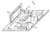
- FIG. 1is a perspective view of a combined RFID and optical imager according to the present invention.
- FIG. 2is a schematic of a combined RFID and optical imager according to the present invention.
- FIG. 3is a flowchart of main-line processing according to the present invention.
- FIG. 4A and FIG. 4Bare a flowchart of trigger command processing according to the present invention.
- Module 10generally comprises a microcontroller 12 that interconnects a first submodule, such as an optical imager 14 , and a second submodule, such as a RFID unit 16 , to a single host interface 18 .
- module 10is capable of interconnecting any variety of data capturing devices as submodules and providing host controllability, including optical imagers, RFID transceivers, lasers, scales, thermometers or temperature probes, etc., in any variety of combinations.
- Module 10may be arranged on a single printed circuit board 22 and encased as a single unit or housing. Integration of imager 14 and RFID unit 16 through interface 18 allows for combining control of operation of both submodules, such as RFID reading and barcode, through module 10 , as will be explained in detail hereinafter.
- a first submodule of module 10is illustrated as an optical imager 14 comprising an image engine 20 having image processing circuitry interconnected to microcontroller 12 for omni-directional optical scanning.
- Image engine 20controls an image sensor 24 , such as a complementary metal oxide semiconductor (CMOS) image sensor, and is capable of capturing two-dimensional images of 1D linear barcodes, 2D stacked/matrix barcodes, standard optical character recognition (OCR) fonts, Reduced Space Symbology (RSS) barcodes, and postal barcodes, as well as providing image captured images for use in a wide range of applications, such as image and shape recognition, signature capture, image capture, and non-standard optical character recognition.
- CMOScomplementary metal oxide semiconductor
- Imager 14may further include an integrated illumination source 26 connected to engine 20 , such as one or more light emitting diodes (LEDs) of various wavelengths, to enhance illumination, operation, and image capture.
- module 10may include red LEDs for general illumination and green LEDs for targeting.
- Imager 14may comprise, but is not limited to, an IT4X10/80 SR/SF or IT5X10/80 series imager available from Hand Held Products, Inc. of Skaneateles Falls, N.Y. that is capable of scanning and decoding most standard barcodes including linear, stacked linear, matrix, OCR, and postal codes.
- the IT5X10/80 series imageris a CMOS-based decoded output engines that can read 2D codes, and has image capture capabilities sufficient for use with module 10 .
- Imager 14obtains an optical image of the field of view and, using preprogrammed algorithms in image engine 20 , deciphers the context of the image to determine the presence of any decodable barcodes, linear codes, matrix codes, and the like.
- Image engine 20may be programmed to perform other image processing algorithms on the image captured by imager 14 , such as shape recognition, match filtering, statistical analysis (e.g., threshold detection), and other high-level processing techniques.
- a captured imagemay be processed by microprocessor 12 , albeit with a decreased level of performance due to the additional communication time needed to transfer images from image engine 20 to microprocessor 12 .
- Second submodule of module 10may comprise an RFID unit 16 including a RFID transceiver 30 and associated RFID antenna 32 supporting standard RFID protocols, such as the TI Tag-it transponder protocol or ISO 15693.
- transceiver 30operates at 13.56 MHz, and may comprise a S6700 Multi-Protocol Transceiver IC available from Texas Instruments of Dallas, Tex.
- RFID unit 16may further include a speaker or LED (not shown) for audibly indicating a successful interrogation of a RFID tag.
- Antenna 32is preferably a loop antenna of various sizes and turns implemented on a printed circuit board and connected to module 10 , or a wire loop installed antenna installed directly onto module 10 .
- Antenna 32may be positioned remotely, thereby reducing the footprint of module 10 using an external connector, such as a MMCX coaxial connector.
- RFID transceiver 30may be programmed to interrogate passive or active tags, process signals received from such tags (e.g., analog to digital conversion), and provide the information from the tags to microcontroller 12 for further processing or transmittal to a host computer via interface 18 .
- Host interface 18comprises a host transceiver 34 and a host connector 36 for interconnection to a host device 38 .
- Interface 18may comprise a conventional RS232 transceiver and associated 12 pin RJ style jack.
- an ADM202EARNavailable from Analog Devices, Inc. of Norwood, Mass. is a suitable RS-232/V.28 interface device having compliant levels of electromagnetic emissions and immunity.
- interface 18may comprise other conventional buses, such as USB, IEEE 1394, I2C, SPI, or PCMCIA, or other connector styles, such as an FFC style to an embedded host or another module 10 .
- Interface 18may also comprise a wireless transceiver in lieu of connector 36 for wireless communication to a host computer.
- SS-641010S-A-NFmay serve as connector 36 for mating with a Stewart Connector 937-SP-361010-031 matching connector of a host device.
- Host interface 18may also comprise a Molex MX52588 connector.
- host transceiver 34is programmed with the applicable protocols for interfacing with a host computer, such as USB, Bluetooth(r), and IrDA protocols.
- Transceiver 34may also be programmed to support both non-inverted signal sense and inverted signal sense.
- Microcontroller 12comprises a conventional programmable microprocessor having on-chip peripherals, such as central processing unit, Flash EEPROM, RAM, asynchronous serial communications interface modules, serial peripheral interfaces, Inter-IC Buses, timer modules, pulse modulators with fault protection modules, pulse width modulators, analog-to-digital converters, and digital-to-analog converters. Additionally, the inclusion of a PLL circuit allows power consumption and performance to be adjusted to suit operational requirements. In addition to the I/O ports dedicated I/O port bits may be provided. Microcontroller 12 may further include an on-chip bandgap based voltage regulator that generates an internal digital supply voltage from an external supply range. Microcontroller 12 preferably comprises a Motorola MC9S12E128.
- microcontroller 12which receives and interprets host commands, and then executes the appropriate functions by driving imager 14 and/or RFID unit 16 accordingly.
- the operation of imager 14 and RFID unit 16may be triggered by serial commands sent to module 10 from a host device 38 , or by a hardware button communicating directly with connector 36 or through host device 38 .
- Microcontroller 12may further be programmed to execute the functions otherwise performed by one or more of image engine 20 , RFID transceiver 30 , and host transceiver 34 , thereby reducing the amount of circuitry and hardware required by module 10 .
- module 10When integrating imager 14 and RFID unit 16 , module 10 has three principle operational modes: image scanning using imager 14 , tag interrogation using RFID unit 16 , an interleaved mode that is a combination thereof, and a simultaneous mode.
- imaging-only modemodule 10 will capture images and perform the applicable algorithms, such as barcode deciphering, until a barcode is detected or the device is un-triggered.
- RFID-onlymodule 10 will interrogate until a tag is successfully read or module 10 is un-triggered.
- interleaved modemodule 10 toggles between imaging and interrogation according to a predetermined timeout schedule.
- simultaneous modemodule 10 causes simultaneous imaging and interrogation.
- module 10may be programmed with timeouts to prevent hang-ups. As module 10 can receive, interpret, and execute host commands, these modes may be controlled by a user from host device 38 .
- Microcontroller 12may direct RFID interrogation using RFID unit 16 in at least two modes.
- RFID unit 16may operate in a free form mode that reads and writes data as a continuous stream, which is limited only by memory capacity. Once RFID unit 16 is triggered, depending on the mode, data is transmitted from the serial port. Second, RFID unit 16 may operate in block mode, where a user may access individual blocks of information via commands sent through interface 18 and interpreted by microcontroller 12 .
- External control of module 10is accomplished by a predefined protocol and set of serial host commands that are sent to module 10 from host device 38 .
- the host commandsare received by microcontroller 12 , which executes the appropriate steps based on the content of the host command.
- microcontroller 12may be programmed to recognize host commands that trigger the activation of imager 14 and/or RFID unit 16 .
- Host commandsmay also be defined to whether the data obtained from imager 14 and/or RFID unit 16 is stored locally in module 10 or passed through interface 18 to host device 38 .
- Host commandsmay also be provided that enable the various scanning or imaging modes available from imager 14 and RFID unit 16 , control the amount of time that imager 14 and RFID unit 16 will attempt scanning before timing out, direct the reading and writing of image and scan data, and select the location where the data is to be written.
- imager 14 and RFID unit 16commands for opening and closing connections to image engine 20 and RFID transceiver 30 , as well as commands that return the status of the connection are useful.
- a host command received from host device 38may trigger the capture of barcode or RFID data from imager 14 or RFID unit 16 .
- a timeoutoccurs or triggering is turned off via a second host command, and the appropriate feedback is provided to host device 38 .
- the host commandsmay be preprogrammed into microprocessor 12 and separately provided to host device 38 as a software package for controlling module 10 .
- software for editing host commandsmay be supplied to host device 38 to allow a user to edit, add, or delete commands and the corresponding functionality.
- FIG. 3illustrates an embodiment of main-line host command processing in microprocessor 12 according to the present invention.
- the specific nomenclature used to define the various routinesmay be varied by the user or software developer provided that the appropriate functions are performed, and any number of routines and subroutines may be defined and executed in various orders to accomplish image and RFID reading and processing according to the present invention.
- microcontroller 12runs a routine, referred to as GetHostCommand 42 , to check whether a host command has been received from host device 38 .
- microprocessor 12Upon receipt of a host command, microprocessor 12 checks whether the command is an RFID control command, CMD_RFID 44 . If so, the command is processed by routine ProcessRFID_Command 46 .
- CMD_TRIGGER 48If not, a check is performed to see whether the command is a trigger command, CMD_TRIGGER 48 . If the command is a trigger command, the appropriate instruction are processed to initiate triggering, InitTriggerProcessing 50 and a variable, referred to as CurrentlyTriggered 52 , is assigned the value of TRUE or FALSE depending on whether the selected device has already been triggered. If the command is not a trigger command, a check is performed to see whether the command is an untrigger command, CMD_UNTRIGGER 54 .
- UnTriggerImager 56If the command is an untrigger command, the appropriate steps are taken to stop triggering, UnTriggerImager 56 , and a variable, CurrentlyTriggered 58 , is assigned the value of TRUE or FALSE depending on whether the selected device has already been triggered.
- microprocessor 12checks to see whether a hardware trigger has been pressed 60 , the triggering processing is performed, InitTriggerProcessing 62 , and a variable, referred to as CurrentlyTriggered 64 , is assigned the value of TRUE or FALSE depending on whether the selected device has already been triggered. If a hardware trigger has not been pressed 60 , the appropriate instruction are processed to stop triggering, UnTriggerImager 66 , and a variable, referred to as CurrentlyTriggered 68 , is assigned the value of TRUE or FALSE depending on whether the selected device has already been triggered.
- microprocessorchecks to see whether the CurrentlyTriggered variable is TRUE or FALSE 70 , and then calls function Trigger 72 or function UnTrigger 74 as appropriate. Data is then read from imager 14 and written to the host, ImagerReadAllHostWrite 76 , and host data that should be routed to imager 14 is written to it, FifoGetAllDataImagerWrite 78 .
- microcontroller 12Upon receipt of a trigger command, microcontroller 12 first checks to see whether barcode only scanning 80 , RFID only scanning 82 , interleaved RFID and barcode scanning 84 , or simultaneous RFID and image scanning 86 has been previously selected. If bar code only scanning 80 has been selected for the first time 88 , and since InitTriggerProcessing 50 has been called, microcontroller 12 triggers imaging 90 . If an image is successfully captured and applicable information successfully extracted from the image 92 , such as barcode, microcontroller 12 assigns FALSE to the variable CurrentlyTriggered 94 .
- microcontroller 12turns the RFID transmitter on 94 . If an RFID tag is successfully read 96 , an audible tone is sounded and microcontroller 12 sets variable CurrentlyTriggered to FALSE 98 . Microcontroller 12 turns transmitter off 100 . If interleaved RFID and barcode scanning 84 has been selected, microcontroller 12 toggles operation of imager 14 and RFID unit 16 using a timer 102 . If simultaneous RFID and image scanning 86 has been selected, microcontroller 12 checks to see whether the triggering is for the first time 104 and, if so, triggers the imager 106 . Transmission from the RFID unit 16 is also turned on 108 , and a nearby RFID tag is read 110 .
- variable CurrentlyTriggeredis set to FALSE 112 .
- Imager 14is also untriggered 114 and the transmitter is turned off 116 . If the image is successfully processed, e.g., a barcode is received 118 , and variable CurrentlyTriggered is set to FALSE 120 .
Landscapes
- Health & Medical Sciences (AREA)
- Life Sciences & Earth Sciences (AREA)
- Surgery (AREA)
- Engineering & Computer Science (AREA)
- General Health & Medical Sciences (AREA)
- Public Health (AREA)
- Heart & Thoracic Surgery (AREA)
- Biomedical Technology (AREA)
- Medical Informatics (AREA)
- Animal Behavior & Ethology (AREA)
- Veterinary Medicine (AREA)
- Molecular Biology (AREA)
- Nuclear Medicine, Radiotherapy & Molecular Imaging (AREA)
- Oral & Maxillofacial Surgery (AREA)
- Pathology (AREA)
- Hematology (AREA)
- Anesthesiology (AREA)
- Vascular Medicine (AREA)
- Chemical & Material Sciences (AREA)
- Bioinformatics & Cheminformatics (AREA)
- Medicinal Chemistry (AREA)
- Epidemiology (AREA)
- Primary Health Care (AREA)
- Physics & Mathematics (AREA)
- Electromagnetism (AREA)
- Image Input (AREA)
Abstract
Description
Claims (19)
Priority Applications (3)
| Application Number | Priority Date | Filing Date | Title |
|---|---|---|---|
| US11/308,170US7766235B2 (en) | 2006-03-09 | 2006-03-09 | Combined radio frequency identification and optical imaging module |
| US11/279,275US7743975B2 (en) | 2006-03-09 | 2006-04-11 | Infusion pump having radiofrequency identification and optical imaging capabilities |
| US11/420,350US7614554B2 (en) | 2006-03-09 | 2006-05-25 | Electrosurgical device having RFID and optical imaging capabilities |
Applications Claiming Priority (1)
| Application Number | Priority Date | Filing Date | Title |
|---|---|---|---|
| US11/308,170US7766235B2 (en) | 2006-03-09 | 2006-03-09 | Combined radio frequency identification and optical imaging module |
Related Child Applications (2)
| Application Number | Title | Priority Date | Filing Date |
|---|---|---|---|
| US11/279,275Continuation-In-PartUS7743975B2 (en) | 2006-03-09 | 2006-04-11 | Infusion pump having radiofrequency identification and optical imaging capabilities |
| US11/420,350Continuation-In-PartUS7614554B2 (en) | 2006-03-09 | 2006-05-25 | Electrosurgical device having RFID and optical imaging capabilities |
Publications (2)
| Publication Number | Publication Date |
|---|---|
| US20070210158A1 US20070210158A1 (en) | 2007-09-13 |
| US7766235B2true US7766235B2 (en) | 2010-08-03 |
Family
ID=38477939
Family Applications (1)
| Application Number | Title | Priority Date | Filing Date |
|---|---|---|---|
| US11/308,170Active2026-10-10US7766235B2 (en) | 2006-03-09 | 2006-03-09 | Combined radio frequency identification and optical imaging module |
Country Status (1)
| Country | Link |
|---|---|
| US (1) | US7766235B2 (en) |
Cited By (5)
| Publication number | Priority date | Publication date | Assignee | Title |
|---|---|---|---|---|
| US20090045261A1 (en)* | 2007-08-14 | 2009-02-19 | Jadak, Llc | Method For Providing User Feedback In An Autoidentification System |
| US9489785B2 (en) | 2013-03-14 | 2016-11-08 | Covidien Lp | RFID secure authentication |
| US10130382B2 (en) | 2014-03-27 | 2018-11-20 | Medtronic Xomed, Inc. | Powered surgical handpiece having a surgical tool with an RFID tag |
| US11526380B2 (en) | 2019-12-19 | 2022-12-13 | Google Llc | Resource management unit for capturing operating system configuration states and offloading tasks |
| US11630698B2 (en) | 2019-12-19 | 2023-04-18 | Google Llc | Resource management unit for capturing operating system configuration states and swapping memory content |
Families Citing this family (2)
| Publication number | Priority date | Publication date | Assignee | Title |
|---|---|---|---|---|
| US9251455B2 (en) | 2013-08-22 | 2016-02-02 | Verily Life Sciences Llc | Using unique identifiers to retrieve configuration data for tag devices |
| CN112309532B (en)* | 2020-09-28 | 2023-09-26 | 北京京东拓先科技有限公司 | Information feedback method and device |
Citations (20)
| Publication number | Priority date | Publication date | Assignee | Title |
|---|---|---|---|---|
| US6127928A (en)* | 1998-02-10 | 2000-10-03 | E-Tag Systems, Inc. | Method and apparatus for locating and tracking documents and other objects |
| US20020063622A1 (en)* | 2000-11-29 | 2002-05-30 | Ludwig Kipp | Method and system for communicating with and tracking RFID transponders |
| US6501382B1 (en) | 2001-06-11 | 2002-12-31 | Timken Company | Bearing with data storage device |
| US20030095525A1 (en) | 2000-04-13 | 2003-05-22 | Daniel Lavin | Navigation control unit for a wireless computer resource access device, such as a wireless web content access device |
| US20030132298A1 (en) | 1996-09-05 | 2003-07-17 | Jerome Swartz | Consumer interactive shopping system |
| US20040118920A1 (en) | 2002-12-18 | 2004-06-24 | Duanfeng He | System and method for verifying optical character recognition of optical code reads |
| US20040177032A1 (en) | 2003-03-03 | 2004-09-09 | Bradley A. (Tony) W. | System, method, and apparatus for identifying and authenticating the presence of high value assets at remote locations |
| US20050120260A1 (en)* | 2003-11-19 | 2005-06-02 | Fuji Xerox Co., Ltd | Image forming apparatus and control method of an image forming apparatus |
| US20050144044A1 (en) | 2003-09-29 | 2005-06-30 | Samsung Electronics Co., Ltd. | System and apparatus for efficiently utilizing network capacity in a healthcare setting |
| US20050150959A1 (en) | 2004-01-09 | 2005-07-14 | John Izzo | Optical reader |
| US20050156040A1 (en) | 2004-01-16 | 2005-07-21 | Young David H. | Radio frequency identification device with movable antenna |
| US20050184160A1 (en) | 2004-02-20 | 2005-08-25 | Jay Steinmetz | Combination handheld sealer/wireless scanning/imaging device |
| US20050203941A1 (en) | 2004-01-14 | 2005-09-15 | Polarine Christine D.A. | Monitoring device used for producing compositions |
| US20050282603A1 (en) | 2004-06-18 | 2005-12-22 | Igt | Gaming machine user interface |
| US20060023930A1 (en) | 2004-07-29 | 2006-02-02 | Mehul Patel | Device for digitizing and processing checks in accordance with the Check 21 Act and for reading and decoding optical codes |
| US20060109119A1 (en)* | 2004-11-19 | 2006-05-25 | Jeremy Burr | RFID tag in a printed circuit board |
| US20060113374A1 (en)* | 2004-11-30 | 2006-06-01 | Taylor Peter S | System and method of RFID data tracking in winemaking process |
| US20080180215A1 (en)* | 2007-01-25 | 2008-07-31 | Jadak Technologies, Inc. | Antenna for Combined RFID Optical Imager |
| US20090266898A1 (en)* | 2004-03-17 | 2009-10-29 | Timothy Miller | Accuracy-Enhanced Scanner |
| US20090289116A1 (en)* | 2008-05-21 | 2009-11-26 | Sensormatic Electronics Corporation | Handheld combination bar code and rfid reader with integrated electronics and antenna |
- 2006
- 2006-03-09USUS11/308,170patent/US7766235B2/enactiveActive
Patent Citations (21)
| Publication number | Priority date | Publication date | Assignee | Title |
|---|---|---|---|---|
| US20030132298A1 (en) | 1996-09-05 | 2003-07-17 | Jerome Swartz | Consumer interactive shopping system |
| US6127928A (en)* | 1998-02-10 | 2000-10-03 | E-Tag Systems, Inc. | Method and apparatus for locating and tracking documents and other objects |
| US20030095525A1 (en) | 2000-04-13 | 2003-05-22 | Daniel Lavin | Navigation control unit for a wireless computer resource access device, such as a wireless web content access device |
| US20020063622A1 (en)* | 2000-11-29 | 2002-05-30 | Ludwig Kipp | Method and system for communicating with and tracking RFID transponders |
| US6501382B1 (en) | 2001-06-11 | 2002-12-31 | Timken Company | Bearing with data storage device |
| US20040118920A1 (en) | 2002-12-18 | 2004-06-24 | Duanfeng He | System and method for verifying optical character recognition of optical code reads |
| WO2004059563A1 (en) | 2002-12-18 | 2004-07-15 | Symbol Technologies, Inc. | System and method for verifying optical code reads and rfid reads |
| US20040177032A1 (en) | 2003-03-03 | 2004-09-09 | Bradley A. (Tony) W. | System, method, and apparatus for identifying and authenticating the presence of high value assets at remote locations |
| US20050144044A1 (en) | 2003-09-29 | 2005-06-30 | Samsung Electronics Co., Ltd. | System and apparatus for efficiently utilizing network capacity in a healthcare setting |
| US20050120260A1 (en)* | 2003-11-19 | 2005-06-02 | Fuji Xerox Co., Ltd | Image forming apparatus and control method of an image forming apparatus |
| US20050150959A1 (en) | 2004-01-09 | 2005-07-14 | John Izzo | Optical reader |
| US20050203941A1 (en) | 2004-01-14 | 2005-09-15 | Polarine Christine D.A. | Monitoring device used for producing compositions |
| US20050156040A1 (en) | 2004-01-16 | 2005-07-21 | Young David H. | Radio frequency identification device with movable antenna |
| US20050184160A1 (en) | 2004-02-20 | 2005-08-25 | Jay Steinmetz | Combination handheld sealer/wireless scanning/imaging device |
| US20090266898A1 (en)* | 2004-03-17 | 2009-10-29 | Timothy Miller | Accuracy-Enhanced Scanner |
| US20050282603A1 (en) | 2004-06-18 | 2005-12-22 | Igt | Gaming machine user interface |
| US20060023930A1 (en) | 2004-07-29 | 2006-02-02 | Mehul Patel | Device for digitizing and processing checks in accordance with the Check 21 Act and for reading and decoding optical codes |
| US20060109119A1 (en)* | 2004-11-19 | 2006-05-25 | Jeremy Burr | RFID tag in a printed circuit board |
| US20060113374A1 (en)* | 2004-11-30 | 2006-06-01 | Taylor Peter S | System and method of RFID data tracking in winemaking process |
| US20080180215A1 (en)* | 2007-01-25 | 2008-07-31 | Jadak Technologies, Inc. | Antenna for Combined RFID Optical Imager |
| US20090289116A1 (en)* | 2008-05-21 | 2009-11-26 | Sensormatic Electronics Corporation | Handheld combination bar code and rfid reader with integrated electronics and antenna |
Cited By (10)
| Publication number | Priority date | Publication date | Assignee | Title |
|---|---|---|---|---|
| US20090045261A1 (en)* | 2007-08-14 | 2009-02-19 | Jadak, Llc | Method For Providing User Feedback In An Autoidentification System |
| US7942329B2 (en)* | 2007-08-14 | 2011-05-17 | Jadak, Llc | Method for providing user feedback in an autoidentification system |
| US9489785B2 (en) | 2013-03-14 | 2016-11-08 | Covidien Lp | RFID secure authentication |
| US9774455B2 (en) | 2013-03-14 | 2017-09-26 | Covidien Lp | RFID secure authentication |
| US10298403B2 (en) | 2013-03-14 | 2019-05-21 | Covidien Lp | RFID secure authentication |
| US10130382B2 (en) | 2014-03-27 | 2018-11-20 | Medtronic Xomed, Inc. | Powered surgical handpiece having a surgical tool with an RFID tag |
| US10987121B2 (en) | 2014-03-27 | 2021-04-27 | Medtronic Xomed, Inc. | Powered surgical handpiece having a surgical tool with an RFID tag |
| US11526380B2 (en) | 2019-12-19 | 2022-12-13 | Google Llc | Resource management unit for capturing operating system configuration states and offloading tasks |
| US11630698B2 (en) | 2019-12-19 | 2023-04-18 | Google Llc | Resource management unit for capturing operating system configuration states and swapping memory content |
| US11782761B2 (en) | 2019-12-19 | 2023-10-10 | Google Llc | Resource management unit for capturing operating system configuration states and offloading tasks |
Also Published As
| Publication number | Publication date |
|---|---|
| US20070210158A1 (en) | 2007-09-13 |
Similar Documents
| Publication | Publication Date | Title |
|---|---|---|
| US7631809B2 (en) | Antenna for combined RFID optical imager | |
| US7942329B2 (en) | Method for providing user feedback in an autoidentification system | |
| US7614554B2 (en) | Electrosurgical device having RFID and optical imaging capabilities | |
| US8162219B2 (en) | System and method for logo identification and verification | |
| US7766235B2 (en) | Combined radio frequency identification and optical imaging module | |
| US7743975B2 (en) | Infusion pump having radiofrequency identification and optical imaging capabilities | |
| EP1708118A2 (en) | Combination RFID/image reader | |
| US9165174B2 (en) | Indicia reader | |
| US8896423B2 (en) | Physiological sensor system with automatic authentication and validation by means of a Radio Frequency Identification protocol with an integrated RFID interrogator system | |
| AU2003297246B2 (en) | System and method for verifying optical code reads and RFID reads | |
| EP2502181B1 (en) | Method and apparatus for augmenting optical barcode scanner with rfid | |
| US20160110577A1 (en) | Apparatus operative for capture of image data | |
| EP3370397A1 (en) | Universal connectivity for non-universal devices | |
| US20130222559A1 (en) | Id scanner with machine-readable coded indicia reader and card imaging digital camera | |
| WO2002093458A2 (en) | Optical reader having a plurality of imaging modes | |
| EP2495685A2 (en) | Imager reader with hand gesture interface | |
| WO2010138013A4 (en) | Handheld portable device for verification of travel and personal documents, reading of biometric data and identification of persons holding these documents | |
| US8622304B2 (en) | Imaging reader and method with combined image data and system data | |
| US9529742B2 (en) | Method of programming the default interface software in an indicia reading device | |
| EP1755065B2 (en) | System and method for verifying optical code reads and RFID reads | |
| EP2211290B1 (en) | Imaging reader for and method of receipt acknowledgement and symbol capture | |
| US7764163B2 (en) | Modular radio frequency identification unit | |
| US20090212114A1 (en) | Optical Imaging Alignment System and Method | |
| EP3605551B1 (en) | System with a smart filtration and/or diffusion device |
Legal Events
| Date | Code | Title | Description |
|---|---|---|---|
| AS | Assignment | Owner name:JADAK TECHNOLOGIES, INC., NEW YORK Free format text:ASSIGNMENT OF ASSIGNORS INTEREST;ASSIGNOR:MILLER, DAVID PAUL;REEL/FRAME:017287/0823 Effective date:20060309 | |
| AS | Assignment | Owner name:JADAK, LLC,NEW YORK Free format text:ASSIGNMENT OF ASSIGNORS INTEREST;ASSIGNOR:JADAK TECHNOLOGIES, INC.;REEL/FRAME:019030/0897 Effective date:20070319 Owner name:JADAK, LLC, NEW YORK Free format text:ASSIGNMENT OF ASSIGNORS INTEREST;ASSIGNOR:JADAK TECHNOLOGIES, INC.;REEL/FRAME:019030/0897 Effective date:20070319 | |
| STCF | Information on status: patent grant | Free format text:PATENTED CASE | |
| FPAY | Fee payment | Year of fee payment:4 | |
| AS | Assignment | Owner name:BANK OF AMERICA, N.A., ILLINOIS Free format text:SECURITY INTEREST;ASSIGNOR:JADAK, LLC;REEL/FRAME:032626/0987 Effective date:20140404 | |
| AS | Assignment | Owner name:NOVANTA CORPORATION, MASSACHUSETTS Free format text:ASSIGNMENT OF ASSIGNORS INTEREST;ASSIGNOR:JADAK, LLC;REEL/FRAME:044588/0785 Effective date:20171229 | |
| MAFP | Maintenance fee payment | Free format text:PAYMENT OF MAINTENANCE FEE, 8TH YR, SMALL ENTITY (ORIGINAL EVENT CODE: M2552) Year of fee payment:8 | |
| MAFP | Maintenance fee payment | Free format text:PAYMENT OF MAINTENANCE FEE, 12TH YR, SMALL ENTITY (ORIGINAL EVENT CODE: M2553); ENTITY STATUS OF PATENT OWNER: SMALL ENTITY Year of fee payment:12 |