US7766135B2 - Front bicycle suspension assembly with inertia valve - Google Patents
Front bicycle suspension assembly with inertia valveDownload PDFInfo
- Publication number
- US7766135B2 US7766135B2US11/750,901US75090107AUS7766135B2US 7766135 B2US7766135 B2US 7766135B2US 75090107 AUS75090107 AUS 75090107AUS 7766135 B2US7766135 B2US 7766135B2
- Authority
- US
- United States
- Prior art keywords
- inertia mass
- inertia
- valve
- fluid
- bicycle
- Prior art date
- Legal status (The legal status is an assumption and is not a legal conclusion. Google has not performed a legal analysis and makes no representation as to the accuracy of the status listed.)
- Expired - Fee Related, expires
Links
Images


Classifications
- F—MECHANICAL ENGINEERING; LIGHTING; HEATING; WEAPONS; BLASTING
- F16—ENGINEERING ELEMENTS AND UNITS; GENERAL MEASURES FOR PRODUCING AND MAINTAINING EFFECTIVE FUNCTIONING OF MACHINES OR INSTALLATIONS; THERMAL INSULATION IN GENERAL
- F16F—SPRINGS; SHOCK-ABSORBERS; MEANS FOR DAMPING VIBRATION
- F16F9/00—Springs, vibration-dampers, shock-absorbers, or similarly-constructed movement-dampers using a fluid or the equivalent as damping medium
- F16F9/32—Details
- F16F9/50—Special means providing automatic damping adjustment, i.e. self-adjustment of damping by particular sliding movements of a valve element, other than flexions or displacement of valve discs; Special means providing self-adjustment of spring characteristics
- F16F9/504—Inertia, i.e. acceleration,-sensitive means
- B—PERFORMING OPERATIONS; TRANSPORTING
- B62—LAND VEHICLES FOR TRAVELLING OTHERWISE THAN ON RAILS
- B62K—CYCLES; CYCLE FRAMES; CYCLE STEERING DEVICES; RIDER-OPERATED TERMINAL CONTROLS SPECIALLY ADAPTED FOR CYCLES; CYCLE AXLE SUSPENSIONS; CYCLE SIDE-CARS, FORECARS, OR THE LIKE
- B62K25/00—Axle suspensions
- B62K25/04—Axle suspensions for mounting axles resiliently on cycle frame or fork
- B62K25/06—Axle suspensions for mounting axles resiliently on cycle frame or fork with telescopic fork, e.g. including auxiliary rocking arms
- B62K25/08—Axle suspensions for mounting axles resiliently on cycle frame or fork with telescopic fork, e.g. including auxiliary rocking arms for front wheel
- B—PERFORMING OPERATIONS; TRANSPORTING
- B62—LAND VEHICLES FOR TRAVELLING OTHERWISE THAN ON RAILS
- B62K—CYCLES; CYCLE FRAMES; CYCLE STEERING DEVICES; RIDER-OPERATED TERMINAL CONTROLS SPECIALLY ADAPTED FOR CYCLES; CYCLE AXLE SUSPENSIONS; CYCLE SIDE-CARS, FORECARS, OR THE LIKE
- B62K25/00—Axle suspensions
- B62K25/04—Axle suspensions for mounting axles resiliently on cycle frame or fork
- B62K25/28—Axle suspensions for mounting axles resiliently on cycle frame or fork with pivoted chain-stay
- B62K25/286—Axle suspensions for mounting axles resiliently on cycle frame or fork with pivoted chain-stay the shock absorber being connected to the chain-stay via a linkage mechanism
- F—MECHANICAL ENGINEERING; LIGHTING; HEATING; WEAPONS; BLASTING
- F16—ENGINEERING ELEMENTS AND UNITS; GENERAL MEASURES FOR PRODUCING AND MAINTAINING EFFECTIVE FUNCTIONING OF MACHINES OR INSTALLATIONS; THERMAL INSULATION IN GENERAL
- F16F—SPRINGS; SHOCK-ABSORBERS; MEANS FOR DAMPING VIBRATION
- F16F9/00—Springs, vibration-dampers, shock-absorbers, or similarly-constructed movement-dampers using a fluid or the equivalent as damping medium
- F16F9/06—Springs, vibration-dampers, shock-absorbers, or similarly-constructed movement-dampers using a fluid or the equivalent as damping medium using both gas and liquid
- F16F9/064—Units characterised by the location or shape of the expansion chamber
- F—MECHANICAL ENGINEERING; LIGHTING; HEATING; WEAPONS; BLASTING
- F16—ENGINEERING ELEMENTS AND UNITS; GENERAL MEASURES FOR PRODUCING AND MAINTAINING EFFECTIVE FUNCTIONING OF MACHINES OR INSTALLATIONS; THERMAL INSULATION IN GENERAL
- F16F—SPRINGS; SHOCK-ABSORBERS; MEANS FOR DAMPING VIBRATION
- F16F9/00—Springs, vibration-dampers, shock-absorbers, or similarly-constructed movement-dampers using a fluid or the equivalent as damping medium
- F16F9/32—Details
- F16F9/34—Special valve constructions; Shape or construction of throttling passages
- B—PERFORMING OPERATIONS; TRANSPORTING
- B62—LAND VEHICLES FOR TRAVELLING OTHERWISE THAN ON RAILS
- B62K—CYCLES; CYCLE FRAMES; CYCLE STEERING DEVICES; RIDER-OPERATED TERMINAL CONTROLS SPECIALLY ADAPTED FOR CYCLES; CYCLE AXLE SUSPENSIONS; CYCLE SIDE-CARS, FORECARS, OR THE LIKE
- B62K25/00—Axle suspensions
- B62K25/04—Axle suspensions for mounting axles resiliently on cycle frame or fork
- B62K2025/048—Axle suspensions for mounting axles resiliently on cycle frame or fork with suspension manual adjustment details
- Y—GENERAL TAGGING OF NEW TECHNOLOGICAL DEVELOPMENTS; GENERAL TAGGING OF CROSS-SECTIONAL TECHNOLOGIES SPANNING OVER SEVERAL SECTIONS OF THE IPC; TECHNICAL SUBJECTS COVERED BY FORMER USPC CROSS-REFERENCE ART COLLECTIONS [XRACs] AND DIGESTS
- Y10—TECHNICAL SUBJECTS COVERED BY FORMER USPC
- Y10T—TECHNICAL SUBJECTS COVERED BY FORMER US CLASSIFICATION
- Y10T29/00—Metal working
- Y10T29/49—Method of mechanical manufacture
- Y10T29/494—Fluidic or fluid actuated device making
Definitions
- the present inventionrelates to vehicle suspensions systems. More particularly, the present invention relates to acceleration sensitive damping arrangements suitable for use in vehicle dampers (e.g., shock absorbers, struts, front forks).
- vehicle damperse.g., shock absorbers, struts, front forks.
- Inertia valvesare utilized in vehicle shock absorbers in an attempt to sense instantaneous accelerations originating from a particular portion of the vehicle, or acting in a particular direction, and to alter the rate of damping accordingly.
- the inertia valvemay be configured to sense vertical accelerations originating at the sprung mass (e.g., the body of the vehicle) or at the unsprung mass (e.g., a wheel and associated linkage of the vehicle).
- the inertia valvemay be configured to sense lateral accelerations of the vehicle.
- inertia valve shock absorbersDespite the apparent potential, and a long history of numerous attempts to utilize inertia valves in vehicle suspension, commercial inertia valve shock absorbers have enjoyed only limited success. Most attempted inertia valve shock absorbers have suffered from unresponsive or inconsistent operation due to undesired extraneous forces acting on the inertia valve. These extraneous forces may result from manufacturing limitations and/or external sources and often inhibit, or even prevent, operation of the inertia valve.
- inertia valve shock absorbersfor off-road bicycle, or mountain bike, applications.
- the problems associated with the use of inertia valves, mentioned above in relation to other vehicles,are magnified in the environment of lightweight vehicles and the relatively small size of mountain bike shock absorbers. Therefore, a need exists for an inertia valve shock absorber that can be commercially produced, and provides responsive, consistent performance without the problems associated with prior inertia valve designs.
- a preferred embodimentis a shock absorber comprising a first fluid chamber, a second fluid chamber and a fluid circuit connecting the first fluid chamber and the second fluid chamber.
- An inertia valveincludes an inertia mass movable between a first position and a second position. The inertia valve permits a first rate of fluid flow through the fluid circuit in the first position permits a second rate of fluid flow through the fluid circuit in the second position of the inertia mass. The second rate of fluid flow is non-equal to the first rate.
- a leading surface of the inertia mass when moving in a direction from the first position to the second positiondefines a leading surface area. A ratio of a mass of the inertia mass to the leading surface area is greater than about 130 grams per square inch.
- a preferred embodimentis a shock absorber including a first fluid chamber, a second fluid chamber and a fluid circuit connecting the first fluid chamber and the second fluid chamber.
- An inertia valveincludes an inertia mass movable between a first position and a second position. The inertia valve permits a first rate of fluid flow through the fluid circuit in the first position and permits a second rate of fluid flow in the second position. The second rate of fluid flow is non-equal to the first rate.
- a ratio of a mass of the inertia mass to a volume of the inertia massis greater than about 148 grams per cubic inch.
- a preferred embodimentis a shock absorber including a first fluid chamber, a second fluid chamber, and a fluid circuit connecting the first fluid chamber and the second fluid chamber.
- An inertia valveincludes an inertia mass movable between a first position and a second position. The inertia valve permits a first rate of fluid flow through the fluid circuit in the first position of the inertia mass and a second rate of fluid flow in the second position of the inertia mass. The second rate of fluid flow is non-equal to the first rate. At least a portion of the inertia mass comprises tungsten.
- a preferred embodimentis a shock absorber including a first fluid chamber, a second fluid chamber, and a fluid circuit connecting the first fluid chamber and the second fluid chamber.
- An inertia valveincludes an inertia mass movable between a first position and a second position. The inertia valve permits a first rate of fluid flow through the fluid circuit in the first position of the inertia mass and a second rate of fluid flow through the fluid circuit in the second position. The second rate of fluid flow is non-equal to the first rate.
- the inertia masscomprises a first portion and a second portion. The first portion is constructed from a first material having a first density and the second portion being constructed from a second material having a second density, the second density being greater than the first density.
- a preferred embodimentis a shock absorber including a first fluid chamber, a second fluid chamber, and a fluid circuit connecting the first fluid chamber and the second fluid chamber.
- An inertia valveincludes an inertia mass moveable between a first position and a second position. The inertia valve permits a first rate of fluid flow through the fluid circuit in the first position of the inertia mass and a second rate of fluid flow in the second position. The second rate of fluid flow is non-equal to the first rate.
- the inertia massincludes a collapsible section defining at least a portion of an external surface of the inertia mass.
- the collapsible sectionhas a first orientation when the inertia mass is moving in a first direction from the first position to the second position and a second orientation when the inertia mass is moving in a second direction from the second position to the first position.
- the inertia masshas a first flow resistance when the collapsible section is in the first orientation and a second flow resistance when the collapsible section is in the second orientation. The second flow resistance is greater than the first flow resistance.
- a preferred embodimentis a shock absorber including a first fluid chamber, a second fluid chamber, and a fluid circuit connecting the first fluid chamber and the second fluid chamber.
- An inertia valveincludes an inertia mass moveable between a first position and a second position. The inertia valve permits a first rate of fluid flow through the fluid circuit in the first position of the inertia mass and a second rate of fluid flow in the second position. The second rate of fluid flow is non-equal to the first rate.
- the inertia massincludes first and second opposing end surfaces oriented generally normal to a direction of motion of the inertia mass and a side wall extending between the first and second end surfaces.
- the inertia massadditionally includes at least one movable, annular skirt extending from the side wall. At least an outer portion of the at least one skirt moves toward the side wall when the inertia mass moves in a first direction and moves away from the side wall when the inertia mass moves in a second direction opposite the first direction.
- the at least one skirtincreases a fluid flow drag coefficient of the inertia mass when moving in the second direction compared to the drag coefficient of movement of the inertia mass in the first direction.
- a preferred embodimentis a method of delaying an inertia valve within a shock absorber from returning to a closed position after an acceleration force acting on the inertia valve diminishes.
- the methodincludes providing an inertia mass movable in a first direction from a closed position toward an open position of the inertia valve in response to an acceleration force above a predetermined threshold and movable in a second direction from the open position toward the closed position of the inertia valve when the acceleration force is below the threshold.
- the methodfurther includes configuring the inertia mass to have a first fluid flow drag coefficient when moving in the first direction.
- the methodalso includes providing the inertia mass with a drag member configured to increase the fluid flow drag coefficient when the inertia mass moves in the second direction to delay the inertia valve from returning to the closed position until a period of time after the acceleration force is reduced to, and remains, below the threshold.
- a preferred embodimentis a shock absorber including a first fluid chamber, a second fluid chamber, and a fluid circuit connecting the first fluid chamber and the second fluid chamber.
- An inertia valveincludes an inertia mass and a stop. The inertia mass is movable between a first position and a second position. The inertia valve permits a first rate of fluid flow through the fluid circuit in the first position of the inertia mass and a second rate of fluid flow through the fluid circuit in the second position of the inertia mass. The second rate of fluid flow is non-equal to the first rate.
- One of the inertia mass and the stopdefines a pocket for receiving the other of the inertia mass and the stop in the second position of the inertia mass.
- a first refill passageconnects the second fluid chamber and the pocket and restricts fluid flow therethrough from the second fluid chamber to the pocket to provide a delay in movement of the inertia mass toward the first position.
- a second refill passageconnects the second fluid chamber and the pocket and a pressure actuated valve substantially prevents fluid flow between the second fluid chamber and the pocket through the second refill passage below a predetermined threshold pressure differential between the second fluid chamber and the first fluid chamber. The pressure actuated valve permits fluid flow between the second fluid chamber and the pocket through the second refill passage at, or above, a predetermined threshold pressure differential between the second fluid chamber and the first fluid chamber, thereby reducing or eliminating the delay.
- a preferred embodimentis a method of delaying an inertia valve within a shock absorber from returning to a closed position after an acceleration force acting on the inertia valve diminishes.
- the methodincludes providing an inertia mass movable in a first direction from a closed position toward an open position of the inertia valve in response to an acceleration force above a predetermined threshold and movable in a second direction from the open position toward the closed position of the inertia valve when the acceleration force is below the threshold.
- the methodfurther includes providing a first delay force tending to resist movement of the inertia mass in the second direction when a fluid pressure differential between a first chamber and a second chamber within the shock absorber is below a predetermined threshold.
- the methodalso includes providing a second delay force, less than the first delay force, when the fluid pressure differential is at, or above, the predetermined threshold.
- a preferred embodimentis a shock absorber including a first fluid chamber, a second fluid chamber and a fluid circuit connecting the first fluid chamber and the second fluid chamber.
- An inertia valveincludes an inertia mass and a moveable stop. The inertia mass is movable between an open position and a closed position. The moveable stop is movable between a first position and a second position. The inertia mass is biased to move toward the closed position at substantially a first rate. The moveable stop and the inertia mass cooperate to define a pocket configured to receive the other of the moveable stop and the inertia mass in the open position of the inertia mass and the first position of the moveable stop.
- the movement of the inertia mass toward the closed positionis restrained to a second rate less than the first rate.
- the moveable stopmoves from the first position to the second position in response to a pressure within the second fluid chamber being greater than a pressure within the first fluid chamber by at least a predetermined pressure differential threshold, thereby permitting the inertia mass to return to the closed position at substantially the first rate.
- a preferred embodimentis a damper including a first fluid chamber and a second fluid chamber.
- a fluid circuitconnects the first fluid chamber and the second fluid chamber.
- An acceleration sensoris configured to produce a control signal in response to an acceleration force above a first predetermined threshold.
- the damperalso has an inertia valve including an inertia mass that at least partially comprises a magnetic material and is movable between a first position and a second position. The inertia valve permits a first rate of fluid flow through the fluid circuit in the first position of the inertia mass and a second rate of fluid flow through the fluid circuit in the second position of the inertia mass. The second rate of fluid flow is non-equal to the first rate.
- the inertia massmoves in a direction from the first position to the second position in response to an acceleration force above a second predetermined threshold.
- An electromagnetic force generatoris capable of retaining the inertia mass in the second position.
- a control systemis configured to receive the control signal from the sensor and selectively activate the electromagnetic element in response to the control signal to retain the inertia mass in the second position for a predetermined period of time after the acceleration force diminishes below the first predetermined threshold.
- a preferred embodimentis a bicycle including a front wheel defining a hub axis, a rear wheel, and a main frame.
- An acceleration sensoris mounted for movement with the hub axis of the front wheel and is configured to produce a control signal in response to sensing an acceleration above a predetermined threshold.
- a shock absorberis operably positioned between the rear wheel and the frame. The shock absorber includes a valve arrangement configured to receive the control signal from the sensor and to selectively alter a damping rate of the shock absorber in response to the control signal.
- a preferred embodimentis a bicycle including a front wheel defining a hub axis, a rear wheel, and a main frame.
- An acceleration sensoris mounted for movement with the hub axis of the front wheel and is configured to produce a control signal in response to sensing an acceleration above a predetermined threshold.
- a shock absorberis operably positioned between the front wheel and the frame and includes a valve arrangement configured to receive the control signal from the sensor. The valve arrangement is configured to selectively alter a damping rate of the shock absorber in response to the control signal.
- a preferred embodimentis a method of altering a rate of damping of a bicycle rear wheel shock absorber including sensing an acceleration force above a predetermined threshold acting on a hub axis of a front wheel of said bicycle.
- the methodfurther includes providing a valve assembly within said rear wheel shock absorber configured to selectively alter a damping rate of said rear wheel shock absorber, and altering said damping rate of said rear wheel shock absorber in response to an acceleration force above said predetermined threshold.
- FIG. 1is a perspective view of a bicycle including preferred front and rear shock absorbers
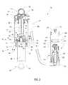
- FIG. 2is a cross-section of the rear shock absorber of FIG. 1 ;
- FIG. 3 ais an enlarged cross-section of a main portion of the shock absorber of FIG. 2 and FIG. 3 b is an enlarged cross-section of a reservoir of the shock absorber of FIG. 2 showing an inertia valve in a closed position;
- FIG. 4 ais a top plan view of the inertia mass of the shock absorber of FIG. 2 .
- FIG. 4 bis a side cross-section view of the inertia mass of FIG. 2 taken along line 4 b - 4 b in FIG. 4 a .
- FIG. 4 cis a bottom plan view of the inertia mass of FIG. 2 ;
- FIG. 5is an enlarged cross-section of the reservoir of the shock absorber of FIG. 2 , showing the inertia valve in an open position;
- FIG. 6is an enlarged cross-section of the inertia valve of the shock absorber of FIG. 2 ;
- FIG. 7 ais an enlarged view of a portion of the inertia valve of FIG. 6 .
- FIG. 7 bis an enlarged view of a portion of an alternative inertia valve;
- FIG. 8is a graph illustrating the relationship between position, velocity and acceleration for a simple mass
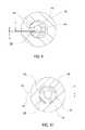
- FIG. 9is a schematic illustration of an inertia valve in an off-center condition
- FIG. 10is a schematic illustration of an inertia valve in a second off-center condition
- FIG. 11is a cross-section view of the inertia valve of FIG. 3 b showing various zones of cross-sectional fluid flow areas;
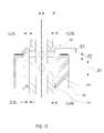
- FIG. 12is a cross-section view of the inertia valve of FIG. 3 b in an off-center condition
- FIG. 13is an enlarged view of an adjustable return fluid flow beneath the inertia mass
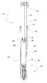
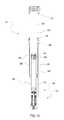
- FIG. 14is the front shock absorber, or suspension fork, of FIG. 1 as detached from the bicycle;
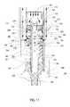
- FIG. 15is a cross-section view of the right leg of the fork of FIG 14 , illustrating various internal components
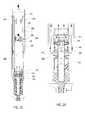
- FIG. 16is an enlarged cross-section of a lower portion of the fork leg of FIG. 15 , illustrating an inertia valve damping system
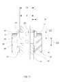
- FIG. 17is an enlarged cross-section of a base valve assembly of the lower portion of the fork leg of FIG. 16 ;
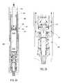
- FIG. 18is a cross-section view of the lower portion of the fork of FIG. 15 , with the inertia valve in an open position;
- FIG. 19is the base valve assembly of FIG. 17 , with the inertia valve in an open position;
- FIG. 20is a cross-section view of the lower portion of the fork of FIG. 16 illustrating rebound fluid flow
- FIG. 21is the base valve assembly of FIG. 17 illustrating rebound fluid flow
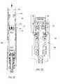
- FIG. 22is a cross-section view of a lower portion of an alternative embodiment of a suspension fork
- FIG. 23is an enlarged view of the base valve assembly of the fork of FIG. 22 , with the inertia valve in a closed position;
- FIG. 24is the lower portion of the fork of FIG. 22 , with the inertia valve in an open position;
- FIG. 25is the base valve assembly of FIG. 23 , with the inertia valve in an open position;
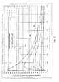
- FIG. 26is a graph of the pressure differential of fluid acting on the left and right sides of the inertia mass versus internal diameter of the inertia mass;
- FIG. 27is a graph of the pressure differential factor of fluid acting on the left and right sides of the inertia mass versus the internal diameter of the inertia mass for a radial gap between the inertia mass and shaft of 0.002 inches;
- FIG. 28is a graph of the pressure differential factor of fluid acting on the left and right sides of the inertia mass versus the internal diameter of the inertia mass for a radial gap between the inertia mass and shaft of 0.001 inches.
- FIG. 29is an enlarged, cross-section view of an alternative inertia valve assembly comprising an inertia mass having increased density, in comparison to the embodiments of FIGS. 1-28 , in order to provide increased responsiveness to acceleration forces.
- FIG. 30is an enlarged view of an alternative embodiment of an inertia mass including a plurality of drag members to increase the fluid drag on the inertia mass when moving in one direction in comparison with the drag on the inertia mass during movement in the opposite direction.
- FIG. 31Ais a cross-section view of the inertia mass of FIG. 30 illustrating an orientation of the drag members when the inertia mass is moving in a downward direction within a fluid-filled reservoir chamber.
- FIG. 31Bis a cross-section view of the inertia mass of FIG. 30 illustrating an orientation of the drag members when the inertia mass is moving in an upward direction within a fluid-filled reservoir chamber.
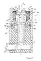
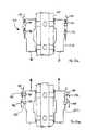
- FIG. 32is an enlarged, cross-section view of a pressure-responsive inertia valve assembly.
- FIG. 33is an enlarged, cross-section view of another embodiment of a pressure-responsive inertia valve assembly.
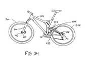
- FIG. 34is a side elevational view of bicycle employing yet another embodiment of an acceleration-sensitive shock absorber.
- FIG. 35is an enlarged, cross-section view of an acceleration-sensitive valve assembly within a shock absorber of the bicycle of FIG. 35 .
- the inertia valve assembly of FIG. 30includes a valve body that is at least partially controlled by an electromagnetic system.
- FIG. 1illustrates an off-road bicycle, or mountain bike, 20 including a frame 22 which is comprised of a main frame portion 24 and a swing arm portion 26 .
- the swing arm portion 26is pivotally attached to the main frame portion 24 .
- the bicycle 20includes front and rear wheels 28 , connected to the main frame 24 .
- a seat 32is connected to the main frame 24 and provides support for a rider of the bicycle 20 .
- the front wheel 28is supported by a preferred embodiment of a suspension fork 34 which, in turn, is secured to the main frame 24 by a handlebar assembly 36 .
- the rear wheel 30is connected to the swing arm portion 26 of the frame 22 .
- a preferred embodiment of a rear shock 38is operably positioned between the swing arm 26 and the main frame 24 to provide resistance to the pivoting motion of the swing arm 26 .
- the illustrated bicycle 20includes suspension members 34 , 38 between the front and rear wheels 28 , 30 and the frame 22 , which operate to substantially reduce wheel impact forces from being transmitted to the rider of the bicycle 20 .
- the rear shock absorber 38desirably includes a fluid reservoir 44 hydraulically connected to the main shock body by a hydraulic hose 46 .
- the reservoir 44is connected to the swingarm portion 26 of the bicycle 20 above the hub axis of the rear wheel 30 .
- the suspension fork 34 and the rear shock 38preferably include an acceleration-sensitive valve, commonly referred to as an inertia valve, which allows the damping rate to be varied depending upon the direction of an acceleration input.
- the inertia valvepermits the suspension fork 34 and rear shock 38 to distinguish between accelerations originating at the sprung mass, or main frame 24 and rider of the bicycle 20 , from accelerations originating at the unsprung mass, or front wheel 28 and rear wheel 30 , and alter the damping rate accordingly. It is generally preferred to have a firm damping rate when accelerations originate at the sprung mass and a softer damping rate when the accelerations originate at the unsprung mass. On an automobile or other four-wheel vehicle, this helps to stabilize the body by reducing fore and aft pitching motions during acceleration and braking, as well as by reducing body roll during cornering.
- the inertia valving within the suspension fork 34 and rear shock 38include features which permit responsive, consistent performance and allow such inertia valves to be manufactured in a cost effective manner.
- the inertia valveis located within the reservoir 44 , which may be rotated relative to the swingarm portion 26 of the bicycle 20 . Rotating the reservoir 44 alters the component of an upward acceleration of the rear wheel 30 which acts along the axis of motion of the inertia valve and thereby influences the responsiveness of the inertia valve.
- FIGS. 2-7illustrate a preferred embodiment of the rear shock absorber 38 .
- a shock absorber 38operates as both a suspension spring and as a damper.
- the springis an air spring arrangement, but coil springs and other suitable arrangements may also be used.
- the shock 38is primarily comprised of an air sleeve 40 , a shock body 42 and a reservoir 44 .
- a hydraulic hose 46physically connects the main body of the shock 38 (air sleeve 40 and shock body 42 ) to the reservoir 44 .
- the reservoir 44may also be directly connected to the main body of the shock absorber 38 , such as being integrally connected to, or monolithically formed with, the air sleeve 40 .
- the air sleeve 40is cylindrical in shape and includes an open end 48 and an end closed by a cap 50 .
- the cap 50 of the air sleeve 40defines an eyelet 52 which is used for connection to the main frame 24 of the bicycle 20 of FIG. 1 .
- the open end 48 of the air sleeve 40slidingly receives the shock body 42 .
- the shock body 42is also cylindrical in shape and includes an open end 54 and a closed end 56 .
- the closed end 56defines an eyelet 58 for connecting the shock 38 to the swing arm portion 26 of the bicycle 20 of FIG. 1 .
- the air sleeve 40 and the shock body 42are configured for telescopic movement between the main frame portion 24 and the swing arm portion 26 of the bicycle 20 . If desired, this arrangement may be reversed and the shock body 42 may be connected to the main frame 24 while the air sleeve 40 is connected to the swing arm 26 .
- a seal assembly 60is positioned at the open end 48 of the air sleeve 40 to provide a substantially airtight seal between the air sleeve 40 and the shock body 42 .
- the seal assembly 60comprises a body seal 62 positioned between a pair of body bearings 64 .
- the illustrated body seal 62is an annular seal having a substantially square cross-section. However, other suitable types of seals may also be used.
- a wiper 66is positioned adjacent the open end 48 of the air sleeve 40 to remove foreign material from the outer surface of the shock body 42 as it moves into the air sleeve 40 .
- a damper piston 68is positioned in sliding engagement with the inner surface of the shock body 42 .
- a shock shaft 70connects the piston 68 to the cap 50 of the air sleeve 40 .
- the damper piston 68is fixed for motion with the air sleeve 40 .
- a piston cap 72is fixed to the open end 54 of the shock body 42 and is in sliding engagement with both the shock shaft 70 and the inner surface of the air sleeve 40 .
- the piston cap 72supports a seal assembly 74 comprised of a seal member 76 positioned between a pair of bearings 78 .
- the seal assembly 74is in a sealed, sliding engagement with the inner surface of the air sleeve 40 .
- a shaft seal arrangement 80is positioned to create a seal between the cap 72 and the shock shaft 70 .
- the shaft seal arrangement 80comprises a seal member 82 and a bushing 84 .
- the seal member 82is an annular seal with a substantially square cross-section, similar to the body seal 62 .
- the shaft seal arrangement 80creates a substantially airtight seal between the cap 72 and the shock shaft 70 while allowing relative sliding motion therebetween.
- a positive air chamber 86is defined between the closed end 50 of the air sleeve 40 in the cap 72 . Air held within the positive air chamber 86 exerts a biasing force to resist compression motion of the shock absorber 38 . Compression motion of the shock absorber 38 occurs when the closed ends 56 and 50 of the shock body 42 and air sleeve 40 (and thus the eyelets 52 , 58 ) move closer to one another.
- a negative air chamber 88is defined between the cap 72 and the seal assembly 60 , which in combination with the shock body 42 closes the open end 48 of the air sleeve 40 . Air trapped within the negative air chamber 88 exerts a force which resists expansion, or rebound, motion of the shock absorber 38 . Rebound motion of the shock absorber 38 occurs when the closed ends 56 and 50 of the shock body 42 and air sleeve 40 (and thus the eyelets 52 , 58 ) move farther apart from each other. Together, the positive air chamber 86 and the negative air chamber 88 function as the suspension spring portion of the shock absorber 38 .
- An air valve 90communicates with the positive air chamber 86 to allow the air pressure therein to be adjusted. In this manner, the spring rate of the shock absorber 38 may be easily adjusted.
- a bypass valve 92is provided to allow the pressure between the positive air chamber 86 and the negative air chamber 88 to be equalized.
- the bypass valve 92is configured to allow brief communication between the positive air chamber 86 and the negative air chamber 88 when the air sleeve seal assembly 74 passes thereby.
- a bottom out bumper 94is positioned near the closed end 50 of the air sleeve 40 to prevent direct metal to metal contact between the closed end 50 and the cap 72 of the shock body 42 upon full compression of the shock absorber 38 .
- the shock absorber 38also includes a damper assembly, which is arranged to provide a resistive force to both compression and rebound motion of the shock absorber 38 .
- the shock absorber 38provides modal response compression damping. That is, the shock absorber 38 preferably operates at a first damping rate until an appropriate acceleration input is sensed, then the shock absorber 38 operates at a second damping rate for a predetermined period thereafter, before returning the first damping rate. This is in opposition to a system that attempts to continually respond to instantaneous input. Such a modal system avoids the inherent delay associated with responding separately to each input event.
- the piston 68divides the interior chamber of the shock body 42 into a compression chamber 96 and a rebound chamber 98 .
- the compression chamber 96is defined between the piston 68 and the closed end 56 of the shock body 42 and decreases in volume during compression motion of the shock absorber 38 .
- the rebound chamber 98is defined between the piston 68 and the piston cap 72 , which is fixed to the open end 54 of the shock body 42 . The rebound chamber 98 decreases in volume upon rebound motion of the shock absorber 38 .
- the piston 68includes one or more axial compression passages 104 that are covered on the rebound chamber 98 side by a shim stack 106 .
- the shim stack 106is made up of one or more flexible shims and deflects to allow flow through the compression passages 104 during compression motion of the shock absorber 38 but prevents flow through the compression passages 104 upon rebound motion of the shock absorber 38 .
- the piston 68includes one or more rebound passages 108 extending axially therethrough.
- a rebound shim stack 110is made up of one or more flexible shims, and deflects to allow flow through the rebound passages 108 upon rebound motion of the shock absorber 38 while preventing flow through the rebound passages 108 during compression motion of the shock absorber 38 .
- a central passage 112 of the shock shaft 70communicates with the compression chamber 96 through the hollow fastener 100 .
- the passage 112also communicates with the interior chamber of the reservoir 44 through a passage 114 defined by the hydraulic hose 46 .
- the flow of hydraulic fluidis selectively permitted between the compression chamber 96 and the reservoir 44 .
- a rebound adjustment rod 116extends from the closed end 50 of the air sleeve 40 and is positioned concentrically within the passage 112 of the shock shaft 70 .
- the rebound adjustment rod 116is configured to alter the amount of fluid flow upon rebound motion thereby altering the damping force produced.
- An adjustment knob 118engages the rebound adjustment rod 116 and is accessible externally of the shock absorber 38 to allow a user to adjust the rebound damping rate.
- a ball detent mechanism 120operates in a known manner to provide distinct adjustment positions of the rebound damping rate.
- the reservoir 44includes a reservoir tube 122 closed on either end.
- a floating piston 124is in sliding engagement with the interior surface of a reservoir tube 122 .
- a seal member 126provides a substantially fluid-tight seal between the piston 124 and the interior surface of the reservoir tube 122 .
- the seal member 126is preferably an annular seal having a substantially square cross-section. However, other suitable seals may also be used.
- the floating piston 124divides the interior chamber of the reservoir tube 122 into a reservoir chamber 128 and a gas chamber 130 .
- the reservoir chamber 128 portion of the reservoir tubeis closed by an end cap 132 .
- the end cap 132additionally receives the end of the hydraulic hose 46 and supports a hollow reservoir shaft 134 .
- the central passage 136 of the reservoir shaft 134is in fluid communication with the passages 114 and 112 and, ultimately, the compression chamber 96 .
- the reservoir shaft 134supports an inertia valve assembly 138 and a blowoff valve assembly 140 .
- Each of the inertia valve assembly 138 and the blowoff valve assembly 140allows selective communication between the compression chamber 96 , via the passages 112 , 114 , 136 , and the reservoir chamber 128 .
- the gas chamber 130 end of the reservoir tube 122is closed by a cap 142 which includes a valve assembly 144 for allowing gas, such as nitrogen, for example, to be added or removed from the gas chamber 130 .
- gassuch as nitrogen, for example.
- the pressurized gas within the gas chamber 130causes the floating piston 124 to exert a pressure on the hydraulic fluid within the reservoir chamber 128 . This arrangement prevents air from being drawn into the hydraulic fluid and assists in refilling fluid into the compression chamber 96 during rebound motion of the shock absorber 38 .
- the blowoff valve assembly 140is supported by the reservoir shaft 134 and positioned above the inertia valve assembly 138 .
- the reservoir shaft 134reduces in diameter to define a shoulder portion 154 .
- An annular washer 156is supported by the shoulder 154 and the blowoff valve assembly 140 is supported by the washer 156 .
- the washer 156also prevents direct contact between the inertia mass 150 and the blowoff valve assembly 140 .
- the blowoff valve assembly 140is primarily comprised of a cylindrical base 158 and the blowoff cap 160 .
- the base 158is sealed to the reservoir shaft 134 by a shaft seal 162 .
- the illustrated seal 162is an O-ring, however other suitable seals may also be used.
- the upper end of the base 158is open and includes a counterbore which defines a shoulder 164 .
- the blowoff cap 160is supported by the shoulder 164 and is sealed to the inner surface of the base 158 by a cap seal 166 .
- the cap seal 166is preferably an O-ring, however other suitable seals may also be used.
- a threaded fastener 168fixes the blowoff cap 160 and base 158 to the reservoir shaft 134 .
- the blowoff cap 160 and base 158define a blowoff chamber 170 therebetween.
- a plurality of radial fluid flow passages 172are defined by the reservoir shaft 134 to allow fluid communication between the blowoff chamber 170 and the shaft passage 136 .
- the blowoff cap 160includes one or more axial blowoff passages 174 and one or more axial refill passages 176 .
- a blowoff shim stack 178is positioned above the blowoff cap 160 and covers the blowoff passages 174 .
- the blowoff shim stack 178is secured in place by the threaded fastener 168 .
- the individual shims of the shim stack 178are capable of deflecting about the central axis of the fastener 168 to selectively open the blowoff passages 174 and allow fluid communication between the blowoff chamber 170 and the reservoir chamber 128 .
- the blowoff shim stack 178is preferably configured to open in response to pressures within the blowoff chamber above a minimum threshold, such as approximately 800 psi, for example.
- a refill shim stack 180is positioned between the blowoff cap 160 and the reservoir shaft 134 and covers the refill ports 176 .
- the refill shim stack 180is configured to prevent fluid from flowing from the blowoff chamber 170 through ports 176 to the reservoir 128 while offering little resistance to flow from the reservoir 128 into the blowoff chamber 170 .
- the inertia valve assembly 138includes a plurality of radially extending, generally cylindrical valve passages 148 , connecting the passage 136 to the reservoir chamber 128 .
- the inertia valve assembly 138also includes a valve body, or inertia mass 150 , and a spring 152 .
- the spring 152biases the inertia mass 150 into an upward, or closed, position wherein the inertia mass 150 covers the mouths of the valve passages 148 to substantially prevent fluid flow from the passage 136 to the reservoir chamber 128 .
- the inertia mass 150is also movable into a downward, or open, position against the biasing force of the spring 152 . In the open position, the inertia mass 150 uncovers at least some of the valve passages 148 to allow fluid to flow therethrough.
- the end cap 132which closes the lower end of the reservoir tube 122 , defines a cylindrical pocket, or socket, 182 which receives the inertia mass 150 in its lowermost or open position.
- the lowermost portion of the pocket 182reduces in diameter to form a shoulder 184 .
- the shoulder 184operates as the lowermost stop surface, which defines the open position of the inertia mass 150 , as illustrated in FIG. 5 .
- the inertia mass 150includes a check plate 190 which allows fluid to be quickly displaced from the pocket 182 as the inertia mass 150 moves downward into the pocket 182 .
- the inertia mass 150has a plurality of axial passages 188 extending therethrough.
- the check plate 190rests on several projections, or standoff feet, 192 ( FIG. 6 ) slightly above the upper surface of the inertia mass 150 and substantially covers the passages 188 .
- a series of stop projections 193similar to the standoff feet, are formed or installed in the upper, necked portion of the inertia mass 150 to limit upward motion of the check plate 190 .
- the axial passages 188are preferably kidney-shaped, to allow the passages 188 to occupy a large portion of the transverse cross-sectional area of the inertia mass 150 .
- the ratio of the passage 188 cross-sectional area to the inertia mass 150 cross-sectional areais greater than approximately 0.3.
- the ratio of the passage 188 cross-sectional area to the inertia mass 150 cross-sectional areais greater than approximately 0.5, and more preferably greater than approximately 0.7.
- the large area of the passages 188provides a low-resistance flow path for hydraulic fluid exiting the pocket 182 .
- the flow rate of the fluid exiting the pocket 182is high, and the inertia mass is able to move rapidly into the open position.
- the amount of fluid which must be displaced by the inertia mass 188 for it to move into the open positionis reduced.
- such an arrangementallows the inertia mass 150 to respond rapidly to acceleration forces.
- the check plate 190When the check plate 190 is resting against the standoff feet 192 on the upper surface of the inertia mass 150 it provides restricted fluid flow through the passages 188 .
- the check plate 190also has an open position in which it moves upward relative to the inertia mass 150 until it contacts the stop projections 193 . When the check plate 190 is open, fluid is able to flow from the pocket 182 through the passages 188 and into the reservoir 128 , with desirably low resistance.
- the inertia mass 150also includes a third series of projections, or standoff feet, 194 .
- the standoff feet 194are comprised of one or more projections located on the uppermost surface of the upper neck portion of the inertia mass 150 .
- the standoff feet 194 on the upper surface of the neck portion of the inertia mass 150contact the washer 156 when the inertia mass 150 is in its uppermost or closed position.
- a fourth set of projections, or standoff feet, 195are positioned on the lower surface of the inertia mass 150 ( FIG. 4 c ) and contact the shoulder 184 when the inertia mass 150 is in its lower or open position.
- each set of stop projections, or standoff feet, 192 - 195preferably between three to five individual projections are disposed radially about the inertia mass 150 .
- the surface area of the stop projections, or standoff feet, 192 - 195is relatively small.
- a small surface area of the standoff feet 194 , 195lowers the resistance to movement of the inertia mass 150 by reducing the overall surface contact area between the inertia mass 150 and the washer 156 or shoulder 184 , respectively.
- the small surface area of the standoff feet 192 and stop projections 193lower the resistance to movement of the check plate 190 relative to the inertia mass 150 .
- the projections 192 - 195have dimensions of less than approximately 0.025′′ ⁇ 0.025′′.
- the projections 192 - 195have dimensions of less than approximately 0.020′′ ⁇ 0.020′′ and, more preferably, the projections 192 - 195 have dimensions of less than approximately 0.015′′ ⁇ 0.015′′.
- the preferred projections 192 - 195provide a desirable ratio of the mass (weight) of the inertia valve mass 150 to the contact surface area of the projections 192 - 195 . Due to the vacuum effect between two surfaces, a force of approximately 14.7 lbs/in 2 (i.e., atmospheric pressure) is created when attempting to separate the inertia mass 150 from either the washer 156 or shoulder 184 , respectively. By lowering the contact surface area between the inertia mass 150 and either the washer 156 or shoulder 184 , the vacuum force tending to resist separation of the contact surfaces is desirably reduced.
- the contact surface areais small in comparison with the mass (weight) of the inertia mass 150 because the magnitude of the acceleration force acting on the inertia mass 150 is proportional to it's mass (weight). Accordingly, a large ratio of the mass (weight) of the inertia valve mass 150 to the contact surface area of the projections 192 - 195 is desired.
- the ratiois at least approximately 17 lbs/in 2 .
- a more desirable ratiois at least approximately 25 lbs/in 2 .
- the ratiois at least 50 lbs/in 2 and more preferably is at least 75 lbs/in 2 .
- ratiosare desirable for an inertia mass utilized in the context of an off-road bicycle rear shock absorber and other ratios may be desirable for other applications and/or vehicles.
- higher ratiosincrease the sensitivity of the inertia mass 150 (i.e., allow the inertia mass 150 to be very responsive to acceleration forces).
- the sensitivity of the inertia mass 150is about +/ ⁇ 1 ⁇ 3 G.
- the sensitivity of the inertia mass 150is about +/ ⁇ 1/10 G.
- the outside diameter of the lower portion of the inertia mass 150is slightly smaller than the diameter of the pocket 182 . Therefore, an annular clearance space is defined between them when the inertia mass 150 is positioned within the pocket 182 .
- the clearance Crestricts the rate with which fluid may pass to fill the pocket below the inertia mass 150 , to influence the rate at which the inertia mass 150 may exit the pocket 182 .
- a fluid suction forceis applied to the inertia mass 150 within the pocket 182 to delay the inertia mass 150 from returning to the closed position.
- the interior surface of the inertia mass 150includes an increased diameter central portion 195 which, together with the shaft 134 , defines an annular recess 196 .
- the annular recess 196is preferably located adjacent to one or more of the ports 148 when the inertia mass 150 is in its closed position. Thus, fluid exiting from the shaft passage 136 through the passages 148 enters the annular recess 196 when the inertia mass 150 is its closed position.
- the interior surface of the inertia mass 150decreases in diameter both above and below the central portion 195 to create an upper intermediate portion 197 and a lower intermediate portion 199 .
- the upper intermediate portion 197 and lower intermediate portion 199together with the shaft 134 , define an upper annular clearance 198 ( FIG. 7 a ) and a lower annular clearance 200 , respectively.
- An upper lip 201( FIG. 7 a ) is positioned above, and is of smaller diameter than, the upper intermediate portion 197 .
- a step 205( FIG. 7 a ) is defined by the transition between the upper intermediate portion 197 and the upper lip 201 .
- a lower lip 203is positioned below, and has a smaller diameter than, the lower intermediate portion 199 .
- a step 205is defined by the transition between the lower intermediate portion 199 and the lower lip 203 .
- the upper lip 201 and the lower lip 203together with the shaft 134 , define an upper exit clearance 202 ( FIG. 7 a ) and a lower exit clearance 204 .
- the upper lip 201preferably includes a labyrinth seal arrangement 206 .
- a labyrinth sealcomprises a series of annular grooves formed into a sealing surface.
- the lower lip 203also includes a labyrinth seal arrangement substantially similar to the labyrinth seal 206 of the upper lip 201 .
- the labyrinth seal arrangement 206reduces fluid flow (bleed flow) between the reservoir shaft 134 and the upper lip 201 when the inertia mass 150 is in a closed position. Excessive bleed flow is undesired because it reduces the damping rate when the inertia valve 138 is closed.
- the clearance between the inertia mass 150 and the shaft 134may be increased, without permitting excessive bleed flow.
- the increased clearanceis particularly beneficial to prevent foreign matter from becoming trapped between the inertia mass 150 and shaft 134 and thereby inhibiting operation of the inertia valve 138 .
- reliability of the shock absorber 38is increased, while the need for routine maintenance, such as changing of the hydraulic fluid, is decreased.
- FIG. 7 ban alternative inertia mass 150 is illustrated.
- the upper intermediate portion 197 of the inner surface of the inertia mass 150 of FIG. 7 bis inclined with respect to the outer surface of the shaft 134 , rather than being substantially parallel to the outer surface of the shaft 134 as in the inertia mass of FIG. 7 a .
- the step 205is effectively defined by the entire upper intermediate portion 197 .
- the inertia mass 150 configuration of FIG. 7 btheoretically provides approximately one-half the self-centering force of the inertia mass 150 of FIG. 7 a .
- the inner surface of the inertia mass 150may be utilized to provide a suitable self-centering force, as will be apparent to one of skill in the art based on the disclosure herein.
- the inclined surfacemay begin in an intermediate point of the upper intermediate portion 197 .
- the step 205may be chamfered, rather than orthogonal.
- the shock absorber 38is operably mounted between the main frame 24 and the swing arm portion 26 of the bicycle 20 and is capable of both compression and rebound motion.
- the shock body 42 portion of the shock absorber 38is connected to the swing arm portion 26 and the air sleeve 40 is connected to the main frame 24 .
- the reservoir 44is desirably connected to the swing arm portion 26 of the bicycle 20 preferably near the rear axle, and preferably approximately vertical as shown in FIG. 1 .
- the swing arm portion 26articulates with respect to the main frame 24 , tending to compress the shock absorber 38 . If the acceleration imparted along the longitudinal axis of the reservoir 44 is below a predetermined threshold, the inertia mass 150 will remain in its closed position, held by the biasing force of the spring 152 , as illustrated in FIG. 3 b.
- the blowoff shims 178open to allow fluid to flow from the blowoff chamber 170 through the blowoff ports 174 and into the reservoir 128 .
- a predetermined thresholdsuch as 800 psi for example
- the inertia mass 150If the upward acceleration imposed along the longitudinal axis of the reservoir 44 (i.e., the axis of travel of the inertia mass 150 ) exceeds the predetermined minimum threshold, the inertia mass 150 , which tends to remain at rest, will overcome the biasing force of the spring 152 as the reservoir 44 moves upward relative to the inertia mass 150 . If the upward distance of travel of the reservoir 44 is sufficient, the inertia mass will move into the pocket 182 . With the inertia mass 150 in the open position, fluid is able to be displaced from the compression chamber 96 through the passages 112 , 114 and the shaft passage 136 , through the passages 148 and into the reservoir 128 . Thus, the shock 38 is able to compress with the compression damping force again being determined by flow through the compression ports 104 of the piston 68 .
- the predetermined minimum threshold for the inertia mass 150 to overcome the biasing force of the spring 152is determined primarily by the mass of the inertia mass 150 , the spring rate of the spring 152 and the preload on the spring 152 . Desirably, the mass of the inertia mass is approximately 0.5 ounces. However, for other applications, such as the front suspension fork 34 or vehicles other than off-road bicycles, the desired mass of the inertia mass 150 may vary.
- the spring rate of the spring 152 and the preload on the spring 152are preferably selected such that the spring 152 biases the inertia mass 150 into a closed position when no upward acceleration is imposed along the longitudinal axis of the reservoir 44 .
- the inertia mass 150will desirably overcome the biasing force of the spring 152 upon experiencing an acceleration which is between 0.1 and 3 times the force of gravity (G's).
- G'sforce of gravity
- the inertia mass 150will overcome the biasing force of the spring 152 upon experiencing an acceleration which is between 0.25 and 1.5 G's and more preferably upon experiencing an acceleration which is between 0.4 and 0.7 G's.
- the predetermined thresholdmay be varied from the values recited above.
- the check plate 190 resting on the standoff feet 193 of the inertia mass 150allows fluid to be easily displaced upward from the pocket 182 and thus allows the inertia mass 150 to move into the pocket 182 with little resistance. This permits the inertia mass 150 to be very responsive to acceleration inputs. As the inertia mass 150 moves into the pocket 182 , fluid within the pocket 182 flows through the passages 188 and lifts the check plate 190 against the stop projections 193 .
- the spring 152exerts a biasing force on the inertia mass 150 tending to move it from the pocket 182 .
- Fluid pressure above the inertia mass 150causes the check plate 190 to engage the standoff feet 192 located on the upper surface of the inertia mass 150 restricting flow through the ports 188 .
- the height of the standoff feet 192 which the check plate 190 rests onis typically 0.003′′ to 0.008′′ above the exit surface of the passages 188 to provide an adequate level of flow restriction upon upward movement of the inertia mass 150 .
- Fluidmay be substantially prevented from flowing through the passages 188 and into the pocket 182 , except for a small amount of bleed flow between the checkplate 190 and the upper surface of the inertia mass 150 .
- the height of the standoff feet 192may be altered to influence the flow rate of the bleed flow and thereby influence the timer feature of the inertia mass 150 , as will be described below.
- Fluidalso enters the pocket 182 through the annular clearance, or primary fluid flow path, C ( FIG. 6 ) between the interior surface, or valve seat, of the pocket 182 and the exterior surface of the inertia mass 150 .
- the size of the clearance Calso influences the rate at which fluid may enter the pocket 182 thereby allowing the inertia mass 150 to move upward out of the pocket 182 .
- the inertia mass 150once the inertia mass 150 is moved into an open position within the pocket 182 , it remains open for a predetermined period of time in which it takes fluid to refill the pocket behind the inertia mass 150 through the clearance C.
- Thisis referred to as the “timer feature” of the inertia valve assembly 138 .
- this period of timecan be independent of fluid flow direction within the shock absorber 38 .
- the shock absorber 38may obtain the benefits of a reduced compression damping rate throughout a series of compression and rebound cycles, referred to above as “modal response.”
- the inertia mass 150remains in an open position for a period between approximately 0.05 and 5 seconds, assuming no subsequent activating accelerations are encountered.
- the inertia mass 150remains in an open position for a period between about 0.1 and 2.5 seconds and more preferably for a period between about 0.2 and 1.5 seconds, again, assuming no subsequent accelerations are encountered which would tend to open the inertia mass 150 , thus lengthening or resetting the timer period.
- the above valuesare desirable for a rear shock absorber 38 for an off-road bicycle 20 .
- the recited valuesmay vary in other applications, however, such as when adapted for use in the front suspension fork 34 or for use in other vehicles or non-vehicular applications.
- FIG. 8the relationship between vertical position P, vertical velocity V and vertical acceleration A, over time T, for a simple mass traversing two sinusoidally-shaped bumps is illustrated.
- FIG. 8is based on a mass that travels horizontally at a constant velocity, while tracking vertically with the terrain contour.
- This physical modelsomewhat simplified for clarity, correctly represents the essential arrangement utilized in inertia-valve shock absorbers wherein the inertial element is shaft-mounted and spring-biased within the unsprung mass.
- the heavy solid line indicating position Prepresents both the trail surface and, assuming the wheel of the bicycle is rigid and remains in contact with the trail surface, the motion of any point on the unsprung portion of the bicycle, such as the hub axis of the front or rear wheel, for example.
- the lines representing velocity V and acceleration Athus correspond to the vertical velocity and acceleration of the hub axis.
- the trail surface (solid line indicating position P)includes a first bump B 1 and a second bump B 2 . In this example, as shown, each bump is preceded by a short section of smooth (flat) terrain.
- the acceleration A of the hub axis Hrises sharply to a maximum value and, accordingly, the velocity V of the hub axis H increases.
- the acceleration as shownis calculated as the second derivative of the sinusoidal bump curve, and the velocity as the first derivative.
- the second derivative(acceleration A) becomes negative (changes direction) and the velocity begins to decrease from a maximum value.
- the acceleration Ais at a minimum value (i.e., large negative value) and the velocity V is at zero.
- the acceleration Ahas again changed direction and the velocity V is at a minimum value (i.e., large negative value).
- the acceleration Ahas risen again to a momentary maximum value and the velocity V is zero.
- the second bump B 2is assumed to be sinusoidally-shaped like the first bump B 1 , but, as shown, to have somewhat greater amplitude.
- the relationship between position P, velocity V and acceleration Aare substantially identical to those of the first bump B 1 .
- the shock absorberBefore the inertia valve passages are open, the shock absorber operates at its initial, firm damping rate. This results in an undesirably firm damping rate, creating a “damping spike”, over the initial portion of the bump B 1 .
- the damping spikecontinues until the shaft has moved upward relative to the inertia mass a sufficient distance to open the valve passages.
- the amount of movement of the shaft relative to the inertia mass necessary to uncover the passagesis determined primarily by the size of the passages and the position of the uppermost surface of the inertia mass relative to the passages when the mass is in its fully closed position. This distance is referred to as the spike distance S D .
- the amount of time necessary for the inertia passages to be opened and to reduce the damping rateis dependent upon the shape of the bump and the spike distance S D . and is referred to as the spike time S T .
- the reduction of the damping rateis at least partially dependent upon the size of the passages and, therefore, it is difficult to reduce the spike time S T without reducing the spike distance S D which necessarily affects the achievable lowered damping rate.
- the inertia massbegins to close (i.e., move relatively upward) when the acceleration acting upon it either ceases, changes direction, or becomes too small to overcome the biasing force of the spring.
- the acceleration Abecomes zero at point P 1 , or at approximately the mid-point of the bump B 1 .
- a simple inertia valvebegins to close at, or before, the middle of the bump B 1 . Therefore, utilizing a simple inertia valve tends to return the shock absorber to its initial, undesirably firm damping rate after only about one-half of the up-portion of bump B 1 has been traversed.
- the operating sequence of the inertia valveis similar for the second bump B 2 and each bump thereafter.
- inertia valve arrangementsutilize the fluid flow during compression or rebound motion to hydraulically support the inertia valve in an open position once acceleration has ceased or diminished below the level necessary for the inertia valve to remain open from acceleration forces alone.
- these types of inertia valve arrangementsare dependent upon fluid flow and allow the inertia valve to close when, or slightly before, the compression or rebound motion ceases.
- a shock absorber using this type of inertia valve in the compression circuitcould experience a reduced damping rate from after the initial spike until compression motion ceases at, or near, the peak P 2 of the bump B 1 .
- the flow dependent inertia valvenecessarily reacts to specific terrain conditions. That is, the inertia mass responds to each individual surface condition and generally must be reactivated upon encountering each bump that the bicycle traverses. Therefore, this type of shock absorber experiences an undesirably high damping rate “spike” as each new bump is encountered.
- the inertia valve arrangement 138 of the present shock absorber 38is a modal response type. That is, the inertia valve 138 differentiates rough terrain conditions from smooth terrain conditions and alters the damping rate accordingly. During smooth terrain conditions, the inertia valve 138 remains in a closed position and the damping rate is desirably firm, thereby inhibiting suspension motion due to the movement of the rider of the bicycle 20 . When the first bump B 1 is encountered, the inertia valve 138 opens to advantageously lower the damping rate so that the bump may be absorbed by the shock absorber 38 .
- the timer featureretains the inertia valve 138 in an open position for a predetermined period of time thereby allowing the shock absorber 38 to maintain the lowered damping rate for the entire bump (not just the first half of the up-portion), and to furthermore absorb the second bump B 2 and subsequent bumps possibly without incurring any additional “spikes.”
- the timer featureis configured to delay the inertia mass 150 from closing until a period of time after completion of both the compression stroke and rebound stroke and, preferably, until after the beginning of the second compression stroke resulting from an adjacent bump.
- the timer periodmay be adjustable by altering the rate at which fluid may refill the timer pocket 182 .
- the spring force generated by the combination of the positive air chamber 86 and the negative air chamber 88tend to bias the shock body 42 away from the air sleeve 40 .
- a volume of fluid equal to the displaced volume of the shock shaft 70must be drawn from the reservoir 128 and into the compression chamber 96 . Fluid flow is allowed in this direction through the refill ports 176 in the blowoff valve 140 against a desirably light resistance offered by the refill shim stack 180 . Gas pressure within the gas chamber 130 exerting a force on the floating piston 124 may assist in this refill flow.
- the rebound damping rateis determined primarily by fluid flow through the rebound passages 108 against the biasing force of the rebound shim stack 110 .
- the fluid flow path during compression or rebound motion of the shock absorber 38is above and away from the inertia mass 150 itself
- such an arrangementsubstantially isolates fluid flow from coming into contact with the inertia mass 150 , thereby inhibiting undesired movement of the inertia mass due to drag forces resulting from fluid flow.
- the inertia mass 150advantageously responds to acceleration inputs and is substantially unaffected by the movement of hydraulic fluid during compression or rebound of the shock absorber 38 .
- the present shock absorber 38includes an inertia valve 138 comprising a self-centering valve body, or inertia mass 150 .
- inertia valve 138comprising a self-centering valve body, or inertia mass 150 .
- FIGS. 9 and 10schematically illustrate an off-center condition of the inertia mass 150 relative to the shaft 134 .
- the off-center condition of the inertia mass 150may cause it to contact the shaft 134 causing friction, which tends to impede motion of the inertia mass 150 on the shaft 134 .
- Each of the off-center conditions illustrated in FIGS. 8 and 9may result from typical manufacturing processes. However, modifying the manufacturing process to avoid these conditions often results in a prohibitively high manufacturing cost.
- FIG. 9illustrates an inertia valve arrangement in which the inertia valve passages 148 are of slightly different diameter.
- a conditionis often an unavoidable result of the typical manufacturing process of drilling in a radial direction through a tubular piece of material. Such a process may result in an entry diameter N created by the drilling tool being slightly larger than the exit diameter X created by the drilling tool.
- the resulting difference in area between the passages 148causes the fluid pressure within the shaft passage 136 to exert an unequal force between the entry passage 148 having an entry diameter N and the exit passage 148 having an exit diameter X.
- a difference between the entry diameter N and the exit diameter X of only two thousandths of an inch (0.090′′ exit diameter versus 0.092′′ entry diameter) at a fluid pressure of 800 psiresults in a force differential of approximately 0.2 pounds, or 3.6 ounces, between the passages 148 .
- the inertia mass 150itself may weigh only about one half of an ounce (0.5 oz.). Such a force differential will push the inertia mass 150 off-center and reduce the responsiveness of the inertia mass 150 , if not prevent it from moving entirely.
- FIG. 10illustrates an off-center condition of the inertia mass 150 caused by the inertia valve passages 148 being positioned off-center relative to the shaft 134 .
- a center axis AC of the inertia valve passages 148is offset from the desired diametrical axis AD of the shaft 134 by a distance O. Therefore, the force resulting from fluid pressure within the shaft passage 136 does not act precisely on a diametrical axis AD of the inertia mass 150 , resulting in the inertia mass 150 being pushed off-center with respect to, and likely contacting, the shaft 134 .
- the offset condition of the center axis AC of the passages 148is the result of inherent manufacturing imperfections and cannot easily be entirely avoided, at least without raising the cost of manufacturing to an unfeasible level.
- the passages 148could be made with identical diameters and be positioned exactly along the diametrical axis AD of the shaft 134 , additional forces may tend to push the inertia mass 150 off-center.
- the reservoir 44experiences an acceleration which is not exactly aligned with the axis of travel of the inertia mass 150 (such as braking or forward acceleration)
- the transverse component of the accelerationwould create a force tending to move the inertia mass 150 off-center and against the shaft 134 .
- the transverse component of the accelerationis large enough, the resulting frictional force between the inertia mass 150 and the reservoir shaft 134 will inhibit, or prevent, movement of the inertia mass 150 . Accordingly, it is highly desirable to compensate for factors which tend to push the inertia mass 150 off-center in order to ensure responsive action of the inertia valve 138 . This is especially important in off-road bicycle applications, where it is desirable for the inertia valve assembly 138 to respond to relatively small accelerations and the mass of the inertia mass 150 is also relatively small.
- the inertia valve assembly 138preferably includes a self-centering inertia mass 150 .
- the inertia mass 150 of FIG. 5is shown without the fluid flow lines to more clearly depict the cross-sectional shape of its interior surface.
- the inertia mass 150has a minimum internal diameter “D” while the shaft 134 has a constant external diameter “d,” which is smaller than the internal diameter D.
- the difference between the shaft diameter d and the inertia valve diameter Dis desirably small.
- the bleed flow between the shaft 134 and the inertia mass 150undesirably reduces the damping rate which may be achieved when the inertia mass 150 is in a closed position.
- the difference between the shaft diameter d and the inertia mass diameter Dis desirably less than 0.01 inches.
- difference between the shaft diameter d and the inertia mass diameter Dis less than 0.004 inches and more preferably is approximately 0.002 inches.
- the difference between the shaft diameter d and the inertia mass diameter Dis desirably less than 0.02 inches.
- difference between the shaft diameter d and the inertia mass diameter Dis less than 0.008 inches and more preferably is approximately 0.004 inches.
- the recited valuesmay vary in other applications, however, such as when adapted for vehicles other than off-road bicycles or non-vehicular applications.
- the bleed ratemay be influenced by factors other than the difference between the shaft diameter d and the inertia mass diameter D. Accordingly, driven by a pressure differential of 400 psi, the bleed rate between the inertia mass 150 and the shaft 134 , for an off-road bicycle shock with a shaft diameter of 5 ⁇ 8 inches, is desirably less than 1.0 cubic inches/sec.
- the bleed rate between the inertia mass 150 and the shaft 134is less than 0.5 cubic inches/sec and more preferably is less than 0.3 cubic inches/sec.
- the preferred bleed ratesmay vary.
- annular recess 196is defined between the interior surface of the inertia mass 150 and the shaft 134 .
- the annular recess 196is preferably located in approximately the center of the inertia mass 150 .
- the annular recess 196is referred to as zone 1 (Z 1 ) in the following description of the fluid flow between the shaft 134 and the self-centering inertia mass 150 .
- the upper annular clearance 198above the annular recess 196 , is referred to as zone 2 (Z 2 ) and the upper exit clearance 202 is referred to as zone 3 (Z 3 ).
- the size B of the step 205(referred to as a “Bernoulli Step” in FIGS. 26 , 27 and 28 ) may be precisely manufactured by a computer controlled lathe operation, for example. Other suitable methods for creating a precisely sized step 205 may also be used.
- the outer surface of the shaft 134defines a first surface and the interior surface of the inertia mass 150 defines a second surface which faces the first surface.
- a first annular passageis defined by the upper annular clearance 198 and the upper exit clearance 202 .
- a first portion of the first annular passageis defined by the upper exit clearance 202 and a second portion of the first annular passage is defined by the upper annular clearance 198 .
- the first and second portionsdefine first and second cross-sectional flow areas of the first annular passage.
- a second annular passageis defined by the lower annular clearance 200 and the lower exit clearance 204 .
- a first portion of the second annular passageis defined by the lower exit clearance 204 and a second portion of the second annular passage is defined by the lower annular clearance 200 .
- the first and second portions of the second annular passagealso define first and second cross-sectional flow areas of the second annular passage.
- Zone 1 Z 1has a larger cross-sectional fluid flow area than zone 2 Z 2 which, in turn, has a larger cross-sectional flow area than zone 3 Z 3 .
- the cross-sectional area differential between the zones Z 1 , Z 2 , Z 3causes the fluid within each zone Z 1 , Z 2 , Z 3 to vary in velocity, which causes a self-centering force to be exerted on the inertia mass 150 when it becomes off-center, as will be described below.
- the zones Z 1 , Z 2 , Z 3are annular, the discussion below, for simplicity, is in the context of a two-dimensional structure having left and right sides. Accordingly, the zones Z 1 , Z 2 , Z 3 of the example will vary in cross-sectional distance, rather than in cross-sectional area.
- the exampleis simplified, it correctly describes the general self-centering action of the inertia mass 150 .
- Bernoulli's equationexpresses the law of conservation of energy for the flow of an incompressible fluid.
- the potential energy height) portion of Bernoulli's equationis not significant and may be ignored.
- the fluid pressure P 1 in zone 1is 400 psi, due to an external force tending to compress the shock absorber 38 and the fluid velocity V 1 is zero due to relatively little fluid exiting from zone 1 .
- the floating piston 124is absent or is not exerting a significant pressure on the fluid within the reservoir chamber 128 .
- the velocity V 3 of fluid exiting zone 3is 3,142 in/sec. Assuming the validity of assumptions inherent in Bernoulli's equation here, this value is true for all exit points of zone 3 Z 3 regardless of their dimensions. Further, based on flow continuity, the change in velocity of the fluid between zone 2 Z 2 and zone 3 Z 3 is proportional to the change in the clearance, or gap G, between zone 2 Z 2 and zone 3 Z 3 .
- the gap Gis the cross-sectional distance between the outer surface of the shaft 134 and the relevant inner surface of the inertia mass 150 .
- the force F acting on the inertia mass 150 in the above exampleis equal for the right and left side due to the velocity V 2 in zone 2 Z 2 being the same for each side.
- the velocity V 2is the same because the ratio of gap 3 G 3 to gap 2 G 2 between the right side and the left side is equal due to the inertia mass 150 being centered relative to the shaft 134 .
- the inertia mass 150becomes off center relative to the shaft 134 by a distance x, for example 0.001 inches to the left, the ratio of gap 3 G 3 to gap 2 G 2 is different between the right and left sides. This results in the velocity V 2 being different between the right and left sides and, as a result, a force differential between the right side and left side is produced.
- P 2300 psi
- F right ⁇ F left4.7 lbs. pushing right
- the lower portion of the inertia mass 150also includes a step 205 creating a lower zone 2 and zone 3 ( FIG. 12 ). Accordingly, a centering force acts on the lower portion of the inertia mass 150 when it is off-center from the shaft 134 .
- a force of as much as 4.7 lbsalso acts on the lower portion of the inertia mass 150 , resulting in a total centering force of as much as 9.4 lbs acting to center the inertia mass 150 relative to the shaft 134 .
- the ratio of the velocity in zone 2 V 2 to the velocity in zone 3 V 3is desirably between 0.9 and 0.2.
- the ratio of the velocity in zone 2 V 2 to the velocity in zone 3 V 3is desirably between 0.8 and 0.35 and more preferably the ratio of the velocity in zone 2 V 2 to the velocity in zone 3 V 3 is desirably between 0.75 and 0.5.
- Z 2influences the magnitude of the self-centering force produced by the inertia mass 150 .
- the ratio (G 3 /G 2 )is desirably less than one. If the ratio (G 3 /G 2 ) is equal to one, then by definition there is no step 205 between zone 2 Z 2 and zone 3 Z 3 .
- the ratio of the gap at Zone 3 to the gap at Zone 2is desirable between 0.90 and 0.20.
- the ratio of the gap at Zone 3 to the gap at Zone 2is desirably between 0.80 and 0.35 and more preferably the ratio of the gap at Zone 3 to the gap at Zone 2 is desirably between 0.75 and 0.50.
- the self-centering inertia mass 150is able to compensate for force differentials due to the manufacturing variations in the passage 148 size and position as well as transverse accelerations, all of which tend to push the inertia mass 150 off-center. This allows reliable, sensitive operation of the inertia valve assembly 140 while also permitting cost-effective manufacturing methods to be employed without compromising performance.
- zone 1 Z 1a fluid pressure in zone 1 Z 1 of 400 psi was used in the above example, the actual pressure may vary depending on the force exerted on the shock assembly 38 .
- the upper pressure limit in zone 1 Z 1is typically determined by the predetermined blow off pressure of the blow off valve 140 .
- the predetermined blow off pressureis approximately 400 psi.
- the predetermined blow off pressure within zone 1 Z 1is approximately 600 psi and more preferably is approximately 800 psi.
- FIG. 13illustrates an alternative arrangement for controlling the refill rate, or timer function, of fluid flow into the pocket 182 as the inertia mass 150 moves in an upward direction away from its closed position.
- the end cap 132includes a channel 208 communicating with an orifice 209 connecting the reservoir chamber 128 and the pocket 182 .
- the orifice 209permits fluid to flow between the reservoir chamber 128 and the pocket 182 in addition to the fluid flow through the clearance C and bleed flow between the check plate 190 and inertia mass 150 .
- the size of the orifice 209may be varied to influence the overall rate of fluid flow into the pocket 182 .
- FIG. 13also illustrates an adjustable pocket refill arrangement 210 .
- the adjustable refill arrangement 210allows external adjustment of the refill rate of fluid flow into the pocket 182 .
- the adjustable refill arrangementincludes an inlet channel 212 connecting the reservoir chamber 128 to a valve seat chamber 213 .
- An outlet channel 214connects the valve seat chamber 213 to the pocket 182 .
- a needle 215is positioned within the valve seat chamber 213 and includes a tapered end portion 216 , which extends into the outlet channel 214 to restrict the flow of fluid therethrough. External threads of the needle 215 engage internal threads of the end cap 132 to allow the needle 215 to move relative to the outlet channel 216 .
- the needle 215includes a seal 217 , preferably an O-ring, which creates a fluid tight seal between the needle 215 and the end cap 132 .
- the exposed end of the needle 215includes a hex-shaped cavity 218 for receiving a hex key to allow the needle 215 to be rotated.
- the exposed end of the needle 215may alternatively include other suitable arrangements that permit the needle 215 to be rotated by a suitable tool, or by hand. For example, an adjustment knob may be connected to the needle 215 to allow a user to easily rotate the needle without the use of tools.
- Rotation of the needle 215results in corresponding translation of the needle 215 with respect to the end cap 132 (due to the threaded connection therebetween) and adjusts the position of the tapered end 216 relative to the outlet channel 214 . If the needle 215 is moved inward, the tapered end 216 blocks a larger portion of the outlet channel 214 and slows the fluid flow rate into the pocket 182 . If the needle 215 is moved outward, the tapered end 216 reduces its blockage of the outlet channel 214 and speeds the fluid flow rate into the pocket 182 . This permits user adjustment of the refill rate of the pocket 182 and, accordingly, adjustment of the period of time the inertia mass 150 is held in an open position.
- the adjustable refill arrangement 210allows a user to alter the period of time the inertia valve 138 is open and thus, the period of lowered compression damping once the inertia valve 138 is opened.
- FIG. 14illustrates the suspension fork 34 detached from the bicycle 20 of FIG. 1 .
- the suspension fork 34includes right and left legs 220 , 222 , as referenced by a person in a riding position on the bicycle 20 .
- the right leg 220includes a right upper tube 224 telescoping received in a right lower tube 226 .
- the left leg 222includes a left upper tube 228 telescopingly received in a left lower tube 230 .
- a crown 232connects the right upper tube 224 to the left upper tube 228 thereby connecting the right leg 220 to the left leg 222 of the suspension fork 34 .
- the crown 232supports a steerer tube 234 , which passes through, and is rotatably supported by the frame 22 of the bicycle 20 .
- the steerer tube 234provides a means for connection of the handlebar assembly 36 to the suspension fork 34 , as illustrated in FIG. 1 .
- Each of the right lower tube 226 and the left lower tube 230includes a dropout 236 for connecting the front wheel 28 to the fork 34 .
- An arch 238connects the right lower tube 226 and the left lower tube 230 to provide strength and minimize twisting of the tubes 226 , 230 .
- the right lower tube 226 , left lower tube 230 , and the arch 238are formed as a unitary piece, however, the tubes 226 , 230 and the arch 238 may be separate pieces and connected by a suitable fastening method.
- the suspension fork 34also includes a pair of rim brake bosses 240 to which a standard rim brake assembly may be mounted.
- the fork 34may include a pair of disc brake bosses (not shown) to which a disc brake may be mounted.
- the suspension fork 34may include only one or the other of the rim brake bosses 240 and disc brake bosses, depending on the type of brake systems desired.
- FIG. 15is a cross-section view of the right leg 220 of the suspension fork 34 having the front portion cutaway to illustrate the internal components of a damping assembly 244 of the fork 34 .
- the left leg 222 of the suspension fork 34houses any of a known suitable suspension spring assembly.
- an air or coil spring arrangementmay be used.
- a portion of the suspension spring assemblymay be housed within the right fork leg 220 along with the damper assembly 244 .
- the upper tube 224is capable of telescopic motion relative to the lower tube 226 .
- the fork leg 220includes an upper bushing 246 and a lower bushing 248 positioned between the upper tube 224 and the lower tube 226 .
- the bushings 246 , 248inhibit wear of the upper tube 224 and the lower tube 226 by preventing direct contact between the tubes 224 , 226 .
- the bushings 246 , 248are affixed to the lower tube 226 and are made from a self-lubricating and wear-resistant material, as is known in the art.
- the bushings 246 , 248may be similarly affixed to the upper tube 224 .
- the bushings 246 , 248include grooves (not shown) that allow a small amount of hydraulic fluid to pass between the bushings 246 , 248 and the upper fork tube 224 to permit lubrication of the bushing 246 and seal, described below.
- the lower tube 226has a closed lower end and an open upper end.
- the upper tube 224is received into the lower tube 226 through its open upper end.
- a seal 250is provided at the location where the upper 224 enters the open end of the lower tube 226 and is preferably supported by the lower tube 226 and in sealing engagement with the upper tube 224 to substantially prevent oil from exiting, or a foreign material from entering the fork leg 220 .
- the damping assembly 244is operable to provide a damping force in both compression and a rebound direction to slow both compression and rebound motion of the fork 34 .
- the damper assembly 244is preferably an open bath, cartridge-type damper assembly having a cartridge tube 252 fixed with respect to the closed end of the lower tube 226 and extending vertically upward.
- a damper shaft 254extends vertically downward from a closed upper end of the upper tube 224 and supports a piston 258 .
- the piston 258is fixed for movement with the upper tube 224 while the cartridge tube 252 is fixed for movement with the lower tube 226 .
- the piston 258is positioned within the cartridge tube 252 and is in telescoping engagement with the inner surface of the cartridge tube 252 .
- a cartridge tube cap 260closes the upper end of the cartridge tube 252 and is sealing engagement with the damper shaft 254 .
- the cartridge tube 252defines a substantially sealed internal chamber which contains the piston 258 .
- the piston 258divides the internal chamber of the cartridge tube 252 into a variable volume rebound chamber 262 and a variable volume compression chamber 264 .
- the rebound chamber 262is positioned above the piston 258 and the compression chamber 264 is positioned below the piston 258 .
- a reservoir 266is defined between the outer surface of the cartridge tube 252 and the inner surfaces of the upper and lower tubes 224 , 226 .
- a base valve assembly 268is operably positioned between the compression chamber 264 and the reservoir 266 and allows selective communication therebetween.
- FIG. 16is an enlarged cross section of the damping assembly 244 .
- a cartridge tube cap 260closes the upper end of the cartridge tube 252 .
- An outer seal 270creates a seal between the cartridge tube cap 260 and the cartridge tube 252 while an inner seal 272 creates a seal between the cartridge tube cap 260 and the damper shaft 254 . Accordingly, extension and retraction of the damper shaft 254 with respect to the cartridge tube 252 is permitted while maintaining the rebound chamber 262 in a substantially sealed condition.
- the cartridge cap 260includes a one-way refill valve 274 which, during inward motion of the damper shaft 254 with respect to the cartridge tube 252 , allows fluid flow from the reservoir 266 into the rebound chamber 262 .
- the refill valve 274comprises one or more axial passages 276 through the cap 260 which are closed at their lower end by refill shim stack 278 .
- the shim stack 278allows fluid flow from the reservoir 266 to the rebound chamber 262 with a relatively small amount of resistance.
- the refill shim stack 278engages the lower surface of the cartridge tube cap 260 to substantially seal the refill passages 276 and prevent fluid from flowing therethrough.
- the piston 258is fixed to the end of the damper shaft 254 by a threaded fastener 280 .
- the pistonincludes an outer seal 282 which engages the inner surface of the cartridge tube 252 to provide a sealing engagement between the piston 258 and the inner surface of the cartridge tube 252 .
- fluid flow around the pistonis substantially eliminated.
- the piston 258includes a one-way rebound valve assembly 284 which permits fluid flow from the rebound chamber 262 to the compression chamber 264 while preventing flow from the compression chamber 264 to the rebound chamber 262 .
- the rebound valve assembly 284comprises one or more axial passages 286 through the piston 258 closed at their lower end by a rebound shim stack 288 . Fluid is able to flow from the rebound chamber 262 through the passages 286 and into the compression chamber 264 against the resistance offered by the shim stack 288 .
- the shim stack 288engages the lower surface of the piston 258 to substantially seal the passages 286 and prevent the flow of fluid therethrough.
- the cartridge tube 252is split into an upper portion 290 and a lower portion 292 , which are each threadably engaged with a connector 294 to form the cartridge tube 252 .
- a one-piece cartridge tubemay be employed.
- a base member 296is fixed to the closed end of the lower tube 226 and supports the cartridge 252 .
- the lower portion 292 of the cartridge tube 252is threadably engaged with the base member 296 .
- FIG. 17is an enlarged cross-sectional view of the base valve assembly 268 .
- the base valve assembly 268is housed within the lower portion 292 of the cartridge tube 252 and is supported by a shaft 298 which extends in an upward direction from the base member 296 .
- the entire base valve assembly 268is secured onto the shaft 298 by a bolt 300 which threadably engages the upper end of the shaft 298 .
- the base valve assembly 268includes a compression valve 302 , a blowoff valve 304 , and an inertia valve 306 .
- the compression valve 302is positioned on the upper portion of the shaft 298 .
- the blowoff valve 304is positioned below the compression valve 302 and spaced therefrom.
- the compression valve 302 and the blowoff valve 304define a blowoff chamber 308 therebetween.
- a plurality of passages 310connect the blowoff chamber 308 to a central passage 312 of the base valve shaft 298 .
- a snap ring 314which is held in an annular recess of the shaft 298 , supports the compression valve 302 .
- a washer 316 positioned underneath the bolt 300holds the compression valve 302 onto the shaft 298 .
- the compression valve 302includes a compression piston 318 sealingly engaged with the inner surface of the lower portion 292 of the cartridge tube 252 by a seal 320 .
- the compression piston 318is spaced from both the snap ring 314 and the washer 316 by a pair of spacers 322 , 324 respectively.
- the compression piston 318includes one or more compression passages 326 covered by a compression shim stack 328 .
- the compression shim stack 328is secured to the lower surface of the compression piston 318 by the lower spacer 322 .
- the compression shim stack 328deflects about the lower spacer 322 to selectively open the compression passages 326 .
- the compression shim stack 328seals against the lower surface of the compression piston 318 to prevent unrestricted compression flow past the compression shim stack 328 .
- the compression piston 318also includes one or more refill passages 330 extending axially through the compression piston 318 .
- the refill passages 330are covered at the upper surface of the compression piston 318 by a refill shim stack 332 .
- the refill shim stack 332is held against the upper surface of the compression piston 318 by the upper spacer 324 and deflects to open the refill passages 330 .
- the refill shims 332prevent fluid flow through the refill passages from the compression chamber 264 to the blowoff chamber 308 , but permit fluid flow from the blowoff chamber 308 through the refill passages 330 and into the compression chamber 264 against the slight resistance offered by the refill shim stack 332 .
- the blowoff valve 304is positioned between a lower snap ring 334 and an upper snap ring 336 .
- a separator plate 338is supported by the lower snap ring 334 and is sealingly engaged with the inner surface of the lower portion 292 of the cartridge tube 252 by a seal 340 .
- a lower spacer 342spaces the blowoff piston 344 in an upward direction from the separator plate 338 .
- the blowoff piston 344is also sealingly engaged with the inner surface of the lower portion 292 of the cartridge tube 252 by a seal 346 .
- An upper spacer 348spaces the blowoff piston 344 from the upper snap ring 336 .
- a separator chamber 350is defined between the blowoff piston 344 and the separator plate 338 .
- the blowoff piston 344includes one or more blowoff passages 352 covered on the lower surface of the blowoff piston 344 by a blowoff shim stack 354 .
- the blowoff shim stack 354is positioned between the blowoff piston 344 and the lower spacer 342 to allow fluid flow from the blowoff chamber 308 into the separator chamber 350 at pressures above a predetermined threshold.
- the blowoff shim stack 354seals passages 352 to prevent unrestricted (without blowoff) compression fluid flow from the blowoff chamber 308 to the separator chamber 350 .
- the blowoff piston 344also includes one or more refill passages 356 covered at the upper surface of the blowoff piston 344 by a refill shim stack 358 .
- the refill shim stack 358is held against the upper surface of the blowoff piston 344 by the upper spacer 348 to seal the refill passages 356 and prevent fluid flow from the blowoff chamber 308 into the separator chamber 350 .
- the refill shimsdeflect about the upper spacer 348 to allow fluid flow from the separator chamber 350 into the blowoff chamber 308 through the refill passages 356 with relatively little resistance.
- One or more passages 360are formed within the lower portion 292 of the cartridge tube 252 at a height between the separator plate 338 and the blowoff piston 344 to allow fluid communication between the separator chamber 350 and the reservoir 266 .
- the inertia valve 306is substantially identical to the inertia valve previously described in relation to the shock absorber 38 .
- the inertia valve 306includes an inertia mass 362 movable between a closed position, where the inertia mass 362 closes two or more passages 364 , and an open position, where the inertia mass 362 uncovers the two or more passages 364 .
- the uppermost or closed position of the inertia mass 362is defined by the snap ring 334 , which supports the separator plate 338 .
- the inertia mass 362is biased into its closed position by a spring 366 .
- the lowermost or open position of the inertia mass 362is defined when the lower surface of the inertia mass 362 engages the lower interior surface of a pocket 368 , defined by the base member 296 .
- the inertia mass 362includes one or more axial passages 370 covered at the upper surface of the inertia mass 362 by a check plate 372 which is movable between a substantially closed position against the standoff feet 394 at the upper surface of the inertia mass 362 and an open position against the stop projections 392 on the upper, necked portion of the inertia mass 362 .
- the check plate 372moves into an open position when the inertia mass 362 moves downward in relation to the base valve shaft 298 to allow fluid to flow from the pocket 368 into an inertia valve chamber 376 above the inertia mass 362 through the passages 370 .
- the check plate 372moves into a substantially closed position upon upward movement of the inertia mass 362 relative to the base valve shaft 298 to restrict fluid flow through the passages 370 .
- One or more passages 378are defined by the lower portion 292 of the cartridge tube 252 to allow fluid communication between the inertia valve chamber 376 and the reservoir 266 .
- the inertia valve 306preferably includes other features described in relation to the inertia valve of the shock absorber 38 .
- the inertia mass 362preferably includes a plurality of standoff feet 394 at the locations discussed above in relation to the inertia mass of the shock absorber 38 .
- the inertia mass 362includes an annular recess 380 aligned with the passages 364 when the inertia mass 362 is in its closed position.
- the inertia mass 362also includes a step preferably on each end of the interior surface of the inertia mass 362 which is sliding engagement with the base valve shaft 298 , as described above.
- the inertia mass 362also includes a labyrinth seal arrangement substantially as described above.
- the blowoff shim stack 354deflects away from the blowoff piston 344 to allow fluid to flow through the blowoff passage 352 into the separator chamber 350 and into the reservoir through the passages 360 , as illustrated in FIG. 17 .
- the fork 34is able to compress with the compression damping rate being determined primarily by the shim stack 354 of the blowoff piston 344 .
- the refill valve 274closes and the fluid within the rebound chamber 262 is forced through the rebound passages 286 of the piston 258 against the resistive force of the rebound shim stack 288 , as illustrated in FIG. 20 .
- a volume of fluid equal to the displaced volume of the damper shaft 254is drawn into the compression chamber 264 from the reservoir chamber 266 via the passages 356 and 330 against the slight resistance offered by the refill shims 358 and 332 , as illustrated in FIG. 21 .
- FIGS. 22-25illustrate an alternative embodiment of the suspension fork 34 .
- the embodiment of FIGS. 22-25operates in a substantially similar manner as the suspension fork 34 described in relation to FIGS. 14-21 with the exception that the embodiment of FIGS. 22-25 allows flow through a compression valve 382 in the piston 258 during compression motion.
- Thisis known as a shaft-displacement type damper, because a volume of fluid equal to the displaced volume of the shaft 254 is displaced to the reservoir 266 during compression motion of the fork 34 .
- thiscompares with the previously-described embodiment where the displaced fluid volume equals the displaced volume of the full diameter of the piston 258 .
- Flow through the piston 258 into the rebound chamber during compressioneliminates the need for refill passages in the cartridge cap, and thus a solid cap 260 is utilized.
- the compression valve 382is a one-way valve, similar in construction to the one-way valves described above.
- the compression valve 382comprises one or more valve passages 384 formed axially in the piston 258 and a shim stack 386 closing the valve passages 384 .
- the shim stack 386may comprise one or more shims.
- the shimsmay be combined to provide a desired spring rate of the shim stack 386 .
- the shim stack 386is deflected to allow fluid flow between the compression chamber 264 and the rebound chamber 262 during compression of the suspension fork 34 .
- shim stack 386is significantly “softer” than shim stack 328 in the base valve assembly 268 , in order to ensure sufficient pressure for upward flow through piston 258 into rebound chamber 262 during compression strokes.
- FIGS. 22-25illustrate compression fluid flow when the blow off valve 304 is open.
- FIGS. 24 and 25illustrate compression fluid flow when the inertia valve 306 is open.
- the illustrated suspension fork and rear shock absorber arrangementsadvantageously minimize unintended movement of the inertia mass 150 due to normal compression and rebound fluid flow.
- compression fluid flowillustrated by the arrow in FIG. 3 b
- the blow off valve 140 of the rear shock absorber 38occurs through the passage 136 of the reservoir shaft 134 as it passes the inertia mass 150 . Accordingly, fluid moving with any substantial velocity does not directly contact the inertia mass 150 , thereby avoiding undesired movement of the inertia mass 150 due to forces from such a flow.
- compression fluid flow through the passages 148 when the inertia mass 150 is in an open position ( FIG. 5 ) and refill fluid flow upon rebound of the shock absorber 38are similarly insulated from the inertia mass 150 .
- the inertia mass 150is also insulated from contact with moving fluid in the suspension fork 34 .
- FIGS. 23 and 25illustrate similar flow paths for the second embodiment of the suspension fork 34 .
- FIG. 26is a graph illustrating the influence of a change in the internal diameter D of a specific inertia mass 150 on the pressure differential between the right and left side when the inertia mass 150 is off-center by a distance x of 0.001 inches.
- the reservoir shaft 134which defines an axis of motion for the inertia mass 150 , has a diameter referred to by the reference character “d.”
- the reference character “B”refers to the size of the step 205 , or the difference in the radial dimensions of the inner surface of the inertia mass 150 between zone 2 Z 2 and zone 3 Z 3 .
- the diameter d of the shaft 134is given a value of 0.375 inches.
- the step size Bis given a value of 0.001 inches.
- the value of the minimum internal diameter of the inertia mass 150(i.e., the diameter at zone 3 Z 3 ) is varied and the corresponding pressure differential between the left and right sides is illustrated by the line 388 , given the constants d, B and x.
- the self-centering forceis proportional to the pressure differential produced by the design of zones 1 , 2 and 3 of the self-centering inertia mass 150 .
- the value of the pressure differential between the left and right sidesvaries greatly with relatively small changes in the internal diameter D of the inertia mass 150 .
- the pressure differentialis at its maximum value on the graph when the difference between the inertia valve diameter D and the shaft diameter d is small. The pressure differential diminishes as the difference between the inertia valve diameter D and the shaft diameter d increases.
- the pressure differentialis equal to approximately 8 psi.
- the total gap at zone 3 G 3 for both the left and right sidesis equal to 0.025 inches (0.400 ⁇ 0.375), when the inertia mass 150 is centered.
- each gap at zone 3 for the left and right side, G 3L and G 3Ris equal to 0.0125 inches (0.025/2), when the inertia mass 150 is centered ( FIG. 11 ).
- each gap at zone 3 for the left and right side, G 3L and G 3Ris equal to 0.005 inches, with a centered inertia mass 150 .
- the pressure differentialhas again substantially increased, to approximately 78 psi, at a point when the inertia valve diameter D is equal to 0.381 inches.
- each gap at zone 3 for the left and right side, G 3L and G 3Ris equal to 0.003 inches, assuming the inertia mass 150 is centered about the shaft 134 .
- the pressure differentialhas increased significantly to approximately 125 psi.
- the gap at zone 3 for the left and right side, G 3L and G 3Ris 0.002 inches.
- the illustrated pressure differentialreaches a maximum when the inertia valve diameter D is equal to 0.377 inches.
- Dthe pressure differential is approximately 180 psi and each gap at zone 3 for the left and right side, G 3L and G 3R , is equal to 0.001 inches, again assuming a centered inertia mass 150 and the values of d, B and x as given above.
- G 3L and G 3Rthe gap at zone 3 G 3 may be reduced further, resulting in theoretically greater self-centering forces, a gap in zone 3 G 3 of at least 0.001 inches is preferred to allow the inertia mass 150 to move freely on the shaft 134 .
- a gap G 3 below this valuemay allow particulate matter within the damping fluid to become trapped between the inertia mass 150 and shaft 134 , thereby inhibiting or preventing movement of the inertia mass 150 .
- FIG. 27is a graph illustrating the relationship between the size B of the “Bernoulli step” 205 and the resulting pressure differential percentage.
- a pressure differential of 0%indicates no pressure differential, and thus no self-centering force, is present (i.e., the pressure on the right and left sides of the inertia mass 150 are equal), while a pressure differential of 100% indicates a maximum pressure differential, and self-centering force, is present (i.e., zero pressure on one side of the inertia mass 150 ).
- the graphis based on a gap at zone 3 G 3 of 0.002 inches, with the inertia mass 150 centered. In other words, the inertia mass diameter D minus the shaft diameter d is equal to 0.004 inches, which results in a gap on each of the right and left sides, G 3R and G 3L , of 0.002 inches.
- the graphincludes individual lines 390 , 392 , 394 and 396 representing different off-center values of the inertia valve.
- the valuesare given in terms of the percentage of the total gap G 3 (0.002′′ in FIG. 27 ) that the inertia mass 150 is off-center.
- an off-center amount of 25%means that the center axis of the inertia mass 150 is offset 0.0005 inches to either the left or right from the center axis of the shaft 134 .
- an off-center amount of 50%means that the center axis of the inertia mass 150 is offset 0.001 inches from the center axis of the shaft 134 .
- Line 390represents an off-center amount of 25%
- line 392represents an off-center amount of 50%
- line 394represents an off-center amount of 75%
- line 396represents an off-center amount of 99%.
- the largest step size B illustrated on the graph of FIG. 27is 0.008 inches.
- a step 205 of a larger size Bmay be provided, however, as indicated by the graphs, theoretical self-centering effects have diminished significantly at this point. Accordingly, the step size is desirably less than 0.008 inches, at least for off-road bicycle applications based on these theoretical calculations.
- the ratio between the gap at zone 3 G 3 and the gap at zone 2 G 2 (i.e., G 3 /G 2 ) in this situationis 1 ⁇ 5, for a centered inertia mass 150 and a gap at zone 3 G 3 of 0.002 inches.
- lines 390 - 396illustrate that the pressure differential has increased at a point when the step size B is equal to 0.006 inches in comparison to the pressure differential at a step size B of 0.008 inches.
- the ratio between the gap at zone 3 G 3 and the gap at zone 2 G 2i.e., G 3 /G 2 ), for a centered inertia mass 150 , is 1 ⁇ 4.
- the self-centering effectis more substantial for ratios which are greater than 1 ⁇ 4.
- the pressure differentialagain increases at a point when the step size B is equal to 0.004 inches.
- the ratio between the gap at zone 3 G 3 and the gap at zone 2 G 2i.e., G 3 /G 2 ), for a centered inertia mass 150 , is 1 ⁇ 3.
- the self-centering force for ratios above self-centering force 1 ⁇ 3is increased over the self-centering force obtained with a larger step size B.
- the pressure differentialagain increases for step sizes B less than 0.003.
- the ratio of the gap at zone 3 G 3 to the gap at zone 2 G 2i.e., G 3 /G 2
- the self-centering effectis more substantial for ratios which are greater than 2 ⁇ 5.
- at least a portion of the lines 390 - 396illustrate an increase in the pressure differential at a point when the step size B is equal to 0.002 inches.
- the ratio of the gap at zone 3 G 3 to the gap at zone 2 G 2(i.e., G 3 /G 2 ), for a centered inertia mass 150 , is 1 ⁇ 2.
- the self-centering effectis more substantial for ratios which are greater than 1 ⁇ 2.
- the graph of FIG. 27illustrates a general trend that, up to a point, the pressure differential percentage (and self-centering force) increases as the step size B is reduced, especially for large off-center amounts.
- practical considerationsalso prevent the size B of the step 205 from becoming too small.
- the size B of the step 205i.e., G 2 ⁇ G 3
- the size B of the step 205is desirably greater than, or equal to, 0.0001 inches.
- the size B of the step 205is greater than or equal to 0.001 inches.
- the effectiveness of the self-centering inertia mass 150declines as the step sizes B become too large. Accordingly, the size B of the step 205 is preferably less than 0.002 inches.
- the graph of FIG. 27is based on theoretical calculations using Bernoulli's equation, which assumes perfect fluid flow. For actual fluid flows, a much larger step size B may be desirable. For example, in actual applications, a step size B of 0.02 inches, 0.03 inches, or even up to 0.05 inches is believed to provide a beneficial self-centering effect.
- step sizes Bin actual applications is primarily a result of boundary layers of slow-moving, or non-moving fluid adjacent the inertia mass 150 and shaft 134 surfaces resulting in a lower actual flow rate than theoretically calculated using Bernoulli's equation.
- FIG. 28is a graph, similar to the graph of FIG. 27 , illustrating the relationship between the size B of the step 205 and the resulting pressure differential percentage, except that the gap G 3 is 0.001 inches when the inertia valve 150 is centered. That is, the inertia mass diameter D minus the shaft diameter d is equal to 0.002 inches, which results in a gap on each of the right and left sides, G 3R and G 3L , of 0.001 inches.
- the graphincludes individual lines representing inertia mass 150 off-center values of 25%, 50%, 75% and 99%.
- Line 400represents an off-center amount of 25%
- line 402represents an off-center amount of 50%
- line 404represents an off-center amount of 75%
- line 406represents an off-center amount of 99%.
- the largest step size B illustrated on the graph of FIG. 28is 0.008 inches.
- the ratio between the gap at zone 3 G 3 and the gap at zone 2 G 2 (i.e., G 3 /G 2 ) in this situationis 1/9, for a centered inertia mass 150 and a gap at zone 3 G 3 of 0.001 inches.
- a step size B of greater than 0.008 inchesis possible however, as discussed above, at least for off-road bicycle applications, the step size B is preferably less than 0.008 inches based on theoretical calculations.
- the pressure differentialincreases at a point when the step size B is equal to 0.003 inches.
- the ratio between the gap at zone 3 G 3 and the gap at zone 2 G 2i.e., G 3 /G 2 ), for a centered inertia mass 150 , is 1 ⁇ 4.
- the centering effectis more substantial for ratios which are greater than 1 ⁇ 4.
- the lines 400 - 406illustrate that the pressure differential again increases at a point when the step size B is equal to 0.002 inches.
- the ratio between the gap at zone 3 G 3 and the gap at zone 2 G 2i.e., G 3 /G 2
- G 3 /G 2the ratio between the gap at zone 3 G 3 and the gap at zone 2 G 2
- the self-centering effectis greater for ratios above 1 ⁇ 3.
- the pressure differentialagain increases for step sizes B less than 0.0015.
- the ratio of the gap at zone 3 G 3 to the gap at zone 2 G 2i.e., G 3 /G 2
- the centering effectis more substantial for ratios which are greater than 2 ⁇ 5.
- the pressure differentialincreases at a point when the step size B is equal to 0.001 inches.
- the ratio of the gap at zone 3 G 3 to the gap at zone 2 G 2i.e., G 3 /G 2
- the centering effectis more substantial for ratios which are greater than 1 ⁇ 2.
- a self-centering force of between 0 and 40 lbs.is produced and more preferably, a self-centering force of between 0 and 5 lbs. is produced for an off-center value of 25%.
- the combinationprovides a self-centering force of at least 0.25 ounces for an off-center amount of 25%.
- a self-centering force of at least 0.5 ouncesis produced and more preferably, a self-centering force of at least 1 ounce is produced for an off-center value of 25%.
- Most preferably a self-centering force of at least 2 ouncesis produced for an off-center value of 25%.
- the above valuesare desirable for a rear shock absorber 38 for an off-road bicycle 20 .
- the recited valuesmay vary in other applications, such as when adapted for use in the front suspension fork 34 or for use in other vehicles or non-vehicular applications.
- FIG. 29illustrates an inertia valve assembly 410 , which is similar to the inertia valve assembly 138 of FIG. 3B .
- the inertia valve assembly 410 of FIG. 29may be incorporated in a shock absorber, such as the shock absorber 38 of the bicycle 20 illustrated in FIG. 1 .
- the inertia valve assembly 410desirably includes an inertia mass 412 , which has an increased density in comparison to the inertia mass 150 of FIG. 3B .
- the inertia mass 412is more responsive to an acceleration force of a given magnitude.
- the inertia valve assembly 410operates in a substantially similar manner to the inertia valve arrangement 138 described above and, therefore, the inertia valve assembly 410 and associated shock absorber are described in limited detail.
- the inertia valve assembly 410is disposed within a reservoir tube 414 and is operable to selectively permit fluid flow between a first fluid chamber 416 and a second fluid chamber 418 .
- the first fluid chamber 416comprises a compression chamber of the shock absorber and the second fluid chamber 418 comprises a reservoir chamber of the shock absorber.
- the inertia mass 412is supported for axial movement on an axis A c , which is defined by a shaft 420 . The inertia mass 412 is biased in an upward direction (with respect to the orientation of the tube 414 illustrated in FIG.
- inertia mass 412closes openings 434 in the shaft 420 to define a closed position of the inertia valve assembly 410 .
- a base 426is coupled to a lower end of the reservoir tube 414 and, preferably, includes a cavity 428 , which defines a pocket 430 below the inertia mass 412 .
- the pocket 430is sized and shaped to receive at least a lower portion of the inertia mass 412 .
- a bottom surface of the cavity 432functions as a lower stop for the inertia mass 412 .
- the inertia mass 412is responsive to an appropriate acceleration force input above a predetermined threshold. Upon being subjected to such an acceleration force, the inertia mass 412 moves downwardly relative to the shaft 420 , against the biasing force of the spring 424 , and into the pocket 430 . In this position, the inertia mass 412 uncovers openings 434 to permit fluid flow from the first fluid chamber 416 to the second fluid chamber 418 and define an open position of the inertia valve assembly 410 .
- the inertia valve assembly 410also includes a refill valve assembly 436 , which preferably is configured to at least partially control a flow of fluid between the reservoir chamber 418 and the pocket 430 .
- the valve assembly 436includes a plurality of hooks 438 (only one shown) extending in an upward direction from the base 426 .
- the hooks 438are disposed around the periphery of the cavity 428 adjacent an inner surface of the reservoir tube 414 . In a preferred arrangement, four such hooks 438 are equally spaced around a periphery of the cavity 428 .
- the hooks 438define an upper stop surface 440 and an upper surface of the base 426 defines a corresponding lower stop surface 442 .
- a check plate 444is retained for movement between the upper stop surface 438 and the lower stop surface 442 .
- the check plate 444is substantially annular in shape with an inner diameter which is slightly larger than an outer diameter of an adjacent portion of the inertia mass 412 , such that a clearance distance C is defined therebetween.
- the check plate 444is configured to restrict a flow of fluid from the reservoir chamber 418 into the pocket 430 at a first level and permit fluid flow from the pocket 430 to the reservoir 418 at a second level, which preferably is greater than the first level.
- the inertia mass 412is moving downward relative to the shaft 420 , such as due to an appropriate acceleration force, the movement of fluid out of the pocket 430 lifts the check plate 444 in an upward direction against the upper stop surface 440 , as illustrated in phantom. Accordingly, a large amount of fluid is permitted to be displaced from the pocket 430 to the reservoir chamber 418 , as illustrated by the phantom flow line 445 .
- the inertia mass 412may move quickly in a downward direction into the pocket 430 , while movement in an upward direction is slowed to delay the closing of the inertia valve 410 in order to extend the reduced-damping mode of the shock absorber, as described in detail above.
- the inertia mass 412is configured to have a relatively high density, and thus a high mass for a given volume, so that the inertia mass 412 moves more easily through the damping fluid within the chambers 418 and 430 to increase the responsiveness of the inertia valve 410 to acceleration force inputs.
- the inertia mass 412includes a first section, comprising a first material, and a second section, comprising a second material having a greater density than the first material.
- the second materialhas a density greater than about 10 g/cm 3 and, preferably, greater than about 15 g/cm 3 . More preferably, the second material has a density of about 19 g/cm 3 .
- the inertia mass 412comprises a body portion 450 , which defines an annular cavity 452 filled with a high density material 454 , so as to increase the overall mass of the inertia mass 412 without increasing the volume that it occupies.
- a presently preferred high density material 454is tungsten, preferably in a powdered form.
- the ratio of the mass of the inertia mass 412 to the surface area of a lowermost surface 456 of the inertia mass 412 , normal to the axis A C ,is also increased in comparison to the previously described inertia mass constructions.
- the surface 456may be defined as a leading surface of the inertia mass 412 when the inertia mass 412 is moving in a downward direction (i.e., toward the open position). Accordingly, the leading surface area includes a surface 456 a of standoff feet 455 , which is generally parallel with the surface 456 and perpendicular to the axis A C of the shaft 420 . Due to the increased mass to volume, and mass to leading surface area ratios, the inertia mass 412 more easily displaces fluid from the pocket 430 to move more quickly toward the open position in response to suitable acceleration force inputs.
- a threaded cap 458closes an open, upper end of the cavity 452 to retain the tungsten 454 within the cavity.
- a peripheral edge of the cap 458includes external threads 460 , which mate with internal threads 462 of the cavity 452 .
- the cavity 452may be filled with tungsten 454 , or another high density material, and closed with the threaded cap 458 .
- the main body portion 450 of the inertia mass 412may be made from a relatively dense, yet readily processable material, such as brass for example, while permitting a material with even higher density, such as tungsten powder, to be held within the cavity 452 without the need for it to be formed or otherwise processed.
- the entire inertia mass 412may be made from a material having higher density than brass, such as solid tungsten for example.
- the cavity 452and thus the tungsten powder 454 or other high density material, occupies a significant portion of the total volume of the inertia mass 412 .
- the high density materialoccupies at least one-third volume of the inertia mass 412 .
- the high density materialoccupies at least one-half and, more preferably, at least two-thirds of the volume of the inertia mass 412 .
- other ratios between the material comprising the main body 450 and the material within the cavity 452may also be used.
- An inertia massconfigured substantially as described above provides advantages mass to surface area, or mass to volume, ratios so that the inertia mass is very responsive to acceleration force inputs.
- the tables belowillustrate the change in mass to surface area and mass to volume ratios for a constant volume inertia mass and a constant mass inertia mass, respectively, having varying relative volumes of brass and tungsten.
- the annular inertia masswas assumed to have a length of 0.875 inches, an inner diameter of 0.375 inches and, for the constant volume inertia mass, an outer diameter of one (1) inch.
- the outer diameter(and, thus, the leading surface area) varies.
- the density of brasswas assumed to be 8.5539 g/cm 3 and the density of tungsten was assumed to be 19.3 g/cm 3 .
- the constant volume inertia masswas assumed to have a volume of 9.685 cm 3 and the constant mass inertia mass was assumed to have a mass of 83 grams.
- the ratiosare provided in grams/cubic inch for mass to volume and grams/square inch for mass to surface area.
- FIGS. 30 , 31 A and 31 Billustrate an alternative inertia mass 470 , which preferably is configured to provide increased flow resistance, or drag, when moving in a first direction compared to the flow resistance when moving in a second, or opposite direction.
- the inertia mass 470includes one or more collapsible drag members 472 , which are configured to assume a first orientation when the inertia mass 470 is moving in a first direction and a second orientation when the inertia mass 470 is moving in the opposite direction.
- the inertia mass 470is supported for axial movement on a shaft 474 within a reservoir chamber 476 .
- the inertia mass 470includes a body portion 478 , the outer surface of which defines a pair of annular grooves 480 .
- the annular groovessupport the drag members 472 , which are also annular in shape.
- the drag members 472are constructed from a flexible material, such as rubber or plastic, and extend upwardly and outwardly from the outer surface of the body portion 478 of the inertia mass.
- the drag members 472may curve in an upward direction from an inner diameter to an outer diameter of the drag member 472 . Accordingly, a peripheral edge portion of each drag member 472 tends to be collapsible in an upward direction relative to the inner edge portion of the drag member 472 .
- the drag members 472cause turbulent flow of the fluid adjacent the body portion 478 . Such flow significantly increases the resistance to fluid 484 flowing past the inertia mass 470 and, thereby, slows the movement of the inertia mass 470 toward the closed position.
- the drag members 472provide a delay, or timer function, to the inertia mass 470 , in a manner similar to the timer arrangements described above.
- the drag members 472may be used in addition, or in the alternative, to other delay producing devices, such as the valve 436 of FIG. 29 or the clearance passage C illustrated in FIG. 6 .
- two drag members 472are provided in the illustrated inertia valve assembly 470 , a greater or lesser number of drag members 472 may also be used.
- the drag members 472are illustrated as annular members extending outwardly from a side wall of the inertia mass 470 , other constructions are also possible.
- collapsible drag membersmay be disposed above or below the main body 478 of the inertia mass 470 and be configured in a similar manner to achieve the same, or similar, effect.
- FIG. 32illustrates an alternative inertia valve assembly 490 in which the delay in closing of the inertia mass 492 is influenced by a pressure differential between the pressure of the fluid within the reservoir chamber 494 and the pressure of the fluid within the passage 526 .
- a pressure dropoccurs.
- the magnitude of the pressure dropis influenced by the diameter of the flow passage in the shaft 496 .
- a smaller flow passage diametercreates a larger pressure drop top to bottom.
- the inertia mass 492is supported by a shaft 496 for axial movement about an axis A c .
- the inertia mass 492is positioned within the reservoir chamber 494 defined by a reservoir tube 498 .
- a base 500is connected to a lower end of the reservoir tube 498 and defines a recess 502 which, in turn, defines a pocket 504 for receiving at least a lower portion of the inertia mass 492 when the inertia mass 492 is in the open position.
- a bottom surface of the recess 502functions as a lower stop for the inertia mass 492 .
- the inertia mass 492is biased against an upper stop, defined by snap ring 506 , by a biasing member, such as coil spring 508 .
- the base 500defines a first passage 510 that connects the reservoir chamber 494 and the pocket 504 .
- the base 500also defines a second passage 512 that connects the reservoir chamber 494 and the pocket 504 .
- a pressure actuated valve arrangement 514selectively permits fluid communication through the second passage 512 when the pressure in the reservoir chamber is above a predetermined threshold.
- the valve assembly 514includes a valve body 516 biased into a closed position by a biasing member, such as coil spring 518 . In the closed position, an enlarged diameter upper portion 517 of the valve body is arranged to block the second passage 512 to substantially prevent fluid flow therethrough.
- an upper stop for the valve body 516is defined by a snap ring 520 and a lower stop is defined by a lower end of a valve seat 521 , which receives the upper portion 517 of the valve body 516 .
- the valve body 516includes an elongated lower end, or shaft portion 522 , which functions as a guide for the coil spring 518 .
- a seal member 528creates a seal between the valve body 516 and the base 500 to inhibit fluid from passing therebetween.
- the valve body 516is normally biased into a closed position by the force of the biasing member 518 .
- the valve body 516moves toward the open position, against the biasing force of the spring 518 .
- the predetermined thresholdis determined primarily by the surface area of the upper end surface of the valve body 516 and the spring constant of the biasing member 518 .
- the inertia mass 492moves into its open position, refilling of the pocket 504 is restricted to fluid flow between an outer surface of the inertia mass 492 and an inner surface of the cavity 502 .
- fluidmay refill the pocket 504 by flowing through the passage 510 , if provided.
- the inertia mass 492is delayed from moving toward its open position due to the restriction of the fluid from entering the pocket 504 .
- the pressure actuated valve assembly 514opens to permit fluid flow into the pocket 504 through the second passage 512 .
- the second passage 512is configured to permit a greater rate of flow into the pocket 504 in comparison to fluid flow through the clearance between the inertia mass 492 and the cavity 502 and fluid flow through the passage 510 (if provided). Accordingly, when the pressure actuated valve assembly 514 opens, the inertia mass 492 may return to its closed position more quickly.
- FIG. 33illustrates an alternative embodiment of a pressure activated inertia valve assembly 530 .
- an inertia mass 532is configured for axial movement on a shaft 534 about an axis A c .
- the inertia mass 532is disposed within a reservoir chamber 536 defined at least partially by a reservoir tube 538 and a base 540 .
- a passage 542extends through the base 540 and shaft 534 and is in fluid communication with the reservoir chamber 536 through openings 544 .
- the passage 542receives fluid from a compression chamber (not shown) of the shock absorber, as will be appreciated by one of skill in the art.
- the inertia mass 532selectively permits fluid communication between the passage 542 and the reservoir chamber 536 .
- a slide member 546is interposed between the base 540 and the inertia mass 532 .
- the slide 546includes a recess 548 that defines a pocket 550 for receiving the inertia mass 532 .
- the inertia mass 532is biased into an uppermost, or closed, position (against stop 552 ) by a biasing member, such as coil spring 554 .
- the spring 554is supported relative to the shaft 534 by a lower stop, defined by snap ring 556 .
- the snap ring 556also defines an uppermost position of the slide 546 .
- the slide 546is also axially moveably relative to the shaft 534 and is biased into its uppermost position by a biasing member, such as coil spring 558 .
- the base 540defines a cavity 560 , which receives a lower end of the slide 546 in a sealed arrangement.
- One of a lower surface 562 of the cavity 560 or an upper surface 564 of the base 540function as a stop to define a lowermost position of the slide 546 .
- one or more passages 566permit fluid communication between the passage 542 and a pocket 568 defined by the cavity 560 .
- the pocket 568is substantially sealed, with the exception of the passages 566 , such that fluid within the pocket 568 is at substantially the same pressure as fluid within the passage 542 (and, thus, the compression chamber of the shock absorber).
- the inertia mass 532upon receiving an appropriate acceleration force, moves in a downward direction relative to the shaft 534 and into the pocket 550 .
- the inertia mass 532is delayed in moving in an upward direction due to the restriction of fluid being permitted to refill the pocket 550 .
- the inertia mass 532when positioned within the pocket 550 , moves toward the closed position at a delayed rate.
- fluidmay pass from the reservoir chamber 536 into the pocket 550 through a clearance distance C between an outer diameter of the inertia mass 532 and an inner diameter of the cavity 548 .
- the slide 546moves downward relative to the shaft 534 and into the pocket 568 .
- the predetermined thresholdis determined primarily by a surface area of an end surface 569 the slide 546 , which is perpendicular to the center axis A C of the shaft 534 and disposed within the pocket 568 , along with the spring rate of the biasing member 558 .
- the slide 546moves in a downward direction away from the inertia mass 532 .
- the inertia mass 532is no longer present within the pocket 550 and fluid may refill the pocket 550 at a relatively high rate.
- the biasing member 554returns the inertia mass 532 to its closed position at a normal rate, determined primarily by the weight of the inertia mass 532 and the spring rate of the spring 554 .
- the inertia mass 532when the inertia mass 532 is in the open position and the pressure within the reservoir chamber 536 exceeds the pressure within the passage 542 by a predetermined threshold, the inertia mass 532 is permitted to return to the closed position without significant delay.
- FIGS. 34 and 35illustrate a bicycle that employs yet another alternative embodiment of an acceleration sensitive shock absorber.
- the bicycle 580includes a main frame portion 582 , an articulating frame portion 584 , a front wheel 586 , and a rear wheel 588 .
- a front suspension assembly 590is operably positioned between the front wheel 586 and the main frame 582 and a rear suspension assembly, or shock absorber 592 , is operably positioned between the rear wheel 588 and the main frame 582 .
- the articulating frame portion 584carries the rear wheel 588 and the shock absorber 592 is connected to the articulating frame portion 584 to resist movement of the rear wheel 588 in an upward direction.
- the shock absorber 592is positioned on one lateral side of the rear wheel 588 and, desirably, on the left-hand side of the rear wheel 588 .
- the shock absorber 592includes a reservoir chamber 594 at least partially defined by a reservoir tube 596 and a base 598 .
- an acceleration sensitive valve assembly 600is disposed within the reservoir chamber 594 .
- the valve assembly 600preferably includes a valve body 602 biased into an uppermost, or open position, by a biasing member, such as coil spring 604 .
- the valve body 602is supported for axial movement along an axis A c , which is defined by a shaft 606 .
- An uppermost position of the valve body 602preferably is determined by a snap ring 608 . In the illustrated embodiment, the uppermost position defines a closed position of the valve 600 .
- the base 598preferably includes a cavity 610 that defines a pocket 612 in which the valve body 602 enters in its lowermost position.
- a valve assembly 616is provided to permit relatively free flow of fluid from the pocket 612 to the reservoir chamber 594 while permitting restricted flow of fluid from the reservoir chamber 594 into the pocket 612 .
- the valve assembly 600includes a system for sensing acceleration force inputs and for moving the valve body 602 to an open position and/or retaining the valve body 602 in an open position.
- an electromagnetic system 618is provided.
- the system 618preferably includes an electromagnetic force generator 620 within the base 598 and positioned below the valve body 602 .
- a control assembly 622is operably connected to the electromagnetic force generator 620 .
- the valve body 602includes a lower portion 624 , which is constructed from a magnetic material.
- the electromagnetic force generator 620desirably is configured to selectively apply an attractive force to the magnetic portion 624 of the valve body 602 .
- the valve body 602may be moved toward, or retained in, an open position by the electromagnetic force generator 620 .
- a sensor 626is positioned on the front suspension assembly 590 for movement with a hub axis AH of the front wheel 586 .
- a sensor 628may be secured to the articulating frame portion 584 for movement with a hub axis A H of the rear wheel 588 .
- each of the sensors 626 and 628are configured to sense substantially vertical acceleration force inputs to the front or rear wheels 586 , 588 , respectively.
- the sensors 626 , 628are configured to communicate with the control assembly 622 to provide a control signal indicative of the acceleration forces acting on the front or rear wheels 586 , 588 .
- the sensors 626 , 628produce an electronic signal to communicate with the control assembly 622 .
- the sensors 626 , 628may communication with the control assembly 622 through a hardwired system or, preferably, over a wireless communication system.
- other suitable types of sensors and methods of communication between the sensors 626 , 628 and the control assembly 622may also be used, such as hydraulic or mechanical systems, for example.
- the control signalmay include changes in hydraulic pressure, or movement of a mechanical linkage, for example.
- Other suitable systems apparent to one of skill in the artmay also be used.
- the control assembly 622preferably includes a processor and a memory for storing a control algorithm, or protocol.
- the control assembly 622uses the control signal provided by the sensors 626 , 628 along with the control algorithm to determine whether to activate the electromagnetic force generator 620 .
- the control assembly 622may activate the electromagnetic force generator 620 to move the valve body 602 from its closed position into an open position and, if desirable, retain the valve body 602 in an open position for a period of time, or a delay period.
- control assembly 622includes an adjustment mechanism, to permit adjustment of the delay period in which the valve body 602 is held in an open position and/or the acceleration force threshold above which the valve assembly 600 is opened.
- control assembly 622includes a first adjustment knob 630 , to permit adjustment of the delay period, and a second adjustment knob 632 , to permit adjustment of the acceleration force threshold.
- the valve body 602may be fully controlled by the electromagnetic force generator 620 or may be configured to be self-responsive to acceleration force inputs due to the inertia of the valve body 602 .
- the valve 616may be provided to determine a delay period of the valve body 602 or the electromagnetic force generator 620 may be relied on to provide the delay in the valve body 602 from returning to the closed position.
- a combination of inertia forces and electromagnetic forcesmay be utilized to open the valve body 602 and a combination of fluid restriction, or fluid suction, forces and electromagnetic forces may be utilized to provide the valve body 602 with a delay period in moving from an open position to a closed position.
- the valve body 602 in the rear shock absorber 592may be moved into its open position before the object (e.g., such as a bump, rock or other irregularity in the trail surface) which caused the acceleration force is encountered by the rear wheel 588 .
- the objecte.g., such as a bump, rock or other irregularity in the trail surface
- the valve body 602remains in an open position, or is delayed from returning to its closed position, so that the rear wheel 588 may absorb a series of bumps and the valve assembly 600 does not have to reactivate upon encountering each individual bump.
- a ridercan tune the shock absorber 592 to suit anticipated trail conditions by providing a relatively short or a relatively long delay time.
- the acceleration thresholdmay also be adjusted such the size of bump necessary to open the valve assembly may be varied.
- front suspension assembly 590may also be configured to include an acceleration sensitive valve assembly, similar to the valve assembly 600 .
- various features illustrated in FIGS. 1-35may be used in combination with one another to provide a desired result, as may be determined by one of skill in the art.
- the self-centering and timer features of the inertia valve assemblymay be applied to other types of valves, which may be actuated by acceleration forces or by means other than acceleration forces. Accordingly, the scope of the present invention is to be defined only by the appended claims.
Landscapes
- Engineering & Computer Science (AREA)
- General Engineering & Computer Science (AREA)
- Mechanical Engineering (AREA)
- Fluid-Damping Devices (AREA)
- Axle Suspensions And Sidecars For Cycles (AREA)
Abstract
Description
P1+(ρ/2g)(V1)2=P2+(ρ/2g)(V2)2
where:
- P1—fluid pressure (psi) at
point 1 - P2=fluid pressure (psi) at point2
- V1=fluid velocity (in/sec) at
point 1 - V2=fluid velocity (in/sec) at point2
- ρ=fluid density
- g=gravity constant
- P1—fluid pressure (psi) at
P1+(4.05×10⁻⁵)(V1)2=P2+(4.05×10⁻⁵)(V2)2
400+(4.05×10⁻⁵)(0)2=0+(4.05×10⁻⁵)(V3)2
V3=3,142 in/sec
GAP Zone 2=B+(D−d)/2=0.003
V3[
400+(4.05×10⁻⁵)(0)2=(P2)+(4.05×10⁻⁵)(2,094)2
P2=222 psi
F=222 psi(0.0375 in2)=8.3 lbs.
V3=3,142 in/sec
Left Side: GAP Zone 3(G3L)=(D−d)/2+x=0.003
GAP Zone 2(G2L)=B+(D−d)/2+x=0.004
V3[
P2=175 psi
F=(175)(0.0375)=6.55 lbs.
Right Side: GAP Zone 3(G3R)=(D−d)/2−x=0.001
GAP Zone 2(G2R)=B+(D−d)/2−x=0.002
V3[
P2=300 psi
F=(300)(0.0375)=11.25 lbs.
Fright−Fleft=4.7 lbs. pushing right
| TABLE 1 |
| Constant |
| % Tungsten |
| 0 | 10 | 20 | 30 | 40 | 50 | 60 | 70 | 80 | 90 | 100 | ||
| Mass | 83 | 93 | 104 | 114 | 124 | 135 | 145 | 156 | 166 | 177 | 187 |
| Mass/Vol. | 140 | 158 | 175 | 193 | 211 | 228 | 246 | 263 | 281 | 299 | 316 |
| Mass/Surf. Area | 123 | 138 | 154 | 169 | 184 | 200 | 215 | 231 | 246 | 262 | 277 |
| TABLE 2 |
| Constant |
| % Tungsten |
| 0 | 10 | 20 | 30 | 40 | 50 | 60 | 70 | 80 | 90 | 100 | ||
| Volume | 9.7 | 9.2 | 8.6 | 8.1 | 7.5 | 7.0 | 6.5 | 5.9 | 5.4 | 4.8 | 4.3 |
| Mass/Vol. | 140 | 148 | 158 | 168 | 180 | 194 | 210 | 230 | 253 | 281 | 316 |
| Mass/Surf. Area | 123 | 130 | 138 | 147 | 158 | 170 | 184 | 201 | 221 | 246 | 277 |
Claims (18)
Priority Applications (6)
| Application Number | Priority Date | Filing Date | Title |
|---|---|---|---|
| US11/750,901US7766135B2 (en) | 2001-08-30 | 2007-05-18 | Front bicycle suspension assembly with inertia valve |
| US12/848,736US8297417B2 (en) | 2001-08-30 | 2010-08-02 | Front bicycle suspension assembly with inertia valve |
| US13/663,019US8770360B2 (en) | 2001-08-30 | 2012-10-29 | Front bicycle suspension assembly with inertia valve |
| US14/294,113US9657804B2 (en) | 2001-08-30 | 2014-06-02 | Front bicycle suspension assembly with inertia valve |
| US15/600,755US10316924B2 (en) | 2001-08-30 | 2017-05-21 | Front bicycle suspension assembly with inertia valve |
| US16/418,400US11346422B2 (en) | 2001-08-30 | 2019-05-21 | Front bicycle suspension assembly with inertia valve |
Applications Claiming Priority (10)
| Application Number | Priority Date | Filing Date | Title |
|---|---|---|---|
| US31644201P | 2001-08-30 | 2001-08-30 | |
| US32904201P | 2001-10-12 | 2001-10-12 | |
| US10/042,767US6604751B2 (en) | 2001-08-30 | 2002-01-09 | Inertia valve shock absorber |
| US10/043,079US6581948B2 (en) | 2001-08-30 | 2002-01-09 | Inertia valve shock absorber |
| US45131803P | 2003-02-28 | 2003-02-28 | |
| US45130303P | 2003-02-28 | 2003-02-28 | |
| US10/378,091US20030213662A1 (en) | 2001-08-30 | 2003-02-28 | Inertia valve shock absorber |
| US10/778,882US7128192B2 (en) | 2001-08-30 | 2004-02-13 | Inertia valve shock absorber |
| US11/259,629US7273137B2 (en) | 2001-08-30 | 2005-10-26 | Inertia valve shock absorber |
| US11/750,901US7766135B2 (en) | 2001-08-30 | 2007-05-18 | Front bicycle suspension assembly with inertia valve |
Related Parent Applications (1)
| Application Number | Title | Priority Date | Filing Date |
|---|---|---|---|
| US11/259,629ContinuationUS7273137B2 (en) | 2001-08-30 | 2005-10-26 | Inertia valve shock absorber |
Related Child Applications (1)
| Application Number | Title | Priority Date | Filing Date |
|---|---|---|---|
| US12/848,736ContinuationUS8297417B2 (en) | 2001-08-30 | 2010-08-02 | Front bicycle suspension assembly with inertia valve |
Publications (2)
| Publication Number | Publication Date |
|---|---|
| US20070228691A1 US20070228691A1 (en) | 2007-10-04 |
| US7766135B2true US7766135B2 (en) | 2010-08-03 |
Family
ID=36097752
Family Applications (18)
| Application Number | Title | Priority Date | Filing Date |
|---|---|---|---|
| US11/259,629Expired - LifetimeUS7273137B2 (en) | 2001-08-30 | 2005-10-26 | Inertia valve shock absorber |
| US11/548,952AbandonedUS20070119670A1 (en) | 2001-08-30 | 2006-10-12 | Inertia valve fluid damper with reservoir positioned blowoff valve |
| US11/548,939Expired - LifetimeUS7261194B2 (en) | 2001-08-30 | 2006-10-12 | Bicycle suspension assembly with isolated inertia mass |
| US11/548,977Expired - LifetimeUS7490705B2 (en) | 2001-08-30 | 2006-10-12 | Bicycle suspension assembly including inertia valve and gas spring |
| US11/741,074AbandonedUS20070262555A1 (en) | 2001-08-30 | 2007-04-27 | Bicycle Suspension Assembly With Inertia Valve and External Controller |
| US11/750,931Expired - LifetimeUS7506884B2 (en) | 2001-08-30 | 2007-05-18 | Bicycle suspension assembly with inertia valve and blow-off |
| US11/750,842AbandonedUS20070227844A1 (en) | 2001-08-30 | 2007-05-18 | Bicycle Suspension Assembly With Inertia Valve and G-Threshold |
| US11/750,901Expired - Fee RelatedUS7766135B2 (en) | 2001-08-30 | 2007-05-18 | Front bicycle suspension assembly with inertia valve |
| US11/750,884Expired - LifetimeUS7448638B2 (en) | 2001-08-30 | 2007-05-18 | Front bicycle suspension assembly with inertia valve |
| US11/771,468AbandonedUS20080035439A1 (en) | 2001-08-30 | 2007-06-29 | Vehicle Suspension Assembly With Reservoir Positioned Pressure-Relief Valve |
| US11/852,735AbandonedUS20080007017A1 (en) | 2001-08-30 | 2007-09-10 | Inertia Valve Vehicle Suspension Assembly |
| US11/852,675Expired - LifetimeUS7520372B2 (en) | 2001-08-30 | 2007-09-10 | Inertia valve vehicle suspension assembly |
| US11/852,779AbandonedUS20080053767A1 (en) | 2001-08-30 | 2007-09-10 | Inertia Valve Vehicle Suspension Assembly |
| US11/852,810AbandonedUS20080053768A1 (en) | 2001-08-30 | 2007-09-10 | Inertia Valve Vehicle Suspension Assembly |
| US12/848,736Expired - LifetimeUS8297417B2 (en) | 2001-08-30 | 2010-08-02 | Front bicycle suspension assembly with inertia valve |
| US13/663,019Expired - LifetimeUS8770360B2 (en) | 2001-08-30 | 2012-10-29 | Front bicycle suspension assembly with inertia valve |
| US14/294,113Expired - LifetimeUS9657804B2 (en) | 2001-08-30 | 2014-06-02 | Front bicycle suspension assembly with inertia valve |
| US15/600,755Expired - Fee RelatedUS10316924B2 (en) | 2001-08-30 | 2017-05-21 | Front bicycle suspension assembly with inertia valve |
Family Applications Before (7)
| Application Number | Title | Priority Date | Filing Date |
|---|---|---|---|
| US11/259,629Expired - LifetimeUS7273137B2 (en) | 2001-08-30 | 2005-10-26 | Inertia valve shock absorber |
| US11/548,952AbandonedUS20070119670A1 (en) | 2001-08-30 | 2006-10-12 | Inertia valve fluid damper with reservoir positioned blowoff valve |
| US11/548,939Expired - LifetimeUS7261194B2 (en) | 2001-08-30 | 2006-10-12 | Bicycle suspension assembly with isolated inertia mass |
| US11/548,977Expired - LifetimeUS7490705B2 (en) | 2001-08-30 | 2006-10-12 | Bicycle suspension assembly including inertia valve and gas spring |
| US11/741,074AbandonedUS20070262555A1 (en) | 2001-08-30 | 2007-04-27 | Bicycle Suspension Assembly With Inertia Valve and External Controller |
| US11/750,931Expired - LifetimeUS7506884B2 (en) | 2001-08-30 | 2007-05-18 | Bicycle suspension assembly with inertia valve and blow-off |
| US11/750,842AbandonedUS20070227844A1 (en) | 2001-08-30 | 2007-05-18 | Bicycle Suspension Assembly With Inertia Valve and G-Threshold |
Family Applications After (10)
| Application Number | Title | Priority Date | Filing Date |
|---|---|---|---|
| US11/750,884Expired - LifetimeUS7448638B2 (en) | 2001-08-30 | 2007-05-18 | Front bicycle suspension assembly with inertia valve |
| US11/771,468AbandonedUS20080035439A1 (en) | 2001-08-30 | 2007-06-29 | Vehicle Suspension Assembly With Reservoir Positioned Pressure-Relief Valve |
| US11/852,735AbandonedUS20080007017A1 (en) | 2001-08-30 | 2007-09-10 | Inertia Valve Vehicle Suspension Assembly |
| US11/852,675Expired - LifetimeUS7520372B2 (en) | 2001-08-30 | 2007-09-10 | Inertia valve vehicle suspension assembly |
| US11/852,779AbandonedUS20080053767A1 (en) | 2001-08-30 | 2007-09-10 | Inertia Valve Vehicle Suspension Assembly |
| US11/852,810AbandonedUS20080053768A1 (en) | 2001-08-30 | 2007-09-10 | Inertia Valve Vehicle Suspension Assembly |
| US12/848,736Expired - LifetimeUS8297417B2 (en) | 2001-08-30 | 2010-08-02 | Front bicycle suspension assembly with inertia valve |
| US13/663,019Expired - LifetimeUS8770360B2 (en) | 2001-08-30 | 2012-10-29 | Front bicycle suspension assembly with inertia valve |
| US14/294,113Expired - LifetimeUS9657804B2 (en) | 2001-08-30 | 2014-06-02 | Front bicycle suspension assembly with inertia valve |
| US15/600,755Expired - Fee RelatedUS10316924B2 (en) | 2001-08-30 | 2017-05-21 | Front bicycle suspension assembly with inertia valve |
Country Status (1)
| Country | Link |
|---|---|
| US (18) | US7273137B2 (en) |
Cited By (15)
| Publication number | Priority date | Publication date | Assignee | Title |
|---|---|---|---|---|
| US20100117322A1 (en)* | 2008-11-13 | 2010-05-13 | Martin Achenbach | Suspension fork for a bicycle |
| US8297417B2 (en) | 2001-08-30 | 2012-10-30 | Fox Factory, Inc. | Front bicycle suspension assembly with inertia valve |
| US8453808B2 (en)* | 1999-04-06 | 2013-06-04 | Specialized Bicycle Components, Inc. | Bicycle damping enhancement system |
| US8607942B2 (en) | 2006-04-02 | 2013-12-17 | Fox Factory, Inc. | Suspension damper having inertia valve and user adjustable pressure-relief |
| US10293881B2 (en) | 2004-09-15 | 2019-05-21 | Yeti Cycling, Llc | Rear suspension system for a bicycle |
| US10343742B2 (en) | 2010-08-20 | 2019-07-09 | Yeti Cycling, Llc | Link suspension system |
| US10766563B2 (en) | 2013-01-16 | 2020-09-08 | Yeti Cyclying, Llc | Rail suspension with integral shock and dampening mechanism |
| US10822048B2 (en) | 2010-08-20 | 2020-11-03 | Yeti Cycling, Llc | Reciprocating rail movement suspension system |
| US10926830B2 (en) | 2017-07-07 | 2021-02-23 | Yeti Cycling, Llc | Vehicle suspension linkage |
| US11173983B2 (en) | 2017-03-17 | 2021-11-16 | Yeti Cycling, Llc | Vehicle suspension linkage |
| US11346422B2 (en) | 2001-08-30 | 2022-05-31 | Fox Factory, Inc. | Front bicycle suspension assembly with inertia valve |
| US11598388B2 (en) | 2019-09-06 | 2023-03-07 | Pratt & Miller Engineering And Fabrication, Llc | Adaptive energy absorber for structural isolation and injury mitigation |
| US12077241B2 (en) | 2019-02-01 | 2024-09-03 | Yeti Cycling, Llc | Multi-body vehicle suspension linkage |
| US12145684B2 (en) | 2019-12-24 | 2024-11-19 | Yeti Cycling, Llc | Constrained multiple instantaneous velocity center linkage assembly for vehicle suspension |
| US12384484B2 (en) | 2020-11-18 | 2025-08-12 | Yeti Cycling, Llc | Integrated motor mount and suspension pivot |
Families Citing this family (115)
| Publication number | Priority date | Publication date | Assignee | Title |
|---|---|---|---|---|
| US7040557B2 (en)* | 2001-02-26 | 2006-05-09 | Power Technologies Investment Ltd. | System and method for pulverizing and extracting moisture |
| US6592136B2 (en)* | 2001-07-02 | 2003-07-15 | Fox Factory, Inc. | Bicycle fork cartridge assembly |
| US7374028B2 (en)* | 2003-07-08 | 2008-05-20 | Fox Factory, Inc. | Damper with pressure-sensitive compression damping |
| US7690666B2 (en)* | 2005-08-18 | 2010-04-06 | Specialized Bicycle Components, Inc. | Position sensitive shock absorber |
| US7806390B2 (en)* | 2005-11-29 | 2010-10-05 | Dt Swiss, Inc. | Spring system, in particular for bicycles |
| US8120778B2 (en) | 2009-03-06 | 2012-02-21 | Imra America, Inc. | Optical scanning and imaging systems based on dual pulsed laser systems |
| US7621382B2 (en)* | 2006-06-28 | 2009-11-24 | Nissan Technical Center North America, Inc. | Shock absorber |
| US8002092B2 (en)* | 2006-08-07 | 2011-08-23 | Specialized Bicycle Components, Inc. | Bicycle damper |
| US7878310B2 (en)* | 2006-08-07 | 2011-02-01 | Specialized Bicycle Components, Inc. | Bicycle damper |
| US20090000886A1 (en) | 2007-06-29 | 2009-01-01 | Mcandrews Michael | Bicycle damper |
| US7914031B2 (en)* | 2006-08-07 | 2011-03-29 | Specialized Bicycle Components, Inc. | Bicycle damper |
| US20090000888A1 (en)* | 2007-06-29 | 2009-01-01 | Mcandrews Michael | Bicycle damper |
| US20090001684A1 (en)* | 2007-06-29 | 2009-01-01 | Specialized Bicycle Components, Inc. | Bicycle suspension assembly |
| US7540516B2 (en)* | 2007-09-28 | 2009-06-02 | John Arnce | Machine for a floating handlebar system |
| US20090088934A1 (en)* | 2007-09-28 | 2009-04-02 | Shimano Inc. | Bicycle control system |
| US7902967B2 (en)* | 2007-10-23 | 2011-03-08 | Shimano Inc. | Bicycle control system |
| US8403115B2 (en) | 2008-01-11 | 2013-03-26 | Penske Racing Shocks | Dual rate gas spring shock absorber |
| DE102008006476B4 (en)* | 2008-01-29 | 2012-05-16 | Thyssenkrupp Bilstein Suspension Gmbh | Gas-filled shock absorber |
| US20100244340A1 (en) | 2008-03-19 | 2010-09-30 | Wootten Dennis K | Methods and apparatus for combined variable damping and variable spring rate suspension |
| US9150075B2 (en) | 2008-03-19 | 2015-10-06 | Fox Factory, Inc. | Methods and apparatus for suspending vehicles |
| US9156325B2 (en) | 2008-03-19 | 2015-10-13 | Fox Factory, Inc. | Methods and apparatus for vehicle suspension having multiple gas volumes |
| US8869959B2 (en) | 2008-07-24 | 2014-10-28 | Fox Factory, Incorporated | Vehicle suspension damper |
| US20090267316A1 (en)* | 2008-04-25 | 2009-10-29 | Jose Gonzalez | Bicycle shock assemblies |
| JP5212794B2 (en)* | 2008-04-25 | 2013-06-19 | 日立オートモティブシステムズ株式会社 | Cylinder device and stabilizer device using the same. |
| US9239090B2 (en) | 2009-01-07 | 2016-01-19 | Fox Factory, Inc. | Suspension damper with remotely-operable valve |
| US20100170760A1 (en) | 2009-01-07 | 2010-07-08 | John Marking | Remotely Operated Bypass for a Suspension Damper |
| US8336683B2 (en)* | 2008-05-09 | 2012-12-25 | Specialized Bicycle Components, Inc. | Bicycle damper |
| US10047817B2 (en) | 2009-01-07 | 2018-08-14 | Fox Factory, Inc. | Method and apparatus for an adjustable damper |
| US11306798B2 (en) | 2008-05-09 | 2022-04-19 | Fox Factory, Inc. | Position sensitive suspension damping with an active valve |
| US8960389B2 (en)* | 2009-09-18 | 2015-02-24 | Specialized Bicycle Components, Inc. | Bicycle shock absorber with slidable inertia mass |
| AU2011253723B2 (en)* | 2008-05-09 | 2012-12-13 | Specialized Bicycle Components, Inc. | Bicycle damper |
| US10060499B2 (en) | 2009-01-07 | 2018-08-28 | Fox Factory, Inc. | Method and apparatus for an adjustable damper |
| AU2011253712B2 (en)* | 2008-05-09 | 2012-08-30 | Specialized Bicycle Components, Inc. | Bicycle damper |
| US9452654B2 (en) | 2009-01-07 | 2016-09-27 | Fox Factory, Inc. | Method and apparatus for an adjustable damper |
| US20120305350A1 (en) | 2011-05-31 | 2012-12-06 | Ericksen Everet O | Methods and apparatus for position sensitive suspension damping |
| US8627932B2 (en) | 2009-01-07 | 2014-01-14 | Fox Factory, Inc. | Bypass for a suspension damper |
| US8857580B2 (en) | 2009-01-07 | 2014-10-14 | Fox Factory, Inc. | Remotely operated bypass for a suspension damper |
| US9033122B2 (en) | 2009-01-07 | 2015-05-19 | Fox Factory, Inc. | Method and apparatus for an adjustable damper |
| GB2461892A (en)* | 2008-07-16 | 2010-01-20 | Univ Sheffield | A damper for a mountain bike |
| EP2148112B1 (en) | 2008-07-24 | 2020-04-08 | Fox Factory, Inc. | Vehicle suspension damper |
| ITSA20080021A1 (en)* | 2008-08-06 | 2010-02-06 | Gerardo Acocella | METHOD AND APPARATUS FOR CONTROL OF A SEMI-ACTIVE MOTORCYCLE SUSPENSION SYSTEM |
| US8393446B2 (en) | 2008-08-25 | 2013-03-12 | David M Haugen | Methods and apparatus for suspension lock out and signal generation |
| WO2010054166A2 (en)* | 2008-11-06 | 2010-05-14 | Furrer Fredrick J | Adjustable monotube shock absorber |
| DE102008057269A1 (en)* | 2008-11-13 | 2010-05-20 | Dt Swiss Ag | fork |
| DE102008057268A1 (en)* | 2008-11-13 | 2010-05-20 | Dt Swiss Ag | Fork for a bicycle |
| US9140325B2 (en) | 2009-03-19 | 2015-09-22 | Fox Factory, Inc. | Methods and apparatus for selective spring pre-load adjustment |
| US10036443B2 (en) | 2009-03-19 | 2018-07-31 | Fox Factory, Inc. | Methods and apparatus for suspension adjustment |
| EP3666347B1 (en) | 2008-11-25 | 2021-10-20 | Fox Factory, Inc. | Computer usable storage medium for virtual competition |
| US9422018B2 (en) | 2008-11-25 | 2016-08-23 | Fox Factory, Inc. | Seat post |
| US12122205B2 (en) | 2009-01-07 | 2024-10-22 | Fox Factory, Inc. | Active valve for an internal bypass |
| US10821795B2 (en) | 2009-01-07 | 2020-11-03 | Fox Factory, Inc. | Method and apparatus for an adjustable damper |
| US9556925B2 (en) | 2009-01-07 | 2017-01-31 | Fox Factory, Inc. | Suspension damper with by-pass valves |
| US9038791B2 (en) | 2009-01-07 | 2015-05-26 | Fox Factory, Inc. | Compression isolator for a suspension damper |
| US11299233B2 (en) | 2009-01-07 | 2022-04-12 | Fox Factory, Inc. | Method and apparatus for an adjustable damper |
| US9108485B2 (en)* | 2009-01-09 | 2015-08-18 | Fox Factory, Inc. | Adjustable blow-off suspension |
| US8936139B2 (en) | 2009-03-19 | 2015-01-20 | Fox Factory, Inc. | Methods and apparatus for suspension adjustment |
| EP3543045B1 (en)* | 2009-05-04 | 2021-06-16 | Fox Factory, Inc. | Suspension system for a vehicle |
| JP5321822B2 (en)* | 2009-05-28 | 2013-10-23 | 日立オートモティブシステムズ株式会社 | Cylinder device and stabilizer device |
| US9056650B2 (en)* | 2009-06-15 | 2015-06-16 | Trek Bicycle Corporation | Bicycle shock assemblies with plunger operated valve arrangement |
| US8439383B2 (en)* | 2009-06-30 | 2013-05-14 | Specialized Bicycle Components, Inc. | Bicycle shock with extension arms |
| US7938425B2 (en)* | 2009-06-30 | 2011-05-10 | Specialized Bicycle Components, Inc. | Bicycle assembly with rear shock |
| US7954837B2 (en)* | 2009-06-30 | 2011-06-07 | Specialized Bicycle Components, Inc. | Bicycle assembly with gusset |
| EP2312180B1 (en) | 2009-10-13 | 2019-09-18 | Fox Factory, Inc. | Apparatus for controlling a fluid damper |
| US8672106B2 (en) | 2009-10-13 | 2014-03-18 | Fox Factory, Inc. | Self-regulating suspension |
| US10953716B2 (en)* | 2009-10-26 | 2021-03-23 | Fox Factory, Inc. | Methods and apparatus for managing pressurized gas in fluid dampers |
| US8567576B2 (en)* | 2009-12-18 | 2013-10-29 | Thomas Ripa | Hydropneumatic telescopic strut for a bicycle |
| DE102009058847B4 (en)* | 2009-12-18 | 2012-09-13 | Thomas Ripa | Hydropneumatic strut for a bicycle |
| US10697514B2 (en) | 2010-01-20 | 2020-06-30 | Fox Factory, Inc. | Remotely operated bypass for a suspension damper |
| US8511448B2 (en)* | 2010-02-01 | 2013-08-20 | Trek Bicycle Corp. | Bicycle air shock assemblies with tunable suspension performance |
| DE102010020478A1 (en)* | 2010-05-14 | 2011-11-17 | Dt Swiss Ag | Damper for a bicycle |
| US8006993B1 (en) | 2010-05-14 | 2011-08-30 | Specialized Bicycle Components, Inc. | Bicycle frame |
| CN102285309A (en)* | 2010-06-17 | 2011-12-21 | 南京农业大学 | Method for vibration attenuation of air spring bicycle with additional air chamber and bicycle |
| CN101871502B (en)* | 2010-06-22 | 2011-08-31 | 北京理工大学 | Mechanical induction type adjustable damping valve with external oil-gas suspension |
| EP2402239B1 (en) | 2010-07-02 | 2020-09-02 | Fox Factory, Inc. | Adjustable seat post |
| EP2495472B1 (en) | 2011-03-03 | 2024-05-01 | Fox Factory, Inc. | Cooler for a suspension damper |
| US9216791B2 (en)* | 2011-03-14 | 2015-12-22 | Christopher Hudec | Bicycle suspension system |
| US8752784B2 (en)* | 2011-04-07 | 2014-06-17 | Lord Corporation | Aircraft rotary wing motion control and instrumented motion control fluid device |
| US8630753B2 (en)* | 2011-04-13 | 2014-01-14 | Bret E. Cahill | Method for dynamic determination of the true mass of a non rigid body subject to low frequency noise |
| EP3929459A1 (en) | 2011-09-12 | 2021-12-29 | Fox Factory, Inc. | Methods and apparatus for suspension set up |
| US11279199B2 (en) | 2012-01-25 | 2022-03-22 | Fox Factory, Inc. | Suspension damper with by-pass valves |
| US20140035256A1 (en) | 2012-02-09 | 2014-02-06 | Fundacion Tekniker | Vehicle suspension assembly |
| US9103400B2 (en) | 2012-05-09 | 2015-08-11 | Fox Factory, Inc. | Method and apparatus for an adjustable damper |
| US10330171B2 (en) | 2012-05-10 | 2019-06-25 | Fox Factory, Inc. | Method and apparatus for an adjustable damper |
| FR2993623B1 (en)* | 2012-07-20 | 2014-08-22 | Duprat Accessoire Remorquage | HYDRAULIC SHOCK ABSORBER DEVICE |
| US11299232B2 (en)* | 2013-02-20 | 2022-04-12 | Anthony Diaz | Suspension system with a tunable air spring |
| US8991840B2 (en)* | 2013-03-14 | 2015-03-31 | Oshkosh Defense, Llc | Load dependent damper for a vehicle suspension system |
| AU2014273843B2 (en)* | 2013-05-30 | 2017-11-09 | Arb Corporation Limited | A shock absorber |
| US9731574B2 (en)* | 2013-08-23 | 2017-08-15 | Eko Sport Inc. | Shock absorber gas spring seal |
| US11376913B2 (en)* | 2013-08-23 | 2022-07-05 | Eko Sport, Inc. | Shock absorber incorporating a floating piston |
| US9981712B2 (en)* | 2013-08-23 | 2018-05-29 | Eko Sport, Inc. | Shock absorber incorporating a floating piston |
| JP6154741B2 (en)* | 2013-12-20 | 2017-06-28 | Kyb株式会社 | Shock absorber |
| US9540067B2 (en)* | 2015-04-13 | 2017-01-10 | Giant Manufacturing Co. Ltd | Automatic shock absorber system for a bicycle |
| DE102015107707A1 (en)* | 2015-05-18 | 2016-11-24 | Dt Swiss Ag | Suspension control for a muscle-operated two-wheeler |
| US9963181B2 (en) | 2015-10-19 | 2018-05-08 | Fox Factory, Inc. | Infinite adjust seat post with pressure relief valve |
| JP6581511B2 (en)* | 2016-01-05 | 2019-09-25 | Kyb株式会社 | Front fork |
| WO2017177174A1 (en) | 2016-04-08 | 2017-10-12 | Oshkosh Corporation | Leveling system for lift device |
| US10737546B2 (en) | 2016-04-08 | 2020-08-11 | Fox Factory, Inc. | Electronic compression and rebound control |
| US10144616B2 (en)* | 2016-06-10 | 2018-12-04 | Otis Elevator Company | Cab for vertical travel with controllable orientation for non-vertical travel |
| EP3488121B1 (en) | 2016-07-20 | 2022-03-02 | Elka Suspension Inc. | Position-relative damper assist system |
| WO2018086024A1 (en)* | 2016-11-10 | 2018-05-17 | 顾承杰 | Pneumatic lockable shock absorber for bicycle handlebar |
| US10358180B2 (en) | 2017-01-05 | 2019-07-23 | Sram, Llc | Adjustable seatpost |
| US9957008B1 (en)* | 2017-03-06 | 2018-05-01 | Taiwan Hodaka Industrial Co., Ltd. | Bicycle seatpost structure |
| US10598246B2 (en) | 2017-06-06 | 2020-03-24 | Reyco Granning, Llc | Strut assembly with combined gas spring and damper |
| US11105390B2 (en)* | 2017-08-28 | 2021-08-31 | Qa1 Precision Products, Inc. | Shock absorber with dry valving |
| CN108528607A (en)* | 2018-06-11 | 2018-09-14 | 重庆中铃兆虎机车制造有限公司 | Damper of tricycle |
| DE102018219843A1 (en)* | 2018-11-20 | 2020-05-20 | Zf Friedrichshafen Ag | Vibration damper arrangement |
| US11040754B2 (en) | 2019-01-18 | 2021-06-22 | Sram, Llc | Dampers for bicycle suspension components |
| US11602971B2 (en)* | 2019-02-22 | 2023-03-14 | Fox Factory, Inc. | Mechanical bypass of electronic valve body |
| FR3094056B1 (en)* | 2019-03-22 | 2022-05-06 | Decathlon Sa | Adjustable suspension comprising a fluid distribution device |
| US11021032B2 (en) | 2019-04-23 | 2021-06-01 | Deere & Company | Bogie balancing system and method for a work machine |
| US20210214041A1 (en)* | 2020-01-13 | 2021-07-15 | Sram, Llc | Bicycle suspension components |
| US11801912B2 (en)* | 2021-10-13 | 2023-10-31 | Vince Costa | Motorcycle suspension |
| US20240400153A1 (en) | 2023-05-31 | 2024-12-05 | Fox Factory, Inc. | Method and apparatus for an adjustable damper |
| US12429074B2 (en) | 2023-09-12 | 2025-09-30 | Fox Factory, Inc. | Internal floating piston |
| CN119435627B (en)* | 2025-01-09 | 2025-04-22 | 福建省华达智纺集团有限公司 | Textile yarn production equipment and production method based on shock absorption |
Citations (165)
| Publication number | Priority date | Publication date | Assignee | Title |
|---|---|---|---|---|
| US1268452A (en) | 1913-09-19 | 1918-06-04 | Watson E Goodyear | Shock-absorber. |
| US1281079A (en) | 1915-03-11 | 1918-10-08 | Willard T Sears | Shock-absorber. |
| FR546236A (en) | 1921-01-26 | 1922-11-03 | Improvements made to the means for braking, one relative to the other, two oscillating bodies elastically linked to one another, in particular to those used in combination with the suspension of cars | |
| US1448131A (en) | 1921-12-27 | 1923-03-13 | James S Lang | Shock absorber |
| US1492328A (en) | 1921-09-24 | 1924-04-29 | James S Lang | Shock absorber |
| US1492332A (en) | 1922-12-21 | 1924-04-29 | James S Lang | Shock absorber |
| US1498599A (en) | 1922-03-18 | 1924-06-24 | Edmund M Wise | Shock absorber |
| US1499379A (en) | 1922-08-22 | 1924-07-01 | James S Lang | Shock absorber |
| US1526169A (en) | 1923-10-20 | 1925-02-10 | Melchior Alexander | Spring damper for vehicles |
| US1544888A (en) | 1924-07-17 | 1925-07-07 | James S Lang | Shock absorber |
| US1576573A (en) | 1924-11-10 | 1926-03-16 | James S Lang | Shock absorber |
| US1659330A (en) | 1925-12-24 | 1928-02-14 | James S Lang | Shock absorber |
| US1694949A (en) | 1926-12-20 | 1928-12-11 | William J Pavek | Shock absorber |
| US1726272A (en) | 1927-08-04 | 1929-08-27 | Macdonald Ranald Macintosh | Shock absorber |
| US1818140A (en) | 1927-10-01 | 1931-08-11 | Company Old Colony Trust | Shock absorber |
| US1818141A (en) | 1927-12-19 | 1931-08-11 | Company Old Colony Trust | Shock absorber |
| US1873208A (en) | 1931-10-19 | 1932-08-23 | Delco Prod Corp | Shock absorber |
| US1873133A (en) | 1931-03-14 | 1932-08-23 | Delcoproducts Corp | Shock absorber |
| US1918034A (en) | 1930-05-31 | 1933-07-11 | Chrysler Corp | Hydraulic shock absorber |
| US1928228A (en) | 1931-11-25 | 1933-09-26 | Delco Prod Corp | Shock absorber |
| US1945046A (en) | 1931-09-05 | 1934-01-30 | Delco Prod Corp | Shock absorber |
| US1953178A (en) | 1933-05-29 | 1934-04-03 | Delco Prod Corp | Shock absorber |
| US1962665A (en) | 1933-01-20 | 1934-06-12 | Gen Motors Corp | Shock absorber |
| US1992525A (en) | 1933-01-25 | 1935-02-26 | Gen Motors Corp | Shock absorber |
| US1995901A (en) | 1933-01-16 | 1935-03-26 | Gen Motors Corp | Shock absorber |
| US2004910A (en) | 1933-01-27 | 1935-06-11 | Houde Eng Corp | Inertia controlled hydraulic shock absorber |
| US2015453A (en) | 1933-06-21 | 1935-09-24 | Gen Motors Corp | Shock absorber |
| US2017963A (en) | 1925-06-27 | 1935-10-22 | Packard Motor Car Co | Vibration damper |
| US2032124A (en) | 1934-08-22 | 1936-02-25 | Gen Motors Corp | Shock absorber |
| US2042664A (en) | 1933-10-19 | 1936-06-02 | Thomas A Killman | Hydraulic shock absorber |
| US2046690A (en) | 1934-05-31 | 1936-07-07 | Gen Motors Corp | Shock absorber |
| US2046689A (en) | 1934-05-18 | 1936-07-07 | Gen Motors Corp | Shock absorber |
| US2050953A (en) | 1932-07-30 | 1936-08-11 | Gen Motors Corp | Shock absorber |
| US2055365A (en) | 1934-08-15 | 1936-09-22 | Gen Motors Corp | Shock absorber |
| US2083272A (en) | 1936-02-17 | 1937-06-08 | Gen Motors Corp | Shock absorber |
| US2095569A (en) | 1933-01-18 | 1937-10-12 | Gen Motors Corp | Shock absorber |
| US2140358A (en) | 1931-09-22 | 1938-12-13 | Westinghouse Electric & Mfg Co | Shock absorber |
| US2140359A (en) | 1934-12-14 | 1938-12-13 | Westinghouse Electric & Mfg Co | Valve arrangement of inertia shock absorbers |
| US2145736A (en) | 1932-07-30 | 1939-01-31 | Gen Motors Corp | Shock absorber |
| US2152661A (en) | 1936-12-02 | 1939-04-04 | Packard Motor Car Co | Motor vehicle |
| US2154906A (en) | 1935-08-12 | 1939-04-18 | Rolls Royce | Hydraulic shock damper |
| US2208537A (en) | 1937-09-17 | 1940-07-16 | Firestone Tire & Rubber Co | Art of vehicle suspension |
| US2329803A (en) | 1941-10-06 | 1943-09-21 | Monroe Auto Equipment Co | Inertia controlled shock absorber |
| AU294846A (en) | 1946-04-17 | 1946-04-18 | C. V. Chemische Fahner Rids | Improvements relating tothe manufacture of briquettes, discs tablets and similar articles from loose or pulverulent materials |
| US2412533A (en) | 1944-05-22 | 1946-12-10 | Petrie James Alexander | Damping arrangement for vehicle suspension systems |
| US2431966A (en) | 1946-08-26 | 1947-12-02 | Gen Motors Corp | Shock absorber |
| US2512269A (en) | 1945-06-27 | 1950-06-20 | Ezbelent Georges Eugene | Hydraulic shock absorber |
| US2516667A (en) | 1944-05-26 | 1950-07-25 | American Steel Foundries | Shock strut |
| GB646061A (en) | 1945-10-19 | 1950-11-15 | Westinghouse Electric Int Co | Improvements in or relating to fluid operated motion stabilising apparatus |
| US2678704A (en) | 1952-02-25 | 1954-05-18 | Campeau Georges | Inertia responsive shock absorber |
| FR1125267A (en) | 1955-05-25 | 1956-10-29 | Advanced hydraulic telescopic shock absorber for vehicles | |
| US2774448A (en) | 1953-04-28 | 1956-12-18 | Clifford T Hultin | Inertia responsive shock absorber |
| US2802675A (en)* | 1955-05-02 | 1957-08-13 | Howard S Ross | Shock absorber for vehicles |
| US2869685A (en) | 1955-04-11 | 1959-01-20 | Gen Motors Corp | Inertia controlled shock absorber system |
| US2877872A (en) | 1957-06-25 | 1959-03-17 | Krizan Roy | Damping means for vehicle dip and sway |
| US2886142A (en) | 1957-02-27 | 1959-05-12 | Chicago Railway Equipment Co | Vibration damping apparatus |
| US2930609A (en) | 1955-06-14 | 1960-03-29 | British Messier Ltd | Shock absorbers for aircraft |
| US2933310A (en) | 1958-04-22 | 1960-04-19 | Schnitzer Emanuel | Floating piston band pass shock absorber |
| US2957703A (en) | 1956-08-16 | 1960-10-25 | Howard S Ross | Inertia responsive shock absorber arrangement for vehicle |
| US2993691A (en) | 1957-01-30 | 1961-07-25 | Arthur R Parilla | Vehicular fluid springs |
| US3036844A (en) | 1956-04-12 | 1962-05-29 | Dawson Vogel Engineering Compa | Apparatus for controlling vehicle suspension |
| US3114705A (en) | 1962-08-20 | 1963-12-17 | Gen Motors Corp | Means for controlling the dampening of an elastically suspended rotating drum duringcentrifuging |
| US3127958A (en) | 1961-06-30 | 1964-04-07 | Ford Motor Co | Shock absorber with improved relief valve structure |
| US3319741A (en) | 1964-03-17 | 1967-05-16 | Fichtel & Sachs Ag | Hydraulic vibration damper |
| US3338347A (en) | 1964-09-08 | 1967-08-29 | Girling Ltd | Hydraulic dampers for vehicle suspensions |
| GB1092341A (en) | 1963-03-15 | 1967-11-22 | Girling Ltd | Improvements in or relating to dampers |
| US3380560A (en) | 1964-03-11 | 1968-04-30 | Katz Maurice | Flow regulator for fluid working devices |
| US3414092A (en)* | 1967-01-03 | 1968-12-03 | Frank H. Speckhart | Shock absorbing device |
| US3612570A (en) | 1968-01-15 | 1971-10-12 | Automotive Prod Co Ltd | Suspension systems for vehicles |
| US3635071A (en) | 1968-09-21 | 1972-01-18 | Hydraulik Gmbh | Drain valve for a hydraulic shock absorber |
| US3696894A (en) | 1971-07-02 | 1972-10-10 | Us Navy | Acceleration sensitive shock absorber valve |
| US3936039A (en)* | 1974-06-21 | 1976-02-03 | Tropic Industries, Inc. | Load-levelling shock absorber |
| US3989261A (en) | 1975-07-24 | 1976-11-02 | Honda Giken Kogyo Kabushiki Kaisha | Motorcycle front-wheel suspension with means for restraint of compression of a telescopic front upon braking |
| US4082169A (en) | 1975-12-12 | 1978-04-04 | Bowles Romald E | Acceleration controlled fluidic shock absorber |
| US4126302A (en) | 1978-01-20 | 1978-11-21 | Curnutt Charles R | Horizontal inertia-responsive shock absorber |
| US4145067A (en) | 1975-07-02 | 1979-03-20 | Arces S.R.L. | Suspension system for a motor vehicle |
| US4210344A (en) | 1979-01-26 | 1980-07-01 | Charles Curnutt | Controlled shock absorber |
| US4254849A (en) | 1977-12-24 | 1981-03-10 | Stabilus Gmbh | Damping arrangement |
| US4295658A (en) | 1978-04-17 | 1981-10-20 | Kayaba Kogyo Kabushiki Kaisha | Front end shock absorbing apparatus for wheeled vehicle |
| US4313529A (en) | 1978-11-10 | 1982-02-02 | Tokico Ltd. | Hydraulic damper |
| US4454800A (en) | 1978-11-08 | 1984-06-19 | Feinmechanische Werke Mainz Gmbh | Active mechanical hydraulic control apparatus |
| US4492290A (en) | 1983-01-12 | 1985-01-08 | Maremont Corporation | Acceleration sensitive compression head |
| GB2096270B (en) | 1981-03-14 | 1985-08-07 | Hartmann & Laemmle | Shock absorber with automatically variable flow restrictor |
| US4572317A (en) | 1982-11-01 | 1986-02-25 | Honda Giken Kogyo K.K. | Position control system for the body of a vehicle |
| US4588053A (en) | 1984-09-19 | 1986-05-13 | The United States Of America As Represented By The Secretary Of The Air Force | Multiple rate shock isolator damping valve |
| US4789051A (en) | 1987-06-08 | 1988-12-06 | General Motors Corporation | Damper with internally powered selective ride valving |
| US4917222A (en) | 1987-10-26 | 1990-04-17 | Bendix Espana | Shock absorber |
| US4964625A (en) | 1987-07-14 | 1990-10-23 | Kabushiki Kaisha Showa Seisakusho | Hydraulic damper with oil lock mechanism |
| US4971344A (en) | 1989-01-04 | 1990-11-20 | Rockshox, Inc. | Bicycle with a front fork wheel suspension |
| US5072813A (en) | 1989-02-16 | 1991-12-17 | Toyota Jidosha Kabushiki Kaisha | Damper |
| DE3544474C2 (en) | 1985-12-16 | 1992-02-20 | Anton Ing.(Grad.) 8492 Furth De Pfeifer | |
| DE4123643A1 (en) | 1990-11-30 | 1992-06-04 | Peter Kleinbreuer | Bicycle with sprung wheels - has each damper connected to its pressure accumulator via manually-operated valve |
| US5154442A (en) | 1990-11-19 | 1992-10-13 | Milliken Douglas L | Self-contained acceleration-responsive adaptive damper |
| JPH04296234A (en)* | 1991-03-20 | 1992-10-20 | Tokico Ltd | Hydraulic shock absorber |
| US5163538A (en) | 1991-09-03 | 1992-11-17 | General Motors Company | Low level damping valve and method for a semi-active hydraulic damper |
| US5186481A (en) | 1991-04-03 | 1993-02-16 | Rockshox, Inc. | Bicycle with improved front fork wheel suspension |
| US5201388A (en) | 1988-07-28 | 1993-04-13 | Ohlins Racing Ab | Shock absorber |
| US5277283A (en) | 1988-09-19 | 1994-01-11 | Atsugi Unisia Corporation | Variable damping-characteristics shock absorber with adjustable orifice construction variable of fluid flow restriction depending upon fluid pressure difference |
| US5285875A (en) | 1990-12-05 | 1994-02-15 | Nissan Research & Development, Inc. | Impact sensitive shock absorber |
| US5301973A (en) | 1992-07-06 | 1994-04-12 | Rich Truchinski | Exterior adjustable suspension precompression fork cap mechanism for two wheeled vehicles |
| US5308099A (en) | 1989-09-26 | 1994-05-03 | Browning Michael R S | Bicycle suspension system |
| US5332068A (en) | 1990-04-03 | 1994-07-26 | Richardson Technologies, Ltd. | Self contained automatic terrain condition adjusting shock absorber |
| US5337864A (en) | 1990-08-10 | 1994-08-16 | Saab-Scanig Aktiebolag | Suspension system with improved resonance damping and a method for regulating the suspension system |
| US5423402A (en) | 1988-04-06 | 1995-06-13 | Koni, B.V. | Twin-pipe shock absorber |
| US5445401A (en) | 1993-09-07 | 1995-08-29 | Manitou Mountain Bikes, Inc. | Suspension fork for bicycles |
| US5449189A (en) | 1994-08-30 | 1995-09-12 | Chen; Tsai-Lie | Delayed-return suspension fork for a bicycle |
| US5456480A (en) | 1994-06-06 | 1995-10-10 | Rockshox, Inc. | Fork suspension with variable hydraulic damping |
| US5462140A (en) | 1992-05-05 | 1995-10-31 | Richardson Technologies, Ltd. | Acceleration sensitive shock absorber |
| US5529152A (en) | 1994-07-08 | 1996-06-25 | Aimrite Systems International, Inc. | Variable constant force hydraulic components and systems |
| US5538117A (en) | 1994-05-11 | 1996-07-23 | Messier-Bugatti | Safety device for a system transported on board a vehicle, in particular an aircraft |
| US5580075A (en) | 1994-06-06 | 1996-12-03 | Rockshox, Inc. | Bicycle fork suspension with exchangeable spring unit |
| US5598903A (en) | 1992-05-05 | 1997-02-04 | Ricor Racing & Development, L.P. | Acceleration sensitive flow sensitive mcpherson strut |
| US5634652A (en) | 1995-03-30 | 1997-06-03 | Tsai; Chin-Sung | Bicycle suspension |
| US5653007A (en)* | 1995-04-17 | 1997-08-05 | Answer Products, Inc. | Method for producing a bicycle fork brake arch and legs assembly |
| FR2739667B1 (en) | 1995-10-04 | 1997-11-28 | Donerre Amortisseur Soc | IMPROVEMENT OF THE SHOCK ABSORBER VALVE |
| US5823305A (en) | 1992-10-08 | 1998-10-20 | Ricor Racing & Development, L.P. | Flow sensitive, acceleration sensitive shock absorber |
| US5848675A (en) | 1996-10-03 | 1998-12-15 | Answer Products, Inc. | Damping apparatus for bicycle forks |
| US5954167A (en) | 1995-03-01 | 1999-09-21 | Ricor Racing & Development, L.P. | Flow sensitive acceleration sensitive shock absorber with added flow control |
| US5957252A (en) | 1996-08-02 | 1999-09-28 | Berthold; Brian D. | Hydraulic suspension unit |
| US5992585A (en) | 1998-03-19 | 1999-11-30 | Tenneco Automotive Inc. | Acceleration sensitive damping for automotive dampers |
| US5996746A (en) | 1997-07-03 | 1999-12-07 | Rockshox, Inc. | Adjustable twin tube shock absorber |
| US6024370A (en) | 1997-07-03 | 2000-02-15 | Rockshox, Inc. | Damping cartridge for high performance suspension systems |
| US6026939A (en) | 1997-05-15 | 2000-02-22 | K2 Bike Inc. | Shock absorber with stanchion mounted bypass damping |
| US6036212A (en) | 1997-09-16 | 2000-03-14 | Rockshox, Inc. | Damping system having separately adjustable damping circuits |
| JP2000097277A (en)* | 1998-09-24 | 2000-04-04 | Tokico Ltd | Variable damping force damper |
| US6095541A (en) | 1997-07-16 | 2000-08-01 | Rockshox, Inc. | Adjustable gas spring suspension system |
| CA2298291A1 (en) | 1999-02-04 | 2000-08-04 | Gabriel Ride Control Products, Inc. | Improved shock with acceleration sensitive damping |
| US6102170A (en) | 1998-05-07 | 2000-08-15 | Tenneco Automotive Inc. | Passive anti-roll system |
| US6105987A (en) | 1997-12-17 | 2000-08-22 | Rockshox, Inc. | Valve mechanism for damping system |
| US6105988A (en) | 1997-07-16 | 2000-08-22 | Rockshox, Inc. | Adjustable suspension system having positive and negative springs |
| US6120049A (en) | 1998-10-29 | 2000-09-19 | Answer Products, Inc. | Bicycle shock absorber including lockout means |
| US6135434A (en) | 1998-02-03 | 2000-10-24 | Fox Factory, Inc. | Shock absorber with positive and negative gas spring chambers |
| US6217049B1 (en) | 1997-07-03 | 2001-04-17 | Rockshox, Inc. | Bicycle suspension system with spring preload adjuster and hydraulic lockout device |
| US6253889B1 (en) | 1997-02-04 | 2001-07-03 | Ricor Racing And Development, Lp | Acceleration sensitive shock absorber |
| US6260832B1 (en) | 1997-12-17 | 2001-07-17 | Marzocchi S.P.A. | Shock absorber with adjustable compression and rebound |
| US6267400B1 (en) | 1999-04-06 | 2001-07-31 | Specialized Bicycle Components, Inc. | Bicycle damping enhancement system |
| US20010017334A1 (en) | 2000-02-29 | 2001-08-30 | Vincent Alan Henry | Vibration damping apparatus |
| US6296092B1 (en) | 1998-10-28 | 2001-10-02 | Fox Factory, Inc. | Position-sensitive shock absorber |
| US6311962B1 (en) | 1998-02-03 | 2001-11-06 | Fox Factory, Inc. | Shock absorber with external air cylinder spring |
| US6334516B1 (en)* | 2000-04-27 | 2002-01-01 | Edelbrock | Acceleration sensitive twin tube shock absorber |
| US6345705B1 (en) | 2000-04-28 | 2002-02-12 | Philip W. Tremblay | Self-corrective vehicle shock absorber |
| US6360857B1 (en) | 1999-03-19 | 2002-03-26 | Fox Factory, Inc. | Damping adjuster for shock absorber |
| US6382370B1 (en) | 1999-09-01 | 2002-05-07 | K2 Bike, Inc. | Shock absorber with an adjustable lock-out value and two-stage flow restriction |
| GB2374653B (en) | 1998-05-07 | 2002-11-27 | Tenneco Automotive Inc | Passive anti-roll system |
| WO2002095260A1 (en)* | 2001-05-24 | 2002-11-28 | K Service Srl | Gas shock absorber for vehicles |
| US6505719B2 (en) | 1998-05-18 | 2003-01-14 | Answer Products, Inc. | Damping apparatus for bicycle forks |
| US20030042087A1 (en) | 2001-08-30 | 2003-03-06 | Fox Robert C. | Inertia valve shock absorber |
| US20030075402A1 (en) | 2001-08-30 | 2003-04-24 | Fox Robert C. | Inertia valve shock absorber |
| US20030094339A1 (en) | 2001-11-19 | 2003-05-22 | Karl Kazmirski | Acceleration sensitive damping for automotive dampers |
| US6592136B2 (en) | 2001-07-02 | 2003-07-15 | Fox Factory, Inc. | Bicycle fork cartridge assembly |
| US6615960B1 (en) | 2000-02-11 | 2003-09-09 | Maverick American Llc | Fluid damped shock absorber and method |
| US6640943B1 (en) | 2002-08-13 | 2003-11-04 | Fox Factory, Inc. | Shock absorber with sealing ice scraper |
| US20030213662A1 (en) | 2001-08-30 | 2003-11-20 | Fox Robert C. | Inertia valve shock absorber |
| US6659241B2 (en) | 2001-08-22 | 2003-12-09 | Meritor Heavy Vehicle Technology, Llc | Shock absorber compression damping adjustment |
| US20030234144A1 (en) | 2002-06-25 | 2003-12-25 | Fox Robert C. | On-the-fly adjustable air spring |
| GB0402337D0 (en) | 2004-02-04 | 2004-03-10 | Univ Sheffield | Apoptosis screen |
| GB0403284D0 (en) | 2004-02-16 | 2004-03-17 | Perry Richard | Stud plate connector |
| US20040222056A1 (en) | 2001-08-30 | 2004-11-11 | Fox Robert C. | Inertia valve shock absorber |
| US20050104320A1 (en) | 2003-11-19 | 2005-05-19 | Sram Corporation | Lockout mechanism for a suspension system |
| GB0520222D0 (en) | 2005-10-04 | 2005-11-16 | Cmr Fuel Cells Ltd | Methods of creating porous mea's |
| WO2005113324A1 (en) | 2004-05-24 | 2005-12-01 | Ulf Johansson | A damper device for a spring suspension device for a bicycle wheel |
| EP1754909A1 (en) | 2005-08-18 | 2007-02-21 | Specialized Bicycle Components, Inc. | Position sensitive shock absorber |
| US20070096426A1 (en) | 2005-09-26 | 2007-05-03 | Mcandrews Mike | Integrated bicycle shifting and suspension system |
| GB0714180D0 (en) | 2007-07-19 | 2007-08-29 | Sagentia Ltd | Compact diffuser |
| US7273137B2 (en)* | 2001-08-30 | 2007-09-25 | Fox Factory, Inc. | Inertia valve shock absorber |
Family Cites Families (137)
| Publication number | Priority date | Publication date | Assignee | Title |
|---|---|---|---|---|
| US363571A (en)* | 1887-05-24 | Cultivator | ||
| GB114180A (en) | 1917-03-19 | 1918-03-19 | Jacob Grossmann | Improved Method for the Utilization of Nitre Cake. |
| FR557584A (en) | 1921-10-19 | 1923-08-11 | Improvements made to the means for braking, one relative to the other, two oscillating bodies elastically linked to one another, in particular to those used in combination with the suspension of cars | |
| US1873206A (en)* | 1928-04-16 | 1932-08-23 | Teletype Corp | Selective system and apparatus |
| US1957703A (en)* | 1931-09-11 | 1934-05-08 | Shaw Perkins Mfg Company | Radiator |
| BE396598A (en) | 1933-01-16 | |||
| GB403284A (en) | 1933-05-03 | 1933-12-21 | Delco Prod Corp | Improvements in or relating to shock absorbers |
| US2012124A (en) | 1934-04-09 | 1935-08-20 | Kurt H Feige | Automatic screen and filter |
| US2049210A (en)* | 1935-12-30 | 1936-07-28 | Safety Cushion Bumper And Mfg | Cushion bumper for vehicles |
| FR910673A (en) | 1944-12-09 | 1946-06-14 | Hydraulic stabilizer device for motor vehicles | |
| GB734097A (en) | 1951-08-27 | 1955-07-27 | Kronprinz Ag | An improved spring suspension for telescopic forks for motor cycles |
| FR1048137A (en) | 1951-10-30 | 1953-12-21 | Shock absorber-stabilizer | |
| GB714180A (en) | 1951-12-10 | 1954-08-25 | George Herbert Shepherd | Improvements in or relating to hydraulic dampers |
| DE940033C (en) | 1952-01-03 | 1956-03-08 | Willy Gatter | Control of the damper resistance of hydraulic telescopic shock absorbers |
| FR1065383A (en) | 1952-07-22 | 1954-05-24 | Shock absorber-stabilizer | |
| FR1105479A (en) | 1954-03-03 | 1955-12-05 | Accelerometric suspension regulator | |
| FR1153321A (en) | 1956-05-15 | 1958-03-05 | Improvements to shock absorbers used for vehicle suspension | |
| US2888142A (en) | 1957-03-19 | 1959-05-26 | Bird Machine Co | Filter construction |
| DE1092781B (en)* | 1959-04-08 | 1960-11-10 | Boge Gmbh | Suspension working with a fluid with stabilizing device and height regulation of the body, in particular of motor vehicles |
| FR1316236A (en) | 1962-02-26 | 1963-01-25 | Device giving a vehicle suspension shock absorber the ability to have no effect on the oscillations of the wheel to brake only those of the chassis | |
| DE1209958B (en) | 1962-12-19 | 1966-01-27 | Fichtel & Sachs Ag | Hydraulic vibration damper for a washing machine with spin cycle |
| GB985869A (en) | 1963-01-10 | 1965-03-10 | Automotive Prod Co Ltd | Improvements in or relating to suspension systems for vehicles |
| FR1531990A (en) | 1967-07-20 | 1968-07-05 | Vehicle suspension, as well as vehicles provided with said suspension | |
| FR2090433A5 (en) | 1970-04-22 | 1972-01-14 | Sirven Jacques | |
| DE2139942B1 (en) | 1971-08-10 | 1972-11-09 | Fichtel & Sachs Ag, 8720 Schweinfurt | Vibration dampers, in particular for motor vehicles, with an additional damping valve that can be switched on as a function of the frequency |
| CH553353A (en) | 1971-12-22 | 1974-08-30 | Furrer Helion | SHOCK ABSORBER DEVICE. |
| JPS5250475Y2 (en) | 1972-08-25 | 1977-11-16 | ||
| US3797781A (en)* | 1972-10-30 | 1974-03-19 | Us Air Force | Deceleration responsive flow valve |
| GB1593258A (en) | 1976-10-19 | 1981-07-15 | Nat Res Dev | Vehicle suspension systems |
| FR2404772A1 (en) | 1977-09-28 | 1979-04-27 | Devacht Andre | Double-acting shock absorber for vehicle - has accelerometric block in piston to reduce damping of wheel movement only |
| JPS5643028A (en) | 1979-09-18 | 1981-04-21 | Nissan Motor Co Ltd | Low noise vehicle |
| US4305486A (en)* | 1979-10-11 | 1981-12-15 | Interpart Corporation | Dual damping control valve shock absorber |
| US4527676A (en) | 1982-02-13 | 1985-07-09 | Atsugi Motor Parts Co., Ltd. | Variable-damping-force shock absorber |
| US4620619A (en) | 1982-05-20 | 1986-11-04 | Atsugi Motor Parts Co., Ltd. | Variable-damping-force shock absorber |
| FR2528140B1 (en) | 1982-06-03 | 1985-10-11 | Messier Hispano Sa | FLUIDIC TYPE SHOCK ABSORBER |
| JPS5997336U (en) | 1982-08-03 | 1984-07-02 | 三菱重工業株式会社 | Portable driftwood collection and processing structure for reservoirs, etc. |
| JPS5997336A (en) | 1982-11-22 | 1984-06-05 | Kayaba Ind Co Ltd | Hydraulic buffer |
| JPS59106734A (en) | 1982-12-08 | 1984-06-20 | Kayaba Ind Co Ltd | Oil-hydraulic damper |
| JPS5999135U (en) | 1982-12-24 | 1984-07-04 | いすゞ自動車株式会社 | Operating status display device for vehicle internal combustion engine |
| US4561669A (en) | 1982-12-30 | 1985-12-31 | Simons Stephen W | Motorcycle fork |
| JPS59106734U (en) | 1983-01-10 | 1984-07-18 | 市光工業株式会社 | Protector for vehicle lights |
| JPS59106733U (en) | 1983-01-10 | 1984-07-18 | 市光工業株式会社 | Light protector for the car “Riyo” |
| JPS59137207A (en)* | 1983-01-24 | 1984-08-07 | Nissan Motor Co Ltd | Suspension device |
| JPS6064011A (en) | 1983-09-17 | 1985-04-12 | Nissan Motor Co Ltd | Suspension control device in vehicle |
| JPS6069711U (en)* | 1983-10-20 | 1985-05-17 | トキコ株式会社 | Damping force adjustable hydraulic shock absorber |
| DE3406875A1 (en) | 1984-02-25 | 1985-09-05 | Boge Gmbh, 5208 Eitorf | VIBRATION DAMPER FOR VEHICLES |
| JPS611522A (en)* | 1984-06-14 | 1986-01-07 | Nissan Motor Co Ltd | Suspension controller in vehicles |
| JPS61155010A (en)* | 1984-10-24 | 1986-07-14 | Nissan Motor Co Ltd | Suspension control device in vehicle |
| US4606440A (en) | 1984-12-13 | 1986-08-19 | General Motors Corporation | Vehicle damping apparatus with simultaneous bleed orifice and blowoff control |
| US4576258A (en)* | 1984-12-24 | 1986-03-18 | General Motors Corporation | Adaptive ride hydraulic damper |
| US4660688A (en)* | 1984-12-24 | 1987-04-28 | General Motors Corporation | Adaptive ride hydraulic damper with piston rod dress cap |
| DE3500601A1 (en) | 1985-01-10 | 1986-07-10 | Boge Gmbh, 5208 Eitorf | Spring cylinder for vehicles, especially motor vehicles |
| US4650212A (en)* | 1985-03-20 | 1987-03-17 | Mazda Motor Corporation | Vehicle suspension system |
| DE3524862A1 (en) | 1985-04-12 | 1986-10-30 | Robert Bosch Gmbh, 7000 Stuttgart | DEVICE FOR DAMPING MOTION PROCESSES |
| JP2532059B2 (en)* | 1985-09-13 | 1996-09-11 | 日産自動車株式会社 | Vehicle suspension control device |
| JPH0248185Y2 (en) | 1986-01-06 | 1990-12-18 | ||
| EP0233522B1 (en) | 1986-02-08 | 1990-05-16 | Franz Dr. Tuczek | Height and roll control device for a vehicle |
| JPH0737203B2 (en) | 1986-05-08 | 1995-04-26 | 日産自動車株式会社 | Vehicle height control device |
| DE3806390A1 (en) | 1988-02-29 | 1989-09-07 | Walter Hunger | Telescopic cylinder system |
| US5139119A (en) | 1988-08-13 | 1992-08-18 | Robert Bosch Gmbh | Apparatus for damping resilient vehicle wheel suspension systems |
| US4993523A (en)* | 1989-02-10 | 1991-02-19 | Lord Corporation | Fluid circuit for semiactive damper means |
| JPH03213737A (en) | 1990-01-12 | 1991-09-19 | Nippondenso Co Ltd | Variable damping force type shock absorber control device |
| JPH03272342A (en) | 1990-03-21 | 1991-12-04 | Aisin Seiki Co Ltd | Variable attenuation force shock absorber |
| JP2587627Y2 (en)* | 1990-05-28 | 1998-12-24 | 株式会社ユニシアジェックス | Damping force control device |
| JPH0464740A (en) | 1990-06-29 | 1992-02-28 | Aisin Seiki Co Ltd | Shock absorber |
| US5080205A (en)* | 1990-07-26 | 1992-01-14 | General Motors Corporation | Steer-sensitive variable damping strut |
| US5201389A (en)* | 1990-07-26 | 1993-04-13 | General Motors Corporation | Method of varying a suspension damping force as a vehicle is steered |
| DE4029596A1 (en) | 1990-09-19 | 1992-03-26 | Teves Gmbh Alfred | Vibration damper for vehicles - includes by=pass pipe and axially displaceable inertia bodies |
| JPH0464740U (en) | 1990-10-17 | 1992-06-03 | ||
| DE4038553C1 (en) | 1990-12-04 | 1991-12-19 | Franz Dr.-Ing. 7530 Pforzheim De Tuczek | Vehicle hydropneumatic suspension system - incorporates oil pump rod and air cushion control valve |
| DE4041375C2 (en) | 1990-12-21 | 1994-03-03 | Otto Gally | Suspension bike |
| JPH04337137A (en) | 1991-05-10 | 1992-11-25 | Original Botsukusu:Kk | Hydraulic shock absorber |
| US5494302A (en)* | 1991-06-11 | 1996-02-27 | Cannondale Corporation | Suspension assembly for a vehicle |
| JPH06508671A (en) | 1991-07-02 | 1994-09-29 | リコー・インコーポレーテッド | shock absorber |
| DE4132262A1 (en)* | 1991-09-27 | 1993-04-01 | Teves Gmbh Alfred | HYDRAULIC VIBRATION DAMPER FOR MOTOR VEHICLES |
| US5180186A (en)* | 1991-11-12 | 1993-01-19 | General Motors Corporation | Strut and method for steer-sensitive damping |
| US5396973A (en)* | 1991-11-15 | 1995-03-14 | Lord Corporation | Variable shock absorber with integrated controller, actuator and sensors |
| US5150775A (en) | 1991-12-19 | 1992-09-29 | General Motors Corporation | Steer-sensitive variable damper and method utilizing a ring valve |
| US5509679A (en)* | 1992-01-21 | 1996-04-23 | 89908, Inc. | Rear suspension for bicycles |
| JP3342719B2 (en) | 1992-02-03 | 2002-11-11 | トキコ株式会社 | Suspension control device |
| FR2688404B1 (en)* | 1992-03-11 | 1995-07-13 | Proteor Sa | DEVICE FOR HYDRAULIC REGULATION OF THE WALKING OF FEMALE AMPUTES. |
| US5251927A (en) | 1992-03-20 | 1993-10-12 | General Motors Corporation | Steer-sensitive hydraulic shock absorber and method |
| WO1993022581A1 (en) | 1992-05-05 | 1993-11-11 | Richardson Technologies Ltd., D.B.A. Ricor | Flow sensitive, acceleration sensitive shock absorber |
| JP3080266B2 (en) | 1992-05-21 | 2000-08-21 | 株式会社ユニシアジェックス | Vehicle suspension system |
| US5423042A (en)* | 1992-10-23 | 1995-06-06 | International Business Machines Corporation | Remote procedure execution |
| GB9223414D0 (en) | 1992-11-07 | 1992-12-23 | Air Log Ltd | Variable ride height vehicle suspension system |
| GB2287769B (en) | 1994-03-21 | 1998-04-29 | Monroe Auto Equipment Co | Automatic damper system |
| US5439082A (en) | 1994-04-01 | 1995-08-08 | Bell Helicopter Textron Inc. | Hydraulic inertial vibration isolator |
| US5462410A (en) | 1994-11-10 | 1995-10-31 | United Technologies Corporation | Damper and seal for propeller quill shaft |
| DE19507874A1 (en) | 1995-03-07 | 1996-09-12 | Tuczek Franz | Self-levelling suspension for vehicle with hydropneumatic shock absorber struts |
| WO1996027508A1 (en) | 1995-03-07 | 1996-09-12 | Franz Tuczek | Inclination compensator for vehicles |
| FR2733564B1 (en) | 1995-04-27 | 1997-06-20 | Peugeot | DAMPING ARRANGEMENT BY ROLLING A FLUID AND SUSPENSION SYSTEM, ESPECIALLY A MOTOR VEHICLE, EQUIPPED WITH SUCH A DAMPING ARRANGEMENT |
| KR970015078A (en) | 1995-09-30 | 1997-04-28 | 전성원 | Strut assembly of car suspension |
| US5833259A (en) | 1995-10-19 | 1998-11-10 | Answer Products, Inc. | Two wheeled vehicle fork with reinforced leg |
| US5829773A (en) | 1996-01-19 | 1998-11-03 | Tenneco Automotive Inc. | Modular telescopic front fork assembly |
| NL1002426C2 (en)* | 1996-02-22 | 1997-08-25 | Koni Bv | Continuously adjustable one-pipe shock absorber with bi-directional control valve. |
| DE19649316A1 (en) | 1996-02-29 | 1997-11-27 | Tuczek Franz | Self-levelling suspension for vehicle with hydropneumatic shock absorber struts |
| DE19616929A1 (en) | 1996-02-29 | 1997-09-04 | Tuczek Franz | Self-levelling suspension for vehicle with hydropneumatic shock absorber struts |
| US5996978A (en)* | 1996-08-27 | 1999-12-07 | Honda Giken Kogyo Kabushiki Kaisha | Hydraulic damper for vehicle |
| AU7391396A (en) | 1996-10-04 | 1998-04-24 | Ricor Racing And Development, L.P. | Acceleration sensitive flow sensitive mcpherson strut |
| US6050583A (en) | 1997-01-13 | 2000-04-18 | Bohn; David D. | Electronically controlled bicycle suspension apparatus |
| US5971116A (en) | 1997-03-13 | 1999-10-26 | Cannondale Corporation | Electronic suspension system for a wheeled vehicle |
| JP3895425B2 (en) | 1997-03-21 | 2007-03-22 | カヤバ工業株式会社 | Hydraulic shock absorber |
| US6083272A (en)* | 1997-06-13 | 2000-07-04 | Advanced Micro Devices, Inc. | Method of adjusting currents on a semiconductor device having transistors of varying density |
| US5921572A (en)* | 1997-07-31 | 1999-07-13 | Outback Bicycles, Inc. | Continuously compensating bicycle suspension system |
| US6206152B1 (en)* | 1998-03-06 | 2001-03-27 | Mannesmann Sachs Ag | Vibration damper with variable damping force |
| US5982596A (en)* | 1998-05-05 | 1999-11-09 | George Authur Spencer | Load center monitor and digitally enhanced circuit breaker system for monitoring electrical power lines |
| US6415848B1 (en)* | 1999-04-07 | 2002-07-09 | Ryobi Ltd. | Metal mold arrangement for producing cylinder block |
| US6374966B1 (en)* | 1998-12-04 | 2002-04-23 | Lillbacka Jetair Oy | Shock absorber assembly |
| AUPQ039699A0 (en) | 1999-05-17 | 1999-06-10 | Di Maria, Philip | Active suspension system and components therefor |
| US6464053B1 (en) | 1999-07-26 | 2002-10-15 | Tenneco Automotive Operating Company, Inc. | Single piece piston |
| US6659240B2 (en) | 1999-08-10 | 2003-12-09 | Lars Dernebo | Arrangement for a piston and cylinder device |
| SE514386C2 (en) | 1999-08-10 | 2001-02-19 | Ld Design Electronics Ab | Device at a piston-cylinder means |
| US6543799B2 (en) | 2000-01-13 | 2003-04-08 | Shimano Inc. | Bicycle suspension |
| DE10066061B4 (en)* | 2000-03-20 | 2005-09-01 | Stephan Albrecht | Bicycle with height adjustment of front and rear wheel suspensions has respective double-acting piston and cylinder units with first and second cylinder chamber interconnected by corresponding pressure medium pipe |
| US6609722B1 (en) | 2000-09-14 | 2003-08-26 | Shimano Inc. | Bicycle crown or crown cover with electrical connector support |
| US6554206B2 (en)* | 2001-01-04 | 2003-04-29 | Watt Fluid Applications, Llc | Apparatus and method for applying sprayed fluid to a moving web |
| US6581946B2 (en) | 2001-02-01 | 2003-06-24 | Lund International, Inc. | Running board for use with motor vehicle and method for installing a running board on a motor vehicle |
| US6457730B1 (en) | 2001-02-16 | 2002-10-01 | Trw Inc. | Anti-roll bar with link actuator for controlling torsional rigidity |
| BR0201674A (en) | 2001-02-27 | 2003-01-21 | Multimatic Inc | Automatic bicycle lock |
| US6993033B1 (en)* | 2001-04-04 | 2006-01-31 | Advanced Micro Devices, Inc. | Method and apparatus for synchronizing aging operations associated with an address table |
| DE10122729B4 (en)* | 2001-05-10 | 2006-04-20 | Dt Swiss Ag | Spring damper system for bicycles |
| DE10292917B4 (en)* | 2001-07-06 | 2010-04-22 | Andreas Felsl | bicycle |
| US6491146B1 (en)* | 2001-08-21 | 2002-12-10 | Chen-Shing Yi | Damping adjustable shock absorber for a bicycle |
| US6712373B2 (en)* | 2002-04-15 | 2004-03-30 | Specialized Bicycle Components, Inc. | Bicycle rear suspension |
| WO2003102425A2 (en) | 2002-05-29 | 2003-12-11 | Progressive Suspension, Inc. | Hydraulic dampers with pressure regulated control valve and remote pressure adjustment |
| US20040009210A1 (en)* | 2002-07-09 | 2004-01-15 | Kimberly-Clark Worldwide, Inc. | Wound management products incorporating cationic compounds |
| DE10240568A1 (en) | 2002-08-29 | 2004-03-11 | Fludicon Gmbh | Shock absorption system for two-wheelers |
| US6893033B2 (en)* | 2002-09-13 | 2005-05-17 | Arvin Technologies, Inc. | Integrated air spring and strut |
| US6786498B1 (en) | 2003-04-28 | 2004-09-07 | Giant Manufacturing Co., Ltd. | Shock absorbing device for a bicycle |
| EP1496285B1 (en) | 2003-07-08 | 2007-10-17 | ThyssenKrupp Bilstein Suspension GmbH | Vibration damper with amplitude-dependent damping |
| NL1027207C2 (en) | 2004-10-08 | 2006-04-11 | Gebema Beheer B V | Device for introducing fluid into a fluid reservoir for a hydraulic shock absorber and hydraulic shock absorber provided with such a device. |
| US7628259B2 (en)* | 2004-11-08 | 2009-12-08 | Thyssenkrupp Bilstein Of America, Inc. | Fluid flow regulation of a vehicle shock absorber/damper |
| US7191877B2 (en)* | 2004-11-08 | 2007-03-20 | Thyssenkrupp Bilstein Of America, Inc. | Fluid flow regulation of a vehicle shock absorber/damper |
| EP2043909B1 (en)* | 2006-07-21 | 2011-06-08 | Specialized Bicycle Components, Inc. | Bicycle suspension damping system |
| JP5250475B2 (en) | 2009-05-01 | 2013-07-31 | 三菱レイヨン株式会社 | Acrylic resin laminate, method for producing acrylic resin laminate, and display device. |
| JP5997336B2 (en) | 2015-09-03 | 2016-09-28 | 大都販売株式会社 | Management device |
- 2005
- 2005-10-26USUS11/259,629patent/US7273137B2/ennot_activeExpired - Lifetime
- 2006
- 2006-10-12USUS11/548,952patent/US20070119670A1/ennot_activeAbandoned
- 2006-10-12USUS11/548,939patent/US7261194B2/ennot_activeExpired - Lifetime
- 2006-10-12USUS11/548,977patent/US7490705B2/ennot_activeExpired - Lifetime
- 2007
- 2007-04-27USUS11/741,074patent/US20070262555A1/ennot_activeAbandoned
- 2007-05-18USUS11/750,931patent/US7506884B2/ennot_activeExpired - Lifetime
- 2007-05-18USUS11/750,842patent/US20070227844A1/ennot_activeAbandoned
- 2007-05-18USUS11/750,901patent/US7766135B2/ennot_activeExpired - Fee Related
- 2007-05-18USUS11/750,884patent/US7448638B2/ennot_activeExpired - Lifetime
- 2007-06-29USUS11/771,468patent/US20080035439A1/ennot_activeAbandoned
- 2007-09-10USUS11/852,735patent/US20080007017A1/ennot_activeAbandoned
- 2007-09-10USUS11/852,675patent/US7520372B2/ennot_activeExpired - Lifetime
- 2007-09-10USUS11/852,779patent/US20080053767A1/ennot_activeAbandoned
- 2007-09-10USUS11/852,810patent/US20080053768A1/ennot_activeAbandoned
- 2010
- 2010-08-02USUS12/848,736patent/US8297417B2/ennot_activeExpired - Lifetime
- 2012
- 2012-10-29USUS13/663,019patent/US8770360B2/ennot_activeExpired - Lifetime
- 2014
- 2014-06-02USUS14/294,113patent/US9657804B2/ennot_activeExpired - Lifetime
- 2017
- 2017-05-21USUS15/600,755patent/US10316924B2/ennot_activeExpired - Fee Related
Patent Citations (183)
| Publication number | Priority date | Publication date | Assignee | Title |
|---|---|---|---|---|
| US1268452A (en) | 1913-09-19 | 1918-06-04 | Watson E Goodyear | Shock-absorber. |
| US1281079A (en) | 1915-03-11 | 1918-10-08 | Willard T Sears | Shock-absorber. |
| FR546236A (en) | 1921-01-26 | 1922-11-03 | Improvements made to the means for braking, one relative to the other, two oscillating bodies elastically linked to one another, in particular to those used in combination with the suspension of cars | |
| US1492328A (en) | 1921-09-24 | 1924-04-29 | James S Lang | Shock absorber |
| US1448131A (en) | 1921-12-27 | 1923-03-13 | James S Lang | Shock absorber |
| US1498599A (en) | 1922-03-18 | 1924-06-24 | Edmund M Wise | Shock absorber |
| US1499379A (en) | 1922-08-22 | 1924-07-01 | James S Lang | Shock absorber |
| US1492332A (en) | 1922-12-21 | 1924-04-29 | James S Lang | Shock absorber |
| US1526169A (en) | 1923-10-20 | 1925-02-10 | Melchior Alexander | Spring damper for vehicles |
| US1544888A (en) | 1924-07-17 | 1925-07-07 | James S Lang | Shock absorber |
| US1576573A (en) | 1924-11-10 | 1926-03-16 | James S Lang | Shock absorber |
| US2017963A (en) | 1925-06-27 | 1935-10-22 | Packard Motor Car Co | Vibration damper |
| US1659330A (en) | 1925-12-24 | 1928-02-14 | James S Lang | Shock absorber |
| US1694949A (en) | 1926-12-20 | 1928-12-11 | William J Pavek | Shock absorber |
| US1726272A (en) | 1927-08-04 | 1929-08-27 | Macdonald Ranald Macintosh | Shock absorber |
| US1818140A (en) | 1927-10-01 | 1931-08-11 | Company Old Colony Trust | Shock absorber |
| US1818141A (en) | 1927-12-19 | 1931-08-11 | Company Old Colony Trust | Shock absorber |
| US1918034A (en) | 1930-05-31 | 1933-07-11 | Chrysler Corp | Hydraulic shock absorber |
| US1873133A (en) | 1931-03-14 | 1932-08-23 | Delcoproducts Corp | Shock absorber |
| US1945046A (en) | 1931-09-05 | 1934-01-30 | Delco Prod Corp | Shock absorber |
| US2140358A (en) | 1931-09-22 | 1938-12-13 | Westinghouse Electric & Mfg Co | Shock absorber |
| US1873208A (en) | 1931-10-19 | 1932-08-23 | Delco Prod Corp | Shock absorber |
| US1928228A (en) | 1931-11-25 | 1933-09-26 | Delco Prod Corp | Shock absorber |
| US2145736A (en) | 1932-07-30 | 1939-01-31 | Gen Motors Corp | Shock absorber |
| US2050953A (en) | 1932-07-30 | 1936-08-11 | Gen Motors Corp | Shock absorber |
| US1995901A (en) | 1933-01-16 | 1935-03-26 | Gen Motors Corp | Shock absorber |
| US2095569A (en) | 1933-01-18 | 1937-10-12 | Gen Motors Corp | Shock absorber |
| US1962665A (en) | 1933-01-20 | 1934-06-12 | Gen Motors Corp | Shock absorber |
| US1992525A (en) | 1933-01-25 | 1935-02-26 | Gen Motors Corp | Shock absorber |
| US2004910A (en) | 1933-01-27 | 1935-06-11 | Houde Eng Corp | Inertia controlled hydraulic shock absorber |
| US1953178A (en) | 1933-05-29 | 1934-04-03 | Delco Prod Corp | Shock absorber |
| US2015453A (en) | 1933-06-21 | 1935-09-24 | Gen Motors Corp | Shock absorber |
| US2042664A (en) | 1933-10-19 | 1936-06-02 | Thomas A Killman | Hydraulic shock absorber |
| US2046689A (en) | 1934-05-18 | 1936-07-07 | Gen Motors Corp | Shock absorber |
| US2046690A (en) | 1934-05-31 | 1936-07-07 | Gen Motors Corp | Shock absorber |
| US2055365A (en) | 1934-08-15 | 1936-09-22 | Gen Motors Corp | Shock absorber |
| US2032124A (en) | 1934-08-22 | 1936-02-25 | Gen Motors Corp | Shock absorber |
| US2140359A (en) | 1934-12-14 | 1938-12-13 | Westinghouse Electric & Mfg Co | Valve arrangement of inertia shock absorbers |
| US2154906A (en) | 1935-08-12 | 1939-04-18 | Rolls Royce | Hydraulic shock damper |
| US2083272A (en) | 1936-02-17 | 1937-06-08 | Gen Motors Corp | Shock absorber |
| US2152661A (en) | 1936-12-02 | 1939-04-04 | Packard Motor Car Co | Motor vehicle |
| US2208537A (en) | 1937-09-17 | 1940-07-16 | Firestone Tire & Rubber Co | Art of vehicle suspension |
| US2329803A (en) | 1941-10-06 | 1943-09-21 | Monroe Auto Equipment Co | Inertia controlled shock absorber |
| US2412533A (en) | 1944-05-22 | 1946-12-10 | Petrie James Alexander | Damping arrangement for vehicle suspension systems |
| US2516667A (en) | 1944-05-26 | 1950-07-25 | American Steel Foundries | Shock strut |
| US2512269A (en) | 1945-06-27 | 1950-06-20 | Ezbelent Georges Eugene | Hydraulic shock absorber |
| GB646061A (en) | 1945-10-19 | 1950-11-15 | Westinghouse Electric Int Co | Improvements in or relating to fluid operated motion stabilising apparatus |
| AU294846A (en) | 1946-04-17 | 1946-04-18 | C. V. Chemische Fahner Rids | Improvements relating tothe manufacture of briquettes, discs tablets and similar articles from loose or pulverulent materials |
| US2431966A (en) | 1946-08-26 | 1947-12-02 | Gen Motors Corp | Shock absorber |
| US2678704A (en) | 1952-02-25 | 1954-05-18 | Campeau Georges | Inertia responsive shock absorber |
| US2774448A (en) | 1953-04-28 | 1956-12-18 | Clifford T Hultin | Inertia responsive shock absorber |
| US2869685A (en) | 1955-04-11 | 1959-01-20 | Gen Motors Corp | Inertia controlled shock absorber system |
| US2802675A (en)* | 1955-05-02 | 1957-08-13 | Howard S Ross | Shock absorber for vehicles |
| FR1125267A (en) | 1955-05-25 | 1956-10-29 | Advanced hydraulic telescopic shock absorber for vehicles | |
| US2930609A (en) | 1955-06-14 | 1960-03-29 | British Messier Ltd | Shock absorbers for aircraft |
| US3036844A (en) | 1956-04-12 | 1962-05-29 | Dawson Vogel Engineering Compa | Apparatus for controlling vehicle suspension |
| US2957703A (en) | 1956-08-16 | 1960-10-25 | Howard S Ross | Inertia responsive shock absorber arrangement for vehicle |
| US2993691A (en) | 1957-01-30 | 1961-07-25 | Arthur R Parilla | Vehicular fluid springs |
| US2886142A (en) | 1957-02-27 | 1959-05-12 | Chicago Railway Equipment Co | Vibration damping apparatus |
| US2877872A (en) | 1957-06-25 | 1959-03-17 | Krizan Roy | Damping means for vehicle dip and sway |
| US2933310A (en) | 1958-04-22 | 1960-04-19 | Schnitzer Emanuel | Floating piston band pass shock absorber |
| US3127958A (en) | 1961-06-30 | 1964-04-07 | Ford Motor Co | Shock absorber with improved relief valve structure |
| US3114705A (en) | 1962-08-20 | 1963-12-17 | Gen Motors Corp | Means for controlling the dampening of an elastically suspended rotating drum duringcentrifuging |
| GB1092341A (en) | 1963-03-15 | 1967-11-22 | Girling Ltd | Improvements in or relating to dampers |
| US3380560A (en) | 1964-03-11 | 1968-04-30 | Katz Maurice | Flow regulator for fluid working devices |
| US3319741A (en) | 1964-03-17 | 1967-05-16 | Fichtel & Sachs Ag | Hydraulic vibration damper |
| US3338347A (en) | 1964-09-08 | 1967-08-29 | Girling Ltd | Hydraulic dampers for vehicle suspensions |
| US3414092A (en)* | 1967-01-03 | 1968-12-03 | Frank H. Speckhart | Shock absorbing device |
| US3612570A (en) | 1968-01-15 | 1971-10-12 | Automotive Prod Co Ltd | Suspension systems for vehicles |
| US3635071A (en) | 1968-09-21 | 1972-01-18 | Hydraulik Gmbh | Drain valve for a hydraulic shock absorber |
| US3696894A (en) | 1971-07-02 | 1972-10-10 | Us Navy | Acceleration sensitive shock absorber valve |
| IT1045185B (en) | 1974-06-21 | 1980-05-10 | Tropic Ind Inc | LOAD LEVEL SHOCK ABSORBER |
| US3936039A (en)* | 1974-06-21 | 1976-02-03 | Tropic Industries, Inc. | Load-levelling shock absorber |
| US4145067A (en) | 1975-07-02 | 1979-03-20 | Arces S.R.L. | Suspension system for a motor vehicle |
| US3989261A (en) | 1975-07-24 | 1976-11-02 | Honda Giken Kogyo Kabushiki Kaisha | Motorcycle front-wheel suspension with means for restraint of compression of a telescopic front upon braking |
| US4082169A (en) | 1975-12-12 | 1978-04-04 | Bowles Romald E | Acceleration controlled fluidic shock absorber |
| US4254849A (en) | 1977-12-24 | 1981-03-10 | Stabilus Gmbh | Damping arrangement |
| US4126302A (en) | 1978-01-20 | 1978-11-21 | Curnutt Charles R | Horizontal inertia-responsive shock absorber |
| US4295658A (en) | 1978-04-17 | 1981-10-20 | Kayaba Kogyo Kabushiki Kaisha | Front end shock absorbing apparatus for wheeled vehicle |
| US4454800A (en) | 1978-11-08 | 1984-06-19 | Feinmechanische Werke Mainz Gmbh | Active mechanical hydraulic control apparatus |
| US4313529A (en) | 1978-11-10 | 1982-02-02 | Tokico Ltd. | Hydraulic damper |
| US4210344A (en) | 1979-01-26 | 1980-07-01 | Charles Curnutt | Controlled shock absorber |
| GB2096270B (en) | 1981-03-14 | 1985-08-07 | Hartmann & Laemmle | Shock absorber with automatically variable flow restrictor |
| US4572317A (en) | 1982-11-01 | 1986-02-25 | Honda Giken Kogyo K.K. | Position control system for the body of a vehicle |
| US4492290A (en) | 1983-01-12 | 1985-01-08 | Maremont Corporation | Acceleration sensitive compression head |
| US4588053A (en) | 1984-09-19 | 1986-05-13 | The United States Of America As Represented By The Secretary Of The Air Force | Multiple rate shock isolator damping valve |
| DE3544474C2 (en) | 1985-12-16 | 1992-02-20 | Anton Ing.(Grad.) 8492 Furth De Pfeifer | |
| US4789051A (en) | 1987-06-08 | 1988-12-06 | General Motors Corporation | Damper with internally powered selective ride valving |
| US4964625A (en) | 1987-07-14 | 1990-10-23 | Kabushiki Kaisha Showa Seisakusho | Hydraulic damper with oil lock mechanism |
| US4917222A (en) | 1987-10-26 | 1990-04-17 | Bendix Espana | Shock absorber |
| US5467852A (en) | 1988-04-06 | 1995-11-21 | Koni, B.V. | Twin-pipe shock absorber |
| US5423402A (en) | 1988-04-06 | 1995-06-13 | Koni, B.V. | Twin-pipe shock absorber |
| US5201388A (en) | 1988-07-28 | 1993-04-13 | Ohlins Racing Ab | Shock absorber |
| US5277283A (en) | 1988-09-19 | 1994-01-11 | Atsugi Unisia Corporation | Variable damping-characteristics shock absorber with adjustable orifice construction variable of fluid flow restriction depending upon fluid pressure difference |
| US4971344A (en) | 1989-01-04 | 1990-11-20 | Rockshox, Inc. | Bicycle with a front fork wheel suspension |
| US4971344B1 (en) | 1989-01-04 | 1992-03-24 | Rockshox Inc | |
| US5072813A (en) | 1989-02-16 | 1991-12-17 | Toyota Jidosha Kabushiki Kaisha | Damper |
| US5308099A (en) | 1989-09-26 | 1994-05-03 | Browning Michael R S | Bicycle suspension system |
| US5509674A (en) | 1989-09-26 | 1996-04-23 | Cannondale Corporation | Bicycle suspension system |
| US5332068A (en) | 1990-04-03 | 1994-07-26 | Richardson Technologies, Ltd. | Self contained automatic terrain condition adjusting shock absorber |
| US5337864A (en) | 1990-08-10 | 1994-08-16 | Saab-Scanig Aktiebolag | Suspension system with improved resonance damping and a method for regulating the suspension system |
| US5154442A (en) | 1990-11-19 | 1992-10-13 | Milliken Douglas L | Self-contained acceleration-responsive adaptive damper |
| DE4123643A1 (en) | 1990-11-30 | 1992-06-04 | Peter Kleinbreuer | Bicycle with sprung wheels - has each damper connected to its pressure accumulator via manually-operated valve |
| US5285875A (en) | 1990-12-05 | 1994-02-15 | Nissan Research & Development, Inc. | Impact sensitive shock absorber |
| JPH04296234A (en)* | 1991-03-20 | 1992-10-20 | Tokico Ltd | Hydraulic shock absorber |
| US5186481A (en) | 1991-04-03 | 1993-02-16 | Rockshox, Inc. | Bicycle with improved front fork wheel suspension |
| US5163538A (en) | 1991-09-03 | 1992-11-17 | General Motors Company | Low level damping valve and method for a semi-active hydraulic damper |
| US5462140A (en) | 1992-05-05 | 1995-10-31 | Richardson Technologies, Ltd. | Acceleration sensitive shock absorber |
| US5598903A (en) | 1992-05-05 | 1997-02-04 | Ricor Racing & Development, L.P. | Acceleration sensitive flow sensitive mcpherson strut |
| US5301973A (en) | 1992-07-06 | 1994-04-12 | Rich Truchinski | Exterior adjustable suspension precompression fork cap mechanism for two wheeled vehicles |
| US6119830A (en) | 1992-10-08 | 2000-09-19 | Ricor Racing & Development, Lp | Flow sensitive, acceleration sensitive shock absorber |
| US5823305A (en) | 1992-10-08 | 1998-10-20 | Ricor Racing & Development, L.P. | Flow sensitive, acceleration sensitive shock absorber |
| US5509677A (en) | 1993-09-07 | 1996-04-23 | Manitou Mountain Bikes, Inc. | Suspension fork for bicycles with dual, fluid-based dampers |
| US5445401A (en) | 1993-09-07 | 1995-08-29 | Manitou Mountain Bikes, Inc. | Suspension fork for bicycles |
| US5538117A (en) | 1994-05-11 | 1996-07-23 | Messier-Bugatti | Safety device for a system transported on board a vehicle, in particular an aircraft |
| US5580075A (en) | 1994-06-06 | 1996-12-03 | Rockshox, Inc. | Bicycle fork suspension with exchangeable spring unit |
| US5456480A (en) | 1994-06-06 | 1995-10-10 | Rockshox, Inc. | Fork suspension with variable hydraulic damping |
| US5529152A (en) | 1994-07-08 | 1996-06-25 | Aimrite Systems International, Inc. | Variable constant force hydraulic components and systems |
| US5449189A (en) | 1994-08-30 | 1995-09-12 | Chen; Tsai-Lie | Delayed-return suspension fork for a bicycle |
| US5954167A (en) | 1995-03-01 | 1999-09-21 | Ricor Racing & Development, L.P. | Flow sensitive acceleration sensitive shock absorber with added flow control |
| US5634652A (en) | 1995-03-30 | 1997-06-03 | Tsai; Chin-Sung | Bicycle suspension |
| US5653007A (en)* | 1995-04-17 | 1997-08-05 | Answer Products, Inc. | Method for producing a bicycle fork brake arch and legs assembly |
| FR2739667B1 (en) | 1995-10-04 | 1997-11-28 | Donerre Amortisseur Soc | IMPROVEMENT OF THE SHOCK ABSORBER VALVE |
| US5957252A (en) | 1996-08-02 | 1999-09-28 | Berthold; Brian D. | Hydraulic suspension unit |
| US5848675A (en) | 1996-10-03 | 1998-12-15 | Answer Products, Inc. | Damping apparatus for bicycle forks |
| US6253889B1 (en) | 1997-02-04 | 2001-07-03 | Ricor Racing And Development, Lp | Acceleration sensitive shock absorber |
| US6026939A (en) | 1997-05-15 | 2000-02-22 | K2 Bike Inc. | Shock absorber with stanchion mounted bypass damping |
| US6217049B1 (en) | 1997-07-03 | 2001-04-17 | Rockshox, Inc. | Bicycle suspension system with spring preload adjuster and hydraulic lockout device |
| US6024370A (en) | 1997-07-03 | 2000-02-15 | Rockshox, Inc. | Damping cartridge for high performance suspension systems |
| US5996746A (en) | 1997-07-03 | 1999-12-07 | Rockshox, Inc. | Adjustable twin tube shock absorber |
| US6095541A (en) | 1997-07-16 | 2000-08-01 | Rockshox, Inc. | Adjustable gas spring suspension system |
| US6105988A (en) | 1997-07-16 | 2000-08-22 | Rockshox, Inc. | Adjustable suspension system having positive and negative springs |
| US6036212A (en) | 1997-09-16 | 2000-03-14 | Rockshox, Inc. | Damping system having separately adjustable damping circuits |
| US6260832B1 (en) | 1997-12-17 | 2001-07-17 | Marzocchi S.P.A. | Shock absorber with adjustable compression and rebound |
| US6105987A (en) | 1997-12-17 | 2000-08-22 | Rockshox, Inc. | Valve mechanism for damping system |
| US6135434A (en) | 1998-02-03 | 2000-10-24 | Fox Factory, Inc. | Shock absorber with positive and negative gas spring chambers |
| US6311962B1 (en) | 1998-02-03 | 2001-11-06 | Fox Factory, Inc. | Shock absorber with external air cylinder spring |
| US6290035B1 (en) | 1998-03-19 | 2001-09-18 | Tenneco Automotive Inc. | Acceleration sensitive damping for automotive dampers |
| US5992585A (en) | 1998-03-19 | 1999-11-30 | Tenneco Automotive Inc. | Acceleration sensitive damping for automotive dampers |
| US6102170A (en) | 1998-05-07 | 2000-08-15 | Tenneco Automotive Inc. | Passive anti-roll system |
| US6220406B1 (en) | 1998-05-07 | 2001-04-24 | Tenneco Automotive Inc. | Passive anti-roll system |
| GB2374653B (en) | 1998-05-07 | 2002-11-27 | Tenneco Automotive Inc | Passive anti-roll system |
| US6505719B2 (en) | 1998-05-18 | 2003-01-14 | Answer Products, Inc. | Damping apparatus for bicycle forks |
| JP2000097277A (en)* | 1998-09-24 | 2000-04-04 | Tokico Ltd | Variable damping force damper |
| US6415895B2 (en) | 1998-10-28 | 2002-07-09 | Fox Factory, Inc. | Position-sensitive shock absorber |
| US6296092B1 (en) | 1998-10-28 | 2001-10-02 | Fox Factory, Inc. | Position-sensitive shock absorber |
| US6120049A (en) | 1998-10-29 | 2000-09-19 | Answer Products, Inc. | Bicycle shock absorber including lockout means |
| CA2298291A1 (en) | 1999-02-04 | 2000-08-04 | Gabriel Ride Control Products, Inc. | Improved shock with acceleration sensitive damping |
| US6360857B1 (en) | 1999-03-19 | 2002-03-26 | Fox Factory, Inc. | Damping adjuster for shock absorber |
| US6267400B1 (en) | 1999-04-06 | 2001-07-31 | Specialized Bicycle Components, Inc. | Bicycle damping enhancement system |
| US20050023094A1 (en) | 1999-04-06 | 2005-02-03 | Mcandrews Michael | Bicycle damping enhancement system |
| US6991076B2 (en) | 1999-04-06 | 2006-01-31 | Specialized Bicycle Components, Inc. | Bicycle damping enhancement system |
| US20020149141A1 (en) | 1999-04-06 | 2002-10-17 | Mcandrews Michael | Bicycle damping enhancement system |
| US6722678B2 (en) | 1999-04-06 | 2004-04-20 | Specialized Bicycle Components, Inc. | Bicycle damping enhancement system |
| US6382370B1 (en) | 1999-09-01 | 2002-05-07 | K2 Bike, Inc. | Shock absorber with an adjustable lock-out value and two-stage flow restriction |
| US6615960B1 (en) | 2000-02-11 | 2003-09-09 | Maverick American Llc | Fluid damped shock absorber and method |
| US20010017334A1 (en) | 2000-02-29 | 2001-08-30 | Vincent Alan Henry | Vibration damping apparatus |
| US6334516B1 (en)* | 2000-04-27 | 2002-01-01 | Edelbrock | Acceleration sensitive twin tube shock absorber |
| US6345705B1 (en) | 2000-04-28 | 2002-02-12 | Philip W. Tremblay | Self-corrective vehicle shock absorber |
| WO2002095260A1 (en)* | 2001-05-24 | 2002-11-28 | K Service Srl | Gas shock absorber for vehicles |
| US7163222B2 (en) | 2001-07-02 | 2007-01-16 | Fox Factory, Inc. | Bicycle fork having lock-out, blow-off, and adjustable blow-off threshold |
| US6592136B2 (en) | 2001-07-02 | 2003-07-15 | Fox Factory, Inc. | Bicycle fork cartridge assembly |
| US6659241B2 (en) | 2001-08-22 | 2003-12-09 | Meritor Heavy Vehicle Technology, Llc | Shock absorber compression damping adjustment |
| US6604751B2 (en) | 2001-08-30 | 2003-08-12 | Fox Factory, Inc. | Inertia valve shock absorber |
| US6581948B2 (en) | 2001-08-30 | 2003-06-24 | Fox Factory, Inc. | Inertia valve shock absorber |
| US20040222056A1 (en) | 2001-08-30 | 2004-11-11 | Fox Robert C. | Inertia valve shock absorber |
| US20030213662A1 (en) | 2001-08-30 | 2003-11-20 | Fox Robert C. | Inertia valve shock absorber |
| US7128192B2 (en) | 2001-08-30 | 2006-10-31 | Fox Factory, Inc. | Inertia valve shock absorber |
| US7273137B2 (en)* | 2001-08-30 | 2007-09-25 | Fox Factory, Inc. | Inertia valve shock absorber |
| US20030075402A1 (en) | 2001-08-30 | 2003-04-24 | Fox Robert C. | Inertia valve shock absorber |
| US20030042087A1 (en) | 2001-08-30 | 2003-03-06 | Fox Robert C. | Inertia valve shock absorber |
| US20030192753A1 (en) | 2001-11-19 | 2003-10-16 | Karl Kazmirski | Acceleration sensitive damping for automotive dampers |
| US20030094339A1 (en) | 2001-11-19 | 2003-05-22 | Karl Kazmirski | Acceleration sensitive damping for automotive dampers |
| US20030234144A1 (en) | 2002-06-25 | 2003-12-25 | Fox Robert C. | On-the-fly adjustable air spring |
| US6640943B1 (en) | 2002-08-13 | 2003-11-04 | Fox Factory, Inc. | Shock absorber with sealing ice scraper |
| US20050104320A1 (en) | 2003-11-19 | 2005-05-19 | Sram Corporation | Lockout mechanism for a suspension system |
| GB0402337D0 (en) | 2004-02-04 | 2004-03-10 | Univ Sheffield | Apoptosis screen |
| GB0403284D0 (en) | 2004-02-16 | 2004-03-17 | Perry Richard | Stud plate connector |
| WO2005113324A1 (en) | 2004-05-24 | 2005-12-01 | Ulf Johansson | A damper device for a spring suspension device for a bicycle wheel |
| EP1754909A1 (en) | 2005-08-18 | 2007-02-21 | Specialized Bicycle Components, Inc. | Position sensitive shock absorber |
| US20070096426A1 (en) | 2005-09-26 | 2007-05-03 | Mcandrews Mike | Integrated bicycle shifting and suspension system |
| GB0520222D0 (en) | 2005-10-04 | 2005-11-16 | Cmr Fuel Cells Ltd | Methods of creating porous mea's |
| GB0714180D0 (en) | 2007-07-19 | 2007-08-29 | Sagentia Ltd | Compact diffuser |
Non-Patent Citations (10)
| Title |
|---|
| U.S. Appl. No. 11/259,629 (Oct. 26, 2005). |
| U.S. Appl. No. 11/532,516 (Sep. 16, 2006). |
| U.S. Appl. No. 11/548,939 (Oct. 12, 2006). |
| U.S. Appl. No. 11/548,952 (Oct. 12, 2006). |
| U.S. Appl. No. 11/548,977 (Oct. 12, 2006). |
| U.S. Appl. No. 11/741,074 (Apr. 27, 2007). |
| U.S. Appl. No. 11/750,842 (May 18, 2007). |
| U.S. Appl. No. 11/750,884 (May 18, 2007). |
| U.S. Appl. No. 11/750,901 (May 18, 2007). |
| U.S. Appl. No. 11/750,931 (May 18, 2007). |
Cited By (27)
| Publication number | Priority date | Publication date | Assignee | Title |
|---|---|---|---|---|
| US8453808B2 (en)* | 1999-04-06 | 2013-06-04 | Specialized Bicycle Components, Inc. | Bicycle damping enhancement system |
| US9580134B2 (en) | 1999-04-06 | 2017-02-28 | Specialized Bicycle Components, Inc. | Bicycle damping enhancement system |
| US11346422B2 (en) | 2001-08-30 | 2022-05-31 | Fox Factory, Inc. | Front bicycle suspension assembly with inertia valve |
| US8297417B2 (en) | 2001-08-30 | 2012-10-30 | Fox Factory, Inc. | Front bicycle suspension assembly with inertia valve |
| US9657804B2 (en) | 2001-08-30 | 2017-05-23 | Fox Factory, Inc. | Front bicycle suspension assembly with inertia valve |
| US10316924B2 (en) | 2001-08-30 | 2019-06-11 | Fox Factory, Inc. | Front bicycle suspension assembly with inertia valve |
| US10293881B2 (en) | 2004-09-15 | 2019-05-21 | Yeti Cycling, Llc | Rear suspension system for a bicycle |
| US8607942B2 (en) | 2006-04-02 | 2013-12-17 | Fox Factory, Inc. | Suspension damper having inertia valve and user adjustable pressure-relief |
| US9261163B2 (en) | 2006-04-02 | 2016-02-16 | Fox Factory, Inc. | Suspension damper having inertia valve and user adjustable pressure-relief |
| US9746049B2 (en) | 2006-04-02 | 2017-08-29 | Fox Factory, Inc. | Suspension damper having inertia valve and user adjustable pressure-relief |
| US11085503B2 (en) | 2006-04-02 | 2021-08-10 | Fox Factory, Inc. | Suspension damper having inertia valve and user adjustable pressure-relief |
| US10359092B2 (en) | 2006-04-02 | 2019-07-23 | Fox Factory, Inc. | Suspension damper having inertia valve and user adjustable pressure-relief |
| US8181979B2 (en)* | 2008-11-13 | 2012-05-22 | Dt Swiss Inc. | Suspension fork for a bicycle |
| US20100117322A1 (en)* | 2008-11-13 | 2010-05-13 | Martin Achenbach | Suspension fork for a bicycle |
| US10343742B2 (en) | 2010-08-20 | 2019-07-09 | Yeti Cycling, Llc | Link suspension system |
| US12077243B2 (en) | 2010-08-20 | 2024-09-03 | Yeti Cycling, Llc | Reciprocating rail movement suspension system |
| US10822048B2 (en) | 2010-08-20 | 2020-11-03 | Yeti Cycling, Llc | Reciprocating rail movement suspension system |
| US11485447B2 (en) | 2010-08-20 | 2022-11-01 | Yeti Cycling, Llc | Reciprocating rail movement suspension system |
| US10766563B2 (en) | 2013-01-16 | 2020-09-08 | Yeti Cyclying, Llc | Rail suspension with integral shock and dampening mechanism |
| US11173983B2 (en) | 2017-03-17 | 2021-11-16 | Yeti Cycling, Llc | Vehicle suspension linkage |
| USD1023842S1 (en) | 2017-07-07 | 2024-04-23 | Yeti Cycling, Llc | Shock extension |
| US10926830B2 (en) | 2017-07-07 | 2021-02-23 | Yeti Cycling, Llc | Vehicle suspension linkage |
| US12344347B2 (en) | 2017-07-07 | 2025-07-01 | Yeti Cycling, Llc | Vehicle suspension linkage |
| US12077241B2 (en) | 2019-02-01 | 2024-09-03 | Yeti Cycling, Llc | Multi-body vehicle suspension linkage |
| US11598388B2 (en) | 2019-09-06 | 2023-03-07 | Pratt & Miller Engineering And Fabrication, Llc | Adaptive energy absorber for structural isolation and injury mitigation |
| US12145684B2 (en) | 2019-12-24 | 2024-11-19 | Yeti Cycling, Llc | Constrained multiple instantaneous velocity center linkage assembly for vehicle suspension |
| US12384484B2 (en) | 2020-11-18 | 2025-08-12 | Yeti Cycling, Llc | Integrated motor mount and suspension pivot |
Also Published As
| Publication number | Publication date |
|---|---|
| US20070119670A1 (en) | 2007-05-31 |
| US20070228690A1 (en) | 2007-10-04 |
| US20060065496A1 (en) | 2006-03-30 |
| US20070068751A1 (en) | 2007-03-29 |
| US7506884B2 (en) | 2009-03-24 |
| US20070296163A1 (en) | 2007-12-27 |
| US20070227845A1 (en) | 2007-10-04 |
| US7273137B2 (en) | 2007-09-25 |
| US7448638B2 (en) | 2008-11-11 |
| US20070227844A1 (en) | 2007-10-04 |
| US7490705B2 (en) | 2009-02-17 |
| US20140262647A1 (en) | 2014-09-18 |
| US7261194B2 (en) | 2007-08-28 |
| US20070228691A1 (en) | 2007-10-04 |
| US20110031076A1 (en) | 2011-02-10 |
| US9657804B2 (en) | 2017-05-23 |
| US20080035439A1 (en) | 2008-02-14 |
| US20080007017A1 (en) | 2008-01-10 |
| US20080053768A1 (en) | 2008-03-06 |
| US8297417B2 (en) | 2012-10-30 |
| US20070262555A1 (en) | 2007-11-15 |
| US20130048450A1 (en) | 2013-02-28 |
| US20170261063A1 (en) | 2017-09-14 |
| US20070158927A1 (en) | 2007-07-12 |
| US7520372B2 (en) | 2009-04-21 |
| US20080053767A1 (en) | 2008-03-06 |
| US8770360B2 (en) | 2014-07-08 |
| US10316924B2 (en) | 2019-06-11 |
Similar Documents
| Publication | Publication Date | Title |
|---|---|---|
| US11346422B2 (en) | Front bicycle suspension assembly with inertia valve | |
| US10316924B2 (en) | Front bicycle suspension assembly with inertia valve | |
| US6581948B2 (en) | Inertia valve shock absorber | |
| US6604751B2 (en) | Inertia valve shock absorber | |
| US20030213662A1 (en) | Inertia valve shock absorber | |
| US8276719B2 (en) | Bicycle damper | |
| US11835107B2 (en) | Combined air spring and damper | |
| EP1597493A2 (en) | Inertia valve shock absorber | |
| EP1712812A1 (en) | Inertia valve shock absorber |
Legal Events
| Date | Code | Title | Description |
|---|---|---|---|
| AS | Assignment | Owner name:FOX FACTORY, INC., CALIFORNIA Free format text:ASSIGNMENT OF ASSIGNORS INTEREST;ASSIGNOR:FOX, ROBERT;REEL/FRAME:019488/0233 Effective date:20060914 | |
| AS | Assignment | Owner name:COMPASS GROUP DIVERSIFIED HOLDINGS LLC, CONNECTICU Free format text:SECURITY AGREEMENT;ASSIGNOR:FOX FACTORY, INC.;REEL/FRAME:020487/0784 Effective date:20080114 Owner name:COMPASS GROUP DIVERSIFIED HOLDINGS LLC,CONNECTICUT Free format text:SECURITY AGREEMENT;ASSIGNOR:FOX FACTORY, INC.;REEL/FRAME:020487/0784 Effective date:20080114 | |
| STCF | Information on status: patent grant | Free format text:PATENTED CASE | |
| AS | Assignment | Owner name:FOX FACTORY, INC., CALIFORNIA Free format text:RELEASE BY SECURED PARTY;ASSIGNOR:COMPASS DIVERSIFIED HOLDINGS LLC;REEL/FRAME:031007/0958 Effective date:20130813 | |
| AS | Assignment | Owner name:SUNTRUST BANK, AS ADMINISTRATIVE AGENT, GEORGIA Free format text:SECURITY AGREEMENT;ASSIGNOR:FOX FACTORY, INC.;REEL/FRAME:031015/0255 Effective date:20130813 | |
| AS | Assignment | Owner name:FOX FACTORY, INC., CALIFORNIA Free format text:CORRECTIVE ASSIGNMENT TO CORRECT THE ASSIGNOR'S NAME PREVIOUSLY RECORDED ON REEL 031007 FRAME 0958. ASSIGNOR(S) HEREBY CONFIRMS THE RELEASE OF TRADEMARK SECURITY INTEREST;ASSIGNOR:COMPASS GROUP DIVERSIFIED HOLDINGS LLC;REEL/FRAME:031059/0649 Effective date:20130813 | |
| FPAY | Fee payment | Year of fee payment:4 | |
| MAFP | Maintenance fee payment | Free format text:PAYMENT OF MAINTENANCE FEE, 8TH YEAR, LARGE ENTITY (ORIGINAL EVENT CODE: M1552) Year of fee payment:8 | |
| AS | Assignment | Owner name:FOX FACTORY, INC., GEORGIA Free format text:RELEASE OF PATENT SECURITY INTEREST;ASSIGNOR:SUNTRUST BANK, AS ADMINISTRATIVE AGENT;REEL/FRAME:049371/0573 Effective date:20190603 | |
| AS | Assignment | Owner name:BANK OF AMERICA, N.A., AS ADMINISTRATIVE AGENT, CA Free format text:PATENT SECURITY AGREEMENT;ASSIGNOR:FOX FACTORY, INC.;REEL/FRAME:049388/0585 Effective date:20190603 Owner name:BANK OF AMERICA, N.A., AS ADMINISTRATIVE AGENT, CALIFORNIA Free format text:PATENT SECURITY AGREEMENT;ASSIGNOR:FOX FACTORY, INC.;REEL/FRAME:049388/0585 Effective date:20190603 | |
| FEPP | Fee payment procedure | Free format text:MAINTENANCE FEE REMINDER MAILED (ORIGINAL EVENT CODE: REM.); ENTITY STATUS OF PATENT OWNER: LARGE ENTITY | |
| AS | Assignment | Owner name:WELLS FARGO BANK, NATIONAL ASSOCIATION, NORTH CAROLINA Free format text:SECURITY INTEREST;ASSIGNOR:FOX FACTORY, INC.;REEL/FRAME:059616/0435 Effective date:20220405 | |
| AS | Assignment | Owner name:FOX FACTORY, INC., GEORGIA Free format text:RELEASE BY SECURED PARTY;ASSIGNOR:BANK OF AMERICA, N.A.;REEL/FRAME:059704/0224 Effective date:20220405 | |
| LAPS | Lapse for failure to pay maintenance fees | Free format text:PATENT EXPIRED FOR FAILURE TO PAY MAINTENANCE FEES (ORIGINAL EVENT CODE: EXP.); ENTITY STATUS OF PATENT OWNER: LARGE ENTITY | |
| STCH | Information on status: patent discontinuation | Free format text:PATENT EXPIRED DUE TO NONPAYMENT OF MAINTENANCE FEES UNDER 37 CFR 1.362 | |
| FP | Lapsed due to failure to pay maintenance fee | Effective date:20220803 |