US7766109B2 - Hybrid powertrains and methods of operating - Google Patents
Hybrid powertrains and methods of operatingDownload PDFInfo
- Publication number
- US7766109B2 US7766109B2US11/864,223US86422307AUS7766109B2US 7766109 B2US7766109 B2US 7766109B2US 86422307 AUS86422307 AUS 86422307AUS 7766109 B2US7766109 B2US 7766109B2
- Authority
- US
- United States
- Prior art keywords
- cylinders
- command
- battery pack
- temperature
- threshold
- Prior art date
- Legal status (The legal status is an assumption and is not a legal conclusion. Google has not performed a legal analysis and makes no representation as to the accuracy of the status listed.)
- Expired - Fee Related, expires
Links
Images


Classifications
- B—PERFORMING OPERATIONS; TRANSPORTING
- B60—VEHICLES IN GENERAL
- B60W—CONJOINT CONTROL OF VEHICLE SUB-UNITS OF DIFFERENT TYPE OR DIFFERENT FUNCTION; CONTROL SYSTEMS SPECIALLY ADAPTED FOR HYBRID VEHICLES; ROAD VEHICLE DRIVE CONTROL SYSTEMS FOR PURPOSES NOT RELATED TO THE CONTROL OF A PARTICULAR SUB-UNIT
- B60W20/00—Control systems specially adapted for hybrid vehicles
- B—PERFORMING OPERATIONS; TRANSPORTING
- B60—VEHICLES IN GENERAL
- B60K—ARRANGEMENT OR MOUNTING OF PROPULSION UNITS OR OF TRANSMISSIONS IN VEHICLES; ARRANGEMENT OR MOUNTING OF PLURAL DIVERSE PRIME-MOVERS IN VEHICLES; AUXILIARY DRIVES FOR VEHICLES; INSTRUMENTATION OR DASHBOARDS FOR VEHICLES; ARRANGEMENTS IN CONNECTION WITH COOLING, AIR INTAKE, GAS EXHAUST OR FUEL SUPPLY OF PROPULSION UNITS IN VEHICLES
- B60K6/00—Arrangement or mounting of plural diverse prime-movers for mutual or common propulsion, e.g. hybrid propulsion systems comprising electric motors and internal combustion engines
- B60K6/20—Arrangement or mounting of plural diverse prime-movers for mutual or common propulsion, e.g. hybrid propulsion systems comprising electric motors and internal combustion engines the prime-movers consisting of electric motors and internal combustion engines, e.g. HEVs
- B60K6/22—Arrangement or mounting of plural diverse prime-movers for mutual or common propulsion, e.g. hybrid propulsion systems comprising electric motors and internal combustion engines the prime-movers consisting of electric motors and internal combustion engines, e.g. HEVs characterised by apparatus, components or means specially adapted for HEVs
- B60K6/36—Arrangement or mounting of plural diverse prime-movers for mutual or common propulsion, e.g. hybrid propulsion systems comprising electric motors and internal combustion engines the prime-movers consisting of electric motors and internal combustion engines, e.g. HEVs characterised by apparatus, components or means specially adapted for HEVs characterised by the transmission gearings
- B60K6/365—Arrangement or mounting of plural diverse prime-movers for mutual or common propulsion, e.g. hybrid propulsion systems comprising electric motors and internal combustion engines the prime-movers consisting of electric motors and internal combustion engines, e.g. HEVs characterised by apparatus, components or means specially adapted for HEVs characterised by the transmission gearings with the gears having orbital motion
- B—PERFORMING OPERATIONS; TRANSPORTING
- B60—VEHICLES IN GENERAL
- B60K—ARRANGEMENT OR MOUNTING OF PROPULSION UNITS OR OF TRANSMISSIONS IN VEHICLES; ARRANGEMENT OR MOUNTING OF PLURAL DIVERSE PRIME-MOVERS IN VEHICLES; AUXILIARY DRIVES FOR VEHICLES; INSTRUMENTATION OR DASHBOARDS FOR VEHICLES; ARRANGEMENTS IN CONNECTION WITH COOLING, AIR INTAKE, GAS EXHAUST OR FUEL SUPPLY OF PROPULSION UNITS IN VEHICLES
- B60K6/00—Arrangement or mounting of plural diverse prime-movers for mutual or common propulsion, e.g. hybrid propulsion systems comprising electric motors and internal combustion engines
- B60K6/20—Arrangement or mounting of plural diverse prime-movers for mutual or common propulsion, e.g. hybrid propulsion systems comprising electric motors and internal combustion engines the prime-movers consisting of electric motors and internal combustion engines, e.g. HEVs
- B60K6/42—Arrangement or mounting of plural diverse prime-movers for mutual or common propulsion, e.g. hybrid propulsion systems comprising electric motors and internal combustion engines the prime-movers consisting of electric motors and internal combustion engines, e.g. HEVs characterised by the architecture of the hybrid electric vehicle
- B60K6/44—Series-parallel type
- B60K6/445—Differential gearing distribution type
- B—PERFORMING OPERATIONS; TRANSPORTING
- B60—VEHICLES IN GENERAL
- B60K—ARRANGEMENT OR MOUNTING OF PROPULSION UNITS OR OF TRANSMISSIONS IN VEHICLES; ARRANGEMENT OR MOUNTING OF PLURAL DIVERSE PRIME-MOVERS IN VEHICLES; AUXILIARY DRIVES FOR VEHICLES; INSTRUMENTATION OR DASHBOARDS FOR VEHICLES; ARRANGEMENTS IN CONNECTION WITH COOLING, AIR INTAKE, GAS EXHAUST OR FUEL SUPPLY OF PROPULSION UNITS IN VEHICLES
- B60K6/00—Arrangement or mounting of plural diverse prime-movers for mutual or common propulsion, e.g. hybrid propulsion systems comprising electric motors and internal combustion engines
- B60K6/20—Arrangement or mounting of plural diverse prime-movers for mutual or common propulsion, e.g. hybrid propulsion systems comprising electric motors and internal combustion engines the prime-movers consisting of electric motors and internal combustion engines, e.g. HEVs
- B60K6/50—Architecture of the driveline characterised by arrangement or kind of transmission units
- B60K6/54—Transmission for changing ratio
- B60K6/547—Transmission for changing ratio the transmission being a stepped gearing
- B—PERFORMING OPERATIONS; TRANSPORTING
- B60—VEHICLES IN GENERAL
- B60W—CONJOINT CONTROL OF VEHICLE SUB-UNITS OF DIFFERENT TYPE OR DIFFERENT FUNCTION; CONTROL SYSTEMS SPECIALLY ADAPTED FOR HYBRID VEHICLES; ROAD VEHICLE DRIVE CONTROL SYSTEMS FOR PURPOSES NOT RELATED TO THE CONTROL OF A PARTICULAR SUB-UNIT
- B60W10/00—Conjoint control of vehicle sub-units of different type or different function
- B60W10/02—Conjoint control of vehicle sub-units of different type or different function including control of driveline clutches
- B—PERFORMING OPERATIONS; TRANSPORTING
- B60—VEHICLES IN GENERAL
- B60W—CONJOINT CONTROL OF VEHICLE SUB-UNITS OF DIFFERENT TYPE OR DIFFERENT FUNCTION; CONTROL SYSTEMS SPECIALLY ADAPTED FOR HYBRID VEHICLES; ROAD VEHICLE DRIVE CONTROL SYSTEMS FOR PURPOSES NOT RELATED TO THE CONTROL OF A PARTICULAR SUB-UNIT
- B60W10/00—Conjoint control of vehicle sub-units of different type or different function
- B60W10/04—Conjoint control of vehicle sub-units of different type or different function including control of propulsion units
- B60W10/06—Conjoint control of vehicle sub-units of different type or different function including control of propulsion units including control of combustion engines
- B—PERFORMING OPERATIONS; TRANSPORTING
- B60—VEHICLES IN GENERAL
- B60W—CONJOINT CONTROL OF VEHICLE SUB-UNITS OF DIFFERENT TYPE OR DIFFERENT FUNCTION; CONTROL SYSTEMS SPECIALLY ADAPTED FOR HYBRID VEHICLES; ROAD VEHICLE DRIVE CONTROL SYSTEMS FOR PURPOSES NOT RELATED TO THE CONTROL OF A PARTICULAR SUB-UNIT
- B60W10/00—Conjoint control of vehicle sub-units of different type or different function
- B60W10/04—Conjoint control of vehicle sub-units of different type or different function including control of propulsion units
- B60W10/08—Conjoint control of vehicle sub-units of different type or different function including control of propulsion units including control of electric propulsion units, e.g. motors or generators
- B—PERFORMING OPERATIONS; TRANSPORTING
- B60—VEHICLES IN GENERAL
- B60W—CONJOINT CONTROL OF VEHICLE SUB-UNITS OF DIFFERENT TYPE OR DIFFERENT FUNCTION; CONTROL SYSTEMS SPECIALLY ADAPTED FOR HYBRID VEHICLES; ROAD VEHICLE DRIVE CONTROL SYSTEMS FOR PURPOSES NOT RELATED TO THE CONTROL OF A PARTICULAR SUB-UNIT
- B60W10/00—Conjoint control of vehicle sub-units of different type or different function
- B60W10/10—Conjoint control of vehicle sub-units of different type or different function including control of change-speed gearings
- B60W10/11—Stepped gearings
- B60W10/115—Stepped gearings with planetary gears
- B—PERFORMING OPERATIONS; TRANSPORTING
- B60—VEHICLES IN GENERAL
- B60W—CONJOINT CONTROL OF VEHICLE SUB-UNITS OF DIFFERENT TYPE OR DIFFERENT FUNCTION; CONTROL SYSTEMS SPECIALLY ADAPTED FOR HYBRID VEHICLES; ROAD VEHICLE DRIVE CONTROL SYSTEMS FOR PURPOSES NOT RELATED TO THE CONTROL OF A PARTICULAR SUB-UNIT
- B60W10/00—Conjoint control of vehicle sub-units of different type or different function
- B60W10/24—Conjoint control of vehicle sub-units of different type or different function including control of energy storage means
- B60W10/26—Conjoint control of vehicle sub-units of different type or different function including control of energy storage means for electrical energy, e.g. batteries or capacitors
- B—PERFORMING OPERATIONS; TRANSPORTING
- B60—VEHICLES IN GENERAL
- B60K—ARRANGEMENT OR MOUNTING OF PROPULSION UNITS OR OF TRANSMISSIONS IN VEHICLES; ARRANGEMENT OR MOUNTING OF PLURAL DIVERSE PRIME-MOVERS IN VEHICLES; AUXILIARY DRIVES FOR VEHICLES; INSTRUMENTATION OR DASHBOARDS FOR VEHICLES; ARRANGEMENTS IN CONNECTION WITH COOLING, AIR INTAKE, GAS EXHAUST OR FUEL SUPPLY OF PROPULSION UNITS IN VEHICLES
- B60K1/00—Arrangement or mounting of electrical propulsion units
- B60K1/02—Arrangement or mounting of electrical propulsion units comprising more than one electric motor
- B—PERFORMING OPERATIONS; TRANSPORTING
- B60—VEHICLES IN GENERAL
- B60W—CONJOINT CONTROL OF VEHICLE SUB-UNITS OF DIFFERENT TYPE OR DIFFERENT FUNCTION; CONTROL SYSTEMS SPECIALLY ADAPTED FOR HYBRID VEHICLES; ROAD VEHICLE DRIVE CONTROL SYSTEMS FOR PURPOSES NOT RELATED TO THE CONTROL OF A PARTICULAR SUB-UNIT
- B60W2510/00—Input parameters relating to a particular sub-units
- B60W2510/24—Energy storage means
- B60W2510/242—Energy storage means for electrical energy
- B60W2510/244—Charge state
- B—PERFORMING OPERATIONS; TRANSPORTING
- B60—VEHICLES IN GENERAL
- B60W—CONJOINT CONTROL OF VEHICLE SUB-UNITS OF DIFFERENT TYPE OR DIFFERENT FUNCTION; CONTROL SYSTEMS SPECIALLY ADAPTED FOR HYBRID VEHICLES; ROAD VEHICLE DRIVE CONTROL SYSTEMS FOR PURPOSES NOT RELATED TO THE CONTROL OF A PARTICULAR SUB-UNIT
- B60W2510/00—Input parameters relating to a particular sub-units
- B60W2510/24—Energy storage means
- B60W2510/242—Energy storage means for electrical energy
- B60W2510/246—Temperature
- F—MECHANICAL ENGINEERING; LIGHTING; HEATING; WEAPONS; BLASTING
- F16—ENGINEERING ELEMENTS AND UNITS; GENERAL MEASURES FOR PRODUCING AND MAINTAINING EFFECTIVE FUNCTIONING OF MACHINES OR INSTALLATIONS; THERMAL INSULATION IN GENERAL
- F16H—GEARING
- F16H37/00—Combinations of mechanical gearings, not provided for in groups F16H1/00 - F16H35/00
- F16H37/02—Combinations of mechanical gearings, not provided for in groups F16H1/00 - F16H35/00 comprising essentially only toothed or friction gearings
- F16H37/06—Combinations of mechanical gearings, not provided for in groups F16H1/00 - F16H35/00 comprising essentially only toothed or friction gearings with a plurality of driving or driven shafts; with arrangements for dividing torque between two or more intermediate shafts
- F16H37/08—Combinations of mechanical gearings, not provided for in groups F16H1/00 - F16H35/00 comprising essentially only toothed or friction gearings with a plurality of driving or driven shafts; with arrangements for dividing torque between two or more intermediate shafts with differential gearing
- F16H37/10—Combinations of mechanical gearings, not provided for in groups F16H1/00 - F16H35/00 comprising essentially only toothed or friction gearings with a plurality of driving or driven shafts; with arrangements for dividing torque between two or more intermediate shafts with differential gearing at both ends of intermediate shafts
- F16H2037/105—Combinations of mechanical gearings, not provided for in groups F16H1/00 - F16H35/00 comprising essentially only toothed or friction gearings with a plurality of driving or driven shafts; with arrangements for dividing torque between two or more intermediate shafts with differential gearing at both ends of intermediate shafts characterised by number of modes or ranges, e.g. for compound gearing
- F16H2037/106—Combinations of mechanical gearings, not provided for in groups F16H1/00 - F16H35/00 comprising essentially only toothed or friction gearings with a plurality of driving or driven shafts; with arrangements for dividing torque between two or more intermediate shafts with differential gearing at both ends of intermediate shafts characterised by number of modes or ranges, e.g. for compound gearing with switching means to provide two variator modes or ranges
- F—MECHANICAL ENGINEERING; LIGHTING; HEATING; WEAPONS; BLASTING
- F16—ENGINEERING ELEMENTS AND UNITS; GENERAL MEASURES FOR PRODUCING AND MAINTAINING EFFECTIVE FUNCTIONING OF MACHINES OR INSTALLATIONS; THERMAL INSULATION IN GENERAL
- F16H—GEARING
- F16H2200/00—Transmissions for multiple ratios
- F16H2200/20—Transmissions using gears with orbital motion
- F16H2200/2002—Transmissions using gears with orbital motion characterised by the number of sets of orbital gears
- F16H2200/201—Transmissions using gears with orbital motion characterised by the number of sets of orbital gears with three sets of orbital gears
- F—MECHANICAL ENGINEERING; LIGHTING; HEATING; WEAPONS; BLASTING
- F16—ENGINEERING ELEMENTS AND UNITS; GENERAL MEASURES FOR PRODUCING AND MAINTAINING EFFECTIVE FUNCTIONING OF MACHINES OR INSTALLATIONS; THERMAL INSULATION IN GENERAL
- F16H—GEARING
- F16H2200/00—Transmissions for multiple ratios
- F16H2200/20—Transmissions using gears with orbital motion
- F16H2200/203—Transmissions using gears with orbital motion characterised by the engaging friction means not of the freewheel type, e.g. friction clutches or brakes
- F16H2200/2035—Transmissions using gears with orbital motion characterised by the engaging friction means not of the freewheel type, e.g. friction clutches or brakes with two engaging means
- F—MECHANICAL ENGINEERING; LIGHTING; HEATING; WEAPONS; BLASTING
- F16—ENGINEERING ELEMENTS AND UNITS; GENERAL MEASURES FOR PRODUCING AND MAINTAINING EFFECTIVE FUNCTIONING OF MACHINES OR INSTALLATIONS; THERMAL INSULATION IN GENERAL
- F16H—GEARING
- F16H3/00—Toothed gearings for conveying rotary motion with variable gear ratio or for reversing rotary motion
- F16H3/44—Toothed gearings for conveying rotary motion with variable gear ratio or for reversing rotary motion using gears having orbital motion
- F16H3/72—Toothed gearings for conveying rotary motion with variable gear ratio or for reversing rotary motion using gears having orbital motion with a secondary drive, e.g. regulating motor, in order to vary speed continuously
- F16H3/727—Toothed gearings for conveying rotary motion with variable gear ratio or for reversing rotary motion using gears having orbital motion with a secondary drive, e.g. regulating motor, in order to vary speed continuously with at least two dynamo electric machines for creating an electric power path inside the gearing, e.g. using generator and motor for a variable power torque path
- F16H3/728—Toothed gearings for conveying rotary motion with variable gear ratio or for reversing rotary motion using gears having orbital motion with a secondary drive, e.g. regulating motor, in order to vary speed continuously with at least two dynamo electric machines for creating an electric power path inside the gearing, e.g. using generator and motor for a variable power torque path with means to change ratio in the mechanical gearing
- Y—GENERAL TAGGING OF NEW TECHNOLOGICAL DEVELOPMENTS; GENERAL TAGGING OF CROSS-SECTIONAL TECHNOLOGIES SPANNING OVER SEVERAL SECTIONS OF THE IPC; TECHNICAL SUBJECTS COVERED BY FORMER USPC CROSS-REFERENCE ART COLLECTIONS [XRACs] AND DIGESTS
- Y02—TECHNOLOGIES OR APPLICATIONS FOR MITIGATION OR ADAPTATION AGAINST CLIMATE CHANGE
- Y02T—CLIMATE CHANGE MITIGATION TECHNOLOGIES RELATED TO TRANSPORTATION
- Y02T10/00—Road transport of goods or passengers
- Y02T10/60—Other road transportation technologies with climate change mitigation effect
- Y02T10/62—Hybrid vehicles
Definitions
- the inventive subject mattergenerally relates to hybrid powertrains, and more particularly relates to methods of operating hybrid powertrains.
- Hybrid powertrain systemsare configured to manage input and output torques of various prime-movers in hybrid vehicles, such as internal combustion engines and electric machines.
- the internal combustion enginedrives an electric generator, which in turn provides electrical power to an electric drivetrain and to a battery pack.
- the electric generatormay also provide a starting function to the internal combustion engine, and the electric drivetrain may recapture vehicle braking energy to recharge the battery pack.
- the internal combustion engine and an electric motorare directly mechanically coupled to the drivetrain, which includes a shifting transmission to provide suitable gear ratios, such as variable speed ratios, for a wide range of operations.
- the powertrainmay include an electrically variable transmission (EVT).
- EVTelectrically variable transmission
- an EVTis operable with a direct mechanical path between an internal combustion engine and a final drive unit to thereby enable high transmission efficiency.
- EVTscan also operate mechanically independently from the final drive unit and may be able to operate in various mechanical/electrical split contributions to enable high-torque continuously variable speed ratios, electrically dominated launches, regenerative braking, engine off idling, and multi-mode operation.
- An amount of power to drive the internal combustion enginemay be selected based on a road-load demand and on a state-of-charge of the battery pack. Following selection of the engine power amount, the engine's optimal fuel economy or optimal emissions map or a combination thereof may be used to select a torque/speed operating point for the engine.
- the battery packmay output additional power, in combination with the engine power, to meet the road-load power demands and to compensate for power losses within the hybrid powertrain system.
- the aforementioned hybrid powertrain architecturesgenerally operate suitably in most circumstances, they may be improved.
- power output by the battery packmay not operate as intended when exposed to extremely cold temperatures (e.g., below about 0° C.).
- extremely cold temperaturese.g., below about 0° C.
- the state-of-charge of the battery packmay be affected by such temperatures, and the battery pack may not be capable of meeting the power demands of the powertrain and/or the EVT under such conditions.
- a hybrid powertrainfor use in a vehicle including an engine coupled to a motor, wherein the motor includes a plurality of gears, and the engine includes a plurality of cylinders.
- the hybrid powertrainincludes a battery pack, a temperature sensor, an electrically variable transmission, and a hybrid control module.
- the battery packis configured to supply power to the motor.
- the temperature sensoris in communication with the battery pack and is configured to sense a temperature of the battery pack.
- the electrically variable transmissionis configured to provide commands to damp vibrations from the engine.
- the hybrid control moduleis configured to communicate with the temperature sensor to determine whether the sensed temperature of the backpack is above or below a first threshold and to communicate with the electrically variable transmission such that when the determination is made that the temperature of the battery pack is below the first threshold, the hybrid control module provides commands to the electrically variable transmission to limit a gear shift command to a first mode and a second mode.
- a method for operating a hybrid powertrainincluding a hybrid control module configured to supply commands to an electrically variable transmission, wherein the electrically variable transmission is configured to supply gear shift commands to a plurality of gears of a vehicle and to receive power from a battery pack module.
- the methodincludes determining whether a temperature of a battery pack in the battery pack module is above or below a first threshold, and providing a command to the electrically variable transmission to limit a gear shift command to either a first mode or a second mode in which to operate, when the determination is made that the temperature of the battery pack is below the first threshold.
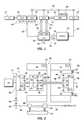
- FIG. 1is an electrical and mechanical schematic of a system architecture for a hybrid powertrain, according to an embodiment
- FIG. 2is an electrical and mechanical schematic of an electrically variable transmission that may be implemented into the hybrid powertrain shown in FIG. 1 , according to an embodiment
- FIG. 3is a flow diagram of a method of operating the hybrid powertrain, according to an embodiment.
- FIG. 1is a schematic of a system architecture for a hybrid powertrain 11 , according to an embodiment.
- the powertrain 11may include a hybrid control module (HCM) 19 that communicates with and provides commands to an electrically variable transmission (EVT) 10 , a battery pack module (BPM) 21 , an engine control module (ECM) 23 , and a system controller 43 .
- the HCM 19includes a pair of power inverters (not shown) and respective motor controllers (not shown) capable of receiving motor control commands and of controlling inverter states to provide motor drive or regeneration functionality.
- the invertersreceive current from DC lines and provide AC current to the respective motors of the EVT 10 over high voltage phase lines 29 and 31 .
- the invertersreceive AC current from corresponding motors over high voltage phase lines 29 and 31 and provide current to DC lines 27 .
- the net DC current provided to or from the invertersdetermines the charge or discharge operating mode of the BPM 21 .
- the motor controllerscontrol the inverters, and in this regard, may be microprocessor-based controllers comprising conventional elements, such as a microprocessor, read only memory (ROM), random access memory (RAM), electrically programmable read only memory (EPROM), high speed clock, analog to digital (A/D) and digital to analog (D/A) circuitry, input/output (I/O) circuitry, and devices and appropriate signal conditioning and buffer circuitry.
- the EVT 10communicates with the HCM 19 to receive commands therefrom to thereby provide a plurality of modes of operation to the hybrid powertrain 11 .
- the EVT 10has an input member 12 that may be a shaft, which may be directly driven by an engine 14 .
- a torque damper 16may be incorporated between an output member of the engine 14 and the input member 12 of the EVT 10 .
- the torque damper 16may receive commands from the EVT 10 to damp vibrations from the engine 14 .
- the torque damper 16may incorporate, or be employed in conjunction with, a torque transfer device (not shown) to permit selective engagement of the engine 14 with the EVT 10 .
- FIG. 2An embodiment of a schematic of the EVT 10 is shown in FIG. 2 .
- the EVT 10is illustrated as being capable of providing a plurality of modes of operation to the hybrid powertrain 11 via appropriate gearing combinations of one or more planetary gear subsets 24 , 26 , 28 .
- three gear subsets 24 , 26 , 28are included, and each is made up of a plurality of gears.
- the first planetary gear subset 24has an outer gear member 30 , which circumscribes an inner gear member 32 .
- a plurality of planetary gear members 34are rotatably mounted on a carrier 36 such that each planetary gear member 34 meshingly engages both the outer gear member 30 and the inner gear member 32 .
- the second planetary gear subset 26also has an outer gear member 38 , which circumscribes an inner gear member 40 .
- a plurality of planetary gear members 42are rotatably mounted on a carrier 44 such that each planetary gear 42 meshingly engages both the outer gear member 38 and the inner gear member 40 .
- the third planetary gear subset 28also has an outer gear member 46 , which circumscribes an inner gear member 48 .
- a plurality of planetary gear members 50are rotatably mounted on a carrier 52 such that each planetary gear 50 meshingly engages both the outer gear member 46 and the inner gear member 48 .
- the inner gear member 32 of the first planetary gear subset 24may be conjoined, via a hub plate gear 54 , to the outer gear member 38 of the second planetary gear subset 26 .
- the conjoined inner gear member 32 of the first planetary gear subset 24 and the outer gear member 38 of the second planetary gear subset 26are continuously connected to a first motor/generator 56 via a sleeve shaft 58 .
- the first motor/generator 56may also be referred to herein variously as motor A or MA and may be controlled by a motor control module (MCM) 57 .
- MCM 57may communicate with the HCM 19 and may receive commands therefrom.
- the carrier 36 of the first planetary gear subset 24may be conjoined via a shaft 60 , to the carrier 44 of the second planetary gear subset 26 . As such, the carriers 36 and 44 of the first and second planetary gear subsets 24 and 26 , respectively, are conjoined.
- the shaft 60is also selectively connected to the carrier 52 of the third planetary gear subset 28 via a torque transfer device 62 .
- the torque transfer device 62 or “second clutch C 2 ”may be employed to assist in the selection of the operational modes of the EVT 10 .
- the carrier 52 of the third planetary gear subset 28is connected directly to the transmission output member 64 .
- the output member 64may be connected to vehicular axles (not shown) that may, in turn, terminate in drive members (not shown).
- the drive membersmay be either front or rear wheels of a vehicle on which they are employed, or a drive gear of a track vehicle.
- the inner gear member 40 of the second planetary gear subset 26is connected to the inner gear member 48 of the third planetary gear subset 28 via a sleeve shaft 66 that circumscribes shaft 60 .
- the outer gear member 46 of the third planetary gear subset 28is selectively connected to ground, which may be a transmission housing 68 , through a torque transfer device 70 .
- the torque transfer device 70 or “first clutch C 1 ”may also be employed to assist in the selection of the operational modes of the EVT 10 .
- the sleeve shaft 66is also continuously connected to a second motor/generator 72 .
- the second motor/generator 72may also be referred to herein as motor B or MB.
- Motor Bmay be controlled by a motor control module (MCM) 73 .
- MCMmotor control module
- the MCM 73may communicate with the HCM 19 ( FIG. 1 ) and may receive commands therefrom. All the planetary gear subsets 24 , 26 , and 28 as well as motor A 56 and motor B 72 are coaxially oriented, as about the axially disposed shaft 60 .
- Both motors A and B 56 , 72may have an annular configuration and may circumscribe the three planetary gear subsets 24 , 26 , and 28 such that the planetary gear subsets 24 , 26 , and 28 are disposed radially inwardly of the motors A and B.
- a drive gear 80may be presented from the input member 12 to the outer gear member 30 of the first planetary gear subset 24 , and may, therefore, receive power from the engine 14 and/or motor A 56 or motor B 72 .
- the drive gear 80meshingly engages an idler gear 82 which, in turn, meshingly engages a transfer gear 84 that is secured to one end of a shaft 86 .
- the other end of the shaft 86may be secured to a transmission fluid pump 88 which is supplied transmission fluid from sump 37 , delivering high pressure fluid to regulator 39 which returns a portion of the fluid to sump 37 and provides regulated line pressure in line 41 .
- the output member 64receives power through two distinct gear trains within the EVT 10 .
- a first mode, or gear trainis selected when the first clutch C 1 is actuated in order to “ground” the outer gear member 46 of the third planetary gear subset 28 .
- a second mode, or gear trainis selected when the first clutch C 1 is released and the second clutch C 2 is simultaneously actuated to connect the shaft 60 to the carrier 52 of the third planetary gear subset 28 .
- an upper case designation MODE 1 or MODE 2or M 1 or M 2 , will generally be used.
- the EVT 10is further configured to provide a range of output speeds from relatively slow to relatively fast within each mode of operation. This combination of two modes with a slow to fast output speed range in each mode allows the EVT 10 to propel a vehicle from a stationary condition to highway speeds.
- a fixed-ratio statewherein both clutches C 1 and C 2 are simultaneously applied is available for efficient mechanical coupling of the input member to the output member through a fixed gear ratio.
- a neutral statewherein both clutches C 1 and C 2 are simultaneously released is available for mechanically decoupling the output member from the transmission.
- the EVT 10is capable of providing synchronized shifts between the modes wherein slip speed across both clutches C 1 and C 2 is substantially zero. Additional details regarding operation of the exemplary EVT can be found in commonly assigned U.S. Pat. No. 5,931,757, the contents of which are incorporated herein by reference.
- the EVT 10in addition to selectively receiving power from the engine 14 , the EVT 10 also receives power from an electric storage device such as one or more batteries in the BPM 21 .
- an electric storage devicesuch as one or more batteries in the BPM 21 .
- the BPM 21may be a high voltage DC device that may be coupled to the HCM 19 via DC lines 27 . Current may be transferable to or from the BPM 21 in accordance with whether the BPM 21 is being charged or discharged, as described above.
- a temperature sensor 20may be disposed on or proximate the BPM 21 . The temperature sensor 20 may sense temperature data relating to the BPM 21 and may communicate the data to the HCM 19 . The temperature data may be used by the HCM 19 to provide commands to limit power output from the batteries of the BPM 21 .
- the engine 14may be electronically controlled by the ECM 23 , which may in turn, receive commands from the HCM 19 , as illustrated in FIG. 1 .
- the ECM 23may comprise a microprocessor, ROM, RAM, EPROM, high speed clock, analog to digital (A/D) and digital to analog (D/A) circuitry, input/output circuitry and devices (I/O), and appropriate signal conditioning and buffer circuitry.
- the ECM 23may acquire data from a variety of sensors and may control a variety of actuators of the engine 14 over a plurality of discrete lines.
- the ECM 23may be in bi-directional interface with the engine 14 via an aggregate line 35 .
- the ECM 23may receive commands from the HCM 19 to supply fuel to a plurality of cylinders.
- the ECM 23may provide commands to appropriate actuators to supply fuel to (i) all of the cylinders, (ii) a portion of the cylinders (e.g., half), or (iii) none of the cylinders.
- the ECM 23may provide for well-known torque based controls for the engine 14 in response to a torque command (Te_cmd) provided by the EVT control system.
- the system controller 43may be configured to receive commands from the HCM 19 and to provide commands related to a variety of control and diagnostic functions for the EVT 10 and vehicle chassis.
- the system controller 43may be made up of a pair of microprocessor-based controllers, which may be referred to as a vehicle control module (VCM) 15 and a transmission control module (TCM) 17 .
- the controllersmay comprise microprocessors, ROM, RAM, EPROM, high speed clock, analog to digital (A/D) and digital to analog (D/A) circuitry, digital signal processor (DSP), and input/output circuitry and devices (I/O), and appropriate signal conditioning and buffer circuitry.
- the VCM 15 and TCM 17may provide, for example, engine torque commands, input speed control, and output torque control in coordination with regenerative braking, anti-lock braking and traction control.
- the system controller 43functions to directly acquire data from a variety of sensors and directly control a variety of actuators, respectively, of the EVT 10 over a plurality of discrete lines.
- the system controller 43may be in bi-directional interface with the EVT 10 via an aggregate line 33 and may receive frequency signals from rotation sensors for processing a speed into input member (Ni) and a speed into output member 64 (No) for use in the control of the EVT 10 .
- the system controller 43may also determine a torque command (Te_cmd) and provides the command to the ECM 23 .
- the torque command (Te_cmd)is representative of the EVT torque contribution desired from the engine as determined by the system controller 43 .
- the system controller 43may also determine a speed command (Ne_des) representative of the EVT input speed desired, which may also be a desired engine speed operating point.
- the various modules describedcommunicate via a controller area network (CAN) bus 25 .
- CANcontroller area network
- the CAN bus 25allows for communication of control parameters and commands between the various modules.
- the specific communication protocol utilizedwill be application specific.
- the HCM 19may receive data related to a temperature sensed from a battery pack of the BPM 21 .
- a first thresholdsuch as below a temperature at which the powertrain 11 may function without incurring damage to its components (e.g. below about 0° C.)
- the HCM 19may provide commands to other modules of the hybrid powertrain 11 that may override existing commands in order to limit power usage of those modules to thereby reduce power output from the batteries of the BPM 21 . Limiting the power usage of the modules in this way allows the hybrid powertrain 11 to continue operation under extremely cold conditions, such as in temperatures below about 0° C., without damaging the batteries, other components of the BPM 21 , or other components of the hybrid powertrain 11 .
- FIG. 3is a flow diagram of a method 300 of operating the HCT 19 , according to an embodiment.
- a determinationis made as to whether a temperature of the battery pack of the BPM 21 is below a first threshold, step 302 .
- the first thresholdmay be a temperature at which the powertrain 11 may operate that may cause damage to the batteries and other powertrain 11 components.
- the first thresholdmay be about 0° C. ⁇ 3° C. If the temperature is below the first threshold, the HCM 19 provides commands to the EVT 10 to limit its gear shifting commands between the first mode and the second mode (or MODE 1 and MODE 2 ), step 304 .
- the EVT 10selects which clutch to activate, step 306 .
- the EVT 10may select a first gear train in which the first clutch C 1 is actuated in order to “ground” the outer gear member 46 of the third planetary gear subset 28 , or the EVT 10 may select a second gear train in which the first clutch C 1 is released and the second clutch C 2 is simultaneously actuated to connect the shaft 60 to the carrier 52 of the third planetary gear subset 28 .
- second thresholdmay be a temperature that is about 0° C. ⁇ 3° C. In another embodiment, the second threshold may be about ⁇ 17° C. ⁇ 3° C. In still another embodiment, the second threshold may be equal to the first threshold. In still yet another embodiment, the second threshold may be a temperature that is above the first threshold. In still yet another embodiment, the second threshold may be a temperature that is less than the first threshold.
- commandsmay be provided by the HCM 19 to the EVT 10 to allow additional gear shifts to occur to thereby provide additional modes, step 310 .
- the EVT 10then causes both clutches to be activated, step 312 .
- the EVT 10may be instructed to provide commands to combine the first and the second modes with a slow to fast output speed range.
- the EVT 10may resume providing commands for a fixed-ratio gearing state wherein both clutches C 1 and C 2 are simultaneously applied, a neutral gearing state wherein both clutches C 1 and C 2 are simultaneously released is available for mechanically decoupling the output member from the transmission, and/or synchronized shifting between the modes wherein slip speed across both clutches C 1 and C 2 is substantially zero.
- the HCM 19may be configured to limit an amount of damping that may be provided by the torque damper 16 to the engine 14 .
- the HCM 19may provide a command to the EVT 10 to decrease an amount of damping supplied to the engine 14 by the torque damper 16 , when a determination is made that the temperature of the battery pack is below the first threshold.
- the HCM 19may instruct the EVT 10 not to supply power to the torque damper 16 .
- the HCM 19may be configured to gradually increase power to the torque damper 16 so that at least a portion of the vibration from the engine 14 may be damped. The gradual increase in power may be directly related to the increase in temperature, and in an embodiment, may follow a linear function.
- the HCM 19may be configured to supply a command to the ECM 23 to command a plurality of fuel injectors to inject fuel into all of the cylinders, when a determination is made that the temperature of the battery pack module is below the first threshold.
- the ECM 23may continue to provide commands to the fuel injectors to continue to inject fuel into all of the cylinders, if a determination is made that the temperature of the battery pack remains below the first threshold.
- the HCM 19may be configured to supply a command to the ECM 23 to allow the plurality of fuel injectors to inject fuel into at least a portion (e.g., half) of the cylinders or none of the cylinders, instead of all of the cylinders.
- the hybrid powertrainmay be adapted to operate efficiently in extremely low temperatures (e.g., temperatures below 0° C. ⁇ 3° C.) and may be used to prevent damage to battery packs that may be employed in conjunction with the powertrain when subjected to such temperatures.
Landscapes
- Engineering & Computer Science (AREA)
- Chemical & Material Sciences (AREA)
- Combustion & Propulsion (AREA)
- Transportation (AREA)
- Mechanical Engineering (AREA)
- Automation & Control Theory (AREA)
- Electric Propulsion And Braking For Vehicles (AREA)
- Hybrid Electric Vehicles (AREA)
Abstract
Description
Claims (16)
Priority Applications (3)
| Application Number | Priority Date | Filing Date | Title |
|---|---|---|---|
| US11/864,223US7766109B2 (en) | 2007-09-28 | 2007-09-28 | Hybrid powertrains and methods of operating |
| DE102008048462ADE102008048462A1 (en) | 2007-09-28 | 2008-09-25 | Hybrid powertrains and operating procedures |
| CN200810168735XACN101396960B (en) | 2007-09-28 | 2008-09-26 | Hybrid powertrains and methods of operating |
Applications Claiming Priority (1)
| Application Number | Priority Date | Filing Date | Title |
|---|---|---|---|
| US11/864,223US7766109B2 (en) | 2007-09-28 | 2007-09-28 | Hybrid powertrains and methods of operating |
Publications (2)
| Publication Number | Publication Date |
|---|---|
| US20090084618A1 US20090084618A1 (en) | 2009-04-02 |
| US7766109B2true US7766109B2 (en) | 2010-08-03 |
Family
ID=40459140
Family Applications (1)
| Application Number | Title | Priority Date | Filing Date |
|---|---|---|---|
| US11/864,223Expired - Fee RelatedUS7766109B2 (en) | 2007-09-28 | 2007-09-28 | Hybrid powertrains and methods of operating |
Country Status (3)
| Country | Link |
|---|---|
| US (1) | US7766109B2 (en) |
| CN (1) | CN101396960B (en) |
| DE (1) | DE102008048462A1 (en) |
Cited By (2)
| Publication number | Priority date | Publication date | Assignee | Title |
|---|---|---|---|---|
| US20090217907A1 (en)* | 2008-02-29 | 2009-09-03 | Brian Kenneth Garman | Power source braking system to prevent engine stalls |
| US11590842B1 (en)* | 2021-12-28 | 2023-02-28 | Dana Belgium N.V. | Transmission with power take-off |
Families Citing this family (23)
| Publication number | Priority date | Publication date | Assignee | Title |
|---|---|---|---|---|
| JP2008162491A (en)* | 2006-12-28 | 2008-07-17 | Toyota Motor Corp | Vehicle and control method thereof |
| TW201000349A (en)* | 2008-06-20 | 2010-01-01 | Sunyen Co Ltd | Digital input/output control device for electric vehicle |
| US8464690B2 (en) | 2008-07-11 | 2013-06-18 | Tula Technology, Inc. | Hybrid vehicle with cylinder deactivation |
| US8701628B2 (en) | 2008-07-11 | 2014-04-22 | Tula Technology, Inc. | Internal combustion engine control for improved fuel efficiency |
| US8892330B2 (en) | 2011-10-17 | 2014-11-18 | Tula Technology, Inc. | Hybrid vehicle with cylinder deactivation |
| BR112012013902A2 (en)* | 2009-12-08 | 2016-04-26 | Honda Motor Co Ltd | hybrid vehicle |
| US8560154B2 (en)* | 2010-09-14 | 2013-10-15 | GM Global Technology Operations LLC | Frequency splitting and independent limitation of vehicle torque control |
| KR101284330B1 (en)* | 2010-12-03 | 2013-07-17 | 기아자동차주식회사 | Shifting control method of hybrid vehicle |
| US8880258B2 (en) | 2011-10-17 | 2014-11-04 | Tula Technology, Inc. | Hybrid powertrain control |
| DE112012004795T8 (en)* | 2011-11-17 | 2014-11-20 | Tula Technology, Inc. | Hybrid powertrain control |
| JP6149772B2 (en)* | 2014-03-24 | 2017-06-21 | トヨタ自動車株式会社 | Hybrid vehicle |
| US10578037B2 (en) | 2015-01-12 | 2020-03-03 | Tula Technology, Inc. | Adaptive torque mitigation by micro-hybrid system |
| CN107110039B (en) | 2015-01-12 | 2019-03-01 | 图拉技术公司 | Noise, vibration and harshness reduction in skip-fire engine control systems |
| US10060368B2 (en) | 2015-01-12 | 2018-08-28 | Tula Technology, Inc. | Engine torque smoothing |
| US10344692B2 (en) | 2015-01-12 | 2019-07-09 | Tula Technology, Inc. | Adaptive torque mitigation by micro-hybrid system |
| US10196995B2 (en) | 2015-01-12 | 2019-02-05 | Tula Technology, Inc. | Engine torque smoothing |
| US9702306B2 (en)* | 2015-10-13 | 2017-07-11 | Tecogen Inc. | Internal combustion engine controller |
| JP6831193B2 (en) | 2016-08-26 | 2021-02-17 | トヨタ自動車株式会社 | Hybrid vehicle control device |
| US10954877B2 (en) | 2017-03-13 | 2021-03-23 | Tula Technology, Inc. | Adaptive torque mitigation by micro-hybrid system |
| JP6812903B2 (en)* | 2017-05-26 | 2021-01-13 | トヨタ自動車株式会社 | Hybrid vehicle |
| US11840248B2 (en)* | 2019-09-05 | 2023-12-12 | Ford Global Technologies, Llc | Method and system for categorizing powertrain torque requests |
| US11555461B2 (en) | 2020-10-20 | 2023-01-17 | Tula Technology, Inc. | Noise, vibration and harshness reduction in a skip fire engine control system |
| US11936327B2 (en) | 2021-06-23 | 2024-03-19 | Tecogen Inc. | Hybrid power system with electric generator and auxiliary power source |
Citations (9)
| Publication number | Priority date | Publication date | Assignee | Title |
|---|---|---|---|---|
| US5806617A (en)* | 1995-04-20 | 1998-09-15 | Kabushikikaisha Equos Research | Hybrid vehicle |
| US6428444B1 (en)* | 1999-09-06 | 2002-08-06 | Toyota Jidosha Kabushiki Kaisha | Apparatus for controlling a vehicle and a method of controlling the vehicle |
| US6480767B2 (en)* | 2000-09-22 | 2002-11-12 | Nissan Motor Co., Ltd. | Control system for hybrid vehicle |
| US6621244B1 (en)* | 1999-08-05 | 2003-09-16 | Honda Giken Kogyo Kabushiki Kaisha | Control apparatus for hybrid vehicle |
| US6870336B2 (en)* | 2001-09-10 | 2005-03-22 | Honda Giken Kogyo Kabushiki Kaisha | Vehicle driving apparatus |
| US20050139400A1 (en)* | 2001-05-03 | 2005-06-30 | Ford Motor Company | Control algorithm for hybrid electric vehicle |
| US7074157B2 (en)* | 2003-07-04 | 2006-07-11 | Honda Motor Co., Ltd. | Control apparatus for hybrid vehicle |
| US7090612B2 (en)* | 2002-12-25 | 2006-08-15 | Toyota Jidosha Kabushiki Kaisha | Control device of hybrid drive unit and control method thereof |
| US7223202B2 (en)* | 2004-03-22 | 2007-05-29 | General Motors Corporation | Hydraulic circuit for torsional damper assembly of an electrically variable transmission |
Family Cites Families (1)
| Publication number | Priority date | Publication date | Assignee | Title |
|---|---|---|---|---|
| US5931757A (en) | 1998-06-24 | 1999-08-03 | General Motors Corporation | Two-mode, compound-split electro-mechanical vehicular transmission |
- 2007
- 2007-09-28USUS11/864,223patent/US7766109B2/ennot_activeExpired - Fee Related
- 2008
- 2008-09-25DEDE102008048462Apatent/DE102008048462A1/ennot_activeCeased
- 2008-09-26CNCN200810168735XApatent/CN101396960B/ennot_activeExpired - Fee Related
Patent Citations (9)
| Publication number | Priority date | Publication date | Assignee | Title |
|---|---|---|---|---|
| US5806617A (en)* | 1995-04-20 | 1998-09-15 | Kabushikikaisha Equos Research | Hybrid vehicle |
| US6621244B1 (en)* | 1999-08-05 | 2003-09-16 | Honda Giken Kogyo Kabushiki Kaisha | Control apparatus for hybrid vehicle |
| US6428444B1 (en)* | 1999-09-06 | 2002-08-06 | Toyota Jidosha Kabushiki Kaisha | Apparatus for controlling a vehicle and a method of controlling the vehicle |
| US6480767B2 (en)* | 2000-09-22 | 2002-11-12 | Nissan Motor Co., Ltd. | Control system for hybrid vehicle |
| US20050139400A1 (en)* | 2001-05-03 | 2005-06-30 | Ford Motor Company | Control algorithm for hybrid electric vehicle |
| US6870336B2 (en)* | 2001-09-10 | 2005-03-22 | Honda Giken Kogyo Kabushiki Kaisha | Vehicle driving apparatus |
| US7090612B2 (en)* | 2002-12-25 | 2006-08-15 | Toyota Jidosha Kabushiki Kaisha | Control device of hybrid drive unit and control method thereof |
| US7074157B2 (en)* | 2003-07-04 | 2006-07-11 | Honda Motor Co., Ltd. | Control apparatus for hybrid vehicle |
| US7223202B2 (en)* | 2004-03-22 | 2007-05-29 | General Motors Corporation | Hydraulic circuit for torsional damper assembly of an electrically variable transmission |
Cited By (3)
| Publication number | Priority date | Publication date | Assignee | Title |
|---|---|---|---|---|
| US20090217907A1 (en)* | 2008-02-29 | 2009-09-03 | Brian Kenneth Garman | Power source braking system to prevent engine stalls |
| US7926464B2 (en)* | 2008-02-29 | 2011-04-19 | Caterpillar Inc. | Power source braking system to prevent engine stalls |
| US11590842B1 (en)* | 2021-12-28 | 2023-02-28 | Dana Belgium N.V. | Transmission with power take-off |
Also Published As
| Publication number | Publication date |
|---|---|
| CN101396960A (en) | 2009-04-01 |
| US20090084618A1 (en) | 2009-04-02 |
| CN101396960B (en) | 2012-06-20 |
| DE102008048462A1 (en) | 2009-04-23 |
Similar Documents
| Publication | Publication Date | Title |
|---|---|---|
| US7766109B2 (en) | Hybrid powertrains and methods of operating | |
| US7130734B2 (en) | Two clutch fixed-ratio exit control for multi-mode hybrid drive | |
| US7865287B2 (en) | Method and apparatus for controlling power flow in a hybrid powertrain system | |
| US7987934B2 (en) | Method for controlling engine speed in a hybrid electric vehicle | |
| US7449891B2 (en) | Managing service life of a battery | |
| US7010406B2 (en) | Shift inhibit control for multi-mode hybrid drive | |
| US10150468B2 (en) | Step-ratio transmission control for a hybrid vehicle | |
| US7127337B2 (en) | Silent operating mode for reducing emissions of a hybrid electric vehicle | |
| US6832148B1 (en) | Automatic engine stop and restart mode for reducing emissions of a hybrid electric vehicle | |
| US7222013B2 (en) | Throttle phase out control | |
| US7556120B2 (en) | Method and apparatus to control hydraulic pressure in an electro-mechanical transmission | |
| US6946818B2 (en) | Method of determining battery power limits for an energy storage system of a hybrid electric vehicle | |
| US7474012B2 (en) | Engine starting control apparatus for hybrid vehicle | |
| US8007402B2 (en) | Control apparatus for hybrid vehicle drive system | |
| US7219000B2 (en) | Speed control for an electrically variable transmission | |
| US7503870B2 (en) | Control apparatus for vehicular drive system | |
| US7927250B2 (en) | Control apparatus for vehicular power transmitting system | |
| US7610892B2 (en) | System and method for starting a vehicle | |
| US20050080539A1 (en) | Method for determining preferred input operating points for a vehicle transmission | |
| US20070149348A1 (en) | Vehicle propulsion system | |
| US7909582B2 (en) | Vehicular oil pump control apparatus | |
| CN101446343A (en) | Method for controlling a powertrain system based upon energy storage device temperature | |
| CN102256853A (en) | Control device for power transmission device for vehicle | |
| JP2010083361A (en) | Controller of power transmission for vehicle | |
| CN206231219U (en) | Double synchronizer clutch and planetary gear coupling double-motor power system |
Legal Events
| Date | Code | Title | Description |
|---|---|---|---|
| AS | Assignment | Owner name:GM GLOBAL TECHNOLOGY OPERATIONS, INC., MICHIGAN Free format text:ASSIGNMENT OF ASSIGNORS INTEREST;ASSIGNORS:THOMPSON, SCOTT;SYDENSTRICKER, JAMES;REEL/FRAME:019915/0237 Effective date:20070924 | |
| AS | Assignment | Owner name:UNITED STATES DEPARTMENT OF THE TREASURY,DISTRICT Free format text:SECURITY AGREEMENT;ASSIGNOR:GM GLOBAL TECHNOLOGY OPERATIONS, INC.;REEL/FRAME:022201/0405 Effective date:20081231 Owner name:UNITED STATES DEPARTMENT OF THE TREASURY, DISTRICT Free format text:SECURITY AGREEMENT;ASSIGNOR:GM GLOBAL TECHNOLOGY OPERATIONS, INC.;REEL/FRAME:022201/0405 Effective date:20081231 | |
| AS | Assignment | Owner name:CITICORP USA, INC. AS AGENT FOR BANK PRIORITY SECU Free format text:SECURITY AGREEMENT;ASSIGNOR:GM GLOBAL TECHNOLOGY OPERATIONS, INC.;REEL/FRAME:022554/0479 Effective date:20090409 Owner name:CITICORP USA, INC. AS AGENT FOR HEDGE PRIORITY SEC Free format text:SECURITY AGREEMENT;ASSIGNOR:GM GLOBAL TECHNOLOGY OPERATIONS, INC.;REEL/FRAME:022554/0479 Effective date:20090409 | |
| AS | Assignment | Owner name:GM GLOBAL TECHNOLOGY OPERATIONS, INC., MICHIGAN Free format text:RELEASE BY SECURED PARTY;ASSIGNOR:UNITED STATES DEPARTMENT OF THE TREASURY;REEL/FRAME:023124/0670 Effective date:20090709 Owner name:GM GLOBAL TECHNOLOGY OPERATIONS, INC.,MICHIGAN Free format text:RELEASE BY SECURED PARTY;ASSIGNOR:UNITED STATES DEPARTMENT OF THE TREASURY;REEL/FRAME:023124/0670 Effective date:20090709 | |
| AS | Assignment | Owner name:GM GLOBAL TECHNOLOGY OPERATIONS, INC., MICHIGAN Free format text:RELEASE BY SECURED PARTY;ASSIGNORS:CITICORP USA, INC. AS AGENT FOR BANK PRIORITY SECURED PARTIES;CITICORP USA, INC. AS AGENT FOR HEDGE PRIORITY SECURED PARTIES;REEL/FRAME:023155/0880 Effective date:20090814 Owner name:GM GLOBAL TECHNOLOGY OPERATIONS, INC.,MICHIGAN Free format text:RELEASE BY SECURED PARTY;ASSIGNORS:CITICORP USA, INC. AS AGENT FOR BANK PRIORITY SECURED PARTIES;CITICORP USA, INC. AS AGENT FOR HEDGE PRIORITY SECURED PARTIES;REEL/FRAME:023155/0880 Effective date:20090814 | |
| AS | Assignment | Owner name:UNITED STATES DEPARTMENT OF THE TREASURY, DISTRICT Free format text:SECURITY AGREEMENT;ASSIGNOR:GM GLOBAL TECHNOLOGY OPERATIONS, INC.;REEL/FRAME:023156/0215 Effective date:20090710 Owner name:UNITED STATES DEPARTMENT OF THE TREASURY,DISTRICT Free format text:SECURITY AGREEMENT;ASSIGNOR:GM GLOBAL TECHNOLOGY OPERATIONS, INC.;REEL/FRAME:023156/0215 Effective date:20090710 | |
| AS | Assignment | Owner name:UAW RETIREE MEDICAL BENEFITS TRUST, MICHIGAN Free format text:SECURITY AGREEMENT;ASSIGNOR:GM GLOBAL TECHNOLOGY OPERATIONS, INC.;REEL/FRAME:023162/0187 Effective date:20090710 Owner name:UAW RETIREE MEDICAL BENEFITS TRUST,MICHIGAN Free format text:SECURITY AGREEMENT;ASSIGNOR:GM GLOBAL TECHNOLOGY OPERATIONS, INC.;REEL/FRAME:023162/0187 Effective date:20090710 | |
| FEPP | Fee payment procedure | Free format text:PAYOR NUMBER ASSIGNED (ORIGINAL EVENT CODE: ASPN); ENTITY STATUS OF PATENT OWNER: LARGE ENTITY | |
| STCF | Information on status: patent grant | Free format text:PATENTED CASE | |
| AS | Assignment | Owner name:GM GLOBAL TECHNOLOGY OPERATIONS, INC., MICHIGAN Free format text:RELEASE BY SECURED PARTY;ASSIGNOR:UNITED STATES DEPARTMENT OF THE TREASURY;REEL/FRAME:025245/0780 Effective date:20100420 | |
| AS | Assignment | Owner name:GM GLOBAL TECHNOLOGY OPERATIONS, INC., MICHIGAN Free format text:RELEASE BY SECURED PARTY;ASSIGNOR:UAW RETIREE MEDICAL BENEFITS TRUST;REEL/FRAME:025314/0946 Effective date:20101026 | |
| AS | Assignment | Owner name:WILMINGTON TRUST COMPANY, DELAWARE Free format text:SECURITY AGREEMENT;ASSIGNOR:GM GLOBAL TECHNOLOGY OPERATIONS, INC.;REEL/FRAME:025324/0057 Effective date:20101027 | |
| AS | Assignment | Owner name:GM GLOBAL TECHNOLOGY OPERATIONS LLC, MICHIGAN Free format text:CHANGE OF NAME;ASSIGNOR:GM GLOBAL TECHNOLOGY OPERATIONS, INC.;REEL/FRAME:025781/0035 Effective date:20101202 | |
| FPAY | Fee payment | Year of fee payment:4 | |
| AS | Assignment | Owner name:GM GLOBAL TECHNOLOGY OPERATIONS LLC, MICHIGAN Free format text:RELEASE BY SECURED PARTY;ASSIGNOR:WILMINGTON TRUST COMPANY;REEL/FRAME:034185/0587 Effective date:20141017 | |
| MAFP | Maintenance fee payment | Free format text:PAYMENT OF MAINTENANCE FEE, 8TH YEAR, LARGE ENTITY (ORIGINAL EVENT CODE: M1552) Year of fee payment:8 | |
| FEPP | Fee payment procedure | Free format text:MAINTENANCE FEE REMINDER MAILED (ORIGINAL EVENT CODE: REM.); ENTITY STATUS OF PATENT OWNER: LARGE ENTITY | |
| LAPS | Lapse for failure to pay maintenance fees | Free format text:PATENT EXPIRED FOR FAILURE TO PAY MAINTENANCE FEES (ORIGINAL EVENT CODE: EXP.); ENTITY STATUS OF PATENT OWNER: LARGE ENTITY | |
| STCH | Information on status: patent discontinuation | Free format text:PATENT EXPIRED DUE TO NONPAYMENT OF MAINTENANCE FEES UNDER 37 CFR 1.362 | |
| FP | Lapsed due to failure to pay maintenance fee | Effective date:20220803 |