US7766106B2 - Powered wheelchair configurations and related methods of use - Google Patents
Powered wheelchair configurations and related methods of useDownload PDFInfo
- Publication number
- US7766106B2 US7766106B2US11/486,638US48663806AUS7766106B2US 7766106 B2US7766106 B2US 7766106B2US 48663806 AUS48663806 AUS 48663806AUS 7766106 B2US7766106 B2US 7766106B2
- Authority
- US
- United States
- Prior art keywords
- wheelchair
- drive
- axis
- wheel
- frame
- Prior art date
- Legal status (The legal status is an assumption and is not a legal conclusion. Google has not performed a legal analysis and makes no representation as to the accuracy of the status listed.)
- Active, expires
Links
- 238000000034methodMethods0.000titleclaimsdescription11
- 235000004443Ricinus communisNutrition0.000claimsdescription9
- 230000001174ascending effectEffects0.000claimsdescription9
- 230000000712assemblyEffects0.000claimsdescription7
- 238000000429assemblyMethods0.000claimsdescription7
- 230000009467reductionEffects0.000claimsdescription7
- 239000000725suspensionSubstances0.000claimsdescription6
- 238000006243chemical reactionMethods0.000claimsdescription3
- 240000000528Ricinus communisSpecies0.000claims1
- 239000011295pitchSubstances0.000claims1
- 230000007246mechanismEffects0.000description8
- 230000004044responseEffects0.000description5
- 230000001133accelerationEffects0.000description4
- 230000008901benefitEffects0.000description4
- 230000009194climbingEffects0.000description3
- 230000005484gravityEffects0.000description2
- 0*C1NC1*=CChemical compound*C1NC1*=C0.000description1
- 230000009286beneficial effectEffects0.000description1
- 230000008859changeEffects0.000description1
- 230000008878couplingEffects0.000description1
- 238000010168coupling processMethods0.000description1
- 238000005859coupling reactionMethods0.000description1
- 230000003292diminished effectEffects0.000description1
- 238000005516engineering processMethods0.000description1
- 230000002708enhancing effectEffects0.000description1
- 230000006872improvementEffects0.000description1
- 238000003780insertionMethods0.000description1
- 230000037431insertionEffects0.000description1
- 230000008569processEffects0.000description1
- 230000007704transitionEffects0.000description1
Images


Classifications
- A—HUMAN NECESSITIES
- A61—MEDICAL OR VETERINARY SCIENCE; HYGIENE
- A61G—TRANSPORT, PERSONAL CONVEYANCES, OR ACCOMMODATION SPECIALLY ADAPTED FOR PATIENTS OR DISABLED PERSONS; OPERATING TABLES OR CHAIRS; CHAIRS FOR DENTISTRY; FUNERAL DEVICES
- A61G5/00—Chairs or personal conveyances specially adapted for patients or disabled persons, e.g. wheelchairs
- A61G5/04—Chairs or personal conveyances specially adapted for patients or disabled persons, e.g. wheelchairs motor-driven
- A61G5/041—Chairs or personal conveyances specially adapted for patients or disabled persons, e.g. wheelchairs motor-driven having a specific drive-type
- A61G5/042—Front wheel drive
- A—HUMAN NECESSITIES
- A61—MEDICAL OR VETERINARY SCIENCE; HYGIENE
- A61G—TRANSPORT, PERSONAL CONVEYANCES, OR ACCOMMODATION SPECIALLY ADAPTED FOR PATIENTS OR DISABLED PERSONS; OPERATING TABLES OR CHAIRS; CHAIRS FOR DENTISTRY; FUNERAL DEVICES
- A61G5/00—Chairs or personal conveyances specially adapted for patients or disabled persons, e.g. wheelchairs
- A61G5/06—Chairs or personal conveyances specially adapted for patients or disabled persons, e.g. wheelchairs with obstacle mounting facilities, e.g. for climbing stairs, kerbs or steps
- A61G5/061—Chairs or personal conveyances specially adapted for patients or disabled persons, e.g. wheelchairs with obstacle mounting facilities, e.g. for climbing stairs, kerbs or steps for climbing stairs
- A—HUMAN NECESSITIES
- A61—MEDICAL OR VETERINARY SCIENCE; HYGIENE
- A61G—TRANSPORT, PERSONAL CONVEYANCES, OR ACCOMMODATION SPECIALLY ADAPTED FOR PATIENTS OR DISABLED PERSONS; OPERATING TABLES OR CHAIRS; CHAIRS FOR DENTISTRY; FUNERAL DEVICES
- A61G5/00—Chairs or personal conveyances specially adapted for patients or disabled persons, e.g. wheelchairs
- A61G5/04—Chairs or personal conveyances specially adapted for patients or disabled persons, e.g. wheelchairs motor-driven
- A61G5/041—Chairs or personal conveyances specially adapted for patients or disabled persons, e.g. wheelchairs motor-driven having a specific drive-type
- A61G5/043—Mid wheel drive
- A—HUMAN NECESSITIES
- A61—MEDICAL OR VETERINARY SCIENCE; HYGIENE
- A61G—TRANSPORT, PERSONAL CONVEYANCES, OR ACCOMMODATION SPECIALLY ADAPTED FOR PATIENTS OR DISABLED PERSONS; OPERATING TABLES OR CHAIRS; CHAIRS FOR DENTISTRY; FUNERAL DEVICES
- A61G5/00—Chairs or personal conveyances specially adapted for patients or disabled persons, e.g. wheelchairs
- A61G5/06—Chairs or personal conveyances specially adapted for patients or disabled persons, e.g. wheelchairs with obstacle mounting facilities, e.g. for climbing stairs, kerbs or steps
- A—HUMAN NECESSITIES
- A61—MEDICAL OR VETERINARY SCIENCE; HYGIENE
- A61G—TRANSPORT, PERSONAL CONVEYANCES, OR ACCOMMODATION SPECIALLY ADAPTED FOR PATIENTS OR DISABLED PERSONS; OPERATING TABLES OR CHAIRS; CHAIRS FOR DENTISTRY; FUNERAL DEVICES
- A61G5/00—Chairs or personal conveyances specially adapted for patients or disabled persons, e.g. wheelchairs
- A61G5/10—Parts, details or accessories
- A61G5/1078—Parts, details or accessories with shock absorbers or other suspension arrangements between wheels and frame
- A—HUMAN NECESSITIES
- A61—MEDICAL OR VETERINARY SCIENCE; HYGIENE
- A61G—TRANSPORT, PERSONAL CONVEYANCES, OR ACCOMMODATION SPECIALLY ADAPTED FOR PATIENTS OR DISABLED PERSONS; OPERATING TABLES OR CHAIRS; CHAIRS FOR DENTISTRY; FUNERAL DEVICES
- A61G5/00—Chairs or personal conveyances specially adapted for patients or disabled persons, e.g. wheelchairs
- A61G5/10—Parts, details or accessories
- A61G5/1089—Anti-tip devices
- B—PERFORMING OPERATIONS; TRANSPORTING
- B60—VEHICLES IN GENERAL
- B60K—ARRANGEMENT OR MOUNTING OF PROPULSION UNITS OR OF TRANSMISSIONS IN VEHICLES; ARRANGEMENT OR MOUNTING OF PLURAL DIVERSE PRIME-MOVERS IN VEHICLES; AUXILIARY DRIVES FOR VEHICLES; INSTRUMENTATION OR DASHBOARDS FOR VEHICLES; ARRANGEMENTS IN CONNECTION WITH COOLING, AIR INTAKE, GAS EXHAUST OR FUEL SUPPLY OF PROPULSION UNITS IN VEHICLES
- B60K1/00—Arrangement or mounting of electrical propulsion units
- B60K1/02—Arrangement or mounting of electrical propulsion units comprising more than one electric motor
- B—PERFORMING OPERATIONS; TRANSPORTING
- B60—VEHICLES IN GENERAL
- B60K—ARRANGEMENT OR MOUNTING OF PROPULSION UNITS OR OF TRANSMISSIONS IN VEHICLES; ARRANGEMENT OR MOUNTING OF PLURAL DIVERSE PRIME-MOVERS IN VEHICLES; AUXILIARY DRIVES FOR VEHICLES; INSTRUMENTATION OR DASHBOARDS FOR VEHICLES; ARRANGEMENTS IN CONNECTION WITH COOLING, AIR INTAKE, GAS EXHAUST OR FUEL SUPPLY OF PROPULSION UNITS IN VEHICLES
- B60K1/00—Arrangement or mounting of electrical propulsion units
- B60K1/04—Arrangement or mounting of electrical propulsion units of the electric storage means for propulsion
- B—PERFORMING OPERATIONS; TRANSPORTING
- B62—LAND VEHICLES FOR TRAVELLING OTHERWISE THAN ON RAILS
- B62D—MOTOR VEHICLES; TRAILERS
- B62D61/00—Motor vehicles or trailers, characterised by the arrangement or number of wheels, not otherwise provided for, e.g. four wheels in diamond pattern
- B62D61/10—Motor vehicles or trailers, characterised by the arrangement or number of wheels, not otherwise provided for, e.g. four wheels in diamond pattern with more than four wheels
- A—HUMAN NECESSITIES
- A61—MEDICAL OR VETERINARY SCIENCE; HYGIENE
- A61G—TRANSPORT, PERSONAL CONVEYANCES, OR ACCOMMODATION SPECIALLY ADAPTED FOR PATIENTS OR DISABLED PERSONS; OPERATING TABLES OR CHAIRS; CHAIRS FOR DENTISTRY; FUNERAL DEVICES
- A61G5/00—Chairs or personal conveyances specially adapted for patients or disabled persons, e.g. wheelchairs
- A61G5/10—Parts, details or accessories
- A61G5/14—Standing-up or sitting-down aids
- B—PERFORMING OPERATIONS; TRANSPORTING
- B60—VEHICLES IN GENERAL
- B60Y—INDEXING SCHEME RELATING TO ASPECTS CROSS-CUTTING VEHICLE TECHNOLOGY
- B60Y2200/00—Type of vehicle
- B60Y2200/80—Other vehicles not covered by groups B60Y2200/10 - B60Y2200/60
- B60Y2200/84—Wheelchairs
- Y—GENERAL TAGGING OF NEW TECHNOLOGICAL DEVELOPMENTS; GENERAL TAGGING OF CROSS-SECTIONAL TECHNOLOGIES SPANNING OVER SEVERAL SECTIONS OF THE IPC; TECHNICAL SUBJECTS COVERED BY FORMER USPC CROSS-REFERENCE ART COLLECTIONS [XRACs] AND DIGESTS
- Y10—TECHNICAL SUBJECTS COVERED BY FORMER USPC
- Y10S—TECHNICAL SUBJECTS COVERED BY FORMER USPC CROSS-REFERENCE ART COLLECTIONS [XRACs] AND DIGESTS
- Y10S180/00—Motor vehicles
- Y10S180/907—Motorized wheelchairs
- Y—GENERAL TAGGING OF NEW TECHNOLOGICAL DEVELOPMENTS; GENERAL TAGGING OF CROSS-SECTIONAL TECHNOLOGIES SPANNING OVER SEVERAL SECTIONS OF THE IPC; TECHNICAL SUBJECTS COVERED BY FORMER USPC CROSS-REFERENCE ART COLLECTIONS [XRACs] AND DIGESTS
- Y10—TECHNICAL SUBJECTS COVERED BY FORMER USPC
- Y10S—TECHNICAL SUBJECTS COVERED BY FORMER USPC CROSS-REFERENCE ART COLLECTIONS [XRACs] AND DIGESTS
- Y10S297/00—Chairs and seats
- Y10S297/04—Wheelchair
Definitions
- the present inventionrelates to powered wheelchairs, and more specifically to wheelchair configurations that are capable of assisting in curb-climbing.
- Powered wheelchairsoften have six wheels including a pair of center wheels, a pair of rear wheels, and a pair of front wheels.
- one pair of wheelsis driven by, and directly connected to, a drive.
- the front wheelsmay be suspended above the ground plane on which the wheelchair rests or in contact with the ground.
- wheels that are spaced apart from the ground surface, or configured to only lightly contact the ground surfaceare fixed except for the capability of turning about their axes of rotation; such wheels are referred to herein as “fixed wheels.”
- Wheels that are configured to ride on the ground surface during normal operationtypically have the capability to swivel about a vertical axis; such wheels are referred to herein as “casters.”
- Wheelchairs that employ fixed wheelsoften employ springs to suspend the fixed wheels above the ground at the end of forward extending arms.
- the fixed wheelsare the first part of the wheelchair that contact a curb, and the fixed wheels are often configured to ride over a curb.
- Wheelchairs that employ castersoften are disposed on forward-extending arms that are coupled to the frame at a pivot.
- Some wheelchairssuch as those employing an Active-TrackTM suspension, available on some powered wheelchairs from Pride Mobility Products Corporation, have pivoting front caster arms that raise or are upwardly biased in response to wheelchair acceleration or motor torque to enhance the capability of the wheelchair to climb curbs.
- Pivotable front caster armstypically employ biasing springs to provide a downward force that is balanced against the drive's capability to raise the casters for ascending a curb and that urges the casters downward to contact the lower ground surface while descending a curb.
- Wheelchairstypically have a frame onto which loads from the passenger and the wheelchair's batteries are applied.
- loads from the batteries and passengertypically are applied between the axis of rotation of the center wheels and the rear casters, especially where the center wheels are the drive wheels.
- the batteriesare located such that the center of gravity of the batteries is near, but rearward of, the center drive wheels or in general near the center of the wheelchair.
- the drive for each drive wheeltypically includes a longitudinally oriented (that is, oriented parallel to the axis of straight-ahead movement of the wheelchair) motor and a right-angle gearbox.
- An exception to such drive and battery configurationis shown in U.S. Pat. No. 5,964,473 (“Degonda”), which discloses a transversely oriented motor that splits the battery compartment.
- a wheelchairincludes a frame; a pair of drive wheels and at least one rear wheel; a pair of drives operatively coupled to the drive wheels such that each one of the drives includes a motor and a gearbox; a pair of forward-extending, front arms rigidly coupled to the drives such that each one of the drives-and-front arm structures is pivotally coupled to the frame only at a single pivot axis; and a pair of front wheels rotatably coupled the front arm.
- a centerline of the pivot axishas a vertical height that is approximately the same or less than the vertical height of an axis of rotation of the front wheel. Accordingly, the motor torque is capable of biasing the front wheels when encountering or ascending a curb, when accelerating, and when decelerating.
- the wheelchair driveincludes a drive mount, which preferably is an upright mounting plate, to which the gearbox is rigidly coupled.
- the drive mountis coupled to the frame at the pivot axis.
- the motorspreferably are transversely mounted and their batteries are located to the rear of the motors.
- An articulating beamis generally located generally behind the batteries.
- the pivot axispreferably is spaced apart from the front wheel axis by a horizontal dimension that is between about 40% and about 65% of the horizontal dimension between the drive wheel axis and the front castor axis, more preferably between about 45% and about 60%, more preferably, approximately 54% of the horizontal dimension between the drive wheel axis and the front castor axis.
- a method of using this wheelchair configurationincludes positioning the wheelchair such that the front wheels are in contact with or in close proximity to an obstacle that has a height measured from a support surface that is approximately equal to or less than the height of the front wheel axis of rotation; and urging the wheelchair forward to enable the front wheels to ascend the obstacle.
- a wheelchairincludes a frame; a pair of opposing drives, each including a substantially-transversely mounted motor and gearbox; a pair of drive wheels each coupled to a corresponding one of the drives; and a chair assembly supported on the frame and being moveably coupled thereto such that the chair is forwardly moveable to enhance access to a power supply portion of the wheelchair without fully removing the chair from the frame.
- the power supply portionconstitutes batteries that are located rearward of the chair support and rearward of the motors.
- the seatis hinged or slideable.
- a wheelchairincludes a frame; a pair of opposing drive wheels; a pair of pivoting assemblies associated with the drive wheels and including a drive assembly and a front arm assembly.
- Each drive assembly(i) includes a motor and gearbox that are transversely mounted relative to the frame, (ii) is operatively coupled to one of the drive wheels, and (iii) is pivotally connected to the frame.
- Each front arm assemblyincludes a front wheel rotatably coupled to the front arm, and the front arm assembly is rigidly coupled to the drive assembly. Accordingly, the drive assembly and front arm assembly pivot in unison about the pivotal connection upon encountering an obstacle.
- a pivot axis of the pivotal connection between the drive assembly and the framehas a vertical height that is approximately the same or less than the vertical height of an axis of rotation of the front wheel.
- the motor and single reduction gearbox assemblyhas a longitudinal axis that is transverse relative to the frame, and the drive assembly includes a mount to which the gearbox is affixed such that the mount includes a surface to which the front arm is rigidly affixed.
- the battery compartmentmay be located rearward of the drive and an articulating transverse beam, located rearward of the battery, may include a pair of rear idler wheels.
- a wheelchairincludes a frame; a seat coupled to the frame; a pair of opposing drive wheels and at least one rear wheel.
- Each side of the wheelchairincludes: a drive including a motor and a gearbox that are transversely mounted, such the drive is operatively coupled to a drive wheel; and a forward-extending, front arm rigidly coupled to the drive such that each one of the drive and front arm structures is pivotally coupled to the frame only at a single pivot axis.
- the wheelchairalso includes a front wheel located at a forward end of the front arm; a pivoting transverse beam located rearward of the drive wheels and having a pair of rear idler wheels coupled to opposing ends thereof; and at least one battery assembly that is accessible from rearward of the drive wheels.
- the gearboxis a single reduction gearbox and the front wheel is rotatably coupled the front arm, and a centerline of the pivot axis has a height that is approximately the same or less than the vertical height of an axis of rotation of the front wheel.
- the pivot on which the transverse beam pivotsis substantially horizontal and located rearward of the battery assembly such that the battery assembly is accessible via the back-center of the wheelchair.
- a wheelchairincludes a frame; a seat coupled to the frame; a pair of opposing drive wheels and at least one rear wheel.
- Each side of the wheelchairincludes a drive including a motor and a gearbox that are transversely mounted, wherein the drive is operatively coupled to a drive wheel; a forward-extending, front arm operatively coupled to the drive whereby motor torque may bias the front arm, wherein the front arm coupled to the frame at a pivot axis; and a front wheel rotatably coupled the front arm such that a centerline of the pivot axis (i) has a height that is approximately the same or less than the vertical height of an axis of rotation of the front wheel and (ii) is horizontally spaced apart from the axis of rotation of the front wheel by no more than about 65% of the horizontal distance between the axis of rotation of the front wheel and the drive wheel axis.
- the centerline of the pivot axisis horizontally spaced apart from the axis of rotation of the front wheel more preferably by no more than about 50% of the horizontal distance between the axis of rotation of the front wheel and the drive wheel axis, more preferably no more than about 40%, and even more preferably no more than about 33% of the horizontal distance between the axis of rotation of the front wheel and the drive wheel axis.
- the wheelchairincludes a pivoting transverse beam that is located rearward of the drive wheels, and rearward of the batteries, and that has a pair of rear idler wheels coupled to opposing ends thereof.
- a wheelchairincludes a frame; a seat coupled to the frame; a pair of opposing drive wheels; and at least one rear wheel.
- Each side of the wheelchairincludes: a drive including a motor and a gearbox that are transversely mounted such that the drive is operatively coupled to a drive wheel; a forward-extending, front arm operatively coupled to the drive whereby motor torque may bias the front arm and such that the front arm is coupled to the frame at a pivot axis; and a front wheel rotatably coupled the front arm.
- the pivot axis(i) has a height that is approximately inline with or below a line extending between a drive wheel centerline and a centerline of rotation of the front wheel and (ii) is horizontally spaced apart from the axis of rotation of the front wheel by no more than about 65% of the horizontal distance between the axis of rotation of the front wheel and the drive wheel axis.
- the centerline of the pivot axisis horizontally spaced apart from the axis of rotation of the front wheel more preferably by no more than about 50% of the horizontal distance between the axis of rotation of the front wheel and the drive wheel axis, more preferably no more than about 40%, and even more preferably no more than about 33% of the horizontal distance between the axis of rotation of the front wheel and the drive wheel axis.
- the pivot axis heightis approximately the same as or less than the vertical height of an axis of rotation of the front wheel, batteries for powering the motors are disposed rearward of the motors, and an articulating, transverse beam to which rear wheels are operatively attached is located the batteries.
- the front wheelmay be a caster that is in contact with the ground while the wheelchair is at rest on a level ground plane or an anti-tip wheel that is suspended from the ground plane. In either case, springs may bias the wheels.
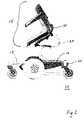
- FIG. 1is a side view of an embodiment of a wheelchair illustrating aspects of the present invention
- FIG. 2is a perspective view of the wheelchair shown in FIG. 1 ;
- FIG. 3Ais a perspective view of the wheelchair shown in FIG. 1 with portions of the chair assembly and cover removed;
- FIG. 3Bis a perspective view of the wheelchair as shown in FIG. 3A with the drive wheels and a portion of the mounting plate removed;
- FIG. 4Ais a side view of the wheelchair shown in FIG. 1 with portions of the chair assembly and cover removed;
- FIG. 4Bis side view of the wheelchair as shown in FIG. 4A with the drive wheel and a portion of the mounting plate removed;
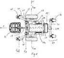
- FIG. 5is a top view of the wheelchair shown in FIG. 1 with portions of the chair assembly and cover removed;
- FIG. 6Ais a side view of the wheelchair shown in FIG. 1 on a level ground surface with the cover, drive wheel, and a portion of the mounting plate removed;
- FIG. 6Bis a side view of the wheelchair shown in FIG. 6A illustrating the wheelchair ascending a curb;
- FIG. 6Cis a side view of the wheelchair shown in FIG. 6A illustrating the wheelchair descending a curb;
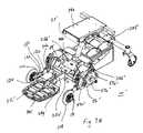
- FIG. 7Ais a perspective view of another embodiment of a wheelchair with a portion of the chair assembly and cover removed;
- FIG. 7Bis a perspective view of the wheelchair of FIG. 7A with the drive wheels and a portion of the mounting plate removed;
- FIG. 8Ais a side view of the wheelchair shown in FIG. 7A ;
- FIG. 8Bis a side view of the wheelchair shown in FIG. 7A with the drive wheel and a portion of the mounting plate removed;
- FIG. 9is a top view of the wheelchair shown in FIG. 7A ;
- FIG. 10is a side view of the wheelchair shown in FIG. 7A illustrating the wheelchair ascending a curb;
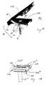
- FIG. 11is a perspective view of a portion of the chair assembly showing the chair in its forward-most position
- FIG. 12is a perspective view of a moveable portion of the chair assembly corresponding to the chair being in an intermediate position
- FIG. 13is a perspective view of the moveable portion of the chair assembly corresponding to the chair being in its forward-most position
- FIG. 14is a perspective view of another embodiment of a moveable portion of the chair assembly shown in a lower or operational position;
- FIG. 15is a perspective view of the embodiment shown in FIG. 14 showing the chair in a forward-most position
- FIG. 16is a side view of another embodiment of a moveable portion of the chair assembly shown in its lower or operational position;
- FIG. 17is a perspective view of the underside of the embodiment shown in FIG. 16 , but shown in its open configuration that corresponds to the chairs' forward-most position;
- FIG. 18is a perspective view of another embodiment of a moveable portion of the chair assembly.
- FIG. 19is a view of the preferred drive
- FIG. 20is a graph of output efficiency versus current draw for a preferred drive and a conventional drive
- FIG. 21is graph of output horsepower versus current draw for a preferred drive and a conventional drive
- FIG. 22is a graph of output speed versus torque for a preferred drive and a conventional drive.
- FIG. 23is a graph of output torque versus current draw for a preferred drive and a conventional drive.
- FIG. 1A first embodiment wheelchair 10 is shown in FIG. 1 through FIG. 5 .
- a second embodiment wheelchair 10 ′is shown in FIGS. 7A , 7 B, 8 A, and 8 B.
- First embodiment wheelchair 10includes a frame assembly 12 , a chair assembly 14 , a drive assembly 16 , a front pivot assembly 18 , and a rear wheel assembly 20 .
- Frame assembly 12 in the embodiment shownis a box-like structure that is formed of welded and/or bolted square and round tubing and formed plates.
- the frame structurewhich is generally referred to herein by reference numeral 24 , includes a central support 25 a , a rear support 25 b , a T-shaped support 25 c , a pair of pivot supports 25 d , and a footrest support 25 e .
- Frame 24is generally rigid, even though the present invention encompasses frames having joints for enhancing the suspension or any other reason.
- Central support 25 awhich is best shown in FIGS. 3A , 3 B, and 4 B, is disposed along a horizontal centerline of the wheelchair 10 . Central support is shown in FIGS. 4A and 4B , and partially shown schematically in dashed lines in FIG. 5 .
- Rear support 25 bwhich is shown in FIGS. 4A and 4B , and schematically in dashed lines in FIGS. 3A and 5 , extends upwardly from a rear portion of central support 25 a and includes a mounting plate 25 f .
- T-shaped support 25 cis disposed above and forward of central support 25 a and includes a longitudinal portion 25 g and a pair of transverse supports 25 h .
- Pivot supports 25 dextend generally downwardly from transverse supports 25 h .
- Footrest support 25 eis disposed at a forward end of longitudinal portion 25 b of T-shaped support 25 c .
- a footrest 80is coupled to footrest support 25 e.
- a housing 26 for holding batteries 82 or other power sourceis bolted or welded to frame 24 .
- a chair support, such as support post 27extends upwardly from frame 24 .
- Support post 27may be integrally formed as a portion of frame 24 or may be a separate structure.
- Support post 27as best shown in FIG. 6A , includes a substantially upright portion 28 a , a backwardly curved portion 28 b , and an upright square tube 28 c.
- Chair assembly 14includes a seat 30 for holding the wheelchair passenger, a seat post 31 for insertion into tube 28 c of support post 27 , and a hinge assembly 32 for enabling the seat 30 to pivot forward.
- Hinge assembly 32enables seat 30 to pivot relative to seat post 31 .
- hinge assembly 32includes a pair of plates or brackets 34 a and 34 b , and a hinge or pivot 36 .
- a retainer assembly 38includes a retainer plate 40 having a slot 42 , a stud 44 , and a detent recess 46 .
- Retainer plate 40preferably is attached to upper bracket 34 a by a pivot 39 .
- Stud 44preferably is affixed to lower bracket 34 b and disposed to slide within slot 42 .
- Detent recess 46is formed in retainer plate 40 as an extension of slot 42 . Stud 44 can slide into the recess 46 to temporarily and releasably lock seat 30 in its forward-most position.
- This locking mechanismcan be released by moving the retainer plate 40 by hand such that stud 44 is disposed into the long slotted portion of slot 42 , which enables stud 44 to slide in slot 42 to enable seat 30 to return to its ready position for use by a passenger
- the ready positionis shown schematically in dashed lines in FIG. 1 .
- a pair of pins 48are provided for manually locking brackets 34 a and 34 b together to prevent seat 30 from pivoting forward and keep seat 30 in its ready position.
- a hinge assembly 32 ′is coupled to a seat post 31 ′.
- Hinge assembly 32 ′includes an upper mounting plate or bracket 34 a′ and a lower mounting plate or bracket 34 b′ .
- Plates 34 a′ and 34 b′are connected at front portions thereof by a hinge or pivot 36 ′.
- a pair of gas or spring-loaded cylinders 38 ′which are biased toward the extended position, are connected between the two plates to urge upper bracket 34 b′ toward its forward-most position, as shown in FIG. 15 .
- cylinders 38 ′provide enough force to retain seat 30 in its forward position such that a person can by hand lower seat 30 against the force of cylinders 38 ′.
- cylinders 38 ′are oriented and chosen such that force tending move chair 30 from its lowermost position does not create a personnel risk.
- cylinders 38 ′preferably assist in the raising of chair 30 .
- a latch mechanism 40 ′holds lower bracket 34 b′ in its rearward-most or lower-most position, in which upper bracket 34 a′ rests on lower bracket 34 b′ , and is coupled to an ear or flange 41 a′ on upper plate 34 a′ .
- the lower-most positionis shown in FIG. 14 .
- Latch mechanism 40 ′includes a retractable pin 48 a′ , which preferably may be spring loaded or, alternatively, retractable by threading onto threads fixed onto one of the brackets.
- pin 48 a′is housed in a body 49 ′, which is affixed to an ear or flange 41 a′ that extends from upper bracket 34 a′ .
- Body 49 ′preferably is threaded onto a nut that is affixed to flange 41 a′.
- Lower bracket 34 b′includes connections for cylinders 38 ′, a connection for seat post 31 ′, and a downwardly projecting ear or flange 41 b′ .
- Flange 41 b′preferably has a curved portion that forms a smooth transition between a substantially vertical portion of flange 41 b′ and the major surface of bracket 34 b′ .
- pin 48 a′contacts the curved portion of flange 41 a′ and gradually retracts.
- Pin 48 a′aligns with a hole 48 b′ formed in flange 41 a′ when upper bracket 34 a′ is fully engaged with lower bracket 34 b′ .
- Pin 48 a′then extends into hole 48 b′ to retain upper bracket 34 b′ onto lower bracket 34 a′.
- FIGS. 16 and 17show an alternative embodiment of the assembly that enables seat 30 (not shown in FIGS. 17 and 17 for clarity) to move foreword.
- the brackets 34 a′′ and 34 b′′ of the embodiment of FIGS. 16 and 17are similar to those shown in FIGS. 14 and 15 except latch mechanism 40 ′ (and its cooperating structure) is omitted in favor of a locking handle 40 ′′ (and its cooperating structure) that is employed to retain upper bracket 34 a′′ and lower bracket 34 b′′ together.
- upper bracket 34 a′′includes a pair of tabs 41 a′′ that form a slot 42 a ′′. In its lower position, slot 42 a ′′ receives an alignment bar 42 b ′′ that is part of lower bracket 34 b′′ .
- Brackets 34 a′′ and 34 b′′are coupled together by a hinge or pivot 36 ′′.
- Locking handle 40 ′′includes a handle portion 48 ′′ and a pair of cam portions 49 ′′ that are connected to tabs 41 a′′ via a hinge 47 ′′. In the lower position, shown in FIG. 16 , can portions 49 ′′ engage alignment bar 42 b ′′ to retain brackets 34 a′′ and 34 b′′ together. Upward rotation of handle mechanism 40 ′′ disengages cam portions 49 ′′ from alignment bar 42 b′′ and enables upper bracket 34 a′′ to move upward relative to lower bracket 34 b′′ .
- air cylindersas shown in FIGS. 14 and 15 (not shown in FIGS.
- brackets 34 a′′ and 34 b′′are connected between brackets 34 a′′ and 34 b′′ to urge seat 30 toward its forward-most position (or more preferably to aid in the manual raising of seat 30 toward its forward-most position), and to retain it in the forward-most position, until manually returned to its lower position.
- FIG. 18illustrate another embodiment of an assembly to enable a seat 30 to move forward
- a slide assembly 32 ′′′is mounted onto a lower chair assembly bracket 34 b′′ .
- a corresponding upper chair assembly bracket 34 a′′′which is shown schematically in dashed lines, is rigidly coupled to a chair 30 (not shown in FIG. 18 ).
- a pair of slidesenables upper bracket 34 a′′′ to slide on lower bracket 34 b′′′ , which is affixed to a support 31 .
- Support post 27 ′′′is generally identical to post 27 described above.
- Each one of the pair of slidesincludes a slide member 33 a that is fixed to the upper bracket 34 a′′′ and a cooperating slide member 33 b that is fixed to the lower bracket 34 b′′′ .
- Slide members 33 a and 33 bmay have any configuration that will enable seat 30 to slide relative to lower bracket 34 b′′′ , including conventional slides.
- a wheelchair 10includes a pair of drive assemblies 16 and pivot assemblies 18 .
- the left combination of drive assembly 16 and pivot assembly 18is the mirror image of the right combination of drive assembly 16 and pivot assembly 18 .
- each assembly drive 16 and pivot assembly 18is described in detail herein, as it is clear that the description applies equally to each one of the left and right assemblies 16 and 18 .
- Drive assembly 16includes a pair of drives 50 , each of which includes a motor 52 , a gearbox 54 , and a mounting plate 56 . Each one of the drive assemblies is connected to one of a pair of drive wheels 58 .
- Drive assembly 16is pivotally coupled to frame assembly 12 by the pivot 29 between frame structure 24 and mounting plate 56 .
- Motor 52preferably is oriented with its centerline (that is, the central axis of its output shaft) parallel to the output shaft of gearbox 54 , which is coupled to a drive wheel 58 as shown in the figures.
- a longitudinal centerline of the output shaft of gearbox 54which preferably is a single reduction gearbox, is collinear with the drive wheel rotational axis, which is designated C-DW.
- Motor 52may be oriented such that its centerline is collinear with or—as shown in the figures—is parallel to, but offset from, drive wheel rotational axis C-DW and the output shaft of gearbox 54 .
- Drives 50preferably are mounted transverse to the direction of translation of the wheelchair. As illustrated by arrow F shown for example in FIG. 6A , the direction of translation is parallel to a ground plane surface 200 on which the wheelchair moves forward and perpendicular to the rotational axis C-DW of the drive wheels.
- the transverse axisis parallel to the axis of rotation of the drive wheels and parallel to the level ground.
- the orientation of rotational or pivotal axesare based on the wheelchair at rest on level ground surface 200 with all wheels oriented to roll straight forward (direction F).
- the present inventionencompasses motors 52 having a centerline (that is, the central axis of its output shaft) that is not parallel to the drive wheel rotational axis C-DW.
- the present invention(that is, as recited in a claim) is not limited to any relationship or orientation of any part of the drive relative to the frame unless such relationship or orientation is explicitly stated in the claim.
- Drive 50is rigidly affixed to mounting plate 56 .
- Mounting plate 56preferably is planar and oriented perpendicular to rotational axis C-DW of drive wheels 58 .
- mounting plate 56includes a mounting portion 57 a to which drive 50 is coupled and a projection 57 b that extends forward and downward.
- gearbox 54is bolted onto mounting portion 57 a .
- Projection 57 bhouses a portion of a pivot 29 for pivotally connecting mounting plate 56 to pivot support 25 d of frame 24 .
- the configuration of drive 50aids in locating and configuring battery compartment 26 , but is not required generally to obtain other benefits of the inventive aspects of wheelchair 10 .
- the term “battery compartment”encompasses not only enclosures for housing the batteries but also volumes (even if unenclosed) in which the batteries for powering the motors resides.
- the configuration of drives 50also provides improvement in efficiency compared with conventional right angle drives.
- drive 50which is shown in FIG. 19 , includes a 24 volt DC motor rated for 3.0 amps and a single reduction gearbox having a reduction ratio of 17.75:1. The no-load speed rating is 166 rpm.
- FIG. 20 through 23illustrate some benefits of preferred drive 50 compared with a conventional worm-gear, right angle drive having a 4500 rpm motor rated for 2.1 amps (at no load) and a 32:1 gear ratio.
- FIG. 20is a graph of output efficiency versus current draw
- FIG. 21is graph of output horsepower versus current draw
- FIG. 22is a graph of output speed versus torque
- FIG. 23is a graph of output torque versus current draw. Because of the higher efficiency of the preferred drive 50 , a smaller motor may be used, and therefore a smaller controller and batteries may be used in some circumstances.
- Pivot assembly 18includes a front arm, such as caster arm 60 , a swivel bearing 62 , a caster support 64 , and a caster wheel 66 .
- Caster arm 60is rigidly coupled to drive 50 via motor mounting plate 56 .
- a rearward end of caster arm 60is affixed to an upper portion of mounting plate 56 .
- Bearing 62preferably has a barrel that is oriented vertically to enable caster wheel 66 to swivel or turn about a vertical axis to enhance the capability of wheelchair 10 to turn.
- Caster support 64includes a fork on which an axle or bearing of caster wheel 66 is fixed.
- Rear wheel assembly 20includes an articulating beam 70 that is coupled to frame 24 at mounting plate 25 f , a pair of swivel bearings 72 , a pair of rear caster supports 74 , and a pair of rear casters 76 .
- Beam 70is coupled to mounting plate 25 f by any means that enables beam 70 to articulate to adapt to changes in the ground, such as a pivot having a horizontal pivot axis. Preferably, this pivot is located rearward of the battery compartment 26 .
- the articulating structure and function of rear caster beamsis shown in U.S. Pat. No. 6,129,165, which is incorporated herein by reference in its entirety.
- Bearings 72are disposed on distal ends of beam 70 , and each preferably includes a barrel that is vertically oriented to enable the corresponding caster 76 to swivel or turn to enhance the capability of wheelchair 10 to turn.
- Caster support 74includes a fork on which an axle or bearing of caster wheel 76 is fixed.
- Transverse mounting of drives 50enhances the ability to accomplish and configure the combination of generally rearward battery location and an articulating, transverse beam 70 .
- the motorswings about the gearbox output shaft to impart motion to the front caster arm, as for example shown in U.S. Pat. No. 6,129,165.
- Providing clearance for the swinging motion for such longitudinally mounted motorssacrifices space that may be used for locating the batteries.
- Support post 27and preferably the connection between support post 27 and frame 24 , is disposed rearward of drive motors 52 , preferably generally rearward of drive assembly 16 , and preferably rearward of the drive wheel axis of rotation C-DW.
- the connection between support post 27 and frame 24may be the location at which the load from chair assembly 14 and the passenger is transmitted to frame 24 .
- Battery housing 26and thus batteries 82 or other power source, preferably is disposed substantially, and preferably entirely, rearward of drive wheel axis C-DW, and preferably substantially, and more preferably entirely, rearward of the support post 27 connection to frame 24 .
- the inventionencompasses the center of gravity of batteries 82 or other power source being located rearward of the support 27 connection and/or rearward of drive wheel axis C-DW.
- the wheelchair coverwhich typically covers the batteries and mechanical components, may be removable or configured with a hatch (not shown in the figures) to enable direct access to the batteries.
- the configuration of wheelchair 10enables batteries to be accessed from the behind the drive wheels, and preferably from the rear center (that is, the 6 o'clock position when viewed from above).
- This functionenables only one technician to make a sales call to a wheelchair owners home, rather than requiring additional people to help the driver from the seat.
- the present inventiongenerally encompasses structures in which the batteries are not accessible from behind the drive wheels, no aspect of the present invention is limited to enabling access to batteries 82 as described herein, unless such limitation is expressly recited in the claim.
- the loads borne by frame 24are transmitted to the ground via drive wheels 58 , front casters 66 , and rear casters 76 .
- the location of pivot 29will affect the weight distribution of wheelchair 10 .
- the position of pivot 29 forward of drive wheel axis C-DWcauses front casters 66 to bear a vertical load while wheelchair 10 is at rest, as mounting plate 56 is supported by drive wheel 58 via its axle.
- Configuring the wheelchair such that front casters 66 bears a vertical load during steady-speed operation on level ground and/or while at rest on level groundmay, in some circumstances, enhance the stability and stable feel of a wheelchair, although load-bearing casters are not required.
- the position of pivot 29may be chosen to achieve the desired weight distribution and the desired downward load borne by front casters 66 .
- the weight distribution and magnitude of load borne by the castersmay be chosen according to such parameters as desired stability of the particular wheelchair during operation on level ground and while ascending and descending a step, motor torque and horsepower, other wheelchair dimensions (such as the horizontal distance from drive wheel axis C-DW to the rear casters), overall wheelchair weight, and like parameters.
- pivot axis 29preferably is spaced apart from the front wheel axis by a horizontal dimension that is between 40% and 65%, more preferably between 45% and 60%, and even more preferably about 54% of the horizontal dimension between drive wheel axis C-DW and the front caster axis.
- Pivot axis 29may be spaced apart from front wheel axis C-RC by less than or about 30% of the distance between the drive wheel axis and the front caster axis.
- Front casters 66bear approximately 30% of the wheelchair load.
- a “horizontal” dimension or distance, when referring to pivot position,is measured parallel to a level ground plane in a direction of straight-ahead travel of the wheelchair (that is, perpendicular to the drive wheel axis) while the wheelchair is at rest.
- a “vertical” distance or dimension, or height, when referring to pivot position,is perpendicular to a level ground plane while the wheelchair is at rest.
- pivot assembly 18enables the front suspension of wheelchair 10 to function without a spring bias on caster 66 because of the downward force applied to casters 66 described above.
- Forgoing biasing springs in the anti-tip wheelseliminates the step of adjusting spring bias for the weight of the wheelchair occupant.
- the present inventionis not limited to wheelchairs lacking springs, regardless of the type of front wheels employed.
- drive wheel axis C-DWhas a height H 1
- a centerline of pivot 29defines a pivot axis C-P that has a height H 2
- a centerline of front caster 66defines a front caster axis C-FC that has a height H 3
- front caster axis height H 3is approximately the same as or more than pivot axis height H 2 .
- the inventorsbelieve that it is advantageous for pivot axis height H 2 to be approximately below a line drawn between the drive wheel axis and axis of rotation of front caster 66 .
- Wheelchair 10may be driven forward until front caster 66 contacts face 202 or, as shown in FIG. 6A , corner 203 . Applying torque to drive wheels 58 urges front caster 66 against corner 203 .
- front caster 66overcomes step 201 because of a force couple created by horizontal components of the driving force of wheelchair 10 and a reaction force from step 201 .
- a vertical, upward component of the reaction force or impulse applied at the walltends to raise caster 66 (even if the height of curb face 202 is greater than the caster radius).
- This upward forcealso enables or enhances wheelchair 10 to overcome a step having a height that is approximately the same as caster axis height H 3 .
- FIG. 6Billustrates the partially ascended position in which front caster 66 is disposed on step upper surface 204 while drive wheel 58 and rear caster 76 are disposed on ground surface 200 .
- Front arm 60 and mounting plate 56have been pivoted clockwise (as oriented in FIG. 6B ) from the at-rest position in which all six wheels are in contact with ground surface 200 .
- frame 24 of wheelchair 10tips slightly upward from its at rest position, as mounting plate 56 pivots—clockwise as oriented in FIG. 6 B—about drive wheel axis C-DW.
- front arm 60pivots as caster 66 moves from ground surface 200 to step upper surface 202 , and the corresponding pivoting of mounting plate 56 about drive wheel axis C-DW results in a corresponding pivoting of pivot 29 about drive wheel axis C-DW.
- Upward movement of pivot 29results in a upward movement of the forward portion of frame 24 .
- frame 24tips by an angle A 1 of approximately 2.5 degrees upon front caster 66 initially touching lower surface 212 .
- FIG. 6Cillustrates wheelchair 10 in the process of descending a step 210 , which includes a face 211 and a lower surface 212 .
- Front caster 66is shown on the lower surface 212 of the step and drive wheels 58 and rear wheels 76 are on the ground surface 200 .
- front caster 66is urged from the upper surface 100 to the lower surface 212 by the downward force from frame 24 transmitted to plate 56 via pivot 29 .
- frame 24 of wheelchair 10tips slightly forward from its at rest position, as mounting plate 56 pivots—counterclockwise as oriented in FIG. 6 C—about drive wheel axis C-DW.
- front arm 60pivots as caster 66 moves from step upper surface 200 to step lower surface 212 , and the corresponding pivoting of mounting plate 56 about drive wheel axis C-DW results in a corresponding pivoting of pivot 29 about drive wheel axis C-DW.
- Downward movement of pivot 29results in a downward movement of the forward portion of frame 24 .
- frame 24tips by an angle A 2 of approximately 3 degrees upon front caster 66 initially touching lower surface 212 .
- the present inventionencompasses a wheelchair having one or both of the vertical and horizontal pivot locations described herein, which will be referred in this and the following two paragraphs as a low pivot and a forward pivot, respectively.
- low pivotsmay have been disfavored because of the need for clearance over the ground, even when the ground is uneven. Further, the pivot must clear an obstacle, such as a curb, during climbing, which may require lifting the frame at the pivot by a change in height that is greater than if the pivot was at a higher location. Further, considering lifting of the front pivot, forward pivot locations may have been disfavored because of diminished mechanical advantage of forward pivot positions.
- a force applied through the wheelchair via front caster 66 onto vertical obstacle face 22creates an upward component of the force vector by the nature of the orientation of the pivots C-P and C-FC. This upward component of force may be helpful for ascending especially high obstacles, as explained above.
- the low pivotalso aids even in circumstances in which the pivot axis C-P is at the same height or slightly higher than caster axis C-FC by keeping the downward component of the force near zero or small, such that motor torque may be used to climb the obstacle.
- the configuration described herein, with any combination of low pivot, forward pivot, rigid coupling together of the drive assembly and front arm, transverse drives, and rear battery locationprovides a combination of beneficial wheelchair stability and curb climbing capabilities.
- the configuration shownnaturally has good forward stability (that is, wheelchair 10 does not easily tip forward), and the rear articulating transverse beam enhances rearward stability (especially backwards tipping) compared with separately sprung rear arms.
- FIGS. 7A , 7 B, 8 A, 8 B, and 9illustrate the second embodiment, in which a wheelchair 10 ′ includes a frame assembly 12 ′, a chair assembly 14 ′, a drive assembly 16 ′, a front pivot assembly 19 , and a rear wheel assembly 20 ′.
- Structure of wheelchair 10 ′ that corresponds to structure of the first embodiment wheelchair 10is designated with a prime (′) symbol after the reference numeral.
- Chair assembly 14 ′is essentially the same as the chair assembly 14 shown in FIGS. 1-5 and 11 - 13
- rear wheel assembly 20 ′is essentially the same as rear wheel assembly 20 shown in FIGS. 1-5 . Accordingly, descriptions of chair assembly 14 ′ and rear wheel assembly 20 ′ are omitted from the description of second wheelchair embodiment 10 ′.
- Frame assembly 12 ′ in the embodiment shown in FIGS. 7A and 7Bis a rigid, box-like structure that is formed of welded and/or bolted square and round tubing and formed plates.
- the frame structurewhich is generally referred to herein by reference numeral 24 ′, includes a central support 25 a′ , a rear support 25 b′ , a T-shaped support 25 c′ , a pair of pivot supports 25 d′ , and a footrest support 25 e′.
- Central support 25 a′which is best shown in FIGS. 8A , 8 B, and (schematically in dashed lines) FIG. 9 , is disposed along a horizontal centerline of the wheelchair 10 ′.
- Rear support 25 b′which is shown in FIG. 9 , extends upwardly from a rear portion of central support 25 a′ and includes a mounting plate 25 f .
- T-shaped support 25 c′is disposed above and forward of central support 25 a′ and includes a longitudinal portion 25 g′ and a pair of transverse supports 25 h′ .
- Pivot supports 25 d′preferably are substantially vertical plates that extend generally upwardly from transverse supports 25 h′ .
- Footrest support 25 e′is disposed at a forward end of longitudinal portion 25 b of T-shaped support 25 c .
- a footrest 80 ′is coupled to footrest support 25 e′ .
- a housing 26 ′ for holding batteries 82 ′ and a support post 27 ′are generally the same as described above with respect to first embodiment wheelchair 10 .
- Drive assembly 16 ′ of second embodiment wheelchair 10 ′includes a pair of drives 50 ′, each of which includes a motor 52 ′ and a gearbox 54 ′, a mounting plate 56 ′, and a pair of drive wheels 58 ′.
- Motor 52 ′preferably is oriented with its centerline (that is, the central axis of its output shaft) parallel to the output shaft of gearbox 54 ′, which is coupled to a drive wheel 58 ′ as shown in the figures.
- a longitudinal centerline of the output shaft of gearbox 54 ′is collinear with the drive wheel rotational axis, which is designated C-DW.
- Motor 52 ′may be oriented such that its centerline is collinear with or—as shown in the figures—is parallel to, but offset from, drive wheel rotational axis C-DW and the output shaft of gearbox 54 ′. Accordingly, drives 50 ′ preferably are mounted transverse to the direction of translation of the wheelchair. The forward direction of wheelchair translation is indicated in FIG. 8A by arrow F. Also, the present invention encompasses motors 52 ′ having a centerline (that is, the central axis of its output shaft) that is not parallel to the drive wheel rotational axis C-DW unless such relationship is explicitly set forth in the claims.
- Drive 50 ′is rigidly affixed to mounting plate 56 ′.
- Mounting plate 56 ′is pivotally connected to pivot support 25 d′ by pivot 29 ′, as best shown in FIGS. 7A and 7B .
- Mounting plate 56 ′preferably is planar and oriented perpendicular to rotational axis C-DW of drive wheels 58 ′.
- Mounting plate 56 ′includes a motor-mounting portion 57 a′ to which drive 50 ′ is bolted, a front projection 57 b′ that extends forward from mounting portion 57 a′ , and a rear projection that extends rearward from mounting portion 57 a′ .
- front projection 57 b′provides a surface for the attachment of the arm of pivot assembly 19 ;
- rear projection 57 c′provides a surface for attachment of a bracket to which a spring is mounted.
- Pivot assembly 19includes a forward-extending front arm, such as fixed wheel or anti-tip wheel arm 90 , and a suspension assembly 91 .
- Arm 90includes a front end 92 a to which an adjustment plate 102 is connected and a rear end 92 b that is affixed to front projection 57 b′.
- Adjustment plate 102includes a pivotable connection 120 , holes 122 formed through plate 102 , and a bearing mounting 124 to which a front wheel 108 is attached.
- a bolt or pin 126extends horizontally through arm front end 92 a and through one of holes 122 .
- the height of wheel 108may be adjusted by removing pin 126 , pivoting plate 102 up or down to a desired position, and replacing pin 126 into another one of holes 122 .
- the height of wheel 108may be adjusted to be closely spaced apart from ground plane surface 200 or adjusted such that the rotational axis of wheel 108 is higher than an expected curb height.
- Adjustment plate 102is shown for illustration, and the present invention is not limited to wheelchairs having a front wheel height adjustment nor to a particular configuration of a height adjustment mechanism.
- Suspension assembly 91preferably includes a front spring 94 a and a rear spring 94 b .
- Front spring 94 ahas an upper end that is pivotally connected to a mounting bracket 96 a that extends from an upper portion of pivot support 25 d′ .
- a lower end of spring 94 ais pivotally connected to an intermediate portion of arm 90 between arm front end 92 a and arm rear end 92 b , and thus spring 94 a acts on arm 90 forward of mounting plate 56 ′ and rearward of adjustment plate 102 .
- Rear spring 94 bhas an upper end that is pivotally connected to a mounting bracket 96 b that extends rearward from pivot support 25 d′ and a lower end that is pivotally connected to a rearward portion 57 c′ of mounting plate 56 ′.
- front spring 94 aincludes a threaded rod and adjustment nut 128 to adjust the spring force and height of spring 94 a.
- FIG. 10illustrates the operation of wheelchair 10 ′ as it encounters a corner 203 of curb 201 . Because the height of the axis of fixed wheel 108 is greater than the height of curb 201 , wheel 108 rides over curb 201 when urged forward by the wheelchair drive 50 ′. Arm 90 and mounting plate 56 ′ rotate clockwise (as oriented in FIGS. 8A and 8B ) until wheel 108 overcomes corner 203 to reach upper surface 204 . Wheelchair 10 ′ continues moving forward until drive wheels 58 ′ contact and overcome curb 201 .
- frame 12 ′Upon initially mounting or ascending curb 201 , frame 12 ′ preferably tilts slightly upward.
- the position of the pivoting connection 29 ′may be chosen to cooperate with the operation of wheel 108 and drive wheels 58 ′, as will be understood by persons familiar with wheelchair design and configuration in view of the present disclosure.
- the position of pivot connection 29 ′enhances the capability of arm 90 of wheelchair 10 ′ to rise relative to the ground in response to an increase in motor torque and/or to wheelchair acceleration.
- Front casters 66 of first embodiment wheelchair 10generally remain in contact with the ground surface in response to most applications of motor torque and/or acceleration.
- the present inventionis not limited by the capability or lack of capability of the arms, such as arms 60 or 90 , raising in response to application of motor torque, acceleration, or like operations.
- wheelchairs 10 and 10 ′ and their respective subsystemsare for illustration purposes, and the present invention is not intended to the particular descriptions provided herein, nor is the designation of parts into particular subsystems intended to limit the scope of the invention in any way.
- the description of the frame assemblydoes not limit the scope of the invention to devices having a rigid frame, but rather the invention encompasses all frame structures, including those having flexible or movable structure; describing the hinge assembly as a portion of the chair assembly should not be construed to limit the invention to such structure; and describing components of the wheelchair as part of the pivot assembly is not intending to be limiting.
- hinge assembly structure and slide assembly structurefor moving the seat, the frame structures, the chair assembly structure, the drive assembly structures, the pivot assembly structures, and rear beam structure are described herein for illustration purposes, and are not intended to limit the scope of the invention except for the particular structure that is explicitly recited in the claim.
Landscapes
- Public Health (AREA)
- Health & Medical Sciences (AREA)
- Life Sciences & Earth Sciences (AREA)
- Animal Behavior & Ethology (AREA)
- General Health & Medical Sciences (AREA)
- Veterinary Medicine (AREA)
- Engineering & Computer Science (AREA)
- Combustion & Propulsion (AREA)
- Transportation (AREA)
- Mechanical Engineering (AREA)
- Chemical & Material Sciences (AREA)
- Handcart (AREA)
- Arrangement Or Mounting Of Propulsion Units For Vehicles (AREA)
Abstract
Description
Claims (51)
Priority Applications (5)
| Application Number | Priority Date | Filing Date | Title |
|---|---|---|---|
| US11/486,638US7766106B2 (en) | 2005-07-14 | 2006-07-14 | Powered wheelchair configurations and related methods of use |
| US12/822,464US8292010B2 (en) | 2005-07-14 | 2010-06-24 | Powered wheelchair configurations and related methods of use |
| US13/656,833US8408343B2 (en) | 2005-07-14 | 2012-10-22 | Powered wheelchair configurations and related methods of use |
| US13/854,330US9333130B2 (en) | 2005-07-14 | 2013-04-01 | Powered wheelchair configurations and related methods of use |
| US15/093,538US9872804B2 (en) | 2005-07-14 | 2016-04-07 | Powered wheelchair configurations and related methods of use |
Applications Claiming Priority (3)
| Application Number | Priority Date | Filing Date | Title |
|---|---|---|---|
| US69920105P | 2005-07-14 | 2005-07-14 | |
| US72753705P | 2005-10-17 | 2005-10-17 | |
| US11/486,638US7766106B2 (en) | 2005-07-14 | 2006-07-14 | Powered wheelchair configurations and related methods of use |
Related Child Applications (1)
| Application Number | Title | Priority Date | Filing Date |
|---|---|---|---|
| US12/822,464ContinuationUS8292010B2 (en) | 2005-07-14 | 2010-06-24 | Powered wheelchair configurations and related methods of use |
Publications (2)
| Publication Number | Publication Date |
|---|---|
| US20070107955A1 US20070107955A1 (en) | 2007-05-17 |
| US7766106B2true US7766106B2 (en) | 2010-08-03 |
Family
ID=37401088
Family Applications (5)
| Application Number | Title | Priority Date | Filing Date |
|---|---|---|---|
| US11/486,638Active2028-03-15US7766106B2 (en) | 2005-07-14 | 2006-07-14 | Powered wheelchair configurations and related methods of use |
| US12/822,464Active2027-01-28US8292010B2 (en) | 2005-07-14 | 2010-06-24 | Powered wheelchair configurations and related methods of use |
| US13/656,833ActiveUS8408343B2 (en) | 2005-07-14 | 2012-10-22 | Powered wheelchair configurations and related methods of use |
| US13/854,330Expired - Fee RelatedUS9333130B2 (en) | 2005-07-14 | 2013-04-01 | Powered wheelchair configurations and related methods of use |
| US15/093,538ActiveUS9872804B2 (en) | 2005-07-14 | 2016-04-07 | Powered wheelchair configurations and related methods of use |
Family Applications After (4)
| Application Number | Title | Priority Date | Filing Date |
|---|---|---|---|
| US12/822,464Active2027-01-28US8292010B2 (en) | 2005-07-14 | 2010-06-24 | Powered wheelchair configurations and related methods of use |
| US13/656,833ActiveUS8408343B2 (en) | 2005-07-14 | 2012-10-22 | Powered wheelchair configurations and related methods of use |
| US13/854,330Expired - Fee RelatedUS9333130B2 (en) | 2005-07-14 | 2013-04-01 | Powered wheelchair configurations and related methods of use |
| US15/093,538ActiveUS9872804B2 (en) | 2005-07-14 | 2016-04-07 | Powered wheelchair configurations and related methods of use |
Country Status (5)
| Country | Link |
|---|---|
| US (5) | US7766106B2 (en) |
| AU (1) | AU2006270274A1 (en) |
| CA (1) | CA2614816A1 (en) |
| GB (1) | GB2441290A (en) |
| WO (1) | WO2007011668A2 (en) |
Cited By (29)
| Publication number | Priority date | Publication date | Assignee | Title |
|---|---|---|---|---|
| US20100084209A1 (en)* | 2007-02-08 | 2010-04-08 | Invacare Corporation | Wheelchair suspension |
| US20100258363A1 (en)* | 2005-07-14 | 2010-10-14 | Pride Mobility Products Corporation | Powered wheelchair configurations and related methods of use |
| US20110012316A1 (en)* | 2009-07-14 | 2011-01-20 | Merits Health Products Co. Ltd. | Wheel set structure of an electric wheelchair |
| US20110083914A1 (en)* | 2009-10-12 | 2011-04-14 | Pride Mobility Products Corporation | Wheelchair |
| US20110215540A1 (en)* | 2007-08-24 | 2011-09-08 | Levo Ag Wohlen | Vehicle with central wheel drive, in particular a wheelchair or stand-up wheelchair |
| US8172016B2 (en) | 2000-10-27 | 2012-05-08 | Invacare Corporation | Obstacle traversing wheelchair |
| US8172015B2 (en) | 2001-10-10 | 2012-05-08 | Invacare Corporation | Wheelchair suspension |
| US20120223514A1 (en)* | 2009-11-15 | 2012-09-06 | Invacare Corp. | Wheelchair |
| US8297388B2 (en) | 2007-01-12 | 2012-10-30 | Invacare International Sarl | Wheelchair with suspension arms |
| US8534679B2 (en) | 2002-10-25 | 2013-09-17 | Invacare Corporation | Suspension for wheeled vehicles |
| US8573341B2 (en) | 2001-10-19 | 2013-11-05 | Invacare Corporation | Wheelchair suspension |
| US8910975B2 (en) | 2007-02-14 | 2014-12-16 | Invacare Corporation | Wheelchair with suspension |
| US8919626B1 (en) | 2011-05-05 | 2014-12-30 | Ronald E. Smith | Power chair carrier system |
| US8931583B2 (en) | 2010-06-24 | 2015-01-13 | Invacare Corporation | Wheelchair |
| US20150028559A1 (en)* | 2013-07-24 | 2015-01-29 | Next Generation Mobility Pty Ltd | Wheelchair structure and suspension assembly |
| US9010470B2 (en) | 2009-10-09 | 2015-04-21 | Invacare Corporation | Wheelchair suspension |
| US9308143B2 (en) | 2012-02-15 | 2016-04-12 | Invacare Corporation | Wheelchair suspension |
| US9351889B2 (en) | 2013-12-16 | 2016-05-31 | Pride Mobility Products Corporation | Elevated height wheelchair |
| US20160270990A1 (en)* | 2013-07-12 | 2016-09-22 | Permobil Ab | Wheelchair with tilt capability |
| US9532912B2 (en) | 2010-03-16 | 2017-01-03 | Invacare Corporation | Wheelchair seat assembly |
| US10335330B2 (en) | 2017-03-02 | 2019-07-02 | Travelsys4u Ltd. | Motor-driven chair steered by seat rotation |
| US11191685B2 (en) | 2016-02-27 | 2021-12-07 | Pride Mobility Products Corporation | Adjustable height wheelchair |
| WO2021245181A1 (en)* | 2020-06-05 | 2021-12-09 | Otto Bock Mobility Solutions Gmbh | Wheelchair |
| US11213441B2 (en) | 2002-10-25 | 2022-01-04 | Invacare Corporation | Suspension for wheeled vehicles |
| US11617696B2 (en) | 2018-07-19 | 2023-04-04 | Permobil Ab | Mobility device |
| US11826291B2 (en)* | 2018-07-19 | 2023-11-28 | Permobil Ab | Mobility device |
| US11903887B2 (en) | 2020-02-25 | 2024-02-20 | Invacare Corporation | Wheelchair and suspension systems |
| US11957631B2 (en) | 2022-07-13 | 2024-04-16 | Invacare Corporation | Wheelchair and suspension systems |
| US12409085B2 (en) | 2022-07-07 | 2025-09-09 | Permobil Ab | Powered midwheel drive wheelchair with standing capability |
Families Citing this family (26)
| Publication number | Priority date | Publication date | Assignee | Title |
|---|---|---|---|---|
| US7896394B2 (en) | 2005-08-18 | 2011-03-01 | Sunrise Medical Hhg, Inc. | Midwheel drive wheelchair with independent front and rear suspension |
| AU2014202550B2 (en)* | 2009-10-09 | 2015-08-06 | Invacare Corporation | Wheelchair suspension |
| US8851214B2 (en) | 2010-07-15 | 2014-10-07 | Permobil Ab | Electric mid-wheel drive wheelchair |
| CN102283749B (en)* | 2011-06-27 | 2013-04-03 | 胡达广 | Electric wheelchair for multiple road conditions |
| US9398990B2 (en) | 2011-07-06 | 2016-07-26 | W Mark Richter | Motion-based power assist system for wheelchairs |
| US8783394B1 (en) | 2012-05-10 | 2014-07-22 | T3 Motion, Inc. | Drive wheel suspension |
| USD701796S1 (en)* | 2012-10-03 | 2014-04-01 | T3 Motion, Inc. | Wheel suspension and drive system |
| FR3001632B1 (en)* | 2013-02-01 | 2015-02-20 | Power 4 4 | VERTICALIZING WHEELCHAIR FOR PERSON WITH REDUCED MOBILITY |
| US9144525B2 (en)* | 2013-03-14 | 2015-09-29 | Max Mobility, Llc. | Motion assistance system for wheelchairs |
| CN103230321B (en)* | 2013-05-08 | 2015-07-15 | 河北工业大学 | Frame of composite wheel leg type wheelchair |
| JP6141161B2 (en)* | 2013-09-25 | 2017-06-07 | 株式会社クボタ | Traveling vehicle |
| TWI609800B (en)* | 2014-08-15 | 2018-01-01 | Linked frame with stabilizer | |
| CN204368366U (en)* | 2015-01-06 | 2015-06-03 | 好孩子儿童用品有限公司 | A kind of children's drift car |
| US9795524B2 (en) | 2015-02-24 | 2017-10-24 | Max Mobility, Llc | Assistive driving system for a wheelchair |
| CN104840313B (en)* | 2015-05-22 | 2017-06-30 | 浙江全球跑电动轮椅有限公司 | A kind of accumulator mounting structure of electric wheelchair |
| US10123921B2 (en)* | 2015-07-24 | 2018-11-13 | Stryker Corporation | Patient support apparatus |
| US10052247B2 (en)* | 2015-08-24 | 2018-08-21 | Dream Roller Mobility, LLC | Wheelchair with four wheel independent suspension and modular seating |
| US10167051B1 (en) | 2017-12-12 | 2019-01-01 | Max Mobility, Llc | Assistive driving system for a wheelchair and method for controlling assistive driving system |
| DE102017222940A1 (en) | 2017-12-15 | 2019-06-19 | Shimano Inc. | Actuator assembly and actuator |
| TWI671066B (en)* | 2018-01-24 | 2019-09-11 | 緯創資通股份有限公司 | Mobile carrier |
| CN108516027B (en)* | 2018-05-17 | 2024-03-15 | 香港中文大学(深圳) | Support leading wheel structure and have cable climbing robot of this structure |
| CN108852660B (en)* | 2018-07-17 | 2020-04-24 | 冯英 | Front wheel suspension structure of electric wheelchair |
| CN112220619B (en)* | 2020-05-19 | 2025-02-11 | 广州市机电高级技工学校(广州市机电技师学院、广州市机电高级职业技术培训学院) | An electric folding wheelchair capable of going up and down stairs |
| CN112158276A (en)* | 2020-10-26 | 2021-01-01 | 大陆智源科技(北京)有限公司 | Balancing device and mobile robot |
| USD1033279S1 (en) | 2022-08-22 | 2024-07-02 | Three Oceans, LLC | Scooter |
| WO2024124321A1 (en)* | 2022-12-16 | 2024-06-20 | Green Innovation Indústria De Equipamentos Médicos Ltda. | Structural arrangement applied to removable wheels and couplable off-road kit for a motorized wheelchair |
Citations (81)
| Publication number | Priority date | Publication date | Assignee | Title |
|---|---|---|---|---|
| US3104112A (en) | 1962-07-02 | 1963-09-17 | Jesse W Crail | Stair climbing wheel chair |
| US3213957A (en)* | 1962-08-27 | 1965-10-26 | Wessex Ind Poole Ltd | Self-propelled wheel chair |
| US3520378A (en) | 1966-06-23 | 1970-07-14 | Reginald Arthur Slay | Motor-driven wheeled vehicles |
| US3794132A (en) | 1972-08-16 | 1974-02-26 | Lakeside Mfg Inc | Self-propelled wheelchair |
| US3807520A (en) | 1971-12-15 | 1974-04-30 | D Chisholm | Motorized wheelchair |
| US3827718A (en) | 1973-05-30 | 1974-08-06 | P Curry | Wheel chair |
| FR2215054A5 (en) | 1973-01-23 | 1974-08-19 | Folco Zambelli Gian Matteo | |
| US3952822A (en) | 1973-03-19 | 1976-04-27 | Stiftelsen Teknisk Hjalp At Handikappade Permobilstiftelsen | Electrically powered wheel-chair for indoor and outdoor use |
| US4000912A (en) | 1975-02-21 | 1977-01-04 | Mse Corporation | Shock absorber |
| US4128137A (en) | 1976-02-24 | 1978-12-05 | National Research Development Corporation | Peripatetic vehicles |
| FR2399822A1 (en) | 1977-08-09 | 1979-03-09 | Dupont Lit Sa | Folding wheel chair for handicapped people - consists of frame on two drive wheels, with seat mounted by parallel arms raised and lowered by jack |
| US4245847A (en) | 1979-05-24 | 1981-01-20 | Christopher Knott | Wheelchair |
| GB2051702A (en) | 1979-05-24 | 1981-01-21 | Secr Defence | Wheel chair safety device |
| US4513832A (en) | 1982-05-03 | 1985-04-30 | Permobil Ab | Wheeled chassis |
| US4566551A (en)* | 1983-08-30 | 1986-01-28 | Feliz Jack M | Stair-climbing conveyance |
| WO1987006205A1 (en) | 1986-04-09 | 1987-10-22 | Frost Magnus R | Chassis on wheels |
| GB2192595A (en) | 1986-07-17 | 1988-01-20 | Everest & Jennings Limited | Kerb climbing device for a wheeled vehicle |
| US4840394A (en)* | 1988-04-21 | 1989-06-20 | The United States Of America As Represented By The Administrator Of The National Aeronautics And Space Administration | Articulated suspension system |
| WO1990006097A1 (en) | 1988-11-28 | 1990-06-14 | Mercado Medic Ab | A wheelchair with a six-wheel chassis |
| US5094310A (en) | 1988-11-17 | 1992-03-10 | Invacare Corporation | Powered wheelchair having transversely mounted drive mechanism |
| US5156226A (en) | 1988-10-05 | 1992-10-20 | Everest & Jennings, Inc. | Modular power drive wheelchair |
| US5275248A (en)* | 1993-03-11 | 1994-01-04 | Finch Thomas E | Power operated wheelchair |
| US5435404A (en)* | 1992-07-31 | 1995-07-25 | Garin, Iii; Paul V. | Powered mobility chair for individual |
| US5540297A (en) | 1994-06-15 | 1996-07-30 | Invacare (Deutschland) Gmbh | Two-motor wheelchair with battery space |
| US5564512A (en) | 1992-12-17 | 1996-10-15 | Richard Van Seenus Nederland B.V. | Wheelchair |
| US5778996A (en) | 1995-11-01 | 1998-07-14 | Prior; Ronald E. | Combination power wheelchair and walker |
| USD397645S (en) | 1996-07-03 | 1998-09-01 | Pride Health Care, Inc. | Motorized wheelchair |
| US5848658A (en) | 1997-10-06 | 1998-12-15 | Invacare Corporation | Adjustable front wheel stabilizer for power wheelchair |
| US5855387A (en) | 1997-05-01 | 1999-01-05 | Caribbean Billing International, Ltd. | Wheel chair with independent suspension |
| US5944131A (en) | 1996-07-03 | 1999-08-31 | Pride Health Care, Inc. | Mid-wheel drive power wheelchair |
| US5964473A (en) | 1994-11-18 | 1999-10-12 | Degonda-Rehab S.A. | Wheelchair for transporting or assisting the displacement of at least one user, particularly for handicapped person |
| WO2000008910A2 (en) | 1998-08-14 | 2000-02-24 | Sunrise Medical Hhg Inc. | Resilient suspension system for a wheelchair |
| US6047979A (en) | 1998-04-03 | 2000-04-11 | Geer Products Ltd. | Wheelchair anti-tipping device |
| US6070898A (en) | 1998-08-14 | 2000-06-06 | Sunrise Medical, Inc. | Suspension system for a wheelchair |
| WO2000054718A1 (en) | 1999-03-17 | 2000-09-21 | Permobil Ab | An anti-tip device for a wheelchair |
| US6129165A (en)* | 1996-07-03 | 2000-10-10 | Pride Mobility Products, Corporation | Curb-climbing power wheelchair |
| US6135222A (en) | 1998-09-11 | 2000-10-24 | Nissin Medical Industries Co., Ltd. | Installing structure for an electrically-driven wheelchair |
| US6176335B1 (en) | 1996-07-03 | 2001-01-23 | Pride Mobility Products, Corporation | Power wheelchair |
| US6196343B1 (en) | 1998-10-23 | 2001-03-06 | Rollerchair Pty Ltd. | Mid-wheel drive wheelchair |
| US6202773B1 (en) | 1999-07-30 | 2001-03-20 | Invacare Corporation | Motorized wheelchairs |
| JP2001104391A (en) | 1999-10-08 | 2001-04-17 | Yamaha Motor Co Ltd | Wheelchair |
| US6220382B1 (en) | 1998-11-17 | 2001-04-24 | Burke Mobility Products, Inc. | Powered wheelchair with separating frame |
| EP1142548A2 (en) | 2000-04-04 | 2001-10-10 | Walter E. Schaffner | Anti-tip caster suspension for a wheelchair |
| US6341657B1 (en) | 1998-11-18 | 2002-01-29 | Electric Mobility Corporation | Suspension for central drive vehicle |
| US6357793B1 (en) | 1999-10-29 | 2002-03-19 | Sunrise Medical Hhg Inc. | Anti-tip wheel |
| US6375209B1 (en)* | 1997-10-06 | 2002-04-23 | Kurt Manufacturing Company | Powered wheelchair |
| WO2002034190A2 (en) | 2000-10-27 | 2002-05-02 | Invacare Corporation | Obstacle traversing wheelchair |
| US20020093172A1 (en) | 2001-01-18 | 2002-07-18 | Watkins Walter A. | Adjustable height anti-tip wheels for a power wheelchair |
| US6460641B1 (en) | 2000-06-29 | 2002-10-08 | Invacare Corporation | Mid-wheel drive wheelchair with front wheel multiple bias suspension and anti-tip assembly |
| US6494474B1 (en)* | 1999-11-01 | 2002-12-17 | Burke Mobility Products, Inc. | Adjustable wheelchair anti-tip assembly |
| US20030075365A1 (en)* | 2001-10-19 | 2003-04-24 | Fought Gerald E. | Wheelchair suspension having pivotal motor mount |
| US20030089537A1 (en) | 2001-11-09 | 2003-05-15 | Sinclair Sir Clive Marles | Wheelchair drive unit |
| US20040004342A1 (en) | 2002-04-30 | 2004-01-08 | Mulhern James P. | Rear wheel drive power wheelchair with ground-contacting anti-tip wheels |
| US20040035627A1 (en) | 2002-06-05 | 2004-02-26 | Richey Joseph B. | Mid-wheel drive scooter |
| US20040046358A1 (en) | 2002-09-09 | 2004-03-11 | White Gerald J. | Stabilizing system for a reclinable wheelchair |
| US6705629B2 (en) | 1999-07-09 | 2004-03-16 | Mediquip Holland B.V. | Wheel chair |
| US20040060748A1 (en) | 2001-10-10 | 2004-04-01 | Molnar James H. | Wheelchair suspension |
| US6752230B1 (en) | 2003-01-13 | 2004-06-22 | Shao Shih Huang | Supplementary wheel support for a motorized wheelchair |
| US6769503B2 (en) | 2001-05-23 | 2004-08-03 | Merits Health Products Co., Ltd. | Battery compartment for a motorized wheel chair |
| US20040168839A1 (en) | 2003-02-27 | 2004-09-02 | Wu Daniel P.H. | Wheel bracket mechanism for an electric wheelchair equipped with auxiliary wheels |
| US6796568B2 (en) | 2002-05-01 | 2004-09-28 | Pride Mobility Products Corporation | Suspension system for a wheelchair |
| US20040251063A1 (en) | 2003-06-12 | 2004-12-16 | Patterson Richard A. | Modular mobility unit |
| US20040251649A1 (en) | 2003-06-13 | 2004-12-16 | Wu Daniel P.H. | Suspension structure for front wheel assembly of wheelchair |
| US20040262859A1 (en) | 2003-06-30 | 2004-12-30 | Turturiello George A. | Suspension system for a powered wheelchair |
| US20050000742A1 (en) | 2003-07-02 | 2005-01-06 | Mulhern James P. | Rear wheel drive power wheelchair |
| US6851711B2 (en) | 2002-08-16 | 2005-02-08 | Invacare Corporation | Vehicle having an anti-dive/lockout mechanism |
| EP1522295A2 (en) | 2003-10-08 | 2005-04-13 | Pride Mobility Products, Corporation | Active anti-tip system for power wheelchairs |
| EP1522294A2 (en) | 2003-10-08 | 2005-04-13 | Pride Mobility Products Corporation | Anti-tip system for wheelchairs |
| US20050127631A1 (en) | 2003-12-15 | 2005-06-16 | Schaffner Walter E. | Curb-climbing power wheelchair |
| US6923278B2 (en) | 2002-05-06 | 2005-08-02 | Pride Mobility Products Corporation | Adjustable anti-tip wheels for power wheelchair |
| US20050206149A1 (en) | 2004-03-16 | 2005-09-22 | Mulhern James P | Bi-directional anti-tip system for powered wheelchairs |
| US7021641B2 (en) | 2003-08-13 | 2006-04-04 | Pi Hsiang Machinery Mfg. Co. | Suspension structure for wheelchair |
| US20060076747A1 (en) | 2004-10-08 | 2006-04-13 | Sunrise Medical Hhg Inc. | Wheelchair suspension system |
| US20060076748A1 (en) | 2004-10-08 | 2006-04-13 | Sunrise Medical Hhg Inc. | Wheelchair with damping mechanism |
| US20060082117A1 (en) | 2004-10-20 | 2006-04-20 | Turturiello George A | Power wheelchair |
| US20060086554A1 (en) | 2004-10-21 | 2006-04-27 | Sunrise Medical Hhg, Inc. | Wheelchair reversible between front wheel drive and rear wheel drive |
| US7083195B2 (en) | 2002-10-25 | 2006-08-01 | Invacare Corporation | Suspension with releasable locking system |
| US7104346B2 (en) | 2003-03-25 | 2006-09-12 | Schaffner Walter E | Power wheelchair |
| US20070181353A1 (en) | 2005-10-17 | 2007-08-09 | John Puskar-Pasewicz | Powered wheelchair having a side-access battery compartment |
| US7380824B2 (en) | 2006-03-09 | 2008-06-03 | Kwang Yang Motor Co., Ltd. | Wheelchair suspension |
| US7506709B2 (en) | 2004-10-22 | 2009-03-24 | Frederick Kiwak | Personal mobility vehicle suspension system having a compensation mechanism |
Family Cites Families (5)
| Publication number | Priority date | Publication date | Assignee | Title |
|---|---|---|---|---|
| US2586273A (en)* | 1947-06-09 | 1952-02-19 | Electro Glide Company Inc | Electrically driven hospital chair |
| CA2254372A1 (en) | 1998-11-17 | 2000-05-17 | Everest & Jennings Canadian Limited | Motorized wheelchair |
| GB9905305D0 (en) | 1999-03-09 | 1999-04-28 | Sunrise Medical Ltd | Improvements in vehicles |
| WO2007011668A2 (en) | 2005-07-14 | 2007-01-25 | Pride Mobility Products Corporation | Powered wheelchair configurations and related methods of use |
| US8616309B2 (en)* | 2009-10-12 | 2013-12-31 | Pride Mobility Products Corporation | Wheelchair |
- 2006
- 2006-07-14WOPCT/US2006/027254patent/WO2007011668A2/enactiveApplication Filing
- 2006-07-14AUAU2006270274Apatent/AU2006270274A1/ennot_activeAbandoned
- 2006-07-14USUS11/486,638patent/US7766106B2/enactiveActive
- 2006-07-14CACA002614816Apatent/CA2614816A1/ennot_activeAbandoned
- 2008
- 2008-01-03GBGB0800068Apatent/GB2441290A/ennot_activeWithdrawn
- 2010
- 2010-06-24USUS12/822,464patent/US8292010B2/enactiveActive
- 2012
- 2012-10-22USUS13/656,833patent/US8408343B2/enactiveActive
- 2013
- 2013-04-01USUS13/854,330patent/US9333130B2/ennot_activeExpired - Fee Related
- 2016
- 2016-04-07USUS15/093,538patent/US9872804B2/enactiveActive
Patent Citations (98)
| Publication number | Priority date | Publication date | Assignee | Title |
|---|---|---|---|---|
| US3104112A (en) | 1962-07-02 | 1963-09-17 | Jesse W Crail | Stair climbing wheel chair |
| US3213957A (en)* | 1962-08-27 | 1965-10-26 | Wessex Ind Poole Ltd | Self-propelled wheel chair |
| US3520378A (en) | 1966-06-23 | 1970-07-14 | Reginald Arthur Slay | Motor-driven wheeled vehicles |
| US3807520A (en) | 1971-12-15 | 1974-04-30 | D Chisholm | Motorized wheelchair |
| US3794132A (en) | 1972-08-16 | 1974-02-26 | Lakeside Mfg Inc | Self-propelled wheelchair |
| FR2215054A5 (en) | 1973-01-23 | 1974-08-19 | Folco Zambelli Gian Matteo | |
| US3938608A (en) | 1973-01-23 | 1976-02-17 | Folco Zambelli Gian Matteo | Wheeled vehicle adapted to turn on the spot |
| US3952822A (en) | 1973-03-19 | 1976-04-27 | Stiftelsen Teknisk Hjalp At Handikappade Permobilstiftelsen | Electrically powered wheel-chair for indoor and outdoor use |
| US3827718A (en) | 1973-05-30 | 1974-08-06 | P Curry | Wheel chair |
| US4000912A (en) | 1975-02-21 | 1977-01-04 | Mse Corporation | Shock absorber |
| US4128137A (en) | 1976-02-24 | 1978-12-05 | National Research Development Corporation | Peripatetic vehicles |
| FR2399822A1 (en) | 1977-08-09 | 1979-03-09 | Dupont Lit Sa | Folding wheel chair for handicapped people - consists of frame on two drive wheels, with seat mounted by parallel arms raised and lowered by jack |
| US4245847A (en) | 1979-05-24 | 1981-01-20 | Christopher Knott | Wheelchair |
| GB2051702A (en) | 1979-05-24 | 1981-01-21 | Secr Defence | Wheel chair safety device |
| US4513832A (en) | 1982-05-03 | 1985-04-30 | Permobil Ab | Wheeled chassis |
| US4566551A (en)* | 1983-08-30 | 1986-01-28 | Feliz Jack M | Stair-climbing conveyance |
| WO1987006205A1 (en) | 1986-04-09 | 1987-10-22 | Frost Magnus R | Chassis on wheels |
| GB2192595A (en) | 1986-07-17 | 1988-01-20 | Everest & Jennings Limited | Kerb climbing device for a wheeled vehicle |
| US4840394A (en)* | 1988-04-21 | 1989-06-20 | The United States Of America As Represented By The Administrator Of The National Aeronautics And Space Administration | Articulated suspension system |
| US5156226A (en) | 1988-10-05 | 1992-10-20 | Everest & Jennings, Inc. | Modular power drive wheelchair |
| US5094310A (en) | 1988-11-17 | 1992-03-10 | Invacare Corporation | Powered wheelchair having transversely mounted drive mechanism |
| WO1990006097A1 (en) | 1988-11-28 | 1990-06-14 | Mercado Medic Ab | A wheelchair with a six-wheel chassis |
| US5435404A (en)* | 1992-07-31 | 1995-07-25 | Garin, Iii; Paul V. | Powered mobility chair for individual |
| US5564512A (en) | 1992-12-17 | 1996-10-15 | Richard Van Seenus Nederland B.V. | Wheelchair |
| US5275248A (en)* | 1993-03-11 | 1994-01-04 | Finch Thomas E | Power operated wheelchair |
| US5540297A (en) | 1994-06-15 | 1996-07-30 | Invacare (Deutschland) Gmbh | Two-motor wheelchair with battery space |
| US5964473A (en) | 1994-11-18 | 1999-10-12 | Degonda-Rehab S.A. | Wheelchair for transporting or assisting the displacement of at least one user, particularly for handicapped person |
| US5778996A (en) | 1995-11-01 | 1998-07-14 | Prior; Ronald E. | Combination power wheelchair and walker |
| US6640916B2 (en) | 1996-07-03 | 2003-11-04 | Pride Mobility Products, Corporation | Mid-wheel drive power wheelchair |
| US6176335B1 (en) | 1996-07-03 | 2001-01-23 | Pride Mobility Products, Corporation | Power wheelchair |
| US5944131A (en) | 1996-07-03 | 1999-08-31 | Pride Health Care, Inc. | Mid-wheel drive power wheelchair |
| US20010011613A1 (en) | 1996-07-03 | 2001-08-09 | Pride Mobility Products, Corporation | Mid-wheel drive power wheelchair |
| USD397645S (en) | 1996-07-03 | 1998-09-01 | Pride Health Care, Inc. | Motorized wheelchair |
| US6129165A (en)* | 1996-07-03 | 2000-10-10 | Pride Mobility Products, Corporation | Curb-climbing power wheelchair |
| US6199647B1 (en) | 1996-07-03 | 2001-03-13 | Pride Mobility Products Corporation | Mid-wheel drive power wheelchair |
| US5855387A (en) | 1997-05-01 | 1999-01-05 | Caribbean Billing International, Ltd. | Wheel chair with independent suspension |
| US5848658A (en) | 1997-10-06 | 1998-12-15 | Invacare Corporation | Adjustable front wheel stabilizer for power wheelchair |
| US6375209B1 (en)* | 1997-10-06 | 2002-04-23 | Kurt Manufacturing Company | Powered wheelchair |
| US6047979A (en) | 1998-04-03 | 2000-04-11 | Geer Products Ltd. | Wheelchair anti-tipping device |
| US6070898A (en) | 1998-08-14 | 2000-06-06 | Sunrise Medical, Inc. | Suspension system for a wheelchair |
| WO2000008910A2 (en) | 1998-08-14 | 2000-02-24 | Sunrise Medical Hhg Inc. | Resilient suspension system for a wheelchair |
| US6234507B1 (en) | 1998-08-14 | 2001-05-22 | Sunrise Medical Hhg Inc. | Suspension system for a wheelchair |
| US6135222A (en) | 1998-09-11 | 2000-10-24 | Nissin Medical Industries Co., Ltd. | Installing structure for an electrically-driven wheelchair |
| US6196343B1 (en) | 1998-10-23 | 2001-03-06 | Rollerchair Pty Ltd. | Mid-wheel drive wheelchair |
| US6220382B1 (en) | 1998-11-17 | 2001-04-24 | Burke Mobility Products, Inc. | Powered wheelchair with separating frame |
| US6341657B1 (en) | 1998-11-18 | 2002-01-29 | Electric Mobility Corporation | Suspension for central drive vehicle |
| WO2000054718A1 (en) | 1999-03-17 | 2000-09-21 | Permobil Ab | An anti-tip device for a wheelchair |
| US6705629B2 (en) | 1999-07-09 | 2004-03-16 | Mediquip Holland B.V. | Wheel chair |
| US6202773B1 (en) | 1999-07-30 | 2001-03-20 | Invacare Corporation | Motorized wheelchairs |
| JP2001104391A (en) | 1999-10-08 | 2001-04-17 | Yamaha Motor Co Ltd | Wheelchair |
| US6357793B1 (en) | 1999-10-29 | 2002-03-19 | Sunrise Medical Hhg Inc. | Anti-tip wheel |
| US6494474B1 (en)* | 1999-11-01 | 2002-12-17 | Burke Mobility Products, Inc. | Adjustable wheelchair anti-tip assembly |
| US6543798B2 (en) | 2000-04-04 | 2003-04-08 | Pride Mobility Products Corporation | Anti-tip caster suspension for a wheelchair |
| EP1142548A2 (en) | 2000-04-04 | 2001-10-10 | Walter E. Schaffner | Anti-tip caster suspension for a wheelchair |
| US6460641B1 (en) | 2000-06-29 | 2002-10-08 | Invacare Corporation | Mid-wheel drive wheelchair with front wheel multiple bias suspension and anti-tip assembly |
| US6554086B1 (en)* | 2000-10-27 | 2003-04-29 | Invacare Corporation | Obstacle traversing wheelchair |
| WO2002034190A2 (en) | 2000-10-27 | 2002-05-02 | Invacare Corporation | Obstacle traversing wheelchair |
| US6533306B2 (en) | 2001-01-18 | 2003-03-18 | Pride Mobility Products Corporation | Adjustable height anti-tip wheels for a power wheelchair |
| US20020093172A1 (en) | 2001-01-18 | 2002-07-18 | Watkins Walter A. | Adjustable height anti-tip wheels for a power wheelchair |
| US6769503B2 (en) | 2001-05-23 | 2004-08-03 | Merits Health Products Co., Ltd. | Battery compartment for a motorized wheel chair |
| US20040060748A1 (en) | 2001-10-10 | 2004-04-01 | Molnar James H. | Wheelchair suspension |
| US7040429B2 (en) | 2001-10-10 | 2006-05-09 | Invacare Corporation | Wheelchair suspension |
| US7066290B2 (en) | 2001-10-19 | 2006-06-27 | Invacare Corp. | Wheelchair suspension having pivotal motor mount |
| US20030075365A1 (en)* | 2001-10-19 | 2003-04-24 | Fought Gerald E. | Wheelchair suspension having pivotal motor mount |
| US20030089537A1 (en) | 2001-11-09 | 2003-05-15 | Sinclair Sir Clive Marles | Wheelchair drive unit |
| US20040004342A1 (en) | 2002-04-30 | 2004-01-08 | Mulhern James P. | Rear wheel drive power wheelchair with ground-contacting anti-tip wheels |
| US6796568B2 (en) | 2002-05-01 | 2004-09-28 | Pride Mobility Products Corporation | Suspension system for a wheelchair |
| US6923278B2 (en) | 2002-05-06 | 2005-08-02 | Pride Mobility Products Corporation | Adjustable anti-tip wheels for power wheelchair |
| US7344155B2 (en) | 2002-05-06 | 2008-03-18 | Pride Mobility Products Corporation | Adjustable anti-tip wheels for power wheelchair |
| US20040035627A1 (en) | 2002-06-05 | 2004-02-26 | Richey Joseph B. | Mid-wheel drive scooter |
| US6851711B2 (en) | 2002-08-16 | 2005-02-08 | Invacare Corporation | Vehicle having an anti-dive/lockout mechanism |
| US20040046358A1 (en) | 2002-09-09 | 2004-03-11 | White Gerald J. | Stabilizing system for a reclinable wheelchair |
| US7083195B2 (en) | 2002-10-25 | 2006-08-01 | Invacare Corporation | Suspension with releasable locking system |
| US6752230B1 (en) | 2003-01-13 | 2004-06-22 | Shao Shih Huang | Supplementary wheel support for a motorized wheelchair |
| US20040168839A1 (en) | 2003-02-27 | 2004-09-02 | Wu Daniel P.H. | Wheel bracket mechanism for an electric wheelchair equipped with auxiliary wheels |
| US7104346B2 (en) | 2003-03-25 | 2006-09-12 | Schaffner Walter E | Power wheelchair |
| US20040251063A1 (en) | 2003-06-12 | 2004-12-16 | Patterson Richard A. | Modular mobility unit |
| US20040251649A1 (en) | 2003-06-13 | 2004-12-16 | Wu Daniel P.H. | Suspension structure for front wheel assembly of wheelchair |
| EP1493418A1 (en) | 2003-06-30 | 2005-01-05 | Pride Mobility Products Corporation | Suspension system for a powered wheelchair |
| US20040262859A1 (en) | 2003-06-30 | 2004-12-30 | Turturiello George A. | Suspension system for a powered wheelchair |
| US20050000742A1 (en) | 2003-07-02 | 2005-01-06 | Mulhern James P. | Rear wheel drive power wheelchair |
| US7021641B2 (en) | 2003-08-13 | 2006-04-04 | Pi Hsiang Machinery Mfg. Co. | Suspension structure for wheelchair |
| US20050077715A1 (en) | 2003-10-08 | 2005-04-14 | Mulhern James P. | Active anti-tip system for power wheelchairs |
| US20060022445A1 (en) | 2003-10-08 | 2006-02-02 | Mulhern James P | Anti-tip system for a power wheelchair |
| US7413038B2 (en) | 2003-10-08 | 2008-08-19 | Pride Mobility Products Corporation | Anti-tip system for a power wheelchair |
| US20050077714A1 (en) | 2003-10-08 | 2005-04-14 | Mulhern James P. | Anti-tip system for wheelchairs |
| EP1522294A2 (en) | 2003-10-08 | 2005-04-13 | Pride Mobility Products Corporation | Anti-tip system for wheelchairs |
| EP1522295A2 (en) | 2003-10-08 | 2005-04-13 | Pride Mobility Products, Corporation | Active anti-tip system for power wheelchairs |
| US7389835B2 (en) | 2003-10-08 | 2008-06-24 | Pride Mobility Products Corporation | Active anti-tip system for power wheelchairs |
| US20050127631A1 (en) | 2003-12-15 | 2005-06-16 | Schaffner Walter E. | Curb-climbing power wheelchair |
| US20050206149A1 (en) | 2004-03-16 | 2005-09-22 | Mulhern James P | Bi-directional anti-tip system for powered wheelchairs |
| US20060076747A1 (en) | 2004-10-08 | 2006-04-13 | Sunrise Medical Hhg Inc. | Wheelchair suspension system |
| US20060076748A1 (en) | 2004-10-08 | 2006-04-13 | Sunrise Medical Hhg Inc. | Wheelchair with damping mechanism |
| US20060082117A1 (en) | 2004-10-20 | 2006-04-20 | Turturiello George A | Power wheelchair |
| US20060086554A1 (en) | 2004-10-21 | 2006-04-27 | Sunrise Medical Hhg, Inc. | Wheelchair reversible between front wheel drive and rear wheel drive |
| US7506709B2 (en) | 2004-10-22 | 2009-03-24 | Frederick Kiwak | Personal mobility vehicle suspension system having a compensation mechanism |
| US20070181353A1 (en) | 2005-10-17 | 2007-08-09 | John Puskar-Pasewicz | Powered wheelchair having a side-access battery compartment |
| US7380824B2 (en) | 2006-03-09 | 2008-06-03 | Kwang Yang Motor Co., Ltd. | Wheelchair suspension |
Non-Patent Citations (1)
| Title |
|---|
| English Abstract of French Patent FR2399822 Granted on Mar. 9, 1979. |
Cited By (78)
| Publication number | Priority date | Publication date | Assignee | Title |
|---|---|---|---|---|
| US8172016B2 (en) | 2000-10-27 | 2012-05-08 | Invacare Corporation | Obstacle traversing wheelchair |
| US9149398B2 (en) | 2000-10-27 | 2015-10-06 | Invacare Corporation | Obstacle traversing wheelchair |
| US9987177B2 (en) | 2000-10-27 | 2018-06-05 | Invacare Corporation | Obstacle traversing wheelchair |
| US8172015B2 (en) | 2001-10-10 | 2012-05-08 | Invacare Corporation | Wheelchair suspension |
| US9370455B2 (en) | 2001-10-10 | 2016-06-21 | Invacare Corporation | Wheelchair suspension |
| US8573341B2 (en) | 2001-10-19 | 2013-11-05 | Invacare Corporation | Wheelchair suspension |
| US9364377B2 (en) | 2002-10-25 | 2016-06-14 | Invacare Corporation | Suspension for wheeled vehicles |
| US9925100B2 (en) | 2002-10-25 | 2018-03-27 | Invacare Corporation | Suspension for wheeled vehicles |
| US11213441B2 (en) | 2002-10-25 | 2022-01-04 | Invacare Corporation | Suspension for wheeled vehicles |
| US10512572B2 (en) | 2002-10-25 | 2019-12-24 | Invacare Corporation | Suspension for wheeled vehicles |
| US8534679B2 (en) | 2002-10-25 | 2013-09-17 | Invacare Corporation | Suspension for wheeled vehicles |
| US9333130B2 (en)* | 2005-07-14 | 2016-05-10 | Pride Mobility Products Corporation | Powered wheelchair configurations and related methods of use |
| US8292010B2 (en)* | 2005-07-14 | 2012-10-23 | Pride Mobility Products Corporation | Powered wheelchair configurations and related methods of use |
| US8408343B2 (en) | 2005-07-14 | 2013-04-02 | Pride Mobility Products Corporation | Powered wheelchair configurations and related methods of use |
| US20130220712A1 (en)* | 2005-07-14 | 2013-08-29 | John Puskar-Pasewicz | Powered wheelchair configurations and related methods of use |
| US9872804B2 (en) | 2005-07-14 | 2018-01-23 | Pride Mobility Products Corporation | Powered wheelchair configurations and related methods of use |
| US20100258363A1 (en)* | 2005-07-14 | 2010-10-14 | Pride Mobility Products Corporation | Powered wheelchair configurations and related methods of use |
| US8297388B2 (en) | 2007-01-12 | 2012-10-30 | Invacare International Sarl | Wheelchair with suspension arms |
| US8272461B2 (en) | 2007-02-08 | 2012-09-25 | Invacare Corporation | Wheelchair suspension |
| US9603762B2 (en) | 2007-02-08 | 2017-03-28 | Invacare Corporation | Wheelchair suspension |
| US10265229B2 (en) | 2007-02-08 | 2019-04-23 | Invacare Corporation | Wheelchair suspension |
| US11464687B2 (en) | 2007-02-08 | 2022-10-11 | Invacare Coporation | Wheelchair suspension |
| US8794359B2 (en) | 2007-02-08 | 2014-08-05 | Invacare Corporation | Wheelchair suspension |
| US20100084209A1 (en)* | 2007-02-08 | 2010-04-08 | Invacare Corporation | Wheelchair suspension |
| US10912690B2 (en) | 2007-02-08 | 2021-02-09 | Invacare Corporation | Wheelchair suspension |
| US11819464B2 (en) | 2007-02-08 | 2023-11-21 | Invacare Corporation | Wheelchair suspension |
| US11535078B2 (en) | 2007-02-14 | 2022-12-27 | Invacare Corporation | Stability control system |
| US10532626B2 (en) | 2007-02-14 | 2020-01-14 | Invacare Corporation | Stability control system |
| US9346335B2 (en) | 2007-02-14 | 2016-05-24 | Invacare Corporation | Stability control system |
| US9827823B2 (en) | 2007-02-14 | 2017-11-28 | Invacare Corporation | Stability control system |
| US11850906B2 (en) | 2007-02-14 | 2023-12-26 | Invacare Corporation | Stability control system |
| US11097589B2 (en) | 2007-02-14 | 2021-08-24 | Invacare Corporation | Stability control system |
| US8910975B2 (en) | 2007-02-14 | 2014-12-16 | Invacare Corporation | Wheelchair with suspension |
| US8118321B2 (en)* | 2007-08-24 | 2012-02-21 | Levo Wohlen | Vehicle with central wheel drive, in particular a wheelchair or stand-up wheelchair |
| US20110215540A1 (en)* | 2007-08-24 | 2011-09-08 | Levo Ag Wohlen | Vehicle with central wheel drive, in particular a wheelchair or stand-up wheelchair |
| US20110012316A1 (en)* | 2009-07-14 | 2011-01-20 | Merits Health Products Co. Ltd. | Wheel set structure of an electric wheelchair |
| US8286738B2 (en)* | 2009-07-14 | 2012-10-16 | Merits Health Products Co., Ltd. | Wheel set structure of an electric wheelchair |
| US11096845B2 (en) | 2009-10-09 | 2021-08-24 | Invacare Corporation | Wheelchair suspension |
| US9913768B2 (en) | 2009-10-09 | 2018-03-13 | Invacare Corporation | Wheelchair suspension |
| US20230414421A1 (en)* | 2009-10-09 | 2023-12-28 | Invacare Corporation | Wheelchair suspension |
| US9010470B2 (en) | 2009-10-09 | 2015-04-21 | Invacare Corporation | Wheelchair suspension |
| US11857470B2 (en) | 2009-10-09 | 2024-01-02 | Invacare Corporation | Wheelchair suspension |
| US10272004B2 (en) | 2009-10-12 | 2019-04-30 | Pride Mobility Products Corporation | Wheelchair |
| US9468571B2 (en) | 2009-10-12 | 2016-10-18 | Pride Mobility Products Corporation | Wheelchair |
| US20110083914A1 (en)* | 2009-10-12 | 2011-04-14 | Pride Mobility Products Corporation | Wheelchair |
| US8616309B2 (en)* | 2009-10-12 | 2013-12-31 | Pride Mobility Products Corporation | Wheelchair |
| US20120223514A1 (en)* | 2009-11-15 | 2012-09-06 | Invacare Corp. | Wheelchair |
| US8727048B2 (en)* | 2009-11-15 | 2014-05-20 | Invacare Corp. | Wheelchair |
| US9532912B2 (en) | 2010-03-16 | 2017-01-03 | Invacare Corporation | Wheelchair seat assembly |
| US8931583B2 (en) | 2010-06-24 | 2015-01-13 | Invacare Corporation | Wheelchair |
| US8919626B1 (en) | 2011-05-05 | 2014-12-30 | Ronald E. Smith | Power chair carrier system |
| US11234875B2 (en) | 2012-02-15 | 2022-02-01 | Invacare Corporation | Wheelchair suspension |
| US9308143B2 (en) | 2012-02-15 | 2016-04-12 | Invacare Corporation | Wheelchair suspension |
| US10434019B2 (en) | 2012-02-15 | 2019-10-08 | Invacare Corporation | Wheelchair suspension |
| US9700470B2 (en) | 2012-02-15 | 2017-07-11 | Invacare Corporation | Wheelchair suspension |
| US10702430B2 (en)* | 2013-07-12 | 2020-07-07 | Permobil Ab | Wheelchair with tilt capability |
| US20160270990A1 (en)* | 2013-07-12 | 2016-09-22 | Permobil Ab | Wheelchair with tilt capability |
| US9775756B2 (en)* | 2013-07-24 | 2017-10-03 | Next Generation Mobility Pty Ltd | Wheelchair structure and suspension assembly |
| US20150028559A1 (en)* | 2013-07-24 | 2015-01-29 | Next Generation Mobility Pty Ltd | Wheelchair structure and suspension assembly |
| US10687997B2 (en) | 2013-12-16 | 2020-06-23 | Pride Mobility Products Corporation | Elevated height wheelchair |
| US11141330B2 (en) | 2013-12-16 | 2021-10-12 | Pride Mobility Products Corporation | Elevated height wheelchair |
| US11998495B2 (en) | 2013-12-16 | 2024-06-04 | P{ride Mobility Products Corporation | Elevated height wheelchair |
| US10828212B2 (en) | 2013-12-16 | 2020-11-10 | Pride Mobility Products Corporation | Elevated height wheelchair |
| US10588797B2 (en) | 2013-12-16 | 2020-03-17 | Pride Mobility Products Corporation | Elevated height wheelchair |
| US10561548B1 (en) | 2013-12-16 | 2020-02-18 | Pride Mobility Products Corporation | Elevated height wheelchair |
| US9351889B2 (en) | 2013-12-16 | 2016-05-31 | Pride Mobility Products Corporation | Elevated height wheelchair |
| US11571345B2 (en) | 2013-12-16 | 2023-02-07 | Pride Mobility Products Corporation | Elevated height wheelchair |
| US10130532B2 (en) | 2013-12-16 | 2018-11-20 | Pride Mobility Products Corporation | Elevated height wheelchair |
| US9566200B2 (en) | 2013-12-16 | 2017-02-14 | Pride Mobility Products Corporation | Elevated height wheelchair |
| US9808383B2 (en) | 2013-12-16 | 2017-11-07 | Pride Mobility Products Corporation | Elevated height wheelchair |
| US11191685B2 (en) | 2016-02-27 | 2021-12-07 | Pride Mobility Products Corporation | Adjustable height wheelchair |
| US10335330B2 (en) | 2017-03-02 | 2019-07-02 | Travelsys4u Ltd. | Motor-driven chair steered by seat rotation |
| US11826291B2 (en)* | 2018-07-19 | 2023-11-28 | Permobil Ab | Mobility device |
| US11617696B2 (en) | 2018-07-19 | 2023-04-04 | Permobil Ab | Mobility device |
| US11903887B2 (en) | 2020-02-25 | 2024-02-20 | Invacare Corporation | Wheelchair and suspension systems |
| WO2021245181A1 (en)* | 2020-06-05 | 2021-12-09 | Otto Bock Mobility Solutions Gmbh | Wheelchair |
| US12409085B2 (en) | 2022-07-07 | 2025-09-09 | Permobil Ab | Powered midwheel drive wheelchair with standing capability |
| US11957631B2 (en) | 2022-07-13 | 2024-04-16 | Invacare Corporation | Wheelchair and suspension systems |
Also Published As
| Publication number | Publication date |
|---|---|
| US20100258363A1 (en) | 2010-10-14 |
| WO2007011668A2 (en) | 2007-01-25 |
| AU2006270274A1 (en) | 2007-01-25 |
| US20070107955A1 (en) | 2007-05-17 |
| US20160213534A1 (en) | 2016-07-28 |
| WO2007011668A3 (en) | 2007-05-10 |
| GB0800068D0 (en) | 2008-02-13 |
| US20130220712A1 (en) | 2013-08-29 |
| US9872804B2 (en) | 2018-01-23 |
| US8408343B2 (en) | 2013-04-02 |
| US9333130B2 (en) | 2016-05-10 |
| GB2441290A (en) | 2008-02-27 |
| US20130043083A1 (en) | 2013-02-21 |
| US8292010B2 (en) | 2012-10-23 |
| CA2614816A1 (en) | 2007-01-25 |
Similar Documents
| Publication | Publication Date | Title |
|---|---|---|
| US9872804B2 (en) | Powered wheelchair configurations and related methods of use | |
| US7735591B2 (en) | Powered wheelchair having an articulating beam and related methods of use | |
| US8037953B2 (en) | Powered wheelchair having a side-access battery compartment | |
| EP2332753B1 (en) | Obstacle traversing wheelchair | |
| US7234554B2 (en) | Rear wheel drive power wheelchair | |
| US7516984B2 (en) | Jointed mechanism of electric wheelchair | |
| US5351774A (en) | Powered wheelchair with a detachable power drive assembly | |
| US6341657B1 (en) | Suspension for central drive vehicle | |
| US6715845B2 (en) | Mechanical improvements to a personal vehicle | |
| US20170027784A1 (en) | Wheelchair | |
| US7207403B2 (en) | Transportable power wheelchair | |
| US9050227B1 (en) | Power base attachment | |
| CA2368810C (en) | Folding wheelchair with a positioning assembly |
Legal Events
| Date | Code | Title | Description |
|---|---|---|---|
| AS | Assignment | Owner name:PRIDE MOBILITY PRODUCTS CORPORATION,PENNSYLVANIA Free format text:ASSIGNMENT OF ASSIGNORS INTEREST;ASSIGNORS:PUSKAR-PASEWICZ, JOHN;ALDER, KIP D.;REEL/FRAME:018817/0531 Effective date:20061204 Owner name:PRIDE MOBILITY PRODUCTS CORPORATION, PENNSYLVANIA Free format text:ASSIGNMENT OF ASSIGNORS INTEREST;ASSIGNORS:PUSKAR-PASEWICZ, JOHN;ALDER, KIP D.;REEL/FRAME:018817/0531 Effective date:20061204 | |
| AS | Assignment | Owner name:MANUFACTURERS AND TRADERS TRUST COMPANY, NEW YORK Free format text:SECURITY AGREEMENT;ASSIGNOR:PRIDE MOBILITY PRODUCTS CORPORATION;REEL/FRAME:022408/0671 Effective date:20081107 Owner name:MANUFACTURERS AND TRADERS TRUST COMPANY,NEW YORK Free format text:SECURITY AGREEMENT;ASSIGNOR:PRIDE MOBILITY PRODUCTS CORPORATION;REEL/FRAME:022408/0671 Effective date:20081107 | |
| FEPP | Fee payment procedure | Free format text:PAYER NUMBER DE-ASSIGNED (ORIGINAL EVENT CODE: RMPN); ENTITY STATUS OF PATENT OWNER: LARGE ENTITY Free format text:PAYOR NUMBER ASSIGNED (ORIGINAL EVENT CODE: ASPN); ENTITY STATUS OF PATENT OWNER: LARGE ENTITY | |
| STCF | Information on status: patent grant | Free format text:PATENTED CASE | |
| FPAY | Fee payment | Year of fee payment:4 | |
| MAFP | Maintenance fee payment | Free format text:PAYMENT OF MAINTENANCE FEE, 8TH YEAR, LARGE ENTITY (ORIGINAL EVENT CODE: M1552) Year of fee payment:8 | |
| AS | Assignment | Owner name:M&T BANK, NEW YORK Free format text:SECURITY INTEREST;ASSIGNOR:PRIDE MOBILITY PRODUCTS CORPORATION;REEL/FRAME:051763/0897 Effective date:20200128 | |
| MAFP | Maintenance fee payment | Free format text:PAYMENT OF MAINTENANCE FEE, 12TH YEAR, LARGE ENTITY (ORIGINAL EVENT CODE: M1553); ENTITY STATUS OF PATENT OWNER: LARGE ENTITY Year of fee payment:12 |