US7765670B2 - Method to simultaneously load and cover self expanding stents - Google Patents
Method to simultaneously load and cover self expanding stentsDownload PDFInfo
- Publication number
- US7765670B2 US7765670B2US10/917,780US91778004AUS7765670B2US 7765670 B2US7765670 B2US 7765670B2US 91778004 AUS91778004 AUS 91778004AUS 7765670 B2US7765670 B2US 7765670B2
- Authority
- US
- United States
- Prior art keywords
- stent
- wrapped
- polymeric sheet
- medical device
- sheet
- Prior art date
- Legal status (The legal status is an assumption and is not a legal conclusion. Google has not performed a legal analysis and makes no representation as to the accuracy of the status listed.)
- Expired - Fee Related, expires
Links
Images


Classifications
- A—HUMAN NECESSITIES
- A61—MEDICAL OR VETERINARY SCIENCE; HYGIENE
- A61F—FILTERS IMPLANTABLE INTO BLOOD VESSELS; PROSTHESES; DEVICES PROVIDING PATENCY TO, OR PREVENTING COLLAPSING OF, TUBULAR STRUCTURES OF THE BODY, e.g. STENTS; ORTHOPAEDIC, NURSING OR CONTRACEPTIVE DEVICES; FOMENTATION; TREATMENT OR PROTECTION OF EYES OR EARS; BANDAGES, DRESSINGS OR ABSORBENT PADS; FIRST-AID KITS
- A61F2/00—Filters implantable into blood vessels; Prostheses, i.e. artificial substitutes or replacements for parts of the body; Appliances for connecting them with the body; Devices providing patency to, or preventing collapsing of, tubular structures of the body, e.g. stents
- A61F2/95—Instruments specially adapted for placement or removal of stents or stent-grafts
- A61F2/9522—Means for mounting a stent or stent-graft onto or into a placement instrument
- A61F2/9524—Iris-type crimpers
- A—HUMAN NECESSITIES
- A61—MEDICAL OR VETERINARY SCIENCE; HYGIENE
- A61F—FILTERS IMPLANTABLE INTO BLOOD VESSELS; PROSTHESES; DEVICES PROVIDING PATENCY TO, OR PREVENTING COLLAPSING OF, TUBULAR STRUCTURES OF THE BODY, e.g. STENTS; ORTHOPAEDIC, NURSING OR CONTRACEPTIVE DEVICES; FOMENTATION; TREATMENT OR PROTECTION OF EYES OR EARS; BANDAGES, DRESSINGS OR ABSORBENT PADS; FIRST-AID KITS
- A61F2/00—Filters implantable into blood vessels; Prostheses, i.e. artificial substitutes or replacements for parts of the body; Appliances for connecting them with the body; Devices providing patency to, or preventing collapsing of, tubular structures of the body, e.g. stents
- A61F2/95—Instruments specially adapted for placement or removal of stents or stent-grafts
- A61F2/962—Instruments specially adapted for placement or removal of stents or stent-grafts having an outer sleeve
- A61F2/966—Instruments specially adapted for placement or removal of stents or stent-grafts having an outer sleeve with relative longitudinal movement between outer sleeve and prosthesis, e.g. using a push rod
- A—HUMAN NECESSITIES
- A61—MEDICAL OR VETERINARY SCIENCE; HYGIENE
- A61F—FILTERS IMPLANTABLE INTO BLOOD VESSELS; PROSTHESES; DEVICES PROVIDING PATENCY TO, OR PREVENTING COLLAPSING OF, TUBULAR STRUCTURES OF THE BODY, e.g. STENTS; ORTHOPAEDIC, NURSING OR CONTRACEPTIVE DEVICES; FOMENTATION; TREATMENT OR PROTECTION OF EYES OR EARS; BANDAGES, DRESSINGS OR ABSORBENT PADS; FIRST-AID KITS
- A61F2/00—Filters implantable into blood vessels; Prostheses, i.e. artificial substitutes or replacements for parts of the body; Appliances for connecting them with the body; Devices providing patency to, or preventing collapsing of, tubular structures of the body, e.g. stents
- A61F2/82—Devices providing patency to, or preventing collapsing of, tubular structures of the body, e.g. stents
- A61F2/92—Stents in the form of a rolled-up sheet expanding after insertion into the vessel, e.g. with a spiral shape in cross-section
- A—HUMAN NECESSITIES
- A61—MEDICAL OR VETERINARY SCIENCE; HYGIENE
- A61F—FILTERS IMPLANTABLE INTO BLOOD VESSELS; PROSTHESES; DEVICES PROVIDING PATENCY TO, OR PREVENTING COLLAPSING OF, TUBULAR STRUCTURES OF THE BODY, e.g. STENTS; ORTHOPAEDIC, NURSING OR CONTRACEPTIVE DEVICES; FOMENTATION; TREATMENT OR PROTECTION OF EYES OR EARS; BANDAGES, DRESSINGS OR ABSORBENT PADS; FIRST-AID KITS
- A61F2/00—Filters implantable into blood vessels; Prostheses, i.e. artificial substitutes or replacements for parts of the body; Appliances for connecting them with the body; Devices providing patency to, or preventing collapsing of, tubular structures of the body, e.g. stents
- A61F2/95—Instruments specially adapted for placement or removal of stents or stent-grafts
- A61F2/9522—Means for mounting a stent or stent-graft onto or into a placement instrument
- A—HUMAN NECESSITIES
- A61—MEDICAL OR VETERINARY SCIENCE; HYGIENE
- A61F—FILTERS IMPLANTABLE INTO BLOOD VESSELS; PROSTHESES; DEVICES PROVIDING PATENCY TO, OR PREVENTING COLLAPSING OF, TUBULAR STRUCTURES OF THE BODY, e.g. STENTS; ORTHOPAEDIC, NURSING OR CONTRACEPTIVE DEVICES; FOMENTATION; TREATMENT OR PROTECTION OF EYES OR EARS; BANDAGES, DRESSINGS OR ABSORBENT PADS; FIRST-AID KITS
- A61F2/00—Filters implantable into blood vessels; Prostheses, i.e. artificial substitutes or replacements for parts of the body; Appliances for connecting them with the body; Devices providing patency to, or preventing collapsing of, tubular structures of the body, e.g. stents
- A61F2/95—Instruments specially adapted for placement or removal of stents or stent-grafts
- A61F2/958—Inflatable balloons for placing stents or stent-grafts
- Y—GENERAL TAGGING OF NEW TECHNOLOGICAL DEVELOPMENTS; GENERAL TAGGING OF CROSS-SECTIONAL TECHNOLOGIES SPANNING OVER SEVERAL SECTIONS OF THE IPC; TECHNICAL SUBJECTS COVERED BY FORMER USPC CROSS-REFERENCE ART COLLECTIONS [XRACs] AND DIGESTS
- Y10—TECHNICAL SUBJECTS COVERED BY FORMER USPC
- Y10T—TECHNICAL SUBJECTS COVERED BY FORMER US CLASSIFICATION
- Y10T29/00—Metal working
- Y10T29/49—Method of mechanical manufacture
- Y10T29/49826—Assembling or joining
- Y10T29/49863—Assembling or joining with prestressing of part
- Y10T29/4987—Elastic joining of parts
- Y10T29/49872—Confining elastic part in socket
- Y—GENERAL TAGGING OF NEW TECHNOLOGICAL DEVELOPMENTS; GENERAL TAGGING OF CROSS-SECTIONAL TECHNOLOGIES SPANNING OVER SEVERAL SECTIONS OF THE IPC; TECHNICAL SUBJECTS COVERED BY FORMER USPC CROSS-REFERENCE ART COLLECTIONS [XRACs] AND DIGESTS
- Y10—TECHNICAL SUBJECTS COVERED BY FORMER USPC
- Y10T—TECHNICAL SUBJECTS COVERED BY FORMER US CLASSIFICATION
- Y10T29/00—Metal working
- Y10T29/49—Method of mechanical manufacture
- Y10T29/49826—Assembling or joining
- Y10T29/49908—Joining by deforming
- Y10T29/49925—Inward deformation of aperture or hollow body wall
- Y10T29/49927—Hollow body is axially joined cup or tube
Definitions
- Self expanding stentsare used in coronary and peripheral vascular as well as endovascular applications.
- Specific vessels in which stents may be implantedinclude coronary arteries, renal arteries, peripheral arteries including iliac arteries, arteries of the neck and cerebral arteries, veins, biliary ducts, urethras, fallopian tubes, bronchial tubes, the trachea, the esophagus and the prostate.
- Stentsare available in a wide range of designs. Typically, stents are either mechanically expandable or self-expanding. Mechanically expandable stents are usually expanded with a balloon. An example of a mechanically expandable stent is a stent made from stainless steel. Self-expanding stents expand either as a result of a transformation of the material or because of the energy which has been stored therein. Examples of the former include stents made from shape memory materials including shape memory metals such as Nitinol and shape memory polymers. Examples of shape memory stents include Nitinol stents. Hybrid stents exhibiting properties of both self-expandable and mechanically expandable shaft are also known.
- stentsare typically disposed about a delivery device and delivered to a desired location in a bodily vessel where they are then either allowed to self-expand or where they are mechanically expanded.
- Mechanically expanded stentsare usually delivered on a balloon catheter.
- a stentis disposed about a balloon and at the desired time, the balloon is inflated with an inflation fluid. The expansion of the balloon, in turn, applies an outward force to the stent to expand the stent.
- Self-expanding stentsare typically plunged into a sheath in the form of a polymer tube on the delivery device. This maintains the stent in a reduced diameter configuration. At a desired time, the sheath is withdrawn, allowing the stent to self-expand. This reduced diameter enables the stent to be tracked to and access a given treatment site where the sheath is then retracted off the stent, allowing the stent to expand and oppose the vessel wall.
- the inventionis directed to a method comprising the steps of providing a wrapped stent, compressing the wrapped stent and forming a sheath about the stent.
- the wrapped stentcomprises a stent with a polymeric sheet disposed thereabout in one embodiment.
- the sheethas two opposing edges extending along at least a portion of the length of the stent.
- the sheathis formed about the stent by affixing at least one of the opposing edges of the polymeric sheet to a portion of the polymeric sheet adjacent thereto.
- the methodmay further comprise the steps of providing a stent delivery device and securing the sheathed stent to the stent delivery device.
- the step of providing a wrapped stentmay include the steps of providing a stent, providing a polymeric sheet and disposing the polymeric sheet about the stent so that opposing edges of the sheet extend along the length of the stent.
- the step of compressingmay include the steps of disposing the wrapped stent in a compression device and pulling on at least one of the opposing edges of the sheet while applying or after applying a compressive force to the stent so as to tighten the polymeric sheet about the stent.
- a seammay be visible on the wrapped stent following the affixing step. Desirably, however, a seam would not be visible or dimensionally discernable from the balance of the polymeric sheet.
- the affixing stepmay be accomplished via a variety of different steps.
- An example of a suitable stepincludes adhesively affixing at least one of the edges of the polymeric sheet using a pressure sensitive adhesive, a one part adhesive, a two part adhesive or any other suitable type of adhesive.
- Other examplesinclude affixing the edge to the polymeric sheet using a pressure sensitive tape, affixing the edge to the polymeric sheet via contact welding, affixing the edge to the polymeric sheet via solvent welding, via ultrasonic welding or via laser welding.
- the compression devicemay comprise at least one heated blade which is used to contact weld the edge in place.
- the compression devicemay comprise at least one sacrificial blade which is fused to the polymeric sheet.
- the fusingmay occur via the use of heat, solvent or any other suitable method.
- the sacrificial blademay be located on the tip of a loading blade, located where the joining occurs. Thus, for example, it may be located at the location of a seam.
- the sacrificial materialwould be compatible with the sheath material and would be suitable for the process used to join the sheath into a tubular configuration. As such, the sacrificial material could be come a permanent part of the sheath.
- the stentwill be self-expanding.
- the inventionis also directed to a method of securing a medical device to a medical device delivery apparatus.
- the methodcomprises the steps of providing a wrapped medical device, compressing the wrapped medical device and forming a sheathed medical device from the compressed medical device.
- the wrapped medical devicecomprises a medical device with a polymeric sheet disposed thereabout but not affixed thereto.
- the sheethas two opposing edges extending along at least a portion of the length of the medical device. At least one of the opposing edges is affixed to a portion of the polymeric sheet adjacent thereto so as to form a sheathed medical device, the polymeric sheet forming a sheath about the medical device.
- the compressing stepmay include the steps of disposing the wrapped medical device in a compression device and pulling on at least one of the opposing edges of the sheet while applying or after applying a compressive force to the medical device so as to tighten the polymeric sheet about the medical device.
- a seammay be visible on the wrapped medical device.
- the presence of a seamdesirably will not inhibit the performance of the medical device.
- the securing stepmay include attaching the sheathed medical device to a sheath removal mechanism which is operatively associated with the medical device delivery apparatus such that the medical device, after the securing step, may be removed from the sheath upon activation of the sheath removal mechanism or such that the sheath may be removed from the medical device.
- the methodmay further comprise the steps of providing a medical device delivery apparatus and securing the sheathed medical device to the medical device delivery apparatus.
- the medical devicewill be a stent, a filter or an embolic protection device.
- the medical devicemay be in the form of an expandable framework, regardless of whether it is capable of stenting a vessel.
- the stentwill desirably be self-expanding.
- Suitable filtersinclude vena cava filters.
- FIG. 1shows a wrapped stent
- FIG. 2shows a portion of a compression machine in cross-section.
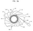
- FIG. 3 ashows tension applied to a polymeric sheet while the wrapped stent is being compressed.
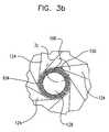
- FIG. 3 bshows a sheath and a stent in a crimper having a blade with a sacrificial tip.
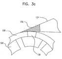
- FIG. 3 cshows an enlargement of region 3 c of FIG. 3 b.
- FIG. 4shows formation of a sheath
- FIG. 5shows a stent delivery device
- FIG. 6 ashows a stent delivery device
- FIG. 6 bshows an enlarged portion of the stent delivery device of FIG. 6 a.
- the inventionis directed to a method comprising the steps of providing a wrapped stent, compressing the wrapped stent and forming a sheath about the stent.
- the wrapped stentas shown at 100 in FIG. 1 , comprises stent 104 with polymeric sheet 108 disposed thereabout.
- Sheet 108has two opposing edges 112 and 116 extending along at least a portion of the length of stent 104 . Desirably, as shown in FIG. 1 , the two opposing edges extend along the entire length of the stent.
- stent 104will be a self-expanding stent. More desirably, stent 104 will be a coated self-expanding stent. The invention may also be practiced with balloon expandable stents, both bare and coated.
- the sheathwill desirably be made of any material strong enough to contain a compressed stent and flexible enough to be tracked on a delivery system in the body. Desirably, it will be such that it can be thermally attached to itself or tie layers.
- Suitable polymeric materialsinclude known sheath materials such as those disclosed in U.S. Pat. No. 5,968,069 and U.S. Pat. No. 6,068,634. Examples of sheath materials include elastomers such as polyurethane, polyurethane blends, silicone, latex or polyether amide. Sheath materials may include thermoplastics including polyethylene, polypropylene, polyamide, polyimide, polyesters (polyethylene terephthalate) and polyethylene naphthalate.
- the stentwill be compressed with a compression device such as an iris-type crimper shown generally in cross-section at 120 .
- Compression device 120includes a plurality of blades 124 disposed about an opening 128 . The blades can be moved inward to apply an inward force to the stent so as to compress the stent.
- Other types of compression devicesmay also be used in the practice of the invention as discussed below.
- wrapped stent 100is disposed in a compression device. At least one of the opposing edges of the sheet is pulled, as shown in FIG.
- both of the opposing edges of the sheetare pulled while applying or after applying a compressive force to the stent so as to tighten the polymeric sheet about the stent.
- Device 132places the edge of the sheet under tension.
- the polymeric sheetis wrapped more tightly around the stent and some slack is removed from the sheet.
- the polymeric sheetwill be wrapped as tightly as is needed to bring the stent down to and maintain a fully compressed state in which adjacent struts will typically be touching one another or nearly touching.
- any compression devicemay be used. Examples of such devices include that disclosed in U.S. Pat. No. 6,360,577 and that disclosed in US 20020138966.
- the devicewill be of the iris type, comprising a plurality of blades which are disposed about an opening and which can open and close in an iris-like manner.
- Other compression devicesmay also be used in the practice of the invention.
- sheath 136is formed about stent 104 by affixing at least one of the opposing edges of the polymeric sheet to a portion of the polymeric sheet adjacent thereto. If necessary, excess polymeric material may be trimmed from the polymeric sheet prior to the affixing step, or from the sheath following the affixing step.
- a seam, shown at 140may be visible on the wrapped stent following the affixing step.
- the sheathis disposed about the stent but is not affixed thereto and can be removed from the stent at later time by sliding the sheath off of the stent or by pulling the stent from the sheath.
- each opposing edge 112 , 116may be affixed to a portion of the polymeric sheet adjacent thereto.
- the polymeric sheetmay be properly sized such that when the stent is in a fully compressed state, the opposing edges 112 , 116 of the polymeric sheet may be affixed to one another or affixed while arranged in a slightly overlapping relationship.
- An edge of the polymeric sheetmay be attached to an adjacent portion of the polymeric sheet so to form the sheath in a variety of different ways.
- An example of a suitable methodincludes adhesively affixing one of the edges to the polymeric sheet using a pressure sensitive adhesive, a one part adhesive, a two part adhesive or any other suitable type of adhesive.
- Suitable adhesivesinclude, but are not limited to, liquid adhesives and pressure sensitive adhesives.
- Suitable adhesives materials for useinclude, but are not limited to one part adhesives—silicone room temperature vulcanization adhesives (RTVs), one part heat cured polyurethanes (air, heat and moisture cured), epoxies, acrylics, cyanoacrylics, methacrylics, epoxypolyurethanes (including anerobic one part adhesives, one part water-based adhesives), two-part adhesives—epoxies, urethane epoxies, urethane, urethane, polysulfides, urethane liquid moisture cure, pressure sensitive adhesives, polymerizable adhesives (including cyanoacrylates), resins (including aliphatic resins), polyurethane, polyvinyl acetate, contact cements, and hide glues, UV curable adhesives, hot melt adhesives, double-sided tape—containing acrylic and acrylic-epoxy adhesives.
- RTVsroom temperature vulcanization adhesives
- epoxiesacrylics,
- the compression devicemay comprise at least one heated blade 144 which is used to contact weld the edge in place.
- the compression devicemay comprise at least one sacrificial blade.
- the sacrificial blademay be in the form of blade 124 which has at its tip a sacrificial material 156 .
- the sacrificial blademay optionally be heated.
- the sacrificial materialmay be used to fill in any gap, as shown at 158 in FIG. 3 c , in the sheath, for example, between the edges of the sheath. This may be accomplished by fusing the sacrificial material to the sheath.
- the sacrificial materialwill desirably be thermally compatible with the sheath and/or compatible with the sheath from a bonding perspective.
- FIG. 6 bshows an enlarged view of detail A of the distal end of the stent delivery device of FIG. 6 a .
- the sheathmay be attached, using standard joining processes including, but not limited to adhesive bonding, RF bonding and laser bonding or via any other suitable technique, to a sheath withdrawal device.
- the sheath withdrawal deviceis in the form of a movable tube 160 .
- the sheath withdrawal devicemay be in the form of a pull wire or any other suitable device.
- the stent delivery deviceshould be suitable for the type of stent to be delivered.
- a catheterconfigured for delivering self-expanding stents or other medical devices will be used.
- Such a catheterwill desirably have a device which can be attached to the sheath to remove the sheath from the stent at the appropriate time. This may be accomplished in a number of ways including by attaching a pull wire 155 to the sheath.
- Cathetersare well known in the art and catheters such as those disclosed in U.S. Pat. No. 5,772,669 and U.S. Pat. No. 6,120,522 may be modified for use in the present invention.
- the methodmay further comprise the steps of inserting the stent delivery catheter or more generally, the medical device delivery catheter in a bodily vessel, delivering the stent or medical device to a desired bodily location, withdrawing the sheath from the stent or medical device and expanding the stent or medical device. The sheath may then be withdrawn from the body.
- a typical balloon cathetermay be used.
- the balloon catheterwill have to be suitably modified, however, to allow for easy removal of the sheath from the stent or other medical device after it has been disposed about the balloon or other expandable member of the catheter.
- the use of the inventive methods disclosed herein in conjunction with balloon expandable stentsmay be of particular value in conjunction with drug coated stents.
- the inventionis also directed to any of the inventive methods disclosed herein in which drug coated stents, balloon expandable or mechanically expandable, are used.
- the stents used in the practice of the inventive, or more generally, the implantable medical devicesmay also be a hybrid device, being both balloon expandable in-part and self-expanding in-part.
- the sheathwill have seam which extends parallel to the longitudinal axis of the stent or medical device. It is also within the scope of the invention for the resulting seam to be non-parallel to the longitudinal axis of the stent or medical device.
- the sheathmay be wrapped spirally about the medical device so as to have a spiral seam.
- Other shaped seamsare also within the scope of the invention. The seam need not be continuous and may be interrupted.
- the inventionis also directed to a method of securing a medical device to a medical device delivery apparatus.
- the methodcomprises the steps of providing a wrapped medical device, compressing the wrapped medical device and forming a sheathed medical device from the compressed medical device.
- the wrapped medical devicecomprises a medical device with a polymeric sheet disposed thereabout.
- the sheethas two opposing edges extending along at least a portion of the length of the medical device. At least one of the opposing edges is affixed to a portion of the polymeric sheet adjacent thereto so as to form a sheathed medical device, the polymeric sheet forming a sheath about the medical device.
- the compressing stepmay include the steps of disposing the wrapped medical device in a compression device and pulling on at least one of the opposing edges of the sheet while applying or after applying a compressive force to the medical device so as to tighten the polymeric sheet about the medical device.
- a seamis visible on the wrapped medical device.
- the securing stepmay include attaching the sheathed medical device to a sheath removal mechanism which is operatively associated with the medical device delivery apparatus such that the medical device, after the securing step, may be removed from the sheath upon activation of the sheath removal mechanism.
- the methodmay further comprise the steps of providing a medical device delivery apparatus and securing the sheathed medical device to the medical device delivery apparatus.
- the medical devicewill be a stent, a filter or an embolic protection device.
- the stentwill desirably be self-expanding.
- Suitable filtersinclude vena cava filters.
- Medical device delivery catheter 150includes a catheter tube 190 with a sheathed medical device 100 disposed thereabout.
- Sheathed medical device 100includes a medical device such as a stent, desirably self-expanding, a filter or an embolic protection device, and a sheath disposed thereabout, the sheath having a seam.
- the inventionis further directed to a compression device comprising at least one sacrificial blade which may be fused to the polymeric sheet.
- a compression devicecomprising at least one sacrificial blade which may be fused to the polymeric sheet.
- FIG. 3 cAn example of such a device is shown in FIG. 3 c , wherein a blade 124 is shown having a sacrificial tip 156 .
- the sacrificial blademay be located on the tip of a loading blade, located where the joining occurs. Thus, for example, it may be located at the location of a seam.
- the sacrificial materialwould be compatible with the sheath material and would be suitable for the process used to join the sheath into a tubular configuration.
- the inventionis also directed to a medical device which is provided with a sheath using any of the inventive methods disclosed herein.
- the inventionis directed to a sheathed medical device wherein the sheath has a seam.
- the seammay be parallel to longitudinal axis of the medical device, may spiral about the longitudinal axis or may assume some other configuration.
- the medical devicemay be any of those disclosed herein including, but not limited to stents.
- the inventionis also directed to a medical delivery device comprising any of the sheathed medical devices disclosed herein and a catheter.
- the stents and other medical devices to be sheathed in the practice of the inventionmay be of any suitable design and material including polymeric materials, metals, ceramics and composites.
- Suitable polymeric materialsinclude but are not limited to thermo tropic liquid crystal polymers (Lip's).
- Suitable metalsinclude but are not limited to stainless steel, cobalt chrome alloys such as edgily, tantalum or other plastically deformable metals.
- Other suitable metalsinclude but are not limited to shape-memory metals such as nickel titanium alloys generically known as “nitinol”, platinum/tungsten alloys and titanium alloys.
- the stents and other medical devicesmay include suitable radiopaque coatings.
- theymay be coated with gold or other noble metals or sputtered with tantalum or other metals. They may also be made directly from a radiopaque material to obviate the need for a radiopaque coating or may be made of a material having a radiopaque inner core.
- Other radiopaque metals which may be usedinclude platinum, platinum tungsten, palladium, platinum iridium, rhodium, tantalum, or alloys or composites of these metals.
- the coatingmay comprise one or more non-genetic therapeutic agents, genetic materials and cells and combinations thereof as well as other polymeric coatings.
- Non-genetic therapeutic agentsinclude anti-thrombogenic agents such as heparin, heparin derivatives, urokinase, and PPack (dextrophenylalanine proline arginine chloromethylketone); anti-proliferative agents such as enoxaprin, angiopeptin, or monoclonal antibodies capable of blocking smooth muscle cell proliferation, hirudin, and acetylsalicylic acid; anti-inflammatory agents such as dexamethasone, prednisolone, corticosterone, budesonide, estrogen, sulfasalazine, and mesalamine; antineoplastic/antiproliferative/anti-miotic agents such as paclitaxel, 5-fluorouracil, cisplatin, vinblastine, vincristine, epothilones, endostatin, angiostatin and thymidine kinase inhibitors; anesthetic agents such as lidocaine, b
- Genetic materialsinclude anti-sense DNA and RNA, DNA coding for, anti-sense RNA, tRNA or rRNA to replace defective or deficient endogenous molecules, angiogenic factors including growth factors such as acidic and basic fibroblast growth factors, vascular endothelial growth factor, epidermal growth factor, transforming growth factor alpha.
- platelet-derived endothelial growth factorplatelet-derived growth factor
- platelet-derived growth factortumor necrosis factor alpha.
- hepatocyte growth factor and insulin like growth factorcell cycle inhibitors including CD inhibitors, thymidine kinase (“TK”) and other agents useful for interfering with cell proliferation the family of bone morphogenic proteins (“BMP's”),BMP-2, BMP-3, BMP-4, BMP-5, BMP-6 (Vgr-1), BMP-7 (OP-1), BMP-8, BMP-9, BMP-10, BMP-11, BMP-12, BMP-13, BMP-14, BMP-15, and BMP-16.
- BMP'sbone morphogenic proteins
- Desirable BMP'sare any of BMP-2, BMP-3, BMP-4, BMP-5, BMP-6 and BMP-7. These dimeric proteins can be provided as homodimers, heterodimers, or combinations thereof, alone or together with other molecules. Alternatively or, in addition, molecules capable of inducing an upstream or downstream effect of a BMP can be provided. Such molecules include any of the “hedgehog” proteins, or the DNA's encoding them.
- Cellscan be of human origin (autologous or allogeneic) or from an animal source (xenogeneic), genetically engineered if desired to deliver proteins of interest at the transplant site.
- the cellsmay be provided in a delivery media.
- the delivery mediamay be formulated as needed to maintain cell function and viability.
- Suitable polymer coating materialsinclude polycarboxylic acids, cellulosic polymers, including cellulose acetate and cellulose nitrate, gelatin, polyvinylpyrrolidone, cross-linked polyvinylpyrrolidone, polyanhydrides including maleic anhydride polymers, polyamides, polyvinyl alcohols, copolymers of vinyl monomers such as EVA, polyvinyl ethers, polyvinyl aromatics, polyethylene oxides, glycosaminoglycans, polysaccharides, polyesters including polyethylene terephthalate, polyacrylamides, polyethers, polyether sulfone, polycarbonate, polyalkylenes including polypropylene, polyethylene and high molecular weight polyethylene, halogenated polyalkylenes including polytetrafluoroethylene, polyurethanes, polyorthoesters, proteins, polypeptides, silicones, siloxane polymers, polylactic acid, polyglycolic acid, polycaprolactone
- Polyacrylic acidavailable as HYDROPLUSTM (Boston Scientific Corporation, Natick, Mass.), and described in U.S. Pat. No. 5,091,205, the disclosure of which is hereby incorporated herein by reference, is particularly desirable. Even more desirable is a copolymer of polylactic acid and polycaprolactone.
- the stents and other medical devices to be sheathedmay also be used as the framework for a graft.
- Suitable coveringsinclude nylon, collagen, PTFE and expanded PTFE, polyethylene terephthalate and KEVLAR, or any of the materials disclosed in U.S. Pat. No. 5,824,046 and U.S. Pat. No. 5,755,770.
- any known graft materialmay be used including synthetic polymers such as polyethylene, polypropylene, polyurethane, polyglycolic acid, polyesters, polyamides, their mixtures, blends, copolymers, mixtures, blends and copolymers.
- the medical devices to be sheathedmay include expandable frameworks, regardless of whether they are capable of maintaining the patency of a vessel.
- the stents and other medical devices to be sheathedmay find use in coronary arteries, renal arteries, peripheral arteries including iliac arteries, arteries of the neck and cerebral arteries. They are not, however, limited to use in the vascular system and may also be advantageously employed in other body structures, including but not limited to arteries, veins, biliary ducts, urethras, fallopian tubes, bronchial tubes, the trachea, the esophagus and the prostate.
Landscapes
- Health & Medical Sciences (AREA)
- Engineering & Computer Science (AREA)
- Biomedical Technology (AREA)
- Life Sciences & Earth Sciences (AREA)
- Oral & Maxillofacial Surgery (AREA)
- Transplantation (AREA)
- Heart & Thoracic Surgery (AREA)
- Vascular Medicine (AREA)
- Cardiology (AREA)
- Animal Behavior & Ethology (AREA)
- General Health & Medical Sciences (AREA)
- Public Health (AREA)
- Veterinary Medicine (AREA)
- Media Introduction/Drainage Providing Device (AREA)
- Materials For Medical Uses (AREA)
- Prostheses (AREA)
Abstract
Description
Claims (24)
Priority Applications (2)
| Application Number | Priority Date | Filing Date | Title |
|---|---|---|---|
| US10/917,780US7765670B2 (en) | 2004-08-13 | 2004-08-13 | Method to simultaneously load and cover self expanding stents |
| PCT/US2005/028420WO2006017849A2 (en) | 2004-08-13 | 2005-08-10 | Method to simultaneously load and cover self-expanding stents |
Applications Claiming Priority (1)
| Application Number | Priority Date | Filing Date | Title |
|---|---|---|---|
| US10/917,780US7765670B2 (en) | 2004-08-13 | 2004-08-13 | Method to simultaneously load and cover self expanding stents |
Publications (2)
| Publication Number | Publication Date |
|---|---|
| US20060036310A1 US20060036310A1 (en) | 2006-02-16 |
| US7765670B2true US7765670B2 (en) | 2010-08-03 |
Family
ID=35517547
Family Applications (1)
| Application Number | Title | Priority Date | Filing Date |
|---|---|---|---|
| US10/917,780Expired - Fee RelatedUS7765670B2 (en) | 2004-08-13 | 2004-08-13 | Method to simultaneously load and cover self expanding stents |
Country Status (2)
| Country | Link |
|---|---|
| US (1) | US7765670B2 (en) |
| WO (1) | WO2006017849A2 (en) |
Cited By (5)
| Publication number | Priority date | Publication date | Assignee | Title |
|---|---|---|---|---|
| US20060216404A1 (en)* | 2004-11-02 | 2006-09-28 | Seyler Paul R | Stent sheathing technology |
| US20110251663A1 (en)* | 2010-04-07 | 2011-10-13 | Medtronic Vascular, Inc. | Drug Eluting Rolled Stent and Stent Delivery System |
| US20120110809A1 (en)* | 2009-01-20 | 2012-05-10 | Abbott Laboratories Vascular Enterprises Limited | Stent crimping device |
| US10433993B2 (en)* | 2017-01-20 | 2019-10-08 | Medtronic Vascular, Inc. | Valve prosthesis having a radially-expandable sleeve integrated thereon for delivery and prevention of paravalvular leakage |
| US20220008235A1 (en)* | 2018-11-27 | 2022-01-13 | Biotronik Ag | Process for machine pre-crimping of stents, especially drug-coated stents |
Families Citing this family (12)
| Publication number | Priority date | Publication date | Assignee | Title |
|---|---|---|---|---|
| US20060100689A1 (en)* | 2004-11-10 | 2006-05-11 | Medtronic Vascular, Inc. | Stent crimper with slit sheath |
| US7316148B2 (en)* | 2005-02-15 | 2008-01-08 | Boston Scientific Scimed, Inc. | Protective sheet loader |
| US8225474B2 (en)* | 2008-05-30 | 2012-07-24 | Boston Scientific Scimed, Inc. | Stent crimping device |
| US20110184509A1 (en)* | 2010-01-27 | 2011-07-28 | Abbott Laboratories | Dual sheath assembly and method of use |
| US20110208292A1 (en)* | 2010-02-19 | 2011-08-25 | Abbott Laboratories | Hinged sheath assembly and method of use |
| US10111767B2 (en)* | 2010-10-29 | 2018-10-30 | Abbott Cardiovascular Systems Inc. | Sheaths used in polymer scaffold delivery systems |
| US9414944B2 (en)* | 2010-11-11 | 2016-08-16 | W. L. Gore & Associates, Inc. | Deployment sleeve shortening mechanism |
| US8414528B2 (en) | 2011-05-27 | 2013-04-09 | Abbott Cardiovascular Systems Inc. | Polymer scaffold sheaths |
| US8852257B2 (en) | 2011-06-21 | 2014-10-07 | Abbott Cardiovascular Systems Inc. | Sheaths used with polymer scaffold |
| US9364361B2 (en) | 2014-03-13 | 2016-06-14 | Abbott Cardiovascular Systems Inc. | Striped sheaths for medical devices |
| CN108295359B (en)* | 2016-12-30 | 2021-05-07 | 先健科技(深圳)有限公司 | Drug-loaded device and preparation method thereof |
| US20180236205A1 (en)* | 2017-02-23 | 2018-08-23 | Boston Scientific Scimed, Inc. | Loading tools for use with medical devices |
Citations (72)
| Publication number | Priority date | Publication date | Assignee | Title |
|---|---|---|---|---|
| US3490136A (en)* | 1965-05-05 | 1970-01-20 | Gen Electric | Method of assembling one object within another |
| US3509617A (en)* | 1968-02-28 | 1970-05-05 | Olin Mathieson | Cylindrical or rod-like composite article |
| US4489473A (en)* | 1981-04-17 | 1984-12-25 | Isolite Babcock Refractories, Co., Ltd. | Method for installing thermal insulation materials on the inner surface of a duct |
| US5091205A (en) | 1989-01-17 | 1992-02-25 | Union Carbide Chemicals & Plastics Technology Corporation | Hydrophilic lubricious coatings |
| US5261263A (en)* | 1992-12-21 | 1993-11-16 | Whitesell Eric J | Crimping pliers with radially opposed jaws |
| US5443458A (en)* | 1992-12-22 | 1995-08-22 | Advanced Cardiovascular Systems, Inc. | Multilayered biodegradable stent and method of manufacture |
| EP0716836A1 (en) | 1994-12-13 | 1996-06-19 | Advanced Cardiovascular Systems, Inc. | Polymer film for wrapping a stent structure |
| US5690644A (en) | 1992-12-30 | 1997-11-25 | Schneider (Usa) Inc. | Apparatus for deploying body implantable stent |
| US5718973A (en)* | 1993-08-18 | 1998-02-17 | W. L. Gore & Associates, Inc. | Tubular intraluminal graft |
| US5725519A (en)* | 1996-09-30 | 1998-03-10 | Medtronic Instent Israel Ltd. | Stent loading device for a balloon catheter |
| US5755770A (en) | 1995-01-31 | 1998-05-26 | Boston Scientific Corporatiion | Endovascular aortic graft |
| US5772669A (en) | 1996-09-27 | 1998-06-30 | Scimed Life Systems, Inc. | Stent deployment catheter with retractable sheath |
| US5824046A (en)* | 1996-09-27 | 1998-10-20 | Scimed Life Systems, Inc. | Covered stent |
| US5836952A (en)* | 1996-08-21 | 1998-11-17 | Cordis Corporation | Hand-held stent crimper |
| US5906759A (en)* | 1996-12-26 | 1999-05-25 | Medinol Ltd. | Stent forming apparatus with stent deforming blades |
| US5920975A (en)* | 1997-11-03 | 1999-07-13 | Advanced Cardiovascular Systems, Inc. | Stent crimping tool and method of use |
| US5928279A (en)* | 1996-07-03 | 1999-07-27 | Baxter International Inc. | Stented, radially expandable, tubular PTFE grafts |
| US5948191A (en) | 1996-07-15 | 1999-09-07 | Cordis Corporation | Low profile, thermally set wrapped cover for a percutaneously deployed stent |
| US5968069A (en) | 1996-08-23 | 1999-10-19 | Scimed Life Systems, Inc. | Stent delivery system having stent securement apparatus |
| US5992000A (en)* | 1997-10-16 | 1999-11-30 | Scimed Life Systems, Inc. | Stent crimper |
| US6004328A (en) | 1997-06-19 | 1999-12-21 | Solar; Ronald J. | Radially expandable intraluminal stent and delivery catheter therefore and method of using the same |
| US6009614A (en)* | 1998-04-21 | 2000-01-04 | Advanced Cardiovascular Systems, Inc. | Stent crimping tool and method of use |
| US6063092A (en) | 1998-04-07 | 2000-05-16 | Medtronic Inc. | Heat set and crimping process to optimize stent retention |
| US6068634A (en) | 1996-08-23 | 2000-05-30 | Scimed Life Systems, Inc. | Stent delivery system |
| US6082990A (en)* | 1998-02-17 | 2000-07-04 | Advanced Cardiovascular Systems, Inc. | Stent crimping tool |
| US6096027A (en)* | 1998-09-30 | 2000-08-01 | Impra, Inc., A Subsidiary Of C.R. Bard, Inc. | Bag enclosed stent loading apparatus |
| US6120522A (en) | 1998-08-27 | 2000-09-19 | Scimed Life Systems, Inc. | Self-expanding stent delivery catheter |
| US6141855A (en)* | 1998-04-28 | 2000-11-07 | Advanced Cardiovascular Systems, Inc. | Stent crimping tool and method of use |
| US20010001890A1 (en)* | 1999-09-22 | 2001-05-31 | Michael Austin | Method for contracting, loading or crimping self-expanding and balloon expandable stent devices |
| US6290722B1 (en)* | 2000-03-13 | 2001-09-18 | Endovascular Technologies, Inc. | Tacky attachment method of covered materials on stents |
| US6302893B1 (en) | 1996-07-15 | 2001-10-16 | Advanced Cardiovascular Systems, Inc. | Self-expanding stent delivery system |
| US6309383B1 (en)* | 2000-01-20 | 2001-10-30 | Isostent, Inc. | Stent crimper apparatus with radiation shied |
| US6387117B1 (en)* | 1999-09-22 | 2002-05-14 | Scimed Life Systems, Inc. | Stent crimping system |
| US6416536B1 (en) | 1999-06-21 | 2002-07-09 | Scimed Life Systems, Inc. | Method for deployment of a low profile delivery system |
| US20020099431A1 (en) | 2001-01-22 | 2002-07-25 | Armstrong Joseph R. | Deployment system for intraluminal devices |
| US6432130B1 (en)* | 2000-04-20 | 2002-08-13 | Scimed Life Systems, Inc. | Fully sheathed balloon expandable stent delivery system |
| US6443979B1 (en) | 1999-12-20 | 2002-09-03 | Advanced Cardiovascular Systems, Inc. | Expandable stent delivery sheath and method of use |
| US20020138129A1 (en)* | 1999-01-22 | 2002-09-26 | Armstrong Joseph R. | Method of producing low profile stent and graft combination |
| US20020138966A1 (en)* | 2000-06-08 | 2002-10-03 | Tom Motsenbocker | Stent crimping apparatus and method |
| US20020161394A1 (en)* | 1997-09-26 | 2002-10-31 | Macoviak John A. | Aortic filter catheter |
| US20020163104A1 (en)* | 2001-03-26 | 2002-11-07 | Tom Motsenbocker | Balloon folding technology |
| US20020198588A1 (en)* | 1999-01-22 | 2002-12-26 | Armstrong Joseph R. | Covered endoprosthesis and delivery system |
| US6510722B1 (en)* | 2000-05-10 | 2003-01-28 | Advanced Cardiovascular Systems, Inc. | Stent crimping tool for producing a grooved crimp |
| US20030028237A1 (en) | 1999-10-01 | 2003-02-06 | Jason Sullivan | Medical device retaining sheath and medical device delivery system employing same |
| US20030056360A1 (en)* | 1997-10-16 | 2003-03-27 | Terry V. Brown | Radial stent crimper |
| US6540776B2 (en) | 2000-12-28 | 2003-04-01 | Advanced Cardiovascular Systems, Inc. | Sheath for a prosthesis and methods of forming the same |
| US20030070469A1 (en)* | 2000-08-10 | 2003-04-17 | Arkady Kokish | Assembly for crimping an intraluminal device or measuring the radial strength of the intraluminal device and method of use |
| US20030074049A1 (en)* | 2000-08-25 | 2003-04-17 | Kensey Nash Corporation | Covered stents and systems for deploying covered stents |
| US6568235B1 (en)* | 2000-08-10 | 2003-05-27 | Advanced Cardiovascular Systems, Inc. | Assembly for crimping an intraluminal device or measuring the radial strength of the intraluminal device and method of use |
| US20030099792A1 (en)* | 1999-12-11 | 2003-05-29 | Gunnar Andersson | Multi-layer film and method of making same |
| US6576005B1 (en)* | 1998-04-23 | 2003-06-10 | Boston Scientific Corporation | Stent deployment device and method for deploying a stent |
| US20030113499A1 (en)* | 2000-06-27 | 2003-06-19 | Reto Sieber | Industrial adhesive tape for improved sealing of joints and an industrial adhesive tape dispenser |
| US6629992B2 (en) | 2000-08-04 | 2003-10-07 | Advanced Cardiovascular Systems, Inc. | Sheath for self-expanding stent |
| US6640412B2 (en)* | 2001-04-26 | 2003-11-04 | Endovascular Technologies, Inc. | Method for loading a stent using a collapsing machine |
| US6666880B1 (en)* | 2001-06-19 | 2003-12-23 | Advised Cardiovascular Systems, Inc. | Method and system for securing a coated stent to a balloon catheter |
| US6702845B1 (en)* | 2003-01-17 | 2004-03-09 | Gore Enterprise Holdings, Inc. | Compacted implantable medical devices and method of compacting such devices |
| US20040123437A1 (en)* | 2002-12-26 | 2004-07-01 | Arkady Kokish | Assembly for crimping an intraluminal device and method of use |
| US20040128818A1 (en)* | 2002-08-31 | 2004-07-08 | Thomas Motsenbocker | Hand held stent crimping apparatus and method |
| US20040148007A1 (en) | 2003-01-23 | 2004-07-29 | Jackson Karen Paulette | Friction reducing lubricant for stent loading and stent delivery systems |
| US20040167603A1 (en)* | 2003-02-20 | 2004-08-26 | Jackson Karen Paulette | Friction reducing agent for loading a self-expanding stent |
| US20040181236A1 (en)* | 2003-03-12 | 2004-09-16 | Eidenschink Thomas C. | Methods of making medical devices |
| US6800089B1 (en)* | 2000-05-31 | 2004-10-05 | Advanced Cardiovascular Systems, Inc. | Mechanical attachment method of cover materials on stents |
| US20040199239A1 (en)* | 2003-04-04 | 2004-10-07 | Michael Austin | Protective loading of stents |
| US6808533B1 (en)* | 2000-07-28 | 2004-10-26 | Atrium Medical Corporation | Covered stent and method of covering a stent |
| US20040260379A1 (en)* | 2003-06-23 | 2004-12-23 | Jagger Karl A. | Asymmetric stent delivery system with proximal edge protection and method of manufacture thereof |
| US6865810B2 (en)* | 2002-06-27 | 2005-03-15 | Scimed Life Systems, Inc. | Methods of making medical devices |
| US20050183259A1 (en)* | 2004-02-23 | 2005-08-25 | Tracee Eidenschink | Apparatus and method for crimping a stent assembly |
| US7207204B2 (en)* | 2004-02-26 | 2007-04-24 | Boston Scientific Scimed, Inc. | Crimper |
| US20080028594A1 (en)* | 2005-04-29 | 2008-02-07 | Arterial Remodelling Technologies, Inc. | Stent Crimping |
| US20090113693A1 (en)* | 2007-11-05 | 2009-05-07 | Cook Incorporated | Apparatus and method for compressing a stent |
| US7636998B2 (en)* | 2003-12-29 | 2009-12-29 | Ethicon, Inc. | Urethral stent reducer |
| US7636997B2 (en)* | 2004-01-29 | 2009-12-29 | Boston Scientific Scimed, Inc. | Method for crimping and loading of intraluminal medical devices |
- 2004
- 2004-08-13USUS10/917,780patent/US7765670B2/ennot_activeExpired - Fee Related
- 2005
- 2005-08-10WOPCT/US2005/028420patent/WO2006017849A2/enactiveApplication Filing
Patent Citations (92)
| Publication number | Priority date | Publication date | Assignee | Title |
|---|---|---|---|---|
| US3490136A (en)* | 1965-05-05 | 1970-01-20 | Gen Electric | Method of assembling one object within another |
| US3509617A (en)* | 1968-02-28 | 1970-05-05 | Olin Mathieson | Cylindrical or rod-like composite article |
| US4489473A (en)* | 1981-04-17 | 1984-12-25 | Isolite Babcock Refractories, Co., Ltd. | Method for installing thermal insulation materials on the inner surface of a duct |
| US5091205A (en) | 1989-01-17 | 1992-02-25 | Union Carbide Chemicals & Plastics Technology Corporation | Hydrophilic lubricious coatings |
| US5261263A (en)* | 1992-12-21 | 1993-11-16 | Whitesell Eric J | Crimping pliers with radially opposed jaws |
| US5443458A (en)* | 1992-12-22 | 1995-08-22 | Advanced Cardiovascular Systems, Inc. | Multilayered biodegradable stent and method of manufacture |
| US5690644A (en) | 1992-12-30 | 1997-11-25 | Schneider (Usa) Inc. | Apparatus for deploying body implantable stent |
| US5718973A (en)* | 1993-08-18 | 1998-02-17 | W. L. Gore & Associates, Inc. | Tubular intraluminal graft |
| US5700286A (en)* | 1994-12-13 | 1997-12-23 | Advanced Cardiovascular Systems, Inc. | Polymer film for wrapping a stent structure |
| EP0716836A1 (en) | 1994-12-13 | 1996-06-19 | Advanced Cardiovascular Systems, Inc. | Polymer film for wrapping a stent structure |
| US5637113A (en)* | 1994-12-13 | 1997-06-10 | Advanced Cardiovascular Systems, Inc. | Polymer film for wrapping a stent structure |
| US5755770A (en) | 1995-01-31 | 1998-05-26 | Boston Scientific Corporatiion | Endovascular aortic graft |
| US5928279A (en)* | 1996-07-03 | 1999-07-27 | Baxter International Inc. | Stented, radially expandable, tubular PTFE grafts |
| US5948191A (en) | 1996-07-15 | 1999-09-07 | Cordis Corporation | Low profile, thermally set wrapped cover for a percutaneously deployed stent |
| US6302893B1 (en) | 1996-07-15 | 2001-10-16 | Advanced Cardiovascular Systems, Inc. | Self-expanding stent delivery system |
| US6576006B2 (en) | 1996-07-15 | 2003-06-10 | Advanced Cardiovascular Systems, Inc. | Self-expanding stent delivery system |
| US5836952A (en)* | 1996-08-21 | 1998-11-17 | Cordis Corporation | Hand-held stent crimper |
| US6068634A (en) | 1996-08-23 | 2000-05-30 | Scimed Life Systems, Inc. | Stent delivery system |
| US5968069A (en) | 1996-08-23 | 1999-10-19 | Scimed Life Systems, Inc. | Stent delivery system having stent securement apparatus |
| US5824046A (en)* | 1996-09-27 | 1998-10-20 | Scimed Life Systems, Inc. | Covered stent |
| US5772669A (en) | 1996-09-27 | 1998-06-30 | Scimed Life Systems, Inc. | Stent deployment catheter with retractable sheath |
| US5725519A (en)* | 1996-09-30 | 1998-03-10 | Medtronic Instent Israel Ltd. | Stent loading device for a balloon catheter |
| US5906759A (en)* | 1996-12-26 | 1999-05-25 | Medinol Ltd. | Stent forming apparatus with stent deforming blades |
| US6004328A (en) | 1997-06-19 | 1999-12-21 | Solar; Ronald J. | Radially expandable intraluminal stent and delivery catheter therefore and method of using the same |
| US20020161394A1 (en)* | 1997-09-26 | 2002-10-31 | Macoviak John A. | Aortic filter catheter |
| US6769161B2 (en)* | 1997-10-16 | 2004-08-03 | Scimed Life Systems, Inc. | Radial stent crimper |
| US20030056360A1 (en)* | 1997-10-16 | 2003-03-27 | Terry V. Brown | Radial stent crimper |
| US5992000A (en)* | 1997-10-16 | 1999-11-30 | Scimed Life Systems, Inc. | Stent crimper |
| US5920975A (en)* | 1997-11-03 | 1999-07-13 | Advanced Cardiovascular Systems, Inc. | Stent crimping tool and method of use |
| US6082990A (en)* | 1998-02-17 | 2000-07-04 | Advanced Cardiovascular Systems, Inc. | Stent crimping tool |
| US6063092A (en) | 1998-04-07 | 2000-05-16 | Medtronic Inc. | Heat set and crimping process to optimize stent retention |
| US6009614A (en)* | 1998-04-21 | 2000-01-04 | Advanced Cardiovascular Systems, Inc. | Stent crimping tool and method of use |
| US6576005B1 (en)* | 1998-04-23 | 2003-06-10 | Boston Scientific Corporation | Stent deployment device and method for deploying a stent |
| US6141855A (en)* | 1998-04-28 | 2000-11-07 | Advanced Cardiovascular Systems, Inc. | Stent crimping tool and method of use |
| US6120522A (en) | 1998-08-27 | 2000-09-19 | Scimed Life Systems, Inc. | Self-expanding stent delivery catheter |
| US6096027A (en)* | 1998-09-30 | 2000-08-01 | Impra, Inc., A Subsidiary Of C.R. Bard, Inc. | Bag enclosed stent loading apparatus |
| US20020138129A1 (en)* | 1999-01-22 | 2002-09-26 | Armstrong Joseph R. | Method of producing low profile stent and graft combination |
| US20020198588A1 (en)* | 1999-01-22 | 2002-12-26 | Armstrong Joseph R. | Covered endoprosthesis and delivery system |
| US6416536B1 (en) | 1999-06-21 | 2002-07-09 | Scimed Life Systems, Inc. | Method for deployment of a low profile delivery system |
| US6360577B2 (en)* | 1999-09-22 | 2002-03-26 | Scimed Life Systems, Inc. | Apparatus for contracting, or crimping stents |
| US6387117B1 (en)* | 1999-09-22 | 2002-05-14 | Scimed Life Systems, Inc. | Stent crimping system |
| US6823576B2 (en)* | 1999-09-22 | 2004-11-30 | Scimed Life Systems, Inc. | Method and apparatus for contracting, loading or crimping self-expanding and balloon expandable stent devices |
| US20030192164A1 (en)* | 1999-09-22 | 2003-10-16 | Scimed Life Systems, Inc. | Method and apparatus for contracting, loading or crimping self-expanding and balloon expandable stent devices |
| US6915560B2 (en)* | 1999-09-22 | 2005-07-12 | Boston Scientific Scimed, Inc. | Apparatus for contracting, loading or crimping self-expanding and balloon expandable stent devices |
| US20010001890A1 (en)* | 1999-09-22 | 2001-05-31 | Michael Austin | Method for contracting, loading or crimping self-expanding and balloon expandable stent devices |
| US6533806B1 (en) | 1999-10-01 | 2003-03-18 | Scimed Life Systems, Inc. | Balloon yielded delivery system and endovascular graft design for easy deployment |
| US20030028237A1 (en) | 1999-10-01 | 2003-02-06 | Jason Sullivan | Medical device retaining sheath and medical device delivery system employing same |
| US20030099792A1 (en)* | 1999-12-11 | 2003-05-29 | Gunnar Andersson | Multi-layer film and method of making same |
| US6443979B1 (en) | 1999-12-20 | 2002-09-03 | Advanced Cardiovascular Systems, Inc. | Expandable stent delivery sheath and method of use |
| US6309383B1 (en)* | 2000-01-20 | 2001-10-30 | Isostent, Inc. | Stent crimper apparatus with radiation shied |
| US6290722B1 (en)* | 2000-03-13 | 2001-09-18 | Endovascular Technologies, Inc. | Tacky attachment method of covered materials on stents |
| US6432130B1 (en)* | 2000-04-20 | 2002-08-13 | Scimed Life Systems, Inc. | Fully sheathed balloon expandable stent delivery system |
| US6510722B1 (en)* | 2000-05-10 | 2003-01-28 | Advanced Cardiovascular Systems, Inc. | Stent crimping tool for producing a grooved crimp |
| US6800089B1 (en)* | 2000-05-31 | 2004-10-05 | Advanced Cardiovascular Systems, Inc. | Mechanical attachment method of cover materials on stents |
| US20020138966A1 (en)* | 2000-06-08 | 2002-10-03 | Tom Motsenbocker | Stent crimping apparatus and method |
| US6629350B2 (en)* | 2000-06-08 | 2003-10-07 | Tom Motsenbocker | Stent crimping apparatus and method |
| US6968607B2 (en)* | 2000-06-08 | 2005-11-29 | Tom Motsenbocker | Stent crimping method |
| US20030113499A1 (en)* | 2000-06-27 | 2003-06-19 | Reto Sieber | Industrial adhesive tape for improved sealing of joints and an industrial adhesive tape dispenser |
| US6808533B1 (en)* | 2000-07-28 | 2004-10-26 | Atrium Medical Corporation | Covered stent and method of covering a stent |
| US6629992B2 (en) | 2000-08-04 | 2003-10-07 | Advanced Cardiovascular Systems, Inc. | Sheath for self-expanding stent |
| US6568235B1 (en)* | 2000-08-10 | 2003-05-27 | Advanced Cardiovascular Systems, Inc. | Assembly for crimping an intraluminal device or measuring the radial strength of the intraluminal device and method of use |
| US6840081B2 (en)* | 2000-08-10 | 2005-01-11 | Advanced Cardiovascular Systems, Inc. | Assembly for crimping an intraluminal device or measuring the radial strength of the intraluminal device and method of use |
| US6651478B1 (en)* | 2000-08-10 | 2003-11-25 | Advanced Cardiovascular Systems, Inc. | Assembly for crimping an intraluminal device or measuring the radial strength of the intraluminal device and method of use |
| US20030070469A1 (en)* | 2000-08-10 | 2003-04-17 | Arkady Kokish | Assembly for crimping an intraluminal device or measuring the radial strength of the intraluminal device and method of use |
| US20030074049A1 (en)* | 2000-08-25 | 2003-04-17 | Kensey Nash Corporation | Covered stents and systems for deploying covered stents |
| US6540776B2 (en) | 2000-12-28 | 2003-04-01 | Advanced Cardiovascular Systems, Inc. | Sheath for a prosthesis and methods of forming the same |
| US20020099431A1 (en) | 2001-01-22 | 2002-07-25 | Armstrong Joseph R. | Deployment system for intraluminal devices |
| US6988881B2 (en)* | 2001-03-26 | 2006-01-24 | Machine Solutions, Inc. | Balloon folding technology |
| US20020163104A1 (en)* | 2001-03-26 | 2002-11-07 | Tom Motsenbocker | Balloon folding technology |
| US6640412B2 (en)* | 2001-04-26 | 2003-11-04 | Endovascular Technologies, Inc. | Method for loading a stent using a collapsing machine |
| US6666880B1 (en)* | 2001-06-19 | 2003-12-23 | Advised Cardiovascular Systems, Inc. | Method and system for securing a coated stent to a balloon catheter |
| US6865810B2 (en)* | 2002-06-27 | 2005-03-15 | Scimed Life Systems, Inc. | Methods of making medical devices |
| US20040128818A1 (en)* | 2002-08-31 | 2004-07-08 | Thomas Motsenbocker | Hand held stent crimping apparatus and method |
| US6925847B2 (en)* | 2002-08-31 | 2005-08-09 | Thomas Motsenbocker | Hand held stent crimping apparatus and method |
| US7308748B2 (en)* | 2002-12-26 | 2007-12-18 | Advanced Cardiovascular Systems, Inc. | Method for compressing an intraluminal device |
| US7152452B2 (en)* | 2002-12-26 | 2006-12-26 | Advanced Cardiovascular Systems, Inc. | Assembly for crimping an intraluminal device and method of use |
| US20040123437A1 (en)* | 2002-12-26 | 2004-07-01 | Arkady Kokish | Assembly for crimping an intraluminal device and method of use |
| US6702845B1 (en)* | 2003-01-17 | 2004-03-09 | Gore Enterprise Holdings, Inc. | Compacted implantable medical devices and method of compacting such devices |
| US20040148007A1 (en) | 2003-01-23 | 2004-07-29 | Jackson Karen Paulette | Friction reducing lubricant for stent loading and stent delivery systems |
| US20040167603A1 (en)* | 2003-02-20 | 2004-08-26 | Jackson Karen Paulette | Friction reducing agent for loading a self-expanding stent |
| US20040181236A1 (en)* | 2003-03-12 | 2004-09-16 | Eidenschink Thomas C. | Methods of making medical devices |
| US7487579B2 (en)* | 2003-03-12 | 2009-02-10 | Boston Scientific Scimed, Inc. | Methods of making medical devices |
| US7096554B2 (en)* | 2003-04-04 | 2006-08-29 | Boston Scientific Scimed, Inc. | Protective loading of stents |
| US20040199239A1 (en)* | 2003-04-04 | 2004-10-07 | Michael Austin | Protective loading of stents |
| US20040260379A1 (en)* | 2003-06-23 | 2004-12-23 | Jagger Karl A. | Asymmetric stent delivery system with proximal edge protection and method of manufacture thereof |
| US7636998B2 (en)* | 2003-12-29 | 2009-12-29 | Ethicon, Inc. | Urethral stent reducer |
| US7636997B2 (en)* | 2004-01-29 | 2009-12-29 | Boston Scientific Scimed, Inc. | Method for crimping and loading of intraluminal medical devices |
| US20050183259A1 (en)* | 2004-02-23 | 2005-08-25 | Tracee Eidenschink | Apparatus and method for crimping a stent assembly |
| US7225518B2 (en)* | 2004-02-23 | 2007-06-05 | Boston Scientific Scimed, Inc. | Apparatus for crimping a stent assembly |
| US7207204B2 (en)* | 2004-02-26 | 2007-04-24 | Boston Scientific Scimed, Inc. | Crimper |
| US20080028594A1 (en)* | 2005-04-29 | 2008-02-07 | Arterial Remodelling Technologies, Inc. | Stent Crimping |
| US20090113693A1 (en)* | 2007-11-05 | 2009-05-07 | Cook Incorporated | Apparatus and method for compressing a stent |
Cited By (11)
| Publication number | Priority date | Publication date | Assignee | Title |
|---|---|---|---|---|
| US20060216404A1 (en)* | 2004-11-02 | 2006-09-28 | Seyler Paul R | Stent sheathing technology |
| US8141226B2 (en)* | 2004-11-02 | 2012-03-27 | Machine Solutions, Inc. | Method of sheathing a stent |
| US8667668B2 (en)* | 2004-11-02 | 2014-03-11 | Machine Solutions, Inc. | Stent sheathing technology |
| US20120110809A1 (en)* | 2009-01-20 | 2012-05-10 | Abbott Laboratories Vascular Enterprises Limited | Stent crimping device |
| US20110251663A1 (en)* | 2010-04-07 | 2011-10-13 | Medtronic Vascular, Inc. | Drug Eluting Rolled Stent and Stent Delivery System |
| US8636811B2 (en)* | 2010-04-07 | 2014-01-28 | Medtronic Vascular, Inc. | Drug eluting rolled stent and stent delivery system |
| US10433993B2 (en)* | 2017-01-20 | 2019-10-08 | Medtronic Vascular, Inc. | Valve prosthesis having a radially-expandable sleeve integrated thereon for delivery and prevention of paravalvular leakage |
| US11666443B2 (en) | 2017-01-20 | 2023-06-06 | Medtronic Vascular, Inc. | Valve prosthesis having a radially expandable sleeve integrated thereon for delivery and prevention of paravalvular leakage |
| US12239535B2 (en) | 2017-01-20 | 2025-03-04 | Medtronic Vascular, Inc. | Valve prosthesis having a radially expandable sleeve integrated thereon for delivery and prevention of paravalvular leakage |
| US20220008235A1 (en)* | 2018-11-27 | 2022-01-13 | Biotronik Ag | Process for machine pre-crimping of stents, especially drug-coated stents |
| US11707372B2 (en)* | 2018-11-27 | 2023-07-25 | Biotronik Ag | Process for machine pre-crimping of stents, especially drug-coated stents |
Also Published As
| Publication number | Publication date |
|---|---|
| US20060036310A1 (en) | 2006-02-16 |
| WO2006017849A3 (en) | 2006-03-30 |
| WO2006017849A2 (en) | 2006-02-16 |
Similar Documents
| Publication | Publication Date | Title |
|---|---|---|
| US7765670B2 (en) | Method to simultaneously load and cover self expanding stents | |
| US8021418B2 (en) | Sandwiched radiopaque marker on covered stent | |
| US8157855B2 (en) | Detachable segment stent | |
| US7686846B2 (en) | Bifurcation stent and method of positioning in a body lumen | |
| EP1608294B1 (en) | Detachable and retrievable stent assembly | |
| US7537607B2 (en) | Stent geometry for improved flexibility | |
| US6945995B2 (en) | Stent overlap point markers | |
| US7344556B2 (en) | Noncylindrical drug eluting stent for treating vascular bifurcations | |
| US8147538B2 (en) | Covered stent | |
| US20030139803A1 (en) | Method of stenting a vessel with stent lumenal diameter increasing distally | |
| US20030125791A1 (en) | Noncylindrical stent deployment system for treating vascular bifurcations | |
| US7402170B2 (en) | Crimp and weld wire connection | |
| WO2008036543A2 (en) | Single layer eptfe and discrete bio-resorbable rings | |
| EP1659984A1 (en) | Stent with overlapped point markers |
Legal Events
| Date | Code | Title | Description |
|---|---|---|---|
| AS | Assignment | Owner name:SCIMED LIFE SYSTEMS, INC., MINNESOTA Free format text:ASSIGNMENT OF ASSIGNORS INTEREST;ASSIGNORS:SPENCER, STEVE M.;JAGGER, KARL A.;REEL/FRAME:015682/0250 Effective date:20040805 | |
| AS | Assignment | Owner name:BOSTON SCIENTIFIC SCIMED, INC., MINNESOTA Free format text:CHANGE OF NAME;ASSIGNOR:SCIMED LIFE SYSTEMS, INC.;REEL/FRAME:018505/0868 Effective date:20050101 Owner name:BOSTON SCIENTIFIC SCIMED, INC.,MINNESOTA Free format text:CHANGE OF NAME;ASSIGNOR:SCIMED LIFE SYSTEMS, INC.;REEL/FRAME:018505/0868 Effective date:20050101 | |
| FEPP | Fee payment procedure | Free format text:PAYOR NUMBER ASSIGNED (ORIGINAL EVENT CODE: ASPN); ENTITY STATUS OF PATENT OWNER: LARGE ENTITY | |
| STCF | Information on status: patent grant | Free format text:PATENTED CASE | |
| FPAY | Fee payment | Year of fee payment:4 | |
| MAFP | Maintenance fee payment | Free format text:PAYMENT OF MAINTENANCE FEE, 8TH YEAR, LARGE ENTITY (ORIGINAL EVENT CODE: M1552) Year of fee payment:8 | |
| FEPP | Fee payment procedure | Free format text:MAINTENANCE FEE REMINDER MAILED (ORIGINAL EVENT CODE: REM.); ENTITY STATUS OF PATENT OWNER: LARGE ENTITY | |
| LAPS | Lapse for failure to pay maintenance fees | Free format text:PATENT EXPIRED FOR FAILURE TO PAY MAINTENANCE FEES (ORIGINAL EVENT CODE: EXP.); ENTITY STATUS OF PATENT OWNER: LARGE ENTITY | |
| STCH | Information on status: patent discontinuation | Free format text:PATENT EXPIRED DUE TO NONPAYMENT OF MAINTENANCE FEES UNDER 37 CFR 1.362 | |
| FP | Lapsed due to failure to pay maintenance fee | Effective date:20220803 |