US7765261B2 - Method, apparatus, system, medium and signals for supporting a multiple-party communication on a plurality of computer servers - Google Patents
Method, apparatus, system, medium and signals for supporting a multiple-party communication on a plurality of computer serversDownload PDFInfo
- Publication number
- US7765261B2 US7765261B2US11/694,872US69487207AUS7765261B2US 7765261 B2US7765261 B2US 7765261B2US 69487207 AUS69487207 AUS 69487207AUS 7765261 B2US7765261 B2US 7765261B2
- Authority
- US
- United States
- Prior art keywords
- server
- message
- client
- client computer
- communication
- Prior art date
- Legal status (The legal status is an assumption and is not a legal conclusion. Google has not performed a legal analysis and makes no representation as to the accuracy of the status listed.)
- Expired - Fee Related, expires
Links
Images


Classifications
- H—ELECTRICITY
- H04—ELECTRIC COMMUNICATION TECHNIQUE
- H04L—TRANSMISSION OF DIGITAL INFORMATION, e.g. TELEGRAPHIC COMMUNICATION
- H04L61/00—Network arrangements, protocols or services for addressing or naming
- H04L61/45—Network directories; Name-to-address mapping
- H04L61/4535—Network directories; Name-to-address mapping using an address exchange platform which sets up a session between two nodes, e.g. rendezvous servers, session initiation protocols [SIP] registrars or H.323 gatekeepers
- H—ELECTRICITY
- H04—ELECTRIC COMMUNICATION TECHNIQUE
- H04L—TRANSMISSION OF DIGITAL INFORMATION, e.g. TELEGRAPHIC COMMUNICATION
- H04L12/00—Data switching networks
- H04L12/02—Details
- H04L12/16—Arrangements for providing special services to substations
- H04L12/18—Arrangements for providing special services to substations for broadcast or conference, e.g. multicast
- H04L12/1813—Arrangements for providing special services to substations for broadcast or conference, e.g. multicast for computer conferences, e.g. chat rooms
- H04L12/1822—Conducting the conference, e.g. admission, detection, selection or grouping of participants, correlating users to one or more conference sessions, prioritising transmission
- H—ELECTRICITY
- H04—ELECTRIC COMMUNICATION TECHNIQUE
- H04L—TRANSMISSION OF DIGITAL INFORMATION, e.g. TELEGRAPHIC COMMUNICATION
- H04L12/00—Data switching networks
- H04L12/02—Details
- H04L12/16—Arrangements for providing special services to substations
- H04L12/18—Arrangements for providing special services to substations for broadcast or conference, e.g. multicast
- H04L12/1813—Arrangements for providing special services to substations for broadcast or conference, e.g. multicast for computer conferences, e.g. chat rooms
- H04L12/1827—Network arrangements for conference optimisation or adaptation
- H—ELECTRICITY
- H04—ELECTRIC COMMUNICATION TECHNIQUE
- H04L—TRANSMISSION OF DIGITAL INFORMATION, e.g. TELEGRAPHIC COMMUNICATION
- H04L51/00—User-to-user messaging in packet-switching networks, transmitted according to store-and-forward or real-time protocols, e.g. e-mail
- H04L51/04—Real-time or near real-time messaging, e.g. instant messaging [IM]
Definitions
- the specification of this applicationrelates generally to network communications, and more particularly to multiple-party communications conducted between client computers in a computer network.
- a method for supporting multiple-party communications in a computer networkincluding a first server, at least a first client computer in communication with the first server, and a second server.
- the methodinvolves receiving a first input message at the first server, the first input message representing user input received at the first client computer.
- the methodfurther involves producing a first output message representing the user input provided by the first input message, and transmitting the first output message to the first client computer and to the second server.
- Transmitting the first output messagemay involve storing a client identification of each of the first client computer and the second server in a first client table associated with the multiple-party communication, the client identification being operable to indicate to the first server that output messages associated with the multiple-party communication should be transmitted to the first client computer and the second server.
- the methodmay involve receiving the first output message at the second server, and transmitting the first output message to at least a second client computer in communication with the second server.
- Transmitting the first output message to the at least the second client computermay involve receiving a communication identifier from the first server, the communication identifier identifying the multiple-party communication being hosted by the first server, establishing a corresponding multiple-party communication on the second server in response to receiving the communication identifier, and storing a client identification of the second client computer in a second client table stored on the second server and associated with the corresponding multiple-party communication, the client identification being operable to indicate to the second server that output messages associated with the multiple-party communication should be transmitted to the second client computer.
- the methodmay involve receiving a second input message at the second server, the second input message representing user input received at the second client computer, producing a second output message representing the user input provided by the second input message, and transmitting the second output message to the second client computer and to the first server.
- Transmitting the second output message to the first servermay involve storing a client identification of the first server in the second client table, the client identification being operable to indicate to the second server that output messages associated with the multiple-party communication should be transmitted to the first server.
- the methodmay involve receiving the second output message at the first server, and transmitting the second output message to the first client computer in communication with the first server.
- the methodmay involve associating a time of receipt of the first input message at the first server with the first output message and associating a time of receipt of the second input message at the second server with the second output message, and transmitting the first output message and transmitting the second output message may involve transmitting the respective output messages in a sequence corresponding to the time of receipt of each corresponding input message at respective first and second servers.
- Transmitting the first and second output messages at the first servermay involve copying the first input message and the second output message into a pre-buffer memory, the pre-buffer memory being operable to hold a plurality of messages, and copying the messages from the pre-buffer memory into a shared buffer in a sequence corresponding to the time of receipt of each corresponding message.
- the methodmay involve associating a time of receipt of the first input message at the first server with the first output message and associating a time of receipt of the second input message at the second server with the second output message, determining a message type associated with the first and second input messages, transmitting the respective first and second output messages to the first and second client computers a) in a sequence corresponding to the time of receipt of each corresponding input message when the respective input message may be associated with a persistent message type, and b) on receipt when the input message is associated with a non-persistent message type.
- an apparatus for supporting multiple-party communications in a computer networkincluding a first server, at least a first client computer in communication with the first server, and a second server.
- the apparatusincludes provisions for receiving a first input message at the first server, the first input message representing user input received at the first client computer.
- the apparatusalso includes provisions for producing a first output message representing the user input provided by the first input message, and provisions for transmitting the first output message to the first client computer and to the second server.
- the provisions for transmitting the first output messagemay include storing a client identification of each of the first client computer and the second server in a first client table associated with the multiple-party communication, the client identification being operable to indicate to the first server that output messages associated with the multiple-party communication should be transmitted to the first client computer and the second server.
- the apparatusmay include provisions for receiving the first output message at the second server, and provisions for transmitting the first output message to at least a second client computer in communication with the second server.
- the provisions for transmitting the first output message to the at least the second client computermay include provisions for receiving a communication identifier from the first server, the communication identifier identifying the multiple-party communication being hosted by the first server, provisions for establishing a corresponding multiple-party communication on the second server in response to receiving the communication identifier, and provisions for storing a client identification of the second client computer in a second client table stored on the second server and associated with the corresponding multiple-party communication, the client identification being operable to indicate to the second server that output messages associated with the multiple-party communication should be transmitted to the second client computer.
- the apparatusmay include provisions for receiving a second input message at the second server, the second input message representing user input received at the second client computer, provisions for producing a second output message representing the user input provided by the second input message, and provisions for transmitting the second output message to the second client computer and to the first server.
- the provisions for transmitting the second output message to the first servermay include provisions for storing a client identification of the first server in the second client table, the client identification being operable to indicate to the second server that output messages associated with the multiple-party communication should be transmitted to the first server.
- the apparatusmay include provisions for receiving the second output message at the first server, and provisions for transmitting the second output message to the first client computer in communication with the first server.
- the apparatusmay include provisions for associating a time of receipt of the first input message at the first server with the first output message and provisions for associating a time of receipt of the second input message at the second server with the second output message, and the provisions for transmitting the first output message and the provisions for transmitting the second output message may include provisions for transmitting the respective output messages in a sequence corresponding to the time of receipt of each corresponding input message at respective first and second servers.
- the provisions for transmitting the first and second output messages at the first servermay include provisions for copying the first input message and the second output message into a pre-buffer memory, the pre-buffer memory being operable to hold a plurality of messages, and provisions for copying the messages from the pre-buffer memory into a shared buffer in a sequence corresponding to the time of receipt of each corresponding message.
- the apparatusmay include provisions for associating a time of receipt of the first input message at the first server with the first output message and associating a time of receipt of the second input message at the second server with the second output message, provisions for determining a message type associated with the first and second input messages, provisions for transmitting the respective first and second output messages to the first and second client computers a) in a sequence corresponding to the time of receipt of each corresponding input message when the respective input message may be associated with a persistent message type, and b) on receipt when the input message is associated with a non-persistent message type.
- an apparatus for supporting multiple-party communications in a computer networkincluding a first server, at least a first client computer in communication with the first server, and a second server.
- the apparatusincludes a first server processor circuit operably configured to receive a first input message at the first server, the first input message representing user input received at the first client computer.
- the first server processor circuitis also operably configured to produce a first output message representing the user input provided by the first input message, and to transmit the first output message to the first client computer and to the second server.
- the first server processor circuitmay be operably configured to store a client identification of each of the first client computer and the second server in a first client table associated with the multiple-party communication, the client identification being operable to indicate to the first server that output messages associated with the multiple-party communication should be transmitted to the first client computer and the second server.
- the apparatusmay include a second server processor circuit operably configured to receive the first output message at the second server, and transmit the first output message to at least a second client computer in communication with the second server.
- the second server processor circuitmay be operably configured to receive a communication identifier from the first server, the communication identifier identifying the multiple-party communication being hosted by the first server, establish a corresponding multiple-party communication on the second server in response to receiving the communication identifier, and store a client identification of the second client computer in a second client table stored on the second server and associated with the corresponding multiple-party communication, the client identification being operable to indicate to the second server that output messages associated with the multiple-party communication should be transmitted to the second client computer.
- the second server processor circuitmay be operably configured to receive a second input message at the second server, the second input message representing user input received at the second client computer, produce a second output message representing the user input provided by the second input message, and transmit the second output message to the second client computer and to the first server.
- the second server processor circuitmay be operably configured to store a client identification of the first server in the second client table, the client identification being operable to indicate to the second server that output messages associated with the multiple-party communication should be transmitted to the first server.
- the first server processor circuitmay be operably configured to receive the second output message at the first server, and transmit the second output message to the first client computer in communication with the first server.
- the first server processor circuitmay be operably configured to associate a time of receipt of the first input message at the first server with the first output message and the second server processor circuit is operably configured to associate a time of receipt of the second input message at the second server with the second output message, and the first and second processor circuits may be operably configured to transmit the respective output messages in a sequence corresponding to the time of receipt of each corresponding input message at respective first and second servers.
- the first server processor circuitmay be operably configured to transmit the first and second output messages by copying the first input message and the second output message into a pre-buffer memory, the pre-buffer memory being operable to hold a plurality of messages, and copying the messages from the pre-buffer memory into a shared buffer in a sequence corresponding to the time of receipt of each corresponding message.
- the first server processor circuitmay be operably configured to associate a time of receipt of the first input message at the first server with the first output message and the second server processor circuit is operably configured to associate a time of receipt of the second input message at the second server with the second output message, the first and second processor circuits may be operably configured to determine a message type associated with the first and second input messages respectively, the first and second processor circuits are operably configured to transmit the respective first and second output messages to the first and second client computers a) in a sequence corresponding to the time of receipt of each corresponding input message when the respective input message is associated with a persistent message type, and b) on receipt when the input message is associated with a non-persistent message type.
- a computer readable mediumencoded with codes for directing a first processor circuit to support multiple-party communications in a computer network including a first server, at least a first client computer in communication with the first server, and a second server.
- the codesdirect the first processor circuit to receive a first input message at the first server, the first input message representing user input received at the first client computer.
- the codesalso direct the first server processor circuit to produce a first output message representing the user input provided by the first input message, and transmit the first output message to the first client computer and to the second server.
- a computer readable signal encoded with codes for directing a first processor circuit to support multiple-party communications in a computer networkincluding a first server, at least a first client computer in communication with the first server, and a second server.
- the codesdirect the first processor circuit to receive a first input message at the first server, the first input message representing user input received at the first client computer.
- the codesalso direct the first server processor circuit to produce a first output message representing the user input provided by the first input message, and transmit the first output message to the first client computer and to the second server.
- a system for supporting multiple-party communications in a computer networkincluding a first server, at least a first client computer in communication with the first server, and a second server, the apparatus.
- the systemincludes a first server processor circuit operably configured to receive a first input message at the first server, the first input message representing user input received at the first client computer, produce a first output message representing the user input provided by the first input message, and transmit the first output message to the first client computer and to the second server.
- the systemalso includes a second server processor circuit operably configured to receive the first output message at the second server, and transmit the first output message to at least a second client computer in communication with the second server.
- FIG. 1is a schematic view of a system for supporting multiple-party communications in accordance with a first embodiment of the invention
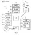
- FIG. 2is a schematic view of a processor circuit for implementing a server shown in FIG. 1 ;
- FIG. 3is a schematic view of a shared buffer implemented in the server processor circuit shown in FIG. 2 ;
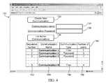
- FIG. 4is a screenshot of a web page displayed on a client computer in the system shown in FIG. 1 ;
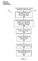
- FIG. 5is a flowchart representing blocks of codes for directing the server processor circuit shown in FIG. 2 to execute a “create new communication process”;
- FIG. 6is a schematic representation of a communication table entry in a communication table maintained by the server processor circuit shown in FIG. 2 ;
- FIG. 7is a schematic representation of a client table entry in a client table maintained by the server processor circuit shown in FIG. 2 ;
- FIG. 8is a flowchart representing blocks of codes for directing the server processor circuit shown in FIG. 2 to execute a “list active multiple-party communications” process;
- FIG. 9is a schematic view of a processor circuit for implementing the client computer shown in FIG. 1 ;
- FIG. 10is a table listing selected mouse and keyboard events implemented in a JavaTM programming language
- FIG. 11is a screenshot of a user interface displayed on the client computers shown in FIG. 1 ;
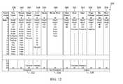
- FIG. 12is a table of message formats used in the system shown in FIG. 1 ;
- FIG. 13A-13Care respective portions of a flowchart representing blocks of codes for directing the client computer processor circuit shown in FIG. 9 to produce messages for transmission to the server processor circuit shown in FIG. 2 ;
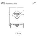
- FIG. 14is a flowchart representing blocks of codes for directing the processor circuit shown in FIG. 9 to transmit the messages to the server processor circuit shown in FIG. 2 ;
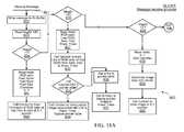
- FIG. 15A-15Bare respective portions of a flowchart representing blocks of codes for directing the processor circuit shown in FIG. 2 to receive messages from the client computer processor circuit shown in FIG. 9 ;
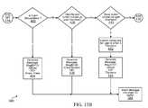
- FIG. 16is a flowchart representing blocks of codes for directing the processor circuit shown in FIG. 2 to process messages for transmission to respective client computers;
- FIG. 17is a flowchart representing blocks of codes for directing the processor circuit shown in FIG. 2 to transmit messages to the client computers;
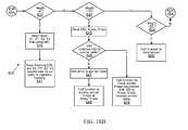
- FIG. 18A-18Bare respective portions of a flowchart representing blocks of codes for directing the client computer processor circuit shown in FIG. 9 to receive messages from the server processor circuit shown in FIG. 2 ;
- FIG. 19is a flowchart representing blocks of codes for directing the processor circuit shown in FIG. 2 to transmit a published multiple-party communication page to the client computers;
- FIG. 20is a flowchart representing blocks of codes for directing the processor circuit shown in FIG. 9 to transmit a game message to the server;
- FIG. 21is a flowchart representing blocks of codes for directing the processor circuit shown in FIG. 9 to display game piece images on respective client computers;
- FIG. 22is a screenshot of an alternate embodiment of a user interface displayed on the client computers shown in FIG. 1 ;
- FIG. 23is a flowchart representing blocks of codes for directing the processor circuit shown in FIG. 9 to move game piece images on respective display areas of the client computers shown in FIG. 1 ;
- FIG. 24is a game piece movement message format used in the system shown in FIG. 1 ;
- FIG. 25is a schematic view of a system for supporting multiple-party communications in accordance with a second embodiment of the invention.
- FIG. 26is a screenshot of a web page transmitted by a server shown in FIG. 25 ;
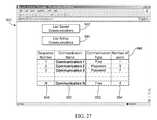
- FIG. 27is a screenshot of another web page transmitted by the server shown in FIG. 25 ;
- FIG. 28is a flowchart representing blocks of codes for directing the processor circuit shown in FIG. 2 to add a designated client computer to an active multiple-party communication;
- FIG. 29is a flowchart representing blocks of codes for directing the processor circuit shown in FIG. 2 to receive messages from the client computers and the designated client computer shown in FIG. 25 ;
- FIG. 30is a screenshot of a web page listing saved multiple-party communications transmitted to the designated client computer by the server shown in FIG. 25 ;
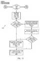
- FIG. 31is a flowchart representing blocks of codes for directing the processor circuit shown in FIG. 2 to respond to a request by a designated client computer to view saved multiple-party communication content;
- FIG. 32is a flowchart representing blocks of codes for directing the processor circuit shown in FIG. 2 to transmit output messages to client computers and the designated client computer shown in FIG. 25 ;
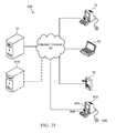
- FIG. 33is a schematic view of a system for supporting multiple-party communications in accordance with a multiple-server embodiment of the invention.
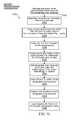
- FIG. 34is a flowchart representing blocks of codes for directing a processor circuit to create a new multiple-party communication in the multiple-server system shown in FIG. 33 ;
- FIG. 35is a schematic view of a system for supporting multiple-party communications in accordance with another embodiment of the invention.
- the system 10includes a server 12 and a plurality of client computers 14 , 16 , and 18 .
- the client computer 14is a conventional desktop computer
- the client computer 16is a laptop computer
- the client computer 18is a handheld computer.
- Each of the client computers 14 , 16 , and 18communicates with the server 12 through a network 20 such as the internet or an intranet, for example.
- Each of the client computers 14 , 16 , and 18has a display 15 , 17 , and 19 respectively for displaying text, characters, and/or graphics on a display area thereof.
- Each of the client computers 14 , 16 , and 18also has a pointing device 22 , 24 , and 26 respectively.
- the pointing device 22is a conventional hand-held pointing device such as a computer mouse
- the pointing device 24is a touchpad
- the pointing device 26is a stylus for providing user input on a touch sensitive display 19 .
- the pointing devices 22 , 24 , and 26generally produce user input signals for moving a cursor on the respective displays 15 , 17 , or 19 , and may additionally provide actuator buttons for producing actuator button signals for performing various other user input functions.
- each of the client computers 14 , 16 , and 18has a character input device shown generally at 28 , 30 , and 32 respectively for receiving user input signals representing characters and for controlling certain operations of the client computer.
- the character input devices 28 and 30are both conventional keyboard input devices.
- the character input device 32may include areas on the touch sensitive display 19 that are mapped to characters, or may alternatively include a handwriting recognition engine for converting the user's handwriting motions of the pointing device 26 on the touch sensitive display 19 into character representations.
- both the pointing devices 22 , 24 , and 26 and the character input devices 28 , 30 and 32are operable to produce user input signals that facilitate user input to the respective client computers 14 , 16 , and 18 .
- Certain user input signalswhether received through the respective pointing device 22 , 24 , or 26 , or through the respective character input device 28 , 30 , or 32 , are formatted into messages by the client computers 14 , 16 , or 18 , and are transmitted through the network 20 to the server 12 .
- the server 12is configured to receive an input message representing user input received at one of the client computers 14 , 16 , or 18 and determine a message type associated with the input message. The server 12 then produces an output message representing the user input provided by the input message. The output message is transmitted to each of the client computer 14 , 16 , and 18 when the input message is associated with a persistent message type. When the input message is associated with a non-persistent message type, the output message is only transmitted to those of the client computers 14 , 16 , and 18 that meet a criterion.
- Messages of the persistent typegenerally produce persistent changes to content on the display area, while messages of the non-persistent type do not result in persistent changes to the display area.
- movements of the pointing device 22are represented by non-persistent messages that are produced by the client computer 14 and transmitted to the server 12 .
- the server 12then produces and transmits an output message back to those of the client computers 14 , 16 , and 18 , to which all previously received messages of the persistent message type have already been transmitted.
- a feature of the system 10is that while user input, such as movements of the pointing device 22 at the client computer 14 , for example, are reflected almost immediately on the display 15 as a corresponding change in position of the cursor, the client computer also transmits a cursor message to the server to elicit a pointer message from the server.
- the cursor messagerepresents a change in a position of the cursor in response to the user input received from the user of the client computer.
- the client computer 14receives the pointer message from the server and causes a corresponding change in a position of a pointer associated with the cursor and displayed on the display 15 in response to the message, which represents the change in position of the cursor.
- each of the client computers 16 , and 18also receive the pointer message representing the change in position of the cursor of the client computer 14 , and cause a corresponding change in a position of a pointer associated with the client computer 14 , which is displayed on the respective display areas 17 and 18 of the client computers in response to the pointer message.
- usersare able to view their own real time cursor and their own and other user's pointers on their respective displays.
- Each useris thus made aware of other user's actions, thus providing a feeling of a real multiple-party presence in the multiple-party communication.
- the system 10facilitates simultaneous user input from all client computers, which is in contrast to some prior art systems that only permit user input from a single designated presenter.
- cursoris used to refer to the client computer cursor on the respective displays 15 , 17 , and 19 .
- pointeris used to refer to a secondary pointer, which is also displayed on the respective displays 15 , 17 , and 19 of the respective client computers 14 , 16 , or 18 .
- system 10further facilitates public access to published content created during a multiple-party communication and the system 10 may further include a public access computer 40 in communication with the server 12 through the network 20 . Publication of multiple-party communication content is described later herein.
- the server processor circuit 50includes a microprocessor 52 , a program memory 54 , a random access memory (RAM) 56 , a persistent memory such as a hard drive 58 , a media reader 59 , and an input output port (I/O) 60 , all of which are in communication with the microprocessor.
- a microprocessor 52a program memory 54 , a random access memory (RAM) 56 , a persistent memory such as a hard drive 58 , a media reader 59 , and an input output port (I/O) 60 , all of which are in communication with the microprocessor.
- RAMrandom access memory
- I/Oinput output port
- the I/O port 60includes a network interface 62 , such as a network interface card having an input/output 64 for connection to the network 20 , and through which communications are conducted with the client computers 14 , 16 , and 18 , as shown in FIG. 1 .
- a network interface 62such as a network interface card having an input/output 64 for connection to the network 20 , and through which communications are conducted with the client computers 14 , 16 , and 18 , as shown in FIG. 1 .
- Program codes for directing the microprocessor 52 to effect server functions of the system 10are stored in the program memory 54 , which may be implemented as a random access memory (RAM), and/or a hard disk drive (HDD), or a combination thereof.
- RAMrandom access memory
- HDDhard disk drive
- the program memory 54includes a block of codes 70 for directing the processor circuit 50 to effect communication manager functions, a block of codes 72 for directing the processor circuit to effect client manager functions, a block of codes 74 for directing the processor circuit to effect page management functions, a block of codes 75 for directing the processor circuit to effect web server functions, and a block of codes 78 for directing the processor circuit to effect game criteria functions.
- the program memory 54may also optionally include a block of codes 76 for directing the processor circuit 50 to effect media relay functions, as will be described later herein.
- the hard drive 58includes a plurality of stores including a client saved content store 100 for storing content displayed during an ongoing communication.
- the hard drive 58also includes a user interface store 101 for storing program codes operable to cause a user interface to be displayed on the client computers 14 , 16 , and 18 , when downloaded by the client computers.
- the hard drive 58further includes a web page store 102 for storing data representing one or more web pages to be displayed on the client computers 14 , 16 , or 18 during the multiple-party communication.
- the data stored in the web page store 102may include Hypertext Markup Language (HTML) data, for example.
- HTMLHypertext Markup Language
- the hard drive 58further includes a communication page store 104 for saving pages of content created during multiple-party communications, an upload data store 106 for storing image data and/or other data uploaded by the client computers 14 , 16 , and 18 to the server 12 , a published communication store 108 for storing published multiple-party communication content, and a game data store 109 for storing data associated with a game being played between client computers during the communication.
- a communication page store 104for saving pages of content created during multiple-party communications
- an upload data store 106for storing image data and/or other data uploaded by the client computers 14 , 16 , and 18 to the server 12
- a published communication store 108for storing published multiple-party communication content
- a game data store 109for storing data associated with a game being played between client computers during the communication.
- the hard drive 58may be substituted by another form of persistent memory, such as a flash memory, for example.
- the media reader 59facilitates loading program codes into the program memory 54 from a computer readable medium 110 such as a CD ROM disk 112 .
- the program codesmay be provided by a computer readable signal 114 , which may be received over a network such as the internet, for example.
- the RAM 56includes a plurality of storage blocks including a communication table storage block 80 for storing a communication table holding information associated with active multiple-party communications being hosted by the server 12 .
- the RAM 56also includes a storage block for each active multiple-party communication in the communication table 80 .
- the processor circuit 50is hosting three active multiple-party communications and accordingly three such storage blocks 82 , 84 , and 86 are shown.
- Each storage block 82 , 84 , and 86includes a shared memory buffer 88 for storing messages received from each of the client computers 14 , 16 and 18 .
- Each storage block 82 , 84 , and 86further includes a client table storage block 90 for storing a client table holding identifications of respective client computers participating in each corresponding multiple-party communication.
- Each storage block 82 , 84 , and 86also includes a plurality of server side receive (Rx) buffers 92 and a plurality of server side transmit (Tx) buffers 94 , including one Rx buffer and one Tx buffer for each client included in the client table 90 .
- Rxserver side receive
- Txserver side transmit
- each storage block and/or buffer in the RAM 56may include a plurality of storage locations implemented in random access memory, for example.
- the shared memory buffer 88is shown in greater detail in FIG. 3 .
- the shared buffer 88includes a plurality of message stores 120 each being of sufficient size to hold one message, which in this embodiment are 30 bytes long.
- Each message store 120(which are labeled as 1 , 2 , . . . n in FIG. 3 ) has an associated memory address.
- a “StartPointer” 122is used to point to one of the message stores 120 to which a first message was written.
- a “CurrentPointer” 124is used to point to one of the message stores 120 to which a last message was written.
- a plurality of client “SentPointer”s 126are used to point to one of the message stores 120 , whose contents were last transmitted to the respective client computer.
- Each of the client computers 14 , 16 , or 18thus has a corresponding “SentPointer” 126 .
- the data pointers 122 and 124are variables stored in the communication table 80 and having respective values that reference (or “point” to) a memory address of one of the message stores 120 .
- the client “SentPointer”s 126are variables stored in an associated client table 90 , having respective values that reference a memory address of one of the message stores 120 .
- the shared buffer 88may be implemented as a circular buffer, in which case after a message has been written to the “n th ” message store 120 , the “CurrentPointer” 124 wraps around and is reset to point to the “1 st ” data store, and newly received messages will overwrite older messages in the shared buffer.
- Each multiple party communication hosted by the server 12has a single associated shared buffer 88 .
- the shared buffer 88is generally operable to store messages received from the client computers 14 , 16 , and 18 that have joined a multiple party communication.
- the shared buffer 88further acts as a memory buffer for storing output messages to be transmitted to the client computers 14 , 16 , and 18 .
- output messagesare produced by copying the input messages into the shared buffer 88 , and accordingly only a single shared buffer 88 is used for each communication.
- output messagesmay have different formats and/or payload data to the input messages and in such embodiments an input shared buffer may be used to hold input messages, and output messages may be produced by reading the payload of the input messages and generating a corresponding output message, which may be stored in an output shared buffer.
- a screenshot of a web page displayed on the client computers 14 , 16 , or 18 when the client computers first connect to the server 12is shown generally at 130 .
- the client computers 14 , 16 , or 18connect to the server 12 by directing a hypertext transfer protocol (HTTP) request for the web page 130 to the network interface 62 of the server processor circuit 50 .
- HTTPhypertext transfer protocol
- the HTTP request from the client computer 14 , 16 , or 18may be generated by a web browser application running on the client computer, for example.
- the web server program codes 75direct the server microprocessor 52 to read data representing the web page 130 from the store 102 on the hard drive 58 , and to transmit the data through the network 20 to the client computer.
- the data representing the web page 130may be communicated in one or more HTTP messages transmitted using a network transport protocol such as transmission control protocol over internet protocol (TCP/IP), for example.
- TCP/IPtransmission control protocol over internet protocol
- the web browser applicationWhen the HTTP data is received by the client computer 14 , 16 , or 18 , the web browser application causes the web page 130 to be displayed in a browser window on a respective display 15 , 17 , or 19 of the client computers.
- the web page 130includes a “create new communication” button 132 and a “CommunicationName” field 134 for the user to enter a communication name.
- the web page 130further includes a “CommunicationPassword” field 136 for optionally assigning a password when creating a new communication, such that access to the communication may be limited to users who are in possession of the password.
- the web page 130further includes a “list active communications” button 138 .
- the client computerWhen a user of one of the client computers 14 , 16 , or 18 (an originating client) enters a communication name in the “CommunicationName” field 134 and clicks on the “create new communication” button 132 , the client computer transmits a signal to the network interface 62 of the server processor circuit 50 to request creation a new communication.
- the transmitted signalmay include an HTTP request message including the communication name and password (if provided).
- FIG. 5a flowchart of blocks of code for directing the processor circuit 50 (shown in FIG. 2 ) to create a new multiple-party communication is shown generally at 150 .
- the blocksgenerally represent codes read from the program memory 54 , for directing the microprocessor 52 to perform various communication manager, client manager, and page manager functions related to creating a new communication.
- the actual code to implement each blockmay be written in any suitable programming language, such as FlashTM, Java, Delphi®, C, and/or C++, for example.
- the communication manager program codes 70direct the microprocessor 52 to provide communication manager functions for creating the new multiple-party communication, and further direct the microprocessor 52 to cause the page manager program codes 74 and the client manager program codes to be launched in the process of creating the new communication.
- the process 150begins at 152 when a signal, such as an HTTP request message, is received from one of the client computers 14 , 16 , or 18 at the network interface 62 , requesting that a new multiple-party communication be created.
- a signalsuch as an HTTP request message
- Block 154then directs the microprocessor 52 to read the communication name provided and the password (if provided) in the HTTP request message received from the client computer. Block 154 further directs the microprocessor 52 to add a new communication entry to the communication table 80 in the RAM 56 .
- the communication table entryis shown in greater detail in FIG. 6 at 180 .
- the communication table entry 180includes a plurality of fields identifying the communication, which are populated when block 154 (shown in FIG. 5 ) directs the microprocessor 52 to add the new communication entry to the communication table 80 stored in the RAM 56 .
- the communication table entry 180includes a communication identifier (“CID”) field 182 , which is populated with a unique communication identifier number assigned to the new multiple-party communication.
- CIDcommunication identifier
- the communication table entry 180also includes a “CommunicationName” field 184 , which is populated with the communication name assigned by the originating client in the “CommunicationName” field 134 on the web page 130 (shown in FIG. 4 ).
- the entry 180also includes a “CommunicationPassword” field 186 , which is optionally assigned by the originating client in the “CommunicationPassword” field 136 on the web page 130 . If no communication password is assigned by the originating client, the “CommunicationPassword” field 186 on the communication table entry 180 is left empty.
- the communication table entry 180further includes a “KeepRunningIdleFlag” field 188 for storing a flag indicating whether the communication should be kept running after the last client has disconnected from the server 12 .
- the communication table entry 180also includes a “StartPointer” field 190 and a “CurrentPointer” field 192 , for storing address values of the “StartPointer” 122 and the “CurrentPointer” 124 respectively, as shown in FIG. 3 .
- the communication table entry 180further includes a list of pages field 194 for storing a listing of the pages created during the communication.
- the entry 180also includes a current page field 196 for storing a value identifying a currently loaded page in the communication.
- the communication table entry 180may also have an associated “HiddenFlag” field 198 for storing a flag value indicating whether the communication should be hidden.
- HiddenFlaga flag value indicating whether the communication should be hidden.
- certain multiple-party communicationsmay be created to allow the public access computer 40 (shown in FIG. 1 ) to access published communication content or to permit lawful intercept authorities to intercept communication content.
- the client computers 14 , 16 and 18are not made aware of the existence of communications for which the hidden flag is set to active.
- Block 156directs the microprocessor 52 to create a new shared buffer 88 and associated the shared buffer with the CID of the multiple-party communication.
- Block 156further directs the microprocessor 52 to initialize the “StartPointer” 122 and the “CurrentPointer” to refer to a first store 120 in the shared buffer 88 and to instantiate a page manager for the multiple-party communication by initiating execution of the page manager program codes 74 .
- Block 158then directs the microprocessor 52 to instantiate a new client manager for the multiple-party communication by launching the client manager program codes in the store 72 .
- the communication managerinstantiates a separate client manager for each communication included in the communication table 80 .
- the communication managercontinues running in parallel with the page manager and the client manager, such that the processor circuit 50 is able continue to provide communication manager functions and/or create other new multiple-party communications.
- the remaining blocks of the process 150directs the microprocessor 52 to perform various client manager functions associated with the newly created multiple-party communication.
- the processcontinues at block 160 , which directs the microprocessor 52 to generate a new client table 90 in the RAM 56 , and to add an identification entry to the client table identifying the originating client computer.
- the client table entryis shown in greater detail in FIG. 7 at 200 .
- the client table entryincludes a plurality of fields identifying the associated client computer, which are populated when block 160 (shown in FIG. 5 ) directs the microprocessor 52 to add the originating client entry to the client table 90 stored in the RAM 56 .
- the client table entry 200includes a client computer identifier field (“UID”) 202 , which is populated with a unique client computer identifier number (“UID”) assigned to the client computer.
- UIDclient computer identifier field
- the client table entry 200further includes a client IP address field 204 , and a client port field 206 , which are populated with values obtained from the header of an internet protocol data packet received from the client computer at the server network interface 62 .
- the client table entry 200further includes a “CatchUpFlag” field 208 , which when set, indicates that the client computer needs to “catch up” with previous data shared during the multiple-party communication.
- the “CatchUpFlag” 208 in the client table entry 200 for the client computeris set to not active, as described later herein.
- the client table entry 200also includes a “SentPointer” 210 , which holds an address of one of the message stores 120 in the shared buffer 88 , corresponding to a message that was last transmitted to the corresponding client computer.
- the client “SentPointer” field 210is initially set to “nil” and is subsequently set equal to the “StartPointer” 122 once a first message is transmitted to the client computer by the server 12 .
- client table entry 200may also have an associated “SilentFlag” 212 for holding a flag value, which when set to active, indicates that the user of the client computer corresponding to the client “UID” is an intercept authority.
- Designated intercept client computersare treated differently by the server than the client computers 14 , 16 and 18 , as described later herein.
- the process 150continues at block 162 , which directs the microprocessor 52 to create a server side Rx buffer 92 and a server side Tx buffer 94 in the RAM 56 for the originating client.
- the server side Rx buffer 92is used to temporarily store messages received from the client computer and the server side Tx buffer 94 is used to temporarily store messages to be transmitted to the client computer.
- Creating the server side Rx buffer 92 and the server side Tx buffer 94may involve opening a network socket for communications between each one of the client computers 14 , 16 , and 18 and the server, for example.
- a network socketis a software function provided by most operating systems that facilitates communications over a computer network.
- Network socket functionsgenerally allocate Rx and Tx buffers which may be used as the Rx and Tx buffers 92 and 94 .
- Block 164then directs the microprocessor 52 to read the user interface codes from the user interface store 101 of the server hard drive 58 and to cause the network interface 62 of the I/O PORT 60 to transmit the user interface codes through the network 20 to client computer that originated the communication.
- FIG. 8a flowchart of blocks of code for directing the processor circuit 50 (shown in FIG. 2 ) to transmit a listing of active multiple-party communications to the client computer is shown generally at 230 .
- the processbegins at 232 when the HTTP message requesting an identification of active multiple-party communications is received at the network interface 62 .
- Block 234directs the microprocessor 52 to read the communication table entries 180 and the corresponding client table entries 200 (shown in FIGS. 6 and 7 respectively) in the communication table 80 and corresponding client table 90 stored in the RAM 56 .
- Block 235then directs the microprocessor 52 to transmit data to client computer identifying active communications being hosted by the server.
- the process 230then ends at 236 .
- the client computerreceives the data from the server 12 and displays a table identifying active multiple-party communications shown generally at 140 .
- the table 140includes a first column 142 listing a sequence number assigned to the multiple-party communication (i.e. 1, 2, 3 . . . for example).
- the table 140also includes a second column 144 listing the communication name from the “CommunicationName” field 184 , and a third column 146 listing a communication type.
- the communication typeis set to “free” when no password has been assigned by the originating user for the multiple-party communication, and to “password” when a password is required to join the multiple-party communication.
- the table 140also includes a fourth column 148 , listing a number of client computer users involved in each respective multiple-party communication.
- the table 140is only displayed after the user activates the “list active communications” button 138 , but in other embodiments the “list active communications” button 138 may be omitted and the table 140 may be displayed when the web page 130 is loaded from the server 12 by the client computer 14 , 16 , or 18 .
- fields in at least one of the columns in the table 140have associated hyperlink properties, which facilitate selection of a particular multiple-party communication by clicking on a hyperlink associated with the multiple-party communication.
- the communication names listed in bold font in column 144may include such hyperlink properties.
- the web browser application program codes 281direct the microprocessor 262 to transmit an HTTP message to the server 12 .
- the HTTP messageincludes an identifier identifying the multiple-party communication, such as the communication name and/or the communication identifier “CID” for the multiple-party communication.
- FIG. 8a flowchart of blocks of code for directing the processor circuit 50 to add the client computer to an active communication is shown generally at 237 .
- the processbegins at 238 when the server processor circuit 50 receives an HTTP request message identifying an active communication that the user of the client computer wishes to join.
- Block 239directs the microprocessor 52 to read the information in the HTTP message received from the client computer and to match the information to a multiple-party communication in the communication table 80 .
- the HTTP messageincludes a communication identifier
- the “CID”is read from the HTTP message and compared with the values in the “CID” field 182 in the communication table entries 180 find the corresponding multiple-party communication.
- the HTTP messageincludes a communication name
- the communication nameis compared with the values in the “CommunicationName” field 184 in the communication table entry 180 to find the corresponding multiple-party communication.
- Block 239also directs the microprocessor 52 to instantiate a client manager for the client computer.
- a separate thread of the client manageris instantiated and associated with each client computer in the communication and each client manager thread is associated with the communication.
- the remaining blocks 240 to 244 in the process 230direct the server processor circuit 50 to perform client manager functions.
- Block 240then directs the microprocessor 52 to add a new client table entry 200 identifying the client computer to the corresponding client table 90 for the selected multiple-party communication. Block 240 also directs the microprocessor 52 to populate the fields in the new client table entry, and to set the “CatchUpFlag” 208 in the client table entry 200 to active and to set the client “SentPointer” field 210 to “nil”.
- the “CatchUpFlag” 208is set to active to cause messages in the multiple-party communication that the client computer user may have missed by joining the multiple-party communication late to be transmitted to the client computer.
- the client “SentPointer” field 210is set equal to the “StartPointer” 122 once the first message is transmitted to the client computer.
- Block 242then directs the microprocessor 52 create server side Rx and Tx buffers 92 and 94 for the client.
- each client computer 14 , 16 , and 18has corresponding server side Rx and Tx buffers, which facilitate transmitting multiple-party communication data that may already have been transmitted to other client computers to client computer users who join a multiple-party communication after the multiple-party communication has started (i.e. all clients other than the originating client for the multiple-party communication).
- Block 244then directs the microprocessor 52 to read the user interface codes from the user interface store 101 and to cause the network interface 62 of the I/O PORT 60 to transmit the user interface codes through the network 20 to the client computer.
- a processor circuit of the client computers 14 , 16 , and/or 18is shown generally at 260 .
- the client processor circuit 260includes a microprocessor 262 , a program memory 264 , a random access memory (RAM) 266 , a media reader 268 , and an input/output port (I/O) 270 , all of which are in communication with the microprocessor 262 .
- RAMrandom access memory
- I/Oinput/output port
- the I/O port 270includes an interface 272 , such as a network interface card having an input/output 274 in communication with the network 20 .
- the interface 272facilitates transmitting messages to the server 12 and receiving messages from the server, as shown in FIG. 1 .
- the interface 272may include a wireless interface for connecting to a wireless network access point 276 , which facilitates connection to the network 20 .
- the I/O port 270further includes an input 278 for receiving user input signals from a character input device (such as the character input device 28 shown in FIG. 1 ), and from a pointing device (such as the pointing device 22 shown in FIG. 1 ).
- a character input devicesuch as the character input device 28 shown in FIG. 1
- a pointing devicesuch as the pointing device 22 shown in FIG. 1
- the I/O port 270further includes an output 279 for producing display signals for causing a client computer display (such as the display 15 shown in FIG. 1 ) to display images, characters, and cursors, for example.
- a client computer displaysuch as the display 15 shown in FIG. 1
- Program codes for directing the microprocessor 262 to effect client functions of the system 10 , shown in FIG. 1are stored in the program memory 264 , which may be implemented as a random access memory (RAM), and/or a hard disk drive (HDD), or a combination thereof.
- the program memory 264includes a block of codes 280 for directing the processor circuit to effect operating system (O/S) functions, and a block of codes 281 for directing the processor circuit to provide web browsing functions.
- the program memory 264also includes a block of codes 282 for directing the processor circuit 260 to effect various user interface functions.
- the block of codes 282includes a first block of codes 284 for directing the processor circuit 260 to effect a message receiver function, a second block of codes 286 for directing the processor circuit to effect a message sender function, a third block of codes 288 for directing the processor circuit to effect interrupt handler functions, and a fourth block of codes 289 for directing the processor circuit 260 to effect display functions.
- the user interface program codes 282are received at the interface 272 in one or more HTTP messages from the server 12 .
- the program codesare then extracted from the HTTP message payload and loaded into the program memory 264 .
- the media reader 268may be used to load user interface program codes from a computer readable medium 300 into the program memory 264 .
- the computer readable medium 300may be a CD ROM disk 302 .
- the program codesmay be provided by a computer readable signal 304 , which may be received over a network such as the internet, for example.
- the RAM 266includes a plurality of storage blocks including a client side receive (Rx) buffer 290 for temporarily storing messages received from the server 12 and a client side transmit (Tx) buffer 292 for temporarily storing messages to be transmitted back to the server 12 .
- the buffers 290 and 292include a plurality of storage locations in the RAM 266 and may be implemented by opening a network socket using operating system functions provided by the operating system 280 .
- the RAM 266also includes a character entry position store 294 for storing coordinates of a character entry position, a pointer table store 295 for storing a table of pointers, and a hyperlink and filename/URL store 296 for storing coordinates and filenames or internet addresses associated with one or more hyperlinks.
- a character entry position store 294for storing coordinates of a character entry position
- a pointer table store 295for storing a table of pointers
- a hyperlink and filename/URL store 296for storing coordinates and filenames or internet addresses associated with one or more hyperlinks.
- the RAM 266further includes a game piece image store 298 for storing information associated with a game that may be played during the multiple-party communication.
- the RAM 266also includes a game piece coordinate 299 store for storing variables representing coordinates of the game piece images.
- the processor circuit 260may optionally include a persistent data store 310 (such as a hard drive) for persistent storage of data.
- the persistent data store 310may be used for persistent storage of program codes, and image files, for example.
- the persistent data store 310may also be used for storage of data related to multiple-party communications. However in the embodiments described herein multiple-party communication data is stored on the server hard drive 58 and the system 10 does not directly make use of persistent data store 310 on the client computer processor circuit 260 .
- client computers 14 , 16 , and/or 18 in a multiple-party communicationproduce messages in response to user input signals and/or combinations of user input signals and function invocations.
- the user input signalsmay include character signals representing character input received from the character input device 28 , cursor movement signals representing a cursor movement produced in response to user input received at a pointing device 22 , and actuator button signals produced in response to user actuation of actuator buttons associated with the pointing device.
- the messages generated by the client computers 14 , 16 and 18are transmitted to the server 12 .
- the operating system program codes 280 in the program memory 264direct the microprocessor 262 to cause the I/O port 270 to monitor signals received at the input 278 from the character input device 28 and the pointing device 22 , and to generate interrupt event signals in response to the user input signals.
- the interrupt event signals produced by the operating systemare read by the user interface interrupt handler 288 .
- interrupt event signalsare written to a message queue and the interrupt handler 288 is registered to receive or listen to certain event signals in the message queue.
- mouse input signalsare produced when a button on the pointing device 22 is actuated and released, the mouse is moved (i.e. no buttons actuated), or the mouse is dragged (i.e. moved while pressing a mouse button).
- the operating systemreceives these signals and produces interrupt event messages including coordinate positions and other information identifying the input, which are written into the message queue.
- keyboard input signalsproduce interrupt event messages which are also written into the message queue.
- the interrupt handler program codes 288further direct the microprocessor 262 to provide functions for reading the message queue and for handling the operating system interrupt event messages. For example, in Java programming language, getX and getY functions are provided for returning the X and Y coordinates of a cursor, which has been moved in response to user input from the pointing device.
- the event “KeyTyped”(KeyEvent e)is invoked following a keyboard interrupt, where the actuated key is represented by a numeric value in a “KeyEvent” object produced by the Java function.
- a table listing selected methods for acting on mouse and keyboard interrupts in the Java programming languageis shown generally at 320 .
- the methods listedinclude a mouseClicked(MouseEvent e) 322 , which is invoked when the mouse button has been actuated, a mouseDragged(MouseEvent e) 324 , which is invoked when a mouse button has been actuated on the mouse and then the mouse has been dragged, a mouseMoved(MouseEvent e) 326 , which is invoked when the mouse cursor has been moved but no buttons have been actuated, and a keyTyped(KeyEvent e) 328 , which is invoked when a key has been typed.
- two or more of the event signalsmay be generated essentially simultaneously in response to the user input.
- the user of the client computer 14 , 16 or 18actuates the mouse button, then drags the mouse while the button is actuated, and then releases the mouse button several event signals are produced.
- the mouse buttonis actuated, none of the events listed in FIG. 10 are produced until the user drags the mouse (a “mousePressed” event is produced, but this event is not used in this embodiment).
- the mouse dragwill produce a plurality of “mouseDragged” event signals while the mouse is being dragged and each individual “mouseDragged” signal or message defines a portion of the movement of the mouse.
- the mouse dragmay thus be defined by a plurality of event signals between a location at which the mouse button was actuated and a location at which the mouse button was released.
- the server 12transmits program codes to the client computer for displaying the user interface 470 (shown in FIG. 11 ) on the client computer display 15 .
- the user interface program codesmay include Java or Flash program codes for directing the microprocessor 262 to provide user interface functions.
- the program codesmay be downloaded from the server 12 and automatically executed after downloading.
- the client computermay launch program codes (not shown) for instantiating a stand-alone user interface program, which causes the user interface 470 to be displayed without being downloaded from the server 12 .
- the user interface 470includes a control panel 471 , a display area 472 for displaying multiple-party communication content, and a status bar 490 .
- the control panel 471includes an “ImageShow” function invocation button 474 for transmitting a message to the server to cause an image 475 to be displayed on the display area 472 , a “ClearScreen” function invocation button 476 for transmitting a message to the server to cause the display area to be cleared, a “Save” function invocation button 477 for transmitting a message to cause the server to save presently displayed content, and an “Open” function invocation button 494 for transmitting a message to cause the server to load and transmit messages representing previously saved content.
- the control panel 471also includes a “PageBack” function invocation button 478 and “PageForward” function invocation button 480 for transmitting a message to the server for causing messages associated with previous displayed pages to be transmitted to the client computers, a “LinkCreate” function invocation button 495 for transmitting a message to the server identifying a link to a web page or previously saved content on the server, and a “Publish” function invocation button 493 for transmitting a message to the server to cause content to be published.
- a “PageBack” function invocation button 478 and “PageForward” function invocation button 480for transmitting a message to the server for causing messages associated with previous displayed pages to be transmitted to the client computers
- a “LinkCreate” function invocation button 495for transmitting a message to the server identifying a link to a web page or previously saved content on the server
- a “Publish” function invocation button 493for transmitting a message to the server to cause content to be published.
- the control panel 471also includes a “Clipboard” function invocation button 488 for uploading clipboard data to the server and for transmitting a message to the server identifying the upload data, and a “Quit” function invocation button 482 for transmitting a message to the server to cause the client computer to be disconnected when the user of the client computer wishes to leave the multiple-party communication.
- the control panel 471further includes a “Game” function invocation button 491 for transmitting as message to the server to cause game piece images to be displayed on the display area 472 , as described later herein.
- the control panel 471further includes line formatting controls 484 for selecting a color and width of a line to be drawn on the display area 472 , and character formatting controls 486 for selecting a font, color, and size of characters to be displayed on the display area.
- user interface 470causes content such as an image 475 , a single client computer cursor 496 , and a client computer pointer 499 for each client computer in the multiple-party communication, to be displayed in response to messages received from the server 12 .
- each client computermay display only its own cursor 496 and other client computer pointers 499 , in which case the client computer user will not be able to view their own pointer on the display area.
- the user interface 470is displayed on the handheld client computer 18 (shown in FIG. 1 ) an actual cursor may not be displayed on the display 19 since the tip of the stylus 26 provides a visual indication of the cursor position.
- the stylus 26acts as the cursor, and although no actual cursor is displayed on the screen, the operating system of such devices receives user input signals in response to movement of the stylus tip in contact with the touch screen display area and produces corresponding interrupt event signals as described above.
- the status bar 490generally display status information associated with the multiple-party communication.
- the status bar 490includes a field 492 for displaying the number of client computers that have joined the multiple-party communication, and may include other information such as the duration of the multiple-party communication, communication name etc.
- the display area 472may also have a linked area 497 , which links to a file or web page when clicked by the user.
- the link 497includes an identifier (not shown) identifying a filename of a file on the server hard drive 58 including image data for the Ethna volcano image 475 .
- the link identifiermay include a uniform resource locator (URL) identifying image data or an image file elsewhere on the network 20 .
- the user interface image display program codes 289direct the microprocessor 262 to cause the client cursor 496 to change from displaying an arrow to display a hand-shaped cursor 498 (in practice, either the arrow cursor 496 or the hand cursor 498 is visible, not both as shown in FIG. 11 for illustrative purposes only).
- the display area 472may include a plurality of linked areas such as the linked area 497 , each linked area having an associated identifier.
- the coordinates of each linked area 497 and the associated identifierare stored in the store 296 in the RAM 266 .
- the linked area 497comprises a rectangular area of the display area 472 and may be defined by a first pair of X and Y coordinates defining a top left hand corner of the linked area and a second pair of X and Y coordinates defining a bottom right hand corner of the linked area.
- the linked area 472may have other geometric shapes having a position and/or shape defined by one or more coordinate pairs.
- a table of messages used in the communication system 10is shown generally at 330 .
- three message typesare provided including:
- Non-persistent messages 334 that do not result in persistent changes to the display areafor example, messages that cause pointers to change position within the display area 472 , but do not leave persistent changes on the display area;
- Control messages 336that cause a server action to be performed for managing server and/or client activity that also do not cause persistent changes to the content in the display area 472 (except for messages that cause page changes or clearing of the screen).
- Each message 330comprises 30 bytes of information, with the 30 th byte being the null character, indicating the end of the message. Any unused bytes in the message are padded with zeroes.
- Each message 330includes a message identifier (MsgID) in bytes 1 and 2 .
- message identifiers in the range 1-9are associated with persistent messages 332
- message identifiers in the range 10-19are associated with non-persistent messages 334
- message identifiers ⁇ 20are associated with control messages 336 .
- the message identifieralso functions as a message type indicator, since the message type may be derived from the message identifier.
- the messages 330may include a separate message type indicator (not shown) indicating a message type associated with each message.
- Each message 330also includes the user identifier (UID) 202 (shown in FIG. 7 ) in bytes 3 and 4 .
- the messages 330may be of different byte size, may have variable byte lengths, and/or may comprise an Extensible Markup Language (XML) message format, for example.
- XMLExtensible Markup Language
- Each message 330represents a particular type of user input and may include addition information, such as coordinate positions, in a message payload.
- the message identifier fieldindicates the specific type of user input included in the message payload
- the persistent messages 332are generated in response to user input that causes persistent lines to be drawn, characters to be displayed, and/or images to be displayed on the user interface 470 .
- the persistent messages 332include a “KeyTyped” message 338 having a message identifier of 1, which represents a user input key (or character).
- the specific key typedis represented by a numeric value held in bytes 11 and 12 .
- the “KeyTyped” message 338also includes X and Y coordinates (Xnew, Ynew) held in bytes 13 - 16 of the message, color display information associated with the character held in the bytes 5 - 7 , a font identifier, style identifier, and a size identifier held in bytes 8 - 10 .
- the persistent messages 332also include a “MouseDrag” message 340 having a message identifier of 2, which represents a line drawn on the display area 472 of the user interface 470 .
- the “MouseDrag” message 340includes starting X and Y coordinates (Xold, Yold) and ending X and Y coordinates (Xnew, Ynew) held in bytes 9 - 16 of the message. Color information associated with the line is held in the bytes 5 - 7 , and a width of the line is held in byte 8 .
- the persistent messages 332also include an “ImageShow” message 342 having a message identifier of 3, which represents an image location (such as the image 475 shown in FIG. 11 ) posted by the user on the client computer display area 472 of the user interface 470 .
- the “ImageShow” message 342also includes X and Y coordinates (Xnew, Ynew) held in bytes 5 - 8 and an image filename held in bytes 9 - 29 .
- the persistent messages 332also include a “LinkCreate” message 344 having a message identifier of 4, which represents a link created by the user on the client computer display area 472 of the user interface 470 (such as the linked area 497 shown in FIG. 11 ).
- the “LinkCreate” message 344also includes X and Y coordinates (X1, Y1) and (X2, Y2) held in bytes 5 - 12 and a filename or internet address held in bytes 13 - 29 .
- the persistent messages 332also include a “Game” message 359 having a message identifier of 5, which represents a request by a user of the client computer to display game piece images on the display area 472 of the user interface 470 .
- the non-persistent messages 334include only a “MouseMove” message 346 having a message identifier of 10, which represents a mouse movement made by the user that causes the cursor to move without drawing a line on the display area 472 .
- the “MouseMove” message 346includes ending X and Y coordinates (Xnew, Ynew) held in bytes 5 - 8 .
- Other embodimentsmay include further non-persistent messages.
- the “MouseMove” message 346 and the “MouseDrag” message 340represent a change in position of a cursor associated with the display area 472 of the client computer, and when transmitted to the server 12 these messages may be referred to as cursor messages.
- the control messagesgenerally cause functions to be performed by the server 12 , but generally do not produce new content on the display area 472 .
- the control messages 336include a “ClearScreen” message 348 having a message identifier of 20, which represents a command to clear a page displayed on the display area 472 .
- the control messages 336also include a “Save” message 350 having a message identifier of 21, which represents a request by a client computer user to save content currently displayed on the display area 472 to the client saved content store 100 in the server hard drive 58 (shown in FIG. 2 ).
- the “Save” message 350includes a filename, which is held in bytes 5 - 29 of the message.
- the control messages 336also include an “Open” message 352 having a message identifier of 22, which represents a request by a user to load content saved in the client saved content store 100 in the server hard drive 58 .
- the “Open” message 352includes a filename, which is held in bytes 5 - 29 of the message.
- the control messages 336also include a “PageChange” message 354 having a message identifier of 23, which represents a request by a user to change the current displayed page to a page stored in the communication page store 104 .
- the communication page store 104may store several pages of content and accordingly the “PageChange” message 354 includes a “PageFlag” value held in byte 5 of the message for instructing the server 12 to display a previous page (when the “PageFlag” value is “0”), or to display the next page (when the “PageFlag” is “1”).
- the control messages 336also include a “Disconnect” message 356 having a message identifier of 24, which represents a request of the user to disconnect from the multiple-party communication, while the multiple-party communication continues.
- the control messages 336also include a “ShutDown” message 358 having a message identifier of 25, which represents a request by the user to discontinue the multiple-party communication.
- the message sender process codes stored in the store 286 of the program memorydirect the microprocessor 262 to produce the persistent messages 332 , the non-persistent messages 334 , and the control messages 336 , in response to user input signals, function button invocations, and combinations thereof.
- FIG. 13A to FIG. 13Ca flowchart of blocks of code for directing the client computer processor circuit 260 (shown in FIG. 9 ) to generate the messages is shown generally at 360 .
- the processbegins at 362 when an interrupt event signal produced by the operating system is received by the interrupt handler 288 .
- Block 364directs the microprocessor 262 to determine whether the interrupt event signal corresponds to a “keyTyped” event 328 (shown in FIG. 10 ), in which case the process continues at block 366 , which directs the microprocessor to generate the “KeyTyped” message 338 with a message identifier value of 1, a “UID” 202 corresponding to the user identifier of the client computer from the client table entry 200 (shown in FIG. 7 ), and color and font values corresponding to a color and font currently selected by the user in the character formatting controls 486 on the user interface.
- Block 366also directs the microprocessor to read the X and Y coordinates of the character entry position from the character entry position store 294 in the RAM 266 and to place values of these coordinates in the “KeyTyped” message 338 .
- each messageincludes information identifying only a single typed character. In other embodiments the message may represent more than one character.
- the processthen continues at block 367 , which directs the microprocessor 262 to compute a new character entry position for the next character that will be typed by the user of the client computer.
- subsequent charactersare assigned X and Y coordinates read from the character entry position store 294 , and after each successive character is typed, the X coordinate is incremented (or decremented for in some alphabets) such that the next character typed will be displayed in an appropriate spaced apart relation to the previous character typed. Successive typed characters thus appear in a horizontal line and have the same Y coordinate.
- the Y coordinateis incremented (assuming that the display area 472 has an origin at the top left hand corner) such that the next character typed will be displayed on a new line below the previous character or characters in an appropriate spaced apart relation.
- the X coordinateis also decremented (or incremented in some alphabets) to cause the character entry position to align horizontally with the first character in the previous line.
- the X coordinate of the first character in a lineis saved in the character entry position store 294 and thus when an “Enter” or new line control character is typed the character entry position X coordinate is set to the X coordinate of the first character in the previous line and the Y coordinate is computed as described above.
- Block 367also directs the microprocessor 262 to update the character entry position stored in the store 294 in accordance with the new computed character entry position.
- the processthen continues at block 384 , which directs the microprocessor 262 to write the message 338 into the client side Tx buffer 292 .
- Block 368directs the microprocessor 262 to determine whether the interrupt event signal corresponds to a “mouseDragged” event 324 , in which case the process continues at block 370 .
- Block 370directs the microprocessor 262 to determine whether the “LinkCreate” function invocation button 495 (shown in FIG. 11 ) was clicked before the mouse was dragged. If the “LinkCreate” button 495 was clicked, then the process continues at block 371 .
- Block 371directs the microprocessor 262 to generate the “MouseMove” message 346 with a message identifier value of 10, a “UID” corresponding to the user identifier for the client computer, and X and Y coordinates corresponding to the new cursor location on the display area 472 .
- the processthen continues at block 384 , which directs the microprocessor 262 to write the message 346 into the client side Tx buffer 292 .
- Block 382directs the microprocessor to generate the “MouseDrag” message 340 with a message identifier value of 2, a “UID” corresponding to the user identifier for the client computer, and color and width values corresponding to a color and width currently selected in the line formatting controls 484 .
- Block 382also directs the microprocessor to query the operating system to retrieve starting X and Y coordinates and ending X and Y coordinates corresponding to the cursor motion to place these values in the appropriate bytes of the payload of the message 340 .
- the processthen continues at block 384 , which directs the microprocessor 262 to write the message 340 into the client side Tx buffer 292 .
- Block 372directs the microprocessor 262 to determine whether the event corresponds to a “mouseClicked” event 322 , in which case the process continues at block 374 .
- Block 374directs the microprocessor 262 to determine whether the “ImageShow” function invocation button 474 (shown in FIG. 11 ) was clicked before the mouse click was produced. If the “ImageShow” function invocation button 474 was clicked, then the process continues at block 376 , which directs the microprocessor to launch a dialog window (not shown) for the user to pick an image to be displayed on the display area 472 .
- the imagemay be represented by data stored in the persistent data store 310 or the RAM 266 of the processor circuit 260 , or the image data may be stored in a location elsewhere on the network 20 .
- block 377which directs the microprocessor 262 to upload the image data to the server processor circuit 50 .
- the uploading of the image datamay be performed in accordance with a conventional file upload protocol such as file transfer protocol (FTP).
- block 377may direct the microprocessor 262 to initiate a HTTP POST request for uploading the image data to the server using HTTP protocol, for example.
- the upload dataalso includes an associated upload data identifier, such as a filename.
- block 377may further direct the microprocessor 262 to generate a unique upload data identifier, for example by combining the client computer UID with a time and date generated by the operating system.
- Block 375directs the microprocessor 262 to determine whether the “Clipboard” function invocation button 488 was clicked before the mouse click was produced. If the “Clipboard” button 488 was clicked, then the process continues at block 377 as described above, except that in this case the microprocessor 262 is directed to upload the clipboard data to the server.
- Block 378then directs the microprocessor 262 to generate the “ImageShow” message 342 with a message identifier value of 3, a “UID” corresponding to the user identifier for the client computer, and a upload data identifier corresponding to the upload data identifier associated with the upload data, that was transmitted to the server 12 at block 377 .
- Block 378also directs the microprocessor 262 to retrieve the X and Y coordinates of the display location where the mouse actuator button was actuated in block 372 , which defines the position of the top left hand corner of the image (such as the image 475 shown in FIG. 11 ).
- Block 378further directs the microprocessor 262 to place these values in the appropriate bytes of the “ImageShow” message 342 .
- the processthen continues at block 384 , which directs the microprocessor 262 to write the message 342 into the client side Tx buffer 292 .
- the information in the “ImageShow” messagemay be uploaded at block 377 , in which case block 378 may be omitted.
- the upload datamay be screenshot image data of a desktop area of the client computer.
- screenshotsmay be conveniently produced when using the Microsoft Windows operating system by pressing a “Print Screen” key on the keyboard to copy the entire desktop to clipboard memory, or by pressing “Alt” and “Print Screen” keys to copy the content of an active window to the clipboard memory.
- Screenshot datais generally in some image data format (for example a bitmap) and may be uploaded directly to the server from the clipboard or converted into a different image format by an image conversion function (not shown).
- the data in the clipboard memorymay be formatted data copied from a program window (for example Microsoft® Office Word or Excel).
- Formatted datamay include formats, such as Excel spreadsheet formats for example, and such data is generally not suitable for display as an image. Accordingly, when a user of one of the client computers 14 , 16 , or 18 wishes to upload formatted data, the data may require conversion into a format suitable for display as an image.
- Such data conversionsare generally performed by conversion functions that are configured to convert particular types of formatted data into image data.
- the conversionis performed by the server 12 after the data has been uploaded from the client computer to the server.
- the data conversionmay be performed by the client computer prior to uploading at block 377 .
- the formatted datamay be uploaded to the server 12 and stored on the server without conversion, and the data conversion may be performed on each of the client computers after the formatted data is downloaded for display on the respective display areas 472 .
- the conversiongenerally involves determining a formatted data type by reading clipboard parameters associated with the data in the clipboard memory. An appropriate conversion function is then selected from a plurality of conversion functions available and the formatted data is converted into an image format suitable for display in the user interface 470 .
- conversion functionsmay be included in the user interface 282 program codes, and launched when performing an upload of formatted data to the server 12 or when downloading formatted data from the server.
- the clipboard function invocationfacilitates sharing content produced by other software applications during the multiple-party communication. All client computers will display the resulting image and will be able to draw lines and type characters over the image.
- Block 380directs the microprocessor 262 to determine whether the “mouseClicked” event (at block 372 ) was immediately preceded by a “mouseDragged” event 324 , in which case the process continues at block 381 .
- Block 381directs the microprocessor 262 to determine whether the “LinkCreate” function invocation button 495 (shown in FIG. 11 ) was clicked before the mouse was dragged. If at block 381 the “LinkCreate” button 495 was clicked, then the process continues at block 385 .
- Block 385directs the microprocessor 262 to launch a dialog box for a user to enter a link identifier to be associated with a linked area 497 .
- the link identifiermay include a filename identifying a location and name of a client saved content in the client saved content store 100 on the server hard drive 58 (shown in FIG. 2 ).
- the link identifiermay be a Uniform Resource Locator (URL) of another web site (for example www.google.com).
- Block 386directs the microprocessor 262 to generate the “LinkCreate” message 344 with a message identifier value of 4, a “UID” corresponding to the user identifier for the client computer, and the link identifier provided by the client computer user.
- Block 386also directs the microprocessor 262 to query the operating system to retrieve starting X and Y coordinates corresponding to starting coordinates of the mouse drag, and ending X and Y coordinates corresponding to the ending coordinates of the mouse drag.
- Block 386further directs the microprocessor 262 to write the retrieved coordinate values to appropriate bytes of the message 346 .
- the starting X and Y coordinates and ending X and Y coordinatesdefine the linked area 497 on the display area 472 shown in FIG. 11 .
- the processthen continues at block 384 , which directs the microprocessor 262 to write the message 344 into the client side Tx buffer 292 .
- block 380If at block 380 the event does not correspond to a “mouseDragged” event 324 then the process continues at block 388 .
- block 388directs the microprocessor 262 to determine whether the mouse click was within one of the linked areas 497 defined by information stored in the store 296 of the RAM 266 (shown in FIG. 9 ).
- the processcontinues at block 389 , which directs the microprocessor 262 to generate the “Open” message 352 with a message identifier value of 22, a “UID” corresponding to the user identifier for the client computer, and a link identifier corresponding to a filename or internet address associated with the linked area 497 .
- the processthen continues at block 384 , which directs the microprocessor 262 to write the message 352 into the client side Tx buffer 292 .
- the character entry position stored in the store 294is initially set to a default position for character entry, such as location (10, 10) on the display area 472 , for example (i.e. 10 pixels down and 10 pixels to the right from the top left hand corner of the display area 472 ).
- a default position for character entrysuch as location (10, 10) on the display area 472 , for example (i.e. 10 pixels down and 10 pixels to the right from the top left hand corner of the display area 472 ).
- the character entry positionis implemented as a “sticky” position, which causes user input characters to be displayed on the display area 472 at the last character entry position saved in the store 294 , or the default position if the user has not set a previous character entry position by clicking on the display area 472 without clicking first on the “ImageShow”, “Clipboard”, or “LinkCreate” function invocation buttons 474 , 488 , or 495 respectively.
- block 402directs the microprocessor 262 to determine whether the interrupt event signal corresponds to a “mouseMoved” event 326 (shown in FIG. 10 ), in which case the process continues at block 404 .
- Block 404directs the microprocessor 262 to generate the “MouseMove” message 346 with a message identifier value of 10, a “UID” corresponding to the user identifier for the client computer, and X and Y coordinates corresponding to the new cursor location on the display area 472 .
- the processthen continues at block 384 , which directs the microprocessor 262 to write the message 346 into the client side Tx buffer 292 .
- the client computer user's pointing device movementsmay be represented in real time by a cursor displayed by the operating system on the client computer display area 472 or by a stylus tip on a touch screen display area.
- the “MouseMove” message 346facilitates transmitting the client computer user's pointing device movements to other client computers, which facilitates display of pointers corresponding to each of a plurality of client computers on the respective display areas 472 of the other client computers who have joined the multiple-party communication.
- the client computer that generates the “MouseMove” message 346also receives a copy of the message back from the server, which facilitates display of a local pointer in addition to any cursor that may be displayed by the operating system.
- display of a cursor and a local pointerpermits the client computer user to view the effect of their pointer movements, since while the cursor responds to pointing device movements in near real-time, the pointer only moves once the message representing the movement is received back from the server.
- the pointerwhen the pointing device is moved, the pointer generally trails the cursor, providing a useful view of a network latency associated with a round trip from one of the client computers 14 , 16 , or 18 to the server 12 and back again to the client computer.
- the cursor and the pointerWhen the pointing device is not moving, the cursor and the pointer will generally be displayed in the same location on the display area 472 .
- the stylus tipacts as a cursor and the pointer trails the stylus tip, thus providing a similar view of network latency for the user.
- Block 406directs the microprocessor 262 to determine whether the user has clicked the “ClearScreen” button 476 . If the “ClearScreen” button 476 has been clicked, then block 408 directs the microprocessor 262 to generate the “ClearScreen” message 348 with a message identifier value of 20 and a “UID” corresponding to the user identifier for the client computer. The process then continues at block 384 , which directs the microprocessor 262 to write the message 348 into the client side Tx buffer 292 .
- Block 410directs the microprocessor 262 to determine whether the “Save” button 477 has been clicked, in which case the process continues at block 412 .
- Block 412directs the microprocessor 262 to launch a dialog box for receiving user input of a filename.
- Block 414then directs the microprocessor 262 to generate the “Save” message 350 with a message identifier value of 21, a “UID” corresponding to the user identifier for the client computer, and a filename corresponding to the filename input by the user.
- the processthen continues at block 384 , which directs the microprocessor 262 to write the message 350 into the client side Tx buffer 292 .
- block 416directs the microprocessor 262 to determine whether the user has clicked the “Open” button 494 . If the “Open” button 494 has been clicked, then block 418 directs the microprocessor 262 to launch a dialog box for receiving user input of a filename. Block 420 then directs the microprocessor to generate the “Open” message 352 with a message identifier value of 22 and a “UID” corresponding to the user identifier for the client computer. The process then continues at block 384 , which directs the microprocessor 262 to write the message 352 into the client side Tx buffer 292 .
- Block 422directs the microprocessor 262 to determine whether either of the “PageBack” or “PageForward” buttons 478 or 480 has been clicked, in which case the process continues at block 424 .
- Block 424directs the microprocessor 262 generate the “PageChange” message 354 with a message identifier value of 23, a “UID” corresponding to the user identifier for the client computer, and a “PageFlag” value of “0” where the “PageBack” button was clicked or “1” where the “PageForward” button was clicked.
- the processthen continues at block 384 , which directs the microprocessor 262 to write the message 354 into the client side Tx buffer 292 .
- Block 426directs the microprocessor 262 to determine whether the “Quit” button 482 has been clicked, in which case the process continues at block 428 .
- Block 428directs the microprocessor 262 to open a dialog window (for example a checkbox dialog form—not shown) to present the user with an option of disconnecting the client while keeping the multiple-party communication running or shutting down the multiple-party communication.
- a dialog windowfor example a checkbox dialog form—not shown
- the processthen continues at block 430 , which directs the microprocessor 262 to determine whether the user has chosen to disconnect, in which case block 432 directs the microprocessor 262 to generate the “Disconnect” message 356 with a message identifier value of 24 and a “UID” corresponding to the user identifier for the client computer.
- block 384which directs the microprocessor 262 to write the message 356 into the client side Tx buffer 292 .
- the processcontinues at block 434 , which directs the microprocessor 262 to generate the “ShutDown” message 358 with a message identifier value of 25 and a “UID” corresponding to the user identifier for the client computer.
- the request to shut down the communicationis only accepted by the server 12 if the user is the last client computer in the communication.
- the processthen continues at block 384 , which directs the microprocessor 262 to write the message 358 into the client side Tx buffer 292 .
- the client computerwhen the client computer receives user input signals and/or function invocation signals representing a function invocation at the client computer, the client computer produces a message having a message type associated with one of a plurality of pre-defined combinations of the user input signals and function invocation signals and transmits the message to the server 12 .
- the process 360 shown in FIG. 13A-13Cthus represents a pre-association of certain combinations and/or sequences of user input signals and function invocations that produce messages having one of the persistent, non-persistent and control message type. Other user input signals and combinations such as mouse click events outside the user interface, are ignored by the message sender process.
- FIG. 14a flowchart of blocks of code for directing the processor circuit 262 (shown in FIG. 9 ) to transmit the messages stored in the client side Tx buffer 292 is shown generally at 440 .
- messagesmay be transmitted in accordance with any message transmission protocol, such as TCP/IP, user datagram protocol (UDP), or XML, for example.
- TCP/IPTransmission Control Protocol/Internet Protocol
- UDPuser datagram protocol
- XMLXML
- the processbegins at block 442 , which directs the microprocessor 262 to determine whether there are any messages in the client side Tx buffer 292 , in which case block 444 directs the microprocessor 262 to read the next message in the Tx buffer on a first-in-first-out (FIFO) basis and to write the message to the interface 272 .
- the interface 272then produces a data signal representing the message at the input/output 274 , which is transmitted to the server 12 through the network 20 .
- the process 440then returns to block 442 , repeating blocks 442 and 444 until all messages in the client side Tx buffer are transmitted.
- the microprocessor 262is directed back to block 442 , which again determines whether any messages have been written into the client side Tx buffer 292 .
- FIGS. 15A and 15BA flowchart of blocks of code for directing the processor circuit 50 (shown in FIG. 2 ) to receive input messages from each of the client computers 14 , 16 and 18 is shown in FIGS. 15A and 15B generally at 500 .
- client manager threadsare executed for each of the client computers 14 , 16 , and 18 to separately receive input messages in the respective server side Rx buffers for the client computers.
- the processbegins at blocks 502 , 504 and 506 , which direct the microprocessor 52 wait for input messages to be received from any of the client computers 14 , 16 , and 18 at any of the server side Rx buffers 92 in the RAM 56 .
- Block 508then directs the microprocessor 52 append a timestamp to the input message (after byte 30 , shown in FIG. 12 ).
- Block 510then directs the microprocessor 52 to produce an output message by inserting the message in the shared buffer 88 (shown in FIG. 3 ) at a next message store 120 after the message store referenced by the “CurrentPointer” 124 .
- Block 510further directs the microprocessor 52 to update the “CurrentPointer” 124 to reference the message store 120 in the shared buffer to which the output message was written, such that the “CurrentPointer” always points to the last message written to the shared buffer 88 .
- the output messagesare produced by copying the input message into the shared buffer.
- output messages having different message identifiers or differing format to the input messagesmay be produced, as described above.
- the input messageseach represent one user input combination (for example a mouse drag or a character typed) and the output messages produced represent the same user input combination.
- the input messagesmay represent several user input combinations and the output message produced by the server may represent the same user input combinations, or may combine user input combinations in a plurality of input messages into a singe output message.
- Block 512then directs the microprocessor 52 to determine the message type associated with the input message, by reading the message identifier.
- the message typesince the output message is a copy of the corresponding input message the message type may be determined by reading the message identifier in either the input message or the output message.
- the processthen continues at block 514 , which directs the microprocessor 52 to determine whether the message is a control type message (i.e. the message identifier ⁇ 20). If the message is not a control type message then it is either a persistent or non-persistent message type the microprocessor 52 is directed back to 502 , 504 , and 506 to wait for the next message to be received in the respective Rx buffers.
- a control type messagei.e. the message identifier ⁇ 20
- input messages of the persistent message type and the non-persistent message typedo not require further processing by the server 12 .
- cursor messages received at the server representing “MouseDrag” and “MouseMove” user input signalsare copied into the shared buffer 88 as pointer messages, which do not require execution of server functions other than transmitting to the client computers.
- the messageis a control message which directs the server to execute a server function.
- the processthen continues at block 516 , which directs the microprocessor 52 to determine whether the message identifier is 20, which corresponds to the “ClearScreen” message (Shown in FIG. 12 at 348 ). If the message identifier is 20, then the process continues at block 518 , which directs the microprocessor 52 to set the “StartPointer” 122 (shown in FIG. 3 ) to refer to a memory store 120 in the shared buffer 88 after the location at which the “ClearScreen” message was inserted.
- client computers joining the multiple-party communicationonly receive messages subsequent to the last “ClearScreen” message, thus avoiding displaying a plurality of persistent messages in quick succession followed by a “ClearScreen” message, which may clear the screen before the user has had time to view the content on the display area 472 .
- the “StartPointer” 122 , the “CurrentPointer” 124 and the “Client SentPointers” 126may be set to nil, as they were when communication just started. This will have the effect of overwriting all messages in the shared buffer 88 . Accordingly, in this alternative embodiment, the shared buffer 88 may be saved to persistent memory prior to overwriting any previous messages.
- the processcontinues at block 520 , which directs the microprocessor 52 to determine whether the message identifier is 21, which corresponds to the “Save” message (Shown in FIG. 12 at 350 ). If the message identifier is 21, then the process continues at block 522 , which directs the microprocessor 52 to copy all persistent messages (i.e. the messages having a message identifier ⁇ 10) from the shared buffer 88 to the client saved content store 100 on the server hard drive 58 . In this embodiment, only the persistent type messages are saved to the hard drive in response to the client save message. Client saved content may be saved in a server page storage format, described later herein.
- the processcontinues at block 524 , which directs the microprocessor 52 to determine whether the message identifier is 22, which corresponds to the “Open” message (Shown in FIG. 12 at 352 ). If the message identifier is 22, then the process continues at block 526 , which directs the microprocessor 52 to save the shared buffer 88 in the communication page store 104 of the server hard drive 58 and then to clear the shared buffer by setting both the “StartPointer” 122 and the “CurrentPointer” 124 to nil, which has the effect of causing further messages to overwrite previously saved messages in the shared buffer 88 .
- a pagethus generally includes a plurality of messages that define content on the display area (and which may be retransmitted to re-create the content, if desired).
- the communication page store 104includes a dedicated sub-directory created in a directory structure that saves communication pages by date and time. For example, for a communication having a communication name “MyTravel” the communication pages are saved in a sub-directory “ ⁇ 2007-03-23 ⁇ 15-39-10 ⁇ My Travel ⁇ ”. Within the “MyTravel” directory each page has a corresponding sub-directory (for example “ ⁇ 2007-03-23 ⁇ 15-39-10 ⁇ My Travel ⁇ Page1 ⁇ and/or “ ⁇ 2007-03-23 ⁇ 15-39-10 ⁇ My Travel ⁇ Page2 ⁇ ”).
- Page 2If during the communication Page 2 is again displayed, and content added to the page, then the original page is saved to a file in the “Page 2” subdirectory under a filename “Page2-1”, or “Page2-2”.
- memory allocated to the shared buffer 88may be limited, and when the sheared buffer is overwritten, content is first written to a Page file such as “Page2-3”, for example.
- the directory “ ⁇ 2007-03-23 ⁇ 15-39-10 ⁇ My Travel ⁇ Page2 ⁇will include files Page2-1, Page2-2, and Page3-3.
- Each of the filesincludes one or more messages separated by the zero terminator (#0 or byte 30 of the messages shown in FIG. 12 ).
- Each filefurther includes a header including identifier information such as, when the file was created, the number of clients in the communication, the communication name & password, and other parameters associated with the communication.
- the filemay include the following header in a text format:
- the “#0” zero terminatoris followed by a plurality of messages, each being separated from the next message by the zero terminator.
- block 526further directs the microprocessor 52 to generate a clear screen message (message 348 shown in FIG. 8 ) and to load the message into the shared buffer 88 for transmission to the client computers 14 , 16 and 18 .
- the clear screen message 348causes content associated with messages previously transmitted to the respective client computers 14 , 16 , and 18 to be cleared, when the message is received at the respective client computers.
- Block 526also directs the microprocessor 52 to read the number of pages from the “List of Pages” field 194 (shown in FIG. 6 ) and to set the “Current Page” field 196 to a next number in sequence, to update the “List of Pages” field 194 , thus creating new page on the server as described above.
- Block 526further directs the microprocessor 52 to read the filename in the message and to load messages saved under the filename from the client saved content store 100 into the shared buffer 88 , to set the “StartPointer” 122 to reference the first loaded message. As the shared buffer 88 is loaded with subsequent messages read from the page file, the “CurrentPointer” 124 is incremented to reference the last loaded message store 120 . Block 526 also directs the microprocessor 52 to set the “CatchUpFlag” to active and the SentPointer to nil, so that all client computers catch up with the newly opened page.
- block 528directs the microprocessor 52 to determine whether the message identifier is 23, in which case the control message is a “PageChange” Message (shown in FIG. 12 at 354 ). If the message is a “PageChange” message, then the process continues at block 530 , which directs the microprocessor 52 to read the “PageFlag” in the message. If the “PageFlag” is “0” then the process continues at block 532 , which directs the microprocessor 52 to determine whether the current displayed page (identified by the current page field 196 shown in FIG.
- Block 534directs the microprocessor 52 to save the shared buffer 88 associated with the current displayed page in the communication page store 104 on the hard drive 58 , clear the contents of the shared buffer 88 by setting both the “StartPointer” 122 and the “CurrentPointer” 124 to nil, and then to decrement the “Current Page” field 196 to point to the new page to be displayed.
- Block 534further directs the microprocessor 52 to generate a clear screen message (i.e. the message 348 shown in FIG. 8 ) and to load the message into the shared buffer 88 for transmission to the client computers 14 , 16 and 18 .
- the clear screen message 348is operable to clear content associated with messages previously transmitted to the respective client computers 14 , 16 , and 18 when received at the respective client computers.
- Block 536directs the microprocessor 52 to read the saved page corresponding to the “Current Page” field 196 from the communication page store 104 on the server hard drive 58 into the shared buffer 88 .
- Block 536also directs the microprocessor 52 to set the “CatchUpFlag” to active and to set the “SentPointer” to “nil”. This has the effect of transmitting all messages loaded in the shared buffer to each of the client computers 14 , 16 and 18 , since each user must “catch up” with the changed page.
- Block 530directs the microprocessor 52 to determine whether the current displayed page is the last page in the “List of Pages” field 194 , in which case the process continues at block 540 .
- Block 540directs the microprocessor 52 to save the shared buffer 88 associated with the current page in the communication page store 104 on the hard drive 58 and clear the contents of the shared buffer 88 by setting both the “StartPointer” 122 and the “CurrentPointer” 124 to nil.
- Block 540also directs the microprocessor 52 to increment the “Current Page” field 196 to point to the new current page to be displayed, to set the “CatchUpFlag” to active, and to set the “SentPointer” to “nil”.
- Block 540further directs the microprocessor 52 to generate a clear screen message (i.e. the message 348 shown in FIG. 8 ) and to load the message into the shared buffer 88 for transmission to the client computers 14 , 16 and 18 .
- the clear screen message 348is operable to clear content associated with messages previously transmitted to the respective client computers 14 , 16 , and 18 when received at the respective client computers.
- the codes in block 540essentially cause the server to generate a new blank page.
- Block 542directs the microprocessor 52 to save the shared buffer 88 associated with the current displayed page in the communication page store 104 on the hard drive 58 , to clear the contents of the shared buffer 88 by setting both the “StartPointer” 122 and the “CurrentPointer” 124 to nil, and then to increment the “Current Page” field 196 to point to the new page to be displayed.
- Block 542further directs the microprocessor 52 to generate a clear screen message (i.e. the message 348 shown in FIG. 8 ) and to load the message into the shared buffer 88 for transmission to the client computers 14 , 16 and 18 .
- the clear screen message 348is operable to clear content associated with messages previously transmitted to the respective client computers 14 , 16 , and 18 when received at the respective client computers.
- the processthen continues at block 536 as described above.
- the processcontinues at block 544 , which directs the microprocessor 52 to determine whether the message identifier is 24, in which case the message corresponds to the “Disconnect” message (shown in FIG. 12 at 356 ). If the message identifier is 24, then the process continues at block 546 , which directs the microprocessor 52 to set the “KeepRunningIdleFlag” 188 in the communication table 80 to active.
- the processthen continues at block 548 , which directs the microprocessor 52 to remove the client corresponding to the “UID” in the message from the client table 90 in the RAM 56 and to delete the Rx and Tx buffers for the client computer.
- the processthen continues at block 550 , which directs the microprocessor 52 to determine whether the client table is empty (i.e. there are no more clients in the multiple-party communication). If the client table is empty then the process continues at block 552 , which directs the microprocessor 52 to determine whether the “KeepRunningIdleFlag” flag 188 in the communication table 80 is active (which it will be in this case due to block 546 having been executed), in which case the process continues at block 558 and the multiple-party communication is suspended. However the communication table entry 180 (shown in FIG. 6 ) remains in the communication table 80 in the RAM 56 , and client computer users may still join the multiple-party communication at a later time.
- the multiple-party communicationshould continue for other client computers still in the multiple-party communication, in which case the microprocessor 52 is directed back to blocks 502 , 504 , and 506 in FIG. 15A .
- the processcontinues at block 554 , which directs the microprocessor 52 to determine whether the message identifier is 25, in which case the message is a “ShutDown” message (shown in FIG. 12 at 358 ). The process then continues at block 556 , which directs the microprocessor 52 to set the “KeepRunningIdleFlag” flag to not active.
- Block 560directs the microprocessor 52 to save the shared buffer in the communication page store 104 on the server hard drive 58 , to delete the shared buffer 88 from RAM 56 , and to delete the communication table entry 180 from the communication table 80 . This has the effect of shutting down the multiple-party communication. However a record of all multiple-party communication messages (persistent and non-persistent) remains saved in the communication page store 104 on the server hard drive 58 .
- upload datais initiated by the client computer to the server 12 .
- upload datais received by the server 12 and stored in the upload data store 106 on the server hard drive 58 .
- the upload datamay be stored in an upload data store (not shown) in the RAM 56 .
- the user interface embodiment shown in FIG. 11may not be capable of displaying certain types of data that may be uploaded from client computer clipboard memory to the server, such as formatted data from other application programs, for example.
- the server 12receives upload data (for example as an HTTP POST request from a client computer)
- the serverreads the data to determine whether the upload data requires conversion. If the upload data is already in a supported image format then no conversion is required and the data is stored in the upload data store 106 and associated with the data identifier. If the upload data is not of a supported image format, the server invokes a conversion function to convert the upload data into a supported image format.
- the servermay be configured with a plurality of common conversion functions covering many commonly used formatted data types (for example Microsoft Word and Excel applications). Conversion function program codes for producing image data from many formatted data types are generally available for license by software vendors and third party vendors.
- FIG. 16a flowchart of blocks of code for directing the processor circuit 50 (shown in FIG. 2 ) to process messages in the shared buffer 88 for transmission to the client computers 14 , 16 and 18 is shown generally at 580 .
- the process 580is executed by the microprocessor 52 for each of the client computers 14 , 16 , and 18 and messages are loaded into each of the respective Tx buffers 94 in the server RAM 56 .
- the processbegins at block 584 , which directs the microprocessor 52 to determine whether the “SentPointer” 126 (shown in FIG. 3 ) for the client computer is equal to the “CurrentPointer” 124 . If the “SentPointer” 126 is equal to the “CurrentPointer” 124 , then the process continues at block 586 , which directs the microprocessor 52 to determine whether the “CatchUpFlag” 208 is active for the client computer. If the “CatchUpFlag” is active, then block 588 directs the microprocessor 52 to set the “CatchUpFlag” 208 to not active, since the client computer has “caught up” with the multiple-party communication. The microprocessor 52 is then directed back to block 584 , and the process 580 is repeated.
- the processcontinues at block 590 , which directs the microprocessor 52 to determine whether the message identifier for the message in the next shared buffer store after the store indicated by the “SentPointer” is less than 10, indicating that the message is a persistent message. If the message identifier is less then 10, then the process continues at block 592 , which directs the microprocessor 52 to load the message referenced by the “SentPointer” 210 (shown in FIG. 7 ) into the Tx buffer 94 corresponding to the client.
- all client computers that have joined the multiple-party communicationreceive output messages that are associated with the persistent message type.
- the processthen continues at block 596 , which directs the microprocessor 52 to update the “SentPointer” for the client to indicate that the message has been transmitted to the client computer.
- the microprocessor 52is then directed back to block 584 , and the process 580 is repeated.
- the messageis a non-persistent or control message and the process continues at block 594 , which directs the microprocessor 52 to determine whether the “CatchUpFlag” for the client computer is set active. If the “CatchUpFlag” is not active then the process continues at block 592 as described above the non-persistent and/or control message is transmitted to the client computer.
- the client computerwhen the “CatchUpFlag” is set active for a client computer, the client computer does not meet the criterion for transmission of the message and the non-persistent and control message are not transmitted to the corresponding client computer. If at block 594 the “CatchUpFlag” is active, then the process continues at block 596 , as described above.
- FIG. 17a flowchart of blocks of code for directing the processor circuit 50 (shown in FIG. 2 ) to transmit messages from the server side Tx buffers 94 (for each of the client computers 14 , 16 and 18 ) is shown generally at 597 .
- the processbegins at block 598 , which directs the microprocessor 52 to determine whether there are any messages in the Tx buffer. If there are messages in the Tx buffer to be sent, then the process continues at block 600 , which directs the microprocessor 52 to write the messages to the network interface 62 of the I/O port 60 . The process then continues at block 598 , thus repeating blocks 598 and 600 .
- only clients that meet the criterion of being “caught up” with the multiple-party communicationare transmitted the non-persistent messages in order to avoid sending generally confusing non-persistent mouse movements to clients who have joined the multiple-party communication late.
- the clientOnce the client has caught up with the multiple-party communication the client then receives all non-persistent messages representing their own pointer movements as well as pointer movements of other clients in the multiple-party communication.
- control messageswill also be transmitted to the client computers, since control messages are also stored in the shared buffer.
- control messages transmitted to the clientsdo not result in any changes to the client display area 472 and are generally ignored by the client computers.
- Messages loaded into the Tx buffers 94 of the respective client computersare transmitted to the client computers through the network 20 in the order in which they are loaded into the buffer (i.e. on a first-in-first-out FIFO basis).
- the message receiver program codes stored in the store 284 of the program memorydirect the microprocessor 262 to receive and process messages transmitted to the client computer 14 , 16 , and 18 from the server 12 .
- FIG. 18Aa flowchart of blocks of code for directing the processor circuit 260 (shown in FIG. 9 ) to receive messages from the server 12 is shown generally at 620 .
- the process 620starts at block 621 when a message is received at the interface 272 of the I/O port 270 .
- Block 622then directs the microprocessor 262 to write the message into the client side Rx buffer 290 (shown on FIG. 9 ).
- Block 623then directs the microprocessor 262 to read the message identifier (MID) and client computer identifier (UID) included in the message.
- MIDmessage identifier
- UIDclient computer identifier
- the processcontinues at block 624 , which directs the microprocessor 262 to determine whether the message identifier is 1. If the message identifier is 1, then the message corresponds to the “KeyTyped” message 338 (shown in FIG. 12 ), and the process continues at block 626 , which directs the microprocessor 262 to read the bytes in the message corresponding to color, font identifier, font style identifier, font size, the character to be displayed, and the X and Y coordinates of the position at which to display the character. The process then continues at block 628 , which directs the microprocessor 262 to call a function in the image display program codes 289 for drawing the character on the display area 472 .
- Block 624the process continues at block 630 , which directs the microprocessor 262 to determine whether the message identifier is 2. If the message identifier is 2, then the message corresponds to the “MouseDrag” message 340 , which is a pointer message. Block 631 then directs the microprocessor 262 to read the bytes in the message corresponding to color, line width, starting coordinates Xold and Yold, and ending coordinates Xnew and Ynew.
- Block 632then directs the microprocessor 262 to call a function in the image display program codes 289 for drawing a line of specified color and width between the starting X and Y coordinates and the ending X and Y coordinates on the display area 472 .
- the processthen continues at block 633 which directs the microprocessor 262 to determine whether the UID read in block 631 matches one of the UID's in the pointer table 295 stored in the RAM 266 .
- the pointer table 295includes an entry (not shown) for each client computer in the multiple-party communication and each entry includes the UID and the current X and Y coordinate position of the pointer associated with the UID. If none of the pointer table entries has a UID that matches the UID read at block 631 , then the process continues at block 635 , which directs the microprocessor 262 to add a new entry (i.e. UID, Xnew, Ynew) to the pointer table 295 .
- the processthen continues at block 637 , which directs the microprocessor 262 to call a function in the image display program codes 289 to cause a pointer associated with the UID to be displayed at the Xnew and Ynew coordinate position on the display area 472 .
- Block 634directs the microprocessor 262 to call a function in the image display program codes 289 for moving the image of the pointer from its current position (read from the pointer table) to the Xnew and Ynew coordinate position on the display area 472 .
- Block 648also directs the microprocessor 262 to update the coordinate position in the pointer table 295 for the pointer associated with the UID read at block 631 to the new coordinates Xnew and Ynew.
- Block 636directs the microprocessor 262 to determine whether the message identifier is 3. If the message identifier is 3 then the message corresponds to the “ImageShow” message format 342 . Block 638 then directs the microprocessor 262 to read the bytes in the message corresponding to the data identifier of the image, and the X and Y coordinates at which an upper left hand corner of the image is to be positioned on the display area 472 . Block 640 then directs the microprocessor 262 to download the data associated with the data identifier from the server 12 . Downloading may be performed in accordance with any conventional file download protocol such as file transfer protocol (FTP), for example. Alternatively block 640 may direct the microprocessor 262 to initiate an HTTP GET request to cause the image file to be downloaded to the client computer from the server 12 .
- FTPfile transfer protocol
- the processthen continues at block 642 , which directs the microprocessor 262 to call a function in the image display program codes 289 for displaying the image at the X and Y coordinates on the display area 472 .
- block 637directs the microprocessor 262 to determine whether the message identifier is 4. If the message identifier is 4, then the message corresponds to the “LinkCreate” message format 344 , in which case block 639 then directs the microprocessor 262 to read the bytes in the message corresponding to the “UID”, the X1, Y1, X2, and Y2 coordinates representing coordinate positions of corners of the linked area 497 (shown in FIG. 11 ), and the filename or internet address in the message 344 .
- the processthen continues at block 641 , which directs the microprocessor 262 to store the filename or internet address and coordinates X1, X2, Y1, and Y2 in the filename/URL store 296 in the RAM 266 (shown in FIG. 9 ).
- a mouse click occurring within one of the linked areas defined by hyperlink information stored in the store 296causes the associated filename or internet address to be opened in the display area 472 .
- Block 644directs the microprocessor 262 to determine whether the message identifier is 10. If the message identifier is 10, then the message corresponds to the “MouseMove” message format 346 , which is a pointer message. Block 645 then directs the microprocessor 262 to read the bytes in the message corresponding to the “UID”, and the Xnew and Ynew coordinates representing the ending position of the mouse pointer.
- the processthen continues at block 646 which directs the microprocessor 262 to determine whether the UID read in block 645 matches one of the UID's in the pointer table 295 stored in the RAM 266 . If none of the pointer table entries has a UID that matches the UID read at block 645 , then the process continues at block 646 , which directs the microprocessor 262 to add a new entry (i.e. UID, Xnew, Ynew) to the pointer table 295 .
- UIDUID
- XnewXnew
- the processthen continues at block 649 , which directs the microprocessor 262 to call a function in the image display program codes 289 to cause a pointer associated with the UID to be displayed at the Xnew and Ynew coordinate position on the display area 472 .
- Block 646the process continues at block 648 , which directs the microprocessor 262 to call a function in the image display program codes 289 for moving the image of the pointer from its current position (read from the pointer table 295 ) to the Xnew and Ynew coordinate position on the display area 472 .
- Block 648also directs the microprocessor 262 to update the coordinate position in the pointer table 295 for the pointer associated with the UID read at block 645 to the new coordinates Xnew and Ynew.
- the client computerwhen the client computer receives its own “MouseMove” messages back from the server as pointer messages, the client computer displays a pointer corresponding to the pointer message.
- the client computermay display a cursor representing a current (real time) position of the client computer pointing device and further displays the pointer corresponding to its own “MouseMove” messages, which represent the position of the client computer's pointing device as seen by the server 12 and the other client computers in the multiple-party communication.
- Each client computeris thus provided with feedback by receiving their own pointer message, which causes display of their own pointer on their display.
- the client computer 14may cause their cursor 496 to move to point to specific content displayed on the display area 472 and the users of other client computers 16 and 18 will see corresponding movements of the pointer 499 corresponding to the client computer 14 on their respective displays.
- the user of client computer 14will also be able to view their own pointer in relation to their cursor, which may be useful for guiding the user's actions.
- Block 644the process continues at block 654 , which directs the microprocessor 262 to determine whether the message identifier is 20. If the message identifier is 20, then the message corresponds to the “ClearScreen” message format 348 . Block 656 then directs the microprocessor 262 to call a function in the image display program codes 289 for clearing the display area 472 .
- a user of one of the client computers 14 , 16 , or 18may wish to publish content created during a multiple-party communication to facilitate viewing by other computers in communication with the network 20 .
- a client computer usermay wish to record a page that may be later viewed by another user, who may not have joined the multiple-party communication.
- a client computer usermay wish to record content created in a single client communication and then make the page(s) publicly available for viewing in similar fashion to that provided by web sites on the internet.
- a dialogue windowis displayed (not shown), which prompts the user to enter a filename under which the multiple-party communication will be published (for example “travel.web”).
- the dialogue windowmay additionally prompt the user to enter a description for the published page, such as “My European Vacation”, for example.
- the server processor circuit 50shown in FIG. 2 ) causes all persistent messages representing content in a currently displayed page to be written to the published communication store 108 on the server hard drive 58 .
- the “Publish” function invocation button 493generally launches a similar process to the process launched by the “Save” button 477 (i.e. blocks 410 , 412 , and 414 in FIG. 13B ) except that the persistent messages are saved to the published communication store 108 rather than the client saved content store 100 .
- published content in the published communication store 108are generally made available to anyone who wishes to view the pages, while saved content in the client saved content store 100 is generally only available to client computer users who have joined a multiple-party communication that caused the respective pages to be saved.
- non-persistent messagesmay also be saved to the published pages store to facilitate replaying non-persistent mouse movements to the public access computer.
- Any user of a computersuch as the public access computer 40 shown in FIG. 1 , which has a connection to the network 20 , may view a published multiple-party communication.
- the userconnects to the server 12 and transmits a request for a web page listing published multiple-party communications (not shown) saved in the published communication store 108 .
- the web pagegenerally includes a published pages table that includes information similar to the information listed in table 140 on the web page 130 (shown in FIG. 4 ), except that each entry corresponds to a published page rather than an active multiple-party communication.
- the usermay type URL of the published page (for example www.freemeeting.com/travel.web) into an address field of an internet browser application such as Microsoft Internet Explorer.
- a flowchart representing blocks of codes for directing the microprocessor 52 to create a communication for viewing published pagesis shown generally at 680 .
- the process 680is similar to the process 150 shown in FIG. 5 , in that a communication is created for the public access computer user, thus providing various communication functions generally as described above.
- the communication for viewing published contentmay only have single computer user as a participant.
- certain functions generally available in active multiple-party communicationsare not necessary for viewing a published multiple-party communication and such functions may be disabled, as described below.
- the serverresponds to a request from a public access computer including an identifier identifying published content associated with a previous communication.
- the serverthen reads saved messages associated with the identifier from persistent memory storage on the server and produces respective output messages representing the content in the saved messages.
- the output messagesare then transmitted to the computer.
- the process 680begins at 682 when a public access computer user clicks on a hyperlink to a published multiple-party communication in the web page listing available published communication content, which causes a HTTP request message including identifier identifying the selected published multiple-party communication to be transmitted to the server 12 .
- the identifierincludes the filename under which the multiple-party communication was published and/or the description provided by the client computer user when the content was published.
- Block 684then directs the microprocessor 52 to read the HTTP message to extract the identifier.
- Block 684also directs the microprocessor 52 to create a communication for viewing the content by adding a new communication entry to the communication table 80 (shown in FIG. 2 ).
- communications created for viewing of published pagesare created with the “HiddenFlag” 198 set to active, such that the communication is not listed when the web page 130 is displayed to client computer users who request information on active multiple-party communications as per previously described embodiments.
- the “CommunicationName’ field 184 in the communication table entry 180may be populated with the filename or the description read from the HTTP message, or may be set to a default value.
- a new unique communication identifier (CID)is also generated for the communication and stored in the CID field 182 in the communication table 80 in the RAM 56 .
- Block 686then directs the microprocessor 52 to create a new shared buffer 88 (shown in FIG. 2 ) for the communication, and to initialize the “StartPointer” 122 and the “CurrentPointer” 124 to both refer to a first store in the shared buffer 88 .
- Block 686also directs the microprocessor 52 to instantiate a page manager for the communication by launching the page manager program codes in the store 74 of the program memory 54 .
- Block 688then directs the microprocessor 52 to instantiate a new client manager for the communication by launching the client manager program codes in the store 72 of the program memory 54 .
- Block 690then directs the microprocessor 52 to generate a new client table 90 in the RAM 56 , to add an entry to the client table for the public access computer.
- block 690also directs the microprocessor 52 to set the “CatchUpFlag” to active, such that only persistent type messages are transmitted to the public access computer 40 .
- persistent, non-persistent, and control type messagesmay be transmitted to the public access computer 40 .
- Block 692then directs the microprocessor 52 to create server side Rx and Tx buffers 92 and 94 for the originating client.
- Block 694then directs the microprocessor 52 to cause the network interface 62 of the I/O PORT 60 to transmit published pages user interface codes through the network 20 to the public access computer.
- the public access computermay launch program codes (not shown) for instantiating a stand-alone published pages user interface application.
- Block 696then directs the microprocessor 52 to read messages from the published page identified by the filename read from the HTTP message in block 684 and to load the messages into the shared buffer.
- the “StartPointer” 122is set to reference the message store 120 in the shared buffer 88 to which the first message was loaded. As the message stores 120 of the shared buffer 88 are loaded with subsequent messages read from the published page file, the “CurrentPointer” 124 is incremented to reference the last loaded message store.
- the published pages user interfacemay be generally similar to the user interface 470 , except that user interface function invocation buttons 474 , 476 , 477 , 495 , 488 , 493 , and 491 , the line formatting controls 484 , and the character formatting controls 486 , may be disabled or not displayed in the user interface. Accordingly, only the “Open” function invocation button 494 , the “PageBack” function invocation button 478 , the “PageForward” function invocation button 480 , and the “Quit” function invocation button 482 are still active when viewing a published content.
- the aforementioned function invocation buttonsgenerally operate as described above in connection with FIG. 13A-FIG . 13 C.
- the persistent messages associated with the published page in the published communication store 108are then processed generally in accordance with the process 580 shown in FIG. 16 .
- the output messagesare then transmitted to the public access computer in accordance with the process 597 shown in FIG. 17 .
- the public access client computer 40may cause user input signals to be produced but only certain user input signal and function invocation combinations will be processed in accordance with the process 360 shown in FIG. 13A-FIG . 13 C. For example, in this embodiment, only blocks 416 , 418 and 420 (“Open” function invocation), block 388 , and 389 (link area clicked), block 422 and 424 (“PageBack” and “PageForward” function invocations), and/or block 426 - 434 (“Quit” function invocation buttons) are processed by the public access computer.
- Block 389directs the microprocessor 262 to generate the “Open” message 352 with a message identifier value of 22, and a “UID” corresponding to the user identifier for the public access computer, and a filename or internet address associated with the linked area 497 .
- the filenamemay be a filename of other published messages in the published communication store 108 .
- the processthen continues at block 384 , which directs the microprocessor 262 to write the message 352 into the client side Tx buffer 292 .
- the linked areas 497thus facilitate providing published content with functioning hyperlink areas to other saved messages and/or other content available elsewhere on the network 20 .
- Block 418launches a dialog (not shown) for user to enter the filename of other published content in the published communication store 108 , for example “inLondon.web”.
- Block 420then directs the microprocessor 262 to generate the “Open” message 352 with a message identifier value of 22, and a “UID” corresponding to the user identifier for the public access computer, and a filename entered by user in dialog box at block 418 .
- the processthen continues at block 384 , which directs the microprocessor 262 to write the message 352 into the client side Tx buffer 292 .
- the blocks 422 and 424are launched causing a page change message to be transmitted to the server 12 .
- the useris permitted to page back and forward through these pages in accordance with the blocks 528 - 542 in the process 500 shown in FIG. 15B .
- block 426 in the process 360is launched. However blocks 428 , 430 and 432 are not launched for public access computers.
- the server 12determines whether the communication is to keep running or be shut down.
- the communication created for the public access computer 40 to view a published pagemay be shut down in accordance with blocks 548 - 560 shown in FIG. 15B after the published page has been transmitted to the computer user.
- the published page viewwill remain displayed on the public computer display, but the communication that facilitated transmitting the page will be closed. Accordingly, each time the user of the public access computer 40 requests another page by clicking on a linked area 497 on the published page, for example, a new communication is created to serve the requested page to the user.
- the communicationmay be kept running, transmitting different content files from published communication store 108 in response to the public access computer user requests, until the user disconnects from the communication by clicking on the quit button, as described earlier herein.
- This communicationwill only have a single participant since the Hidden flag 198 is set to active so that other client computers cannot join the communication.
- the published multiple-party communication contentmay be transmitted to public computer user one message at a time with a time interval between messages corresponding to the timestamp appended to the messages at block 508 in FIG. 15A as described later herein with reference to FIG. 32 .
- Thispermits the public access computer user to view the published multiple-party communication content at a rate that matches the rate at which the content was created in the original multiple-party communication.
- a new communicationmay be created for each public access computer user that wishes to view the published page at the original content creation rate, thus facilitating delayed transmission of messages from a shared buffer associated with the communication.
- the servermay share the communication for the same published content between multiple public access computers, in which case the same communication (having the same CID) may be used to serve the published pages to second and subsequent public access computers. When the last user disconnects from the communication, the communication may then be shut down.
- shared public communicationswhen any user clicks on linked areas 497 , “Open”, “PageBack” or “PageForward” buttons, all users of public client computers will be transmitted messages associated with the new page.
- This type of multiple-party communicationis suitable when the published content does not have Link areas, and server also repeatedly transmits the same content over and over again in a repeating looped presentation.
- a public access computer userwho is not capable of producing web pages by conventional methods (for example using Microsoft FrontPage® or using hypertext markup language) may record content in a communication and publish the content, thus making the pages available to the public in general. Publishing such pages does not require any specialized knowledge, while providing a simple interface (i.e. the user interface 470 ) for producing content including images, lines and character annotations and links to other content.
- the server 12is generally configured to act as a content recorder, facilitating subsequent playback of the recorded content to any computer user who is connected to the network 20 .
- the published pagesmay be browsed by a user in the user interface in a similar manner to browsing web pages in a web browser.
- system for supporting multiple-party communicationsmay further facilitate playing of a game between parties who have joined a multiple-party communication.
- Display of game piece imagesis initiated when a user of one client computer user clicks on the “Game” function invocation button 491 on the user interface 470 .
- Image data representing the game piece images and initial position coordinates for displaying the game piece imagesare stored in the store 298 of the client computer RAM 266 .
- FIG. 20a flowchart of blocks of code for directing the processor circuit 260 (shown in FIG. 9 ) to generate the game message 359 is shown generally at 710 .
- the blocks in the process 710generally represent a modification to the process 360 shown in FIG. 13 .
- Block 714directs the microprocessor 262 to generate the “Game” message 359 with a message identifier value of 5 and a “UID” corresponding to the user identifier of the client computer that invoked the game function.
- the processthen continues at block 384 , which directs the microprocessor 262 to write the message 350 into the client side Tx buffer 292 .
- the message 359is then transmitted to the server 12 in accordance with the process 440 shown in FIG. 14 .
- the server 12receives the “Game” message 359 from the client computer in accordance with blocks 508 - 512 of the process 500 shown in FIG. 15 as described above. Once inserted into the shared buffer at block 510 the “Game” message 359 is then processed for transmission in accordance with the process 580 shown in FIG. 16 , and transmitted to all client computers in accordance with the process 597 shown in FIG. 17 , as described above.
- FIG. 21a flowchart representing blocks of code for directing each client computer processor circuit 262 to display the game piece images is shown generally at 720 .
- the blocks in the process 720generally represent a modification to the process 620 shown in FIG. 18B .
- the process 720begins at block 722 , which directs the microprocessor 262 to determine whether the message received at block 621 in FIG. 18A has a message identifier of 5. If the message identifier is 5, then the process continues at block 724 , which directs the microprocessor 262 to read game piece image data and respective position coordinates from the store 298 and to call a function in the image display program codes 289 (shown in FIG. 9 ) for displaying each game piece image on the display area 472 at positions corresponding to the respective position coordinates for each game piece image.
- a screenshot of the user interface 470(shown in FIG. 11 ) is shown having a display area 740 that includes game piece images 742 displayed thereon.
- the game piece images 742include a game board image 744 , a plurality of white game piece images 746 and a plurality of black game piece images 748 .
- Each of the game piece images 742are displayed at initial position coordinates read from the store 298 of the client computer RAM 266 .
- Each game piece image 746 and 748includes an image boundary 747 (shown in broken outline), which defines the image extent of the respective game piece.
- the processthen continues at block 726 , which directs the microprocessor 262 to write the respective position coordinates to the game piece coordinates store 299 in the client computer RAM 266 , such that subsequent movements of the game pieces by the client computer users may be tracked in position coordinate values stored in the game piece coordinates store 299 .
- the game board image 744is displayed at a fixed coordinate position on the display area 740 , while the game piece images 746 and 748 may be moved in response to user input signals received at the respective client computers.
- FIG. 23a flowchart representing blocks of code for directing the microprocessor 262 to move the game piece images on the display area 740 is shown generally at 770 .
- the process 770 shown in FIG. 23is a modification of the process 620 shown in FIG. 18A .
- game piece images 746 and 748are moved in response to cursor messages representing “MouseDragged” user input signal combinations.
- the game piece imagesmay be moved in response to cursor movement signals in combination with character input signals produced at the keyboard (for example, when the user presses a “Ctrl” key while simultaneously moving the pointing device.
- the message identifieris 2
- the messagecorresponds to the “MouseDrag” cursor message 340 .
- the processcontinues at block 632 , which directs the microprocessor 262 to read the bytes in the cursor message corresponding to color, line width, starting coordinates Xold and Yold, and ending coordinates Xnew and Ynew.
- Block 772then directs the microprocessor 262 to determine whether the position coordinates Xnew and Ynew represent a position on the display area 740 that is inside the boundary 747 of one of the game piece images represented by coordinates stored in the game piece coordinates store 299 in the RAM 266 , in which case the process continues at block 774 .
- Block 774then directs the microprocessor 262 to call a function in the image display program codes 289 to delete the game piece image at and redraw the game piece image at a new location Xg, Yg on the display area.
- Block 775then directs the microprocessor 262 to write the new game piece position coordinates into the game piece coordinate store 299 in the RAM 266 .
- Block 776then directs the microprocessor 262 to determine whether the position coordinates Xold and Yold define a position on the display area 740 that is inside one of the game piece coordinate areas stored in the game piece coordinates store in the RAM 266 , in which case the process continues at block 648 .
- Block 648then directs the microprocessor 262 to call a function in the image display program codes 289 for moving the image of the pointer from its current position on the display area 740 to the Xnew and Ynew coordinate position on the display area 740 .
- Block 634directs the microprocessor 262 to call a function in the image display program codes 289 for drawing a line of specified color and width on the user display area 740 between the starting coordinates Xold and Yold, and ending coordinates Xnew and Ynew.
- the pointerwhen the user input signals cause the client computer's pointer 499 to be dragged across the boundary 747 of one of the game piece images 746 or 748 the pointer “pushes” the game piece image to a new location, while simultaneously drawing a line on the display area.
- the user input signalscause client computer's pointer 499 to be dragged inside the boundary 747 , the game piece image is moved without drawing a line on the display area 740 .
- the linemay be discontinued when the pointer crosses the boundary 747 or the line may be drawn behind the game piece image and game board 744 .
- the game piece imagesare moved in response to pointer messages received at the client computers, and not in response to the corresponding client computer cursor 496 , thus facilitating some server arbitration of game piece movements in accordance with the timestamp of the messages representing game piece movements received from the client computers.
- the server 12only receives cursor messages and produces pointer messages which are transmitted to the client computers.
- the client computersreceive the pointer messages
- the pointer messagesare interpreted by the client computer processor circuit 260 to cause corresponding game piece image movements on each of the respective display areas 740 , such that each user receives a common view of the game piece images 742 .
- desired game piece movementsmay be represented by a game piece movement request message shown generally at 780 .
- the piece movement request messages 780are transmitted by the client computers 14 , 16 , and 18 to the server 12 in response to user input signals representing movements that cross the boundary 747 or are within the boundary.
- the piece movement request message 780is a persistent message having a message identifier of 6.
- the piece movement request message 780represents a “MouseDrag” combination of user input signals between starting X and Y coordinates (Xold, Yold) and ending X and Y coordinates (Xnew, Ynew) held in bytes 5 - 12 of the message.
- the piece movement request message 780further includes an “Owner UID” field held in bytes 13 - 14 of the message.
- the “Owner UID” fieldholds a UID corresponding to the UID of the client computer that owns the game piece that it is desired to move.
- the white game pieces 746may be assigned to the first client computer user and the white game piece coordinates stored in the store 299 of the client computer RAM 266 include an associated “Owner UID” corresponding to the UID of the first client computer.
- the black game pieces 748may be assigned to the second client computer and the black game piece coordinates stored in the store 299 of the client computer RAM 266 include an associated “Owner UID” corresponding to the UID of the second client computer.
- the piece movement request message 780further includes an identifier field held in bytes 15 - 16 of the message.
- the identifieridentifies a particular game piece image that the client computer user wishes to move. For example, in a game of checkers, the white checkers may be assigned number indices of 1-12 and the black game pieces may be assigned indices of 13-24.
- a piece movement request message 780is produced and transmitted to the server 12 .
- the server 12receives the message 780 generally in accordance with the process shown in FIG. 15A .
- the serverwhen the server receives a “Game” message 359 requesting display of game piece images for playing a game, the server launches the game criteria program codes 78 , which direct the microprocessor 52 to wait for piece movement request messages 780 to be received from the client computers playing the game.
- the game criteria program codes 78additionally directs the microprocessor 52 to store game piece position coordinates in the game data store 109 for keeping track of the game piece image position coordinates.
- the game data storeis loaded with initial position coordinates of the game piece images.
- the game criteria program codesdirect the microprocessor 52 to determine whether the piece movement request message meets a criterion associated with rules of the game being played. For example, if the server receives a piece movement request message 780 having an Owner UID held in bytes 13 - 14 that does not correspond to the UID held in bytes 3 - 4 of the message, then the message represents an attempt by a client computer user to move a game piece that has been assigned to another client computer user, and the server ignores the piece movement request message.
- the server 12may also compute a desired move magnitude represented by the X and Y coordinates held in the bytes 5 - 8 of the message 780 and determine whether the piece movement request meets a movement criterion associated with the game being played. Similarly, the server 12 may enforce other game rules by determining whether the piece movement request message represents a move that meets a criterion for the game piece identified by the identifier held in bytes 15 - 16 of the message 780 .
- the game criteria program codes 78directs the microprocessor 52 to produce a game piece movement message, which in this embodiment has the same format as the message 780 .
- the piece movement messageis then loaded into the shared buffer 88 and transmitted to the client computers in accordance with the processes 580 and 597 shown in FIG. 16 and FIG. 17 respectively.
- desired game piece actionsmay be represented by a game piece action message shown generally at 782 .
- the piece action messages 782are transmitted by the client computers 14 , 16 , and 18 to the server 12 in response to user input signals representing desired game piece actions.
- actuation of a mouse actuator buttone.g. a right mouse button
- the optionsmay include flipping the card to show the face or the back of the card, making the card private such that other users are prevented from viewing flipping the card etc.
- the optionsmay include a selection of a piece when promoting a pawn that has reached the eighth rank of the chessboard, for example.
- the piece action request message 782is a persistent message having a message identifier of 7.
- the piece action request message 782represents a requested action and includes an “Owner UID” field held in bytes 5 - 6 of the message.
- the “Owner UID” fieldholds a UID corresponding to the UID of the client computer that owns the game piece that it is desired to act upon.
- the game piece action request message 782further includes the identifier field held in bytes 7 - 8 of the message, which identifies a particular game piece image that the client computer user wishes to act upon.
- the piece action request message 782also includes an action type field held in byte 9 of the message.
- the action type fieldholds an action indicator index, for example, “flip”, “private” or “public” for a game of cards.
- the game criteria program codes 78 on the server processor circuit 50direct the microprocessor 52 to determine whether the piece action request message 782 meets a criterion associated with rules of the game being played. For example if a game piece action request to flip a card includes a UID and Owner UID that are different, and the game piece has previously been designated as “private” by the owner, then the action request will not be processed by the server and not transmitted to client computers.
- the game criteria program codes 78directs the microprocessor 52 to produce a piece action message representing the action.
- the piece action messagehas the same format as the message 782 and is transmitted to the client computers as described above.
- the system 800includes the server 12 and a plurality of client computers 14 , 16 , and 18 , such as those shown in FIG. 1 .
- the system 800further includes a designated client computer 802 , which has a display 804 for displaying content.
- the designated client computer 802communicates with the server 12 through the network 20 .
- the designated client computer 802also has a pointing device 806 and a character input device 808 for producing user input signals.
- the designated client computer 802is used by a lawful intercept authority to access and/or intercept multiple-party communications. In general, when permitting lawful intercept or access to private communications, it is important to only authorize such access to a lawful intercept authority.
- Authorizing the designated client computer 802may involve authenticating a user of the designated client computer.
- the system 800may optionally include an authentication server 810 for authenticating a user of the designated client computer 802 .
- the authentication server 810generally stores usernames, passwords, and/or other user information and provides an authentication indicator to the server 12 when credentials supplied by a user have been validated by the authentication server.
- the authentication server 810may implement a Remote Authentication Dial-In User Service (RADIUS) protocol, for example.
- the server 12may provide such authentication functions.
- the authentication server 810may further provide authentication services for authenticating users of the client computers 14 , 16 , and/or 18 .
- the designated client computer 802may be located in a secure controlled environment and the client computer may be authorized for access by users who have access to the secure controlled environment.
- the designated client computer 802may be implemented using the processor circuit 260 shown in FIG. 9 and the user interface 470 shown in FIG. 11 .
- the designated client computer 802generally operates in essentially the same way as the other client computers 14 , 16 and 18 .
- the designated client computers in a multiple-party communicationare identified by the “SilentFlag” 212 in the client table entry 200 shown in FIG. 7 .
- a screenshot of a web page displayed on the designated client computer 802 when the designated client computer first connects to the server 12is shown generally at 820 .
- the communication manager program codes 70direct the microprocessor 52 of the server processor circuit 50 shown in FIG. 2 to read data representing a web page from the web page store 102 of the server processor circuit hard drive 58 and to transmit the data through the network 20 to the designated client computer.
- the request from the designated client computer 802is generated by an internet browser application running on the designated client computer 802 and when web page data is received the web page 820 is displayed in an internet browser window on the display 804 .
- the web page 820includes a “username” field 822 , a “password” field 824 , and an “OK” button 826 .
- a user of the designated client computer 802enters their username in the “username” field 822 , enters their password in the “password” field 824 , and clicks on the “OK” button 826 , a message including the username and password credentials is transmitted to the server 12 (or to the authentication server 810 , if provided). If the user credentials are authenticated by the server 12 (or the authentication server 810 ), then the designated client computer is permitted access to communication manager functions provided for users of the designated client computer 802 .
- the communication manager program codes 70then direct the microprocessor 52 to read data representing a saved communication pages web page from the web page store 102 and to transmit the data to the designated client computer 802 .
- the web page 840includes a “list saved communications” button 842 , and a “list active communications” button 844 .
- the table 846includes a first column 848 listing a multiple-party communication sequence number (1, 2, 3 for example), a second column 850 listing the communication name from the “CommunicationName” field 184 , and a third column 852 listing the communication type.
- the third column 852is included to indicate to a user whether multiple-party communications are “free” or “password” type communications, however the user is able to join “password” type communications whether or not they are in possession of the communication password.
- the table 846also includes a fourth column 854 , listing a number of client computer users involved in each respective multiple-party communication.
- fields in at least one of the columns in the table 846have associated hyperlink properties, which facilitate selection of a particular multiple-party communication listed in the display table by the user clicking on, for example, a hyperlinked communication name.
- a hyperlinked communication nameWhen the user clicks on a hyperlink, an HTTP message identifying the multiple-party communication is generated and transmitted to the server processor circuit 50 .
- FIG. 28a flowchart of blocks of code for directing the processor circuit 50 (shown in FIG. 2 ) to permit the designated client computer 802 to intercept messages being communicated in an active multiple-party communication is shown generally at 880 .
- the processbegins at 882 when a HTTP message is received from the designated client computer 802 identifying a multiple-party communication selected for intercept by the user of the designated client computer 802 .
- the HTTP messageincludes the communication identifier (“CID”), and/or other associated information identifying the multiple-party communication, such as the communication name, for example.
- Block 883directs the microprocessor 52 to read the information in the HTTP message received from the designated client computer and to match the information to a multiple-party communication in the communication table 80 .
- the HTTP messageincludes a communication identifier
- the “CID”is read from the HTTP message and compared with the values in the “CID” field 182 in the communication table entries 180 find the corresponding multiple-party communication.
- the HTTP messageincludes a communication name
- the communication nameis compared with the values in the “CommunicationName” field 184 in the communication table entry 180 to find the corresponding multiple-party communication.
- Block 884then directs the microprocessor 52 to generate a new client table entry for the designated client computer 802 in the communication table 80 corresponding to the CID. Block 884 also directs the microprocessor 52 to add the new client table entry to the client table 90 stored in the RAM 56 .
- the “SilentFlag” 212 shown in FIG. 7is set to active to identify the client computer as a designated client computer user (for example a lawful intercept authority).
- the “CatchUpFlag” 208 in the client table entry 200(shown in FIG. 7 ) is set to not active, such that the user will be able to view the effect of non-persistent message types (such as pointer movements) in addition to ant persistent changes to the displayed content.
- the client “SentPointer” field 210is initially set to “nil” and will be set equal to the “StartPointer” 122 once the first message is sent.
- Block 886then directs the microprocessor 52 create server side Rx and Tx buffers 92 and 94 for the designated client computer 802 .
- Block 888then directs the microprocessor 52 to cause the network interface 62 of the I/O PORT 60 to transmit data representing the user interface 470 (shown in FIG. 11 ) through the network 20 to the designated client computer.
- Block 888then directs the microprocessor 52 to read the user interface codes from the user interface store 101 and to cause the network interface 62 of the I/O PORT 60 to transmit the user interface codes through the network 20 to the designated client computer 802 .
- the designated client computer 802receives the same user interface program codes as any other client computer user, and operates in the same manner as any other of the client computers 14 , 16 , or 18 . Accordingly, the designated client computer displays the same user interface 470 as shown in FIG. 11 . However, when the “SilentFlag” 212 is active, the number of client computers displayed in the field 492 of the status bar 490 does not include the designated client computer 802 .
- the field 492reflects only the number of client computers other than the designated client computer 802 that are in the multiple-party communication, thus providing anonymity for the lawful intercept authority.
- the column 148 in the table 140 shown in FIG. 4 , and the column 854 in the table 846 shown in FIG. 27do not reflect any designated client computers that may be intercepting the multiple-party communication.
- Block 890then directs the microprocessor 52 to cause all messages in the shared buffer (including the persistent messages 332 , the non-persistent messages 334 , and control messages 336 shown in FIG. 12 ) to be transmitted through the network interface 62 of the I/O PORT 60 to the designated client computer 802 .
- the designated client computer 802is also able to produce messages in accordance with the process shown in FIG. 13A-13C and to transmit the messages in accordance with the process shown in FIG. 14 . However, as will be described later herein, some messages received in response to user input from the designated client computer user may be ignored by the server.
- FIG. 29a flowchart of blocks of code for directing the server processor circuit 50 (shown in FIG. 2 ) to receive messages from the designated client computer 802 and each of the client computers 14 , 16 and 18 is shown generally at 1000 .
- the process 1000includes modifications to the process shown in FIGS. 15A and 15B to handle messages from the designated client computer 802 .
- the processbegins at 1002 when a message is received at any of the Rx buffers 92 in the RAM 56 .
- block 1004directs the microprocessor 52 to read the “SilentFlag” 212 in the client table entry corresponding to the Rx buffer.
- block 1006directs the microprocessor 52 to determine whether the “SilentFlag” 212 for the client is active.
- Block 1008directs the microprocessor 52 to determine whether the message identifier of the received message is 23 or 24, indicating that the lawful intercept authority wishes to discontinue intercepting the multiple-party communication. If the message identifier is 23 or 24, then the process continues at block 1010 , which directs the microprocessor 52 to remove the designated client computer entry 200 from the client table 90 (shown in FIG. 2 ) and to delete the Rx and Tx buffers 92 and 94 for the designated client computer.
- the processcontinues at block 1012 , which directs the microprocessor 52 to ignore the message.
- the process 1000 shown in FIG. 29ignores all messages received from the designated client computer that would cause the user interface 470 (shown in FIG. 11 ) to reflect user input from the designated client computer user. Accordingly, no pointer corresponding to the designated client computer mouse movements will be displayed on any of the client computers and the designated client computer will also not be able to cause characters or images to be displayed in the user interface 470 on any of the client computers.
- the “SilentFlag” 212is used at the server 12 to differentiate between ordinary users of client computers (e.g. the client computers 14 , 16 , and 18 ) and designated client computer users.
- the intercept functions described abovefacilitate intercept of active multiple-party communications to facilitate viewing in real-time of content created by the client computers 14 , 16 , and 18 , including but not limited to images displayed on the display area 472 , lines drawn, characters typed, non-persistent pointer movements, and game piece display and movement.
- the communication pagesare saved in the communication page store 104 .
- subsequent versions of the same pageare stored in separate files (i.e. “Page2-1”, “Page2-2” etc as described above).
- the server communication page store 104facilitates storing, and subsequent replay of meeting content in a sequence corresponding to a sequence in which the content was created during the communication. Consequently, a lawful intercept authority, for example, will have access to all content created in the multiple-party communication, even when the content was subsequently cleared and/or or hidden by display of subsequent content.
- the page manager 74directs the microprocessor 52 to save the contents of the shared buffer 88 to the communication page store 104 .
- the page manager 74directs the microprocessor 52 to save the contents of the shared buffer 88 to the communication page store 104 .
- the blocks of code similar to 232 , 234 , 235 and 236 , shown in FIG. 8are executed as described earlier, causing the microprocessor 52 to read data from the communication page store 104 and to display certain fields in a table 1062 on the saved communication pages web page 840 .
- the table 1062includes a first column 1064 listing a multiple-party communication sequence number (1, 2, 3 for example), a second column 1066 listing the communication name read from the communication page store 104 , and a third column 1068 listing the communication type “Free” or “Password”.
- the table 1062also includes a fourth column 1070 , listing a maximum number of client computer users involved in each respective multiple-party communication, a fifth column 1071 including a start date and time associated with the communication, and a sixth column 1072 listing a duration of the respective multiple-party communications.
- Fields in at least one of the columns in the table 1062have associated hyperlink properties, which facilitate selection of a particular multiple-party communication listed in the display table by the user clicking on, for example, a hyperlinked communication name.
- the hyperlinked fieldcauses a message including information identifying the saved multiple-party communication (for example a communication name and/or filename) to be transmitted to the server 12 .
- the saved communication pages web page 840 shown in FIG. 30further includes a playback rate field 1074 for entering a desired playback rate for saved messages.
- the playback rate field 1074is implemented as a dropdown list, which permits the user to select a playback rate, such as “2 ⁇ ”, for setting a rate at which messages will be transmitted to the designated client computer 802 .
- FIG. 31a flowchart of blocks of code for directing the processor circuit 50 (shown in FIG. 2 ) to create a communication for the designated client computer 802 to view a saved multiple-party communication is shown generally at 1030 .
- Block 1033directs the microprocessor 52 to read the communication name and/or associated filename included in the request message.
- Block 1034then directs the microprocessor 52 to add a new communication entry to the communication table 80 and generate a new unique CID for this communication.
- Block 1034also directs the microprocessor 52 to set the “HiddenFlag” 198 (shown in FIG. 6 ) to be active, so as to cause the communication to be hidden from the client computers 14 , 16 , and 18 .
- HiddenFlagshown in FIG. 6
- multiple-party communications that have their corresponding “HiddenFlag” 198 set to activeare not listed in the table 140 when the process 230 (shown in FIG. 8 ) is initiated. Since the communication is hidden, the “CommunicationName” field 184 in the communication table entry 180 may be populated with the filename, the communication name or a default value.
- Block 1038then directs the microprocessor 52 to create a new shared buffer 88 (shown in FIG. 2 ) for the communication and to initialize the “StartPointer” 122 and the “CurrentPointer” 124 (stored in fields 190 and 192 respectively of the communication table entry 180 ) to nil.
- Block 1040then directs the microprocessor 52 to add the designated client computer to the client table 90 stored in the RAM 56 .
- the “CatchUpFlag” 208is set to not active to allow a lawful authority user to see all content created during the multiple-party communication.
- the “SilentFlag” 212is also set to active at this point, but since the communication is hidden this is not absolutely necessary, but may provide additional security against a computer hackers seeking to view a saved multiple-party communication, for example.
- the process 1030continues at block 1042 , which directs the microprocessor 52 to create server side Rx and Tx buffers 92 and 94 for the designated client computer.
- Block 1044then directs the microprocessor 52 to read web page data from the web page store 102 of the hard drive 58 , and cause the network interface 62 of the I/O PORT 60 to transmit the data representing the saved communication pages web page 840 through the network 20 to the client computers.
- Block 1046then directs the microprocessor 52 to read messages corresponding to a first page of the multiple-party communication from a file having a filename read in block 1033 from the saved communication page store 104 on the server hard drive 58 (shown in FIG. 2 ).
- Block 1046also directs the microprocessor 52 to load the messages into the shared buffer 88 for the communication.
- the “StartPointer” 122is set to reference the message store 120 in the shared buffer 88 to which the first message was loaded. As the message stores 120 of the shared buffer 88 are loaded with subsequent messages read from the page file, the “CurrentPointer” 124 is incremented to reference the last loaded message store.
- the “StartPointer” 122is set to reference the first message and subsequently updated to reference later messages loaded into the shared buffer 88 .
- the saved communication page store 104may include a plurality of files for each page created during the multiple-party communication.
- the filesrepresent different and sequential versions of the messages in the shared buffer 88 and the files are created the page manager 74 when:
- the useropens content from client saved content store 100 ;
- the shared bufferwraps around.
- the communication contentis replayed in sequence starting at the first version of the first page (i.e. “Page1-1”) through all subsequent versions of the page in sequence. Accordingly, no communication content is lost or overwritten, which would cause played back content to differ from actual content displayed during the communication.
- FIG. 32a flowchart of blocks of code for directing the processor circuit 50 (shown in FIG. 2 ) to transmit messages from the saved multiple-party communication is shown generally at 1130 .
- the transmit messages processis essentially similar to the process 580 shown in FIG. 16 , except for the inclusion of blocks 1132 to 1138 .
- the process 1130continues at block 1132 , which directs the microprocessor 52 to determine whether the “SilentFlag” 212 is set to active. If the “SilentFlag” 212 is set to active, then the client is a designated client computer, and the process continues at block 1134 .
- Block 1134directs the microprocessor 52 to determine whether the message is the first message transmitted to the designated client computer, in which case the process continues at block 1136 .
- Block 1136directs the microprocessor 52 to save the message timestamp for the first message as T m , and the current server time as T 0 , in locations (not shown) in the RAM 56 .
- PBRateis the playback rate selected by the user at field 1074 in FIG. 30 .
- the processcontinues at block 1138 , which directs the microprocessor 52 to wait for a period of time calculated from Eqn 2, before the process continues at block 592 , as described above.
- the timestamp associated with each message received from the client computersfacilitates viewing messages at a playback rate, which matches the rate at which content was created in the original multiple-party communication.
- the designated client computer usermay also select a playback rate at the playback rate field 1074 of the web page 840 shown in FIG. 30 to cause messages to be displayed at an increased or reduced rate (for example twice the content creation rate), as desired by the designated client computer user.
- the user of the designated client computer 802receives all persistent and non-persistent messages allowing the user to view all mouse movements by the client computer users in the multiple-party communication.
- the system 1170includes a first server 1172 , such as the server 12 shown in FIG. 1 , and may also include a plurality of client computers 14 , 16 , and 18 , such as those shown in FIG. 1 .
- the system 1170further includes a second server 1174 .
- the first and second servers 1172 and 1174are both implemented using the processor circuit 50 shown in FIG. 2 .
- the first server 1172 and the second server 1174are both in communication with the network 20 .
- first and second servers 1172 and 1174are configured to provide server functions as described above in connection with the server 12 and the server processor circuit 50 .
- the first and second servers 1172 and 1174may be located to provide multiple-party communications in specific geographic regions.
- the first server 1172my be located in Vancouver, Canada for serving North American clients such as the client computers 14 and 16
- the second server 1174may be located in London, England for serving European clients such as the client computer 18 .
- the first and second servers 1172 and 1174may be members of a server farm used to provide multiple-party communications to a large plurality of clients, and accordingly the first and second servers may be located proximate a virtual server (not shown) that provides load balancing functions.
- the servermay comprise a plurality of servers, such as the servers 1172 and 1174 .
- the first serverwhen the process 150 (shown in FIG. 5 ) is launched to create a new multiple-party communication on the first server 1172 , the first server automatically transmits the communication name, password (if used) to the second server 1174 .
- the first server 1174also adds the second server 1174 to the client table 90 stored in the server RAM 56 , and sets the “CatchUpFlag” 208 to not active, which results in the second server being transmitted all persistent, non-persistent, and control messages.
- block 164 of the process 150which transmits the user interface web page to the client computers, is omitted when adding the second server 1174 to the multiple-party communication.
- the second server 1174When the second server 1174 receives the communication name and password from the first server 1172 , the second server creates a new multiple-party communication to mirror the multiple-party communication created on the first server.
- FIG. 34a flowchart of blocks of code for directing the second server processor circuit 50 (shown in FIG. 2 ) to create a mirrored multiple-party communication is shown generally at 1200 .
- the processbegins at 1202 when a message including a communication name optional password is received from the first server 1172 .
- each server 1172 and 1174maintains a list of other servers in the system 1170 and is thus able to distinguish between communications from the client computers 14 , 16 , and/or 18 and communications from other servers 1172 or 1176 respectively.
- Block 1204then directs the microprocessor 52 to add a new communication entry 180 (shown in FIG. 6 ) to the communication table 80 in the RAM 56 .
- the communication identifier (“CID”) field 182 in the communication table 80is set to the unique number assigned by the first server 1172 , the “CommunicationName” field 184 is set to the communication name received from the first server, the “CommunicationPassword” field 186 is set to the password received from the first server (if provided).
- Block 1206which directs the microprocessor 52 to create a new shared buffer 88 (shown in FIG. 2 ) for the multiple-party communication, and to initialize the “StartPointer” 122 and the “CurrentPointer” 124 (stored in fields 190 and 192 respectively of the communication table entry 180 ) to nil.
- Block 1206also directs the microprocessor 52 to instantiate a page manager for the multiple-party communication by launching the page manager program codes in the store 74 of the program memory 54 .
- Block 1208then directs the microprocessor 52 to instantiate a new client manager for the multiple-party communication by launching the client manager program codes in the store 72 of the program memory 54 .
- the processcontinues at block 1210 , which directs the microprocessor 52 to generate a new client table 90 in the RAM 56 , and to add an entry 200 to the client table for the first server 1172 .
- the client user identifier field (“UID”) 202is set to a unique number identifying the first server 1172 .
- the client IP address field 204 and the client port field 206are set to values corresponding to the IP address and port for the first server 1172 .
- the “CatchUpFlag” 208is set to not active, which causes all persistent, non-persistent, and control messages received by the second server 1174 to be transmitted to the first server 1172 .
- the process 1200then continues at block 1212 , which directs the microprocessor 52 to create server side Rx and Tx buffers 92 and 94 for the first server 1172 .
- each of the first and second servers 1172 and 1174to be included as clients in the respective client tables, all persistent, non-persistent, and control messages received at the first server from the client computers 14 and 16 are automatically transmitted to the second server by the process 580 shown in FIG. 16 .
- the second server 1174is essentially treated as any other client computer, in this respect.
- the second server 1174essentially treats the first server 1172 as any other client computer, and inserts the messages received from the first server into the shared buffer on the second server (in accordance with the process 500 shown in FIG. 15A ).
- all persistent, non-persistent, and control messages received at the second server 1174 from the client computer 18are transmitted to the first server 1172 .
- the first server 1172inserts the messages received from the second server 1174 into the shared buffer on the first server. Accordingly the shared buffer on the first server 1172 is continuously updated with messages received at the second server 1174 and the shared buffer on the second server 1174 is continuously updated with messages received at the first server 1172 .
- Messages received from the first server 1172 at the second server 1174only differ from messages received directly from the client computer 18 , in that all messages received from the client computer 18 will have the same UID 202 , while messages received from the first server 1172 may have a UID corresponding to either the client computer 14 , or the client computer 16 .
- Client computerssuch as the client computer 18 , which is in a geographical region that is closer to the second server 1174 , connect to the second server to join the multiple-party communication by launching the process 230 shown in FIG. 8 on the second server 1174 . Since the second server 1174 has created an instance of the multiple-party communication, the client computer 18 should be generally unaware that they connected to the second server 1174 , while the client computers 14 and 16 are connected to the first server 1172 .
- the second server 1174should be able to provide a faster response to messages received from the client computer 18 than the first server 1172 .
- the web page 130 shown in FIG. 4may include server buttons allowing clients select either the first server 1172 or the second server 1174 when joining a multiple-party communication. In this case the selection of the server is left up to the user of the client computer 14 , 16 , or 18 .
- system 1170may further include a central server or a virtual server (not shown) that implements load balancing to redirect a connection from a client computer 14 , 16 , or 18 to either the first server 1172 or the second server 1174 , depending on which is able to provide a faster response.
- Load balancing techniquesare well known in the art, and may involve evaluating round trip times for each of the servers 1172 and 1174 , before selecting a server having the quickest response to the client.
- block 506when messages are received from the client computers 14 , 16 , or 18 in any of the client Rx buffers, block 506 causes the messages to be time stamped. In the embodiment shown in FIG. 15 , the timestamp is appended to the end of the messages (shown in FIG. 12 ). Accordingly, messages transmitted by the second server 1174 to the first server 1172 will thus already been time stamped at the second server.
- Messages received at the first server 1172 from client computers 14 and 16are also time stamped when received at the first server. Consequently, all messages received at the first server 1172 from the second server 1174 will include a first timestamp appended by the second server and a second timestamp appended by the first server.
- messages received at the first server 1172are inserted into the shared buffer in ordered time sequence according to the first timestamp appended to the message by the second server 1174 .
- the second timestamp appended by the first server 1172 when receiving the messageis ignored by the first server, when determining the time order in which to insert the messages in the shared buffer.
- messages from the client computers 14 and 16 received by the first server 1172 that are transmitted to the second server 1174have a timestamp appended to the message, which facilitates determining a time order in which these messages should be inserted into the shared buffer on the second server.
- the first and second servers 1172 and 1174may be time synchronized, for example through a Network Time Protocol, accounting for any time zone differences that may exist between the geographic locations of the servers.
- inserting messages into the shared buffers in time ordercauses persistent and non-persistent messages from the client computers 14 , 16 , and 18 to be displayed in a time-sequenced order when received at the client computers from the first and second servers 1172 and 1174 , thus at least partially compensating for network latency between the first and second servers.
- messages received at each of the server 1172 and 1174may be pre-buffered before being inserted into the respective shared buffers, to compensate for varying network delay.
- a pre-buffer memory in the RAM 56may be configured to have a buffer window of approximately 160 milliseconds.
- non-persistent messages from the client computers 14 , 16 , and 18may be inserted into the shared buffer as soon as they arrive, while persistent and control messages may be inserted in time ordered sequence, in accordance with their respective timestamps.
- persistent and control messages that cause lines, characters and images to be displayedare more important to have in correct time order than non-persistent messages that only indicated relative pointer positions of the client computers 14 , 16 , and 18 .
- each client computer 14 , 16 , or 18generally connects to a server having the quickest round-trip time for transmitting a message from the client and receiving the message back from the server, which may be typically about 60 milliseconds.
- a server having the quickest round-trip time for transmitting a message from the client and receiving the message back from the serverwhich may be typically about 60 milliseconds.
- the client computer 18 in Londonconnected directly to the first server 1172 located in Vancouver, then the round-trip time would be about 160 milliseconds for this client.
- the server processor circuit 50 shown in FIG. 2includes codes 76 for causing the processor circuit to effect media relay functions.
- the server 12may provide a media relay function.
- the media relayreceives data representing audio and/or video information from one of the client computers (e.g. the client computer 14 ) and retransmits the audio/video data to one of the other client computers (e.g. the client computer 16 ).
- the audio datamay be produced by a voice over internet protocol (VOIP) software implemented telephone, for example, and the video data may be produced by a webcam, for example.
- VOIPvoice over internet protocol
- the audio/video datamay be formatted to comply with User Datagram Protocol (UDP), or any other suitable network transmission protocol.
- UDPUser Datagram Protocol
- the server 12when the server 12 provides media relay functions for relaying communications between users, the server transmits the video/audio data to the designated client computer 802 , thereby allowing a lawful intercept authority to monitor such communications for lawful intercept purposes.
- the lawful intercept monitoringmay involve receiving audio or video data representing speech or video images of the communication between the users.
- the lawful intercept authoritymay only view intercept related information (IRI) information indicating that a communications connection was established between certain client computers, at a certain time, for example.
- IRIintercept related information
Landscapes
- Engineering & Computer Science (AREA)
- Computer Networks & Wireless Communication (AREA)
- Signal Processing (AREA)
- General Engineering & Computer Science (AREA)
- Multimedia (AREA)
- Information Transfer Between Computers (AREA)
Abstract
Description
ΔX=Xnew−Xold
ΔY=Ynew−Yold Eqn 1
Claims (21)
Priority Applications (3)
| Application Number | Priority Date | Filing Date | Title |
|---|---|---|---|
| US11/694,872US7765261B2 (en) | 2007-03-30 | 2007-03-30 | Method, apparatus, system, medium and signals for supporting a multiple-party communication on a plurality of computer servers |
| PCT/CA2007/000589WO2008119149A1 (en) | 2007-03-30 | 2007-04-10 | Method, apparatus, system, and medium for supporting multiple-party communications |
| US14/165,296US9579572B2 (en) | 2007-03-30 | 2014-01-27 | Method, apparatus, and system for supporting multi-party collaboration between a plurality of client computers in communication with a server |
Applications Claiming Priority (1)
| Application Number | Priority Date | Filing Date | Title |
|---|---|---|---|
| US11/694,872US7765261B2 (en) | 2007-03-30 | 2007-03-30 | Method, apparatus, system, medium and signals for supporting a multiple-party communication on a plurality of computer servers |
Publications (2)
| Publication Number | Publication Date |
|---|---|
| US20080244615A1 US20080244615A1 (en) | 2008-10-02 |
| US7765261B2true US7765261B2 (en) | 2010-07-27 |
Family
ID=39796599
Family Applications (1)
| Application Number | Title | Priority Date | Filing Date |
|---|---|---|---|
| US11/694,872Expired - Fee RelatedUS7765261B2 (en) | 2007-03-30 | 2007-03-30 | Method, apparatus, system, medium and signals for supporting a multiple-party communication on a plurality of computer servers |
Country Status (1)
| Country | Link |
|---|---|
| US (1) | US7765261B2 (en) |
Cited By (22)
| Publication number | Priority date | Publication date | Assignee | Title |
|---|---|---|---|---|
| US20110063191A1 (en)* | 2008-01-07 | 2011-03-17 | Smart Technologies Ulc | Method of managing applications in a multi-monitor computer system and multi-monitor computer system employing the method |
| US20130166191A1 (en)* | 2011-12-26 | 2013-06-27 | TrueMaps LLC | Method and Apparatus of Physically Moving a Portable Unit to View an Image of a Stationary Map |
| US20140258547A1 (en)* | 2013-03-07 | 2014-09-11 | Fiserv, Inc. | Single sign-on processing for associated mobile applications |
| US8836698B2 (en) | 2011-12-26 | 2014-09-16 | TrackThings LLC | Method and apparatus for identifying a 3-D object from a 2-D display of a portable unit |
| US8995301B1 (en) | 2009-12-07 | 2015-03-31 | Amazon Technologies, Inc. | Using virtual networking devices to manage routing cost information |
| US9026896B2 (en) | 2011-12-26 | 2015-05-05 | TrackThings LLC | Method and apparatus of physically moving a portable unit to view composite webpages of different websites |
| US9036504B1 (en) | 2009-12-07 | 2015-05-19 | Amazon Technologies, Inc. | Using virtual networking devices and routing information to associate network addresses with computing nodes |
| US9094421B1 (en) | 2009-12-28 | 2015-07-28 | Amazon Technologies, Inc. | Using virtual networking devices to connect managed computer networks |
| US9137102B1 (en) | 2009-12-28 | 2015-09-15 | Amazon Technologies, Inc. | Using virtual networking devices to manage routing communications between connected computer networks |
| US9137385B2 (en) | 2006-11-02 | 2015-09-15 | Digifonica (International) Limited | Determining a time to permit a communications session to be conducted |
| US9143608B2 (en) | 2006-11-29 | 2015-09-22 | Digifonica (International) Limited | Intercepting voice over IP communications and other data communications |
| US9154417B2 (en) | 2009-09-17 | 2015-10-06 | Digifonica (International) Limited | Uninterrupted transmission of internet protocol transmissions during endpoint changes |
| USD741358S1 (en)* | 2013-01-05 | 2015-10-20 | Samsung Electronics Co., Ltd. | Display screen or portion thereof with graphical user interface |
| USD741357S1 (en)* | 2013-01-05 | 2015-10-20 | Samsung Electronics Co., Ltd. | Display screen or portion thereof with graphical user interface |
| US9203747B1 (en) | 2009-12-07 | 2015-12-01 | Amazon Technologies, Inc. | Providing virtual networking device functionality for managed computer networks |
| US9210041B1 (en)* | 2009-12-07 | 2015-12-08 | Amazon Technologies, Inc. | Using virtual networking devices to manage network configuration |
| US9497040B1 (en) | 2009-12-28 | 2016-11-15 | Amazon Technologies, Inc. | Using virtual networking devices and routing information to initiate external actions |
| US9565307B2 (en) | 2007-03-26 | 2017-02-07 | Voip-Pal.Com, Inc. | Emergency assistance calling for voice over IP communications systems |
| US9579572B2 (en) | 2007-03-30 | 2017-02-28 | Uranus International Limited | Method, apparatus, and system for supporting multi-party collaboration between a plurality of client computers in communication with a server |
| US9641498B2 (en) | 2013-03-07 | 2017-05-02 | Fiserv, Inc. | Single sign-on processing for associated mobile applications |
| US9851861B2 (en) | 2011-12-26 | 2017-12-26 | TrackThings LLC | Method and apparatus of marking objects in images displayed on a portable unit |
| US10880721B2 (en) | 2008-07-28 | 2020-12-29 | Voip-Pal.Com, Inc. | Mobile gateway |
Families Citing this family (3)
| Publication number | Priority date | Publication date | Assignee | Title |
|---|---|---|---|---|
| US8627211B2 (en) | 2007-03-30 | 2014-01-07 | Uranus International Limited | Method, apparatus, system, medium, and signals for supporting pointer display in a multiple-party communication |
| TWI398774B (en)* | 2010-03-09 | 2013-06-11 | Aten Int Co Ltd | Interface, method and program for operating plural computers |
| US9639318B2 (en)* | 2012-09-26 | 2017-05-02 | Tencent Technology (Shenzhen) Company Limited | Systems and methods for sharing image data |
Citations (317)
| Publication number | Priority date | Publication date | Assignee | Title |
|---|---|---|---|---|
| US5176520A (en) | 1990-04-17 | 1993-01-05 | Hamilton Eric R | Computer assisted instructional delivery system and method |
| US5493692A (en) | 1993-12-03 | 1996-02-20 | Xerox Corporation | Selective delivery of electronic messages in a multiple computer system based on context and environment of a user |
| US5544321A (en) | 1993-12-03 | 1996-08-06 | Xerox Corporation | System for granting ownership of device by user based on requested level of ownership, present state of the device, and the context of the device |
| US5553123A (en) | 1994-06-09 | 1996-09-03 | Gemstar Development Corporation | Method for downloading setup data via telephone to an appliance controller |
| US5563630A (en) | 1993-10-28 | 1996-10-08 | Mind Path Technologies, Inc. | Computer mouse |
| US5608872A (en) | 1993-03-19 | 1997-03-04 | Ncr Corporation | System for allowing all remote computers to perform annotation on an image and replicating the annotated image on the respective displays of other comuters |
| US5687096A (en) | 1996-03-21 | 1997-11-11 | Buy-Phone, Inc. | Method and apparatus for monitoring video signals in a computer |
| US5704042A (en) | 1993-03-19 | 1997-12-30 | Ncr Corporation | Accelerated replication of multiple computer displays |
| US5717856A (en) | 1993-03-19 | 1998-02-10 | Ncr Corporation | Method of operating multiple computers by identical software running on every computer with the exception of the host computer which runs shared program in addition |
| US5727155A (en) | 1994-09-09 | 1998-03-10 | Intel Corporation | Method and apparatus for dynamically controlling a remote system's access to shared applications on a host system |
| US5748189A (en) | 1995-09-19 | 1998-05-05 | Sony Corp | Method and apparatus for sharing input devices amongst plural independent graphic display devices |
| US5812865A (en) | 1993-12-03 | 1998-09-22 | Xerox Corporation | Specifying and establishing communication data paths between particular media devices in multiple media device computing systems based on context of a user or users |
| US5835713A (en) | 1993-03-19 | 1998-11-10 | Ncr Corporation | Remote collaboration system for selectively locking the display at remote computers to prevent annotation of the display by users of the remote computers |
| US5850340A (en) | 1996-04-05 | 1998-12-15 | York; Matthew | Integrated remote controlled computer and television system |
| US5859623A (en) | 1996-05-14 | 1999-01-12 | Proxima Corporation | Intelligent display system presentation projection arrangement and method of using same |
| US5870547A (en) | 1993-03-19 | 1999-02-09 | Ncr Corporation | Remote collaboration among a host computer and a plurality of remote computers each remote computer running a remote program that selectively replicates annotated images on the other remote computers |
| US5872923A (en) | 1993-03-19 | 1999-02-16 | Ncr Corporation | Collaborative video conferencing system |
| US5907704A (en) | 1995-04-03 | 1999-05-25 | Quark, Inc. | Hierarchical encapsulation of instantiated objects in a multimedia authoring system including internet accessible objects |
| US5917472A (en) | 1996-05-29 | 1999-06-29 | International Computers Limited | Cursor control system with multiple pointing devices |
| US5920694A (en) | 1993-03-19 | 1999-07-06 | Ncr Corporation | Annotation of computer video displays |
| US5926168A (en) | 1994-09-30 | 1999-07-20 | Fan; Nong-Qiang | Remote pointers for interactive televisions |
| US5986644A (en) | 1997-07-30 | 1999-11-16 | Selectech, Ltd. | Remote control system |
| US6008777A (en) | 1997-03-07 | 1999-12-28 | Intel Corporation | Wireless connectivity between a personal computer and a television |
| EP0898756B1 (en) | 1996-06-20 | 2000-05-31 | Object Technology Licensing Corporation | Framework for constructing shared documents that can be collaboratively accessed by multiple users |
| US6073119A (en) | 1997-09-04 | 2000-06-06 | Citicorp Development Center, Inc. | Method and system for banking institution interactive center |
| US6085247A (en) | 1998-06-08 | 2000-07-04 | Microsoft Corporation | Server operating system for supporting multiple client-server sessions and dynamic reconnection of users to previous sessions using different computers |
| US6199099B1 (en) | 1999-03-05 | 2001-03-06 | Ac Properties B.V. | System, method and article of manufacture for a mobile communication network utilizing a distributed communication network |
| US20010000811A1 (en) | 1996-05-24 | 2001-05-03 | May Phillip J. | Method and system for managing data while sharing application programs |
| US20010000666A1 (en) | 1998-10-02 | 2001-05-03 | Wood Robert P. | Transmitter pen location system |
| US6243076B1 (en) | 1998-09-01 | 2001-06-05 | Synthetic Environments, Inc. | System and method for controlling host system interface with point-of-interest data |
| US20010004254A1 (en) | 1998-08-10 | 2001-06-21 | Tohru Okahara | Terminal operation apparatus |
| US6260160B1 (en) | 1998-06-15 | 2001-07-10 | Siemens Information And Communication Networks, Inc. | Remote troubleshooting of a computing device |
| US20010030668A1 (en) | 2000-01-10 | 2001-10-18 | Gamze Erten | Method and system for interacting with a display |
| US20010042214A1 (en) | 1999-02-03 | 2001-11-15 | Radatti Peter V. | Apparatus and methods for intercepting, examining and controlling code, data and files and their transfer |
| US20010044725A1 (en) | 1996-11-19 | 2001-11-22 | Koichi Matsuda | Information processing apparatus, an information processing method, and a medium for use in a three-dimensional virtual reality space sharing system |
| US20010044826A1 (en) | 1993-10-01 | 2001-11-22 | Ludwig Lester F. | Dedicated echo canceler for a workstation |
| US6325756B1 (en) | 1997-03-27 | 2001-12-04 | Medtronic, Inc. | Concepts to implement medconnect |
| US20010049087A1 (en) | 2000-01-03 | 2001-12-06 | Hale Janet B. | System and method of distance education |
| US20010052108A1 (en) | 1999-08-31 | 2001-12-13 | Michel K. Bowman-Amuah | System, method and article of manufacturing for a development architecture framework |
| US20010055039A1 (en) | 1996-09-30 | 2001-12-27 | Koichi Matsuda | Three-dimensional virtual reality space display processing apparatus, a three-dimensional virtual reality space display processing method, and an information providing medium |
| US20010056401A1 (en) | 2000-02-03 | 2001-12-27 | Peter Tompkins | Integrated system for providing financial services including internet TV capabilities |
| US6335739B1 (en) | 1998-12-15 | 2002-01-01 | Fujitsu Limited | Terminal operation system |
| US20020008692A1 (en) | 1998-07-30 | 2002-01-24 | Katsuyuki Omura | Electronic blackboard system |
| US6349337B1 (en) | 1997-11-14 | 2002-02-19 | Microsoft Corporation | Maintaining a first session on a first computing device and subsequently connecting to the first session via different computing devices and adapting the first session to conform to the different computing devices system configurations |
| US20020021307A1 (en) | 2000-04-24 | 2002-02-21 | Steve Glenn | Method and apparatus for utilizing online presence information |
| US6367934B1 (en) | 1997-08-22 | 2002-04-09 | Skytron Corporation | Multi-display systems |
| US20020055788A1 (en) | 2000-06-02 | 2002-05-09 | Virtual Ink Corporation | Transcription system network |
| US20020055891A1 (en) | 2000-08-16 | 2002-05-09 | Yun-Won Yang | Researching method and researching system for interests in commercial goods by using electronic catalog including interactive 3D image data |
| US20020065926A1 (en) | 1997-07-03 | 2002-05-30 | Centra Software, Inc. | Method and system for synchronizing and serving multimedia in a distributed network |
| US20020065912A1 (en) | 2000-11-30 | 2002-05-30 | Catchpole Lawrence W. | Web session collaboration |
| US6401085B1 (en) | 1999-03-05 | 2002-06-04 | Accenture Llp | Mobile communication and computing system and method |
| US20020072980A1 (en) | 2000-12-07 | 2002-06-13 | Rabindranath Dutta | System, method, and program for managing electronic shopping carts |
| US20020087649A1 (en) | 2000-03-16 | 2002-07-04 | Horvitz Eric J. | Bounded-deferral policies for reducing the disruptiveness of notifications |
| US20020101445A1 (en) | 2000-12-21 | 2002-08-01 | David Berque | System for knowledge transfer in a group setting |
| US6430604B1 (en) | 1999-08-03 | 2002-08-06 | International Business Machines Corporation | Technique for enabling messaging systems to use alternative message delivery mechanisms |
| US20020120935A1 (en) | 2001-02-12 | 2002-08-29 | Thomas Huber | Interactive order system for television and streaming media |
| US20020130850A1 (en) | 2001-02-08 | 2002-09-19 | Katsuyuki Kobayashi | Coordinate input apparatus, control method therefor, and computer-readable memory |
| US20020143591A1 (en) | 2001-03-30 | 2002-10-03 | Connelly Jay H. | Method and apparatus for a hybrid content on demand broadcast system |
| US20020144269A1 (en) | 2001-03-30 | 2002-10-03 | Connelly Jay H. | Apparatus and method for a dynamic electronic program guide enabling billing broadcast services per EPG line item |
| US20020143876A1 (en) | 2001-02-06 | 2002-10-03 | Boyer David Gray | Apparatus and method for use in collaboration services |
| US20020147645A1 (en) | 2001-02-02 | 2002-10-10 | Open Tv | Service platform suite management system |
| US20020149617A1 (en) | 2001-03-30 | 2002-10-17 | Becker David F. | Remote collaboration technology design and methodology |
| US20020154210A1 (en) | 1993-10-01 | 2002-10-24 | Lester F. Ludwig | Videoconferencing hardware |
| US6473794B1 (en) | 1999-05-27 | 2002-10-29 | Accenture Llp | System for establishing plan to test components of web based framework by displaying pictorial representation and conveying indicia coded components of existing network framework |
| US20020161862A1 (en) | 2001-03-15 | 2002-10-31 | Horvitz Eric J. | System and method for identifying and establishing preferred modalities or channels for communications based on participants' preferences and contexts |
| US20020163572A1 (en) | 2000-11-10 | 2002-11-07 | Center Julian L. | Methods of establishing a communications link using perceptual sensing of a user's presence |
| US20020167947A1 (en) | 2001-05-11 | 2002-11-14 | Hallford Jason C. | Method and apparatus for combining broadcast schedules and content on a digital broadcast-enabled client platform |
| US20020188443A1 (en) | 2001-05-11 | 2002-12-12 | Gopi Reddy | System, method and computer program product for comprehensive playback using a vocal player |
| US20020194083A1 (en) | 2001-05-08 | 2002-12-19 | Srinivas Balabhadrapatruni | System and method for network service provisioning |
| US20020193997A1 (en) | 2001-03-09 | 2002-12-19 | Fitzpatrick John E. | System, method and computer program product for dynamic billing using tags in a speech recognition framework |
| US20020194585A1 (en) | 2001-06-15 | 2002-12-19 | Connelly Jay H. | Methods and apparatus for providing ranking feedback for content in a broadcast system |
| US20020194603A1 (en) | 2001-06-15 | 2002-12-19 | Jay H. Connelly | Method and apparatus to distribute content using a multi-stage broadcast system |
| US20020193066A1 (en) | 2001-06-15 | 2002-12-19 | Connelly Jay H. | Methods and apparatus for providing rating feedback for content in a broadcast system |
| US20030005451A1 (en) | 2001-06-15 | 2003-01-02 | Connelly Jay H. | Method and apparatus to distribute content descriptors in a content distribution broadcast system |
| US20030005301A1 (en) | 2001-06-28 | 2003-01-02 | Jutzi Curtis E. | Apparatus and method for enabling secure content decryption within a set-top box |
| US20030005465A1 (en) | 2001-06-15 | 2003-01-02 | Connelly Jay H. | Method and apparatus to send feedback from clients to a server in a content distribution broadcast system |
| US20030018725A1 (en) | 2000-10-20 | 2003-01-23 | Tod Turner | System and method for using an instant messaging environment to establish a hosted application sharing session |
| US20030018719A1 (en) | 2000-12-27 | 2003-01-23 | Ruths Derek Augustus Samuel | Data-centric collaborative computing platform |
| US20030023440A1 (en) | 2001-03-09 | 2003-01-30 | Chu Wesley A. | System, Method and computer program product for presenting large lists over a voice user interface utilizing dynamic segmentation and drill down selection |
| US20030028901A1 (en) | 2001-06-14 | 2003-02-06 | International Business Machines Corporation | Periodic broadcast and location of evolving media content with application to seminar and stroke media |
| US20030028451A1 (en) | 2001-08-03 | 2003-02-06 | Ananian John Allen | Personalized interactive digital catalog profiling |
| US20030043815A1 (en) | 2001-08-17 | 2003-03-06 | David Tinsley | Intelligent fabric |
| US20030050834A1 (en) | 2001-09-07 | 2003-03-13 | Sergio Caplan | System and method for dynamic customizable interactive portal active during select computer time |
| US6536037B1 (en) | 1999-05-27 | 2003-03-18 | Accenture Llp | Identification of redundancies and omissions among components of a web based architecture |
| US20030058878A1 (en) | 2001-09-25 | 2003-03-27 | Linden Minnick | Method and apparatus for minimizing spinlocks and retaining packet order in systems utilizing multiple transmit queues |
| US20030058275A1 (en) | 2001-09-27 | 2003-03-27 | Maurizio Pilu | Display and manipulation of pictorial images |
| US20030066090A1 (en) | 2001-09-28 | 2003-04-03 | Brendan Traw | Method and apparatus to provide a personalized channel |
| US20030103647A1 (en) | 2001-12-03 | 2003-06-05 | Yong Rui | Automatic detection and tracking of multiple individuals using multiple cues |
| US6577622B1 (en)* | 1999-09-27 | 2003-06-10 | 3Com Corp. | System and method for using a portable information device to establish a conference call on a telephony network |
| US20030110485A1 (en) | 1996-12-11 | 2003-06-12 | Daozheng Lu | Interactive service device metering systems |
| US20030108002A1 (en)* | 2001-12-07 | 2003-06-12 | Adam Chaney | System and method for establishing a conference call |
| US6584493B1 (en) | 1999-03-02 | 2003-06-24 | Microsoft Corporation | Multiparty conferencing and collaboration system utilizing a per-host model command, control and communication structure |
| US20030120751A1 (en) | 2001-11-21 | 2003-06-26 | Husain Syed Mohammad Amir | System and method for providing virtual network attached storage using excess distributed storage capacity |
| US20030124502A1 (en) | 2001-12-31 | 2003-07-03 | Chi-Chin Chou | Computer method and apparatus to digitize and simulate the classroom lecturing |
| US20030130973A1 (en) | 1999-04-05 | 2003-07-10 | American Board Of Family Practice, Inc. | Computer architecture and process of patient generation, evolution, and simulation for computer based testing system using bayesian networks as a scripting language |
| US20030131073A1 (en) | 2001-03-14 | 2003-07-10 | Lucovsky Mark H. | Schema-based services for identity-based data access |
| US6594406B1 (en) | 1996-12-20 | 2003-07-15 | Xerox Corporation | Multi-level selection methods and apparatus using context identification for embedded data graphical user interfaces |
| US6594693B1 (en)* | 1998-02-10 | 2003-07-15 | Nitin A. Borwankar | Method and apparatus for a structured, synchronized conversation using electronic messages over a computer network |
| US6594616B2 (en) | 2001-06-18 | 2003-07-15 | Microsoft Corporation | System and method for providing a mobile input device |
| US20030137536A1 (en) | 2001-11-30 | 2003-07-24 | Hugh Harlan M. | Method and apparatus for communicating changes from and to a shared associative database using one-way communications techniques |
| US6601129B1 (en) | 2000-01-11 | 2003-07-29 | Arvind Arakeri | Interface device between PC and keyboard enabling switching of data |
| US6606744B1 (en) | 1999-11-22 | 2003-08-12 | Accenture, Llp | Providing collaborative installation management in a network-based supply chain environment |
| US6615166B1 (en) | 1999-05-27 | 2003-09-02 | Accenture Llp | Prioritizing components of a network framework required for implementation of technology |
| US6629081B1 (en) | 1999-12-22 | 2003-09-30 | Accenture Llp | Account settlement and financing in an e-commerce environment |
| US20030185360A1 (en) | 2002-04-02 | 2003-10-02 | Worldcom, Inc. | Telephony services system with instant communications enhancements |
| US20030191676A1 (en) | 1998-10-14 | 2003-10-09 | Laura Majerus | Method and apparatus for intermediation of meetings and calls |
| US6633905B1 (en) | 1998-09-22 | 2003-10-14 | Avocent Huntsville Corporation | System and method for accessing and operating personal computers remotely |
| US20030203347A1 (en) | 2000-10-27 | 2003-10-30 | Seiji Notomi | Educational instruction system |
| US20030206203A1 (en) | 2002-05-03 | 2003-11-06 | Ly Eric Thichvi | Method for graphical collaboration with unstructured data |
| US20030215078A1 (en) | 2002-05-20 | 2003-11-20 | David Brahm | Systems and methods for call screening |
| US20030217096A1 (en) | 2001-12-14 | 2003-11-20 | Mckelvie Samuel J. | Agent based application using data synchronization |
| US20030220973A1 (en) | 2002-03-28 | 2003-11-27 | Min Zhu | Conference recording system |
| US20030220971A1 (en) | 2002-05-23 | 2003-11-27 | International Business Machines Corporation | Method and apparatus for video conferencing with audio redirection within a 360 degree view |
| US20030221196A1 (en) | 2002-05-24 | 2003-11-27 | Connelly Jay H. | Methods and apparatuses for determining preferred content using a temporal metadata table |
| US6662210B1 (en) | 1997-03-31 | 2003-12-09 | Ncr Corporation | Method of remote collaboration system |
| US20030229900A1 (en) | 2002-05-10 | 2003-12-11 | Richard Reisman | Method and apparatus for browsing using multiple coordinated device sets |
| US20030227487A1 (en) | 2002-06-01 | 2003-12-11 | Hugh Harlan M. | Method and apparatus for creating and accessing associative data structures under a shared model of categories, rules, triggers and data relationship permissions |
| US6665870B1 (en) | 1999-03-29 | 2003-12-16 | Hughes Electronics Corporation | Narrative electronic program guide with hyper-links |
| US6671818B1 (en) | 1999-11-22 | 2003-12-30 | Accenture Llp | Problem isolation through translating and filtering events into a standard object format in a network based supply chain |
| US20040002049A1 (en) | 2002-07-01 | 2004-01-01 | Jay Beavers | Computer network-based, interactive, multimedia learning system and process |
| US20040002958A1 (en) | 2002-06-26 | 2004-01-01 | Praveen Seshadri | System and method for providing notification(s) |
| US20040002838A1 (en) | 2002-06-27 | 2004-01-01 | Oliver Nuria M. | Layered models for context awareness |
| US20040002988A1 (en) | 2002-06-26 | 2004-01-01 | Praveen Seshadri | System and method for modeling subscriptions and subscribers as data |
| US20040001044A1 (en) | 2002-06-28 | 2004-01-01 | Compaq Information Technologies Group, L.P. A Delaware Corporation | System and method for cursor calibration |
| US20040001043A1 (en) | 2002-06-26 | 2004-01-01 | I-Jong Lin | System, method, and apparatus for detecting a projected point on computer controlled displayed images |
| US20040001082A1 (en) | 2002-06-26 | 2004-01-01 | Amir Said | System and method of interaction with a computer controlled image display system using a projected light source |
| US20040002972A1 (en) | 2002-06-26 | 2004-01-01 | Shyamalan Pather | Programming model for subscription services |
| US20040008635A1 (en) | 2002-07-10 | 2004-01-15 | Steve Nelson | Multi-participant conference system with controllable content delivery using a client monitor back-channel |
| US20040024820A1 (en) | 1999-07-19 | 2004-02-05 | Groove Networks, Inc. | Method and apparatus for designating endpoints in a collaborative computer system to facilitate maintaining data consistency |
| US20040021645A1 (en) | 2002-07-30 | 2004-02-05 | Canon Kabushiki Kaisha | Coordinate input apparatus, control method thereof, and program |
| US6691155B2 (en)* | 2002-06-20 | 2004-02-10 | Linda Gottfried | Multimedia system for sharing brand information keeps history of modifications of production information by consumers to allow recreating multimedia interface in its previous formats |
| US20040030753A1 (en) | 2000-06-17 | 2004-02-12 | Horvitz Eric J. | Bounded-deferral policies for guiding the timing of alerting, interaction and communications using local sensory information |
| US20040030750A1 (en) | 2002-04-02 | 2004-02-12 | Worldcom, Inc. | Messaging response system |
| US20040039630A1 (en) | 2002-08-12 | 2004-02-26 | Begole James M.A. | Method and system for inferring and applying coordination patterns from individual work and communication activity |
| US6710790B1 (en) | 1998-08-13 | 2004-03-23 | Symantec Corporation | Methods and apparatus for tracking the active window of a host computer in a remote computer display window |
| US20040061716A1 (en) | 2002-09-30 | 2004-04-01 | Cheung Dennis T. | Centralized alert and notifications repository, manager, and viewer |
| US20040064351A1 (en) | 1999-11-22 | 2004-04-01 | Mikurak Michael G. | Increased visibility during order management in a network-based supply chain environment |
| US6721713B1 (en) | 1999-05-27 | 2004-04-13 | Andersen Consulting Llp | Business alliance identification in a web architecture framework |
| US6724399B1 (en) | 2001-09-28 | 2004-04-20 | Siebel Systems, Inc. | Methods and apparatus for enabling keyboard accelerators in applications implemented via a browser |
| US20040080504A1 (en) | 1996-03-26 | 2004-04-29 | Pixion, Inc. | Real-time, multi-point, multi-speed, multi-stream scalable computer network communications system |
| US20040086100A1 (en) | 2002-04-02 | 2004-05-06 | Worldcom, Inc. | Call completion via instant communications client |
| US20040090424A1 (en) | 2002-11-05 | 2004-05-13 | Hurley Gerald C. | Integrated information presentation system with enviromental controls |
| US20040098458A1 (en) | 2002-09-16 | 2004-05-20 | Husain Syed Mohammad Amir | Distributed computing infrastructure including multiple collaborative sessions |
| US20040098462A1 (en) | 2000-03-16 | 2004-05-20 | Horvitz Eric J. | Positioning and rendering notification heralds based on user's focus of attention and activity |
| US6742184B1 (en) | 1999-03-29 | 2004-05-25 | Hughes Electronics Corp. | Electronic television program guide with calendar tool |
| US6754906B1 (en) | 1999-03-29 | 2004-06-22 | The Directv Group, Inc. | Categorical electronic program guide |
| US20040128359A1 (en) | 2000-03-16 | 2004-07-01 | Horvitz Eric J | Notification platform architecture |
| US20040128350A1 (en) | 2002-03-25 | 2004-07-01 | Lou Topfl | Methods and systems for real-time virtual conferencing |
| US6763226B1 (en) | 2002-07-31 | 2004-07-13 | Computer Science Central, Inc. | Multifunctional world wide walkie talkie, a tri-frequency cellular-satellite wireless instant messenger computer and network for establishing global wireless volp quality of service (qos) communications, unified messaging, and video conferencing via the internet |
| US20040143763A1 (en) | 1999-02-03 | 2004-07-22 | Radatti Peter V. | Apparatus and methods for intercepting, examining and controlling code, data and files and their transfer in instant messaging and peer-to-peer applications |
| US20040143636A1 (en) | 2001-03-16 | 2004-07-22 | Horvitz Eric J | Priorities generation and management |
| US20040148392A1 (en) | 2003-01-29 | 2004-07-29 | Web.De Ag | Website having an event identification element |
| US20040148419A1 (en) | 2003-01-23 | 2004-07-29 | Chen Yancy T. | Apparatus and method for multi-user entertainment |
| US20040148083A1 (en) | 2003-01-24 | 2004-07-29 | Shuji Arakawa | Work machine management device |
| US20040148341A1 (en) | 2003-01-29 | 2004-07-29 | Web.De Ag | Web site having an individual event settings element |
| US20040148340A1 (en) | 2003-01-29 | 2004-07-29 | Web.De Ag | Web site having a zone layout |
| US20040148342A1 (en) | 2003-01-29 | 2004-07-29 | Web.De Ag | Web site having an event creation element |
| US20040148351A1 (en) | 2003-01-29 | 2004-07-29 | Web.De Ag | Communications web site |
| US20040146048A1 (en) | 2003-01-29 | 2004-07-29 | Web.De Ag | Web site having a caller recognition element |
| US20040150625A1 (en) | 2003-01-30 | 2004-08-05 | Ching-Chih Shih | Virtual keyboard and mouse control device |
| US20040162144A1 (en) | 2003-02-19 | 2004-08-19 | Loose Timothy C. | Communication between players at gaming terminals |
| US6781962B1 (en) | 2002-02-26 | 2004-08-24 | Jetque | Apparatus and method for voice message control |
| US20040168121A1 (en) | 2002-06-20 | 2004-08-26 | Bellsouth Intellectual Property Corporation | System and method for providing substitute content in place of blocked content |
| US20040172447A1 (en) | 2003-01-14 | 2004-09-02 | Miller Dale Christopher | Systems and methods for managing data |
| US20040177048A1 (en) | 2003-03-05 | 2004-09-09 | Klug John R. | Method and apparatus for identifying, managing, and controlling communications |
| US6791531B1 (en) | 1999-06-07 | 2004-09-14 | Dot On, Inc. | Device and method for cursor motion control calibration and object selection |
| US20040179025A1 (en) | 2001-02-22 | 2004-09-16 | Sony Corporation And Sony Electronics, Inc. | Collaborative remote operation of computer programs |
| US20040181796A1 (en) | 2003-03-12 | 2004-09-16 | Oracle International Corporation | Real-time collaboration client |
| US20040181577A1 (en) | 2003-03-13 | 2004-09-16 | Oracle Corporation | System and method for facilitating real-time collaboration |
| US20040181579A1 (en) | 2003-03-13 | 2004-09-16 | Oracle Corporation | Control unit operations in a real-time collaboration server |
| US20040179036A1 (en) | 2003-03-13 | 2004-09-16 | Oracle Corporation | Method of sharing a desktop with attendees of a real-time collaboration |
| EP1460876A2 (en) | 2003-03-18 | 2004-09-22 | Openwave Systems Inc. | Lawful intercept service |
| US20040186888A1 (en) | 2003-03-19 | 2004-09-23 | International Business Machines Corporation | Method and system for transferring real-time messages between multiple non-connected messaging servers |
| US20040201628A1 (en) | 2003-04-08 | 2004-10-14 | Johanson Bradley E. | Pointright: a system to redirect mouse and keyboard control among multiple machines |
| US20040205818A1 (en) | 2001-06-25 | 2004-10-14 | Nozomu Saruhashi | Education service system using communicate line and education service providing method |
| US20040205775A1 (en) | 2003-03-03 | 2004-10-14 | Heikes Brian D. | Instant messaging sound control |
| US20040215743A1 (en) | 2003-03-04 | 2004-10-28 | Soronti, Inc. | Mouse synchronization for virtual presence architecture (VPA) |
| US20040216045A1 (en) | 2001-07-26 | 2004-10-28 | Maurice Martin | System and process for gathering recording and validating requirments for computer applications |
| US20040215742A1 (en) | 2003-03-04 | 2004-10-28 | Soronti, Inc. | Image perfection for virtual presence architecture (VPA) |
| US6813775B1 (en) | 1999-03-29 | 2004-11-02 | The Directv Group, Inc. | Method and apparatus for sharing viewing preferences |
| US20040221010A1 (en) | 1999-03-02 | 2004-11-04 | Microsoft Corporation | Scalable multiparty conferencing and collaboration system and method of dynamically allocating system resources in same |
| US20040221145A1 (en) | 2003-04-29 | 2004-11-04 | Bolen Austin P. | Method and system for remote access to keyboard control in legacy USB mode |
| US20040221009A1 (en) | 2003-03-04 | 2004-11-04 | Soronti, Inc. | Keyboard-video-mouse (KVM) loop back configuration for virtual presence architecture (VPA) |
| US20040230572A1 (en) | 2001-06-22 | 2004-11-18 | Nosa Omoigui | System and method for semantic knowledge retrieval, management, capture, sharing, discovery, delivery and presentation |
| US20040228531A1 (en) | 2003-05-14 | 2004-11-18 | Microsoft Corporation | Instant messaging user interfaces |
| US20040230536A1 (en) | 2000-03-01 | 2004-11-18 | Passgate Corporation | Method, system and computer readable medium for web site account and e-commerce management from a central location |
| US20040236830A1 (en) | 2003-05-15 | 2004-11-25 | Steve Nelson | Annotation management system |
| US20040233168A1 (en) | 2003-05-19 | 2004-11-25 | Gateway, Inc. | System and methods for interacting with a supplemental hand-held mouse |
| US20040252679A1 (en) | 2002-02-26 | 2004-12-16 | Tim Williams | Stored voice message control extensions |
| US20040254998A1 (en) | 2000-06-17 | 2004-12-16 | Microsoft Corporation | When-free messaging |
| US20040266460A1 (en) | 2003-06-25 | 2004-12-30 | Nokia Corporation | System and method for interacting with a shared electronic display |
| US20040267694A1 (en) | 2003-06-30 | 2004-12-30 | Satoshi Sakai | Machine-readable medium & data management system and method for tracking real-world objects |
| US20040263636A1 (en) | 2003-06-26 | 2004-12-30 | Microsoft Corporation | System and method for distributed meetings |
| US20050005247A1 (en) | 1996-09-30 | 2005-01-06 | Teruhisa Kamachi | Image display processing apparatus, an image display processing method, and an information providing medium |
| US20050007344A1 (en) | 2003-07-07 | 2005-01-13 | Cook Colin N.B. | Methods and apparatus for synchronizing virtual and physical mouse pointers on remote KVM systems |
| US20050027539A1 (en) | 2003-07-30 | 2005-02-03 | Weber Dean C. | Media center controller system and method |
| US20050034079A1 (en) | 2003-08-05 | 2005-02-10 | Duraisamy Gunasekar | Method and system for providing conferencing services |
| US20050031106A1 (en) | 2003-08-07 | 2005-02-10 | Microsoft Corporation | Dynamic photo caller identification |
| US20050044089A1 (en) | 2003-08-21 | 2005-02-24 | Microsoft Corporation | Systems and methods for interfacing application programs with an item-based storage platform |
| US20050050054A1 (en) | 2003-08-21 | 2005-03-03 | Clark Quentin J. | Storage platform for organizing, searching, and sharing data |
| US20050049993A1 (en) | 2003-08-21 | 2005-03-03 | Microsoft Corporation | Systems and methods for data modeling in an item-based storage platform |
| US20050050053A1 (en) | 2003-08-21 | 2005-03-03 | Microsoft Corporation. | Systems and methods for the implementation of a core schema for providing a top-level structure for organizing units of information manageable by a hardware/software interface system |
| US20050050537A1 (en) | 2003-08-21 | 2005-03-03 | Thompson J. Patrick | Systems and method for representing relationships between units of information manageable by a hardware/software interface system |
| US20050049994A1 (en) | 2003-08-21 | 2005-03-03 | Microsoft Corporation | Systems and methods for the implementation of a base schema for organizing units of information manageable by a hardware/software interface system |
| WO2005022397A1 (en) | 2003-08-28 | 2005-03-10 | Trihedron Co., Ltd. | Method of data synchronization in multiplayer network games |
| US20050055380A1 (en) | 2003-08-21 | 2005-03-10 | Microsoft Corporation | Systems and methods for separating units of information manageable by a hardware/software interface system from their physical organization |
| US20050055354A1 (en) | 2003-08-21 | 2005-03-10 | Microsoft Corporation | Systems and methods for representing units of information manageable by a hardware/software interface system but independent of physical representation |
| US20050055632A1 (en) | 2003-08-18 | 2005-03-10 | Schwartz Daniel M. | Method of producing and delivering an electronic magazine in full-screen format |
| US6868140B2 (en) | 1998-12-28 | 2005-03-15 | Nortel Networks Limited | Telephony call control using a data network and a graphical user interface and exchanging datagrams between parties to a telephone call |
| US20050060411A1 (en) | 2003-09-16 | 2005-03-17 | Stephane Coulombe | System and method for adaptation of peer-to-peer multimedia sessions |
| US20050060211A1 (en) | 2003-08-28 | 2005-03-17 | Yan Xiao | Techniques for delivering coordination data for a shared facility |
| US20050071430A1 (en) | 2001-09-14 | 2005-03-31 | Youichi Kobayashi | Network information processing system and information processing method |
| US20050080849A1 (en) | 2003-10-09 | 2005-04-14 | Wee Susie J. | Management system for rich media environments |
| US20050081160A1 (en) | 2003-10-09 | 2005-04-14 | Wee Susie J. | Communication and collaboration system using rich media environments |
| US20050084082A1 (en) | 2003-10-15 | 2005-04-21 | Microsoft Corporation | Designs, interfaces, and policies for systems that enhance communication and minimize disruption by encoding preferences and situations |
| US20050083851A1 (en) | 2002-11-18 | 2005-04-21 | Fotsch Donald J. | Display of a connection speed of an on-line user |
| US20050084100A1 (en) | 2003-10-17 | 2005-04-21 | Terence Spies | Identity-based-encryption system with district policy information |
| US20050091184A1 (en) | 2003-10-24 | 2005-04-28 | Praveen Seshadri | Personalized folders |
| US20050091297A1 (en) | 2002-07-30 | 2005-04-28 | Canon Kabushiki Kaisha | Coordinate input apparatus and control method thereof, coordinate input pointing tool, and program |
| US20050091671A1 (en) | 2003-10-24 | 2005-04-28 | Microsoft Corporation | Programming interface for a computer platform |
| US20050091269A1 (en) | 2003-10-24 | 2005-04-28 | Gerber Robert H. | System and method for preference application installation and execution |
| US20050091272A1 (en) | 2003-10-23 | 2005-04-28 | Smith Walter R. | Contact management |
| US20050091674A1 (en) | 2003-10-24 | 2005-04-28 | Holly Knight | System and method for extending application preferences classes |
| US20050093868A1 (en) | 2003-10-30 | 2005-05-05 | Microsoft Corporation | Distributed sensing techniques for mobile devices |
| US20050108451A1 (en) | 2003-11-14 | 2005-05-19 | Covington C. D. | Phase optimization for wireless KVM transmission |
| US20050104864A1 (en) | 2003-11-18 | 2005-05-19 | Microsoft Corporation | System and method for real-time whiteboard capture and processing |
| US20050104892A1 (en) | 2003-11-14 | 2005-05-19 | Covington C. D. | Compression systems and methods |
| US20050108614A1 (en) | 2003-11-14 | 2005-05-19 | Iain Huntly-Playle | Wireless broadcast protocol |
| US20050114528A1 (en) | 2003-11-20 | 2005-05-26 | Nec Corporation | System, server, method and program for providing communication service |
| US20050117729A1 (en) | 2001-02-27 | 2005-06-02 | Reding Craig L. | Methods and systems for a call log |
| US20050125717A1 (en) | 2003-10-29 | 2005-06-09 | Tsakhi Segal | System and method for off-line synchronized capturing and reviewing notes and presentations |
| US20050125083A1 (en) | 2003-11-10 | 2005-06-09 | Kiko Frederick J. | Automation apparatus and methods |
| US20050132408A1 (en) | 2003-05-30 | 2005-06-16 | Andrew Dahley | System for controlling a video display |
| US20050138552A1 (en) | 2003-12-22 | 2005-06-23 | Venolia Gina D. | Clustering messages |
| US20050149630A1 (en) | 2003-06-27 | 2005-07-07 | Brent Smolinski | Context sensitive transfer with active listening and active alerts |
| US20050155031A1 (en) | 2004-01-10 | 2005-07-14 | Microsoft Corporation | Changed file identification, software conflict resolution and unwanted file removal |
| US20050166151A1 (en) | 2001-12-03 | 2005-07-28 | Masaaki Isozaki | Network information processing system, information creation apparatus, and information processing method |
| US20050165545A1 (en) | 1997-06-20 | 2005-07-28 | Obradovich Michael L. | Personal communication system for communicating voice data positioning information |
| US6925650B1 (en) | 2000-08-21 | 2005-08-02 | Hughes Electronics Corporation | Method and apparatus for automated creation of linking information |
| US20050177868A1 (en) | 2003-07-11 | 2005-08-11 | Computer Associates Think, Inc. | Method and system for protecting against computer viruses |
| US20050183143A1 (en) | 2004-02-13 | 2005-08-18 | Anderholm Eric J. | Methods and systems for monitoring user, application or device activity |
| US20050182824A1 (en) | 2002-04-30 | 2005-08-18 | Pierre-Alain Cotte | Communications web site |
| US20050182852A1 (en) | 2004-02-14 | 2005-08-18 | David Tinsley | Intelligent fabric |
| US20050180548A1 (en) | 2004-02-12 | 2005-08-18 | Moore Richard G. | Provision of voice mail messaging indicator and voice mail access services via common instant communications clients |
| US20050193062A1 (en)* | 2004-02-27 | 2005-09-01 | International Business Machines Corporation | Collaboration server, collaboration system, and method and program for collaboration server and system |
| US20050198040A1 (en) | 2004-03-04 | 2005-09-08 | Cohen Michael S. | Network information management system |
| US20050202388A1 (en) | 2004-03-11 | 2005-09-15 | Zuhl Michael A. | Method and apparatus for remote interaction with a computer over a network |
| US20050204309A1 (en) | 2004-03-11 | 2005-09-15 | Szeto Christopher T. | Method and system of enhanced messaging |
| US20050210394A1 (en) | 2004-03-16 | 2005-09-22 | Crandall Evan S | Method for providing concurrent audio-video and audio instant messaging sessions |
| US20050223027A1 (en) | 2004-03-31 | 2005-10-06 | Lawrence Stephen R | Methods and systems for structuring event data in a database for location and retrieval |
| US20050219204A1 (en) | 2004-04-05 | 2005-10-06 | Wyatt Huddleston | Interactive display system |
| US20050235215A1 (en) | 2004-04-01 | 2005-10-20 | Dunn Michael H | Virtual flip chart method and apparatus |
| US20050237380A1 (en) | 2004-04-23 | 2005-10-27 | Toshiaki Kakii | Coding method for notion-image data, decoding method, terminal equipment executing these, and two-way interactive system |
| US20050240960A1 (en) | 2004-04-23 | 2005-10-27 | Martinus Nagtzaam | Method and apparatus for controlling child's internet use |
| US20050246415A1 (en) | 2000-06-22 | 2005-11-03 | Microsoft Corporation | Distributed computing services platform |
| US20050261999A1 (en) | 2004-05-20 | 2005-11-24 | Rowady E P Jr | Event-driven financial analysis interface and system |
| US20050261062A1 (en) | 2004-05-20 | 2005-11-24 | Turner Broadcasting System, Inc. (Tbs, Inc.) | Systems and methods for delivering content over a network |
| US20050276444A1 (en) | 2004-05-28 | 2005-12-15 | Zhou Zhi Y | Interactive system and method |
| US20050289453A1 (en) | 2004-06-21 | 2005-12-29 | Tsakhi Segal | Apparatys and method for off-line synchronized capturing and reviewing notes and presentations |
| US20050285878A1 (en) | 2004-05-28 | 2005-12-29 | Siddharth Singh | Mobile platform |
| US20050288078A1 (en) | 2004-05-28 | 2005-12-29 | Cheok Adrian D | Game |
| US20050289590A1 (en) | 2004-05-28 | 2005-12-29 | Cheok Adrian D | Marketing platform |
| US20060004608A1 (en) | 1996-10-30 | 2006-01-05 | American Board Of Family Practice, Inc. | Computer architecture and process of patient generation, evolution, and simulation for computer based testing system |
| US20060010206A1 (en) | 2003-10-15 | 2006-01-12 | Microsoft Corporation | Guiding sensing and preferences for context-sensitive services |
| US6988132B2 (en) | 2001-03-15 | 2006-01-17 | Microsoft Corporation | System and method for identifying and establishing preferred modalities or channels for communications based on participants' preferences and contexts |
| US20060015598A1 (en) | 2004-07-13 | 2006-01-19 | Olsen Jesse D | Networked keyboard and mouse drivers |
| US20060014132A1 (en) | 2004-07-19 | 2006-01-19 | Johnny Hamilton | Teaching easel with electronic capabilities |
| US20060026254A1 (en) | 2004-07-29 | 2006-02-02 | International Business Machines Corporation | Method for determining availability of participation in instant messaging |
| US20060026067A1 (en) | 2002-06-14 | 2006-02-02 | Nicholas Frank C | Method and system for providing network based target advertising and encapsulation |
| US20060022955A1 (en) | 2004-07-30 | 2006-02-02 | Apple Computer, Inc. | Visual expander |
| US20060028457A1 (en) | 2004-08-08 | 2006-02-09 | Burns David W | Stylus-Based Computer Input System |
| US20060031291A1 (en) | 2004-06-04 | 2006-02-09 | Beckemeyer David S | System and method of video presence detection |
| US20060029092A1 (en) | 2004-08-05 | 2006-02-09 | Microsoft Corporation | Transmission optimization for application-level multicast |
| US20060041848A1 (en) | 2004-08-23 | 2006-02-23 | Luigi Lira | Overlaid display of messages in the user interface of instant messaging and other digital communication services |
| US20060041752A1 (en) | 2000-05-12 | 2006-02-23 | Groove Networks, Inc. | Methods and apparatus managing secure collaborative transactions |
| US20060048061A1 (en) | 2004-08-26 | 2006-03-02 | International Business Machines Corporation | Systems, methods, and media for updating an instant messaging system |
| US20060045030A1 (en) | 2004-09-01 | 2006-03-02 | David Bieselin | Techniques for planning a conference using location data |
| US20060047557A1 (en) | 2004-09-01 | 2006-03-02 | David Bieselin | Techniques for resolving conflicts in scheduling conferences |
| US20060045029A1 (en) | 2004-09-01 | 2006-03-02 | Randall Ethier | Techniques for managing conference schedules using groups |
| US20060047770A1 (en) | 2004-09-02 | 2006-03-02 | International Business Machines Corporation | Direct information copy and transfer between real-time messaging applications |
| US7010613B2 (en) | 2001-09-07 | 2006-03-07 | Intel Corporation | Methods and apparatus for reducing frame overhead on local area networks |
| US7010470B2 (en) | 1997-08-18 | 2006-03-07 | National Instruments Corporation | System and method for converting a graphical program including a structure node into a hardware implementation |
| US20060059253A1 (en) | 1999-10-01 | 2006-03-16 | Accenture Llp. | Architectures for netcentric computing systems |
| US7017174B1 (en) | 2001-07-30 | 2006-03-21 | Digeo, Inc. | Methods and apparatus for providing a central recorder in a broadcast system |
| US7020893B2 (en) | 2001-06-15 | 2006-03-28 | Intel Corporation | Method and apparatus for continuously and opportunistically driving an optimal broadcast schedule based on most recent client demand feedback from a distributed set of broadcast clients |
| US20060075055A1 (en) | 2004-10-06 | 2006-04-06 | Andrew Littlefield | System and method for integration of instant messaging and virtual environment clients |
| US20060080702A1 (en) | 2004-05-20 | 2006-04-13 | Turner Broadcasting System, Inc. | Systems and methods for delivering content over a network |
| US20060080432A1 (en) | 2004-09-03 | 2006-04-13 | Spataro Jared M | Systems and methods for collaboration |
| US20060080710A1 (en) | 2004-09-20 | 2006-04-13 | Carthern Taylor C | (Internet multimedia) Taylor made TV channel navigation system |
| US7039061B2 (en) | 2001-09-25 | 2006-05-02 | Intel Corporation | Methods and apparatus for retaining packet order in systems utilizing multiple transmit queues |
| US20060092178A1 (en) | 2004-10-29 | 2006-05-04 | Tanguay Donald O Jr | Method and system for communicating through shared media |
| US20060095401A1 (en) | 2004-06-07 | 2006-05-04 | Jason Krikorian | Personal media broadcasting system with output buffer |
| US20060092268A1 (en) | 2004-10-15 | 2006-05-04 | Sang Chul Ahn | Teleconference method with a shared working space |
| US20060094467A1 (en) | 2004-10-22 | 2006-05-04 | Kim Dae S | Methods and apparatus for implementing telemetry applications on a subscriber identity module |
| US20060101119A1 (en) | 2004-11-10 | 2006-05-11 | Microsoft Corporation | Integrated electronic mail and instant messaging application |
| US20060101116A1 (en) | 2004-10-28 | 2006-05-11 | Danny Rittman | Multifunctional telephone, walkie talkie, instant messenger, video-phone computer, based on WiFi (Wireless Fidelity) and WiMax technology, for establishing global wireless communication, network and video conferencing via the internet |
| US20060099941A1 (en) | 2004-10-22 | 2006-05-11 | Kim Dae S | Methods and apparatus for providing application-specific messaging over a global system for mobile wireless communication system |
| US7047248B1 (en) | 1997-11-19 | 2006-05-16 | International Business Machines Corporation | Data processing system and method for archiving and accessing electronic messages |
| US20060107231A1 (en) | 2004-11-12 | 2006-05-18 | Microsoft Corporation | Sidebar tile free-arrangement |
| US20060107226A1 (en) | 2004-11-16 | 2006-05-18 | Microsoft Corporation | Sidebar autohide to desktop |
| US7055165B2 (en) | 2001-06-15 | 2006-05-30 | Intel Corporation | Method and apparatus for periodically delivering an optimal batch broadcast schedule based on distributed client feedback |
| US20060117371A1 (en) | 2001-03-15 | 2006-06-01 | Digital Display Innovations, Llc | Method for effectively implementing a multi-room television system |
| US20060114920A1 (en) | 2004-12-01 | 2006-06-01 | Jung Edward K | Status indicator for communication systems |
| US20060123353A1 (en) | 2004-12-08 | 2006-06-08 | Microsoft Corporation | Method and system of taskbar button interfaces |
| US20060126806A1 (en) | 2004-12-06 | 2006-06-15 | Trandal David S | Methods and systems for telephony call-back processing |
| US20060136191A1 (en) | 2004-12-20 | 2006-06-22 | Irons Darren S | Scripting support for an emulator |
| US20060135258A1 (en) | 2004-12-17 | 2006-06-22 | Nokia Corporation | System, network entity, client and method for facilitating fairness in a multiplayer game |
| US20060139330A1 (en) | 2004-12-29 | 2006-06-29 | Kutch Patrick G | Adaptive mouse re-direction |
| US20060142012A1 (en) | 2004-12-06 | 2006-06-29 | Kirchhoff Leland W | Methods and systems for telephony processing, including location based call transfers |
| US20060143714A1 (en) | 2000-03-09 | 2006-06-29 | Pkware, Inc. | System and method for manipulating and managing computer archive files |
| US20060161981A1 (en) | 2005-01-19 | 2006-07-20 | Microsoft Corporation | Method and system for intercepting, analyzing, and modifying interactions between a transport client and a transport provider |
| EP1484892B1 (en) | 2003-06-05 | 2006-12-06 | Nortel Networks Limited | Method and system for lawful interception of packet switched network services |
| US7167898B2 (en)* | 2001-09-14 | 2007-01-23 | Fujitsu Limited | Collaboration method, system, program and record medium |
| US20080109406A1 (en)* | 2006-11-06 | 2008-05-08 | Santhana Krishnasamy | Instant message tagging |
| US7509388B2 (en)* | 2006-02-23 | 2009-03-24 | International Business Machines Corporation | System and method for displaying IM session history as time-based calendar events |
| US7519730B2 (en)* | 2005-03-17 | 2009-04-14 | International Business Machines Corporation | Copying chat data from a chat session already active |
| EP1633119B1 (en) | 2004-09-07 | 2009-11-11 | Alcatel Lucent | Lawful intercept of traffic connections |
- 2007
- 2007-03-30USUS11/694,872patent/US7765261B2/ennot_activeExpired - Fee Related
Patent Citations (387)
| Publication number | Priority date | Publication date | Assignee | Title |
|---|---|---|---|---|
| US5176520A (en) | 1990-04-17 | 1993-01-05 | Hamilton Eric R | Computer assisted instructional delivery system and method |
| US6047314A (en) | 1993-03-19 | 2000-04-04 | Ncr Corporation | Remote collaboration system with multiple host computers using multiple applications |
| US5838914A (en) | 1993-03-19 | 1998-11-17 | Ncr Corporation | Collaboration system for allowing computer to draw annotation images on the output of selected program and replicating the annotation images on displays of other computers |
| US6008804A (en) | 1993-03-19 | 1999-12-28 | Ncr Corporation | Remote collaboration system with selective annotation |
| US6061717A (en) | 1993-03-19 | 2000-05-09 | Ncr Corporation | Remote collaboration system with annotation and viewer capabilities |
| US5948022A (en) | 1993-03-19 | 1999-09-07 | Ncr Corporation | Remote collaboration system |
| US5944785A (en) | 1993-03-19 | 1999-08-31 | Ncr Corporation | Remote collaboration system performed by a host computer running an application program and remote computers running a program distinct from the application program |
| US5608872A (en) | 1993-03-19 | 1997-03-04 | Ncr Corporation | System for allowing all remote computers to perform annotation on an image and replicating the annotated image on the respective displays of other comuters |
| US5938724A (en) | 1993-03-19 | 1999-08-17 | Ncr Corporation | Remote collaboration system that stores annotations to the image at a separate location from the image |
| US5923844A (en) | 1993-03-19 | 1999-07-13 | Ncr Corporation | Remote collaboration among host computer running host program and remote computers each running application program |
| US5704042A (en) | 1993-03-19 | 1997-12-30 | Ncr Corporation | Accelerated replication of multiple computer displays |
| US5717856A (en) | 1993-03-19 | 1998-02-10 | Ncr Corporation | Method of operating multiple computers by identical software running on every computer with the exception of the host computer which runs shared program in addition |
| US5920694A (en) | 1993-03-19 | 1999-07-06 | Ncr Corporation | Annotation of computer video displays |
| US5889946A (en) | 1993-03-19 | 1999-03-30 | Ncr Corporation | Collaborative system running application program for transmitting the identity of each surrogate function to remotes to draw images of displays |
| US5761419A (en) | 1993-03-19 | 1998-06-02 | Ncr Corporation | Remote collaboration system including first program means translating user inputs into annotations and running on all computers while second program means runs on one computer |
| US5781727A (en) | 1993-03-19 | 1998-07-14 | Ncr Corporation | Collaborative system for allowing user to draw annotation images on the user display and replicating the annotation images on the displays of all other computers |
| US5872923A (en) | 1993-03-19 | 1999-02-16 | Ncr Corporation | Collaborative video conferencing system |
| US5870547A (en) | 1993-03-19 | 1999-02-09 | Ncr Corporation | Remote collaboration among a host computer and a plurality of remote computers each remote computer running a remote program that selectively replicates annotated images on the other remote computers |
| US5819038A (en) | 1993-03-19 | 1998-10-06 | Ncr Corporation | Collaboration system for producing copies of image generated by first program on first computer on other computers and annotating the image by second program |
| US5835713A (en) | 1993-03-19 | 1998-11-10 | Ncr Corporation | Remote collaboration system for selectively locking the display at remote computers to prevent annotation of the display by users of the remote computers |
| US20060059266A1 (en) | 1993-10-01 | 2006-03-16 | Collaboration Properties, Inc. | Registration based addressing over multiple networks with digital audio communication |
| US20040103152A1 (en) | 1993-10-01 | 2004-05-27 | Collaboration Properties, Inc. | Method for real-time communication between plural users |
| US20060041617A1 (en) | 1993-10-01 | 2006-02-23 | Collaboration Properties, Inc. | Log-in based communications plus two data types |
| US20060075121A1 (en) | 1993-10-01 | 2006-04-06 | Collaboration Properties, Inc. | Registration based addressing and call handles to establish communication |
| US20030225832A1 (en) | 1993-10-01 | 2003-12-04 | Ludwig Lester F. | Creation and editing of multimedia documents in a multimedia collaboration system |
| US20020154210A1 (en) | 1993-10-01 | 2002-10-24 | Lester F. Ludwig | Videoconferencing hardware |
| US20020124051A1 (en) | 1993-10-01 | 2002-09-05 | Ludwig Lester F. | Marking and searching capabilities in multimedia documents within multimedia collaboration networks |
| US20040107253A1 (en) | 1993-10-01 | 2004-06-03 | Collaboration Properties, Inc. | System for real-time communication between plural users |
| US20030187940A1 (en) | 1993-10-01 | 2003-10-02 | Collaboration Properties, Inc. | Teleconferencing employing multiplexing of video and data conferencing signals |
| US20060064461A1 (en) | 1993-10-01 | 2006-03-23 | Collaboration Properties, Inc. | Using login-based addressing to communicate with listed users |
| US20030158901A1 (en) | 1993-10-01 | 2003-08-21 | Collaboration Properties, Inc. | UTP based video conferencing |
| US20010044826A1 (en) | 1993-10-01 | 2001-11-22 | Ludwig Lester F. | Dedicated echo canceler for a workstation |
| US20060041616A1 (en) | 1993-10-01 | 2006-02-23 | Collaboration Properties, Inc. | Audio communications using devices with different capabilities |
| US20040107255A1 (en) | 1993-10-01 | 2004-06-03 | Collaboration Properties, Inc. | System for real-time communication between plural users |
| US20040107254A1 (en) | 1993-10-01 | 2004-06-03 | Collaboration Properties, Inc. | Method for real-time communication between plural users |
| US5563630A (en) | 1993-10-28 | 1996-10-08 | Mind Path Technologies, Inc. | Computer mouse |
| US5555376A (en) | 1993-12-03 | 1996-09-10 | Xerox Corporation | Method for granting a user request having locational and contextual attributes consistent with user policies for devices having locational attributes consistent with the user request |
| US5544321A (en) | 1993-12-03 | 1996-08-06 | Xerox Corporation | System for granting ownership of device by user based on requested level of ownership, present state of the device, and the context of the device |
| US5493692A (en) | 1993-12-03 | 1996-02-20 | Xerox Corporation | Selective delivery of electronic messages in a multiple computer system based on context and environment of a user |
| US5603054A (en) | 1993-12-03 | 1997-02-11 | Xerox Corporation | Method for triggering selected machine event when the triggering properties of the system are met and the triggering conditions of an identified user are perceived |
| US5611050A (en) | 1993-12-03 | 1997-03-11 | Xerox Corporation | Method for selectively performing event on computer controlled device whose location and allowable operation is consistent with the contextual and locational attributes of the event |
| US5812865A (en) | 1993-12-03 | 1998-09-22 | Xerox Corporation | Specifying and establishing communication data paths between particular media devices in multiple media device computing systems based on context of a user or users |
| US5553123A (en) | 1994-06-09 | 1996-09-03 | Gemstar Development Corporation | Method for downloading setup data via telephone to an appliance controller |
| US5727155A (en) | 1994-09-09 | 1998-03-10 | Intel Corporation | Method and apparatus for dynamically controlling a remote system's access to shared applications on a host system |
| US5926168A (en) | 1994-09-30 | 1999-07-20 | Fan; Nong-Qiang | Remote pointers for interactive televisions |
| US5907704A (en) | 1995-04-03 | 1999-05-25 | Quark, Inc. | Hierarchical encapsulation of instantiated objects in a multimedia authoring system including internet accessible objects |
| US5748189A (en) | 1995-09-19 | 1998-05-05 | Sony Corp | Method and apparatus for sharing input devices amongst plural independent graphic display devices |
| US5687096A (en) | 1996-03-21 | 1997-11-11 | Buy-Phone, Inc. | Method and apparatus for monitoring video signals in a computer |
| US5812785A (en) | 1996-03-21 | 1998-09-22 | Buy Phone, Inc. | Method and apparatus for monitoring video signals in a computer |
| US20040080504A1 (en) | 1996-03-26 | 2004-04-29 | Pixion, Inc. | Real-time, multi-point, multi-speed, multi-stream scalable computer network communications system |
| US6377861B1 (en) | 1996-04-05 | 2002-04-23 | X10 Wireless Technology, Inc. | Integrated remote controlled computer and television system |
| US5850340A (en) | 1996-04-05 | 1998-12-15 | York; Matthew | Integrated remote controlled computer and television system |
| US5859623A (en) | 1996-05-14 | 1999-01-12 | Proxima Corporation | Intelligent display system presentation projection arrangement and method of using same |
| US20010000811A1 (en) | 1996-05-24 | 2001-05-03 | May Phillip J. | Method and system for managing data while sharing application programs |
| US5917472A (en) | 1996-05-29 | 1999-06-29 | International Computers Limited | Cursor control system with multiple pointing devices |
| EP0898756B1 (en) | 1996-06-20 | 2000-05-31 | Object Technology Licensing Corporation | Framework for constructing shared documents that can be collaboratively accessed by multiple users |
| US20010055039A1 (en) | 1996-09-30 | 2001-12-27 | Koichi Matsuda | Three-dimensional virtual reality space display processing apparatus, a three-dimensional virtual reality space display processing method, and an information providing medium |
| US20050005247A1 (en) | 1996-09-30 | 2005-01-06 | Teruhisa Kamachi | Image display processing apparatus, an image display processing method, and an information providing medium |
| US20060004608A1 (en) | 1996-10-30 | 2006-01-05 | American Board Of Family Practice, Inc. | Computer architecture and process of patient generation, evolution, and simulation for computer based testing system |
| US20010044725A1 (en) | 1996-11-19 | 2001-11-22 | Koichi Matsuda | Information processing apparatus, an information processing method, and a medium for use in a three-dimensional virtual reality space sharing system |
| US20030110485A1 (en) | 1996-12-11 | 2003-06-12 | Daozheng Lu | Interactive service device metering systems |
| US6594406B1 (en) | 1996-12-20 | 2003-07-15 | Xerox Corporation | Multi-level selection methods and apparatus using context identification for embedded data graphical user interfaces |
| US6008777A (en) | 1997-03-07 | 1999-12-28 | Intel Corporation | Wireless connectivity between a personal computer and a television |
| US6325756B1 (en) | 1997-03-27 | 2001-12-04 | Medtronic, Inc. | Concepts to implement medconnect |
| US6662210B1 (en) | 1997-03-31 | 2003-12-09 | Ncr Corporation | Method of remote collaboration system |
| US20050165545A1 (en) | 1997-06-20 | 2005-07-28 | Obradovich Michael L. | Personal communication system for communicating voice data positioning information |
| US20020065926A1 (en) | 1997-07-03 | 2002-05-30 | Centra Software, Inc. | Method and system for synchronizing and serving multimedia in a distributed network |
| US5986644A (en) | 1997-07-30 | 1999-11-16 | Selectech, Ltd. | Remote control system |
| US7010470B2 (en) | 1997-08-18 | 2006-03-07 | National Instruments Corporation | System and method for converting a graphical program including a structure node into a hardware implementation |
| US6367934B1 (en) | 1997-08-22 | 2002-04-09 | Skytron Corporation | Multi-display systems |
| US6073119A (en) | 1997-09-04 | 2000-06-06 | Citicorp Development Center, Inc. | Method and system for banking institution interactive center |
| US6349337B1 (en) | 1997-11-14 | 2002-02-19 | Microsoft Corporation | Maintaining a first session on a first computing device and subsequently connecting to the first session via different computing devices and adapting the first session to conform to the different computing devices system configurations |
| US7047248B1 (en) | 1997-11-19 | 2006-05-16 | International Business Machines Corporation | Data processing system and method for archiving and accessing electronic messages |
| US6594693B1 (en)* | 1998-02-10 | 2003-07-15 | Nitin A. Borwankar | Method and apparatus for a structured, synchronized conversation using electronic messages over a computer network |
| US6085247A (en) | 1998-06-08 | 2000-07-04 | Microsoft Corporation | Server operating system for supporting multiple client-server sessions and dynamic reconnection of users to previous sessions using different computers |
| US6260160B1 (en) | 1998-06-15 | 2001-07-10 | Siemens Information And Communication Networks, Inc. | Remote troubleshooting of a computing device |
| US20020008692A1 (en) | 1998-07-30 | 2002-01-24 | Katsuyuki Omura | Electronic blackboard system |
| US20010004254A1 (en) | 1998-08-10 | 2001-06-21 | Tohru Okahara | Terminal operation apparatus |
| US6710790B1 (en) | 1998-08-13 | 2004-03-23 | Symantec Corporation | Methods and apparatus for tracking the active window of a host computer in a remote computer display window |
| US6243076B1 (en) | 1998-09-01 | 2001-06-05 | Synthetic Environments, Inc. | System and method for controlling host system interface with point-of-interest data |
| US6633905B1 (en) | 1998-09-22 | 2003-10-14 | Avocent Huntsville Corporation | System and method for accessing and operating personal computers remotely |
| US20030217123A1 (en) | 1998-09-22 | 2003-11-20 | Anderson Robin L. | System and method for accessing and operating personal computers remotely |
| US20010000666A1 (en) | 1998-10-02 | 2001-05-03 | Wood Robert P. | Transmitter pen location system |
| US20030191676A1 (en) | 1998-10-14 | 2003-10-09 | Laura Majerus | Method and apparatus for intermediation of meetings and calls |
| US6335739B1 (en) | 1998-12-15 | 2002-01-01 | Fujitsu Limited | Terminal operation system |
| US6868140B2 (en) | 1998-12-28 | 2005-03-15 | Nortel Networks Limited | Telephony call control using a data network and a graphical user interface and exchanging datagrams between parties to a telephone call |
| US20010042214A1 (en) | 1999-02-03 | 2001-11-15 | Radatti Peter V. | Apparatus and methods for intercepting, examining and controlling code, data and files and their transfer |
| US20040143763A1 (en) | 1999-02-03 | 2004-07-22 | Radatti Peter V. | Apparatus and methods for intercepting, examining and controlling code, data and files and their transfer in instant messaging and peer-to-peer applications |
| US20040221010A1 (en) | 1999-03-02 | 2004-11-04 | Microsoft Corporation | Scalable multiparty conferencing and collaboration system and method of dynamically allocating system resources in same |
| US6584493B1 (en) | 1999-03-02 | 2003-06-24 | Microsoft Corporation | Multiparty conferencing and collaboration system utilizing a per-host model command, control and communication structure |
| US6401085B1 (en) | 1999-03-05 | 2002-06-04 | Accenture Llp | Mobile communication and computing system and method |
| US6199099B1 (en) | 1999-03-05 | 2001-03-06 | Ac Properties B.V. | System, method and article of manufacture for a mobile communication network utilizing a distributed communication network |
| US6665870B1 (en) | 1999-03-29 | 2003-12-16 | Hughes Electronics Corporation | Narrative electronic program guide with hyper-links |
| US20040194136A1 (en) | 1999-03-29 | 2004-09-30 | Finseth Craig A. | Categorical electronic program guide |
| US6754906B1 (en) | 1999-03-29 | 2004-06-22 | The Directv Group, Inc. | Categorical electronic program guide |
| US6813775B1 (en) | 1999-03-29 | 2004-11-02 | The Directv Group, Inc. | Method and apparatus for sharing viewing preferences |
| US20050028207A1 (en) | 1999-03-29 | 2005-02-03 | Finseth Craig A. | Method and apparatus for sharing viewing preferences |
| US6742184B1 (en) | 1999-03-29 | 2004-05-25 | Hughes Electronics Corp. | Electronic television program guide with calendar tool |
| US20040158857A1 (en) | 1999-03-29 | 2004-08-12 | Hughes Electronics Corporation | Electronic television program guide with calendar tool |
| US20030130973A1 (en) | 1999-04-05 | 2003-07-10 | American Board Of Family Practice, Inc. | Computer architecture and process of patient generation, evolution, and simulation for computer based testing system using bayesian networks as a scripting language |
| US20050289092A1 (en) | 1999-04-05 | 2005-12-29 | American Board Of Family Practice, Inc. | Computer architecture and process of patient generation, evolution, and simulation for computer based testing system using bayesian networks as a scripting language |
| US6536037B1 (en) | 1999-05-27 | 2003-03-18 | Accenture Llp | Identification of redundancies and omissions among components of a web based architecture |
| US20040107125A1 (en) | 1999-05-27 | 2004-06-03 | Accenture Llp | Business alliance identification in a web architecture |
| US6473794B1 (en) | 1999-05-27 | 2002-10-29 | Accenture Llp | System for establishing plan to test components of web based framework by displaying pictorial representation and conveying indicia coded components of existing network framework |
| US6615166B1 (en) | 1999-05-27 | 2003-09-02 | Accenture Llp | Prioritizing components of a network framework required for implementation of technology |
| US6721713B1 (en) | 1999-05-27 | 2004-04-13 | Andersen Consulting Llp | Business alliance identification in a web architecture framework |
| US6791531B1 (en) | 1999-06-07 | 2004-09-14 | Dot On, Inc. | Device and method for cursor motion control calibration and object selection |
| US20040024820A1 (en) | 1999-07-19 | 2004-02-05 | Groove Networks, Inc. | Method and apparatus for designating endpoints in a collaborative computer system to facilitate maintaining data consistency |
| US20050102364A1 (en) | 1999-07-19 | 2005-05-12 | Groove Networks, Inc. | Method and apparatus for generating data change requests containing data consistency information in a peer-to-peer collaborative computer system |
| US6859821B1 (en) | 1999-07-19 | 2005-02-22 | Groove Networks, Inc. | Method and apparatus for prioritizing data change requests and maintaining data consistency in a distributed computer system equipped for activity-based collaboration |
| US6654790B2 (en) | 1999-08-03 | 2003-11-25 | International Business Machines Corporation | Technique for enabling wireless messaging systems to use alternative message delivery mechanisms |
| US6430604B1 (en) | 1999-08-03 | 2002-08-06 | International Business Machines Corporation | Technique for enabling messaging systems to use alternative message delivery mechanisms |
| US20010052108A1 (en) | 1999-08-31 | 2001-12-13 | Michel K. Bowman-Amuah | System, method and article of manufacturing for a development architecture framework |
| US6577622B1 (en)* | 1999-09-27 | 2003-06-10 | 3Com Corp. | System and method for using a portable information device to establish a conference call on a telephony network |
| US20060059253A1 (en) | 1999-10-01 | 2006-03-16 | Accenture Llp. | Architectures for netcentric computing systems |
| US6671818B1 (en) | 1999-11-22 | 2003-12-30 | Accenture Llp | Problem isolation through translating and filtering events into a standard object format in a network based supply chain |
| US6606744B1 (en) | 1999-11-22 | 2003-08-12 | Accenture, Llp | Providing collaborative installation management in a network-based supply chain environment |
| US20040064351A1 (en) | 1999-11-22 | 2004-04-01 | Mikurak Michael G. | Increased visibility during order management in a network-based supply chain environment |
| US6629081B1 (en) | 1999-12-22 | 2003-09-30 | Accenture Llp | Account settlement and financing in an e-commerce environment |
| US20010049087A1 (en) | 2000-01-03 | 2001-12-06 | Hale Janet B. | System and method of distance education |
| US20010030668A1 (en) | 2000-01-10 | 2001-10-18 | Gamze Erten | Method and system for interacting with a display |
| US6601129B1 (en) | 2000-01-11 | 2003-07-29 | Arvind Arakeri | Interface device between PC and keyboard enabling switching of data |
| US20010056401A1 (en) | 2000-02-03 | 2001-12-27 | Peter Tompkins | Integrated system for providing financial services including internet TV capabilities |
| US20040230536A1 (en) | 2000-03-01 | 2004-11-18 | Passgate Corporation | Method, system and computer readable medium for web site account and e-commerce management from a central location |
| US20060143714A1 (en) | 2000-03-09 | 2006-06-29 | Pkware, Inc. | System and method for manipulating and managing computer archive files |
| US20020087649A1 (en) | 2000-03-16 | 2002-07-04 | Horvitz Eric J. | Bounded-deferral policies for reducing the disruptiveness of notifications |
| US20040128359A1 (en) | 2000-03-16 | 2004-07-01 | Horvitz Eric J | Notification platform architecture |
| US20040098462A1 (en) | 2000-03-16 | 2004-05-20 | Horvitz Eric J. | Positioning and rendering notification heralds based on user's focus of attention and activity |
| US20020021307A1 (en) | 2000-04-24 | 2002-02-21 | Steve Glenn | Method and apparatus for utilizing online presence information |
| US20060041752A1 (en) | 2000-05-12 | 2006-02-23 | Groove Networks, Inc. | Methods and apparatus managing secure collaborative transactions |
| US20020055788A1 (en) | 2000-06-02 | 2002-05-09 | Virtual Ink Corporation | Transcription system network |
| US20040254998A1 (en) | 2000-06-17 | 2004-12-16 | Microsoft Corporation | When-free messaging |
| US20040030753A1 (en) | 2000-06-17 | 2004-02-12 | Horvitz Eric J. | Bounded-deferral policies for guiding the timing of alerting, interaction and communications using local sensory information |
| US6990513B2 (en) | 2000-06-22 | 2006-01-24 | Microsoft Corporation | Distributed computing services platform |
| US20050246415A1 (en) | 2000-06-22 | 2005-11-03 | Microsoft Corporation | Distributed computing services platform |
| US20020055891A1 (en) | 2000-08-16 | 2002-05-09 | Yun-Won Yang | Researching method and researching system for interests in commercial goods by using electronic catalog including interactive 3D image data |
| US6925650B1 (en) | 2000-08-21 | 2005-08-02 | Hughes Electronics Corporation | Method and apparatus for automated creation of linking information |
| US20030018725A1 (en) | 2000-10-20 | 2003-01-23 | Tod Turner | System and method for using an instant messaging environment to establish a hosted application sharing session |
| US20030203347A1 (en) | 2000-10-27 | 2003-10-30 | Seiji Notomi | Educational instruction system |
| US20020163572A1 (en) | 2000-11-10 | 2002-11-07 | Center Julian L. | Methods of establishing a communications link using perceptual sensing of a user's presence |
| US20020065912A1 (en) | 2000-11-30 | 2002-05-30 | Catchpole Lawrence W. | Web session collaboration |
| US20020072980A1 (en) | 2000-12-07 | 2002-06-13 | Rabindranath Dutta | System, method, and program for managing electronic shopping carts |
| US7003728B2 (en) | 2000-12-21 | 2006-02-21 | David Berque | System for knowledge transfer in a group setting |
| US20040201620A9 (en) | 2000-12-21 | 2004-10-14 | David Berque | System for knowledge transfer in a group setting |
| US20020101445A1 (en) | 2000-12-21 | 2002-08-01 | David Berque | System for knowledge transfer in a group setting |
| US20030018719A1 (en) | 2000-12-27 | 2003-01-23 | Ruths Derek Augustus Samuel | Data-centric collaborative computing platform |
| US20020147645A1 (en) | 2001-02-02 | 2002-10-10 | Open Tv | Service platform suite management system |
| US20020143876A1 (en) | 2001-02-06 | 2002-10-03 | Boyer David Gray | Apparatus and method for use in collaboration services |
| US20020130850A1 (en) | 2001-02-08 | 2002-09-19 | Katsuyuki Kobayashi | Coordinate input apparatus, control method therefor, and computer-readable memory |
| US20020120935A1 (en) | 2001-02-12 | 2002-08-29 | Thomas Huber | Interactive order system for television and streaming media |
| US20040179025A1 (en) | 2001-02-22 | 2004-09-16 | Sony Corporation And Sony Electronics, Inc. | Collaborative remote operation of computer programs |
| US20050117729A1 (en) | 2001-02-27 | 2005-06-02 | Reding Craig L. | Methods and systems for a call log |
| US20030023440A1 (en) | 2001-03-09 | 2003-01-30 | Chu Wesley A. | System, Method and computer program product for presenting large lists over a voice user interface utilizing dynamic segmentation and drill down selection |
| US20020193997A1 (en) | 2001-03-09 | 2002-12-19 | Fitzpatrick John E. | System, method and computer program product for dynamic billing using tags in a speech recognition framework |
| US20030131073A1 (en) | 2001-03-14 | 2003-07-10 | Lucovsky Mark H. | Schema-based services for identity-based data access |
| US6988132B2 (en) | 2001-03-15 | 2006-01-17 | Microsoft Corporation | System and method for identifying and establishing preferred modalities or channels for communications based on participants' preferences and contexts |
| US20050193102A1 (en) | 2001-03-15 | 2005-09-01 | Microsoft Corporation | System and method for identifying and establishing preferred modalities or channels for communications based on participants' preferences and contexts |
| US20060117371A1 (en) | 2001-03-15 | 2006-06-01 | Digital Display Innovations, Llc | Method for effectively implementing a multi-room television system |
| US20060041648A1 (en) | 2001-03-15 | 2006-02-23 | Microsoft Corporation | System and method for identifying and establishing preferred modalities or channels for communications based on participants' preferences and contexts |
| US20020161862A1 (en) | 2001-03-15 | 2002-10-31 | Horvitz Eric J. | System and method for identifying and establishing preferred modalities or channels for communications based on participants' preferences and contexts |
| US20040143636A1 (en) | 2001-03-16 | 2004-07-22 | Horvitz Eric J | Priorities generation and management |
| US20020143591A1 (en) | 2001-03-30 | 2002-10-03 | Connelly Jay H. | Method and apparatus for a hybrid content on demand broadcast system |
| US20020144269A1 (en) | 2001-03-30 | 2002-10-03 | Connelly Jay H. | Apparatus and method for a dynamic electronic program guide enabling billing broadcast services per EPG line item |
| US20020149617A1 (en) | 2001-03-30 | 2002-10-17 | Becker David F. | Remote collaboration technology design and methodology |
| US20020194083A1 (en) | 2001-05-08 | 2002-12-19 | Srinivas Balabhadrapatruni | System and method for network service provisioning |
| US20020188443A1 (en) | 2001-05-11 | 2002-12-12 | Gopi Reddy | System, method and computer program product for comprehensive playback using a vocal player |
| US20020167947A1 (en) | 2001-05-11 | 2002-11-14 | Hallford Jason C. | Method and apparatus for combining broadcast schedules and content on a digital broadcast-enabled client platform |
| US20030028901A1 (en) | 2001-06-14 | 2003-02-06 | International Business Machines Corporation | Periodic broadcast and location of evolving media content with application to seminar and stroke media |
| US20030005451A1 (en) | 2001-06-15 | 2003-01-02 | Connelly Jay H. | Method and apparatus to distribute content descriptors in a content distribution broadcast system |
| US7020893B2 (en) | 2001-06-15 | 2006-03-28 | Intel Corporation | Method and apparatus for continuously and opportunistically driving an optimal broadcast schedule based on most recent client demand feedback from a distributed set of broadcast clients |
| US20030005465A1 (en) | 2001-06-15 | 2003-01-02 | Connelly Jay H. | Method and apparatus to send feedback from clients to a server in a content distribution broadcast system |
| US20020194585A1 (en) | 2001-06-15 | 2002-12-19 | Connelly Jay H. | Methods and apparatus for providing ranking feedback for content in a broadcast system |
| US20020194603A1 (en) | 2001-06-15 | 2002-12-19 | Jay H. Connelly | Method and apparatus to distribute content using a multi-stage broadcast system |
| US7055165B2 (en) | 2001-06-15 | 2006-05-30 | Intel Corporation | Method and apparatus for periodically delivering an optimal batch broadcast schedule based on distributed client feedback |
| US20020193066A1 (en) | 2001-06-15 | 2002-12-19 | Connelly Jay H. | Methods and apparatus for providing rating feedback for content in a broadcast system |
| US6594616B2 (en) | 2001-06-18 | 2003-07-15 | Microsoft Corporation | System and method for providing a mobile input device |
| US20040230572A1 (en) | 2001-06-22 | 2004-11-18 | Nosa Omoigui | System and method for semantic knowledge retrieval, management, capture, sharing, discovery, delivery and presentation |
| US20040205818A1 (en) | 2001-06-25 | 2004-10-14 | Nozomu Saruhashi | Education service system using communicate line and education service providing method |
| US20030005301A1 (en) | 2001-06-28 | 2003-01-02 | Jutzi Curtis E. | Apparatus and method for enabling secure content decryption within a set-top box |
| US20040216044A1 (en) | 2001-07-26 | 2004-10-28 | Maurice Martin | Systems and methods for a programming environment for a simulation of a computer application |
| US20040221260A1 (en) | 2001-07-26 | 2004-11-04 | Maurice Martin | Systems and methods for defining a simulated interactive web page |
| US20040216045A1 (en) | 2001-07-26 | 2004-10-28 | Maurice Martin | System and process for gathering recording and validating requirments for computer applications |
| US20040221256A1 (en) | 2001-07-26 | 2004-11-04 | Maurice Martin | Systems and methods for collaborative programming of simulations of computer programs |
| US7017174B1 (en) | 2001-07-30 | 2006-03-21 | Digeo, Inc. | Methods and apparatus for providing a central recorder in a broadcast system |
| US20030028451A1 (en) | 2001-08-03 | 2003-02-06 | Ananian John Allen | Personalized interactive digital catalog profiling |
| US20030043815A1 (en) | 2001-08-17 | 2003-03-06 | David Tinsley | Intelligent fabric |
| US7010613B2 (en) | 2001-09-07 | 2006-03-07 | Intel Corporation | Methods and apparatus for reducing frame overhead on local area networks |
| US20030050834A1 (en) | 2001-09-07 | 2003-03-13 | Sergio Caplan | System and method for dynamic customizable interactive portal active during select computer time |
| US7167898B2 (en)* | 2001-09-14 | 2007-01-23 | Fujitsu Limited | Collaboration method, system, program and record medium |
| US20050071430A1 (en) | 2001-09-14 | 2005-03-31 | Youichi Kobayashi | Network information processing system and information processing method |
| US20030058878A1 (en) | 2001-09-25 | 2003-03-27 | Linden Minnick | Method and apparatus for minimizing spinlocks and retaining packet order in systems utilizing multiple transmit queues |
| US7039061B2 (en) | 2001-09-25 | 2006-05-02 | Intel Corporation | Methods and apparatus for retaining packet order in systems utilizing multiple transmit queues |
| US20030058275A1 (en) | 2001-09-27 | 2003-03-27 | Maurizio Pilu | Display and manipulation of pictorial images |
| US20030066090A1 (en) | 2001-09-28 | 2003-04-03 | Brendan Traw | Method and apparatus to provide a personalized channel |
| US6724399B1 (en) | 2001-09-28 | 2004-04-20 | Siebel Systems, Inc. | Methods and apparatus for enabling keyboard accelerators in applications implemented via a browser |
| US20030120751A1 (en) | 2001-11-21 | 2003-06-26 | Husain Syed Mohammad Amir | System and method for providing virtual network attached storage using excess distributed storage capacity |
| US20030137536A1 (en) | 2001-11-30 | 2003-07-24 | Hugh Harlan M. | Method and apparatus for communicating changes from and to a shared associative database using one-way communications techniques |
| US20030103647A1 (en) | 2001-12-03 | 2003-06-05 | Yong Rui | Automatic detection and tracking of multiple individuals using multiple cues |
| US20050129278A1 (en) | 2001-12-03 | 2005-06-16 | Microsoft Corporation | Automatic detection and tracking of multiple individuals using multiple cues |
| US20050147278A1 (en) | 2001-12-03 | 2005-07-07 | Mircosoft Corporation | Automatic detection and tracking of multiple individuals using multiple cues |
| US20050166151A1 (en) | 2001-12-03 | 2005-07-28 | Masaaki Isozaki | Network information processing system, information creation apparatus, and information processing method |
| US20050210103A1 (en) | 2001-12-03 | 2005-09-22 | Microsoft Corporation | Automatic detection and tracking of multiple individuals using multiple cues |
| US20030108002A1 (en)* | 2001-12-07 | 2003-06-12 | Adam Chaney | System and method for establishing a conference call |
| US20030217096A1 (en) | 2001-12-14 | 2003-11-20 | Mckelvie Samuel J. | Agent based application using data synchronization |
| US20030124502A1 (en) | 2001-12-31 | 2003-07-03 | Chi-Chin Chou | Computer method and apparatus to digitize and simulate the classroom lecturing |
| US6781962B1 (en) | 2002-02-26 | 2004-08-24 | Jetque | Apparatus and method for voice message control |
| US20040252679A1 (en) | 2002-02-26 | 2004-12-16 | Tim Williams | Stored voice message control extensions |
| US20040128350A1 (en) | 2002-03-25 | 2004-07-01 | Lou Topfl | Methods and systems for real-time virtual conferencing |
| US20030220973A1 (en) | 2002-03-28 | 2003-11-27 | Min Zhu | Conference recording system |
| US20030187650A1 (en) | 2002-04-02 | 2003-10-02 | Worldcom. Inc. | Call completion via instant communications client |
| US20030185360A1 (en) | 2002-04-02 | 2003-10-02 | Worldcom, Inc. | Telephony services system with instant communications enhancements |
| US20050074101A1 (en) | 2002-04-02 | 2005-04-07 | Worldcom, Inc. | Providing of presence information to a telephony services system |
| US20030187800A1 (en) | 2002-04-02 | 2003-10-02 | Worldcom, Inc. | Billing system for services provided via instant communications |
| US20030185359A1 (en) | 2002-04-02 | 2003-10-02 | Worldcom, Inc. | Enhanced services call completion |
| US20040003041A1 (en) | 2002-04-02 | 2004-01-01 | Worldcom, Inc. | Messaging response system |
| US20030185232A1 (en) | 2002-04-02 | 2003-10-02 | Worldcom, Inc. | Communications gateway with messaging communications interface |
| US20030187641A1 (en) | 2002-04-02 | 2003-10-02 | Worldcom, Inc. | Media translator |
| US20030193961A1 (en) | 2002-04-02 | 2003-10-16 | Worldcom, Inc. | Billing system for communications services involving telephony and instant communications |
| US20040086100A1 (en) | 2002-04-02 | 2004-05-06 | Worldcom, Inc. | Call completion via instant communications client |
| US20040030750A1 (en) | 2002-04-02 | 2004-02-12 | Worldcom, Inc. | Messaging response system |
| US20050182824A1 (en) | 2002-04-30 | 2005-08-18 | Pierre-Alain Cotte | Communications web site |
| US20030206203A1 (en) | 2002-05-03 | 2003-11-06 | Ly Eric Thichvi | Method for graphical collaboration with unstructured data |
| US20040031058A1 (en) | 2002-05-10 | 2004-02-12 | Richard Reisman | Method and apparatus for browsing using alternative linkbases |
| US20030229900A1 (en) | 2002-05-10 | 2003-12-11 | Richard Reisman | Method and apparatus for browsing using multiple coordinated device sets |
| US20030215078A1 (en) | 2002-05-20 | 2003-11-20 | David Brahm | Systems and methods for call screening |
| US20030220971A1 (en) | 2002-05-23 | 2003-11-27 | International Business Machines Corporation | Method and apparatus for video conferencing with audio redirection within a 360 degree view |
| US20030221196A1 (en) | 2002-05-24 | 2003-11-27 | Connelly Jay H. | Methods and apparatuses for determining preferred content using a temporal metadata table |
| US20030227487A1 (en) | 2002-06-01 | 2003-12-11 | Hugh Harlan M. | Method and apparatus for creating and accessing associative data structures under a shared model of categories, rules, triggers and data relationship permissions |
| US20060026067A1 (en) | 2002-06-14 | 2006-02-02 | Nicholas Frank C | Method and system for providing network based target advertising and encapsulation |
| US20040168121A1 (en) | 2002-06-20 | 2004-08-26 | Bellsouth Intellectual Property Corporation | System and method for providing substitute content in place of blocked content |
| US6691155B2 (en)* | 2002-06-20 | 2004-02-10 | Linda Gottfried | Multimedia system for sharing brand information keeps history of modifications of production information by consumers to allow recreating multimedia interface in its previous formats |
| US20040001043A1 (en) | 2002-06-26 | 2004-01-01 | I-Jong Lin | System, method, and apparatus for detecting a projected point on computer controlled displayed images |
| US20040002958A1 (en) | 2002-06-26 | 2004-01-01 | Praveen Seshadri | System and method for providing notification(s) |
| US20040002988A1 (en) | 2002-06-26 | 2004-01-01 | Praveen Seshadri | System and method for modeling subscriptions and subscribers as data |
| US20040001082A1 (en) | 2002-06-26 | 2004-01-01 | Amir Said | System and method of interaction with a computer controlled image display system using a projected light source |
| US20040002972A1 (en) | 2002-06-26 | 2004-01-01 | Shyamalan Pather | Programming model for subscription services |
| US20040002838A1 (en) | 2002-06-27 | 2004-01-01 | Oliver Nuria M. | Layered models for context awareness |
| US20040001044A1 (en) | 2002-06-28 | 2004-01-01 | Compaq Information Technologies Group, L.P. A Delaware Corporation | System and method for cursor calibration |
| US20040002049A1 (en) | 2002-07-01 | 2004-01-01 | Jay Beavers | Computer network-based, interactive, multimedia learning system and process |
| US20040008635A1 (en) | 2002-07-10 | 2004-01-15 | Steve Nelson | Multi-participant conference system with controllable content delivery using a client monitor back-channel |
| US20050091297A1 (en) | 2002-07-30 | 2005-04-28 | Canon Kabushiki Kaisha | Coordinate input apparatus and control method thereof, coordinate input pointing tool, and program |
| US20040021645A1 (en) | 2002-07-30 | 2004-02-05 | Canon Kabushiki Kaisha | Coordinate input apparatus, control method thereof, and program |
| US6763226B1 (en) | 2002-07-31 | 2004-07-13 | Computer Science Central, Inc. | Multifunctional world wide walkie talkie, a tri-frequency cellular-satellite wireless instant messenger computer and network for establishing global wireless volp quality of service (qos) communications, unified messaging, and video conferencing via the internet |
| US20040039630A1 (en) | 2002-08-12 | 2004-02-26 | Begole James M.A. | Method and system for inferring and applying coordination patterns from individual work and communication activity |
| US20040098458A1 (en) | 2002-09-16 | 2004-05-20 | Husain Syed Mohammad Amir | Distributed computing infrastructure including multiple collaborative sessions |
| US20040098728A1 (en) | 2002-09-16 | 2004-05-20 | Husain Syed Mohammad Amir | System and method for multi-functional XML-capable software applications on a peer-to-peer network |
| US20040098717A1 (en) | 2002-09-16 | 2004-05-20 | Husain Syed Mohammad Amir | System and method for creating complex distributed applications |
| US20040098729A1 (en) | 2002-09-16 | 2004-05-20 | Husain Syed Mohammad Amir | System and method for reducing user-application interactions to archivable form |
| US20040107420A1 (en) | 2002-09-16 | 2004-06-03 | Husain Syed Mohammad Amir | Distributed computing infrastructure including autonomous intelligent management system |
| US20040104927A1 (en) | 2002-09-16 | 2004-06-03 | Husain Syed Mohammad Amir | System and method for automatic software retrieval on a peer-to-peer network |
| US20050060432A1 (en) | 2002-09-16 | 2005-03-17 | Husain Syed Mohammad Amir | Distributed computing infrastructure including small peer-to-peer applications |
| US20040061716A1 (en) | 2002-09-30 | 2004-04-01 | Cheung Dennis T. | Centralized alert and notifications repository, manager, and viewer |
| US20040090424A1 (en) | 2002-11-05 | 2004-05-13 | Hurley Gerald C. | Integrated information presentation system with enviromental controls |
| US20050083851A1 (en) | 2002-11-18 | 2005-04-21 | Fotsch Donald J. | Display of a connection speed of an on-line user |
| US20040172447A1 (en) | 2003-01-14 | 2004-09-02 | Miller Dale Christopher | Systems and methods for managing data |
| US20040148419A1 (en) | 2003-01-23 | 2004-07-29 | Chen Yancy T. | Apparatus and method for multi-user entertainment |
| US20040148083A1 (en) | 2003-01-24 | 2004-07-29 | Shuji Arakawa | Work machine management device |
| US20040146048A1 (en) | 2003-01-29 | 2004-07-29 | Web.De Ag | Web site having a caller recognition element |
| US20040148392A1 (en) | 2003-01-29 | 2004-07-29 | Web.De Ag | Website having an event identification element |
| US20040148341A1 (en) | 2003-01-29 | 2004-07-29 | Web.De Ag | Web site having an individual event settings element |
| US20040148340A1 (en) | 2003-01-29 | 2004-07-29 | Web.De Ag | Web site having a zone layout |
| US20040148342A1 (en) | 2003-01-29 | 2004-07-29 | Web.De Ag | Web site having an event creation element |
| US20040148351A1 (en) | 2003-01-29 | 2004-07-29 | Web.De Ag | Communications web site |
| US20040150625A1 (en) | 2003-01-30 | 2004-08-05 | Ching-Chih Shih | Virtual keyboard and mouse control device |
| US20040162144A1 (en) | 2003-02-19 | 2004-08-19 | Loose Timothy C. | Communication between players at gaming terminals |
| US20040205775A1 (en) | 2003-03-03 | 2004-10-14 | Heikes Brian D. | Instant messaging sound control |
| US20040215742A1 (en) | 2003-03-04 | 2004-10-28 | Soronti, Inc. | Image perfection for virtual presence architecture (VPA) |
| US20040221009A1 (en) | 2003-03-04 | 2004-11-04 | Soronti, Inc. | Keyboard-video-mouse (KVM) loop back configuration for virtual presence architecture (VPA) |
| US20040215743A1 (en) | 2003-03-04 | 2004-10-28 | Soronti, Inc. | Mouse synchronization for virtual presence architecture (VPA) |
| US20050004881A1 (en) | 2003-03-05 | 2005-01-06 | Klug John R. | Method and apparatus for identifying, managing, and controlling communications |
| US20040177048A1 (en) | 2003-03-05 | 2004-09-09 | Klug John R. | Method and apparatus for identifying, managing, and controlling communications |
| US20040181796A1 (en) | 2003-03-12 | 2004-09-16 | Oracle International Corporation | Real-time collaboration client |
| US20040181577A1 (en) | 2003-03-13 | 2004-09-16 | Oracle Corporation | System and method for facilitating real-time collaboration |
| US20040181579A1 (en) | 2003-03-13 | 2004-09-16 | Oracle Corporation | Control unit operations in a real-time collaboration server |
| US20040179036A1 (en) | 2003-03-13 | 2004-09-16 | Oracle Corporation | Method of sharing a desktop with attendees of a real-time collaboration |
| EP1460876A2 (en) | 2003-03-18 | 2004-09-22 | Openwave Systems Inc. | Lawful intercept service |
| US20040186888A1 (en) | 2003-03-19 | 2004-09-23 | International Business Machines Corporation | Method and system for transferring real-time messages between multiple non-connected messaging servers |
| US20040201628A1 (en) | 2003-04-08 | 2004-10-14 | Johanson Bradley E. | Pointright: a system to redirect mouse and keyboard control among multiple machines |
| US20040221145A1 (en) | 2003-04-29 | 2004-11-04 | Bolen Austin P. | Method and system for remote access to keyboard control in legacy USB mode |
| US20040228531A1 (en) | 2003-05-14 | 2004-11-18 | Microsoft Corporation | Instant messaging user interfaces |
| US20040236830A1 (en) | 2003-05-15 | 2004-11-25 | Steve Nelson | Annotation management system |
| US20040233168A1 (en) | 2003-05-19 | 2004-11-25 | Gateway, Inc. | System and methods for interacting with a supplemental hand-held mouse |
| US20050132408A1 (en) | 2003-05-30 | 2005-06-16 | Andrew Dahley | System for controlling a video display |
| EP1484892B1 (en) | 2003-06-05 | 2006-12-06 | Nortel Networks Limited | Method and system for lawful interception of packet switched network services |
| US20040266460A1 (en) | 2003-06-25 | 2004-12-30 | Nokia Corporation | System and method for interacting with a shared electronic display |
| US20040263636A1 (en) | 2003-06-26 | 2004-12-30 | Microsoft Corporation | System and method for distributed meetings |
| US20050149630A1 (en) | 2003-06-27 | 2005-07-07 | Brent Smolinski | Context sensitive transfer with active listening and active alerts |
| US20040267694A1 (en) | 2003-06-30 | 2004-12-30 | Satoshi Sakai | Machine-readable medium & data management system and method for tracking real-world objects |
| US20050007344A1 (en) | 2003-07-07 | 2005-01-13 | Cook Colin N.B. | Methods and apparatus for synchronizing virtual and physical mouse pointers on remote KVM systems |
| US20050177868A1 (en) | 2003-07-11 | 2005-08-11 | Computer Associates Think, Inc. | Method and system for protecting against computer viruses |
| US20050027539A1 (en) | 2003-07-30 | 2005-02-03 | Weber Dean C. | Media center controller system and method |
| US20050034079A1 (en) | 2003-08-05 | 2005-02-10 | Duraisamy Gunasekar | Method and system for providing conferencing services |
| US20050031106A1 (en) | 2003-08-07 | 2005-02-10 | Microsoft Corporation | Dynamic photo caller identification |
| US20050055632A1 (en) | 2003-08-18 | 2005-03-10 | Schwartz Daniel M. | Method of producing and delivering an electronic magazine in full-screen format |
| US20050049993A1 (en) | 2003-08-21 | 2005-03-03 | Microsoft Corporation | Systems and methods for data modeling in an item-based storage platform |
| US20050050537A1 (en) | 2003-08-21 | 2005-03-03 | Thompson J. Patrick | Systems and method for representing relationships between units of information manageable by a hardware/software interface system |
| US20050050053A1 (en) | 2003-08-21 | 2005-03-03 | Microsoft Corporation. | Systems and methods for the implementation of a core schema for providing a top-level structure for organizing units of information manageable by a hardware/software interface system |
| US20050044089A1 (en) | 2003-08-21 | 2005-02-24 | Microsoft Corporation | Systems and methods for interfacing application programs with an item-based storage platform |
| US20050049994A1 (en) | 2003-08-21 | 2005-03-03 | Microsoft Corporation | Systems and methods for the implementation of a base schema for organizing units of information manageable by a hardware/software interface system |
| US20050055354A1 (en) | 2003-08-21 | 2005-03-10 | Microsoft Corporation | Systems and methods for representing units of information manageable by a hardware/software interface system but independent of physical representation |
| US20050050054A1 (en) | 2003-08-21 | 2005-03-03 | Clark Quentin J. | Storage platform for organizing, searching, and sharing data |
| US20050055380A1 (en) | 2003-08-21 | 2005-03-10 | Microsoft Corporation | Systems and methods for separating units of information manageable by a hardware/software interface system from their physical organization |
| US20050060211A1 (en) | 2003-08-28 | 2005-03-17 | Yan Xiao | Techniques for delivering coordination data for a shared facility |
| US20050059491A1 (en) | 2003-08-28 | 2005-03-17 | Trihedron Co., Ltd | Method of data synchronization in multiplayer network games |
| WO2005022397A1 (en) | 2003-08-28 | 2005-03-10 | Trihedron Co., Ltd. | Method of data synchronization in multiplayer network games |
| US20050060411A1 (en) | 2003-09-16 | 2005-03-17 | Stephane Coulombe | System and method for adaptation of peer-to-peer multimedia sessions |
| US20050080849A1 (en) | 2003-10-09 | 2005-04-14 | Wee Susie J. | Management system for rich media environments |
| US20050081160A1 (en) | 2003-10-09 | 2005-04-14 | Wee Susie J. | Communication and collaboration system using rich media environments |
| US20050084082A1 (en) | 2003-10-15 | 2005-04-21 | Microsoft Corporation | Designs, interfaces, and policies for systems that enhance communication and minimize disruption by encoding preferences and situations |
| US20060010206A1 (en) | 2003-10-15 | 2006-01-12 | Microsoft Corporation | Guiding sensing and preferences for context-sensitive services |
| US20050084100A1 (en) | 2003-10-17 | 2005-04-21 | Terence Spies | Identity-based-encryption system with district policy information |
| US20050091272A1 (en) | 2003-10-23 | 2005-04-28 | Smith Walter R. | Contact management |
| US20050091671A1 (en) | 2003-10-24 | 2005-04-28 | Microsoft Corporation | Programming interface for a computer platform |
| US20050091269A1 (en) | 2003-10-24 | 2005-04-28 | Gerber Robert H. | System and method for preference application installation and execution |
| US20050091184A1 (en) | 2003-10-24 | 2005-04-28 | Praveen Seshadri | Personalized folders |
| US20050091674A1 (en) | 2003-10-24 | 2005-04-28 | Holly Knight | System and method for extending application preferences classes |
| US20050125717A1 (en) | 2003-10-29 | 2005-06-09 | Tsakhi Segal | System and method for off-line synchronized capturing and reviewing notes and presentations |
| US20050093868A1 (en) | 2003-10-30 | 2005-05-05 | Microsoft Corporation | Distributed sensing techniques for mobile devices |
| US20050125083A1 (en) | 2003-11-10 | 2005-06-09 | Kiko Frederick J. | Automation apparatus and methods |
| US20050108451A1 (en) | 2003-11-14 | 2005-05-19 | Covington C. D. | Phase optimization for wireless KVM transmission |
| US20050108614A1 (en) | 2003-11-14 | 2005-05-19 | Iain Huntly-Playle | Wireless broadcast protocol |
| US20050104892A1 (en) | 2003-11-14 | 2005-05-19 | Covington C. D. | Compression systems and methods |
| US20050104864A1 (en) | 2003-11-18 | 2005-05-19 | Microsoft Corporation | System and method for real-time whiteboard capture and processing |
| US20050114528A1 (en) | 2003-11-20 | 2005-05-26 | Nec Corporation | System, server, method and program for providing communication service |
| US20050138552A1 (en) | 2003-12-22 | 2005-06-23 | Venolia Gina D. | Clustering messages |
| US20050155031A1 (en) | 2004-01-10 | 2005-07-14 | Microsoft Corporation | Changed file identification, software conflict resolution and unwanted file removal |
| US20050180548A1 (en) | 2004-02-12 | 2005-08-18 | Moore Richard G. | Provision of voice mail messaging indicator and voice mail access services via common instant communications clients |
| US20050183143A1 (en) | 2004-02-13 | 2005-08-18 | Anderholm Eric J. | Methods and systems for monitoring user, application or device activity |
| US20050182852A1 (en) | 2004-02-14 | 2005-08-18 | David Tinsley | Intelligent fabric |
| US20050193062A1 (en)* | 2004-02-27 | 2005-09-01 | International Business Machines Corporation | Collaboration server, collaboration system, and method and program for collaboration server and system |
| US20050198040A1 (en) | 2004-03-04 | 2005-09-08 | Cohen Michael S. | Network information management system |
| US20050202388A1 (en) | 2004-03-11 | 2005-09-15 | Zuhl Michael A. | Method and apparatus for remote interaction with a computer over a network |
| US20050204309A1 (en) | 2004-03-11 | 2005-09-15 | Szeto Christopher T. | Method and system of enhanced messaging |
| US20050210394A1 (en) | 2004-03-16 | 2005-09-22 | Crandall Evan S | Method for providing concurrent audio-video and audio instant messaging sessions |
| US20050223027A1 (en) | 2004-03-31 | 2005-10-06 | Lawrence Stephen R | Methods and systems for structuring event data in a database for location and retrieval |
| US20050235215A1 (en) | 2004-04-01 | 2005-10-20 | Dunn Michael H | Virtual flip chart method and apparatus |
| US20050219204A1 (en) | 2004-04-05 | 2005-10-06 | Wyatt Huddleston | Interactive display system |
| US20050237380A1 (en) | 2004-04-23 | 2005-10-27 | Toshiaki Kakii | Coding method for notion-image data, decoding method, terminal equipment executing these, and two-way interactive system |
| US20050240960A1 (en) | 2004-04-23 | 2005-10-27 | Martinus Nagtzaam | Method and apparatus for controlling child's internet use |
| US20060136964A1 (en) | 2004-05-20 | 2006-06-22 | Turner Broadcasting System, Inc. | Systems and methods for delivering content over a network |
| US20060080702A1 (en) | 2004-05-20 | 2006-04-13 | Turner Broadcasting System, Inc. | Systems and methods for delivering content over a network |
| US20050261999A1 (en) | 2004-05-20 | 2005-11-24 | Rowady E P Jr | Event-driven financial analysis interface and system |
| US20050261062A1 (en) | 2004-05-20 | 2005-11-24 | Turner Broadcasting System, Inc. (Tbs, Inc.) | Systems and methods for delivering content over a network |
| US20050288078A1 (en) | 2004-05-28 | 2005-12-29 | Cheok Adrian D | Game |
| US20050285878A1 (en) | 2004-05-28 | 2005-12-29 | Siddharth Singh | Mobile platform |
| US20050289590A1 (en) | 2004-05-28 | 2005-12-29 | Cheok Adrian D | Marketing platform |
| US20050276444A1 (en) | 2004-05-28 | 2005-12-15 | Zhou Zhi Y | Interactive system and method |
| US20060031291A1 (en) | 2004-06-04 | 2006-02-09 | Beckemeyer David S | System and method of video presence detection |
| US20060095401A1 (en) | 2004-06-07 | 2006-05-04 | Jason Krikorian | Personal media broadcasting system with output buffer |
| US20060095472A1 (en) | 2004-06-07 | 2006-05-04 | Jason Krikorian | Fast-start streaming and buffering of streaming content for personal media player |
| US20060095471A1 (en) | 2004-06-07 | 2006-05-04 | Jason Krikorian | Personal media broadcasting system |
| US20050289453A1 (en) | 2004-06-21 | 2005-12-29 | Tsakhi Segal | Apparatys and method for off-line synchronized capturing and reviewing notes and presentations |
| US20060015598A1 (en) | 2004-07-13 | 2006-01-19 | Olsen Jesse D | Networked keyboard and mouse drivers |
| US20060014132A1 (en) | 2004-07-19 | 2006-01-19 | Johnny Hamilton | Teaching easel with electronic capabilities |
| US20060026254A1 (en) | 2004-07-29 | 2006-02-02 | International Business Machines Corporation | Method for determining availability of participation in instant messaging |
| US20060022955A1 (en) | 2004-07-30 | 2006-02-02 | Apple Computer, Inc. | Visual expander |
| US20060029092A1 (en) | 2004-08-05 | 2006-02-09 | Microsoft Corporation | Transmission optimization for application-level multicast |
| US20060028457A1 (en) | 2004-08-08 | 2006-02-09 | Burns David W | Stylus-Based Computer Input System |
| US20060041848A1 (en) | 2004-08-23 | 2006-02-23 | Luigi Lira | Overlaid display of messages in the user interface of instant messaging and other digital communication services |
| US20060048061A1 (en) | 2004-08-26 | 2006-03-02 | International Business Machines Corporation | Systems, methods, and media for updating an instant messaging system |
| US20060045029A1 (en) | 2004-09-01 | 2006-03-02 | Randall Ethier | Techniques for managing conference schedules using groups |
| US20060047557A1 (en) | 2004-09-01 | 2006-03-02 | David Bieselin | Techniques for resolving conflicts in scheduling conferences |
| US20060045030A1 (en) | 2004-09-01 | 2006-03-02 | David Bieselin | Techniques for planning a conference using location data |
| US20060047770A1 (en) | 2004-09-02 | 2006-03-02 | International Business Machines Corporation | Direct information copy and transfer between real-time messaging applications |
| US20060080432A1 (en) | 2004-09-03 | 2006-04-13 | Spataro Jared M | Systems and methods for collaboration |
| EP1633119B1 (en) | 2004-09-07 | 2009-11-11 | Alcatel Lucent | Lawful intercept of traffic connections |
| US20060080710A1 (en) | 2004-09-20 | 2006-04-13 | Carthern Taylor C | (Internet multimedia) Taylor made TV channel navigation system |
| US20060075055A1 (en) | 2004-10-06 | 2006-04-06 | Andrew Littlefield | System and method for integration of instant messaging and virtual environment clients |
| US20060092268A1 (en) | 2004-10-15 | 2006-05-04 | Sang Chul Ahn | Teleconference method with a shared working space |
| US20060094467A1 (en) | 2004-10-22 | 2006-05-04 | Kim Dae S | Methods and apparatus for implementing telemetry applications on a subscriber identity module |
| US20060099941A1 (en) | 2004-10-22 | 2006-05-11 | Kim Dae S | Methods and apparatus for providing application-specific messaging over a global system for mobile wireless communication system |
| US20060101116A1 (en) | 2004-10-28 | 2006-05-11 | Danny Rittman | Multifunctional telephone, walkie talkie, instant messenger, video-phone computer, based on WiFi (Wireless Fidelity) and WiMax technology, for establishing global wireless communication, network and video conferencing via the internet |
| US20060092178A1 (en) | 2004-10-29 | 2006-05-04 | Tanguay Donald O Jr | Method and system for communicating through shared media |
| US20060101119A1 (en) | 2004-11-10 | 2006-05-11 | Microsoft Corporation | Integrated electronic mail and instant messaging application |
| US20060107231A1 (en) | 2004-11-12 | 2006-05-18 | Microsoft Corporation | Sidebar tile free-arrangement |
| US20060107226A1 (en) | 2004-11-16 | 2006-05-18 | Microsoft Corporation | Sidebar autohide to desktop |
| US20060114920A1 (en) | 2004-12-01 | 2006-06-01 | Jung Edward K | Status indicator for communication systems |
| US20060142012A1 (en) | 2004-12-06 | 2006-06-29 | Kirchhoff Leland W | Methods and systems for telephony processing, including location based call transfers |
| US20060126806A1 (en) | 2004-12-06 | 2006-06-15 | Trandal David S | Methods and systems for telephony call-back processing |
| US20060123353A1 (en) | 2004-12-08 | 2006-06-08 | Microsoft Corporation | Method and system of taskbar button interfaces |
| US20060135258A1 (en) | 2004-12-17 | 2006-06-22 | Nokia Corporation | System, network entity, client and method for facilitating fairness in a multiplayer game |
| US20060136191A1 (en) | 2004-12-20 | 2006-06-22 | Irons Darren S | Scripting support for an emulator |
| US20060139330A1 (en) | 2004-12-29 | 2006-06-29 | Kutch Patrick G | Adaptive mouse re-direction |
| US20060161981A1 (en) | 2005-01-19 | 2006-07-20 | Microsoft Corporation | Method and system for intercepting, analyzing, and modifying interactions between a transport client and a transport provider |
| US7519730B2 (en)* | 2005-03-17 | 2009-04-14 | International Business Machines Corporation | Copying chat data from a chat session already active |
| US7509388B2 (en)* | 2006-02-23 | 2009-03-24 | International Business Machines Corporation | System and method for displaying IM session history as time-based calendar events |
| US20080109406A1 (en)* | 2006-11-06 | 2008-05-08 | Santhana Krishnasamy | Instant message tagging |
Non-Patent Citations (25)
| Title |
|---|
| Benford et al., "User Embodiment in Collaborative Virtual Environments", Proc. ACM CHI 1995, 242-249. |
| Bernier, "Latency Compensating Methods in Client/Server In-game Protocol Design and Optimization". |
| Bier et al., "MMM: a User Interface Architecture for Shared Editors on a Single Screen" Proc. ACM UIST 1991, 79-86. |
| Bly et al., "Commune: A Shared Drawing Surface", Xerox Palo Alto Research Center & Center for Design Research, Stanford University, 1990. |
| Bonham et al., "Quake: An Example Multi-User Network Application-Problems and Solutions in Distributed Interactive Simulations", University of Washington Seatlle, WA 98195, May 31, 2000. |
| Dodds, "Collaberative Interaction in a Virtual Environment", 2004. |
| Dyck et al., "High-Performance Telepointers", Proc. ACM CSCW, 2004. |
| Dyck, "A Survey of Appplication Layer Networking Techniques for Real-time Distributed Groupware", University of Saskatchewan, 2006. |
| Funkhouser, "Network topologies for scalable multi-user virtual environments", Proc. Of the Virtual Reality Annual International Symposium, pp. 222-228, 1996. |
| Gajewska, et al., "Argo: A System for Distributed Collaboration", Systems Research Center-Digital Equipment Corporation, Palo Alto, CA. |
| Greenberg et al., "GroupSketch: A Multi-User Sketchpad for Geographically-Distributed Small Groups". Proc. Graphics Interface, 1991, 207-215. |
| Gutwin et al., "Improving Interpretation of Remote Gestures with Telepointer Traces", Proc. CSCW 2002, 49-57. |
| International Preliminary Report on Patentability dated Aug. 3, 2009 for PCT/CA2007/000589 published as WO2008119149 on Oct. 9, 2008, and entitled "Method, Apparatus, System, And Medium For Supporting Multiple-Party Communications" (14 pages). |
| International Search Report and Written Opinion dated Dec. 18, 2007 for PCT/CA2007/000589 published as WO2008119149 on Oct. 9, 2008, and entitled "Method, Apparatus, System, And Medium For Supporting Multiple-Party Communications" (34 pages). |
| Jeffay, et al., "Transport and Display Mechanisms for Multimedia Conferencing Across Packet-Switched Networks", University of North Carolina at Chapel Hill, Computer Networks and ISDN Systems, vol. 26, No. 10, pp. 1281-1304, Sep. 1993. |
| Marsic, "Real-Time Collaboration in Heterogeneous Computing Environments", Proc. ITCC 2000, pp. 222-227. |
| Mauve et al., "A generic proxy system for networked computer games", Proceedings of the 1st workshop on Network and system support for games, 2002, pp. 25-28. |
| Phillips, "Architectures for Synchronous Groupware. Technical Report", 1999 - 425. Department of Computing and Information science, Queen's University, Kingston, Ontario, Canada, 1999. |
| U.S. Appl. No. 11/694,770, filed Mar. 30, 2007 published as US-2008-0243994-A1 on Oct. 2, 2008 and entitled "Method, Apparatus, System, and Medium for Supporting Multiple-Party Communications". |
| U.S. Appl. No. 11/694,817, filed Mar. 30, 2007 published as US-2008-0244461-A1 on Oct. 2, 2008 and entitled "Method, Apparatus, System, Medium, and Signals For Supporting Pointer Display In A Multiple-Party Communication". |
| U.S. Appl. No. 11/694,853, filed Mar. 30, 2007 published as US-2008-0242422-A1 on Oct. 2, 2008 and entitled Method, Apparatus, System, Medium, and Signals for Supporting Game Piece Movement in a Multiple-Party Communication. |
| U.S. Appl. No. 11/694,865, filed Mar. 30, 2007 published as US-2008-0244702-A1 on Oct. 2, 2008 and entitled "Method, Apparatus, System, Medium, and Signals for Intercepting a Multiple-Party Communication". |
| U.S. Appl. No. 11/694,872, filed Mar. 30, 2007 published as US-2008-0244615-A1 on Oct. 2, 2008 and entitled "Method, Apparatus, System, Medium, and Signals for Supporting a Multiple-Party Communication on a Plurality of Computer Servers". |
| U.S. Appl. No. 11/694,883, filed Mar. 30, 2007 published as US-2008-0244013-A1 on Oct. 2, 2008 and entitled "Method, Apparatus, System, Medium, and Signals for Publishing Content Created During a Communication". |
| Written Opinion dated Dec. 18, 2007 for PCT/CA2007/000589 published as WO2008119149 on Oct. 9, 2008, and entitled "Method, Apparatus, System, And Medium For Supporting Multiple-Party Communications" (16 pages). |
Cited By (62)
| Publication number | Priority date | Publication date | Assignee | Title |
|---|---|---|---|---|
| US9137385B2 (en) | 2006-11-02 | 2015-09-15 | Digifonica (International) Limited | Determining a time to permit a communications session to be conducted |
| US9948549B2 (en) | 2006-11-02 | 2018-04-17 | Voip-Pal.Com, Inc. | Producing routing messages for voice over IP communications |
| US11171864B2 (en) | 2006-11-02 | 2021-11-09 | Voip-Pal.Com, Inc. | Determining a time to permit a communications session to be conducted |
| US9179005B2 (en) | 2006-11-02 | 2015-11-03 | Digifonica (International) Limited | Producing routing messages for voice over IP communications |
| US9537762B2 (en) | 2006-11-02 | 2017-01-03 | Voip-Pal.Com, Inc. | Producing routing messages for voice over IP communications |
| US9813330B2 (en) | 2006-11-02 | 2017-11-07 | Voip-Pal.Com, Inc. | Producing routing messages for voice over IP communications |
| US10218606B2 (en) | 2006-11-02 | 2019-02-26 | Voip-Pal.Com, Inc. | Producing routing messages for voice over IP communications |
| US9826002B2 (en) | 2006-11-02 | 2017-11-21 | Voip-Pal.Com, Inc. | Producing routing messages for voice over IP communications |
| US9998363B2 (en) | 2006-11-02 | 2018-06-12 | Voip-Pal.Com, Inc. | Allocating charges for communications services |
| US9935872B2 (en) | 2006-11-02 | 2018-04-03 | Voip-Pal.Com, Inc. | Producing routing messages for voice over IP communications |
| US12395425B2 (en) | 2006-11-02 | 2025-08-19 | VolP-Pal.com, Inc. | Determining a time to permit a communications session to be conducted |
| US10038779B2 (en) | 2006-11-29 | 2018-07-31 | Voip-Pal.Com, Inc. | Intercepting voice over IP communications and other data communications |
| US9143608B2 (en) | 2006-11-29 | 2015-09-22 | Digifonica (International) Limited | Intercepting voice over IP communications and other data communications |
| US9549071B2 (en) | 2006-11-29 | 2017-01-17 | Voip-Pal.Com, Inc. | Intercepting voice over IP communications and other data communications |
| US9565307B2 (en) | 2007-03-26 | 2017-02-07 | Voip-Pal.Com, Inc. | Emergency assistance calling for voice over IP communications systems |
| US11172064B2 (en) | 2007-03-26 | 2021-11-09 | Voip-Pal.Com, Inc. | Emergency assistance calling for voice over IP communications systems |
| US10180765B2 (en) | 2007-03-30 | 2019-01-15 | Uranus International Limited | Multi-party collaboration over a computer network |
| US10963124B2 (en) | 2007-03-30 | 2021-03-30 | Alexander Kropivny | Sharing content produced by a plurality of client computers in communication with a server |
| US9579572B2 (en) | 2007-03-30 | 2017-02-28 | Uranus International Limited | Method, apparatus, and system for supporting multi-party collaboration between a plurality of client computers in communication with a server |
| US20110063191A1 (en)* | 2008-01-07 | 2011-03-17 | Smart Technologies Ulc | Method of managing applications in a multi-monitor computer system and multi-monitor computer system employing the method |
| US10880721B2 (en) | 2008-07-28 | 2020-12-29 | Voip-Pal.Com, Inc. | Mobile gateway |
| US10021729B2 (en) | 2009-09-17 | 2018-07-10 | Voip-Pal.Com, Inc. | Uninterrupted transmission of internet protocol transmissions during endpoint changes |
| US9154417B2 (en) | 2009-09-17 | 2015-10-06 | Digifonica (International) Limited | Uninterrupted transmission of internet protocol transmissions during endpoint changes |
| US10932317B2 (en) | 2009-09-17 | 2021-02-23 | VolP-Pal.com, Inc. | Uninterrupted transmission of internet protocol transmissions during endpoint changes |
| US12375350B2 (en) | 2009-12-07 | 2025-07-29 | Amazon Technologies, Inc. | Network configuration system for configuring telecomunications infrastructure networks |
| US10868723B2 (en) | 2009-12-07 | 2020-12-15 | Amazon Technologies, Inc. | Using virtual networking devices and routing information to associate network addresses with computing nodes |
| US9203747B1 (en) | 2009-12-07 | 2015-12-01 | Amazon Technologies, Inc. | Providing virtual networking device functionality for managed computer networks |
| US9998335B2 (en) | 2009-12-07 | 2018-06-12 | Amazon Technologies, Inc. | Emulating virtual router device functionality in virtual computer networks |
| US11870644B2 (en) | 2009-12-07 | 2024-01-09 | Amazon Technologies, Inc. | Exchange of routing information to support virtual computer networks hosted on telecommunications infrastructure network |
| US8995301B1 (en) | 2009-12-07 | 2015-03-31 | Amazon Technologies, Inc. | Using virtual networking devices to manage routing cost information |
| US9210041B1 (en)* | 2009-12-07 | 2015-12-08 | Amazon Technologies, Inc. | Using virtual networking devices to manage network configuration |
| US11516080B2 (en) | 2009-12-07 | 2022-11-29 | Amazon Technologies, Inc. | Using virtual networking devices and routing information to associate network addresses with computing nodes |
| US9219679B2 (en) | 2009-12-07 | 2015-12-22 | Amazon Technologies, Inc. | Using virtual networking devices to manage routing cost information |
| US9722871B2 (en) | 2009-12-07 | 2017-08-01 | Amazon Technologies, Inc. | Using virtual networking devices and routing information to associate network addresses with computing nodes |
| US9769021B2 (en) | 2009-12-07 | 2017-09-19 | Amazon Technologies, Inc. | Using virtual networking devices to manage routing cost information |
| US10225146B2 (en) | 2009-12-07 | 2019-03-05 | Amazon Technologies, Inc. | Using virtual networking devices to manage routing information |
| US9036504B1 (en) | 2009-12-07 | 2015-05-19 | Amazon Technologies, Inc. | Using virtual networking devices and routing information to associate network addresses with computing nodes |
| US10419287B2 (en) | 2009-12-07 | 2019-09-17 | Amazon Technologies, Inc. | Using virtual networking devices and routing information to associate network addresses with computing nodes |
| US9900214B2 (en) | 2009-12-07 | 2018-02-20 | Amazon Technologies, Inc. | Using virtual networking devices to manage network configuration |
| US9497040B1 (en) | 2009-12-28 | 2016-11-15 | Amazon Technologies, Inc. | Using virtual networking devices and routing information to initiate external actions |
| US9094421B1 (en) | 2009-12-28 | 2015-07-28 | Amazon Technologies, Inc. | Using virtual networking devices to connect managed computer networks |
| US9137102B1 (en) | 2009-12-28 | 2015-09-15 | Amazon Technologies, Inc. | Using virtual networking devices to manage routing communications between connected computer networks |
| US9467398B2 (en) | 2009-12-28 | 2016-10-11 | Amazon Technologies, Inc. | Using virtual networking devices to connect managed computer networks |
| US9577876B2 (en) | 2009-12-28 | 2017-02-21 | Amazon Technologies, Inc. | Using virtual networking devices to manage routing communications between connected computer networks |
| US9965140B2 (en) | 2011-12-26 | 2018-05-08 | TrackThings LLC | Method and apparatus of a marking objects in images displayed on a portable unit |
| US8532919B2 (en)* | 2011-12-26 | 2013-09-10 | TrackThings LLC | Method and apparatus of physically moving a portable unit to view an image of a stationary map |
| US8930131B2 (en)* | 2011-12-26 | 2015-01-06 | TrackThings LLC | Method and apparatus of physically moving a portable unit to view an image of a stationary map |
| US20130166191A1 (en)* | 2011-12-26 | 2013-06-27 | TrueMaps LLC | Method and Apparatus of Physically Moving a Portable Unit to View an Image of a Stationary Map |
| US8836698B2 (en) | 2011-12-26 | 2014-09-16 | TrackThings LLC | Method and apparatus for identifying a 3-D object from a 2-D display of a portable unit |
| US8620545B1 (en)* | 2011-12-26 | 2013-12-31 | TrackThings LLC | Method and apparatus of physically moving a portable unit to view an image of a stationary map |
| US9026896B2 (en) | 2011-12-26 | 2015-05-05 | TrackThings LLC | Method and apparatus of physically moving a portable unit to view composite webpages of different websites |
| US9928305B2 (en) | 2011-12-26 | 2018-03-27 | TrackThings LLC | Method and apparatus of physically moving a portable unit to view composite webpages of different websites |
| US9851861B2 (en) | 2011-12-26 | 2017-12-26 | TrackThings LLC | Method and apparatus of marking objects in images displayed on a portable unit |
| US20140229104A1 (en)* | 2011-12-26 | 2014-08-14 | TrackThings LLC | Method and Apparatus of Physically Moving a Portable Unit to View an Image of a Stationary Map |
| US8706400B1 (en)* | 2011-12-26 | 2014-04-22 | TrackThings LLC | Method and apparatus of physically moving a portable unit to view an image of a stationary map |
| USD741358S1 (en)* | 2013-01-05 | 2015-10-20 | Samsung Electronics Co., Ltd. | Display screen or portion thereof with graphical user interface |
| USD741357S1 (en)* | 2013-01-05 | 2015-10-20 | Samsung Electronics Co., Ltd. | Display screen or portion thereof with graphical user interface |
| US9692746B2 (en) | 2013-03-07 | 2017-06-27 | Fiserv, Inc. | Single sign-on processing for associated mobile applications |
| US20140258547A1 (en)* | 2013-03-07 | 2014-09-11 | Fiserv, Inc. | Single sign-on processing for associated mobile applications |
| US9015328B2 (en)* | 2013-03-07 | 2015-04-21 | Fiserv, Inc. | Single sign-on processing for associated mobile applications |
| US9641498B2 (en) | 2013-03-07 | 2017-05-02 | Fiserv, Inc. | Single sign-on processing for associated mobile applications |
| US10142321B2 (en) | 2013-03-07 | 2018-11-27 | Fiserv, Inc. | Single sign-on processing for associated mobile applications |
Also Published As
| Publication number | Publication date |
|---|---|
| US20080244615A1 (en) | 2008-10-02 |
Similar Documents
| Publication | Publication Date | Title |
|---|---|---|
| US10963124B2 (en) | Sharing content produced by a plurality of client computers in communication with a server | |
| US7765266B2 (en) | Method, apparatus, system, medium, and signals for publishing content created during a communication | |
| US7765261B2 (en) | Method, apparatus, system, medium and signals for supporting a multiple-party communication on a plurality of computer servers | |
| US7950046B2 (en) | Method, apparatus, system, medium, and signals for intercepting a multiple-party communication | |
| US8060887B2 (en) | Method, apparatus, system, and medium for supporting multiple-party communications | |
| US8627211B2 (en) | Method, apparatus, system, medium, and signals for supporting pointer display in a multiple-party communication | |
| US20210160199A1 (en) | Instant messaging communication system and method | |
| US20250039185A1 (en) | Method and Apparatus for Securely Co-Browsing Documents and Media URLs | |
| US7165213B1 (en) | Method and system for coordinating media and messaging operations in an information processing system | |
| US6877007B1 (en) | Method and apparatus for tracking a user's interaction with a resource supplied by a server computer | |
| US7058892B1 (en) | Displaying content from multiple servers | |
| US8631082B2 (en) | Persisting a group in an instant messaging application | |
| US6433795B1 (en) | System for integrating an on-line service community with a foreign service | |
| EP1934820B1 (en) | Distributed clipboard | |
| US20160112354A1 (en) | Chat room viewing | |
| US20030061286A1 (en) | Co-browsing system including form and focal-point synchronization capabilities for both secure and non-secure web documents | |
| JP2007518146A (en) | Networked chat and media sharing system and method | |
| US7269622B2 (en) | Watermarking messaging sessions | |
| TW200306094A (en) | Collaboration server, collaboration system, and session management method | |
| US20030023689A1 (en) | Editing messaging sessions for a record | |
| WO2008119149A1 (en) | Method, apparatus, system, and medium for supporting multiple-party communications | |
| KR102198799B1 (en) | Conferencing apparatus and method for sharing content thereof | |
| JP2005250826A (en) | Information provision system, information provision method and information provision processing program | |
| WO2022250642A1 (en) | Method and system for co-browsing a web page | |
| CN113242472B (en) | Television picture and text playing control management method, device, computer equipment and storage medium |
Legal Events
| Date | Code | Title | Description |
|---|---|---|---|
| AS | Assignment | Owner name:URANUS INTERNATIONAL LIMITED, SEYCHELLES Free format text:ASSIGNMENT OF ASSIGNORS INTEREST;ASSIGNOR:KROPIVNY, ALEXANDER;REEL/FRAME:019377/0373 Effective date:20070330 | |
| STCF | Information on status: patent grant | Free format text:PATENTED CASE | |
| FEPP | Fee payment procedure | Free format text:PAYOR NUMBER ASSIGNED (ORIGINAL EVENT CODE: ASPN); ENTITY STATUS OF PATENT OWNER: SMALL ENTITY | |
| FPAY | Fee payment | Year of fee payment:4 | |
| MAFP | Maintenance fee payment | Free format text:PAYMENT OF MAINTENANCE FEE, 8TH YR, SMALL ENTITY (ORIGINAL EVENT CODE: M2552) Year of fee payment:8 | |
| AS | Assignment | Owner name:KROPIVNY, ALEXANDER, CANADA Free format text:ASSIGNMENT OF ASSIGNORS INTEREST;ASSIGNOR:URANUS INTERNATIONAL LIMITED;REEL/FRAME:049930/0402 Effective date:20190625 | |
| AS | Assignment | Owner name:AK MEETING IP LLC, TEXAS Free format text:ASSIGNMENT OF ASSIGNORS INTEREST;ASSIGNOR:KROPIVNY, ALEXANDER;REEL/FRAME:058508/0994 Effective date:20211229 | |
| FEPP | Fee payment procedure | Free format text:MAINTENANCE FEE REMINDER MAILED (ORIGINAL EVENT CODE: REM.); ENTITY STATUS OF PATENT OWNER: SMALL ENTITY | |
| LAPS | Lapse for failure to pay maintenance fees | Free format text:PATENT EXPIRED FOR FAILURE TO PAY MAINTENANCE FEES (ORIGINAL EVENT CODE: EXP.); ENTITY STATUS OF PATENT OWNER: SMALL ENTITY | |
| STCH | Information on status: patent discontinuation | Free format text:PATENT EXPIRED DUE TO NONPAYMENT OF MAINTENANCE FEES UNDER 37 CFR 1.362 | |
| FP | Lapsed due to failure to pay maintenance fee | Effective date:20220727 |