US7763102B2 - Pressure swing adsorption modules with integrated features - Google Patents
Pressure swing adsorption modules with integrated featuresDownload PDFInfo
- Publication number
- US7763102B2 US7763102B2US11/749,496US74949607AUS7763102B2US 7763102 B2US7763102 B2US 7763102B2US 74949607 AUS74949607 AUS 74949607AUS 7763102 B2US7763102 B2US 7763102B2
- Authority
- US
- United States
- Prior art keywords
- manifold
- support member
- attached
- psa
- unit according
- Prior art date
- Legal status (The legal status is an assumption and is not a legal conclusion. Google has not performed a legal analysis and makes no representation as to the accuracy of the status listed.)
- Expired - Fee Related, expires
Links
Images


Classifications
- B—PERFORMING OPERATIONS; TRANSPORTING
- B01—PHYSICAL OR CHEMICAL PROCESSES OR APPARATUS IN GENERAL
- B01D—SEPARATION
- B01D53/00—Separation of gases or vapours; Recovering vapours of volatile solvents from gases; Chemical or biological purification of waste gases, e.g. engine exhaust gases, smoke, fumes, flue gases, aerosols
- B01D53/02—Separation of gases or vapours; Recovering vapours of volatile solvents from gases; Chemical or biological purification of waste gases, e.g. engine exhaust gases, smoke, fumes, flue gases, aerosols by adsorption, e.g. preparative gas chromatography
- B01D53/04—Separation of gases or vapours; Recovering vapours of volatile solvents from gases; Chemical or biological purification of waste gases, e.g. engine exhaust gases, smoke, fumes, flue gases, aerosols by adsorption, e.g. preparative gas chromatography with stationary adsorbents
- B01D53/047—Pressure swing adsorption
- B—PERFORMING OPERATIONS; TRANSPORTING
- B01—PHYSICAL OR CHEMICAL PROCESSES OR APPARATUS IN GENERAL
- B01D—SEPARATION
- B01D53/00—Separation of gases or vapours; Recovering vapours of volatile solvents from gases; Chemical or biological purification of waste gases, e.g. engine exhaust gases, smoke, fumes, flue gases, aerosols
- B01D53/02—Separation of gases or vapours; Recovering vapours of volatile solvents from gases; Chemical or biological purification of waste gases, e.g. engine exhaust gases, smoke, fumes, flue gases, aerosols by adsorption, e.g. preparative gas chromatography
- B01D53/04—Separation of gases or vapours; Recovering vapours of volatile solvents from gases; Chemical or biological purification of waste gases, e.g. engine exhaust gases, smoke, fumes, flue gases, aerosols by adsorption, e.g. preparative gas chromatography with stationary adsorbents
- B01D53/0407—Constructional details of adsorbing systems
- B—PERFORMING OPERATIONS; TRANSPORTING
- B01—PHYSICAL OR CHEMICAL PROCESSES OR APPARATUS IN GENERAL
- B01D—SEPARATION
- B01D2257/00—Components to be removed
- B01D2257/10—Single element gases other than halogens
- B01D2257/104—Oxygen
- B—PERFORMING OPERATIONS; TRANSPORTING
- B01—PHYSICAL OR CHEMICAL PROCESSES OR APPARATUS IN GENERAL
- B01D—SEPARATION
- B01D2257/00—Components to be removed
- B01D2257/10—Single element gases other than halogens
- B01D2257/108—Hydrogen
- B—PERFORMING OPERATIONS; TRANSPORTING
- B01—PHYSICAL OR CHEMICAL PROCESSES OR APPARATUS IN GENERAL
- B01D—SEPARATION
- B01D2257/00—Components to be removed
- B01D2257/10—Single element gases other than halogens
- B01D2257/11—Noble gases
- B—PERFORMING OPERATIONS; TRANSPORTING
- B01—PHYSICAL OR CHEMICAL PROCESSES OR APPARATUS IN GENERAL
- B01D—SEPARATION
- B01D2259/00—Type of treatment
- B01D2259/40—Further details for adsorption processes and devices
- B01D2259/40003—Methods relating to valve switching
- B—PERFORMING OPERATIONS; TRANSPORTING
- B01—PHYSICAL OR CHEMICAL PROCESSES OR APPARATUS IN GENERAL
- B01D—SEPARATION
- B01D2259/00—Type of treatment
- B01D2259/40—Further details for adsorption processes and devices
- B01D2259/406—Further details for adsorption processes and devices using more than four beds
- B01D2259/4068—Further details for adsorption processes and devices using more than four beds using more than ten beds
- B—PERFORMING OPERATIONS; TRANSPORTING
- B01—PHYSICAL OR CHEMICAL PROCESSES OR APPARATUS IN GENERAL
- B01D—SEPARATION
- B01D53/00—Separation of gases or vapours; Recovering vapours of volatile solvents from gases; Chemical or biological purification of waste gases, e.g. engine exhaust gases, smoke, fumes, flue gases, aerosols
- B01D53/02—Separation of gases or vapours; Recovering vapours of volatile solvents from gases; Chemical or biological purification of waste gases, e.g. engine exhaust gases, smoke, fumes, flue gases, aerosols by adsorption, e.g. preparative gas chromatography
- B01D53/04—Separation of gases or vapours; Recovering vapours of volatile solvents from gases; Chemical or biological purification of waste gases, e.g. engine exhaust gases, smoke, fumes, flue gases, aerosols by adsorption, e.g. preparative gas chromatography with stationary adsorbents
- B01D53/0407—Constructional details of adsorbing systems
- B01D53/0446—Means for feeding or distributing gases
- Y—GENERAL TAGGING OF NEW TECHNOLOGICAL DEVELOPMENTS; GENERAL TAGGING OF CROSS-SECTIONAL TECHNOLOGIES SPANNING OVER SEVERAL SECTIONS OF THE IPC; TECHNICAL SUBJECTS COVERED BY FORMER USPC CROSS-REFERENCE ART COLLECTIONS [XRACs] AND DIGESTS
- Y02—TECHNOLOGIES OR APPLICATIONS FOR MITIGATION OR ADAPTATION AGAINST CLIMATE CHANGE
- Y02E—REDUCTION OF GREENHOUSE GAS [GHG] EMISSIONS, RELATED TO ENERGY GENERATION, TRANSMISSION OR DISTRIBUTION
- Y02E50/00—Technologies for the production of fuel of non-fossil origin
- Y02E50/30—Fuel from waste, e.g. synthetic alcohol or diesel
Definitions
- the present inventionrelates to pressure swing adsorption (PSA) gas separation plants, and more particularly to compact gas separation plants operating with multiple PSA modules.
- PSApressure swing adsorption
- PSAPressure swing adsorption
- PSA gas separation plantsusually include one bank of 4 to 14 vessels 15-30 ft high and 6-9 ft in diameter constructed on the customer's site.
- the present inventioncovers innovative techniques for making inexpensive, compact (within standard shipping dimension) PSA plants with the ability to process as much gas as the traditional large PSA plants.
- the present inventionadvantageously provides a pressure swing adsorption (PSA) including a first PSA module having a first manifold, a second manifold, and a plurality of pressure vessels extending between the first manifold and the second manifold.
- PSApressure swing adsorption
- the unitfurther includes at least one support member attached to one of the manifolds and configured to provide rigidity thereto.
- the support memberis preferably made of a material different from the manifold to which it is attached.
- the PSA unitcan also include a structure for clamping the plurality of pressure vessels between the first manifold and the second manifold without imposing a bending moment to the vessels.
- the present inventionalso advantageously provides a pressure swing adsorption unit including a first PSA module having a first manifold, a second manifold, and a plurality of pressure vessels extending between the first manifold and the second manifold.
- the unitincludes at least one support member attached to one of the manifolds, where the support member is made of a material different from a material used to make the manifold to which it is attached.
- the present inventionfurther advantageously provides a pressure swing adsorption unit including a plurality of PSA modules each having a first manifold, a second manifold, and a plurality of pressure vessels extending between the first manifold and the second manifold.
- the unitincluding at least one support member attached to at least one of the first manifolds, where the support member is made of a material different from a material used to make the manifold to which it is attached.
- FIG. 1depicts a related art PSA module with an array of eight vessels
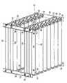
- FIG. 2is a front view of a skid package combining multiple PSA modules into a single unit according to the present invention
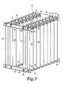
- FIG. 3is a front, left side perspective view of the unit of FIG. 2 ;
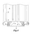
- FIG. 4is a partial, enlarged left side view of a secondary plate attached to bottom manifolds and used to tie multiple modules together to resist bending and racking;
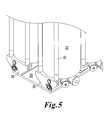
- FIG. 5is a partial, enlarged, front, left side perspective view of the secondary plate of FIG. 4 ;
- FIG. 6is an enlarged, cross-sectional view of a top manifold of the present invention.
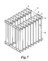
- FIG. 7is a front, left side perspective view of another embodiment of a skid package combining multiple PSA modules into a single unit according to the present invention.
- FIG. 8is a partial, enlarged, front, left side perspective view of the bottom secondary plate used to tie multiple modules together according to the embodiment of FIG. 7 ;
- FIG. 9is a partial, enlarged, front, left side perspective view of the top secondary plate used to tie multiple modules together according to the embodiment of FIG. 7 .
- FIG. 1depicts a pressure swing adsorption (PSA) module 1 with an array of eight vessels 2 extending between a bottom manifold 3 and a top manifold 4 .
- Integrated valves 5allow flow to be passed between vessels 2 in order to carry out the PSA process.
- FIG. 2a front view of an embodiment of a skid package combining multiple PSA modules 20 into a single unit 10 according to the present invention.
- the skid package of the present inventionallows for the use of PSA modules 20 configured for larger flows with larger diameter pressure vessels 22 , which result in longer bottom manifolds 30 and longer top manifolds 50 . While such an increase in dimensions of the pressure vessels 22 provides for greater processing capacity of the unit, such increases in dimensions of the module greatly increases the difficulty in supporting the mass of the module without engendering high stresses within the module. External support structures add cost and weight to the overall unit, and can disadvantageously reduce access to the PSA modules 20 for maintenance.
- the present inventionadvantageously uses the bottom manifold 30 and the top manifold 50 as horizontal, structural elements in combination with additional support members, and the large pressure vessels 22 as vertical, structural elements for providing greater structural integrity to the overall PSA skid package, particularly during shipment and handling without significantly increasing the cost or weight of the unit.
- FIG. 3depicts a front, left side view of the skid package of FIG. 2 combining multiple PSA modules 20 into a single unit according to the present invention.
- the skid packagewill combine multiple PSA modules 20 , and the accompanying control devices and distribution piping for the PSA modules. All other non-process specific pieces can be reduced to a minimum and will mainly include brackets and bracings that serve to tie the modules together in a way that takes advantage of the structural integrity of the modules 20 . Structural pieces running along the length of the modules are not necessary.
- the unit 10includes a pair of bottom horizontal braces 24 that extend essentially perpendicularly to the modules 20 and that are connected to opposing ends of the bottom manifolds 30 of each of the modules 20 .
- the unit 10also includes a pair of top horizontal braces 26 that extend essentially perpendicularly to the modules 20 and that are connected to opposing ends of the top manifolds 50 of each of the modules 20 .
- Such braces 24 , 26can be fixed directly to the manifolds 30 , 50 by bolts that extend through bolt holes 28 in the braces 24 , 26 and are threaded directly into end faces of the manifolds 30 , 50 .
- the braces 24 , 26can also support ancillary equipment, piping, electrical controls enclosures and their related brackets and support structure.
- the braces 24 , 26can be fixed to the end surfaces of the manifolds through a variety of methods including, but not limited to, welding, soldering, fasteners threaded into the manifolds, and fasteners that extend through all or part of the manifolds and require a nut.
- the bottom and top PSA manifolds 30 , 50may need to be constructed from special materials to combat corrosion from process gases. Such materials may suffer from low mechanical strength and/or high cost. Furthermore, such materials may not be manufactured in sufficient thickness to serve as adequate structural members.
- the present inventionadvantageously uses a support member, such as a support plate 29 , attached to one or more of the bottom manifolds to provide additional support during lifting, as can best be seen in FIGS. 4 and 5 .
- the support plate 29is attached to bottom surfaces of two bottom manifolds of two adjacent modules 20 .
- the support plate 29can be made of a different material than the material used to construct the manifolds, and therefore the use of a second material for the support plate can provide a support member made from a material having greater strength and/or lower cost than the manifold material.
- a bottom manifold 30manufactured from stainless steel
- a support plate 29manufactured from carbon or alloy steel.
- the support plate 29is attached to the bottom manifold 30 to form a composite beam with a greatly increased moment of inertia as compared to the manifold itself.
- the connection between the support plate 29 and the bottom manifold 30can be made with fasteners, adhesive, solder, braze, by welding, or by other means known in the art.
- One embodiment of the present inventionis contemplated in which the support plate 29 is made wider than the bottom manifold 30 and attached to a single manifold.
- FIGS. 4 and 5another embodiment of the present invention is contemplated in which the support plate 29 is attached to multiple bottom manifolds 30 and thus used to tie multiple modules 20 together to resist racking.
- the support plate 29can also be sized to reduce bearing loads between the PSA unit or plant and a foundation so that the bearing loads are below a maximum bearing stress thereof.
- a top support plate 27can also be attached to the top manifold 50 to increase the bending strength during lifting, and to provide the same advantages as the support plate 29 attached to the bottom manifold 30 .
- Such a top support plate 27can be used as a lifting feature only and then removed.
- One or more standardized top support platescan be used for lifting numerous PSA plants of the same design, thus the cost of the support plates can be advantageously reduced.
- the bottom support plates 29can also be used only as a transport fixture if desired, thereby optionally further reducing their cost.
- the modules 20 of the unit 10include a plurality of vertically extending elongated members such as tie rods 60 that are used to resist separating pressure forces and also provide further stabilization against racking during transport and handling.
- the tie rodsclamp the pressure vessels 22 between the bottom and top manifolds 30 , 50 in a manner that does not impose a bending moment to the pressure vessels 22 .
- the tie rods 60have a threaded bottom end 62 that is threaded into a hole on a bottom bracket 64 .
- the tie rods 60also have a threaded top end 66 that extends through a hole in a top bracket 68 and is provided with a threaded nut 67 on the top end 66 .
- Other retention meansare possible for the tie rods, including welding, swaging, etc.
- the top manifold 50incorporates a pressure relief device and a pressure relief manifolding device.
- the pressure relief devicecan include burst disks, spring-loaded valves, or any other pressure relief device.
- the pressure relief deviceis an inline, spring-return valve 51 .
- An example of such a valve 51is an ASME-certified inline, spring-return relief valve possessing one threaded end 52 .
- the top manifold 50is provided with an integral press-relief manifold channel 53 that is disposed parallel to three other channels 54 provided in the PSA manifold according to U.S. Pat. No.
- An inlet chamber 55is provided between the parallel channel 53 and the individual PSA vessel 22 , and provides fluid communication therebetween if the pressure relief device 51 is opened.
- the passage between the channel 53 and the inlet chamber 55is provided with a feature for receiving the pressure relief device 51 .
- the feature for receiving the pressure relief device 51is a threaded connection 56 .
- the feature for receiving the pressure relief device 51can alternatively be configured as a machined pocket for cartridge style valves, for pressed-fit installation, for adhesive bonding, or other means of installing a pressure relief device.
- the pressure relief device 51is preferably easily removed for inspection, repair, or replacement via a port 57 .
- the port 57which is provided between an outer surface of the top manifold 50 and the pressure relief device 51 , is made large enough for easy access.
- the port 57is provided with a sealing device, such as a plug 58 or cap.
- the top manifold described in U.S. Pat. No. 6,918,953advantageously provides the following advantages: collection of product from each vessel without additional piping; simultaneous ability to equalize between any two vessels without additional piping; and simultaneous ability to equalize or purge another set of vessels without additional piping.
- the present inventionprovides the following further advantages: mounting and collection of relief gas without piping; major component of structural integrity for entire plant; and easy integration with additional support structures.
- the bottom manifold described in U.S. Pat. No. 6,918,953advantageously provides the following advantages: distribution of feed to all vessels without additional piping; and collection of blowdown waste gas from all vessels without additional piping.
- the present inventionprovides the following further advantages: major component of structural integrity for entire plant; and easy integration with mounting plate and additional support structures.
- FIG. 7depicts a front, left side perspective view of another embodiment of a skid package combining multiple PSA modules into a single unit 10 according to the present invention.
- top support plates 70are provided that are attached to two adjacent modules.
- the top support plates 70are attached to the top manifolds 50 to increase the bending strength during lifting.
- the top support plates 70are provided with holes 72 in order to allow access during assembly and maintenance to features of the manifolds, such as plug 58 and port 57 .
- FIG. 9shows a partial, enlarged, front, left side perspective view of the top secondary plate 70 used to tie multiple modules together according to the embodiment of FIG. 7 , with the top horizontal braces removed and without access holes in the plate.
- FIG. 8depicts a partial, enlarged, front, left side perspective view of the bottom secondary plate 80 used to tie multiple modules together according to the embodiment of FIG. 7 , with the bottom horizontal braces removed.
- the bottom support plates 80are attached to the bottom manifolds 30 to increase the bending strength during lifting.
- the plurality of vertically extending tie rods 60are used to provide further stabilization.
- the tie rodsclamp the pressure vessels 22 between the bottom and top manifolds 30 , 50 in a manner that does not provide a bending moment to the pressure vessels 22 .
- the tie rods 60have a threaded bottom end 62 that is threaded into a hole on a bottom bracket 82 .
- the tie rods 60also have a threaded top end 66 that extends through a hole in a top bracket 74 and is provided with a threaded nut 67 on the top end 66 .
Landscapes
- Chemical & Material Sciences (AREA)
- Engineering & Computer Science (AREA)
- Analytical Chemistry (AREA)
- General Chemical & Material Sciences (AREA)
- Oil, Petroleum & Natural Gas (AREA)
- Chemical Kinetics & Catalysis (AREA)
- Fluid-Pressure Circuits (AREA)
- Supports For Pipes And Cables (AREA)
- Separation Of Gases By Adsorption (AREA)
Abstract
Description
Claims (29)
Priority Applications (5)
| Application Number | Priority Date | Filing Date | Title |
|---|---|---|---|
| US11/749,496US7763102B2 (en) | 2007-02-05 | 2007-05-16 | Pressure swing adsorption modules with integrated features |
| ES08728625TES2390084T3 (en) | 2007-02-05 | 2008-01-31 | Pressure swing adsorption modules with integrated features |
| PL08728625TPL2129450T3 (en) | 2007-02-05 | 2008-01-31 | Pressure swing adsorption modules with integrated features |
| EP08728625AEP2129450B1 (en) | 2007-02-05 | 2008-01-31 | Pressure swing adsorption modules with integrated features |
| PCT/US2008/052549WO2008097787A1 (en) | 2007-02-05 | 2008-01-31 | Pressure swing adsorption modules with integrated features |
Applications Claiming Priority (2)
| Application Number | Priority Date | Filing Date | Title |
|---|---|---|---|
| US88821007P | 2007-02-05 | 2007-02-05 | |
| US11/749,496US7763102B2 (en) | 2007-02-05 | 2007-05-16 | Pressure swing adsorption modules with integrated features |
Publications (2)
| Publication Number | Publication Date |
|---|---|
| US20080184890A1 US20080184890A1 (en) | 2008-08-07 |
| US7763102B2true US7763102B2 (en) | 2010-07-27 |
Family
ID=39675072
Family Applications (1)
| Application Number | Title | Priority Date | Filing Date |
|---|---|---|---|
| US11/749,496Expired - Fee RelatedUS7763102B2 (en) | 2007-02-05 | 2007-05-16 | Pressure swing adsorption modules with integrated features |
Country Status (5)
| Country | Link |
|---|---|
| US (1) | US7763102B2 (en) |
| EP (1) | EP2129450B1 (en) |
| ES (1) | ES2390084T3 (en) |
| PL (1) | PL2129450T3 (en) |
| WO (1) | WO2008097787A1 (en) |
Cited By (6)
| Publication number | Priority date | Publication date | Assignee | Title |
|---|---|---|---|---|
| US20120247573A1 (en)* | 2009-06-29 | 2012-10-04 | Lomax Jr Franklin D | Method and Manifold for Carrying Reduced Moment Due to Dimensional Change in Pressure Vessel; Removable Insert with Valve Seat; Pressure Assisted Valve Arrangement and Method |
| CN103402606A (en)* | 2011-03-01 | 2013-11-20 | 埃克森美孚上游研究公司 | Methods of removing contaminants from a hydrocarbon stream by swing adsorption and related apparatus and systems |
| US20140260991A1 (en)* | 2013-03-15 | 2014-09-18 | Invacare Corporation | Gas concentrator |
| US20150298045A1 (en)* | 2012-11-05 | 2015-10-22 | Nano-Porous Solutions Limited | Pressure swing adsorption apparatus |
| US20150298047A1 (en)* | 2012-11-29 | 2015-10-22 | Marco Pruneri | Machine for gas production |
| US10632415B2 (en)* | 2016-03-08 | 2020-04-28 | Biogts Green Energy Company Limited | Adsorption column set for separating two or more gases of a gas mixture from each other using pressure swing adsorption |
Families Citing this family (6)
| Publication number | Priority date | Publication date | Assignee | Title |
|---|---|---|---|---|
| CN102527188B (en)* | 2012-01-18 | 2013-09-18 | 龚涛 | Control method and system for pressure swing adsorption device |
| BE1020412A5 (en)* | 2012-04-18 | 2013-09-03 | Desotec Nv | DEVICE FOR PURIFYING POLLUTED AIR AND GASES. |
| GB2511357A (en)* | 2013-03-01 | 2014-09-03 | Walker Filtration Ltd | Banked purification system |
| FR3005874A1 (en)* | 2013-05-22 | 2014-11-28 | Nitrocraft | ADSORBER AND GENERATOR OF GAS COMPRISING SUCH AN ADSORBER |
| CN106237782A (en)* | 2016-08-22 | 2016-12-21 | 上海二十冶建设有限公司 | The modularity installation method of active carbon desulfurization denitration adsorption tower |
| EP3779133B1 (en)* | 2018-04-05 | 2023-07-19 | PURITECH Co., Ltd | Modular oxygen generator |
Citations (8)
| Publication number | Priority date | Publication date | Assignee | Title |
|---|---|---|---|---|
| US4802899A (en)* | 1987-09-21 | 1989-02-07 | Airsep Corporation | Pressure swing adsorption apparatus |
| US4983190A (en)* | 1985-05-21 | 1991-01-08 | Pall Corporation | Pressure-swing adsorption system and method for NBC collective protection |
| US5549736A (en)* | 1994-01-19 | 1996-08-27 | Litton Systems, Inc. | Modular, stackable pressure swing absorption concentrator |
| US5827354A (en)* | 1993-06-24 | 1998-10-27 | Carbotech-Anlagenbau Gmbh | Container for carbon molecular-sieve material |
| US20030188635A1 (en) | 2002-04-09 | 2003-10-09 | H2Gen Innovations, Inc. | Method and apparatus for pressure swing adsorption |
| US20040244584A1 (en) | 2003-06-04 | 2004-12-09 | H2Gen Innovations, Inc. | Flow control in pressure swing adsorption systems |
| US6858065B2 (en) | 2002-10-11 | 2005-02-22 | H2Gen Innovations, Inc. | High recovery PSA cycles and apparatus with reduced complexity |
| US6918953B2 (en) | 2003-07-09 | 2005-07-19 | H2Gen Innovations, Inc. | Modular pressure swing adsorption process and apparatus |
Family Cites Families (2)
| Publication number | Priority date | Publication date | Assignee | Title |
|---|---|---|---|---|
| US4559065A (en)* | 1984-03-15 | 1985-12-17 | Wilkerson Corporation | Twin tower gas fractionation apparatus |
| US5895570A (en)* | 1996-02-09 | 1999-04-20 | United States Filter Corporation | Modular filtering system |
- 2007
- 2007-05-16USUS11/749,496patent/US7763102B2/ennot_activeExpired - Fee Related
- 2008
- 2008-01-31PLPL08728625Tpatent/PL2129450T3/enunknown
- 2008-01-31WOPCT/US2008/052549patent/WO2008097787A1/enactiveApplication Filing
- 2008-01-31ESES08728625Tpatent/ES2390084T3/enactiveActive
- 2008-01-31EPEP08728625Apatent/EP2129450B1/ennot_activeNot-in-force
Patent Citations (8)
| Publication number | Priority date | Publication date | Assignee | Title |
|---|---|---|---|---|
| US4983190A (en)* | 1985-05-21 | 1991-01-08 | Pall Corporation | Pressure-swing adsorption system and method for NBC collective protection |
| US4802899A (en)* | 1987-09-21 | 1989-02-07 | Airsep Corporation | Pressure swing adsorption apparatus |
| US5827354A (en)* | 1993-06-24 | 1998-10-27 | Carbotech-Anlagenbau Gmbh | Container for carbon molecular-sieve material |
| US5549736A (en)* | 1994-01-19 | 1996-08-27 | Litton Systems, Inc. | Modular, stackable pressure swing absorption concentrator |
| US20030188635A1 (en) | 2002-04-09 | 2003-10-09 | H2Gen Innovations, Inc. | Method and apparatus for pressure swing adsorption |
| US6858065B2 (en) | 2002-10-11 | 2005-02-22 | H2Gen Innovations, Inc. | High recovery PSA cycles and apparatus with reduced complexity |
| US20040244584A1 (en) | 2003-06-04 | 2004-12-09 | H2Gen Innovations, Inc. | Flow control in pressure swing adsorption systems |
| US6918953B2 (en) | 2003-07-09 | 2005-07-19 | H2Gen Innovations, Inc. | Modular pressure swing adsorption process and apparatus |
Cited By (11)
| Publication number | Priority date | Publication date | Assignee | Title |
|---|---|---|---|---|
| US20120247573A1 (en)* | 2009-06-29 | 2012-10-04 | Lomax Jr Franklin D | Method and Manifold for Carrying Reduced Moment Due to Dimensional Change in Pressure Vessel; Removable Insert with Valve Seat; Pressure Assisted Valve Arrangement and Method |
| US8753428B2 (en)* | 2009-06-29 | 2014-06-17 | Lummus Technology Inc. | Method and manifold for carrying reduced moment due to dimensional change in pressure vessel; removable insert with valve seat; pressure assisted valve arrangement and method |
| CN103402606A (en)* | 2011-03-01 | 2013-11-20 | 埃克森美孚上游研究公司 | Methods of removing contaminants from a hydrocarbon stream by swing adsorption and related apparatus and systems |
| CN103402606B (en)* | 2011-03-01 | 2016-04-13 | 埃克森美孚上游研究公司 | The method of pollutant and relevant device and system is removed from hydrocarbon stream by becoming absorption |
| US20150298045A1 (en)* | 2012-11-05 | 2015-10-22 | Nano-Porous Solutions Limited | Pressure swing adsorption apparatus |
| US9844749B2 (en)* | 2012-11-05 | 2017-12-19 | Norgren Limited | Pressure swing adsorption apparatus |
| US20150298047A1 (en)* | 2012-11-29 | 2015-10-22 | Marco Pruneri | Machine for gas production |
| US9573092B2 (en)* | 2012-11-29 | 2017-02-21 | Marco Pruneri | Machine for gas production |
| US20140260991A1 (en)* | 2013-03-15 | 2014-09-18 | Invacare Corporation | Gas concentrator |
| US9061238B2 (en)* | 2013-03-15 | 2015-06-23 | Invacare Corporation | Gas concentrator |
| US10632415B2 (en)* | 2016-03-08 | 2020-04-28 | Biogts Green Energy Company Limited | Adsorption column set for separating two or more gases of a gas mixture from each other using pressure swing adsorption |
Also Published As
| Publication number | Publication date |
|---|---|
| US20080184890A1 (en) | 2008-08-07 |
| EP2129450B1 (en) | 2012-06-20 |
| WO2008097787A1 (en) | 2008-08-14 |
| PL2129450T3 (en) | 2012-11-30 |
| EP2129450A4 (en) | 2011-03-30 |
| EP2129450A1 (en) | 2009-12-09 |
| ES2390084T3 (en) | 2012-11-06 |
Similar Documents
| Publication | Publication Date | Title |
|---|---|---|
| US7763102B2 (en) | Pressure swing adsorption modules with integrated features | |
| JP4800938B2 (en) | Modular pressure swing adsorption process and apparatus | |
| KR102118860B1 (en) | Apparatus and system for associated swing adsorption process with multiple valves | |
| US8950433B2 (en) | Manifold system for gas and fluid delivery | |
| CA2592445C (en) | Methods and apparatus for improved control of psa flow variations | |
| US6929683B2 (en) | Method and apparatus for pressure swing adsorption | |
| US6436175B1 (en) | Adsorption apparatus | |
| US8152910B2 (en) | Modular gas-separating adsorbers | |
| CN114177741B (en) | A vacuum pressure swing adsorber for VPSA oxygen generator | |
| CN216909757U (en) | Novel modularized and standardized pressure swing adsorption nitrogen making equipment for light and small ships | |
| KR102843712B1 (en) | Systems and methods for assembling modules | |
| CN216457900U (en) | Adsorption tower assembly | |
| JPS6353862A (en) | Fuel cell gas supply and exhaust equipment | |
| CN115839162A (en) | Flower basket system of enclosure system construction platform module and installation process | |
| KR20130048027A (en) | Enclosed multi layer membrane module for hydrogen separation | |
| JP2005041758A (en) | Method and apparatus for producing nitrogen gas |
Legal Events
| Date | Code | Title | Description |
|---|---|---|---|
| AS | Assignment | Owner name:H2GEN INNOVATIONS, INC., VIRGINIA Free format text:ASSIGNMENT OF ASSIGNORS INTEREST;ASSIGNORS:LOMAX, FRANKLIN D., JR.;VAN DYKE, CHRISTOPHER;REEL/FRAME:019312/0375 Effective date:20070504 | |
| AS | Assignment | Owner name:LUMMUS TECHNOLOGY INC.,NEW JERSEY Free format text:ASSIGNMENT OF ASSIGNORS INTEREST;ASSIGNOR:H2GEN INNOVATIONS INC.;REEL/FRAME:023985/0817 Effective date:20100222 Owner name:LUMMUS TECHNOLOGY INC., NEW JERSEY Free format text:ASSIGNMENT OF ASSIGNORS INTEREST;ASSIGNOR:H2GEN INNOVATIONS INC.;REEL/FRAME:023985/0817 Effective date:20100222 | |
| STCF | Information on status: patent grant | Free format text:PATENTED CASE | |
| FPAY | Fee payment | Year of fee payment:4 | |
| MAFP | Maintenance fee payment | Free format text:PAYMENT OF MAINTENANCE FEE, 8TH YEAR, LARGE ENTITY (ORIGINAL EVENT CODE: M1552) Year of fee payment:8 | |
| FEPP | Fee payment procedure | Free format text:MAINTENANCE FEE REMINDER MAILED (ORIGINAL EVENT CODE: REM.); ENTITY STATUS OF PATENT OWNER: LARGE ENTITY | |
| LAPS | Lapse for failure to pay maintenance fees | Free format text:PATENT EXPIRED FOR FAILURE TO PAY MAINTENANCE FEES (ORIGINAL EVENT CODE: EXP.); ENTITY STATUS OF PATENT OWNER: LARGE ENTITY | |
| STCH | Information on status: patent discontinuation | Free format text:PATENT EXPIRED DUE TO NONPAYMENT OF MAINTENANCE FEES UNDER 37 CFR 1.362 | |
| FP | Lapsed due to failure to pay maintenance fee | Effective date:20220727 |