US7763058B2 - Device and method for photodynamic therapy of the nasopharyngeal cavity - Google Patents
Device and method for photodynamic therapy of the nasopharyngeal cavityDownload PDFInfo
- Publication number
- US7763058B2 US7763058B2US11/272,328US27232805AUS7763058B2US 7763058 B2US7763058 B2US 7763058B2US 27232805 AUS27232805 AUS 27232805AUS 7763058 B2US7763058 B2US 7763058B2
- Authority
- US
- United States
- Prior art keywords
- light
- treatment
- fluence
- guide tube
- nasopharyngeal
- Prior art date
- Legal status (The legal status is an assumption and is not a legal conclusion. Google has not performed a legal analysis and makes no representation as to the accuracy of the status listed.)
- Expired - Fee Related, expires
Links
Images


Classifications
- A—HUMAN NECESSITIES
- A61—MEDICAL OR VETERINARY SCIENCE; HYGIENE
- A61N—ELECTROTHERAPY; MAGNETOTHERAPY; RADIATION THERAPY; ULTRASOUND THERAPY
- A61N5/00—Radiation therapy
- A61N5/06—Radiation therapy using light
- A61N5/0601—Apparatus for use inside the body
- A61N5/0603—Apparatus for use inside the body for treatment of body cavities
- A61N2005/0607—Nose
- A—HUMAN NECESSITIES
- A61—MEDICAL OR VETERINARY SCIENCE; HYGIENE
- A61N—ELECTROTHERAPY; MAGNETOTHERAPY; RADIATION THERAPY; ULTRASOUND THERAPY
- A61N5/00—Radiation therapy
- A61N5/06—Radiation therapy using light
- A61N5/0601—Apparatus for use inside the body
- A—HUMAN NECESSITIES
- A61—MEDICAL OR VETERINARY SCIENCE; HYGIENE
- A61N—ELECTROTHERAPY; MAGNETOTHERAPY; RADIATION THERAPY; ULTRASOUND THERAPY
- A61N5/00—Radiation therapy
- A61N5/06—Radiation therapy using light
- A61N5/0613—Apparatus adapted for a specific treatment
- A61N5/062—Photodynamic therapy, i.e. excitation of an agent
Definitions
- the present inventionrelates to the field of photodynamic therapy and, in particular, to a device and method for controlled delivery of light to the nasopharyngeal cavity for the treatment of cancer.
- Photodynamic therapyis a minimally invasive, non-surgical treatment option for a variety of diseases, including cancer.
- PDTutilizes photosensitizing drugs and specific wavelengths of visible light to generate singlet oxygen, which in turn, induces oxidative damage in target tissues.
- the cumulative effects of oxidative damagenamely necrosis, apoptosis, and/or vascular collapse, result in the localized destruction of the target tissue.
- PDT treatmentresults in localized and specific tissue destruction, in part, because visible light has a tissue penetration range of between 2.0-6.0 mm.
- PDT treatmentsubstantially reduces trauma to underlying, healthy tissues and organs.
- PDTis an attractive alternative to other tumour therapies, such as chemotherapy and radiotherapy, especially when targeting cancerous tissues in the nasopharynx.
- nasopharyngeal cancerconsists of different combinations of chemotherapy and radiotherapy dosing regimes, which require high dose and high-precision techniques such as brachytherapy and stereotactic radiotherapy. These techniques deliver a maximum possible radiation dose to the nasopharyngeal cavity to limit damage to critical tissues such as the spinal cord, the optic nerve and the optical chiasma.
- this treatment schemeis time-consuming, technically demanding, and very stressful to the patient.
- Conventional radiotherapy methodsoften cause permanent radiation damage and unpleasant, long-term side effects. For example, xerostomia (dry mouth) is the result of permanent radiation damage to the salivary glands.
- PDTwould be an excellent alternative to surgery. Unlike conventional radiotherapy methods, PDT could provide effective treatment of superficial (surface) tumours without substantial risk to adjacent healthy tissues and organs. In addition, using PDT as a local booster could either supplement conventional radiotherapy or, in certain situations, completely supplant radiotherapy altogether.
- PDTFor effective destruction of target tissues, PDT requires uniform irradiation of the diseased tissue in the proper amount. Consequently, light intensity and light dose are critical factors to the overall efficacy of PDT treatments. But, PDT treatment in the nasopharyngeal cavity is problematic for two reasons: (1) light scattering and (2) the irregular geometry of the nasopharyngeal cavity. These two factors hamper the consistent delivery of a therapeutically effective light dose to the target tissue, which reduces the overall efficacy of PDT treatment.
- the interaction of light with biological tissueis a complicated process that changes with tissue type, fluence rate, delivered dose, and wavelength of light.
- Light dosimetry in PDT treatmentsis complicated by the light-tissue interaction process, which effectively increases the local light fluence rates and causing target tissues to receive a light dose that is many times higher than the original incoming light alone.
- Lundahl in U.S. Pat. No. 4,998,930entitled, “Intracavity Laser Phototherapy Method,” discloses another irradiation method especially suited for irradiating inside the human urinary bladder.
- Lundahlteaches a balloon catheter for centering a light source within the bladder prior to laser therapy.
- the disclosurefurther teaches a method of positioning a fiber optic light source in an irregularly shaped cavity that requires inflation of a balloon. Inflation of the balloon reshapes the cavity into a relatively uniform spherical shape thus allowing for uniform irradiation of tissue.
- RNARotterdam Nasopharynx Applicator developed by Levendag et al. for positioning catheters to deliver radioactive materials into the nasopharyngeal cavity in brachytherapy is discussed in Radiotherapy and Oncology, 1997; pp. 95-88.
- the RNAwas designed to accommodate the use of fractionated high dose radiation protocols on an out-patient basis.
- the RNAwas designed to remain in situ for the duration of the radiotherapy treatment which varies from 2 to 6 days.
- the RNAis not particularly suited for use in PDT treatment of the nasopharynx.
- referencesdisclose devices/methods optimized for the treatment of spatially straightforward cavities, i.e., closer to a spherical or a cylindrical shape.
- the fluence rate distribution at any point on the irradiated surfacecan be accurately predicted by measuring the fluence rate at a few select points.
- the nasopharynxis more spatially complex than either the spherically shaped bladder or the cylindrically shaped bronchi. This spatial complexity makes extrapolating the fluence rate distribution at any point in the nasopharynx from a small number of point measurements problematic at best.
- irradiation methods and deviceswhich are suitable for spherical or cylindrical cavities, do not offer stable and reproducible positioning in the nasopharynx together with uniform irradiation of nasopharyngeal target tissues.
- PDT treatments in the nasopharynxrequire a very different approach to choosing illumination parameters.
- the main setback for photodynamic therapy in the nasopharynxis the lack of a convenient, reproducible and controlled method for delivering light to the nasopharyngeal cavity.
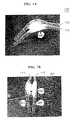
- Treatment within the nasopharyngeal cavitynecessitates the identification of“at risk” tissue areas as well as the treatment target area, which are determined beforehand using MR images or CT scans.
- This processis similar to the Planning Risk Volume (“PRV”) and Planning Target Volume (“PTV”) concepts used in radiotherapy planning.
- PRVPlanning Risk Volume
- PTVPlanning Target Volume
- uniform irradiationis critical for preventing under-exposure of diseased areas, as this would lead to recurrence of the tumour. Equally important is to prevent over-exposure of healthy or delicate tissues whose damage would lead to serious complications for the patient.
- the uniform illumination of the nasopharyngeal cavitythus requires a specialized device for use in PDT treatment in this area.
- the present device and methodaddress this need.
- It is another object of the inventionis to provide for the effective PDT treatment of superficial tumors in the nasopharynx without substantial risk to adjacent or underlying tissues and organs.
- the present inventionprovides a device/system and method for the delivery of light to the nasopharyngeal cavity in a controlled and reproducible manner using at least one optical fiber having a linear diffusing tip, a spherical diffusing tip, or a bare cut end.
- a positioning devicemay have one or two flexible guide tubes that are attached to a preformed shaped base that is introduced into the nasopharyngeal cavity to guide and position the optical fibers and/or detector(s).
- the optical fibersare enclosed within shielding tubes which are inserted into the guide tubes.
- the optical fibersmay be further moved within the shielding tube so as to adjust the amount of output light.
- a light detectorthat monitors, detects, and measures the delivery of fluence rates to pre-determined locations in the nasopharyngeal cavity.
- the detectormay also be enclosed within a separate tube within the guide tube.
- the inventive device/systemalso has a means of shielding pre-selected areas of the nasopharyngeal cavity or adjacent tissues from the light delivered by the optical fibers.
- the system of the present inventionuses a control unit and preselected treatment parameters to monitor, regulate, and display laser output and fluence rates at preselected locations in the nasopharyngeal cavity during PDT treatment.
- FIGS. 1A and 1Billustrate by different views the positioning means and guide tubes of the present invention.
- FIGS. 2A , 2 B and 2 Cillustrate by different views the device of FIG. 1 with the means for blocking light attached thereon as used in the present invention.
- FIGS. 3A and 3Billustrate the optical fiber within a shielding tube within the guide tube of the present invention.
- FIGS. 4A and 4Billustrate the detector with a shielding tube within the guide tube of the present invention.
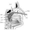
- FIG. 5illustrates the positioning of the inventive device within the nasopharyngeal cavity.
- FIG. 6illustrates a treatment situation using the inventive device within the nasopharyngeal cavity.
- FIGS. 7A and 7Billustrate the different means for measuring and detecting light according to the present invention.
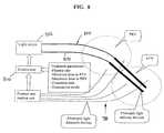
- FIG. 8is a schematic of the device and method of executing the treatment of the present invention.
- FIG. 9is a graph showing different fluence rates for different positions of the optical fiber output end of the present invention.
- the present inventiongenerally provides a device and method for the delivery of light to the nasopharyngeal cavity in a controlled and reproducible manner.
- the present inventionprovides for a positioning means for the stable and reproducible positioning of optical fibers in irregularly shaped cavities for the delivery of uniform illumination.
- the inventive positioning meansprovides for improved PDT treatment of disease in the nasopharynx.
- the present inventionprovides a system and method for delivering uniform illumination as well as controlling the manner and characteristics of illumination during PDT.
- FIG. 1Aillustrates the basic shape of positioning means 100 which guides the various optical fibers, FIG. 3 , and control components, FIG. 4 , into nasopharyngeal cavity 502 , FIG. 5 .
- positioning means 100is comprised of at least one hollow guide tube 102 or preferably, two hollow guide tubes 102 and 104 which are removably connected by a base 106 and holds guide tubes 102 and 104 in a predetermined position with respect to each other and the base 106 in the area of the nasopharynx and oropharynx.
- guide tubes 102 and 104form an opened “V” and from the front view in FIG. 1B , guide tubes 102 and 104 form a closed “V” with the apex truncated so as to provide output sections 108 and 110 .
- the configuration showedmay be modified based upon the patient's characteristics as determined by physical and x-ray examinations and other tests.
- the guide tubes 102 and 104may be extended so that output sections 108 and 110 need not occur at the ends of guide tubes 102 and 104 but refer to the position of the output ends of the optical fibers therein.
- the ends of guide tubes 102 and 104may fully extend and protrude from either the nose or the mouth or both thus providing several entrance means. It is therefore considered feasible that optical fibers or other components may be inserted into guide tubes 102 and 104 from either location, but preferably from the nose because of the shorter distance and few curves in the tubing.
- Base 106being the positioning means, may be made of a soft plastic material being either non-transparent or transparent to the light. In the preferred embodiment, a transparent base 106 is shown.
- Light blocking means 200is shown attached to guide tubes 102 and 104 .
- Light blocking means 200has the approximate shape of a stepped rectangular pad with a pair of holes 202 located at the upper end of the pad 200 as seen in FIG. 2B .
- the pad 200 as seen in FIG. 2is located on the side of nasopharynx mucosa, away from the palate.
- one side of pad 200is reflective, being light colored therein, and enhances the amount of light away from the reflective side.
- the pad 200may be on either side of the positioning means 100 as determined by the PRV (Planning Risk Volume). Further, pad 200 may be trimmed to fit a particular requirement so as to provide shielding of the underlying tissue from light emitted by the source optical fibers.
- PRVPlanning Risk Volume
- FIG. 3Aillustrates guide tubes 102 and 104 having therein optical fiber shielding tubes 300 and 302 with detector tubes 304 and 306 . Each tube being a hollow flexible tube.
- FIG. 3Billustrates guide tube 104 with shielding tube 300 .
- An optical fiber 308is inserted into the shielding tube 300 with a linear diffuser 310 .
- Other optical fiber output endsare feasible including siding firing. Attached to an appropriate position thereon, a positioning notch 305 determines the length of shielding tube 300 within guide tube 104 .
- Linear diffuser 310has two sections thereon which can change in length as determined by treatment parameters. As shown in FIG. 3B , an emitting section 312 of the diffuser 310 extends beyond shielding tube 300 which is non-transparent.
- Diffuser 310has a shielded section 314 which is within the non-transparent shielding tube 300 .
- the length of the optical fiber within the shielding tube 300By adjusting the length of the optical fiber within the shielding tube 300 , different amounts of light can be applied to the treatment area. If the full diffuser length is outside of the shielding tube 300 , a maximum is applied but in the configuration shown, a minimum of light is applied.
- FIG. 9illustrates the fluence rates for these different positions.
- FIG. 4Aillustrates the use of a detector shield tube 400 within guide tube 104 .
- a detector fiber 402Inside of the detector shield tube 400 is a detector fiber 402 having a detector element 404 that is appropriately positioned with guide tube 104 to measure, for example, fluence rate.
- the detector fiber 402 and the optical fiber 308may be inserted into the guide tube without protective tubes, the preferred embodiment has detector fiber 402 within detector shield tube 400 and optical fiber 308 within shielding tube 300 .
- the detector shield tube 400 and the optical fiber shielding tube 300being separate tubes within the guide tube 104 .
- FIG. 5illustrates the relative location of positioning means 100 after introduction into the nasopharynx cavity 502 of the respiratory system.
- positioning means 100is introduced into the nasopharyngeal cavity 502 using a two step approach. First, after applying local anesthesia, two silicone guide tubes 102 and 104 are inserted into nose 504 until the ends of the tubes 102 and 104 are visible in the oropharynx 506 . Next, using forceps, the now-visible ends are directed out through the mouth, while the distal ends remain protruding from the nose. Positioning means 100 of the present invention is then connected to the tubes exiting the mouth.
- Positioning means 100is introduced into the nasopharyngeal cavity by pulling on the distal ends of tubes 102 and 104 protruding from nose 504 . Using the above-described procedure, positioning means 100 enters through the mouth and is subsequently pulled into the nasopharyngeal cavity 502 until base 106 is in contact with nasal septum 508 . Additionally before the positioning means 100 is attached, pad 200 is attached to the guide tubes 102 and 104 through the two holes 202 .
- FIGS. 6 , 7 A and 7 Billustrate various treatment situations in accord with the present invention.
- FIG. 6illustrates an embodiment of the Planning Risk Volume, (PRV), 600 and the Planning Target Volume, (PTV), 602 which is located along the outer curve of the positioning means.
- PTV 602is defined as that area of tissue within the nasopharynx being treated.
- PRV 600would include all tissues, organs, etc., not with the area defined by PTV 602 .
- FIGS. 7A and 7Billustrate the use of positioning means 100 together with various means for measuring and detecting light within the nasopharynx.
- FIG. 7Aillustrates an embodiment in which detecting means 700 and 702 are introduced via the mouth.
- detecting means 700 and 702are positioned on PRV 600 and PTV 602 , respectively.
- FIG. 7Bshows another example of the positioning of detecting means 700 and 702 according to the present invention.
- detecting meansare positioned on the PTV 602 and the PRV 600 using the positioning means 100 of the present invention. It should be understood that the detecting means 700 and 702 were previously shown in greater detail in FIGS. 4A and 4B and that detector fiber 402 was inserted into a detector shield tube 400 which was within the guide tube 104 . This guide tube may be positioned through the nose or mouth or the detector fiber may be inserted without the guide tube from either location.
- control unit 800it is also preferred that the means for detecting and/or monitoring specific treatment parameters are also used to determine the operation of control unit 800 .
- these specific treatment parametersat least include: the desired fluence rate, and treatment time, the location/identity of the PTV and PRV, the minimum fluence to be delivered to the PTV, the maximum fluence to be delivered to the PRV and the choice which of the latter two is dominating the decision to terminate the treatment.
- control unit 800have means for controlling the optical power delivered to the fiberoptic light delivery devices according to measured fluence rates and calculated fluence rates so as to obtain a pre-selected fluence rate distribution. It is further preferred that the control unit have means for storing fluence rate data and for terminating illumination when the desired light dose has been delivered to one or more preselected locations.
- control unit 800monitors the signals from the fluence rate readout unit continuously.
- Control unit 800collects, calculates, and analyzes fluence rate values measured by the detecting means 700 with respect to preselected treatment parameters to control the delivery of light from laser light source 802 to the different fiberoptic light-delivery devices 804 and 806 .
- control unit 800controls total output as well as the energy distribution over the different light delivery fibers.
- Control unit 800also calculates and monitors the total fluence measured by the different detection fibers.
- Positioning means 100positions the various fiberoptic light-delivery devices 804 and 806 and detection means in a stable and reproducible manner.
- the readout unitprovides an on-going display of preselected treatment parameters or other relevant treatment data selected by the user.
- control unit 800has two possible modes of action when monitoring total fluence rates and that the operator chooses between these two modes before the treatment session begins.
- control unit 800will monitor and display the delivered fluences and continue the treatment until the preset minimum fluence to the PTV has been reached. However, in the first mode of operation control unit 800 breaks off the treatment prior to this if the preset maximum fluence to the PRV has been reached. This mode of operation intends to limit the damage to critical tissues such as the optic nerve or the soft palate, even at the risk of not completely treating the tumor.
- the first mode of operationis typically used in palliative treatment.
- the second mode of operationaims at curative treatment.
- control unit 800terminates the treatment only after the full preset fluence to the PTV has been delivered even if the delivered fluence to the PRV exceeds its maximum value.
- control unit 800when running in the second mode of operation, issues a warning message if the delivered fluence to the PRV has reached its preset maximum value and the delivered fluence to the PTV is not yet above its preset minimum value required for tumor eradication.
- the optionis given to terminate the treatment instantly. While the warning is ignored the treatment continues as planned and terminates as soon as the delivered fluence to the PTV reaches its preset minimum value, accepting over-treatment in the PRV.
Landscapes
- Health & Medical Sciences (AREA)
- Engineering & Computer Science (AREA)
- Biomedical Technology (AREA)
- Pathology (AREA)
- Nuclear Medicine, Radiotherapy & Molecular Imaging (AREA)
- Radiology & Medical Imaging (AREA)
- Life Sciences & Earth Sciences (AREA)
- Animal Behavior & Ethology (AREA)
- General Health & Medical Sciences (AREA)
- Public Health (AREA)
- Veterinary Medicine (AREA)
- Radiation-Therapy Devices (AREA)
Abstract
Description
Claims (7)
Priority Applications (3)
| Application Number | Priority Date | Filing Date | Title |
|---|---|---|---|
| US11/272,328US7763058B2 (en) | 2004-11-20 | 2005-11-10 | Device and method for photodynamic therapy of the nasopharyngeal cavity |
| AU2005305606AAU2005305606B2 (en) | 2004-11-20 | 2005-11-17 | Device and method for photodynamic therapy of the nasopharyngeal cavity |
| KR1020077013855AKR101277642B1 (en) | 2004-11-20 | 2005-11-17 | Device and method for photodynamic therapy of the nasopharyngeal cavity |
Applications Claiming Priority (2)
| Application Number | Priority Date | Filing Date | Title |
|---|---|---|---|
| US62976504P | 2004-11-20 | 2004-11-20 | |
| US11/272,328US7763058B2 (en) | 2004-11-20 | 2005-11-10 | Device and method for photodynamic therapy of the nasopharyngeal cavity |
Publications (2)
| Publication Number | Publication Date |
|---|---|
| US20060111762A1 US20060111762A1 (en) | 2006-05-25 |
| US7763058B2true US7763058B2 (en) | 2010-07-27 |
Family
ID=35821171
Family Applications (1)
| Application Number | Title | Priority Date | Filing Date |
|---|---|---|---|
| US11/272,328Expired - Fee RelatedUS7763058B2 (en) | 2004-11-20 | 2005-11-10 | Device and method for photodynamic therapy of the nasopharyngeal cavity |
Country Status (6)
| Country | Link |
|---|---|
| US (1) | US7763058B2 (en) |
| EP (1) | EP1824562B1 (en) |
| CN (1) | CN101128237B (en) |
| AT (1) | ATE513582T1 (en) |
| CA (1) | CA2591086C (en) |
| WO (1) | WO2006054179A1 (en) |
Cited By (10)
| Publication number | Priority date | Publication date | Assignee | Title |
|---|---|---|---|---|
| US10357661B2 (en) | 2011-09-30 | 2019-07-23 | Percuvision, Llc | Medical device and method for internal healing and antimicrobial purposes |
| US11147984B2 (en) | 2020-03-19 | 2021-10-19 | Know Bio, Llc | Illumination devices for inducing biological effects |
| US11524173B2 (en) | 2015-07-28 | 2022-12-13 | Know Bio, Llc | Systems and methods for phototherapeutic modulation of nitric oxide |
| US11654294B2 (en) | 2021-03-15 | 2023-05-23 | Know Bio, Llc | Intranasal illumination devices |
| US11986666B2 (en) | 2020-03-19 | 2024-05-21 | Know Bio, Llc | Illumination devices for inducing biological effects |
| US12011611B2 (en) | 2020-03-19 | 2024-06-18 | Know Bio, Llc | Illumination devices for inducing biological effects |
| US12029914B2 (en) | 2015-07-28 | 2024-07-09 | Know Bio, Llc | Phototherapeutic light for treatment of pathogens |
| US12115384B2 (en) | 2021-03-15 | 2024-10-15 | Know Bio, Llc | Devices and methods for illuminating tissue to induce biological effects |
| US12347337B2 (en) | 2020-12-10 | 2025-07-01 | Know Bio, Llc | Enhanced testing and characterization techniques for phototherapeutic light treatments |
| US12440697B2 (en) | 2023-03-09 | 2025-10-14 | Know Bio, Llc | Systems and methods for phototherapeutic modulation of nitric oxide |
Families Citing this family (8)
| Publication number | Priority date | Publication date | Assignee | Title |
|---|---|---|---|---|
| US8109981B2 (en) | 2005-01-25 | 2012-02-07 | Valam Corporation | Optical therapies and devices |
| WO2007145614A2 (en)* | 2006-06-08 | 2007-12-21 | Eremia Sorin M D | Suture instrument and method of suturing in cosmetic surgery |
| US11344742B2 (en)* | 2015-07-23 | 2022-05-31 | Health Research, Inc. | System and method for administering light therapy to curved and large surfaces |
| RU179822U1 (en)* | 2017-06-30 | 2018-05-24 | Зродников Владимир Сергеевич | Photodynamic device for distant irradiation of the mucous membrane of the nasopharynx |
| DE102017120949A1 (en) | 2017-09-11 | 2019-03-14 | Marc-Eric Halatsch | implant system |
| EP3617731A1 (en)* | 2018-08-29 | 2020-03-04 | Erasmus University Medical Center Rotterdam | Magnetic resonance imaging based on transient response signals |
| CN111773549A (en)* | 2020-07-02 | 2020-10-16 | 中山旦邦光电科技有限公司 | a light therapy device |
| WO2024096911A1 (en)* | 2022-11-05 | 2024-05-10 | Lumeda Inc. | Pdt bend-tolerant light delivery device and dosimetry method |
Citations (16)
| Publication number | Priority date | Publication date | Assignee | Title |
|---|---|---|---|---|
| US3664330A (en)* | 1969-09-12 | 1972-05-23 | Harold L Deutsch | Fiber optic medical tool |
| GB2057886A (en) | 1979-09-12 | 1981-04-08 | Pucholt V | Apparatus for use in diagnosis |
| US4269192A (en) | 1977-12-02 | 1981-05-26 | Olympus Optical Co., Ltd. | Stabbing apparatus for diagnosis of living body |
| US4449535A (en) | 1981-03-25 | 1984-05-22 | Compagnie Industrielle Des Lasers Cilas Alcatel | Apparatus for measuring in situ the state of oxidation-reduction of a living organ |
| US4576168A (en)* | 1983-01-05 | 1986-03-18 | Jalowayski Alfredo A | Nasal dilator |
| US4998930A (en) | 1988-08-03 | 1991-03-12 | Phototherapeutic Systems | Intracavity laser phototherapy method |
| EP0467432A1 (en) | 1990-07-20 | 1992-01-22 | Laica Laser Technology Ventures B.V. | Device for detecting air in the pleural cavity |
| US5400771A (en)* | 1993-01-21 | 1995-03-28 | Pirak; Leon | Endotracheal intubation assembly and related method |
| US5445608A (en)* | 1993-08-16 | 1995-08-29 | James C. Chen | Method and apparatus for providing light-activated therapy |
| US5590660A (en)* | 1994-03-28 | 1997-01-07 | Xillix Technologies Corp. | Apparatus and method for imaging diseased tissue using integrated autofluorescence |
| US5803080A (en) | 1995-12-20 | 1998-09-08 | Willy Rusch Ag | Instrument for interventional flexible tracheoscopy/bronchoscopy |
| US5814041A (en)* | 1992-03-20 | 1998-09-29 | The General Hospital Corporation | Laser illuminator |
| US5997571A (en) | 1997-12-17 | 1999-12-07 | Cardiofocus, Inc. | Non-occluding phototherapy probe stabilizers |
| US6513527B1 (en) | 2000-06-13 | 2003-02-04 | University Of Mississippi Medical Center | Bibronchial double lumen tube |
| US20040030368A1 (en)* | 2001-08-10 | 2004-02-12 | Lajos Kemeny | Phototherapeutical method and system for the treatment of inflammatory and hyperproliferative disorders of the nasal mucosa |
| US20060271024A1 (en)* | 2005-01-25 | 2006-11-30 | Michael Gertner | Nasal Cavity Treatment Apparatus |
Family Cites Families (5)
| Publication number | Priority date | Publication date | Assignee | Title |
|---|---|---|---|---|
| JP3551996B2 (en)* | 1995-08-25 | 2004-08-11 | 松下電器産業株式会社 | Medical laser probe |
| US6146409A (en)* | 1996-05-20 | 2000-11-14 | Bergein F. Overholt | Therapeutic methods and devices for irradiating columnar environments |
| GB2323284B (en)* | 1997-03-19 | 2001-01-03 | Rusch Mfg | Device for photodynamic therapy of pituitary tumours |
| US6159236A (en)* | 1999-01-28 | 2000-12-12 | Advanced Photodynamic Technologies, Inc. | Expandable treatment device for photodynamic therapy and method of using same |
| DE60139132D1 (en)* | 2001-11-23 | 2009-08-13 | Nucletron Bv | Device for radiotherapy in a human or animal body |
- 2005
- 2005-11-10USUS11/272,328patent/US7763058B2/ennot_activeExpired - Fee Related
- 2005-11-17WOPCT/IB2005/003726patent/WO2006054179A1/enactiveApplication Filing
- 2005-11-17ATAT05812188Tpatent/ATE513582T1/ennot_activeIP Right Cessation
- 2005-11-17CNCN2005800445682Apatent/CN101128237B/ennot_activeExpired - Fee Related
- 2005-11-17CACA2591086Apatent/CA2591086C/ennot_activeExpired - Fee Related
- 2005-11-17EPEP05812188Apatent/EP1824562B1/ennot_activeNot-in-force
Patent Citations (17)
| Publication number | Priority date | Publication date | Assignee | Title |
|---|---|---|---|---|
| US3664330A (en)* | 1969-09-12 | 1972-05-23 | Harold L Deutsch | Fiber optic medical tool |
| US4269192A (en) | 1977-12-02 | 1981-05-26 | Olympus Optical Co., Ltd. | Stabbing apparatus for diagnosis of living body |
| GB2057886A (en) | 1979-09-12 | 1981-04-08 | Pucholt V | Apparatus for use in diagnosis |
| US4449535A (en) | 1981-03-25 | 1984-05-22 | Compagnie Industrielle Des Lasers Cilas Alcatel | Apparatus for measuring in situ the state of oxidation-reduction of a living organ |
| US4576168A (en)* | 1983-01-05 | 1986-03-18 | Jalowayski Alfredo A | Nasal dilator |
| US4998930A (en) | 1988-08-03 | 1991-03-12 | Phototherapeutic Systems | Intracavity laser phototherapy method |
| EP0467432A1 (en) | 1990-07-20 | 1992-01-22 | Laica Laser Technology Ventures B.V. | Device for detecting air in the pleural cavity |
| US5814041A (en)* | 1992-03-20 | 1998-09-29 | The General Hospital Corporation | Laser illuminator |
| US5400771A (en)* | 1993-01-21 | 1995-03-28 | Pirak; Leon | Endotracheal intubation assembly and related method |
| US5445608A (en)* | 1993-08-16 | 1995-08-29 | James C. Chen | Method and apparatus for providing light-activated therapy |
| US5590660A (en)* | 1994-03-28 | 1997-01-07 | Xillix Technologies Corp. | Apparatus and method for imaging diseased tissue using integrated autofluorescence |
| US5827190A (en)* | 1994-03-28 | 1998-10-27 | Xillix Technologies Corp. | Endoscope having an integrated CCD sensor |
| US5803080A (en) | 1995-12-20 | 1998-09-08 | Willy Rusch Ag | Instrument for interventional flexible tracheoscopy/bronchoscopy |
| US5997571A (en) | 1997-12-17 | 1999-12-07 | Cardiofocus, Inc. | Non-occluding phototherapy probe stabilizers |
| US6513527B1 (en) | 2000-06-13 | 2003-02-04 | University Of Mississippi Medical Center | Bibronchial double lumen tube |
| US20040030368A1 (en)* | 2001-08-10 | 2004-02-12 | Lajos Kemeny | Phototherapeutical method and system for the treatment of inflammatory and hyperproliferative disorders of the nasal mucosa |
| US20060271024A1 (en)* | 2005-01-25 | 2006-11-30 | Michael Gertner | Nasal Cavity Treatment Apparatus |
Non-Patent Citations (1)
| Title |
|---|
| Levendag, P.C., A new applicatgor design for endocavitary brackytherapy of cancer in the nasopharynx, Radiotherapy and Oncology, 1997, 95-98, Elsevier, Ireland. |
Cited By (17)
| Publication number | Priority date | Publication date | Assignee | Title |
|---|---|---|---|---|
| US10357661B2 (en) | 2011-09-30 | 2019-07-23 | Percuvision, Llc | Medical device and method for internal healing and antimicrobial purposes |
| US12397169B2 (en) | 2015-07-28 | 2025-08-26 | Know Bio, Llc | Phototherapeutic light for treatment of pathogens |
| US11524173B2 (en) | 2015-07-28 | 2022-12-13 | Know Bio, Llc | Systems and methods for phototherapeutic modulation of nitric oxide |
| US11617895B2 (en) | 2015-07-28 | 2023-04-04 | Know Bio, Llc | Systems and methods for phototherapeutic modulation of nitric oxide |
| US12179035B2 (en) | 2015-07-28 | 2024-12-31 | Know Bio, Llc | Phototherapeutic light for treatment of pathogens |
| US12109429B2 (en) | 2015-07-28 | 2024-10-08 | Know Bio, Llc | Phototherapeutic light for treatment of pathogens |
| US12029914B2 (en) | 2015-07-28 | 2024-07-09 | Know Bio, Llc | Phototherapeutic light for treatment of pathogens |
| US12011611B2 (en) | 2020-03-19 | 2024-06-18 | Know Bio, Llc | Illumination devices for inducing biological effects |
| US11986666B2 (en) | 2020-03-19 | 2024-05-21 | Know Bio, Llc | Illumination devices for inducing biological effects |
| US11752359B2 (en) | 2020-03-19 | 2023-09-12 | Know Bio, Llc | Illumination devices for inducing biological effects |
| US11684798B2 (en) | 2020-03-19 | 2023-06-27 | Know Bio, Llc | Illumination devices for inducing biological effects |
| US12390657B2 (en) | 2020-03-19 | 2025-08-19 | Know Bio, Llc | Illumination devices for inducing biological effects |
| US11147984B2 (en) | 2020-03-19 | 2021-10-19 | Know Bio, Llc | Illumination devices for inducing biological effects |
| US12347337B2 (en) | 2020-12-10 | 2025-07-01 | Know Bio, Llc | Enhanced testing and characterization techniques for phototherapeutic light treatments |
| US12115384B2 (en) | 2021-03-15 | 2024-10-15 | Know Bio, Llc | Devices and methods for illuminating tissue to induce biological effects |
| US11654294B2 (en) | 2021-03-15 | 2023-05-23 | Know Bio, Llc | Intranasal illumination devices |
| US12440697B2 (en) | 2023-03-09 | 2025-10-14 | Know Bio, Llc | Systems and methods for phototherapeutic modulation of nitric oxide |
Also Published As
| Publication number | Publication date |
|---|---|
| CA2591086C (en) | 2013-11-05 |
| EP1824562A1 (en) | 2007-08-29 |
| CN101128237B (en) | 2011-07-06 |
| EP1824562B1 (en) | 2011-06-22 |
| CA2591086A1 (en) | 2006-05-26 |
| ATE513582T1 (en) | 2011-07-15 |
| US20060111762A1 (en) | 2006-05-25 |
| WO2006054179A1 (en) | 2006-05-26 |
| CN101128237A (en) | 2008-02-20 |
Similar Documents
| Publication | Publication Date | Title |
|---|---|---|
| US7763058B2 (en) | Device and method for photodynamic therapy of the nasopharyngeal cavity | |
| JP5188510B2 (en) | Fiber optic phototherapy equipment | |
| US6159236A (en) | Expandable treatment device for photodynamic therapy and method of using same | |
| DK1973598T3 (en) | Apparatus for light-activated drug therapy | |
| JP3648555B2 (en) | Improved phototherapy device for irradiating a columnar environment | |
| JP4122323B2 (en) | Balloon catheter for photodynamic therapy | |
| EP1896122B1 (en) | Tissue treatment device | |
| US6048359A (en) | Spatial orientation and light sources and method of using same for medical diagnosis and photodynamic therapy | |
| EP0719571B1 (en) | Medical apparatus | |
| US9149651B2 (en) | Non-invasive vascular treatment systems, devices, and methods of using the same | |
| GB2390545A (en) | Hollow organ probe | |
| IL100545A (en) | Apparatus for photodynamic therapy treatment | |
| JP7511293B2 (en) | Needle Laser Therapy System | |
| Marijnissen et al. | Pilot study on light dosimetry for endobronchial photodynamic therapy | |
| EP3325096B1 (en) | System for delivering dosed light to tissue | |
| JP5702529B2 (en) | Medical light irradiation device | |
| Overholt et al. | A centering balloon for photodynamic therapy of esophageal cancer tested in a canine model | |
| JP2023527680A (en) | Time multiple dosimetry system and method | |
| AU2005305606B2 (en) | Device and method for photodynamic therapy of the nasopharyngeal cavity | |
| CN112107801A (en) | Optical fiber probe for laser therapy | |
| RU2196623C2 (en) | Method for treating malignant tumors | |
| WO2008076986A1 (en) | Methods and devices for controllable phototherapy | |
| Hirschberg et al. | An indwelling brachytherapy balloon catheter: potential use as an intracranial light applicator for photodynamic therapy | |
| CA3227079A1 (en) | Configurable photodynamic therapy system and method | |
| Maier et al. | In vivo determination of tumor optical parameters in esophageal carcinoma |
Legal Events
| Date | Code | Title | Description |
|---|---|---|---|
| AS | Assignment | Owner name:BIOLITEC PHARMA MARKETING LTD., MALAYSIA Free format text:ASSIGNMENT OF ASSIGNORS INTEREST;ASSIGNOR:BIOLITEC, INC.;REEL/FRAME:022482/0944 Effective date:20090331 Owner name:BIOLITEC, INC., MASSACHUSETTS Free format text:ASSIGNMENT OF ASSIGNORS INTEREST;ASSIGNOR:CERAMOPTEC INDUSTRIES, INC.;REEL/FRAME:022482/0956 Effective date:20090330 Owner name:BIOLITEC PHARMA MARKETING LTD.,MALAYSIA Free format text:ASSIGNMENT OF ASSIGNORS INTEREST;ASSIGNOR:BIOLITEC, INC.;REEL/FRAME:022482/0944 Effective date:20090331 Owner name:BIOLITEC, INC.,MASSACHUSETTS Free format text:ASSIGNMENT OF ASSIGNORS INTEREST;ASSIGNOR:CERAMOPTEC INDUSTRIES, INC.;REEL/FRAME:022482/0956 Effective date:20090330 | |
| REMI | Maintenance fee reminder mailed | ||
| FPAY | Fee payment | Year of fee payment:4 | |
| SULP | Surcharge for late payment | ||
| AS | Assignment | Owner name:BIOLITEC UNTERNEHMENSBETEILIGUNGS II AG, AUSTRIA Free format text:ASSIGNMENT OF ASSIGNORS INTEREST;ASSIGNOR:BIOLITEC PHARMA MARKETING LTD.;REEL/FRAME:041182/0578 Effective date:20160308 | |
| FEPP | Fee payment procedure | Free format text:MAINTENANCE FEE REMINDER MAILED (ORIGINAL EVENT CODE: REM.) | |
| LAPS | Lapse for failure to pay maintenance fees | Free format text:PATENT EXPIRED FOR FAILURE TO PAY MAINTENANCE FEES (ORIGINAL EVENT CODE: EXP.); ENTITY STATUS OF PATENT OWNER: SMALL ENTITY | |
| STCH | Information on status: patent discontinuation | Free format text:PATENT EXPIRED DUE TO NONPAYMENT OF MAINTENANCE FEES UNDER 37 CFR 1.362 | |
| FP | Lapsed due to failure to pay maintenance fee | Effective date:20180727 |