US7763018B2 - Cool-tip thermocouple including two-piece hub - Google Patents
Cool-tip thermocouple including two-piece hubDownload PDFInfo
- Publication number
- US7763018B2 US7763018B2US11/495,033US49503306AUS7763018B2US 7763018 B2US7763018 B2US 7763018B2US 49503306 AUS49503306 AUS 49503306AUS 7763018 B2US7763018 B2US 7763018B2
- Authority
- US
- United States
- Prior art keywords
- chamber
- electrode assembly
- ablation electrode
- assembly
- lumen
- Prior art date
- Legal status (The legal status is an assumption and is not a legal conclusion. Google has not performed a legal analysis and makes no representation as to the accuracy of the status listed.)
- Active, expires
Links
Images


Classifications
- A—HUMAN NECESSITIES
- A61—MEDICAL OR VETERINARY SCIENCE; HYGIENE
- A61B—DIAGNOSIS; SURGERY; IDENTIFICATION
- A61B18/00—Surgical instruments, devices or methods for transferring non-mechanical forms of energy to or from the body
- A—HUMAN NECESSITIES
- A61—MEDICAL OR VETERINARY SCIENCE; HYGIENE
- A61B—DIAGNOSIS; SURGERY; IDENTIFICATION
- A61B18/00—Surgical instruments, devices or methods for transferring non-mechanical forms of energy to or from the body
- A61B18/04—Surgical instruments, devices or methods for transferring non-mechanical forms of energy to or from the body by heating
- A61B18/12—Surgical instruments, devices or methods for transferring non-mechanical forms of energy to or from the body by heating by passing a current through the tissue to be heated, e.g. high-frequency current
- A61B18/14—Probes or electrodes therefor
- A61B18/1477—Needle-like probes
- A—HUMAN NECESSITIES
- A61—MEDICAL OR VETERINARY SCIENCE; HYGIENE
- A61B—DIAGNOSIS; SURGERY; IDENTIFICATION
- A61B18/00—Surgical instruments, devices or methods for transferring non-mechanical forms of energy to or from the body
- A61B2018/00005—Cooling or heating of the probe or tissue immediately surrounding the probe
- A61B2018/00011—Cooling or heating of the probe or tissue immediately surrounding the probe with fluids
- A61B2018/00023—Cooling or heating of the probe or tissue immediately surrounding the probe with fluids closed, i.e. without wound contact by the fluid
Definitions
- the present disclosurerelates to electrode thermosurgery systems and, more particularly, to cool-tip ablation electrode systems used for thermosurgery procedures and the like.
- Radio-frequencyRF
- Other forms of energyhave been accomplished for many decades using radio-frequency (RF) and other forms of energy.
- RF ablation needle electrodesusually of elongated cylindrical geometry
- a typical form of such needle electrodesincorporates an insulated sheath from which an exposed (uninsulated) tip extends.
- RF ablation electrode systemshave incorporated temperature sensors, for example, in the form of a thermistor or thermocouple.
- temperature sensorsfor example, in the form of a thermistor or thermocouple.
- the sensoris connected to a monitoring apparatus for indicating temperature to assist in accomplishing a desired lesion.
- a monitoring apparatusfor indicating temperature to assist in accomplishing a desired lesion.
- a limitation of prior electrode ablation systemsrelates to the temperature of the tip. Specifically, prior needle electrodes of a given tip geometry never should effectively exceed a temperature of 100° C. At that temperature, the surrounding tissue will boil and char. Also, uncontrolled disruption, such as hemorrhage and explosive gas formation, may cause extremely hazardous and clinically dangerous effects on the patient. Consequently, the lesion size for a given electrode geometry generally has been considered to be somewhat limited by the fact that the tissue near the tip must not exceed 100° C.
- the needle electrode temperatureis highest near the tip, because the current density is the highest at that location. Accordingly, temperature falls off as a function of distance from the tip of the needle electrode, and except for possible abnormalities in tissue conductivity and so on, in a somewhat predictable and even calculable pattern. As an attendant consequence, the size of RF lesions for a given electrode geometry have been somewhat limited.
- the present disclosurerelates to ablation electrode systems used for thermosurgery procedures and the like.
- an ablation electrode systemfor use with a source of electrosurgical energy to ablate tissue in a living subject.
- the ablation electrode systemincludes a handle assembly; and a needle electrode assembly supported in and extending from the handle assembly.
- the needle electrode assemblyincludes an outer tube having at least a conductive distal tip, a proximal end portion supported in the handle assembly, and defining a cavity therein; and an inner tube disposed at least partially within the cavity of the outer tube and having a proximal end portion supported within the handle assembly, the inner tube defining a lumen therein.
- the ablation electrode systemfurther includes a hub assembly supported within the handle assembly and fluidly connected to the needle electrode assembly.
- the hub assemblyincludes an outer shell defining a lumen therein; and an inner manifold operatively supported in the lumen of the outer shell.
- the inner manifold and the outer shellare configured and dimensioned so as to define a first chamber and a second chamber therebetween.
- the proximal end portion of the inner tubeis in fluid communication with the first chamber and the proximal end portion of the outer tube is in fluid communication with the second chamber.
- the ablation electrode systemfurther includes an electrical conduit electrically connected to the outer tube of the needle electrode assembly; a first fluid conduit fluidly connected to the first chamber; and a second fluid conduit fluidly connected to the second chamber.
- an ablation electrode systemincludes a handle assembly; a needle electrode assembly supported in and extending from the handle assembly.
- the needle electrode assemblyincludes an outer tube having at least a conductive distal tip, a proximal end portion supported in the handle assembly, and defining a cavity therein; and an inner tube disposed at least partially within the cavity of the outer tube and having a proximal end portion supported within the handle assembly, the inner tube defining a lumen therein.
- the ablation electrode assemblyincludes a hub assembly supported within the handle assembly and fluidly connected to the needle electrode assembly.
- the hub assemblydefines a first chamber and a second chamber; wherein the proximal end portion of the inner tube is in fluid communication with the first chamber and the proximal end portion of the outer tube is in fluid communication with the second chamber.
- the ablation electrode assemblyincludes an electrical conduit electrically connected to the outer tube of the needle electrode assembly; a first fluid conduit fluidly connected to the first chamber; and a second fluid conduit fluidly connected to the second chamber.
- an ablation system for ablating tissue in a living subjectincludes an ablation electrode system including a needle electrode assembly.
- the needle electrode assemblyincludes an outer tube having at least a conductive distal tip and defining a cavity therein; and an inner tube disposed at least partially within the cavity of the outer tube and defining a lumen therein.
- the ablation electrode systemfurther includes a hub assembly fluidly connected to the needle electrode assembly.
- the hub assemblydefines a first chamber and a second chamber; wherein a proximal end portion of the inner tube is in fluid communication with the first chamber and a proximal end portion of the outer tube is in fluid communication with the second chamber.
- the ablation systemincludes a source of electrosurgical energy; a source of fluid; an electrical conduit electrically interconnecting the outer tube of the needle electrode assembly and the source of electrosurgical energy; a first fluid conduit fluidly interconnecting the source of fluid and the first chamber; and a second fluid conduit fluidly connected to the second chamber.
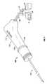
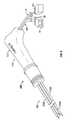
- FIG. 1is a perspective view of an ablation electrode system in accordance with an embodiment of the present disclosure
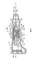
- FIG. 2is an enlarged perspective view of the ablation electrode system of FIG. 1 , with a handle half-section removed therefrom and a hub assembly disposed therein shown partially broken away;
- FIG. 3is a longitudinal cross-sectional view of the ablation electrode system of FIGS. 1 and 2 ;
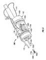
- FIG. 4is an enlarged longitudinal cross-sectional view of the hub assembly of FIGS. 2 and 3 ;
- FIG. 5is a longitudinal cross-sectional view of the outer shell of the hub assembly of FIGS. 2-4 , including a needle electrode shown operative connected thereto;
- FIG. 6is a perspective view an inner manifold of the hub assembly of FIGS. 2-4 ;
- FIG. 7is a longitudinal cross-sectional view of the inner manifold of FIG. 6 ;
- FIG. 8is a perspective view of an ablation electrode system according to an alternate embodiment of the present disclosure.
- FIG. 9is a longitudinal cross-sectional view of the ablation electrode system of FIG. 8 ;
- FIG. 10is a longitudinal cross-sectional view of the outer shell of the hub assembly of FIG. 9 , including needle electrodes shown operative connected thereto;
- FIG. 10Ais a distal end view of the outer shell of the hub assembly of the ablation electrode system of FIG. 8 ;
- FIG. 11is a perspective view an inner manifold of the hub assembly of FIG. 9 ;
- FIG. 12is a longitudinal cross-sectional view of the inner manifold of FIG. 11 ;
- FIG. 13is a perspective view of an ablation electrode system illustrating a strain relief member operatively associated therewith for support of the cables and/or conduits entering the handle;
- FIG. 14is a schematic perspective view of a strain relief member for use with ablation electrode system
- FIG. 15is a schematic longitudinal cross-sectional view of another strain relief member shown supported in the handle of the ablation electrode system
- FIG. 16is a schematic longitudinal cross-sectional view of yet another strain relief member shown supported in the handle of the ablation electrode system
- FIG. 17is a schematic perspective view of another strain relief member for use with ablation electrode system.
- FIG. 18is a cross-sectional view of the strain relief member of FIG. 17 , as taken through 18 - 18 of FIG. 17 .
- proximalrefers to the end of the instrument, apparatus or device that is closer to the user and the term “distal” refers to the end of the apparatus that is further away from the user.
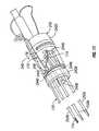
- an electrode ablation systemis generally designated as ablation system 100 .
- Ablation system 100includes a housing or handle assembly 110 , and at least one needle electrode assembly 150 supported within and extending from housing assembly 110 .
- Housing assembly 110 and needle electrode assembly 150define a central longitudinal axis “X”.
- housing assembly 110includes a housing or handle 112 having first half-section 112 a and a second half-section 112 b selectively connectable to one another (e.g., in a snap-fit manner) via connecting structure 114 or the like.
- housing 112has a substantially conical shape defining a flattened proximal surface 116 a and a flattened distal surface 116 b ( FIGS. 2 and 3 ).
- Housing 112further includes an annular ramp-like structure 116 c extending from the surface thereof. Ramp-like structure 116 c acts as a surface against which an operators fingers contact for distal advancement of needle electrode 150 into the patient and/or proximal withdrawal of needle electrode 150 from the patient.
- electrode ablation system 100further includes a hub assembly 120 supported in housing 112 of housing assembly 110 .
- Hub assemblyincludes a hub assembly outer shell 130 and a hub assembly inner manifold 140 disposed within outer shell 130 .
- Outer shell 130 and inner manifold 140 of hub assemblyare each fabricated from a suitable electrically non-conductive material.
- hub assembly outer shell 130includes a body portion 132 defining a central lumen 134 extending therethrough.
- Outer shell 130defines a central longitudinal axis “X 1 ” extending through central lumen 134 .
- Central lumen 134 of outer shell 130includes a tapered distal end 136 defining a constricted passage 134 a therethrough. Passage 134 a is sized to support and receive needle electrode assembly 150 therein.
- Body portion 132 of outer shell 130may include an annular flange 138 formed therearound. As seen in FIGS. 2 and 3 , annular flange 138 of outer shell 130 is receiveable in a complementary annular channel or groove 118 formed or provided in housing 112 . Accordingly, annular flange 138 and annular groove 118 cooperate to fix the location of hub assembly 120 relative to housing 112 .
- inner manifold 140is configured and dimensioned for support within lumen 134 of outer shell 130 .
- Inner manifold 140includes a body portion 142 defining a first or inflow lumen 144 a formed at least partially in a proximal end portion 142 b thereof.
- Inner manifold 140further includes a second or outflow lumen 144 b extending entirely therethrough.
- Inner manifold 140further includes a third lumen 144 c formed at least partially in a distal end portion 142 a thereof.
- inner manifold 140defines a first recess 148 formed therein such that when inner manifold 140 is inserted into lumen 134 of outer shell 130 , first recess 148 defines a first cavity or chamber 122 between outer shell 130 and inner manifold 140 .
- first lumen 144 a and third lumen 144 care each in fluid communication with first chamber 122 .
- a second chamber 124is defined in tapered distal end 136 of outer shell 130 .
- second lumen 144 b of manifold 140is in fluid communication with the second chamber 124 .
- body portion 142 of inner manifold 140may include an annular groove 142 a formed therein.
- annular groove 142 a of body portion 142 of inner manifold 140is configured and dimensioned to receive a complementary annular flange or rib 128 formed in body portion 132 of outer shell 130 . Accordingly, annular flange 128 and annular groove 142 c cooperate to fix the location of inner manifold 140 relative to outer shell 130 .
- a glue “G”including and not limited to, adhesives, epoxies, bonding agents, cements, silicones and the like, is applied in a proximal or rear portion of lumen 134 of outer shell 130 , on a proximal or rear surface of inner manifold 140 , and at locations therebetween.
- Glue “G”functions to further secure inner manifold 140 within outer shell 130 and to create a seal between outer shell 130 and inner manifold 140 to thereby inhibit and/or prevent the escape of fluid from therebetween.
- hub assembly 120includes a seal element 126 (e.g., an O-ring) disposed between body portion 132 of outer shell 130 and body portion 142 of inner manifold 140 .
- Seal element 126functions to reduce and/or prevent fluid from traveling between first chamber 122 and second chamber 124 .
- a first or in-flow conduit 10is fluidly connected to first lumen 144 a of inner manifold 140 .
- a distal end of first conduit 10extends through housing 112 of housing assembly 110 and is frictionally inserted into first lumen 144 a of inner manifold 140 of hub assembly 120 .
- a second or out-flow conduit 20is fluidly connected to second lumen 144 b of inner manifold 140 .
- a distal end of second conduit 20extends through housing 112 of housing assembly 110 and is frictionally inserted into second lumen 144 b of inner manifold 140 of hub assembly 120 .
- Needle electrode assembly 150includes an outer tube 152 a having an exposed distal end portion 154 a terminating in a sharpened distal tip 156 a which is constructed so as to penetrate tissue with a minimum risk of hemorrhage from the puncture tract.
- Outer tube 152 ais constructed from a suitable electrically conductive material.
- Outer tube 152 aincludes a proximal end portion 158 a supported in housing 112 , and in an embodiment, in a distal lumen 134 b formed in and extending distally from constricted passage 134 a of outer shell 130 , as seen in FIGS. 4 and 5 .
- Outer tube 152 ais hollow and defines a cavity 160 a therein.
- the non-exposed part of outer tube 152 amay be surrounded by a suitable insulating material.
- the insulating materialmay be any material which is biologically acceptable and suitable for insertion into tissue. Since distal end portion 154 a is exposed or non-insulated, distal end portion 154 a is capable of DC or AC delivery, preferably RF delivery.
- Needle electrode assembly 150further includes an inner tube 152 b disposed substantially co-axially within cavity 160 a of outer tube 152 a .
- Inner tube 152 bincludes a distal end portion 156 b (see FIGS. 6 and 7 ) located near distal end portion 154 a of outer tube 152 a and a proximal end portion 158 b extending from proximal end portion 158 a of outer tube 152 a .
- Proximal end portion 158 b of inner tube 152 bextends through constricted passage 134 a and into or through third lumen 144 c of inner manifold 140 . It is envisioned that proximal end portion 158 b of inner tube 152 b is in fluid communication with first cavity or chamber 122 defined between inner manifold 140 and outer shell 130 , see FIGS. 2-4 .
- cooling fluid “F”is delivered to distal tip 156 a of outer tube 152 a from in-flow conduit 10 .
- cooling fluid “F”travels from in-flow conduit 10 , into first chamber 122 , into lumen 160 b (see FIGS. 6 and 7 ) of inner tube 152 b of needle electrode assembly 150 , to distal tip 156 a of outer tube 152 a .
- Cooling fluid “F”is led away from distal tip 156 a of outer tube 152 a through cavity 160 a , through second chamber 124 , through second lumen 144 b of inner manifold 140 , and out through out-flow tube 20 .
- Cooling fluid “F”may be communicated to a collecting container (not shown) or back to a source of fluid “SF” (see FIG. 1 ) for re-circulation. Circulation of cooling fluid “F” may be established with the use of a suitable pump (not explicitly shown).
- electrode ablation system 100further includes a first electrical conduit 170 extending through housing 112 and electrically connected to outer tube 152 a of needle electrode assembly 150 .
- first electrical conduit 170includes a distal end 170 a electrically connected to outer tube 152 a at a location distal of hub assembly 120 and within housing 112 .
- First electrical conduit 170is also electrically connected to a source of electrosurgical energy “E”. Accordingly, electrosurgical energy may be delivered from the source of electrosurgical energy, through first electrical conduit 170 , to outer tube 152 a.
- electrode ablation system 100further includes a thermocouple assembly 172 operatively associated with inner tube 152 b .
- Thermocouple assembly 172includes a first wire or thermocouple 174 extending through lumen 160 b of inner tube 152 b .
- a distal end 174 a of first wire 174is desirably electrically secured to distal end portion 156 b of inner tube 152 b , as by, for example, soldering and the like.
- First wire 174may be fabricated from constantan (i.e., a high-resistance alloy of approximately 40% nickel and 60% copper). However, other suitable materials may be used for first wire 174 , such as, for example, any suitable conductor that is dissimilar from inner tube 152 b (e.g., stainless steel) such that a thermocouple is created between the two materials.
- Thermocouple assembly 172further includes a second wire 176 having a distal end 176 a electrically connected to inner tube 152 b .
- distal end 176 a of second wire 176is connected to a proximal end portion 158 b of inner tube 152 b .
- Second wire 176functions to electrically interconnect first wire 174 and a thermocouple measuring circuit. Accordingly, a temperature measurement signal from the thermocouple measuring circuit may then be sent to an electrosurgical energy source “E” and/or a central processing unit for monitoring.
- each of electrical conduit 170 , first wire 174 and second wire 176may be contained in a single cable 180 .
- Electrode ablation system 200is substantially similar to ablation system 100 and will be discussed in detail to the extent necessary to identify differences in construction and operation. Unlike electrode ablation system 100 , which includes a single needle electrode assembly 150 , electrode ablation system 200 includes three needle electrode assemblies 250 a - 250 c extending distally from housing 112 of housing assembly 110 . While a single and three needle electrode assemblies have been shown and described herein, any suitable number of needle electrode assemblies may be provided.
- hub assembly 220 of electrode ablation system 200includes a hub assembly outer shell 130 and a hub assembly inner manifold 240 operatively disposed within outer shell 230 .
- hub assembly outer shell 230includes a body portion 232 defining a central lumen 234 extending therethrough.
- outer shell 230includes three constricted passages 236 a - 236 c extending through a distal end portion 230 a of outer shell 230 and in fluid communication with central lumen 234 .
- each passage 236 a - 236 cis sized to support and receive a proximal end of outer tube 252 a of a respective needle electrode assembly 250 a - 250 c.
- inner manifold 240is configured and dimensioned for support within lumen 234 of outer shell 230 .
- Inner manifold 240includes a body portion 242 defining a first or inflow lumen 244 a formed at least partially in a proximal end portion 242 b thereof.
- Inner manifold 240further includes a second or outflow lumen 244 b extending entirely therethrough.
- Inner manifold 240further includes a plurality of third lumens 244 c formed at least partially in a distal end portion thereof 242 a .
- Each third lumen 244 c of inner manifold 240is configured and dimensioned to receive and support a proximal end of a respective inner tube 252 b of needle electrode assemblies 250 a - 250 c therein.
- inner manifold 240defines a first recess 248 formed therein such that when inner manifold 240 is inserted into lumen 234 of outer shell 230 , first recess 248 defines a first cavity or chamber 222 between outer shell 230 and inner manifold 240 .
- first lumen 244 a and each third lumen 244 care in fluid communication with first chamber 222 .
- a second chamber 224is defined in distal end portion 236 of lumen 234 of outer shell 230 .
- second lumen 244 b of manifold 240is in fluid communication with the second chamber 224 .
- each needle electrode assembly 250 a - 250 c of electrode ablation system 200is substantially similar to needle electrode assembly 150 of electrode ablation system 100 , and therefore reference may be made to the detailed discussion of needle electrode assembly 150 for an understanding and description of needle electrode assemblies 250 a - 250 c.
- cooling fluid “F”is delivered to a distal tip 256 of each outer tube 252 a .
- cooling fluidtravels from in-flow conduit 10 , into first chamber 222 , into a lumen of an inner tube (see FIGS. 6 and 7 ) of each needle electrode assembly 250 a - 250 c , to a distal tip 256 of the outer tube of each needle electrode assembly 250 a - 250 c .
- the cooling fluidis led away from distal tip 256 of the outer tube of each needle electrode assembly 250 a - 250 c , through second chamber 224 , through second lumen 244 b of inner manifold 240 , and out through out-flow tube 20 .
- thermocouple assembly 172extends through lumen 160 b (see FIG. 6 ) of at least one inner tube 252 b of needle electrode assemblies 250 a - 250 c .
- a distal end 174 a of first wire 174is desirably electrically secured to a distal end portion of inner tube 252 b , as by, for example, soldering and the like.
- first wire 174is fabricated from constantan or the like (i.e., a high-resistance alloy of approximately 40% nickel and 60% copper).
- a second wire 176 of thermocouple assembly 172has a distal end electrically connected to inner tube 252 b.
- the handle of needle electrode system 200is configured and adapted so as to maintain needle electrode assemblies 250 a - 250 c substantially parallel to one another during insertion and/or placement of needle electrode assemblies 250 a - 250 c into a target surgical site.
- electrode ablation systems 100 , 200may each include an adjustable cord strain relief member 50 operatively disposed on cable 180 , in-flow conduit 10 , and/or out-flow conduit 20 .
- Strain relief member 50is configured and dimensioned for operative engagement in an aperture 114 (see FIGS. 1 and 2 ) of housing 112 of handle assembly 110 .
- aperture 114is formed in a side of housing 112 of handle assembly 110 such that cable 180 , in-flow conduit 10 and/or out-flow conduit 20 may extend out of the side thereof.
- Strain relief member 50includes a body portion 52 having a substantially hour-glass configuration.
- Body portion 52may include a first substantially spherical portion 52 a and a second substantially spherical portion 52 b .
- second portion 52 b of body portion 52is poly-axially supported (e.g., in the manner of a ball and socket joint) within a complementarily sized and shaped aperture 114 .
- annular rib 54 amay be provided on the surface of second body portion 52 a for engaging the inner surface of shaped aperture 114 .
- Strain relief member 50may also be provided with a shield or apron 56 extending radially therefrom. Shield 56 may be disposed within an appropriately sized recess 116 formed in handle 112 , as seen in FIG. 15 , or may be disposed externally of handle 112 , as seen in FIG. 16 .
- strain relief member 50may include means for locking including a tapered portion 52 c disposed between first body portion 52 a and second body portion 52 b , and at least one longitudinally oriented locking rib 54 b projecting from tapered portion 52 c .
- Locking rib 54 bis configured and dimensioned to selectively engage complementary channels 118 formed in handle 112 .
- first directionas indicated by arrow “A”
- second directionopposite to direction “A”
- locking rib 54 bengages channels 118 to lock strain relief member 50 .
Landscapes
- Health & Medical Sciences (AREA)
- Surgery (AREA)
- Life Sciences & Earth Sciences (AREA)
- Engineering & Computer Science (AREA)
- Biomedical Technology (AREA)
- Otolaryngology (AREA)
- Nuclear Medicine, Radiotherapy & Molecular Imaging (AREA)
- Heart & Thoracic Surgery (AREA)
- Medical Informatics (AREA)
- Molecular Biology (AREA)
- Animal Behavior & Ethology (AREA)
- General Health & Medical Sciences (AREA)
- Public Health (AREA)
- Veterinary Medicine (AREA)
- Plasma & Fusion (AREA)
- Physics & Mathematics (AREA)
- Surgical Instruments (AREA)
Abstract
Description
Claims (26)
Priority Applications (3)
| Application Number | Priority Date | Filing Date | Title |
|---|---|---|---|
| US11/495,033US7763018B2 (en) | 2006-07-28 | 2006-07-28 | Cool-tip thermocouple including two-piece hub |
| US12/182,723US8672937B2 (en) | 2006-07-28 | 2008-07-30 | Cool-tip thermocouple including two-piece hub |
| US14/193,114US9848932B2 (en) | 2006-07-28 | 2014-02-28 | Cool-tip thermocouple including two-piece hub |
Applications Claiming Priority (1)
| Application Number | Priority Date | Filing Date | Title |
|---|---|---|---|
| US11/495,033US7763018B2 (en) | 2006-07-28 | 2006-07-28 | Cool-tip thermocouple including two-piece hub |
Related Child Applications (1)
| Application Number | Title | Priority Date | Filing Date |
|---|---|---|---|
| US12/182,723DivisionUS8672937B2 (en) | 2006-07-28 | 2008-07-30 | Cool-tip thermocouple including two-piece hub |
Publications (2)
| Publication Number | Publication Date |
|---|---|
| US20080027424A1 US20080027424A1 (en) | 2008-01-31 |
| US7763018B2true US7763018B2 (en) | 2010-07-27 |
Family
ID=38987295
Family Applications (3)
| Application Number | Title | Priority Date | Filing Date |
|---|---|---|---|
| US11/495,033Active2028-03-03US7763018B2 (en) | 2006-07-28 | 2006-07-28 | Cool-tip thermocouple including two-piece hub |
| US12/182,723Active2028-09-11US8672937B2 (en) | 2006-07-28 | 2008-07-30 | Cool-tip thermocouple including two-piece hub |
| US14/193,114Active2026-08-14US9848932B2 (en) | 2006-07-28 | 2014-02-28 | Cool-tip thermocouple including two-piece hub |
Family Applications After (2)
| Application Number | Title | Priority Date | Filing Date |
|---|---|---|---|
| US12/182,723Active2028-09-11US8672937B2 (en) | 2006-07-28 | 2008-07-30 | Cool-tip thermocouple including two-piece hub |
| US14/193,114Active2026-08-14US9848932B2 (en) | 2006-07-28 | 2014-02-28 | Cool-tip thermocouple including two-piece hub |
Country Status (1)
| Country | Link |
|---|---|
| US (3) | US7763018B2 (en) |
Cited By (22)
| Publication number | Priority date | Publication date | Assignee | Title |
|---|---|---|---|---|
| US20100292686A1 (en)* | 2004-10-08 | 2010-11-18 | Rick Kyle R | Cool-Tip Combined Electrode Introducer |
| US8007493B2 (en) | 2006-10-16 | 2011-08-30 | Syneron Medical Ltd. | Methods and devices for treating tissue |
| US20110224504A1 (en)* | 2010-03-11 | 2011-09-15 | Tyco Healthcare Group Lp | Automated Probe Placement Device |
| US8133216B2 (en) | 2006-10-16 | 2012-03-13 | Syneron Medical Ltd. | Methods and devices for treating tissue |
| US8142426B2 (en)* | 2006-10-16 | 2012-03-27 | Syneron Medical Ltd. | Methods and devices for treating tissue |
| US20120215214A1 (en)* | 2007-09-07 | 2012-08-23 | Tyco Healthcare Group Lp | Cool Tip Junction |
| US8273080B2 (en) | 2006-10-16 | 2012-09-25 | Syneron Medical Ltd. | Methods and devices for treating tissue |
| US8480666B2 (en) | 2007-01-31 | 2013-07-09 | Covidien Lp | Thermal feedback systems and methods of using the same |
| US9757197B2 (en) | 2009-10-06 | 2017-09-12 | Angiodynamics, Inc. | Medical devices and pumps therefor |
| US9757196B2 (en) | 2011-09-28 | 2017-09-12 | Angiodynamics, Inc. | Multiple treatment zone ablation probe |
| US9770295B2 (en) | 2003-06-23 | 2017-09-26 | Angiodynamics, Inc. | Radiation applicator for microwave medical treatment |
| US9848932B2 (en)* | 2006-07-28 | 2017-12-26 | Covidien Ag | Cool-tip thermocouple including two-piece hub |
| US9888956B2 (en) | 2013-01-22 | 2018-02-13 | Angiodynamics, Inc. | Integrated pump and generator device and method of use |
| US9895189B2 (en) | 2009-06-19 | 2018-02-20 | Angiodynamics, Inc. | Methods of sterilization and treating infection using irreversible electroporation |
| US10660691B2 (en) | 2015-10-07 | 2020-05-26 | Angiodynamics, Inc. | Multiple use subassembly with integrated fluid delivery system for use with single or dual-lumen peristaltic tubing |
| US11707629B2 (en) | 2009-05-28 | 2023-07-25 | Angiodynamics, Inc. | System and method for synchronizing energy delivery to the cardiac rhythm |
| US11723710B2 (en) | 2016-11-17 | 2023-08-15 | Angiodynamics, Inc. | Techniques for irreversible electroporation using a single-pole tine-style internal device communicating with an external surface electrode |
| US11931096B2 (en) | 2010-10-13 | 2024-03-19 | Angiodynamics, Inc. | System and method for electrically ablating tissue of a patient |
| US12102376B2 (en) | 2012-02-08 | 2024-10-01 | Angiodynamics, Inc. | System and method for increasing a target zone for electrical ablation |
| US12114911B2 (en) | 2014-08-28 | 2024-10-15 | Angiodynamics, Inc. | System and method for ablating a tissue site by electroporation with real-time pulse monitoring |
| US12201349B2 (en) | 2009-04-03 | 2025-01-21 | Angiodynamics, Inc. | Congestive obstruction pulmonary disease (COPD) |
| USD1084316S1 (en) | 2023-11-20 | 2025-07-15 | Angiodynamics, Inc. | Ferrule |
Families Citing this family (23)
| Publication number | Priority date | Publication date | Assignee | Title |
|---|---|---|---|---|
| US7553309B2 (en) | 2004-10-08 | 2009-06-30 | Covidien Ag | Electrosurgical system employing multiple electrodes and method thereof |
| US7282049B2 (en)* | 2004-10-08 | 2007-10-16 | Sherwood Services Ag | Electrosurgical system employing multiple electrodes and method thereof |
| US20070066971A1 (en)* | 2005-09-21 | 2007-03-22 | Podhajsky Ronald J | Method and system for treating pain during an electrosurgical procedure |
| US7879031B2 (en)* | 2005-09-27 | 2011-02-01 | Covidien Ag | Cooled RF ablation needle |
| US20070078454A1 (en)* | 2005-09-30 | 2007-04-05 | Mcpherson James W | System and method for creating lesions using bipolar electrodes |
| US20070078453A1 (en)* | 2005-10-04 | 2007-04-05 | Johnson Kristin D | System and method for performing cardiac ablation |
| US20070258838A1 (en)* | 2006-05-03 | 2007-11-08 | Sherwood Services Ag | Peristaltic cooling pump system |
| US20070260240A1 (en)* | 2006-05-05 | 2007-11-08 | Sherwood Services Ag | Soft tissue RF transection and resection device |
| US9486269B2 (en)* | 2007-06-22 | 2016-11-08 | Covidien Lp | Electrosurgical systems and cartridges for use therewith |
| US8292880B2 (en) | 2007-11-27 | 2012-10-23 | Vivant Medical, Inc. | Targeted cooling of deployable microwave antenna |
| US8343149B2 (en)* | 2008-06-26 | 2013-01-01 | Vivant Medical, Inc. | Deployable microwave antenna for treating tissue |
| US8608739B2 (en) | 2008-07-22 | 2013-12-17 | Covidien Lp | Electrosurgical devices, systems and methods of using the same |
| US20100256735A1 (en)* | 2009-04-03 | 2010-10-07 | Board Of Regents, The University Of Texas System | Intraluminal stent with seam |
| US8672938B2 (en) | 2009-07-23 | 2014-03-18 | Covidien Lp | Active cooling system and apparatus for controlling temperature of a fluid used during treatment of biological tissue |
| US8469953B2 (en)* | 2009-11-16 | 2013-06-25 | Covidien Lp | Twin sealing chamber hub |
| US9579150B2 (en) | 2011-04-08 | 2017-02-28 | Covidien Lp | Microwave ablation instrument with interchangeable antenna probe |
| KR101248959B1 (en)* | 2011-05-12 | 2013-04-01 | 신경민 | Electrode device having flexible tube for high frequency thermotherapy |
| KR101522662B1 (en)* | 2013-11-27 | 2015-05-27 | 주식회사 스타메드 | An electrode device for a high frequency treatment |
| US9687292B2 (en) | 2015-05-31 | 2017-06-27 | I.C. Medical, Inc. | Electrosurgery handpiece/pencil with smoke evacuation |
| CN116919562B (en)* | 2023-08-08 | 2024-08-13 | 融和医疗科技(浙江)有限公司 | Oral cavity ablation device |
| WO2025030700A1 (en)* | 2023-08-08 | 2025-02-13 | 融和医疗科技(浙江)有限公司 | Pulse ablation device and ablation device for oral cavity |
| CN119174645B (en)* | 2024-11-26 | 2025-09-16 | 上海方润医疗科技股份有限公司 | Ablation electrode device with improved handle internal structure |
| CN119174644B (en)* | 2024-11-26 | 2025-09-05 | 上海方润医疗科技股份有限公司 | Ablation electrode device with optimized internal structure of handle |
Citations (136)
| Publication number | Priority date | Publication date | Assignee | Title |
|---|---|---|---|---|
| US4074718A (en) | 1976-03-17 | 1978-02-21 | Valleylab, Inc. | Electrosurgical instrument |
| DE2407559C3 (en) | 1974-02-16 | 1982-01-21 | Dornier System Gmbh, 7990 Friedrichshafen | Heat probe |
| US4375220A (en) | 1980-05-09 | 1983-03-01 | Matvias Fredrick M | Microwave applicator with cooling mechanism for intracavitary treatment of cancer |
| US4411266A (en) | 1980-09-24 | 1983-10-25 | Cosman Eric R | Thermocouple radio frequency lesion electrode |
| US4565200A (en) | 1980-09-24 | 1986-01-21 | Cosman Eric R | Universal lesion and recording electrode system |
| US4576177A (en) | 1983-02-18 | 1986-03-18 | Webster Wilton W Jr | Catheter for removing arteriosclerotic plaque |
| US4608977A (en) | 1979-08-29 | 1986-09-02 | Brown Russell A | System using computed tomography as for selective body treatment |
| US4662383A (en) | 1982-09-27 | 1987-05-05 | Kureha Kagaku Kogyo Kabushiki Kaisha | Endotract antenna device for hyperthermia |
| EP0246350A1 (en) | 1986-05-23 | 1987-11-25 | Erbe Elektromedizin GmbH. | Coagulation electrode |
| US4739759A (en) | 1985-02-26 | 1988-04-26 | Concept, Inc. | Microprocessor controlled electrosurgical generator |
| US4832024A (en) | 1986-04-29 | 1989-05-23 | Georges Boussignac | Cardio-vascular catheter for shooting a laser beam |
| US4880719A (en) | 1987-07-03 | 1989-11-14 | Fuji Xerox Co., Ltd. | Two component electrophotographic developer |
| US4961435A (en) | 1987-10-28 | 1990-10-09 | Kureha Kagaku Kogyo Kabushiki Kaishi | High-frequency capacitive heating electrode device |
| US4966597A (en) | 1988-11-04 | 1990-10-30 | Cosman Eric R | Thermometric cardiac tissue ablation electrode with ultra-sensitive temperature detection |
| US4993430A (en) | 1987-01-06 | 1991-02-19 | Omron Tateisi Electronics Co. | Electrode device for high frequency thermotherapy apparatus |
| US5029588A (en) | 1989-06-15 | 1991-07-09 | Cardiovascular Imaging Systems, Inc. | Laser catheter with imaging capability |
| US5103804A (en) | 1990-07-03 | 1992-04-14 | Boston Scientific Corporation | Expandable tip hemostatic probes and the like |
| US5225741A (en) | 1989-03-10 | 1993-07-06 | Bruce Industries, Inc. | Electronic ballast and power controller |
| US5230623A (en) | 1991-12-10 | 1993-07-27 | Radionics, Inc. | Operating pointer with interactive computergraphics |
| US5233515A (en) | 1990-06-08 | 1993-08-03 | Cosman Eric R | Real-time graphic display of heat lesioning parameters in a clinical lesion generator system |
| US5246438A (en) | 1988-11-25 | 1993-09-21 | Sensor Electronics, Inc. | Method of radiofrequency ablation |
| US5267994A (en) | 1992-02-10 | 1993-12-07 | Conmed Corporation | Electrosurgical probe |
| US5281213A (en) | 1992-04-16 | 1994-01-25 | Implemed, Inc. | Catheter for ice mapping and ablation |
| US5323778A (en) | 1991-11-05 | 1994-06-28 | Brigham & Women's Hospital | Method and apparatus for magnetic resonance imaging and heating tissues |
| US5330518A (en) | 1992-03-06 | 1994-07-19 | Urologix, Inc. | Method for treating interstitial tissue associated with microwave thermal therapy |
| US5334193A (en) | 1992-11-13 | 1994-08-02 | American Cardiac Ablation Co., Inc. | Fluid cooled ablation catheter |
| US5342357A (en) | 1992-11-13 | 1994-08-30 | American Cardiac Ablation Co., Inc. | Fluid cooled electrosurgical cauterization system |
| US5348554A (en) | 1992-12-01 | 1994-09-20 | Cardiac Pathways Corporation | Catheter for RF ablation with cooled electrode |
| EP0310431B1 (en) | 1987-09-30 | 1994-11-02 | Valleylab, Inc. | Apparatus for providing enhanced tissue fragmentation and/or hemostasis |
| US5370675A (en) | 1992-08-12 | 1994-12-06 | Vidamed, Inc. | Medical probe device and method |
| US5383876A (en) | 1992-11-13 | 1995-01-24 | American Cardiac Ablation Co., Inc. | Fluid cooled electrosurgical probe for cutting and cauterizing tissue |
| US5383917A (en) | 1991-07-05 | 1995-01-24 | Jawahar M. Desai | Device and method for multi-phase radio-frequency ablation |
| US5385148A (en) | 1993-07-30 | 1995-01-31 | The Regents Of The University Of California | Cardiac imaging and ablation catheter |
| US5403311A (en) | 1993-03-29 | 1995-04-04 | Boston Scientific Corporation | Electro-coagulation and ablation and other electrotherapeutic treatments of body tissue |
| US5409000A (en) | 1993-09-14 | 1995-04-25 | Cardiac Pathways Corporation | Endocardial mapping and ablation system utilizing separately controlled steerable ablation catheter with ultrasonic imaging capabilities and method |
| US5409006A (en) | 1992-12-03 | 1995-04-25 | Siemens Aktiengesellschaft | System for the treatment of pathological tissue having a catheter with a marker for avoiding damage to healthy tissue |
| US5417686A (en) | 1990-07-10 | 1995-05-23 | The Texas A&M University System | Temperature control mechanisms for a micro heat pipe catheter |
| US5433739A (en) | 1993-11-02 | 1995-07-18 | Sluijter; Menno E. | Method and apparatus for heating an intervertebral disc for relief of back pain |
| US5458597A (en) | 1993-11-08 | 1995-10-17 | Zomed International | Device for treating cancer and non-malignant tumors and methods |
| US5462521A (en) | 1993-12-21 | 1995-10-31 | Angeion Corporation | Fluid cooled and perfused tip for a catheter |
| US5472441A (en) | 1993-11-08 | 1995-12-05 | Zomed International | Device for treating cancer and non-malignant tumors and methods |
| US5490850A (en) | 1993-05-20 | 1996-02-13 | Ellman; Alan G. | Graft harvesting hair transplants with electrosurgery |
| US5500012A (en) | 1992-07-15 | 1996-03-19 | Angeion Corporation | Ablation catheter system |
| US5520684A (en) | 1993-06-10 | 1996-05-28 | Imran; Mir A. | Transurethral radio frequency apparatus for ablation of the prostate gland and method |
| US5536267A (en) | 1993-11-08 | 1996-07-16 | Zomed International | Multiple electrode ablation apparatus |
| US5571147A (en) | 1993-11-02 | 1996-11-05 | Sluijter; Menno E. | Thermal denervation of an intervertebral disc for relief of back pain |
| US5588432A (en) | 1988-03-21 | 1996-12-31 | Boston Scientific Corporation | Catheters for imaging, sensing electrical potentials, and ablating tissue |
| US5599345A (en) | 1993-11-08 | 1997-02-04 | Zomed International, Inc. | RF treatment apparatus |
| US5647871A (en) | 1995-03-10 | 1997-07-15 | Microsurge, Inc. | Electrosurgery with cooled electrodes |
| US5662111A (en) | 1991-01-28 | 1997-09-02 | Cosman; Eric R. | Process of stereotactic optical navigation |
| US5688267A (en) | 1995-05-01 | 1997-11-18 | Ep Technologies, Inc. | Systems and methods for sensing multiple temperature conditions during tissue ablation |
| US5735847A (en) | 1995-08-15 | 1998-04-07 | Zomed International, Inc. | Multiple antenna ablation apparatus and method with cooling element |
| US5775338A (en) | 1997-01-10 | 1998-07-07 | Scimed Life Systems, Inc. | Heated perfusion balloon for reduction of restenosis |
| US5792146A (en) | 1990-10-09 | 1998-08-11 | Cosman; Eric R. | Rectilinear linac phantom pointer system |
| US5849011A (en) | 1995-06-19 | 1998-12-15 | Vidamed, Inc. | Medical device with trigger actuation assembly |
| US5868740A (en) | 1995-03-24 | 1999-02-09 | Board Of Regents-Univ Of Nebraska | Method for volumetric tissue ablation |
| US5921982A (en) | 1993-07-30 | 1999-07-13 | Lesh; Michael D. | Systems and methods for ablating body tissue |
| US5943719A (en) | 1996-11-01 | 1999-08-31 | Picker Medical Systems, Ltd. | Method and device for precise invasive procedures |
| US5951546A (en)* | 1994-12-13 | 1999-09-14 | Lorentzen; Torben | Electrosurgical instrument for tissue ablation, an apparatus, and a method for providing a lesion in damaged and diseased tissue from a mammal |
| US6001093A (en) | 1993-10-15 | 1999-12-14 | Ep Technologies, Inc. | Systems and methods for creating long, thin lesions in body tissue |
| US6006126A (en) | 1991-01-28 | 1999-12-21 | Cosman; Eric R. | System and method for stereotactic registration of image scan data |
| US6053912A (en) | 1995-05-01 | 2000-04-25 | Ep Techonologies, Inc. | Systems and methods for sensing sub-surface temperatures in body tissue during ablation with actively cooled electrodes |
| US6061551A (en) | 1998-10-21 | 2000-05-09 | Parkervision, Inc. | Method and system for down-converting electromagnetic signals |
| US6059780A (en) | 1995-08-15 | 2000-05-09 | Rita Medical Systems, Inc. | Multiple antenna ablation apparatus and method with cooling element |
| US6080149A (en) | 1998-01-09 | 2000-06-27 | Radiotherapeutics, Corporation | Method and apparatus for monitoring solid tissue heating |
| US6106524A (en) | 1995-03-03 | 2000-08-22 | Neothermia Corporation | Methods and apparatus for therapeutic cauterization of predetermined volumes of biological tissue |
| US6132426A (en) | 1998-05-05 | 2000-10-17 | Daig Corporation | Temperature and current limited ablation catheter |
| US6146380A (en) | 1998-01-09 | 2000-11-14 | Radionics, Inc. | Bent tip electrical surgical probe |
| US6162216A (en) | 1998-03-02 | 2000-12-19 | Guziak; Robert Andrew | Method for biopsy and ablation of tumor cells |
| WO2001000114A1 (en) | 1999-06-25 | 2001-01-04 | Vahid Saadat | Apparatus and methods for treating tissue |
| EP1070518A2 (en) | 1999-07-19 | 2001-01-24 | Sherwood Services AG | Modulated high frequency tissue modification |
| US6203541B1 (en) | 1999-04-23 | 2001-03-20 | Sherwood Services Ag | Automatic activation of electrosurgical generator bipolar output |
| US6241725B1 (en) | 1993-12-15 | 2001-06-05 | Sherwood Services Ag | High frequency thermal ablation of cancerous tumors and functional targets with image data assistance |
| US6287305B1 (en) | 1997-12-23 | 2001-09-11 | Team Medical, L.L.C. | Electrosurgical instrument |
| US6306132B1 (en) | 1999-06-17 | 2001-10-23 | Vivant Medical | Modular biopsy and microwave ablation needle delivery apparatus adapted to in situ assembly and method of use |
| US20010034518A1 (en) | 1994-06-24 | 2001-10-25 | Curon Medical, Inc. | Sphincter treatment apparatus |
| US6337998B1 (en) | 1998-07-28 | 2002-01-08 | Robert S. Behl | Apparatus and method for treating tumors near the surface of an organ |
| US20020058933A1 (en) | 1998-07-07 | 2002-05-16 | Medtronic, Inc. | Apparatus and method for creating, maintaining, and controlling a virtual electrode used for the ablation of tissue |
| US6432070B1 (en) | 1999-05-11 | 2002-08-13 | Exogen, Inc. | Method and apparatus for ultrasonic treatment of reflex sympathetic dystrophy |
| US20020111615A1 (en) | 1993-12-15 | 2002-08-15 | Eric R. Cosman | Cluster ablation electrode system |
| US20020120261A1 (en) | 2001-02-28 | 2002-08-29 | Morris David L. | Tissue surface treatment apparatus and method |
| US20020156472A1 (en) | 2000-06-07 | 2002-10-24 | Lee Fred T. | Radio-frequency ablation system using multiple electrodes |
| US6478793B1 (en) | 1999-06-11 | 2002-11-12 | Sherwood Services Ag | Ablation treatment of bone metastases |
| US6500172B1 (en) | 1994-08-08 | 2002-12-31 | Ep Technologies, Inc. | Systems and methods for controlling tissue ablation using multiple temperature sensing elements |
| US6506189B1 (en) | 1995-05-04 | 2003-01-14 | Sherwood Services Ag | Cool-tip electrode thermosurgery system |
| US20030018247A1 (en) | 2001-06-29 | 2003-01-23 | George Gonzalez | Process for testing and treating aberrant sensory afferents and motors efferents |
| US6575969B1 (en)* | 1995-05-04 | 2003-06-10 | Sherwood Services Ag | Cool-tip radiofrequency thermosurgery electrode system for tumor ablation |
| US6613047B2 (en) | 1994-06-24 | 2003-09-02 | Curon Medical, Inc. | Apparatus to treat esophageal sphincters |
| DE10224154A1 (en) | 2002-05-27 | 2003-12-18 | Celon Ag Medical Instruments | Application device for electrosurgical device for body tissue removal via of HF current has electrode subset selected from active electrode set in dependence on measured impedance of body tissue |
| US20040002745A1 (en) | 2002-06-27 | 2004-01-01 | Gyrus Medical Limited. | Electrosurgical system |
| US20040039429A1 (en) | 2002-08-21 | 2004-02-26 | Daniel Steven A. | Apparatus and method for tissue resection |
| US20040059328A1 (en)* | 2001-01-11 | 2004-03-25 | Rita Medical Systems, Inc. | Bone-treatment instrument and method |
| US20040181216A1 (en) | 2003-03-13 | 2004-09-16 | Kelly Amy C. | Surface electrode multiple mode operation |
| US20040199161A1 (en) | 2003-02-14 | 2004-10-07 | Surgrx, Inc., A Delaware Corporation | Electrosurgical probe and method of use |
| US20040254573A1 (en) | 2003-06-13 | 2004-12-16 | Dycus Sean T. | Vessel sealer and divider for use with small trocars and cannulas |
| US20040267256A1 (en) | 2003-06-24 | 2004-12-30 | Garabedian Robert J. | Compound lesion alignment device |
| US20050090818A1 (en)* | 2003-10-27 | 2005-04-28 | Pike Robert W.Jr. | Method for ablating with needle electrode |
| US20050107785A1 (en) | 2003-06-13 | 2005-05-19 | Dycus Sean T. | Vessel sealer and divider having elongated knife stroke and safety for cutting mechanism |
| US20050107784A1 (en) | 2003-11-19 | 2005-05-19 | Moses Michael C. | Open vessel sealing instrument with cutting mechanism and distal lockout |
| US20050113824A1 (en) | 2003-11-20 | 2005-05-26 | Sartor Joe D. | Electrosurgical pencil with improved controls |
| US20050119655A1 (en) | 2003-11-19 | 2005-06-02 | Moses Michael C. | Open vessel sealing instrument with cutting mechanism |
| FR2864439A1 (en) | 2003-12-30 | 2005-07-01 | Image Guided Therapy | Tumor treating device for use by surgeon, has generator applying voltage to each of active electrodes in manner independent from other electrodes and having sinusoidal voltage generation unit adjusting amplitude and phase of voltage |
| US20050154387A1 (en) | 2003-11-19 | 2005-07-14 | Moses Michael C. | Open vessel sealing instrument with hourglass cutting mechanism and over-ratchet safety |
| US20050155743A1 (en) | 2002-06-28 | 2005-07-21 | Getz George Jr. | Composite heat sink with metal base and graphite fins |
| US20060079887A1 (en) | 2004-10-08 | 2006-04-13 | Buysse Steven P | Electrosurgical system employing multiple electrodes and method thereof |
| US20060079885A1 (en) | 2004-10-08 | 2006-04-13 | Rick Kyle R | Cool-tip combined electrode introducer |
| US20060079886A1 (en) | 2004-10-08 | 2006-04-13 | Orszulak James H | Electrosurgical system employing multiple electrodes and method thereof |
| US7137980B2 (en) | 1998-10-23 | 2006-11-21 | Sherwood Services Ag | Method and system for controlling output of RF medical generator |
| US7179255B2 (en) | 1995-06-07 | 2007-02-20 | Arthrocare Corporation | Methods for targeted electrosurgery on contained herniated discs |
| US7186222B1 (en) | 2002-09-10 | 2007-03-06 | Radiant Medical, Inc. | Vascular introducer with temperature monitoring probe and systems for endovascular temperature control |
| US7218958B2 (en) | 2004-02-23 | 2007-05-15 | St. Jude Medical, Atrial Fibrillation Division, Inc. | Electrophysiology/ablation catheter having second passage |
| US7235070B2 (en) | 2003-07-02 | 2007-06-26 | St. Jude Medical, Atrial Fibrillation Division, Inc. | Ablation fluid manifold for ablation catheter |
| US7235073B2 (en) | 2000-07-06 | 2007-06-26 | Ethicon Endo-Surgery, Inc. | Cooled electrosurgical forceps |
| US7238184B2 (en) | 2004-03-15 | 2007-07-03 | Boston Scientific Scimed, Inc. | Ablation probe with peltier effect thermal control |
| US7264619B2 (en) | 2002-03-20 | 2007-09-04 | Fogazzi Di Venturelli Andrea & C. S.N.C. | Catheter with flexible cooled electrode |
| US20070260240A1 (en) | 2006-05-05 | 2007-11-08 | Sherwood Services Ag | Soft tissue RF transection and resection device |
| US7294143B2 (en) | 2002-05-16 | 2007-11-13 | Medtronic, Inc. | Device and method for ablation of cardiac tissue |
| US7294127B2 (en) | 2002-03-05 | 2007-11-13 | Baylis Medical Company Inc. | Electrosurgical tissue treatment method |
| US7302285B2 (en) | 2002-08-30 | 2007-11-27 | Biosense Webster, Inc. | Catheter and method for mapping purkinje fibers |
| US7303558B2 (en) | 2000-08-30 | 2007-12-04 | Boston Scientific Scimed, Inc. | Fluid cooled apparatus for supporting diagnostic and therapeutic elements in contact with tissue |
| US20080027424A1 (en) | 2006-07-28 | 2008-01-31 | Sherwood Services Ag | Cool-tip thermocouple including two-piece hub |
| US7331947B2 (en) | 2001-02-28 | 2008-02-19 | Rex Medical, L.P. | Method for delivering ablation fluid to treat lesions |
| US7341586B2 (en) | 2002-08-21 | 2008-03-11 | Resect Medical, Inc. | Thermal coagulation of tissue during tissue resection |
| US7344533B2 (en) | 2001-09-28 | 2008-03-18 | Angiodynamics, Inc. | Impedance controlled tissue ablation apparatus and method |
| USRE40156E1 (en) | 1995-06-07 | 2008-03-18 | Arthrocare Corporation | Methods for repairing damaged intervertebral discs |
| US7364578B2 (en) | 2002-01-25 | 2008-04-29 | Medtronic, Inc. | System and method of performing an electrosurgical procedure |
| US7364579B2 (en) | 1995-02-22 | 2008-04-29 | Medtronic, Inc. | Fluid-assisted electrosurgical device |
| US7367975B2 (en) | 2004-06-21 | 2008-05-06 | Cierra, Inc. | Energy based devices and methods for treatment of anatomic tissue defects |
| US7367974B2 (en) | 2004-09-20 | 2008-05-06 | Wisconsin Alumni Research Foundation | Electrode array for tissue ablation |
| US7387625B2 (en) | 1995-06-07 | 2008-06-17 | Arthrocare Corporation | Methods and apparatus for treating intervertebral discs |
| US20080183165A1 (en) | 2007-01-31 | 2008-07-31 | Steven Paul Buysse | Thermal Feedback Systems and Methods of Using the Same |
| US7419488B2 (en) | 2001-02-09 | 2008-09-02 | Arthrocare Corporation | Electrosurgical probe with movable return electrode and methods related thereto |
| US7419489B2 (en) | 2003-01-17 | 2008-09-02 | St. Jude Medical, Atrial Fibrillation Division, Inc. | Ablation catheter assembly having a virtual electrode comprising portholes |
| US7419486B2 (en) | 2005-06-15 | 2008-09-02 | St. Jude Medical, Atrial Fibrillation Division, Inc. | Treatment and diagnostic catheters with hydrogel electrodes |
| US7419487B2 (en) | 2000-07-25 | 2008-09-02 | Angiodynamics, Inc. | Apparatus for detecting and treating tumors using localized impedance measurement |
| US7422587B2 (en) | 2001-09-19 | 2008-09-09 | Respiratory Diagnostic, Inc. | Systems and methods for treating tissue regions of the body |
Family Cites Families (25)
| Publication number | Priority date | Publication date | Assignee | Title |
|---|---|---|---|---|
| US2031682A (en)* | 1932-11-18 | 1936-02-25 | Wappler Frederick Charles | Method and means for electrosurgical severance of adhesions |
| EP0171967A3 (en) | 1984-08-15 | 1987-11-04 | Valleylab, Inc. | Electrosurgical generator |
| DE4122219A1 (en)* | 1991-07-04 | 1993-01-07 | Delma Elektro Med App | ELECTRO-SURGICAL TREATMENT INSTRUMENT |
| US5697281A (en) | 1991-10-09 | 1997-12-16 | Arthrocare Corporation | System and method for electrosurgical cutting and ablation |
| IT1257200B (en) | 1992-05-27 | 1996-01-10 | Rosso & C Snc Lica | PROCEDURE AND APPARATUS FOR THE COSMETIC TREATMENT OF THE HUMAN BODY THROUGH THE REMOVAL OF FAT STORAGE. |
| US5683384A (en) | 1993-11-08 | 1997-11-04 | Zomed | Multiple antenna ablation apparatus |
| US5817092A (en) | 1995-11-09 | 1998-10-06 | Radio Therapeutics Corporation | Apparatus, system and method for delivering radio frequency energy to a treatment site |
| US5921892A (en)* | 1997-06-30 | 1999-07-13 | Essi-Ferno | Underwater treadmill device |
| DE69827799T2 (en) | 1997-07-25 | 2005-12-15 | Sherwood Services Ag | MULTILECTRODE SYSTEM FOR ABLATION |
| WO1999022657A1 (en) | 1997-11-03 | 1999-05-14 | Rita Medical Systems, Inc. | Multiple antenna ablation apparatus and method |
| US6273882B1 (en)* | 1998-06-18 | 2001-08-14 | Scimed Life Systems | Snap handle assembly for an endoscopic instrument |
| US6183263B1 (en)* | 1998-08-31 | 2001-02-06 | Alberto Miguel Tacchi | Articulate electric connector |
| EP1465037A3 (en) | 1998-12-30 | 2005-01-12 | Advanced Energy Industries, Inc. | A method and system for alternating current regulation |
| ATE308933T1 (en)* | 2000-06-23 | 2005-11-15 | Cryocath Technologies Inc | DEVICE FOR CRYOTREATMENT |
| US20030039453A1 (en)* | 2001-08-24 | 2003-02-27 | Holmquist Marlon E. | Strain relief boot; optical connector and boot assembly; and methods |
| DE10253819A1 (en) | 2002-11-18 | 2004-07-01 | Storz Endoskop Produktions Gmbh | Electrosurgical device and method for operating the same |
| US7160291B2 (en)* | 2003-06-25 | 2007-01-09 | Endocare, Inc. | Detachable cryosurgical probe |
| DE502004009815D1 (en)* | 2003-10-29 | 2009-09-10 | Celon Ag Medical Instruments | Medical device for the electrotomy |
| EP1713537A4 (en)* | 2004-01-29 | 2009-04-29 | Ekos Corp | Method and apparatus for detecting vascular conditions with a catheter |
| US8216234B2 (en) | 2004-11-10 | 2012-07-10 | Ethicon Endo-Surgery, Inc. | Tissue resection device |
| US20070066971A1 (en)* | 2005-09-21 | 2007-03-22 | Podhajsky Ronald J | Method and system for treating pain during an electrosurgical procedure |
| US7879031B2 (en)* | 2005-09-27 | 2011-02-01 | Covidien Ag | Cooled RF ablation needle |
| US20070078454A1 (en)* | 2005-09-30 | 2007-04-05 | Mcpherson James W | System and method for creating lesions using bipolar electrodes |
| US20070078453A1 (en)* | 2005-10-04 | 2007-04-05 | Johnson Kristin D | System and method for performing cardiac ablation |
| US20080077126A1 (en)* | 2006-09-22 | 2008-03-27 | Rassoll Rashidi | Ablation for atrial fibrillation |
- 2006
- 2006-07-28USUS11/495,033patent/US7763018B2/enactiveActive
- 2008
- 2008-07-30USUS12/182,723patent/US8672937B2/enactiveActive
- 2014
- 2014-02-28USUS14/193,114patent/US9848932B2/enactiveActive
Patent Citations (150)
| Publication number | Priority date | Publication date | Assignee | Title |
|---|---|---|---|---|
| DE2407559C3 (en) | 1974-02-16 | 1982-01-21 | Dornier System Gmbh, 7990 Friedrichshafen | Heat probe |
| US4074718A (en) | 1976-03-17 | 1978-02-21 | Valleylab, Inc. | Electrosurgical instrument |
| US4608977A (en) | 1979-08-29 | 1986-09-02 | Brown Russell A | System using computed tomography as for selective body treatment |
| US4375220A (en) | 1980-05-09 | 1983-03-01 | Matvias Fredrick M | Microwave applicator with cooling mechanism for intracavitary treatment of cancer |
| US4411266A (en) | 1980-09-24 | 1983-10-25 | Cosman Eric R | Thermocouple radio frequency lesion electrode |
| US4565200A (en) | 1980-09-24 | 1986-01-21 | Cosman Eric R | Universal lesion and recording electrode system |
| US4662383A (en) | 1982-09-27 | 1987-05-05 | Kureha Kagaku Kogyo Kabushiki Kaisha | Endotract antenna device for hyperthermia |
| US4576177A (en) | 1983-02-18 | 1986-03-18 | Webster Wilton W Jr | Catheter for removing arteriosclerotic plaque |
| US4739759A (en) | 1985-02-26 | 1988-04-26 | Concept, Inc. | Microprocessor controlled electrosurgical generator |
| US4832024A (en) | 1986-04-29 | 1989-05-23 | Georges Boussignac | Cardio-vascular catheter for shooting a laser beam |
| EP0246350A1 (en) | 1986-05-23 | 1987-11-25 | Erbe Elektromedizin GmbH. | Coagulation electrode |
| US4993430A (en) | 1987-01-06 | 1991-02-19 | Omron Tateisi Electronics Co. | Electrode device for high frequency thermotherapy apparatus |
| US4880719A (en) | 1987-07-03 | 1989-11-14 | Fuji Xerox Co., Ltd. | Two component electrophotographic developer |
| EP0310431B1 (en) | 1987-09-30 | 1994-11-02 | Valleylab, Inc. | Apparatus for providing enhanced tissue fragmentation and/or hemostasis |
| US4961435A (en) | 1987-10-28 | 1990-10-09 | Kureha Kagaku Kogyo Kabushiki Kaishi | High-frequency capacitive heating electrode device |
| US5588432A (en) | 1988-03-21 | 1996-12-31 | Boston Scientific Corporation | Catheters for imaging, sensing electrical potentials, and ablating tissue |
| US4966597A (en) | 1988-11-04 | 1990-10-30 | Cosman Eric R | Thermometric cardiac tissue ablation electrode with ultra-sensitive temperature detection |
| US5246438A (en) | 1988-11-25 | 1993-09-21 | Sensor Electronics, Inc. | Method of radiofrequency ablation |
| US5225741A (en) | 1989-03-10 | 1993-07-06 | Bruce Industries, Inc. | Electronic ballast and power controller |
| US5029588A (en) | 1989-06-15 | 1991-07-09 | Cardiovascular Imaging Systems, Inc. | Laser catheter with imaging capability |
| US5233515A (en) | 1990-06-08 | 1993-08-03 | Cosman Eric R | Real-time graphic display of heat lesioning parameters in a clinical lesion generator system |
| US5103804A (en) | 1990-07-03 | 1992-04-14 | Boston Scientific Corporation | Expandable tip hemostatic probes and the like |
| US5417686A (en) | 1990-07-10 | 1995-05-23 | The Texas A&M University System | Temperature control mechanisms for a micro heat pipe catheter |
| US5792146A (en) | 1990-10-09 | 1998-08-11 | Cosman; Eric R. | Rectilinear linac phantom pointer system |
| US5662111A (en) | 1991-01-28 | 1997-09-02 | Cosman; Eric R. | Process of stereotactic optical navigation |
| US5848967A (en) | 1991-01-28 | 1998-12-15 | Cosman; Eric R. | Optically coupled frameless stereotactic system and method |
| US6006126A (en) | 1991-01-28 | 1999-12-21 | Cosman; Eric R. | System and method for stereotactic registration of image scan data |
| US5383917A (en) | 1991-07-05 | 1995-01-24 | Jawahar M. Desai | Device and method for multi-phase radio-frequency ablation |
| US5323778A (en) | 1991-11-05 | 1994-06-28 | Brigham & Women's Hospital | Method and apparatus for magnetic resonance imaging and heating tissues |
| US5230623A (en) | 1991-12-10 | 1993-07-27 | Radionics, Inc. | Operating pointer with interactive computergraphics |
| US5267994A (en) | 1992-02-10 | 1993-12-07 | Conmed Corporation | Electrosurgical probe |
| US5330518A (en) | 1992-03-06 | 1994-07-19 | Urologix, Inc. | Method for treating interstitial tissue associated with microwave thermal therapy |
| US5281213A (en) | 1992-04-16 | 1994-01-25 | Implemed, Inc. | Catheter for ice mapping and ablation |
| US5500012A (en) | 1992-07-15 | 1996-03-19 | Angeion Corporation | Ablation catheter system |
| US5370675A (en) | 1992-08-12 | 1994-12-06 | Vidamed, Inc. | Medical probe device and method |
| US5383876A (en) | 1992-11-13 | 1995-01-24 | American Cardiac Ablation Co., Inc. | Fluid cooled electrosurgical probe for cutting and cauterizing tissue |
| US5342357A (en) | 1992-11-13 | 1994-08-30 | American Cardiac Ablation Co., Inc. | Fluid cooled electrosurgical cauterization system |
| US5437662A (en) | 1992-11-13 | 1995-08-01 | American Cardiac Ablation Co., Inc. | Fluid cooled electrosurgical cauterization system |
| US5334193A (en) | 1992-11-13 | 1994-08-02 | American Cardiac Ablation Co., Inc. | Fluid cooled ablation catheter |
| EP0608609B1 (en) | 1992-12-01 | 2001-09-26 | Cardiac Pathways Corporation | Catheter for RF ablation with cooled electrode |
| US5348554A (en) | 1992-12-01 | 1994-09-20 | Cardiac Pathways Corporation | Catheter for RF ablation with cooled electrode |
| US5409006A (en) | 1992-12-03 | 1995-04-25 | Siemens Aktiengesellschaft | System for the treatment of pathological tissue having a catheter with a marker for avoiding damage to healthy tissue |
| US5403311A (en) | 1993-03-29 | 1995-04-04 | Boston Scientific Corporation | Electro-coagulation and ablation and other electrotherapeutic treatments of body tissue |
| US5490850A (en) | 1993-05-20 | 1996-02-13 | Ellman; Alan G. | Graft harvesting hair transplants with electrosurgery |
| US5520684A (en) | 1993-06-10 | 1996-05-28 | Imran; Mir A. | Transurethral radio frequency apparatus for ablation of the prostate gland and method |
| US5921982A (en) | 1993-07-30 | 1999-07-13 | Lesh; Michael D. | Systems and methods for ablating body tissue |
| US5385148A (en) | 1993-07-30 | 1995-01-31 | The Regents Of The University Of California | Cardiac imaging and ablation catheter |
| US5409000A (en) | 1993-09-14 | 1995-04-25 | Cardiac Pathways Corporation | Endocardial mapping and ablation system utilizing separately controlled steerable ablation catheter with ultrasonic imaging capabilities and method |
| US6001093A (en) | 1993-10-15 | 1999-12-14 | Ep Technologies, Inc. | Systems and methods for creating long, thin lesions in body tissue |
| US5571147A (en) | 1993-11-02 | 1996-11-05 | Sluijter; Menno E. | Thermal denervation of an intervertebral disc for relief of back pain |
| US5433739A (en) | 1993-11-02 | 1995-07-18 | Sluijter; Menno E. | Method and apparatus for heating an intervertebral disc for relief of back pain |
| US5599345A (en) | 1993-11-08 | 1997-02-04 | Zomed International, Inc. | RF treatment apparatus |
| US5536267A (en) | 1993-11-08 | 1996-07-16 | Zomed International | Multiple electrode ablation apparatus |
| US6605085B1 (en) | 1993-11-08 | 2003-08-12 | Rita Medical Systems, Inc. | RF treatment apparatus |
| US5458597A (en) | 1993-11-08 | 1995-10-17 | Zomed International | Device for treating cancer and non-malignant tumors and methods |
| US5472441A (en) | 1993-11-08 | 1995-12-05 | Zomed International | Device for treating cancer and non-malignant tumors and methods |
| US20020111615A1 (en) | 1993-12-15 | 2002-08-15 | Eric R. Cosman | Cluster ablation electrode system |
| US6241725B1 (en) | 1993-12-15 | 2001-06-05 | Sherwood Services Ag | High frequency thermal ablation of cancerous tumors and functional targets with image data assistance |
| US6530922B2 (en) | 1993-12-15 | 2003-03-11 | Sherwood Services Ag | Cluster ablation electrode system |
| US5462521A (en) | 1993-12-21 | 1995-10-31 | Angeion Corporation | Fluid cooled and perfused tip for a catheter |
| US5643197A (en) | 1993-12-21 | 1997-07-01 | Angeion Corporation | Fluid cooled and perfused tip for a catheter |
| US6613047B2 (en) | 1994-06-24 | 2003-09-02 | Curon Medical, Inc. | Apparatus to treat esophageal sphincters |
| US20010034518A1 (en) | 1994-06-24 | 2001-10-25 | Curon Medical, Inc. | Sphincter treatment apparatus |
| US6500172B1 (en) | 1994-08-08 | 2002-12-31 | Ep Technologies, Inc. | Systems and methods for controlling tissue ablation using multiple temperature sensing elements |
| US5951546A (en)* | 1994-12-13 | 1999-09-14 | Lorentzen; Torben | Electrosurgical instrument for tissue ablation, an apparatus, and a method for providing a lesion in damaged and diseased tissue from a mammal |
| US7364579B2 (en) | 1995-02-22 | 2008-04-29 | Medtronic, Inc. | Fluid-assisted electrosurgical device |
| US6106524A (en) | 1995-03-03 | 2000-08-22 | Neothermia Corporation | Methods and apparatus for therapeutic cauterization of predetermined volumes of biological tissue |
| US6074389A (en) | 1995-03-10 | 2000-06-13 | Seedling Enterprises, Llc | Electrosurgery with cooled electrodes |
| US5647871A (en) | 1995-03-10 | 1997-07-15 | Microsurge, Inc. | Electrosurgery with cooled electrodes |
| US5868740A (en) | 1995-03-24 | 1999-02-09 | Board Of Regents-Univ Of Nebraska | Method for volumetric tissue ablation |
| US6053912A (en) | 1995-05-01 | 2000-04-25 | Ep Techonologies, Inc. | Systems and methods for sensing sub-surface temperatures in body tissue during ablation with actively cooled electrodes |
| US5688267A (en) | 1995-05-01 | 1997-11-18 | Ep Technologies, Inc. | Systems and methods for sensing multiple temperature conditions during tissue ablation |
| US6506189B1 (en) | 1995-05-04 | 2003-01-14 | Sherwood Services Ag | Cool-tip electrode thermosurgery system |
| US6575969B1 (en)* | 1995-05-04 | 2003-06-10 | Sherwood Services Ag | Cool-tip radiofrequency thermosurgery electrode system for tumor ablation |
| USRE40156E1 (en) | 1995-06-07 | 2008-03-18 | Arthrocare Corporation | Methods for repairing damaged intervertebral discs |
| US7387625B2 (en) | 1995-06-07 | 2008-06-17 | Arthrocare Corporation | Methods and apparatus for treating intervertebral discs |
| US7179255B2 (en) | 1995-06-07 | 2007-02-20 | Arthrocare Corporation | Methods for targeted electrosurgery on contained herniated discs |
| US5849011A (en) | 1995-06-19 | 1998-12-15 | Vidamed, Inc. | Medical device with trigger actuation assembly |
| US6059780A (en) | 1995-08-15 | 2000-05-09 | Rita Medical Systems, Inc. | Multiple antenna ablation apparatus and method with cooling element |
| US5735847A (en) | 1995-08-15 | 1998-04-07 | Zomed International, Inc. | Multiple antenna ablation apparatus and method with cooling element |
| US6246912B1 (en) | 1996-06-27 | 2001-06-12 | Sherwood Services Ag | Modulated high frequency tissue modification |
| US5943719A (en) | 1996-11-01 | 1999-08-31 | Picker Medical Systems, Ltd. | Method and device for precise invasive procedures |
| US5775338A (en) | 1997-01-10 | 1998-07-07 | Scimed Life Systems, Inc. | Heated perfusion balloon for reduction of restenosis |
| US6287305B1 (en) | 1997-12-23 | 2001-09-11 | Team Medical, L.L.C. | Electrosurgical instrument |
| US6146380A (en) | 1998-01-09 | 2000-11-14 | Radionics, Inc. | Bent tip electrical surgical probe |
| US6080149A (en) | 1998-01-09 | 2000-06-27 | Radiotherapeutics, Corporation | Method and apparatus for monitoring solid tissue heating |
| US6162216A (en) | 1998-03-02 | 2000-12-19 | Guziak; Robert Andrew | Method for biopsy and ablation of tumor cells |
| US6132426A (en) | 1998-05-05 | 2000-10-17 | Daig Corporation | Temperature and current limited ablation catheter |
| US20020058933A1 (en) | 1998-07-07 | 2002-05-16 | Medtronic, Inc. | Apparatus and method for creating, maintaining, and controlling a virtual electrode used for the ablation of tissue |
| US6337998B1 (en) | 1998-07-28 | 2002-01-08 | Robert S. Behl | Apparatus and method for treating tumors near the surface of an organ |
| US6061551A (en) | 1998-10-21 | 2000-05-09 | Parkervision, Inc. | Method and system for down-converting electromagnetic signals |
| US7137980B2 (en) | 1998-10-23 | 2006-11-21 | Sherwood Services Ag | Method and system for controlling output of RF medical generator |
| US6203541B1 (en) | 1999-04-23 | 2001-03-20 | Sherwood Services Ag | Automatic activation of electrosurgical generator bipolar output |
| US6432070B1 (en) | 1999-05-11 | 2002-08-13 | Exogen, Inc. | Method and apparatus for ultrasonic treatment of reflex sympathetic dystrophy |
| US6478793B1 (en) | 1999-06-11 | 2002-11-12 | Sherwood Services Ag | Ablation treatment of bone metastases |
| US20050192564A1 (en) | 1999-06-11 | 2005-09-01 | Cosman Eric R. | Ablation treatment of bone metastases |
| US6306132B1 (en) | 1999-06-17 | 2001-10-23 | Vivant Medical | Modular biopsy and microwave ablation needle delivery apparatus adapted to in situ assembly and method of use |
| WO2001000114A1 (en) | 1999-06-25 | 2001-01-04 | Vahid Saadat | Apparatus and methods for treating tissue |
| EP1070518A2 (en) | 1999-07-19 | 2001-01-24 | Sherwood Services AG | Modulated high frequency tissue modification |
| US20020156472A1 (en) | 2000-06-07 | 2002-10-24 | Lee Fred T. | Radio-frequency ablation system using multiple electrodes |
| US7235073B2 (en) | 2000-07-06 | 2007-06-26 | Ethicon Endo-Surgery, Inc. | Cooled electrosurgical forceps |
| US7419487B2 (en) | 2000-07-25 | 2008-09-02 | Angiodynamics, Inc. | Apparatus for detecting and treating tumors using localized impedance measurement |
| US7303558B2 (en) | 2000-08-30 | 2007-12-04 | Boston Scientific Scimed, Inc. | Fluid cooled apparatus for supporting diagnostic and therapeutic elements in contact with tissue |
| US20040059328A1 (en)* | 2001-01-11 | 2004-03-25 | Rita Medical Systems, Inc. | Bone-treatment instrument and method |
| US7419488B2 (en) | 2001-02-09 | 2008-09-02 | Arthrocare Corporation | Electrosurgical probe with movable return electrode and methods related thereto |
| US7278991B2 (en) | 2001-02-28 | 2007-10-09 | Angiodynamics, Inc. | Tissue surface treatment apparatus and method |
| US7331947B2 (en) | 2001-02-28 | 2008-02-19 | Rex Medical, L.P. | Method for delivering ablation fluid to treat lesions |
| US20020120261A1 (en) | 2001-02-28 | 2002-08-29 | Morris David L. | Tissue surface treatment apparatus and method |
| US6685729B2 (en) | 2001-06-29 | 2004-02-03 | George Gonzalez | Process for testing and treating aberrant sensory afferents and motors efferents |
| US20030018247A1 (en) | 2001-06-29 | 2003-01-23 | George Gonzalez | Process for testing and treating aberrant sensory afferents and motors efferents |
| US7422587B2 (en) | 2001-09-19 | 2008-09-09 | Respiratory Diagnostic, Inc. | Systems and methods for treating tissue regions of the body |
| US7344533B2 (en) | 2001-09-28 | 2008-03-18 | Angiodynamics, Inc. | Impedance controlled tissue ablation apparatus and method |
| US7364578B2 (en) | 2002-01-25 | 2008-04-29 | Medtronic, Inc. | System and method of performing an electrosurgical procedure |
| US7294127B2 (en) | 2002-03-05 | 2007-11-13 | Baylis Medical Company Inc. | Electrosurgical tissue treatment method |
| US7264619B2 (en) | 2002-03-20 | 2007-09-04 | Fogazzi Di Venturelli Andrea & C. S.N.C. | Catheter with flexible cooled electrode |
| US7294143B2 (en) | 2002-05-16 | 2007-11-13 | Medtronic, Inc. | Device and method for ablation of cardiac tissue |
| DE10224154A1 (en) | 2002-05-27 | 2003-12-18 | Celon Ag Medical Instruments | Application device for electrosurgical device for body tissue removal via of HF current has electrode subset selected from active electrode set in dependence on measured impedance of body tissue |
| US20040002745A1 (en) | 2002-06-27 | 2004-01-01 | Gyrus Medical Limited. | Electrosurgical system |
| US20050155743A1 (en) | 2002-06-28 | 2005-07-21 | Getz George Jr. | Composite heat sink with metal base and graphite fins |
| US7341586B2 (en) | 2002-08-21 | 2008-03-11 | Resect Medical, Inc. | Thermal coagulation of tissue during tissue resection |
| US20040039429A1 (en) | 2002-08-21 | 2004-02-26 | Daniel Steven A. | Apparatus and method for tissue resection |
| US7302285B2 (en) | 2002-08-30 | 2007-11-27 | Biosense Webster, Inc. | Catheter and method for mapping purkinje fibers |
| US7186222B1 (en) | 2002-09-10 | 2007-03-06 | Radiant Medical, Inc. | Vascular introducer with temperature monitoring probe and systems for endovascular temperature control |
| US7419489B2 (en) | 2003-01-17 | 2008-09-02 | St. Jude Medical, Atrial Fibrillation Division, Inc. | Ablation catheter assembly having a virtual electrode comprising portholes |
| US20040199161A1 (en) | 2003-02-14 | 2004-10-07 | Surgrx, Inc., A Delaware Corporation | Electrosurgical probe and method of use |
| US20040181216A1 (en) | 2003-03-13 | 2004-09-16 | Kelly Amy C. | Surface electrode multiple mode operation |
| US20040254573A1 (en) | 2003-06-13 | 2004-12-16 | Dycus Sean T. | Vessel sealer and divider for use with small trocars and cannulas |
| US20050107785A1 (en) | 2003-06-13 | 2005-05-19 | Dycus Sean T. | Vessel sealer and divider having elongated knife stroke and safety for cutting mechanism |
| US20040267256A1 (en) | 2003-06-24 | 2004-12-30 | Garabedian Robert J. | Compound lesion alignment device |
| US7235070B2 (en) | 2003-07-02 | 2007-06-26 | St. Jude Medical, Atrial Fibrillation Division, Inc. | Ablation fluid manifold for ablation catheter |
| US7207989B2 (en) | 2003-10-27 | 2007-04-24 | Biosense Webster, Inc. | Method for ablating with needle electrode |
| US20050090818A1 (en)* | 2003-10-27 | 2005-04-28 | Pike Robert W.Jr. | Method for ablating with needle electrode |
| US20050154387A1 (en) | 2003-11-19 | 2005-07-14 | Moses Michael C. | Open vessel sealing instrument with hourglass cutting mechanism and over-ratchet safety |
| US20050107784A1 (en) | 2003-11-19 | 2005-05-19 | Moses Michael C. | Open vessel sealing instrument with cutting mechanism and distal lockout |
| US20050119655A1 (en) | 2003-11-19 | 2005-06-02 | Moses Michael C. | Open vessel sealing instrument with cutting mechanism |
| US7156842B2 (en) | 2003-11-20 | 2007-01-02 | Sherwood Services Ag | Electrosurgical pencil with improved controls |
| US20050113824A1 (en) | 2003-11-20 | 2005-05-26 | Sartor Joe D. | Electrosurgical pencil with improved controls |
| FR2864439A1 (en) | 2003-12-30 | 2005-07-01 | Image Guided Therapy | Tumor treating device for use by surgeon, has generator applying voltage to each of active electrodes in manner independent from other electrodes and having sinusoidal voltage generation unit adjusting amplitude and phase of voltage |
| US7218958B2 (en) | 2004-02-23 | 2007-05-15 | St. Jude Medical, Atrial Fibrillation Division, Inc. | Electrophysiology/ablation catheter having second passage |
| US7238184B2 (en) | 2004-03-15 | 2007-07-03 | Boston Scientific Scimed, Inc. | Ablation probe with peltier effect thermal control |
| US7367975B2 (en) | 2004-06-21 | 2008-05-06 | Cierra, Inc. | Energy based devices and methods for treatment of anatomic tissue defects |
| US7367974B2 (en) | 2004-09-20 | 2008-05-06 | Wisconsin Alumni Research Foundation | Electrode array for tissue ablation |
| US20080021448A1 (en) | 2004-10-08 | 2008-01-24 | Orszulak James H | Electrosurgical system employing multiple electrodes and method thereof |
| US20060079887A1 (en) | 2004-10-08 | 2006-04-13 | Buysse Steven P | Electrosurgical system employing multiple electrodes and method thereof |
| US20060079885A1 (en) | 2004-10-08 | 2006-04-13 | Rick Kyle R | Cool-tip combined electrode introducer |
| US20060079886A1 (en) | 2004-10-08 | 2006-04-13 | Orszulak James H | Electrosurgical system employing multiple electrodes and method thereof |
| US7419486B2 (en) | 2005-06-15 | 2008-09-02 | St. Jude Medical, Atrial Fibrillation Division, Inc. | Treatment and diagnostic catheters with hydrogel electrodes |
| US20070260240A1 (en) | 2006-05-05 | 2007-11-08 | Sherwood Services Ag | Soft tissue RF transection and resection device |
| US20080027424A1 (en) | 2006-07-28 | 2008-01-31 | Sherwood Services Ag | Cool-tip thermocouple including two-piece hub |
| US20080183165A1 (en) | 2007-01-31 | 2008-07-31 | Steven Paul Buysse | Thermal Feedback Systems and Methods of Using the Same |
Non-Patent Citations (27)
| Title |
|---|
| Anderson, Gary et al., "A numerical study of rapid heating for high temperature radio frequency hyperthermia", International Journal of Bio-Medical Computing, 35 (1994) 297-307. |
| Bulletin of the American Physical Society, vol. 47, No. 5, Aug. 2002. |
| Cosman ER, Cosman BJ: "Methods of Making Nervous System Lesions", in William RH, Rengachary SS (eds): Neurosurgery. New York: McGraw-Hill, vol. 111, pp. 2490-2498, 1984. |
| Cosman et al. "Theoretical Aspects of Radiofrequency Lesions in the Dorsal Root Entry Zone". Neurosurgery 15:945-950, 1984. |
| E. Alexander et al., "Magnetic resonance image-directed stereotactic neurosurgery: use of image fusion with computerized tomography to enhance spatial accuracy", J. Neurosurg., 83:271, 276, 1995. |
| E.R. Cosman, et al., "Radiofrequency Lesion Generation and its Effect on Tissue Impedence", Applied Neurophysiology, 51:230-242, 1988. |
| European Search Report from Application EP 05021025 dated Mar. 13, 2006. |
| European Search Report from Application EP 05021935 dated Jan. 27, 2006. |
| European Search Report from Application EP 05021936.9 dated Feb. 6, 2006. |
| European Search Report from Application EP 05021939 dated Jan. 27, 2006. |
| European Search Report from Application EP 05025423.4 dated Jan. 12, 2007. |
| European Search Report from Application EP 05025424 dated Jan. 23, 2007. |
| European Search Report from Application EP 06019768 dated Jan. 8, 2007. |
| Goldberg et al. (1995) "Saline-enhanced RF Ablation: Demonstration of Efficacy and Optimization of Parameter", Radiology, 197(P): 140 (Abstr). |
| Goldberg et al. (1995) "Tissue Ablation with Radiofrequency Using Multiprobe Arrays", Acad Radiol, vol. 2: pp. 399-404. |
| Goldberg, et al., "Image-guided Radiofrequency Tumor Ablation: Challenges and Opportunities-Part 1", (2001 ) J Vasc. Interv. Radiol, vol. 12, pp. 1021-1032. |
| Goldberg, et al., "Tissue Ablation with Radiofrequency: Effective Probe Size, Gauge, Duration and Temperature and Lesion Volume", Acad Radio, 1995, vol. 2, No. 5, pp. 399-404. |
| K. Ogata, Modern Control Engineering, Prentice-Hall, Englewood Cliffs, N.J., 1970. |
| Livraghi et al. (1995) "Saline-enhanced RF Tissue Ablation in the Treatment of Liver Metastases", Radiology, 205-210. |
| McGahan et al. (1995) "Percutaneous Ultrasound-guided Radiofrequency Electrocautery Ablationof Prostate Tissue in Dogs", Acad Radiol, vol. 2, No. 1:pp. 61-65. |
| McRury, Ian D., (2000) "The Effect of Ablation Sequence and Duration on Lesion Shape Using Rapidly Pulsed Radiofrequency Energy Through Electrodes", Springer Netherlands, vol. 4, No. 1, pp. 307-320. |
| Melvin A. Astrahan, "A Localized Current Field Hyperthermia System for Use with 192-Iridium Interstitial Implants", Medical Physics, 9(3), May/Jun. 1982. |
| Organ LW. (1976) "Electrophysiologic Principles of Radiofrequency Lesion Making" Appl. Neurophysiol, vol. 39: pp. 69-76. |
| Reidenbach (1995) "First Experimental Results with Special Applicators for High-Frequency Interstitial Thermotherapy", Society Minimally Ivasive Therapy, 4(Suppl 1) :40 (Abstr). |
| Solbiati et al. (1995) "Percutaneous US-guided RF Tissue Ablation of Liver Metastases: Long-term Follow-up", Radiology, 197(P): 199. |
| Solbiati, et al. (2001) "Percutaneous Radio-frequency Ablation of Hepatic Metastases from Colorectal Cancer: Long-term Results in 117 Patients", Radiology, vol. 221, pp. 159-166. |
| Stuart W. Young, Nuclear Magnetic Resonance Imaging-Basic Principles, Raven Press, New York, 1984. |
Cited By (36)
| Publication number | Priority date | Publication date | Assignee | Title |
|---|---|---|---|---|
| US10772682B2 (en) | 2003-06-23 | 2020-09-15 | Angiodynamics, Inc. | Radiation applicator for microwave medical treatment |
| US9770295B2 (en) | 2003-06-23 | 2017-09-26 | Angiodynamics, Inc. | Radiation applicator for microwave medical treatment |
| US20100292686A1 (en)* | 2004-10-08 | 2010-11-18 | Rick Kyle R | Cool-Tip Combined Electrode Introducer |
| US8377057B2 (en) | 2004-10-08 | 2013-02-19 | Covidien Ag | Cool-tip combined electrode introducer |
| US9848932B2 (en)* | 2006-07-28 | 2017-12-26 | Covidien Ag | Cool-tip thermocouple including two-piece hub |
| US8133216B2 (en) | 2006-10-16 | 2012-03-13 | Syneron Medical Ltd. | Methods and devices for treating tissue |
| US8273080B2 (en) | 2006-10-16 | 2012-09-25 | Syneron Medical Ltd. | Methods and devices for treating tissue |
| US8142426B2 (en)* | 2006-10-16 | 2012-03-27 | Syneron Medical Ltd. | Methods and devices for treating tissue |
| US8419726B2 (en) | 2006-10-16 | 2013-04-16 | Syneron Medical Ltd. | Methods and devices for treating tissue |
| US8007493B2 (en) | 2006-10-16 | 2011-08-30 | Syneron Medical Ltd. | Methods and devices for treating tissue |
| US8979833B2 (en) | 2006-10-16 | 2015-03-17 | Syneron Medical Ltd. | Methods and devices for treating tissue |
| US8512327B2 (en) | 2006-10-16 | 2013-08-20 | Syneron Medical Ltd. | Methods and devices for treating tissue |
| US8945109B2 (en) | 2006-10-16 | 2015-02-03 | Syneron Medical Ltd | Methods and devices for treating tissue |
| US8585693B2 (en) | 2006-10-16 | 2013-11-19 | Syneron Medical Ltd. | Methods and devices for treating tissue |
| US8480666B2 (en) | 2007-01-31 | 2013-07-09 | Covidien Lp | Thermal feedback systems and methods of using the same |
| US8568402B2 (en) | 2007-01-31 | 2013-10-29 | Covidien Lp | Thermal feedback systems and methods of using the same |
| US8956350B2 (en) | 2007-01-31 | 2015-02-17 | Covidien Lp | Thermal feedback systems and methods of using the same |
| US9833287B2 (en) | 2007-01-31 | 2017-12-05 | Covidien Lp | Thermal feedback systems and methods of using the same |
| US8480665B2 (en)* | 2007-09-07 | 2013-07-09 | Covidien Lp | Cool tip junction |
| US20120215214A1 (en)* | 2007-09-07 | 2012-08-23 | Tyco Healthcare Group Lp | Cool Tip Junction |
| US12201349B2 (en) | 2009-04-03 | 2025-01-21 | Angiodynamics, Inc. | Congestive obstruction pulmonary disease (COPD) |
| US11707629B2 (en) | 2009-05-28 | 2023-07-25 | Angiodynamics, Inc. | System and method for synchronizing energy delivery to the cardiac rhythm |
| US9895189B2 (en) | 2009-06-19 | 2018-02-20 | Angiodynamics, Inc. | Methods of sterilization and treating infection using irreversible electroporation |
| US9757197B2 (en) | 2009-10-06 | 2017-09-12 | Angiodynamics, Inc. | Medical devices and pumps therefor |
| US8672923B2 (en)* | 2010-03-11 | 2014-03-18 | Covidien Lp | Automated probe placement device |
| US20110224504A1 (en)* | 2010-03-11 | 2011-09-15 | Tyco Healthcare Group Lp | Automated Probe Placement Device |
| US11931096B2 (en) | 2010-10-13 | 2024-03-19 | Angiodynamics, Inc. | System and method for electrically ablating tissue of a patient |
| US9757196B2 (en) | 2011-09-28 | 2017-09-12 | Angiodynamics, Inc. | Multiple treatment zone ablation probe |
| US11779395B2 (en) | 2011-09-28 | 2023-10-10 | Angiodynamics, Inc. | Multiple treatment zone ablation probe |
| US12102376B2 (en) | 2012-02-08 | 2024-10-01 | Angiodynamics, Inc. | System and method for increasing a target zone for electrical ablation |
| US9888956B2 (en) | 2013-01-22 | 2018-02-13 | Angiodynamics, Inc. | Integrated pump and generator device and method of use |
| US11957405B2 (en) | 2013-06-13 | 2024-04-16 | Angiodynamics, Inc. | Methods of sterilization and treating infection using irreversible electroporation |
| US12114911B2 (en) | 2014-08-28 | 2024-10-15 | Angiodynamics, Inc. | System and method for ablating a tissue site by electroporation with real-time pulse monitoring |
| US10660691B2 (en) | 2015-10-07 | 2020-05-26 | Angiodynamics, Inc. | Multiple use subassembly with integrated fluid delivery system for use with single or dual-lumen peristaltic tubing |
| US11723710B2 (en) | 2016-11-17 | 2023-08-15 | Angiodynamics, Inc. | Techniques for irreversible electroporation using a single-pole tine-style internal device communicating with an external surface electrode |
| USD1084316S1 (en) | 2023-11-20 | 2025-07-15 | Angiodynamics, Inc. | Ferrule |
Also Published As
| Publication number | Publication date |
|---|---|
| US20080027424A1 (en) | 2008-01-31 |
| US20140180279A1 (en) | 2014-06-26 |
| US8672937B2 (en) | 2014-03-18 |
| US9848932B2 (en) | 2017-12-26 |
| US20080287946A1 (en) | 2008-11-20 |
Similar Documents
| Publication | Publication Date | Title |
|---|---|---|
| US7763018B2 (en) | Cool-tip thermocouple including two-piece hub | |
| US7879031B2 (en) | Cooled RF ablation needle | |
| US8267934B2 (en) | Electrosurgical tool | |
| KR102414248B1 (en) | Electrosurgical apparatus for delivering rf and/or microwave energy into biological tissue | |
| US8668688B2 (en) | Soft tissue RF transection and resection device | |
| US8679107B2 (en) | Radiofrequency perforation apparatus | |
| US7846158B2 (en) | Apparatus and method for electrode thermosurgery | |
| US11660137B2 (en) | Connector system for electrosurgical device | |
| US8845576B2 (en) | Electrosurgical tool | |
| US9750564B2 (en) | Flexible catheter for high-frequency therapy of biological tissue and method of using same | |
| US20140039480A1 (en) | Bipolar endoscopic tissue ablator with simple construction | |
| RU2770455C1 (en) | Electrosurgical instrument | |
| US20200008865A1 (en) | Handle and cable assemblies for electrosurgical devices and cyst ablation techniques | |
| US20250082394A1 (en) | Connector system for electrosurgical device | |
| US20170360501A1 (en) | Disposable bipolar coaxial radio frequency ablation needle, system and method | |
| CA2521267C (en) | Cooled rf ablation needle | |
| EP1767165B1 (en) | Cooled ablation needle | |
| CN115334988A (en) | Electrode assembly including plated emitter | |
| AU2005215926B2 (en) | Cooled RF ablation needle | |
| JP2007089691A (en) | Cooled rf ablation needle | |
| JP2024055782A (en) | Ablation probe with inner cooling |
Legal Events
| Date | Code | Title | Description |
|---|---|---|---|
| AS | Assignment | Owner name:SHERWOOD SERVICES AG, SWITZERLAND Free format text:ASSIGNMENT OF ASSIGNORS INTEREST;ASSIGNORS:DECARLO, ARNOLD;ARTS, GENE H.;NELSON, CHAD M.;REEL/FRAME:018103/0736;SIGNING DATES FROM 20060725 TO 20060726 Owner name:SHERWOOD SERVICES AG, SWITZERLAND Free format text:ASSIGNMENT OF ASSIGNORS INTEREST;ASSIGNORS:DECARLO, ARNOLD;ARTS, GENE H.;NELSON, CHAD M.;SIGNING DATES FROM 20060725 TO 20060726;REEL/FRAME:018103/0736 | |
| AS | Assignment | Owner name:COVIDIEN AG,SWITZERLAND Free format text:CHANGE OF NAME;ASSIGNOR:SHERWOOD SERVICES AG;REEL/FRAME:024167/0879 Effective date:20070309 Owner name:TYCO HEALTHCARE GROUP AG,SWITZERLAND Free format text:MERGER;ASSIGNOR:COVIDIEN AG;REEL/FRAME:024167/0943 Effective date:20081215 Owner name:COVIDIEN AG,SWITZERLAND Free format text:CHANGE OF NAME;ASSIGNOR:TYCO HEALTHCARE GROUP AG;REEL/FRAME:024168/0001 Effective date:20081215 Owner name:COVIDIEN AG, SWITZERLAND Free format text:CHANGE OF NAME;ASSIGNOR:SHERWOOD SERVICES AG;REEL/FRAME:024167/0879 Effective date:20070309 Owner name:TYCO HEALTHCARE GROUP AG, SWITZERLAND Free format text:MERGER;ASSIGNOR:COVIDIEN AG;REEL/FRAME:024167/0943 Effective date:20081215 Owner name:COVIDIEN AG, SWITZERLAND Free format text:CHANGE OF NAME;ASSIGNOR:TYCO HEALTHCARE GROUP AG;REEL/FRAME:024168/0001 Effective date:20081215 | |
| STCF | Information on status: patent grant | Free format text:PATENTED CASE | |
| FPAY | Fee payment | Year of fee payment:4 | |
| MAFP | Maintenance fee payment | Free format text:PAYMENT OF MAINTENANCE FEE, 8TH YEAR, LARGE ENTITY (ORIGINAL EVENT CODE: M1552) Year of fee payment:8 | |
| MAFP | Maintenance fee payment | Free format text:PAYMENT OF MAINTENANCE FEE, 12TH YEAR, LARGE ENTITY (ORIGINAL EVENT CODE: M1553); ENTITY STATUS OF PATENT OWNER: LARGE ENTITY Year of fee payment:12 |