US7762825B2 - Electro-mechanical interfaces to mount robotic surgical arms - Google Patents
Electro-mechanical interfaces to mount robotic surgical armsDownload PDFInfo
- Publication number
- US7762825B2 US7762825B2US11/466,097US46609706AUS7762825B2US 7762825 B2US7762825 B2US 7762825B2US 46609706 AUS46609706 AUS 46609706AUS 7762825 B2US7762825 B2US 7762825B2
- Authority
- US
- United States
- Prior art keywords
- arm
- floating
- electrical connectors
- pair
- mounting bracket
- Prior art date
- Legal status (The legal status is an assumption and is not a legal conclusion. Google has not performed a legal analysis and makes no representation as to the accuracy of the status listed.)
- Active, expires
Links
- 230000013011matingEffects0.000claimsabstractdescription18
- 238000000034methodMethods0.000claimsabstractdescription15
- 238000001356surgical procedureMethods0.000description10
- 230000008878couplingEffects0.000description7
- 238000010168coupling processMethods0.000description7
- 238000005859coupling reactionMethods0.000description7
- 239000002184metalSubstances0.000description5
- 238000002432robotic surgeryMethods0.000description5
- 238000010586diagramMethods0.000description3
- 238000004140cleaningMethods0.000description2
- 230000002950deficientEffects0.000description2
- 238000003780insertionMethods0.000description2
- 230000037431insertionEffects0.000description2
- 238000012423maintenanceMethods0.000description2
- 208000032365Electromagnetic interferenceDiseases0.000description1
- 229910000831SteelInorganic materials0.000description1
- 244000309464bullSpecies0.000description1
- 238000010276constructionMethods0.000description1
- 238000013461designMethods0.000description1
- 238000002594fluoroscopyMethods0.000description1
- 238000003384imaging methodMethods0.000description1
- 230000002262irrigationEffects0.000description1
- 238000003973irrigationMethods0.000description1
- 238000002357laparoscopic surgeryMethods0.000description1
- 238000002595magnetic resonance imagingMethods0.000description1
- 238000012978minimally invasive surgical procedureMethods0.000description1
- 239000000203mixtureSubstances0.000description1
- 238000012986modificationMethods0.000description1
- 230000004048modificationEffects0.000description1
- NJPPVKZQTLUDBO-UHFFFAOYSA-NnovaluronChemical compoundC1=C(Cl)C(OC(F)(F)C(OC(F)(F)F)F)=CC=C1NC(=O)NC(=O)C1=C(F)C=CC=C1FNJPPVKZQTLUDBO-UHFFFAOYSA-N0.000description1
- 230000001681protective effectEffects0.000description1
- 239000000523sampleSubstances0.000description1
- 238000012216screeningMethods0.000description1
- 239000010959steelSubstances0.000description1
- 238000002604ultrasonographyMethods0.000description1
Images


Classifications
- B—PERFORMING OPERATIONS; TRANSPORTING
- B25—HAND TOOLS; PORTABLE POWER-DRIVEN TOOLS; MANIPULATORS
- B25J—MANIPULATORS; CHAMBERS PROVIDED WITH MANIPULATION DEVICES
- B25J19/00—Accessories fitted to manipulators, e.g. for monitoring, for viewing; Safety devices combined with or specially adapted for use in connection with manipulators
- B25J19/0025—Means for supplying energy to the end effector
- B25J19/0029—Means for supplying energy to the end effector arranged within the different robot elements
- A—HUMAN NECESSITIES
- A61—MEDICAL OR VETERINARY SCIENCE; HYGIENE
- A61B—DIAGNOSIS; SURGERY; IDENTIFICATION
- A61B34/00—Computer-aided surgery; Manipulators or robots specially adapted for use in surgery
- A61B34/30—Surgical robots
- A—HUMAN NECESSITIES
- A61—MEDICAL OR VETERINARY SCIENCE; HYGIENE
- A61B—DIAGNOSIS; SURGERY; IDENTIFICATION
- A61B34/00—Computer-aided surgery; Manipulators or robots specially adapted for use in surgery
- A61B34/30—Surgical robots
- A61B34/37—Leader-follower robots
- A—HUMAN NECESSITIES
- A61—MEDICAL OR VETERINARY SCIENCE; HYGIENE
- A61B—DIAGNOSIS; SURGERY; IDENTIFICATION
- A61B34/00—Computer-aided surgery; Manipulators or robots specially adapted for use in surgery
- A61B34/70—Manipulators specially adapted for use in surgery
- A—HUMAN NECESSITIES
- A61—MEDICAL OR VETERINARY SCIENCE; HYGIENE
- A61B—DIAGNOSIS; SURGERY; IDENTIFICATION
- A61B34/00—Computer-aided surgery; Manipulators or robots specially adapted for use in surgery
- A61B34/70—Manipulators specially adapted for use in surgery
- A61B34/71—Manipulators operated by drive cable mechanisms
- C—CHEMISTRY; METALLURGY
- C01—INORGANIC CHEMISTRY
- C01B—NON-METALLIC ELEMENTS; COMPOUNDS THEREOF; METALLOIDS OR COMPOUNDS THEREOF NOT COVERED BY SUBCLASS C01C
- C01B3/00—Hydrogen; Gaseous mixtures containing hydrogen; Separation of hydrogen from mixtures containing it; Purification of hydrogen
- C01B3/02—Production of hydrogen or of gaseous mixtures containing a substantial proportion of hydrogen
- C01B3/32—Production of hydrogen or of gaseous mixtures containing a substantial proportion of hydrogen by reaction of gaseous or liquid organic compounds with gasifying agents, e.g. water, carbon dioxide, air
- C01B3/34—Production of hydrogen or of gaseous mixtures containing a substantial proportion of hydrogen by reaction of gaseous or liquid organic compounds with gasifying agents, e.g. water, carbon dioxide, air by reaction of hydrocarbons with gasifying agents
- C01B3/36—Production of hydrogen or of gaseous mixtures containing a substantial proportion of hydrogen by reaction of gaseous or liquid organic compounds with gasifying agents, e.g. water, carbon dioxide, air by reaction of hydrocarbons with gasifying agents using oxygen or mixtures containing oxygen as gasifying agents
- C—CHEMISTRY; METALLURGY
- C10—PETROLEUM, GAS OR COKE INDUSTRIES; TECHNICAL GASES CONTAINING CARBON MONOXIDE; FUELS; LUBRICANTS; PEAT
- C10J—PRODUCTION OF PRODUCER GAS, WATER-GAS, SYNTHESIS GAS FROM SOLID CARBONACEOUS MATERIAL, OR MIXTURES CONTAINING THESE GASES; CARBURETTING AIR OR OTHER GASES
- C10J3/00—Production of combustible gases containing carbon monoxide from solid carbonaceous fuels
- C10J3/02—Fixed-bed gasification of lump fuel
- C10J3/20—Apparatus; Plants
- C—CHEMISTRY; METALLURGY
- C10—PETROLEUM, GAS OR COKE INDUSTRIES; TECHNICAL GASES CONTAINING CARBON MONOXIDE; FUELS; LUBRICANTS; PEAT
- C10J—PRODUCTION OF PRODUCER GAS, WATER-GAS, SYNTHESIS GAS FROM SOLID CARBONACEOUS MATERIAL, OR MIXTURES CONTAINING THESE GASES; CARBURETTING AIR OR OTHER GASES
- C10J3/00—Production of combustible gases containing carbon monoxide from solid carbonaceous fuels
- C10J3/72—Other features
- C10J3/721—Multistage gasification, e.g. plural parallel or serial gasification stages
- C—CHEMISTRY; METALLURGY
- C10—PETROLEUM, GAS OR COKE INDUSTRIES; TECHNICAL GASES CONTAINING CARBON MONOXIDE; FUELS; LUBRICANTS; PEAT
- C10K—PURIFYING OR MODIFYING THE CHEMICAL COMPOSITION OF COMBUSTIBLE GASES CONTAINING CARBON MONOXIDE
- C10K3/00—Modifying the chemical composition of combustible gases containing carbon monoxide to produce an improved fuel, e.g. one of different calorific value, which may be free from carbon monoxide
- C10K3/001—Modifying the chemical composition of combustible gases containing carbon monoxide to produce an improved fuel, e.g. one of different calorific value, which may be free from carbon monoxide by thermal treatment
- C10K3/003—Reducing the tar content
- C10K3/005—Reducing the tar content by partial oxidation
- C—CHEMISTRY; METALLURGY
- C10—PETROLEUM, GAS OR COKE INDUSTRIES; TECHNICAL GASES CONTAINING CARBON MONOXIDE; FUELS; LUBRICANTS; PEAT
- C10K—PURIFYING OR MODIFYING THE CHEMICAL COMPOSITION OF COMBUSTIBLE GASES CONTAINING CARBON MONOXIDE
- C10K3/00—Modifying the chemical composition of combustible gases containing carbon monoxide to produce an improved fuel, e.g. one of different calorific value, which may be free from carbon monoxide
- C10K3/001—Modifying the chemical composition of combustible gases containing carbon monoxide to produce an improved fuel, e.g. one of different calorific value, which may be free from carbon monoxide by thermal treatment
- C10K3/003—Reducing the tar content
- C10K3/008—Reducing the tar content by cracking
- C—CHEMISTRY; METALLURGY
- C12—BIOCHEMISTRY; BEER; SPIRITS; WINE; VINEGAR; MICROBIOLOGY; ENZYMOLOGY; MUTATION OR GENETIC ENGINEERING
- C12P—FERMENTATION OR ENZYME-USING PROCESSES TO SYNTHESISE A DESIRED CHEMICAL COMPOUND OR COMPOSITION OR TO SEPARATE OPTICAL ISOMERS FROM A RACEMIC MIXTURE
- C12P7/00—Preparation of oxygen-containing organic compounds
- C12P7/02—Preparation of oxygen-containing organic compounds containing a hydroxy group
- C12P7/04—Preparation of oxygen-containing organic compounds containing a hydroxy group acyclic
- C12P7/06—Ethanol, i.e. non-beverage
- C12P7/065—Ethanol, i.e. non-beverage with microorganisms other than yeasts
- C—CHEMISTRY; METALLURGY
- C12—BIOCHEMISTRY; BEER; SPIRITS; WINE; VINEGAR; MICROBIOLOGY; ENZYMOLOGY; MUTATION OR GENETIC ENGINEERING
- C12P—FERMENTATION OR ENZYME-USING PROCESSES TO SYNTHESISE A DESIRED CHEMICAL COMPOUND OR COMPOSITION OR TO SEPARATE OPTICAL ISOMERS FROM A RACEMIC MIXTURE
- C12P7/00—Preparation of oxygen-containing organic compounds
- C12P7/02—Preparation of oxygen-containing organic compounds containing a hydroxy group
- C12P7/04—Preparation of oxygen-containing organic compounds containing a hydroxy group acyclic
- C12P7/06—Ethanol, i.e. non-beverage
- C12P7/08—Ethanol, i.e. non-beverage produced as by-product or from waste or cellulosic material substrate
- A—HUMAN NECESSITIES
- A61—MEDICAL OR VETERINARY SCIENCE; HYGIENE
- A61B—DIAGNOSIS; SURGERY; IDENTIFICATION
- A61B17/00—Surgical instruments, devices or methods
- A61B2017/00477—Coupling
- A—HUMAN NECESSITIES
- A61—MEDICAL OR VETERINARY SCIENCE; HYGIENE
- A61B—DIAGNOSIS; SURGERY; IDENTIFICATION
- A61B90/00—Instruments, implements or accessories specially adapted for surgery or diagnosis and not covered by any of the groups A61B1/00 - A61B50/00, e.g. for luxation treatment or for protecting wound edges
- A61B90/36—Image-producing devices or illumination devices not otherwise provided for
- A61B90/361—Image-producing devices, e.g. surgical cameras
- C—CHEMISTRY; METALLURGY
- C01—INORGANIC CHEMISTRY
- C01B—NON-METALLIC ELEMENTS; COMPOUNDS THEREOF; METALLOIDS OR COMPOUNDS THEREOF NOT COVERED BY SUBCLASS C01C
- C01B2203/00—Integrated processes for the production of hydrogen or synthesis gas
- C01B2203/02—Processes for making hydrogen or synthesis gas
- C01B2203/025—Processes for making hydrogen or synthesis gas containing a partial oxidation step
- C—CHEMISTRY; METALLURGY
- C10—PETROLEUM, GAS OR COKE INDUSTRIES; TECHNICAL GASES CONTAINING CARBON MONOXIDE; FUELS; LUBRICANTS; PEAT
- C10J—PRODUCTION OF PRODUCER GAS, WATER-GAS, SYNTHESIS GAS FROM SOLID CARBONACEOUS MATERIAL, OR MIXTURES CONTAINING THESE GASES; CARBURETTING AIR OR OTHER GASES
- C10J2300/00—Details of gasification processes
- C10J2300/09—Details of the feed, e.g. feeding of spent catalyst, inert gas or halogens
- C10J2300/0953—Gasifying agents
- C10J2300/0956—Air or oxygen enriched air
- C—CHEMISTRY; METALLURGY
- C10—PETROLEUM, GAS OR COKE INDUSTRIES; TECHNICAL GASES CONTAINING CARBON MONOXIDE; FUELS; LUBRICANTS; PEAT
- C10J—PRODUCTION OF PRODUCER GAS, WATER-GAS, SYNTHESIS GAS FROM SOLID CARBONACEOUS MATERIAL, OR MIXTURES CONTAINING THESE GASES; CARBURETTING AIR OR OTHER GASES
- C10J2300/00—Details of gasification processes
- C10J2300/09—Details of the feed, e.g. feeding of spent catalyst, inert gas or halogens
- C10J2300/0953—Gasifying agents
- C10J2300/0959—Oxygen
- C—CHEMISTRY; METALLURGY
- C10—PETROLEUM, GAS OR COKE INDUSTRIES; TECHNICAL GASES CONTAINING CARBON MONOXIDE; FUELS; LUBRICANTS; PEAT
- C10J—PRODUCTION OF PRODUCER GAS, WATER-GAS, SYNTHESIS GAS FROM SOLID CARBONACEOUS MATERIAL, OR MIXTURES CONTAINING THESE GASES; CARBURETTING AIR OR OTHER GASES
- C10J2300/00—Details of gasification processes
- C10J2300/09—Details of the feed, e.g. feeding of spent catalyst, inert gas or halogens
- C10J2300/0953—Gasifying agents
- C10J2300/0969—Carbon dioxide
- C—CHEMISTRY; METALLURGY
- C10—PETROLEUM, GAS OR COKE INDUSTRIES; TECHNICAL GASES CONTAINING CARBON MONOXIDE; FUELS; LUBRICANTS; PEAT
- C10J—PRODUCTION OF PRODUCER GAS, WATER-GAS, SYNTHESIS GAS FROM SOLID CARBONACEOUS MATERIAL, OR MIXTURES CONTAINING THESE GASES; CARBURETTING AIR OR OTHER GASES
- C10J2300/00—Details of gasification processes
- C10J2300/16—Integration of gasification processes with another plant or parts within the plant
- C10J2300/164—Integration of gasification processes with another plant or parts within the plant with conversion of synthesis gas
- C10J2300/1656—Conversion of synthesis gas to chemicals
- C10J2300/1665—Conversion of synthesis gas to chemicals to alcohols, e.g. methanol or ethanol
- C—CHEMISTRY; METALLURGY
- C10—PETROLEUM, GAS OR COKE INDUSTRIES; TECHNICAL GASES CONTAINING CARBON MONOXIDE; FUELS; LUBRICANTS; PEAT
- C10J—PRODUCTION OF PRODUCER GAS, WATER-GAS, SYNTHESIS GAS FROM SOLID CARBONACEOUS MATERIAL, OR MIXTURES CONTAINING THESE GASES; CARBURETTING AIR OR OTHER GASES
- C10J2300/00—Details of gasification processes
- C10J2300/16—Integration of gasification processes with another plant or parts within the plant
- C10J2300/1681—Integration of gasification processes with another plant or parts within the plant with biological plants, e.g. involving bacteria, algae, fungi
- H—ELECTRICITY
- H01—ELECTRIC ELEMENTS
- H01R—ELECTRICALLY-CONDUCTIVE CONNECTIONS; STRUCTURAL ASSOCIATIONS OF A PLURALITY OF MUTUALLY-INSULATED ELECTRICAL CONNECTING ELEMENTS; COUPLING DEVICES; CURRENT COLLECTORS
- H01R13/00—Details of coupling devices of the kinds covered by groups H01R12/70 or H01R24/00 - H01R33/00
- H01R13/62—Means for facilitating engagement or disengagement of coupling parts or for holding them in engagement
- H01R13/629—Additional means for facilitating engagement or disengagement of coupling parts, e.g. aligning or guiding means, levers, gas pressure electrical locking indicators, manufacturing tolerances
- H01R13/631—Additional means for facilitating engagement or disengagement of coupling parts, e.g. aligning or guiding means, levers, gas pressure electrical locking indicators, manufacturing tolerances for engagement only
- H01R13/6315—Additional means for facilitating engagement or disengagement of coupling parts, e.g. aligning or guiding means, levers, gas pressure electrical locking indicators, manufacturing tolerances for engagement only allowing relative movement between coupling parts, e.g. floating connection
- H—ELECTRICITY
- H01—ELECTRIC ELEMENTS
- H01R—ELECTRICALLY-CONDUCTIVE CONNECTIONS; STRUCTURAL ASSOCIATIONS OF A PLURALITY OF MUTUALLY-INSULATED ELECTRICAL CONNECTING ELEMENTS; COUPLING DEVICES; CURRENT COLLECTORS
- H01R13/00—Details of coupling devices of the kinds covered by groups H01R12/70 or H01R24/00 - H01R33/00
- H01R13/73—Means for mounting coupling parts to apparatus or structures, e.g. to a wall
- H01R13/74—Means for mounting coupling parts in openings of a panel
- H01R13/748—Means for mounting coupling parts in openings of a panel using one or more screws
- H—ELECTRICITY
- H01—ELECTRIC ELEMENTS
- H01R—ELECTRICALLY-CONDUCTIVE CONNECTIONS; STRUCTURAL ASSOCIATIONS OF A PLURALITY OF MUTUALLY-INSULATED ELECTRICAL CONNECTING ELEMENTS; COUPLING DEVICES; CURRENT COLLECTORS
- H01R35/00—Flexible or turnable line connectors, i.e. the rotation angle being limited
- H01R35/02—Flexible line connectors without frictional contact members
- H01R35/025—Flexible line connectors without frictional contact members having a flexible conductor wound around a rotation axis
- Y—GENERAL TAGGING OF NEW TECHNOLOGICAL DEVELOPMENTS; GENERAL TAGGING OF CROSS-SECTIONAL TECHNOLOGIES SPANNING OVER SEVERAL SECTIONS OF THE IPC; TECHNICAL SUBJECTS COVERED BY FORMER USPC CROSS-REFERENCE ART COLLECTIONS [XRACs] AND DIGESTS
- Y02—TECHNOLOGIES OR APPLICATIONS FOR MITIGATION OR ADAPTATION AGAINST CLIMATE CHANGE
- Y02E—REDUCTION OF GREENHOUSE GAS [GHG] EMISSIONS, RELATED TO ENERGY GENERATION, TRANSMISSION OR DISTRIBUTION
- Y02E50/00—Technologies for the production of fuel of non-fossil origin
- Y02E50/10—Biofuels, e.g. bio-diesel
- Y—GENERAL TAGGING OF NEW TECHNOLOGICAL DEVELOPMENTS; GENERAL TAGGING OF CROSS-SECTIONAL TECHNOLOGIES SPANNING OVER SEVERAL SECTIONS OF THE IPC; TECHNICAL SUBJECTS COVERED BY FORMER USPC CROSS-REFERENCE ART COLLECTIONS [XRACs] AND DIGESTS
- Y02—TECHNOLOGIES OR APPLICATIONS FOR MITIGATION OR ADAPTATION AGAINST CLIMATE CHANGE
- Y02E—REDUCTION OF GREENHOUSE GAS [GHG] EMISSIONS, RELATED TO ENERGY GENERATION, TRANSMISSION OR DISTRIBUTION
- Y02E50/00—Technologies for the production of fuel of non-fossil origin
- Y02E50/30—Fuel from waste, e.g. synthetic alcohol or diesel
- Y—GENERAL TAGGING OF NEW TECHNOLOGICAL DEVELOPMENTS; GENERAL TAGGING OF CROSS-SECTIONAL TECHNOLOGIES SPANNING OVER SEVERAL SECTIONS OF THE IPC; TECHNICAL SUBJECTS COVERED BY FORMER USPC CROSS-REFERENCE ART COLLECTIONS [XRACs] AND DIGESTS
- Y10—TECHNICAL SUBJECTS COVERED BY FORMER USPC
- Y10T—TECHNICAL SUBJECTS COVERED BY FORMER US CLASSIFICATION
- Y10T29/00—Metal working
- Y10T29/53—Means to assemble or disassemble
Definitions
- Robotic surgery systemsare used to perform minimally invasive robotic surgical procedures. Should one of the robotic surgical arms fail for some reason, it is desirable to replace it as quickly as possible to continue the surgery and/or perform additional procedures. If one of a plurality of robotic surgical arms of the system is not being used, it may be used to swap out the failing arm. Alternatively, a spare robotic surgical arm may be used to swap out a defective or failing robotic surgical arm. In some other cases, a robotic surgical arm may be swapped out for maintenance, adjustments, and/or cleaning. As a typical robotic surgical arm is relatively heavy, swapping out a robotic surgical arm is difficult and time consuming for one person. Thus, there is room for improvement in robotic surgical systems to ease the swapping of robotic surgical arms into and out of a robotic surgical system.
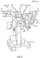
- FIG. 3is a perspective view of a surgical robotic arm for use as a patient side manipulator or endoscopic camera manipulator.
- FIGS. 5A-5Bare a side view and a cross-section view of a portion of the surgical robotic arm shown in FIG. 3 illustrated as mounting to a set-up joint of the robotic patient-side system of FIG. 2 .
- FIGS. 6-9are perspective views illustrating the mounting and dismounting of the robotic surgical arm of FIG. 3 with a set-up arm of the robotic patient-side system of FIG. 2 .
- FIG. 11Ais a side cross-sectional view of the exemplary connector portion of the set-up joint portion of FIGS. 6-10 .
- FIG. 11Bis a magnified side cross-sectional view of the exemplary connector portion illustrated in FIG. 11A .
- FIG. 12is an exploded perspective view of alternate exemplary embodiment of the connector portion shown in FIGS. 6-11B
- FIG. 13Ais an exploded perspective view of alternate exemplary embodiment of the connector portion shown in FIG. 12 .
- FIG. 14Bis an exploded perspective view of a yet another exemplary embodiment of the invention.
- FIG. 17is a bottom view of an alternate connecting section of the surgical robotic arm to couple to the connector portion of the set up joint portion shown in FIG. 14 .
- a robotic surgical systemincluding one or more robotic surgical arms with electro-mechanical interfaces to mount and dismount with electro-mechanical interfaces of set up arms of a patient side system.
- At least one of the robotic manipulator armsis used to support a stereo or three dimensional surgical image capture device 110 such as a stereo endoscope (which may be any of a variety of structures such as a stereo laparoscope, arthroscope, hysteroscope, or the like), or, optionally, some other stereo imaging modality (such as ultrasound, fluoroscopy, magnetic resonance imaging, or the like).
- a stereo endoscopewhich may be any of a variety of structures such as a stereo laparoscope, arthroscope, hysteroscope, or the like
- some other stereo imaging modalitysuch as ultrasound, fluoroscopy, magnetic resonance imaging, or the like.
- Robotic surgerymay be used to perform a wide variety of surgical procedures, including but not limited to open surgery, neurosurgical procedures (such as stereotaxy), endoscopic procedures (such as laparoscopy, arthroscopy, thoracoscopy), and the like.
- a user or operator O(generally a surgeon) performs a minimally invasive surgical procedure on patient P by manipulating control input devices 160 at a master control console 150 .
- a computer 151 of the console 150directs movement of robotically controlled endoscopic surgical instruments 101 A- 101 C by means of one or more control cables 159 , effecting movement of the instruments using a robotic patient-side system 152 (also referred to as a patient-side cart).
- the robotic patient-side system 152has one or more robotic arms 158 .
- the one or more robotic arms 158have a strap drive system.
- the robotic patient-side system 152includes at least three robotic manipulator arms 158 A- 158 C supported by linkages 156 , 156 ′, with a central robotic arm 158 B supporting an endoscopic camera 101 B and the robotic arms 158 A, 158 C to left and right of center supporting tissue manipulation tools 101 A and 101 C.
- the robotic patient-side system 152includes a positioning portion and a driven portion.
- the positioning portion of the robotic patient-side system 152remains in a fixed configuration during surgery while manipulating tissue.
- the driven portion of the robotic patient-side system 152is actively articulated under the direction of the operator O generating control signals at the surgeon's console 150 during surgery.
- the actively driven portion of the robotic patient-side system 152is generally referred to herein as the robotic arms or alternatively to robotic surgical manipulators.
- the positioning portion of the robotic patient-side system 152 that is in a fixed configuration during surgerymay be referred to as “set up arms” 156 , 156 ′ with positioning linkage and/or “set-up joints” (SUJ).
- the robotic patient-side system 152may be replaced by set up arms that couple at one end to left and right sides of the operating table T.
- the three robotic manipulator arms 158 A- 158 Cmay then be coupled to the opposite end of the set-up arms to ground to the table T.
- manipulatorssuch as robotic surgical arms 158 A and 158 C actuating the tissue affecting surgical tools 101 A and 101 C are generally referred to herein as a PSM (patient-side manipulators), and a robotic surgical arm 158 B controlling an image capture or data acquisition device, such as the endoscopic camera 101 B, is generally referred to herein as a ECM (endoscope-camera manipulator), it being noted that such telesurgical robotic manipulators may optionally actuate, maneuver and control a wide variety of instruments, tools and devices useful in surgery.
- the surgical tools 101 A, 101 C and endoscopic camera 101 Bmay be generally referred to herein as tools or instruments 101 .
- An assistant Amay assist in pre-positioning of the robotic patient-side system 152 relative to patient P as well as swapping tools or instruments 101 for alternative tool structures, and the like, while viewing the internal surgical site via an assistant's display 154 .
- the assistant Amay also swap in and out the robotic surgical arms 158 A and 158 C, as well as the robotic surgical arm 158 B, in case one is defective or failing.
- a robotic surgical armmay be swapped out for maintenance, adjustments, or cleaning and then swapped back in by one or more service persons.
- the robotic patient-side system 152may have one or more robotic surgical arms (a.k.a., robotic surgical manipulators) 158 A- 158 C with a strap drive system.
- the robotic arms 158 A, 158 Care for coupling to robotic surgical tools 101 A, 101 C.
- the robotic arm 158 Bis for coupling to an endoscopic camera 101 B.
- the surgical robotic arms 158 A- 158 Cmay be referred to as a surgical robotic arm or a robotic surgical arm 158 .
- the robotic patient-side system 152further includes a base 202 from which the robotic surgical instruments 101 may be supported. More specifically, the robotic surgical instruments 101 are each supported by the positioning linkage 156 and the surgical robotic arms 158 .
- the linkage structuresmay optionally be covered by protective covers or not to minimize the inertia that is manipulated by the servomechanism and the overall weight of robotic patient-side system 152 .
- the robotic patient-side system 152generally has dimensions suitable for transporting between operating rooms. It typically can fit through standard operating room doors and onto standard hospital elevators.
- the robotic patient-side system 152may have a weight and a wheel (or other transportation) system that allows the cart to be positioned adjacent to an operating table by a single attendant.
- the robotic patient-side system 152may be sufficiently stable during transport to avoid tipping and to easily withstand overturning moments that may be imposed at the ends of the robotic arms during use.
- the robotic surgical arms 158are for coupling to robotic surgical tools 101 .
- the robotic surgical arms 158each include serial links 341 - 344 pivotally coupled in series at joints 312 - 314 near respective ends of the links.
- the first link (Link 1 ) 341is pivotally coupled to a drive mount 340 at a first joint 311 near a first end and the second link (Link 2 ) 342 at the second joint 312 near a second end.
- the third link (Link 3 ) 343is pivotally coupled to the second link 342 near a first end and pivotally coupled to the fourth link (Link 4 ) 344 near a second end.
- the fourth linkis substantially in parallel to the insertion axis 374 of the robotic surgical tool.
- a fifth link (Link 5 ) 345is slidingly coupled to the fourth link 344 .
- a sixth link (Link 6 ) 346is slidingly coupled to the fifth link 345 .
- Various types of surgical tools 428couple to the sixth link 346 .
- the robotic surgical arms 158include the mounting base or drive mount 340 that allows them to be mounted and supported by set-up arms/joints 156 and 156 ′ of a cart mount, ceiling mount, floor/pedestal mount, or other mounting surface of a patient side system 152 .
- the mounting base or drive mount 340is pivotally coupled to the first link 341 to yaw the links of the robotic surgical arm about a yaw axis.
- the third link 343has a bend with respect to the pitch axis that is offset from center.
- the bend in the third linkallows the links 342 - 344 to be brought more closely together and provide a greater range of pitch in the robotic arm.
- the bendmay be formed at different angles depending upon the lengths and shapes of the other links. With the bend, the third link is shaped somewhat like a hockey stick.
- the first link 341also has a bend with respect to the pitch axis.
- the third link 343may alternately be referred to as a bent link, the main bent link, or a hockey stick shaped link.
- the second link 342provides a vertical motion in the third link 343 .
- the second link 342may house the motor to drive the linkage of the arm.
- the second link 342may also be referred to as the vertical link or the drive link.
- the fourth link 344typically slidingly holds the robotic surgical tool or the endoscopic camera through the fifth and sixth links
- the fourth linkmay also be referred to as the instrument holder link.
- FIG. 4a schematic diagram of a strap drive train as an exemplary embodiment of a robotic surgical arm 400 is illustrated.
- the strap drive train of the robotic surgical arm 400may be used in the structure of the arms 158 A- 158 C illustrated in FIGS. 1 , 2 , and 3 in one embodiment of the invention.
- the strap drive train of the robotic surgical arm 400drives the weight or load of the robotic arm itself from the links, joints, pulleys, cables, straps, etc. and the load that may be placed on it by the surgical tool in the surgical site. Without the strap drive train, the robotic surgical arm 400 would collapse and a remote center point 466 would not be maintained.
- drive train meansmay be used in the structure of the robotic surgical arms 158 A- 158 C illustrated in FIGS. 1 , 2 , and 3 , such as a continuous toothed timing belt with a timing gear, mechanical cables (one or more in parallel together) with shouldered pulleys, chains with sprockets, continuous perforated metal tapes around pulleys with bull nose pins, as well as other like drive train.
- the strap drive train of the robotic surgical arm 400includes six pulleys 404 , 408 A, 408 B, 410 , 412 A, 412 B and four straps 424 A, 424 B, 426 A, 426 B in one embodiment of the invention.
- the six pulleys 404 , 408 A, 408 B, 410 , 412 A, 412 B and four straps 424 A, 424 B, 426 A, 426 Bare configured with the links and joints of the robotic surgical arm 400 to constrain the motion of the shaft 430 of the surgical tool or endoscopic camera relative to the center of rotation 466 .
- straps 424 A- 624 Bare coupled between pulleys 404 and 408 A.
- the straps 426 A- 626 Bare coupled between pulleys 408 B, 610 and ride over the idler pulleys 412 A, 612 B, respectively, in one embodiment of the invention.
- pulley 404is rigidly coupled to the first link 341 .
- pulley 408 Ais rigidly coupled to the third link 343 .
- pulley 408 Bis rigidly coupled to the second link 342 .
- pulley 410is rigidly coupled to the fourth link 344 .
- pulley 404 , 408 A, 408 B, 410 , 412 A, 412 B, 412 ′can include wheels, gears, sprockets, pulleys with bullnose pins, and the like.
- two straps 426 A, 426 Bare shown being used in the third link 343 between pulleys 410 and 408 B, three straps may be used in another embodiment of the invention. In this case, strap 426 A is used between pulleys 410 and 408 B, a second strap is used between pulley 408 B and a pulley 412 (pulley 412 A, 412 B coupled together), and a third strap is used between pulley 412 and pulley 410 .
- the mounting base or drive mount 340includes a motor 401 to yaw the robotic arm 400 about the axis 456 illustrated in FIG. 4 .
- the mounting base or drive mount 340 of the surgical robotic arm 400includes electrical and mechanical connectors 452 to mate with electrical and mechanical connectors 450 in a connector portion of a set-up joint of the set up arm 156 , 156 ′.
- fasteners 462(such as bolts) may be used to rigidly couple the robotic surgical arm 400 to the set up arm 156 , 156 ′.
- a lever armmay be used to lock and unlock the arm 400 from the arms 156 , 156 ′ to quickly mount and dismount the robotic surgical arm from the patient side system.
- Including a slideable electro-mechanical interface between the surgical robotic arm 400 and the set up arm 156 , 156 ′can also assist in quickly mounting and dismounting a robotic surgical arm from a patient side system.
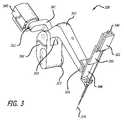
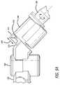
- FIGS. 5A-5Ba side view and a sectional view of a surgical robotic arm (SRA) portion 540 of a surgical robotic arm 158 and a set-up joint (SUJ) portion 556 of a set up arm 156 , 156 ′ of the robotic patient-side system 152 is shown.
- the SRA portion 540 of the surgical robotic arm 158is mechanically and electrically coupled coincidentally to the SUJ portion 556 of the set up arm 156 as shown in FIG. 5A . That is, the SRA portion 540 and the SUJ portion 556 mechanically and electrically couple together substantially simultaneously to form a joint.
- the SRA portion 540is adapted for mechanically coupling to the SUJ portion 556 of the set up arm.
- a connector section 541 of the SRA portion 540can be slid into and out of a connector portion 570 of the SUJ portion 556 as illustrated by double headed arrow 544 in FIG. 5A .
- the connector section 541 of the SRA portion 540has a slot 542 for receiving a tab 572 of the SUJ portion 556 .
- the SUJ portion 556may also be referred to herein simply as a set-up joint 556 .
- the SRA portion 540may also be referred to herein previously as a drive mount 340 or a mounting base 340 .
- the connector section 541 of the SRA portion 540is adapted for electrically coupling to the connector portion 570 of SUJ portion 556 .
- the connector portion 570 of SUJ portion 556includes one or more electrical connectors 560 , such as electrical connectors 650 A and 650 B in FIG. 6 or an electrical connector 1450 in FIG. 14 , as described in greater detail in conjunction with FIGS. 6 and 14 below.
- the connector section 541 of the SRA portion 540respectively includes one or more electrical connectors 550 , such as electrical connectors 750 A and 750 B shown in FIG. 7 or a single wide electrical connector 1750 shown in FIG. 17 , as described in greater detail in conjunction with FIGS. 7 and 17 below.
- the electrical connectors 550 and 560are first aligned together and then electrically and mechanically coupled together.
- the electrical connectors 550 in the SRA portion 540are fixed in position and the electrical connectors 560 in the SUJ portion 556 are adjustable in position such that they can be aligned to the connectors 550 .
- the electrical connectors 560 in the SUJ portion 556are fixed in position and the electrical connectors 550 in the SRA portion 540 are adjustable in position such that they can be aligned to the connectors 560 .
- One or more bolts 590 , 462 , or 900are used to remove any play between the connector section 541 of the SRA portion 540 and the connector portion 570 of SUJ portion 556 by forcing surface to surface contact between each.
- one or more cables 551are used to couple data signals, control signals, power, and ground from the connectors 550 to the electrical system of the surgical robotic arm 158 .
- one or more cables 561are used to couple data signals, control signals, power, and ground from the connectors 560 to the electrical system of the patient side system 152 .
- FIGS. 6-9detailed perspective views of the SRA portion 540 of the robotic surgical arm 158 and the SUJ portion 556 of the set up arm 156 are illustrated to better show how they slide apart and together.
- the connector section of the SRA portion 540is adapted to connect to the connector portion 570 of the SUJ portion 556 .
- FIGS. 6-9magnified views are provided that do not show the entire surgical robotic arm 158 or the entire set-up arm 156 .
- FIGS. 8-9portions of the surgical robotic arm 158 have been removed (e.g., disassembled) to better illustrate the connector section thereof and the connector portion of the set-up joint.
- electrical connectors 650 A and 650 Bare D-subminiature (D-SUB) electrical connectors, although any connector with a flange mount can also be used.
- D-sub electrical connectorhas two or more parallel rows of pins or sockets surrounded by a D-shaped metal shield.
- the D-shaped metal shieldprovides screening against electromagnetic interference and assures correct orientation.
- the D-shaped metal shieldmay be coupled to the overall screen of the cable if used, creating an electrically continuous screen covering the whole cable and connector system.
- a male D-sub electrical connectorhas pin contacts.
- a female D-sub electrical connectorhas socket contacts.
- the D-shaped shield of the female D-sub electrical connectorfits tightly inside the D-shaped shield of the male D-sub electrical connector.
- D-sub electrical connectorsare further described in international standard DIN 41652 by the German Institute for Standardization.
- Electrical connectors 650 A and 650 Binclude pins for carrying control and data signals, power and ground. Electrical connector 650 B provides shielding for its signal pins from electromagnetic interferences, such as those from the electrical connector 650 A that may provide power and ground to electric motors. Chassis ground may be made through the mechanical interface (e.g., flanges, tabs, rails, and bolts) or additional ground strapping. As described in greater detail below, the electrical connectors 650 A and 650 B may be referred to as “floating” electrical connectors.
- the mounting bracket 655supports the electrical connectors 650 A and 650 B along the Z-axis 544 so there is little movement in the Z-axis direction in order to mate with electrical connectors in the surgical robotic arm 158 .
- the Z-axis 544is parallel to the axis of the pins/sockets of the electrical connectors 650 A- 650 B while the X-axis and the Y-axis are perpendicular to the axis of the pins/sockets of the electrical connectors 650 A- 650 B.
- the SRA portion 540includes a pair of electrical connectors 750 A and 750 B to mate respectively with the electrical connectors 650 A and 650 B of the set up joint 556 .
- the SRA portion 540further includes a housing 770 that forms a pair of left and right flanges 762 and a pair of left and right guide slots 761 at the connector section end 541 .
- the flanges 762 on each sideinitially engage a top portion the mounting rails 660 and slide along the mounting rails 660 of the SUJ portion 556 .
- the guide slots 761then slide along over the guide tabs 662 of the SUJ portion 556 and finally mate or catch behind the flanges 762 of the SRA portions 540 .
- the final mating of the guide tabs 662 with the flanges 762reduces the pivoting of the SRA portion 540 away from the SUJ portion 556 .
- the SRA portion 540further includes a mounting bracket 758 bolted to the housing 770 by a plurality of bolts.
- the mounting bracket 758supports the electrical connectors 750 A and 750 B in a fixed position (X-axis, Y-axis, Z-axis) with respect to the SRA portion 540 in one embodiment of the invention. That is, with the electrical connectors 650 A- 650 B being able to float, the electrical connectors 750 A and 750 B can be held in a fixed position.
- floating electrical connectors 650 A and 650 B in the SUJ portion 556are respectively aligned with its pins and mate with the sockets of the electrical connectors 750 A and 750 B in the SRA portion 540 coincidentally with the final mating of the guide tabs 662 with the flanges 762 of the housing 770 .
- the mounting bracketbolted to the housing 770 , it can be readily detached to allow worn parts to be replaced.
- the mounting bracket 655includes a left side 655 L, a right side 655 R, and a base 655 B.
- the left mounting rail 660is formed in the left side 655 L with the left guide tab 662 .
- the right mounting rail 660is formed in the right side 655 R with the right guide tab 662 .
- the base 655 B of the mounting bracket 655includes the openings 1008 A- 1008 B.
- SRA portion 540includes a plurality of holes 910 , such as four holes 910 , for receiving of a plurality of fasteners 900 , such as four fasteners 900 , such as bolts, to rigidly couple the SRA portion 540 to the rest of the surgical arms 158 A and 158 C.
- the SUJ portion 556remains fixed, while the SRA portion 540 is lifted onto the SUJ portion 556 .
- the opposing guide flanges 762 of the SRA portion 540slide into the mounting rails 660 of the SUJ portion 556 .
- electrical connectors 1401 A and 1401 Balso float independently but require some extra space between the connectors.
- the electrical connectors 1401 A and 1401 Bare allowed to move by means of floating bushings 1410 .
- a single electrical connector 1450is a floating electrical connector, which is allowed to move by means of floating bushings 1410 .
- electrical connectors 650 A′- 650 B′ and 650 A- 650 Bfloat together coupled to a floating bracket 1200 , which is allowed to move by means of short shoulder screws 1252 ( FIG. 12 ) or two “floating” bushings 1310 ( FIGS. 13A-13B ).
- the short shoulder screws 1252 and floating bushings 1310allow a very small amount of motion in the axial direction but sufficient motion in the perpendicular plane to account for positional mismatch of the electrical connectors 650 A′- 650 B′ and 650 A- 650 B with their mating electrical connectors 750 A- 750 B.
- Connectors 650 A and 650 Bcan move in directions perpendicular to the Z-axis 1090 , such as in the direction shown by arrows 1091 X, 1091 Y and 1090 X, 1090 Y, respectively, which respectively correspond to the X and Y axes in the Cartesian coordinate system.
- the capture plate 1004is coupled to the mounting bracket 655 by way of a pair of screws 1001 .
- the pair of screws 1001is inserted into a pair of holes 1002 in the capture plate 1004 that allow the threaded shaft of the screws to pass but not the screw heads.
- the threaded shaft of the screws 1001are then screwed into a pair of threaded screw holes 1003 in the base of the mounting bracket 655 to secure the capture plate 1004 thereto.
- the mounting bracket 655further includes a plurality of openings 1032 in a mounting flange 1030 .
- the plurality of openings 1032 in a mounting flange 1030allow the passage of a cylindrical portion of a plurality of threaded bolts 1035 , but for the head of the bolts.
- One pair of openingsare spaced apart in the mounting bracket 655 and located near a top edge of a mounting flange 1030 and a second pair of spaced apart openings 1032 are located near a bottom edge of the mounting flange 1030 .
- the housing 670includes a plurality of threaded bolt holes 1235 to receive the plurality of threaded bolts 1035 so that the mounting bracket 655 may be tightly coupled to the housing 670 .
- the mounting bracket 655further includes a pair of openings 1033 in the mounting flange 1030 to allow the passage of a cylindrical portion of the plurality of threaded bolts 900 , but for the head of the bolts. That is, the pair of openings 1033 in the mounting flange 1030 align with a pair of the openings 910 in the SRA portion 540 .
- the housing 670includes a plurality of threaded bolt holes 1235 to receive the plurality of threaded bolts 900 so that the SRA portion 540 of the surgical robotic arm may be tightly coupled to the connector portion 570 of the set-up joint 556 .
- guide pins 1100 inserted into guide pin holes 1000 of the mounting bracket 655control the range of movement of each of the electrical connectors 650 A and 650 B.
- two of the four guide pins 1100are couple into a pair of connector openings or holes 1010 in each of the electrical connectors 650 A and 650 B to align each of the electrical connectors 650 A and 650 B with the fixed connectors 750 A and 750 B (shown in FIG. 15 ), respectively, in the SRA portion 540 .
- a pair of the guide pin holes 1000may overlap into the openings 1008 A- 1008 B for the electrical connectors.
- the use of independently floating electrical connectors 650 A and 650 B in the SUJ portion 556makes it easier for the fixed connectors 750 A and 750 B in the SRA portion 540 to electrically align with the floating electrical connectors 650 A and 650 B.
- FIG. 11Aa side sectional view of the connector portion 570 taken along the line A-A (through the alignment pin) in FIG. 10 is shown.
- FIG. 11Bis a magnified side sectional view of the electrical connector mounted in a sliding pocket.
- the guide pin 1100allows for a floating movement of the electrical connectors 650 A and 650 B such as a positive float 1101 and a negative float 1102 .
- the positive float 1101 and the negative float 1102 in one directionis plus or minus 0.015 inches, for a total of 0.03 inches.
- the amount of connector float from its nominal/centered positionis at least as large as the maximum mechanical misalignment of the mating connectors due to all mechanical tolerances (distance B).
- the misalignment tolerated at which the tapered pin 1100 can still engage the connector hole 1010is at least as large as the sum of distance A and distance B.
- the size and shape of the sliding pockets 1080 A- 1080 Bare designed to constrain a flange 1105 of an electrical connector, such as electrical connectors 650 A and 650 B, in a plane, keeping it parallel to the capture flange 1104 of the capture plate 1004 and allow them to align with the fixed connectors 750 A and 750 B (shown in FIG. 15 ), respectively.
- the size and shape of the sliding pockets 1080 A- 1080 Bare also designed to allow the connectors 650 A- 650 B to translate with two degrees of freedom (“floating” in a plane) so that they can be guided and aligned with the fixed connectors 750 A- 750 B using the tapered guide pins 1100 .
- the sliding pockets 1080 A- 1080 B for the connectors 650 A- 650 Bare respectively formed by the openings 1008 A- 1008 B in the mounting bracket and the U shaped openings 1020 A- 1020 B.
- a pair of guide holes 1000may merge into the openings 1008 A- 1008 B and be considered as part of the sliding pockets 1080 A- 1080 B.
- the connector flanges 1105are captured in the sliding pockets 1080 A- 1080 B between a bottom surface of the bottom side 655 B of the bracket 655 (see FIG. 8 ) and a top recessed locating surface 1082 of the capture plate 1004 .
- the connectors 650 A- 650 Bare allowed to translate with two degrees of freedom within the top recessed locating surface 1082 of the capture plate 1004 .
- modified electrical connectors 650 A′ and 650 B′are rigidly attached to a common floating bracket 1200 via a first plurality of fasteners 1251 that may be screwed into threaded holes 1253 on the flanges of the electrical connectors.
- the modified electrical connectors 650 A′ and 650 B′if female connectors, have shielding that is slightly flared outward, referred to as flared shielding, to mate with male connectors that are modified having shielding that is slightly tapered inward, referred to as tapered shielding.
- the modified electrical connectors 650 A′ and 650 B′are male connectors, they have tapered shielding that is slightly tapered inward to mate with female connectors that are modified having flared shielding that is slightly flared outward.
- the connectors 650 A′- 650 B′by design, will tolerate some small amount of misalignment.
- no guide pin from the connector section 541 of the SRA portion 540is used to align the electrical connectors or the common floating bracket of the connector portion 570 of the SUJ.
- a second plurality of fastenerssuch as short shoulder screws 1252 as illustrated or screws 1356 inserted through floating bushings 1310 in the floating bracket 1200 (shown in FIG. 13 A)—hold the floating bracket 1200 to the mounting bracket 655 ′ in the Z direction while allowing the floating bracket to move a small amount in the X and Y directions.
- Fasteners 1252 or 1356extend through the openings 1254 in the floating bracket 1200 and are screwed into threaded holes 1255 in the left and rights sides of the mounting bracket 655 ′.
- the mounting bracket 655 ′is modified slightly from the mounting bracket 655 (see FIG. 8 ).
- the mounting bracket 655 ′includes the left side 655 L and the right side 655 R but does not have the base portion 655 B. Instead, at the bottom of the left side 655 L and the right side 655 R, are the threaded holes 1255 in the mounting bracket 655 ′.
- FIGS. 13A-13Ban exploded perspective view of an alternate embodiment of the connector portion 570 of FIG. 12 is shown.
- guide pins of the connector section 541 of the SRA portion 540are used to align the common floating bracket 1200 and the electrical connectors 650 A- 650 B coupled thereto.
- the mounting bracket 655 ′ and the floating bracket 1200are similar to those of the fourth embodiment of the invention illustrated in FIG. 12 .
- standard electrical connectors 650 A- 650 Bmay be used instead of the modified connectors 650 A′- 650 B′ having the tapered/flared shielding.
- the way the electrical connectors 650 A- 650 B are coupled to the floating bracket 1200is different.
- a plurality of grommets 1324rigidly couple the electrical connectors 650 A- 650 B to the common floating bracket 1200 .
- the plurality of grommets 1324align and couple holes 1256 in the common floating bracket 1200 to through holes 1357 in the connector flanges of the connectors 650 A- 650 B.
- Fasteners 1252 or 1356extend through the openings 1254 in the floating bracket 1200 and are screwed into threaded holes 1255 in the left and rights sides of the mounting bracket 655 ′.
- two tapered guide pins 1100engage the outer most grommet holes in the outermost grommets 1324 to move the floating bracket 1200 and the electrical connectors 650 A and 650 B into correct alignment with the mating connectors 750 A and 750 B of the SRA.
- the fourth embodiment of the invention illustrated by FIG. 12Bdoes not require taper guide pins 1100 .
- the electrical connectors 650 A- 650 B, 650 A′- 650 B′respectively move together as they are both coupled to the floating bracket 1200 .
- FIG. 13Bis an exploded perspective view of the common floating bracket 1200 .
- the top common floating bracket 1200includes openings 1254 to receive floating bushings 1310 and fasteners 1356 to couple it to the mounting bracket 655 ′.
- Each of the holes 1256 in the bracket 1200receives a small metal grommet 1324 to rigidly fasten the flanges of connectors 650 A- 650 B to the floating bracket 1200 in the fifth embodiment of the invention.
- each of the holes 1256received a fastener 1251 in the fourth embodiment of the invention to rigidly fasten the flanges of connectors 650 A′- 650 B′ to the floating bracket 1200 .
- Openings in the outer pair of the grommets 1324are engaged by the alignment posts 1303 or guide pins 1100 in the SRA to move the floating bracket 1200 and the electrical connectors into correct alignment.
- the electrical connectors 650 A and 650 Bare floating connectors but float together in common with the bracket 1200 , rather then independently as in the embodiment shown in FIG. 10 .
- the bracket 1200floats such as shown in the direction of arrows 1390 X and 1390 Y, respectively, which respectively correspond to the X and Y axes in the Cartesian coordinate system.
- Connectors 1401 A and 1401 Beach contain two floating bushings 1410 and two guide pin holes 1411 . These connectors float independently from one another as does the connectors 650 A- 650 B in the preferred embodiment of invention illustrated in FIG. 10 .
- the electrical connectors 1401 A- 1401 Bmay also be referred to as floating electrical connectors.
- two floating bushings 1410are required on each connector to moveably couple them to the mounting bracket 655 ′′, an extra space between the connectors 1401 A- 1401 B is required. In one embodiment of the invention, the extra space is approximately 0.5 inches.
- a plurality of fasteners 1419are inserted through the opening in the floating bushings 1410 to moveably couple the electrical connectors 1401 A- 1401 B to the bracket 655 ′′.
- the mounting bracket 655 ′′is similar to the mounting bracket 655 but may include threaded holes 1403 to receive the inner fasteners 1419 .
- the outer fasteners 1419threadingly couple into the threaded holes 1003 .
- Guide pins or posts 1100 , 1303 from the SRAslide into the guide pin holes 1411 in each electrical connector 1401 A- 1401 B.
- the guide pins or posts inserted into the guide pin holesalign the electrical connectors 1401 A- 1401 B independently.
- the guide pins or postscause each electrical connector 1401 A- 1401 B to move about its floating bushings 1410 to align with the electrical connectors in the SRA.
- FIG. 14Bthe third embodiment of the invention, an exploded perspective view of an alternate embodiment of the connector portion 570 of the SUJ portion 556 is shown.
- a single floating electrical connector 1450is secured to the mounting bracket 1455 via floating bushings 1410 .
- the mounting bracket 1455is substantially similar to the bracket 655 ′ and lacks the base 655 B of the mounting bracket 655 .
- the electrical connector 1450is a floating electrical connector, which can move in the direction shown by arrows 1490 X and 1490 Y, which respectively correspond to the X and Y axes in the Cartesian coordinate system.
- the guide pins 1100 or alignment pins 1303 of a fixed connector, such as fixed connector 1750 illustrated in FIG. 17engage alignment or connector holes 1411 in the flange of the floating electrical connector 1450 .
- the floating electrical connector 1450then moves about its floating bushings 1410 to align with the electrical connector in the SRA.
- FIG. 14Ca side cross-sectional view of the floating electrical connectors of FIGS. 14A-14B is illustrated with the connector portion of the set up joint aligned to mate with the fixed connector of the robotic surgical arm.
- FIG. 14Cparticularly illustrates a cross section view of an exemplary floating bushing 1410 for use with the floating electrical connector, such as electrical connector 1401 A- 1401 B, 1450 illustrated in FIGS. 14A-14B .
- the floating bushings 1410are placed in float bushing openings 1420 of the flanges of the electrical connectors.
- a fastener 1419is inserted up through the opening in each of the floating bushings 1410 to thread into holes 1003 , 1403 .
- the floating bushing 1410is of a metallic composition, such as steel.
- Guide pin or post 1303 , 1100 of a fixed electrical connectorengages an alignment or connector hole 1411 (see FIGS. 14A-14B ) on the flange of the floating electrical connector 650 A.
- male conductive pins 1460may engage female conductive pins 1462 in the connectors or vise versa.
- connector sections 1500 and 1600 of the SRA portion 540 and 540 Bare illustrated respectively.
- the connector sections 1500 and 1600are substantially similar but for the alignment means used to align the floating electrical connectors 650 A and 650 B in the connector portion 570 of the SUJ joint 556 .
- the connector section 1500includes a bracket 758 for supporting a pair of fixed electrical connectors 750 A and 750 B to be respectively aligned with the flexible or floating electrical connectors 650 A and 650 B of the connector portion 570 of the SUJ portion 556 .
- the connector section 1500further includes four guide pins 1100 as shown in FIG. 15 for insertion into four connector holes 1010 of the connector portion 570 to independently align each of the floating electrical connectors 650 A and 650 B in the set up joint 556 .
- the connector section 1600includes two outer guide pins 1100 or two alignment pins 1203 shown in FIG. 16 such as to interface to the fifth embodiment of the invention illustrated by FIGS. 13A-13B .
- the two alignment pins 1203are inserted into two outer guide holes 1000 and then alignment holes of the mounting bracket 1200 of the connector portion 570 to align both of the floating electrical connectors 650 A and 650 B together in the set up joint 556 .
- the two inner guide pins 1100are unnecessary as both floating electrical connectors 650 A and 650 B move dependently together as part of a common floating bracket 1200 .
- Each of the connector sections 1500 and 1600further includes opposing guide slots 761 with flanges 762 for receiving guide tabs 662 , and bolt holes 910 for receiving the threaded cylindrical shaft of the bolts 900 but for the heads.
- the guide tabs 662 of the SUJ portion 556mates with the flanges 762 of the SRA portions 540 , 540 B. With the guide tabs 662 fully mated with the flanges 762 , the bolts 900 can be used to rigidly couple the SRA portions 540 , 540 B to SUJ portion 556 . The mating of the guide tabs 662 with the flanges 762 reduces the pivoting of the SRA portion 540 , 540 B away from the SUJ portion 556 .
- the bolts 900inserted through the bolt holes 910 and screwed into the threaded openings 1236 in the SUJ portion, couple the SRA portion 540 , 540 B to the SUJ portion 556 to substantially eliminate any pivot
- the mounting bracket 758is coupled to the housing 770 by a plurality of bolts 1558 inserted through openings in the top portion of the bracket and threaded into a plurality of bolt holes 1560 .
- the guide pins 1100couple to the base of the mounting bracket 758 to point down towards alignment holes in the SUJ portion 556 .
- the electrical connectors 750 A and 750 Bare held in a fixed position being coupled to the bracket 758 by conventional means.
- the pins of the electrical connectors 750 A- 750 Bpoint down to mate with the sockets of the electrical connectors 650 A- 650 B which point up.
- the fixed connectors 750 A and 750 B of each SRA portion 540 , 540 Bare male D-SUB electrical connectors with male pins and the floating electrical connectors 650 A and 650 B in the connector portion 570 of the setup joint are female D-SUB electrical connector with female pins (“sockets”) to receive the male pins and make an electrical connection between each.
- the gender of the connectorsis swapped with the fixed connectors 750 A and 750 B being female D-SUB electrical connectors with female pins (“sockets”) and the floating electrical connectors 650 A and 650 B being male D-SUB electrical connectors with male pins.
- electrical connectors 650 A and 750 Aare 26 pin D-subminiature electrical connectors having a shell size 2 and electrical connectors 650 B and 750 B are 9 pin D-subminiature electrical connectors having a shell size 1.
- FIG. 17an alternate SRA portion 540 C of the robotic surgical arm is illustrated for coupling to the single floating electrical connector 1450 in the connector portion 570 of the setup joint of the third embodiment of the invention illustrated in FIG. 14B .
- the connector section 1700 of the SRA portion 540 Cincludes two outer alignment pins 1303 and a single fixed connector 1750 .
- the outer alignment pins 1303are used to move the single floating electrical connector 1450 (see FIG. 14 ) of the set up joint into alignment to be mated to the single fixed connector 1750 of the SRA portion 540 C of the robotic surgical arm.
- the single fixed connector 1750 of the SRA portion 540 Cis a male D-SUB electrical connector with male pins and the floating electrical connector 1450 in the connector portion 570 of the setup joint is a female male D-SUB electrical connector with female pins (“sockets”) to receive the male pins and make an electrical connection between each.
- the gender of the connectorsis swapped with the fixed connector 1750 being a female D-SUB electrical connector with female pins (“sockets”) and the floating electrical connector 1450 being a male D-SUB electrical connector with male pins.
- electrical connectors 1450 and 1750are 43 pin D-subminiature connectors having a shell size 5.
- the alternate SRA portion 540 Cincludes a slightly different mounting bracket 1758 over the mounting bracket 758 .
- the base of the mounting bracket 1758need only hold a single fixed connector 1750 in a fixed position in comparison with the mounting bracket 758 .
- the mounting bracket 1758may be similarly coupled to the housing 770 by a plurality of bolts 1558 coupled into threaded bolt holes 1560 .
- the mounting bracket 1758may be molded together and formed as part of the housing 770 .
- the SRA portion 540 C of the robotic surgical armis substantially similar to the SRA portion 540 including its elements described previously.
- the embodiments of the inventionallow for the electrical connections to occur passively as the mechanical connection is made.
- one half of each mating electrical connectorfloats independently of other electrical connectors in one embodiment of the invention.
- the floating of the electrical connectorsreduces misalignment due to the tolerance stack up of the mechanical guide rails and the connectors themselves.
- the embodiments of the inventionallow for the electrical connection on one side to float so that it will align correctly to the mating connector under the tight tolerances of the electrical connector without damage due to misalignment from the mechanical connection.
- floating the electrical connectorsallows multiple connectors to float independently while minimizing the space to do so.
- only a minimal number of partsare required to constrain any number of electrical connectors and allow them to float independently.
Landscapes
- Chemical & Material Sciences (AREA)
- Engineering & Computer Science (AREA)
- Health & Medical Sciences (AREA)
- Organic Chemistry (AREA)
- Life Sciences & Earth Sciences (AREA)
- Combustion & Propulsion (AREA)
- Surgery (AREA)
- General Health & Medical Sciences (AREA)
- Robotics (AREA)
- Chemical Kinetics & Catalysis (AREA)
- Oil, Petroleum & Natural Gas (AREA)
- Medical Informatics (AREA)
- Nuclear Medicine, Radiotherapy & Molecular Imaging (AREA)
- General Chemical & Material Sciences (AREA)
- Biomedical Technology (AREA)
- Heart & Thoracic Surgery (AREA)
- Zoology (AREA)
- Molecular Biology (AREA)
- Animal Behavior & Ethology (AREA)
- Wood Science & Technology (AREA)
- Public Health (AREA)
- Veterinary Medicine (AREA)
- Biotechnology (AREA)
- Microbiology (AREA)
- Thermal Sciences (AREA)
- Physics & Mathematics (AREA)
- Biochemistry (AREA)
- Bioinformatics & Cheminformatics (AREA)
- General Engineering & Computer Science (AREA)
- Genetics & Genomics (AREA)
- Mechanical Engineering (AREA)
- Inorganic Chemistry (AREA)
- Details Of Connecting Devices For Male And Female Coupling (AREA)
- Manipulator (AREA)
Abstract
Description
Claims (29)
Priority Applications (4)
| Application Number | Priority Date | Filing Date | Title |
|---|---|---|---|
| US11/466,097US7762825B2 (en) | 2005-12-20 | 2006-08-21 | Electro-mechanical interfaces to mount robotic surgical arms |
| PCT/US2006/062018WO2007120330A2 (en) | 2005-12-20 | 2006-12-13 | Electro-mechanical interfaces to mount robotic surgical arms |
| US12/793,871US8066524B2 (en) | 2005-12-20 | 2010-06-04 | Surgical system with electro-mechanical interfaces to mount robotic surgical arms |
| US13/281,321US8585420B2 (en) | 2005-12-20 | 2011-10-25 | Apparatus for surgical systems with electro-mechanical interfaces to mount robotic surgical arms |
Applications Claiming Priority (2)
| Application Number | Priority Date | Filing Date | Title |
|---|---|---|---|
| US75244605P | 2005-12-20 | 2005-12-20 | |
| US11/466,097US7762825B2 (en) | 2005-12-20 | 2006-08-21 | Electro-mechanical interfaces to mount robotic surgical arms |
Related Child Applications (2)
| Application Number | Title | Priority Date | Filing Date |
|---|---|---|---|
| US12/798,871DivisionUS8585789B2 (en) | 2010-04-13 | 2010-04-13 | Methods for gasification of carbonaceous materials |
| US12/793,871DivisionUS8066524B2 (en) | 2005-12-20 | 2010-06-04 | Surgical system with electro-mechanical interfaces to mount robotic surgical arms |
Publications (2)
| Publication Number | Publication Date |
|---|---|
| US20070142970A1 US20070142970A1 (en) | 2007-06-21 |
| US7762825B2true US7762825B2 (en) | 2010-07-27 |
Family
ID=38174769
Family Applications (3)
| Application Number | Title | Priority Date | Filing Date |
|---|---|---|---|
| US11/466,097Active2029-01-16US7762825B2 (en) | 2005-12-20 | 2006-08-21 | Electro-mechanical interfaces to mount robotic surgical arms |
| US12/793,871ActiveUS8066524B2 (en) | 2005-12-20 | 2010-06-04 | Surgical system with electro-mechanical interfaces to mount robotic surgical arms |
| US13/281,321Active2027-03-11US8585420B2 (en) | 2005-12-20 | 2011-10-25 | Apparatus for surgical systems with electro-mechanical interfaces to mount robotic surgical arms |
Family Applications After (2)
| Application Number | Title | Priority Date | Filing Date |
|---|---|---|---|
| US12/793,871ActiveUS8066524B2 (en) | 2005-12-20 | 2010-06-04 | Surgical system with electro-mechanical interfaces to mount robotic surgical arms |
| US13/281,321Active2027-03-11US8585420B2 (en) | 2005-12-20 | 2011-10-25 | Apparatus for surgical systems with electro-mechanical interfaces to mount robotic surgical arms |
Country Status (2)
| Country | Link |
|---|---|
| US (3) | US7762825B2 (en) |
| WO (1) | WO2007120330A2 (en) |
Cited By (237)
| Publication number | Priority date | Publication date | Assignee | Title |
|---|---|---|---|---|
| US20070142971A1 (en)* | 2005-12-20 | 2007-06-21 | Schena Bruce M | Hook and pivot electro-mechanical interface for robotic medical arms |
| US20090054909A1 (en)* | 2007-07-12 | 2009-02-26 | Board Of Regents Of The University Of Nebraska | Methods and systems of actuation in robotic devices |
| US20090326554A1 (en)* | 2008-06-30 | 2009-12-31 | Eigen, Inc. | Support assembly for a tracking assembly and mounted transrectal ultrasound probe |
| US20120124824A1 (en)* | 2005-12-20 | 2012-05-24 | Intuitive Surgical Operations, Inc. | Apparatus for surgical systems with electro-mechanical interfaces to mount robotic surgical arms |
| US20130012053A1 (en)* | 2010-03-02 | 2013-01-10 | Daniel Sirkett | System For Electrically Connecting A Tool To A Robot Wrist And A Method Therefor |
| US8679096B2 (en) | 2007-06-21 | 2014-03-25 | Board Of Regents Of The University Of Nebraska | Multifunctional operational component for robotic devices |
| US8834488B2 (en) | 2006-06-22 | 2014-09-16 | Board Of Regents Of The University Of Nebraska | Magnetically coupleable robotic surgical devices and related methods |
| US8894633B2 (en) | 2009-12-17 | 2014-11-25 | Board Of Regents Of The University Of Nebraska | Modular and cooperative medical devices and related systems and methods |
| US8968267B2 (en) | 2010-08-06 | 2015-03-03 | Board Of Regents Of The University Of Nebraska | Methods and systems for handling or delivering materials for natural orifice surgery |
| US8974440B2 (en) | 2007-08-15 | 2015-03-10 | Board Of Regents Of The University Of Nebraska | Modular and cooperative medical devices and related systems and methods |
| US9010214B2 (en) | 2012-06-22 | 2015-04-21 | Board Of Regents Of The University Of Nebraska | Local control robotic surgical devices and related methods |
| US9060781B2 (en) | 2011-06-10 | 2015-06-23 | Board Of Regents Of The University Of Nebraska | Methods, systems, and devices relating to surgical end effectors |
| US9078685B2 (en) | 2007-02-16 | 2015-07-14 | Globus Medical, Inc. | Method and system for performing invasive medical procedures using a surgical robot |
| US9089353B2 (en) | 2011-07-11 | 2015-07-28 | Board Of Regents Of The University Of Nebraska | Robotic surgical devices, systems, and related methods |
| USD756431S1 (en)* | 2015-05-19 | 2016-05-17 | F. Richard Langner | Robot accessory mount |
| US9403281B2 (en) | 2003-07-08 | 2016-08-02 | Board Of Regents Of The University Of Nebraska | Robotic devices with arms and related methods |
| US9498292B2 (en) | 2012-05-01 | 2016-11-22 | Board Of Regents Of The University Of Nebraska | Single site robotic device and related systems and methods |
| US9579088B2 (en) | 2007-02-20 | 2017-02-28 | Board Of Regents Of The University Of Nebraska | Methods, systems, and devices for surgical visualization and device manipulation |
| US9713499B2 (en) | 2011-12-05 | 2017-07-25 | Mazor Robotics Ltd. | Active bed mount for surgical robot |
| US9743987B2 (en) | 2013-03-14 | 2017-08-29 | Board Of Regents Of The University Of Nebraska | Methods, systems, and devices relating to robotic surgical devices, end effectors, and controllers |
| US9770305B2 (en) | 2012-08-08 | 2017-09-26 | Board Of Regents Of The University Of Nebraska | Robotic surgical devices, systems, and related methods |
| US9782229B2 (en) | 2007-02-16 | 2017-10-10 | Globus Medical, Inc. | Surgical robot platform |
| US9888966B2 (en) | 2013-03-14 | 2018-02-13 | Board Of Regents Of The University Of Nebraska | Methods, systems, and devices relating to force control surgical systems |
| US20180187757A1 (en)* | 2016-12-30 | 2018-07-05 | UBTECH Robotics Corp. | Waist rotation structure and robot |
| US10080615B2 (en) | 2015-08-12 | 2018-09-25 | Globus Medical, Inc. | Devices and methods for temporary mounting of parts to bone |
| US10117632B2 (en) | 2016-02-03 | 2018-11-06 | Globus Medical, Inc. | Portable medical imaging system with beam scanning collimator |
| US10136954B2 (en) | 2012-06-21 | 2018-11-27 | Globus Medical, Inc. | Surgical tool systems and method |
| US10160121B2 (en)* | 2017-05-17 | 2018-12-25 | Korea Institute Of Science And Technology | Module connection system |
| US10231791B2 (en) | 2012-06-21 | 2019-03-19 | Globus Medical, Inc. | Infrared signal based position recognition system for use with a robot-assisted surgery |
| US10292778B2 (en) | 2014-04-24 | 2019-05-21 | Globus Medical, Inc. | Surgical instrument holder for use with a robotic surgical system |
| US10335024B2 (en) | 2007-08-15 | 2019-07-02 | Board Of Regents Of The University Of Nebraska | Medical inflation, attachment and delivery devices and related methods |
| US10342561B2 (en) | 2014-09-12 | 2019-07-09 | Board Of Regents Of The University Of Nebraska | Quick-release end effectors and related systems and methods |
| US10357184B2 (en) | 2012-06-21 | 2019-07-23 | Globus Medical, Inc. | Surgical tool systems and method |
| US10376322B2 (en) | 2014-11-11 | 2019-08-13 | Board Of Regents Of The University Of Nebraska | Robotic device with compact joint design and related systems and methods |
| US10448910B2 (en) | 2016-02-03 | 2019-10-22 | Globus Medical, Inc. | Portable medical imaging system |
| US10566722B2 (en)* | 2018-07-18 | 2020-02-18 | Getac Technology Corporation | Float-type connecting module and float-type docking device having the module |
| US10573023B2 (en) | 2018-04-09 | 2020-02-25 | Globus Medical, Inc. | Predictive visualization of medical imaging scanner component movement |
| US10569794B2 (en) | 2015-10-13 | 2020-02-25 | Globus Medical, Inc. | Stabilizer wheel assembly and methods of use |
| US10580217B2 (en) | 2015-02-03 | 2020-03-03 | Globus Medical, Inc. | Surgeon head-mounted display apparatuses |
| US10582973B2 (en) | 2012-08-08 | 2020-03-10 | Virtual Incision Corporation | Robotic surgical devices, systems, and related methods |
| US10646283B2 (en) | 2018-02-19 | 2020-05-12 | Globus Medical Inc. | Augmented reality navigation systems for use with robotic surgical systems and methods of their use |
| US10660712B2 (en) | 2011-04-01 | 2020-05-26 | Globus Medical Inc. | Robotic system and method for spinal and other surgeries |
| US10667883B2 (en) | 2013-03-15 | 2020-06-02 | Virtual Incision Corporation | Robotic surgical devices, systems, and related methods |
| US10675094B2 (en) | 2017-07-21 | 2020-06-09 | Globus Medical Inc. | Robot surgical platform |
| US10702347B2 (en) | 2016-08-30 | 2020-07-07 | The Regents Of The University Of California | Robotic device with compact joint design and an additional degree of freedom and related systems and methods |
| US10722319B2 (en) | 2016-12-14 | 2020-07-28 | Virtual Incision Corporation | Releasable attachment device for coupling to medical devices and related systems and methods |
| US10751136B2 (en) | 2016-05-18 | 2020-08-25 | Virtual Incision Corporation | Robotic surgical devices, systems and related methods |
| US10806538B2 (en) | 2015-08-03 | 2020-10-20 | Virtual Incision Corporation | Robotic surgical devices, systems, and related methods |
| US10813704B2 (en) | 2013-10-04 | 2020-10-27 | Kb Medical, Sa | Apparatus and systems for precise guidance of surgical tools |
| US10842453B2 (en) | 2016-02-03 | 2020-11-24 | Globus Medical, Inc. | Portable medical imaging system |
| US10866119B2 (en) | 2016-03-14 | 2020-12-15 | Globus Medical, Inc. | Metal detector for detecting insertion of a surgical device into a hollow tube |
| US10893912B2 (en) | 2006-02-16 | 2021-01-19 | Globus Medical Inc. | Surgical tool systems and methods |
| US10898252B2 (en) | 2017-11-09 | 2021-01-26 | Globus Medical, Inc. | Surgical robotic systems for bending surgical rods, and related methods and devices |
| US10925681B2 (en) | 2015-07-31 | 2021-02-23 | Globus Medical Inc. | Robot arm and methods of use |
| US10939968B2 (en) | 2014-02-11 | 2021-03-09 | Globus Medical Inc. | Sterile handle for controlling a robotic surgical system from a sterile field |
| US10945742B2 (en) | 2014-07-14 | 2021-03-16 | Globus Medical Inc. | Anti-skid surgical instrument for use in preparing holes in bone tissue |
| US10966700B2 (en) | 2013-07-17 | 2021-04-06 | Virtual Incision Corporation | Robotic surgical devices, systems and related methods |
| US10973594B2 (en) | 2015-09-14 | 2021-04-13 | Globus Medical, Inc. | Surgical robotic systems and methods thereof |
| US11013564B2 (en) | 2018-01-05 | 2021-05-25 | Board Of Regents Of The University Of Nebraska | Single-arm robotic device with compact joint design and related systems and methods |
| US11045267B2 (en) | 2012-06-21 | 2021-06-29 | Globus Medical, Inc. | Surgical robotic automation with tracking markers |
| US11045179B2 (en) | 2019-05-20 | 2021-06-29 | Global Medical Inc | Robot-mounted retractor system |
| US11051894B2 (en) | 2017-09-27 | 2021-07-06 | Virtual Incision Corporation | Robotic surgical devices with tracking camera technology and related systems and methods |
| US11058378B2 (en) | 2016-02-03 | 2021-07-13 | Globus Medical, Inc. | Portable medical imaging system |
| US11109922B2 (en) | 2012-06-21 | 2021-09-07 | Globus Medical, Inc. | Surgical tool systems and method |
| US11116576B2 (en) | 2012-06-21 | 2021-09-14 | Globus Medical Inc. | Dynamic reference arrays and methods of use |
| US11134862B2 (en) | 2017-11-10 | 2021-10-05 | Globus Medical, Inc. | Methods of selecting surgical implants and related devices |
| US11153555B1 (en) | 2020-05-08 | 2021-10-19 | Globus Medical Inc. | Extended reality headset camera system for computer assisted navigation in surgery |
| US11173617B2 (en) | 2016-08-25 | 2021-11-16 | Board Of Regents Of The University Of Nebraska | Quick-release end effector tool interface |
| US11207150B2 (en) | 2020-02-19 | 2021-12-28 | Globus Medical, Inc. | Displaying a virtual model of a planned instrument attachment to ensure correct selection of physical instrument attachment |
| US11253216B2 (en) | 2020-04-28 | 2022-02-22 | Globus Medical Inc. | Fixtures for fluoroscopic imaging systems and related navigation systems and methods |
| US11253327B2 (en) | 2012-06-21 | 2022-02-22 | Globus Medical, Inc. | Systems and methods for automatically changing an end-effector on a surgical robot |
| US11266470B2 (en) | 2015-02-18 | 2022-03-08 | KB Medical SA | Systems and methods for performing minimally invasive spinal surgery with a robotic surgical system using a percutaneous technique |
| US11278360B2 (en) | 2018-11-16 | 2022-03-22 | Globus Medical, Inc. | End-effectors for surgical robotic systems having sealed optical components |
| US11284958B2 (en) | 2016-11-29 | 2022-03-29 | Virtual Incision Corporation | User controller with user presence detection and related systems and methods |
| US11298196B2 (en) | 2012-06-21 | 2022-04-12 | Globus Medical Inc. | Surgical robotic automation with tracking markers and controlled tool advancement |
| US11317973B2 (en) | 2020-06-09 | 2022-05-03 | Globus Medical, Inc. | Camera tracking bar for computer assisted navigation during surgery |
| US11317978B2 (en) | 2019-03-22 | 2022-05-03 | Globus Medical, Inc. | System for neuronavigation registration and robotic trajectory guidance, robotic surgery, and related methods and devices |
| US11317971B2 (en) | 2012-06-21 | 2022-05-03 | Globus Medical, Inc. | Systems and methods related to robotic guidance in surgery |
| US11337769B2 (en) | 2015-07-31 | 2022-05-24 | Globus Medical, Inc. | Robot arm and methods of use |
| US11337742B2 (en) | 2018-11-05 | 2022-05-24 | Globus Medical Inc | Compliant orthopedic driver |
| US11357548B2 (en) | 2017-11-09 | 2022-06-14 | Globus Medical, Inc. | Robotic rod benders and related mechanical and motor housings |
| US11357595B2 (en) | 2016-11-22 | 2022-06-14 | Board Of Regents Of The University Of Nebraska | Gross positioning device and related systems and methods |
| US11382713B2 (en) | 2020-06-16 | 2022-07-12 | Globus Medical, Inc. | Navigated surgical system with eye to XR headset display calibration |
| US11382549B2 (en) | 2019-03-22 | 2022-07-12 | Globus Medical, Inc. | System for neuronavigation registration and robotic trajectory guidance, and related methods and devices |
| US11382699B2 (en) | 2020-02-10 | 2022-07-12 | Globus Medical Inc. | Extended reality visualization of optical tool tracking volume for computer assisted navigation in surgery |
| US11382700B2 (en) | 2020-05-08 | 2022-07-12 | Globus Medical Inc. | Extended reality headset tool tracking and control |
| US11395706B2 (en) | 2012-06-21 | 2022-07-26 | Globus Medical Inc. | Surgical robot platform |
| US11399900B2 (en) | 2012-06-21 | 2022-08-02 | Globus Medical, Inc. | Robotic systems providing co-registration using natural fiducials and related methods |
| US11419616B2 (en) | 2019-03-22 | 2022-08-23 | Globus Medical, Inc. | System for neuronavigation registration and robotic trajectory guidance, robotic surgery, and related methods and devices |
| US11426178B2 (en) | 2019-09-27 | 2022-08-30 | Globus Medical Inc. | Systems and methods for navigating a pin guide driver |
| US11432890B2 (en) | 2018-01-04 | 2022-09-06 | Covidien Lp | Systems and assemblies for mounting a surgical accessory to robotic surgical systems, and providing access therethrough |
| US11432891B2 (en) | 2015-06-03 | 2022-09-06 | Covidien Lp | Offset instrument drive unit |
| USD963851S1 (en) | 2020-07-10 | 2022-09-13 | Covidien Lp | Port apparatus |
| US11439444B1 (en) | 2021-07-22 | 2022-09-13 | Globus Medical, Inc. | Screw tower and rod reduction tool |
| US11446099B2 (en) | 2016-06-03 | 2022-09-20 | Covidien Lp | Control arm for robotic surgical systems |
| US11464593B2 (en) | 2016-06-03 | 2022-10-11 | Covidien Lp | Passive axis system for robotic surgical systems |
| US11484372B2 (en) | 2019-02-15 | 2022-11-01 | Covidien Lp | Articulation mechanisms for surgical instruments such as for use in robotic surgical systems |
| US11510750B2 (en) | 2020-05-08 | 2022-11-29 | Globus Medical, Inc. | Leveraging two-dimensional digital imaging and communication in medicine imagery in three-dimensional extended reality applications |
| US11510684B2 (en) | 2019-10-14 | 2022-11-29 | Globus Medical, Inc. | Rotary motion passive end effector for surgical robots in orthopedic surgeries |
| US11510747B2 (en) | 2017-05-25 | 2022-11-29 | Covidien Lp | Robotic surgical systems and drapes for covering components of robotic surgical systems |
| US11517183B2 (en) | 2015-10-23 | 2022-12-06 | Covidien Lp | Surgical system for detecting gradual changes in perfusion |
| US11523509B2 (en) | 2016-05-26 | 2022-12-06 | Covidien Lp | Instrument drive units |
| US11523785B2 (en) | 2020-09-24 | 2022-12-13 | Globus Medical, Inc. | Increased cone beam computed tomography volume length without requiring stitching or longitudinal C-arm movement |
| US11529195B2 (en) | 2017-01-18 | 2022-12-20 | Globus Medical Inc. | Robotic navigation of robotic surgical systems |
| US11529203B2 (en) | 2015-09-25 | 2022-12-20 | Covidien Lp | Robotic surgical assemblies and instrument drive connectors thereof |
| US11547508B2 (en) | 2016-05-26 | 2023-01-10 | Covidien Lp | Robotic surgical assemblies |
| US11553984B2 (en) | 2016-06-03 | 2023-01-17 | Covidien Lp | Robotic surgical system with an embedded imager |
| US11553974B2 (en) | 2017-05-25 | 2023-01-17 | Covidien Lp | Systems and methods for detection of objects within a field of view of an image capture device |
| US11571171B2 (en) | 2019-09-24 | 2023-02-07 | Globus Medical, Inc. | Compound curve cable chain |
| US11571265B2 (en) | 2019-03-22 | 2023-02-07 | Globus Medical Inc. | System for neuronavigation registration and robotic trajectory guidance, robotic surgery, and related methods and devices |
| US11576739B2 (en) | 2018-07-03 | 2023-02-14 | Covidien Lp | Systems, methods, and computer-readable media for detecting image degradation during surgical procedures |
| US11576733B2 (en) | 2019-02-06 | 2023-02-14 | Covidien Lp | Robotic surgical assemblies including electrosurgical instruments having articulatable wrist assemblies |
| US11576562B2 (en) | 2016-04-07 | 2023-02-14 | Titan Medical Inc. | Camera positioning method and apparatus for capturing images during a medical procedure |
| US11586106B2 (en) | 2018-12-28 | 2023-02-21 | Titan Medical Inc. | Imaging apparatus having configurable stereoscopic perspective |
| US11583358B2 (en) | 2017-09-06 | 2023-02-21 | Covidien Lp | Boundary scaling of surgical robots |
| US11596489B2 (en) | 2015-03-10 | 2023-03-07 | Covidien Lp | Measuring health of a connector member of a robotic surgical system |
| US11602402B2 (en) | 2018-12-04 | 2023-03-14 | Globus Medical, Inc. | Drill guide fixtures, cranial insertion fixtures, and related methods and robotic systems |
| US11607149B2 (en) | 2012-06-21 | 2023-03-21 | Globus Medical Inc. | Surgical tool systems and method |
| US11612446B2 (en) | 2016-06-03 | 2023-03-28 | Covidien Lp | Systems, methods, and computer-readable program products for controlling a robotically delivered manipulator |
| US11615884B2 (en) | 2018-03-06 | 2023-03-28 | Digital Surgery Limited | Techniques for virtualized tool interaction |
| US11618171B2 (en) | 2013-12-11 | 2023-04-04 | Covidien Lp | Wrist and jaw assemblies for robotic surgical systems |
| US11622824B2 (en) | 2015-06-16 | 2023-04-11 | Covidien Lp | Robotic surgical system torque transduction sensing |
| US11628022B2 (en) | 2017-09-05 | 2023-04-18 | Covidien Lp | Collision handling algorithms for robotic surgical systems |
| US11628024B2 (en) | 2018-03-08 | 2023-04-18 | Covidien Lp | Surgical robotic systems |
| US11628023B2 (en) | 2019-07-10 | 2023-04-18 | Globus Medical, Inc. | Robotic navigational system for interbody implants |
| US11628039B2 (en) | 2006-02-16 | 2023-04-18 | Globus Medical Inc. | Surgical tool systems and methods |
| US11633243B2 (en) | 2018-10-10 | 2023-04-25 | Titan Medical Inc. | Instrument insertion system, method, and apparatus for performing medical procedures |
| US11647888B2 (en) | 2018-04-20 | 2023-05-16 | Covidien Lp | Compensation for observer movement in robotic surgical systems having stereoscopic displays |
| US11666395B2 (en) | 2015-06-23 | 2023-06-06 | Covidien Lp | Robotic surgical assemblies |
| US11690691B2 (en) | 2017-02-15 | 2023-07-04 | Covidien Lp | System and apparatus for crush prevention for medical robot applications |
| US11701186B2 (en) | 2013-12-15 | 2023-07-18 | Mazor Robotics Ltd. | Semi-rigid bone attachment robotic surgery system |
| US11717350B2 (en) | 2020-11-24 | 2023-08-08 | Globus Medical Inc. | Methods for robotic assistance and navigation in spinal surgery and related systems |
| US11717361B2 (en) | 2017-05-24 | 2023-08-08 | Covidien Lp | Electrosurgical robotic system having tool presence detection |
| US11717355B2 (en) | 2019-01-29 | 2023-08-08 | Covidien Lp | Drive mechanisms for surgical instruments such as for use in robotic surgical systems |
| US11737766B2 (en) | 2014-01-15 | 2023-08-29 | Globus Medical Inc. | Notched apparatus for guidance of an insertable instrument along an axis during spinal surgery |
| US11737831B2 (en) | 2020-09-02 | 2023-08-29 | Globus Medical Inc. | Surgical object tracking template generation for computer assisted navigation during surgical procedure |
| US11744655B2 (en) | 2018-12-04 | 2023-09-05 | Globus Medical, Inc. | Drill guide fixtures, cranial insertion fixtures, and related methods and robotic systems |
| US11779413B2 (en) | 2015-11-19 | 2023-10-10 | Covidien Lp | Optical force sensor for robotic surgical system |
| US11793588B2 (en) | 2020-07-23 | 2023-10-24 | Globus Medical, Inc. | Sterile draping of robotic arms |
| US11793570B2 (en) | 2012-06-21 | 2023-10-24 | Globus Medical Inc. | Surgical robotic automation with tracking markers |
| US11794338B2 (en) | 2017-11-09 | 2023-10-24 | Globus Medical Inc. | Robotic rod benders and related mechanical and motor housings |
| US11806084B2 (en) | 2019-03-22 | 2023-11-07 | Globus Medical, Inc. | System for neuronavigation registration and robotic trajectory guidance, and related methods and devices |
| US11813030B2 (en) | 2017-03-16 | 2023-11-14 | Globus Medical, Inc. | Robotic navigation of robotic surgical systems |
| US11819365B2 (en) | 2012-06-21 | 2023-11-21 | Globus Medical, Inc. | System and method for measuring depth of instrumentation |
| US11826114B2 (en) | 2017-11-29 | 2023-11-28 | Covidien Lp | Robotic surgical systems, instrument drive assemblies, and drive assemblies |
| US11839441B2 (en) | 2017-05-25 | 2023-12-12 | Covidien Lp | Robotic surgical system with automated guidance |
| US11850009B2 (en) | 2021-07-06 | 2023-12-26 | Globus Medical, Inc. | Ultrasonic robotic surgical navigation |
| US11857149B2 (en) | 2012-06-21 | 2024-01-02 | Globus Medical, Inc. | Surgical robotic systems with target trajectory deviation monitoring and related methods |
| US11857266B2 (en) | 2012-06-21 | 2024-01-02 | Globus Medical, Inc. | System for a surveillance marker in robotic-assisted surgery |
| US11864857B2 (en) | 2019-09-27 | 2024-01-09 | Globus Medical, Inc. | Surgical robot with passive end effector |
| US11864839B2 (en) | 2012-06-21 | 2024-01-09 | Globus Medical Inc. | Methods of adjusting a virtual implant and related surgical navigation systems |
| US11864745B2 (en) | 2012-06-21 | 2024-01-09 | Globus Medical, Inc. | Surgical robotic system with retractor |
| US11872000B2 (en) | 2015-08-31 | 2024-01-16 | Globus Medical, Inc | Robotic surgical systems and methods |
| US11877807B2 (en) | 2020-07-10 | 2024-01-23 | Globus Medical, Inc | Instruments for navigated orthopedic surgeries |
| US11883217B2 (en) | 2016-02-03 | 2024-01-30 | Globus Medical, Inc. | Portable medical imaging system and method |
| US11883065B2 (en) | 2012-01-10 | 2024-01-30 | Board Of Regents Of The University Of Nebraska | Methods, systems, and devices for surgical access and insertion |
| US11890066B2 (en) | 2019-09-30 | 2024-02-06 | Globus Medical, Inc | Surgical robot with passive end effector |
| US11903658B2 (en) | 2019-01-07 | 2024-02-20 | Virtual Incision Corporation | Robotically assisted surgical system and related devices and methods |
| US11911225B2 (en) | 2012-06-21 | 2024-02-27 | Globus Medical Inc. | Method and system for improving 2D-3D registration convergence |
| US11911115B2 (en) | 2021-12-20 | 2024-02-27 | Globus Medical Inc. | Flat panel registration fixture and method of using same |
| US11911112B2 (en) | 2020-10-27 | 2024-02-27 | Globus Medical, Inc. | Robotic navigational system |
| US11918313B2 (en) | 2019-03-15 | 2024-03-05 | Globus Medical Inc. | Active end effectors for surgical robots |
| US11925429B2 (en) | 2015-02-19 | 2024-03-12 | Covidien Lp | Repositioning method of input device for robotic surgical system |
| US11941814B2 (en) | 2020-11-04 | 2024-03-26 | Globus Medical Inc. | Auto segmentation using 2-D images taken during 3-D imaging spin |
| US11944325B2 (en) | 2019-03-22 | 2024-04-02 | Globus Medical, Inc. | System for neuronavigation registration and robotic trajectory guidance, robotic surgery, and related methods and devices |
| US11948226B2 (en) | 2021-05-28 | 2024-04-02 | Covidien Lp | Systems and methods for clinical workspace simulation |
| US11957371B2 (en) | 2014-08-13 | 2024-04-16 | Covidien Lp | Robotically controlling mechanical advantage gripping |
| US11974822B2 (en) | 2012-06-21 | 2024-05-07 | Globus Medical Inc. | Method for a surveillance marker in robotic-assisted surgery |
| US11974886B2 (en) | 2016-04-11 | 2024-05-07 | Globus Medical Inc. | Surgical tool systems and methods |
| US11986261B2 (en) | 2018-04-20 | 2024-05-21 | Covidien Lp | Systems and methods for surgical robotic cart placement |
| US11992373B2 (en) | 2019-12-10 | 2024-05-28 | Globus Medical, Inc | Augmented reality headset with varied opacity for navigated robotic surgery |
| US11998288B2 (en) | 2018-09-17 | 2024-06-04 | Covidien Lp | Surgical robotic systems |
| US12004905B2 (en) | 2012-06-21 | 2024-06-11 | Globus Medical, Inc. | Medical imaging systems using robotic actuators and related methods |
| US12029510B2 (en) | 2018-01-10 | 2024-07-09 | Covidien Lp | Determining positions and conditions of tools of a robotic surgical system utilizing computer vision |
| US12029523B2 (en) | 2017-12-01 | 2024-07-09 | Covidien Lp | Drape management assembly for robotic surgical systems |
| US12030195B2 (en) | 2020-05-27 | 2024-07-09 | Covidien Lp | Tensioning mechanisms and methods for articulating surgical instruments such as for use in robotic surgical systems |
| US12048493B2 (en) | 2022-03-31 | 2024-07-30 | Globus Medical, Inc. | Camera tracking system identifying phantom markers during computer assisted surgery navigation |
| US12064189B2 (en) | 2019-12-13 | 2024-08-20 | Globus Medical, Inc. | Navigated instrument for use in robotic guided surgery |
| US12070276B2 (en) | 2020-06-09 | 2024-08-27 | Globus Medical Inc. | Surgical object tracking in visible light via fiducial seeding and synthetic image registration |
| US12070286B2 (en) | 2021-01-08 | 2024-08-27 | Globus Medical, Inc | System and method for ligament balancing with robotic assistance |
| US12076091B2 (en) | 2020-10-27 | 2024-09-03 | Globus Medical, Inc. | Robotic navigational system |
| US12102403B2 (en) | 2018-02-02 | 2024-10-01 | Coviden Lp | Robotic surgical systems with user engagement monitoring |
| US12103480B2 (en) | 2022-03-18 | 2024-10-01 | Globus Medical Inc. | Omni-wheel cable pusher |
| US12133772B2 (en) | 2019-12-10 | 2024-11-05 | Globus Medical, Inc. | Augmented reality headset for navigated robotic surgery |
| US12144537B2 (en) | 2017-08-16 | 2024-11-19 | Covidien Lp | End effector including wrist assembly and electrosurgical tool for robotic surgical systems |
| US12150728B2 (en) | 2021-04-14 | 2024-11-26 | Globus Medical, Inc. | End effector for a surgical robot |
| US12150722B2 (en) | 2020-07-06 | 2024-11-26 | Virtual Incision Corporation | Surgical robot positioning system and related devices and methods |
| US12156710B2 (en) | 2011-10-03 | 2024-12-03 | Virtual Incision Corporation | Robotic surgical devices, systems and related methods |
| US12161427B2 (en) | 2022-06-08 | 2024-12-10 | Globus Medical, Inc. | Surgical navigation system with flat panel registration fixture |
| US12184636B2 (en) | 2021-10-04 | 2024-12-31 | Globus Medical, Inc. | Validating credential keys based on combinations of credential value strings and input order strings |
| US12178523B2 (en) | 2021-04-19 | 2024-12-31 | Globus Medical, Inc. | Computer assisted surgical navigation system for spine procedures |
| US12178528B2 (en) | 2018-09-14 | 2024-12-31 | Covidien Lp | Surgical robotic systems and methods of tracking usage of surgical instruments thereof |
| US12186040B2 (en) | 2018-09-17 | 2025-01-07 | Covidien Lp | Surgical robotic systems |
| US12201375B2 (en) | 2021-09-16 | 2025-01-21 | Globus Medical Inc. | Extended reality systems for visualizing and controlling operating room equipment |
| US12207894B2 (en) | 2017-09-08 | 2025-01-28 | Covidien Lp | Energy disconnect for robotic surgical assemblies |
| US12223629B2 (en) | 2019-09-11 | 2025-02-11 | Covidien Lp | Systems and methods for smoke-reduction in images |
| US12220176B2 (en) | 2019-12-10 | 2025-02-11 | Globus Medical, Inc. | Extended reality instrument interaction zone for navigated robotic |
| US12220120B2 (en) | 2012-06-21 | 2025-02-11 | Globus Medical, Inc. | Surgical robotic system with retractor |
| US12226169B2 (en) | 2022-07-15 | 2025-02-18 | Globus Medical, Inc. | Registration of 3D and 2D images for surgical navigation and robotic guidance without using radiopaque fiducials in the images |
| US12232820B2 (en) | 2021-12-01 | 2025-02-25 | Globus Medical, Inc. | Extended reality systems with three-dimensional visualizations of medical image scan slices |
| US12238087B2 (en) | 2021-10-04 | 2025-02-25 | Globus Medical, Inc. | Validating credential keys based on combinations of credential value strings and input order strings |
| USD1066382S1 (en) | 2023-01-13 | 2025-03-11 | Covidien Lp | Display screen with graphical user interface |
| USD1066381S1 (en) | 2023-01-13 | 2025-03-11 | Covidien Lp | Display screen with graphical user interface |
| USD1066379S1 (en) | 2023-01-13 | 2025-03-11 | Covidien Lp | Display screen with graphical user interface |
| USD1066405S1 (en) | 2023-01-13 | 2025-03-11 | Covidien Lp | Display screen with graphical user interface |
| USD1066378S1 (en) | 2023-01-13 | 2025-03-11 | Covidien Lp | Display screen with graphical user interface |
| USD1066380S1 (en) | 2023-01-13 | 2025-03-11 | Covidien Lp | Display screen with graphical user interface |
| USD1066383S1 (en) | 2023-01-13 | 2025-03-11 | Covidien Lp | Display screen with graphical user interface |
| USD1066404S1 (en) | 2023-01-13 | 2025-03-11 | Covidien Lp | Display screen with graphical user interface |
| US12251140B2 (en) | 2012-06-21 | 2025-03-18 | Globus Medical, Inc. | Methods for performing medical procedures using a surgical robot |
| US12256890B2 (en) | 2019-12-23 | 2025-03-25 | Covidien Lp | Systems and methods for guiding surgical procedures |
| US12262863B2 (en) | 2020-05-12 | 2025-04-01 | Covidien Lp | Systems and methods for image mapping and fusion during surgical procedures |
| US12262964B2 (en) | 2020-02-26 | 2025-04-01 | Covidien Lp | Robotic surgical instrument including linear encoders for measuring cable displacement |
| US12262954B2 (en) | 2012-06-21 | 2025-04-01 | Globus Medical, Inc. | Surgical robotic automation with tracking markers |
| US12295680B2 (en) | 2012-08-08 | 2025-05-13 | Board Of Regents Of The University Of Nebraska | Robotic surgical devices, systems and related methods |
| US12315109B2 (en) | 2019-09-11 | 2025-05-27 | Covidien Lp | Systems and methods for neural-network based color restoration |
| US12310683B2 (en) | 2012-06-21 | 2025-05-27 | Globus Medical, Inc. | Surgical tool systems and method |
| US12318150B2 (en) | 2022-10-11 | 2025-06-03 | Globus Medical Inc. | Camera tracking system for computer assisted surgery navigation |
| US12329469B2 (en) | 2014-12-02 | 2025-06-17 | Globus Medical Inc. | Robot assisted volume removal during surgery |
| US12329475B2 (en) | 2016-03-04 | 2025-06-17 | Covidien Lp | Inverse kinematic control systems for robotic surgical system |
| US12329593B2 (en) | 2012-06-21 | 2025-06-17 | Globus Medical, Inc. | Surgical robotic automation with tracking markers |
| US12329391B2 (en) | 2019-09-27 | 2025-06-17 | Globus Medical, Inc. | Systems and methods for robot-assisted knee arthroplasty surgery |
| US12350828B2 (en) | 2019-12-16 | 2025-07-08 | Covidien Lp | Surgical robotic systems including surgical instruments with articulation |
| US12354263B2 (en) | 2022-07-15 | 2025-07-08 | Globus Medical Inc. | Registration of 3D and 2D images for surgical navigation and robotic guidance without using radiopaque fiducials in the images |
| US12369998B2 (en) | 2021-05-28 | 2025-07-29 | Covidien Lp | Real time monitoring of a robotic drive module |
| US12376934B2 (en) | 2019-05-22 | 2025-08-05 | Covidien Lp | Surgical robotic arm storage assemblies and methods of replacing surgical robotic arms using the storage assemblies |
| USD1087135S1 (en) | 2023-08-02 | 2025-08-05 | Covidien Lp | Surgeon display screen with a graphical user interface having spent staple icon |
| USD1087995S1 (en) | 2023-08-02 | 2025-08-12 | Covidien Lp | Surgeon display screen with a transitional graphical user interface having staple firing icon |
| US12394086B2 (en) | 2022-05-10 | 2025-08-19 | Globus Medical, Inc. | Accuracy check and automatic calibration of tracked instruments |
| US12390294B2 (en) | 2021-12-14 | 2025-08-19 | Covidien Lp | Robotic surgical assemblies including surgical instruments having articulatable wrist assemblies |
| US12396692B2 (en) | 2019-09-24 | 2025-08-26 | Globus Medical, Inc. | Compound curve cable chain |
| US12409003B2 (en) | 2021-05-14 | 2025-09-09 | Covidien Lp | Instrument cassette assemblies for robotic surgical instruments |
| US12408929B2 (en) | 2019-09-27 | 2025-09-09 | Globus Medical, Inc. | Systems and methods for navigating a pin guide driver |
| US12414752B2 (en) | 2020-02-17 | 2025-09-16 | Globus Medical, Inc. | System and method of determining optimal 3-dimensional position and orientation of imaging device for imaging patient bones |
| US12430760B2 (en) | 2021-10-20 | 2025-09-30 | Globus Medical, Inc. | Registering intra-operative images transformed from pre-operative images of different imaging-modality for computer assisted navigation during surgery |
| US12433699B2 (en) | 2022-02-10 | 2025-10-07 | Covidien Lp | Surgical robotic systems and robotic arm carts thereof |
| US12444045B2 (en) | 2022-05-12 | 2025-10-14 | Globus Medical, Inc. | Interpolation of medical images |
Families Citing this family (56)
| Publication number | Priority date | Publication date | Assignee | Title |
|---|---|---|---|---|
| US9043018B2 (en)* | 2007-12-27 | 2015-05-26 | Intuitive Surgical Operations, Inc. | Medical device with orientable tip for robotically directed laser cutting and biomaterial application |
| DE102009015920B4 (en) | 2009-03-25 | 2014-11-20 | Faro Technologies, Inc. | Device for optically scanning and measuring an environment |
| US9551575B2 (en) | 2009-03-25 | 2017-01-24 | Faro Technologies, Inc. | Laser scanner having a multi-color light source and real-time color receiver |
| US9529083B2 (en) | 2009-11-20 | 2016-12-27 | Faro Technologies, Inc. | Three-dimensional scanner with enhanced spectroscopic energy detector |
| US9210288B2 (en) | 2009-11-20 | 2015-12-08 | Faro Technologies, Inc. | Three-dimensional scanner with dichroic beam splitters to capture a variety of signals |
| US9113023B2 (en) | 2009-11-20 | 2015-08-18 | Faro Technologies, Inc. | Three-dimensional scanner with spectroscopic energy detector |
| DE102009057101A1 (en) | 2009-11-20 | 2011-05-26 | Faro Technologies, Inc., Lake Mary | Device for optically scanning and measuring an environment |
| US8630314B2 (en) | 2010-01-11 | 2014-01-14 | Faro Technologies, Inc. | Method and apparatus for synchronizing measurements taken by multiple metrology devices |
| US8942940B2 (en)* | 2010-01-20 | 2015-01-27 | Faro Technologies, Inc. | Portable articulated arm coordinate measuring machine and integrated electronic data processing system |
| US8677643B2 (en) | 2010-01-20 | 2014-03-25 | Faro Technologies, Inc. | Coordinate measurement machines with removable accessories |
| US9607239B2 (en) | 2010-01-20 | 2017-03-28 | Faro Technologies, Inc. | Articulated arm coordinate measurement machine having a 2D camera and method of obtaining 3D representations |
| US8832954B2 (en) | 2010-01-20 | 2014-09-16 | Faro Technologies, Inc. | Coordinate measurement machines with removable accessories |
| US8875409B2 (en) | 2010-01-20 | 2014-11-04 | Faro Technologies, Inc. | Coordinate measurement machines with removable accessories |
| US9163922B2 (en) | 2010-01-20 | 2015-10-20 | Faro Technologies, Inc. | Coordinate measurement machine with distance meter and camera to determine dimensions within camera images |
| US8284407B2 (en) | 2010-01-20 | 2012-10-09 | Faro Technologies, Inc. | Coordinate measuring machine having an illuminated probe end and method of operation |
| US9628775B2 (en) | 2010-01-20 | 2017-04-18 | Faro Technologies, Inc. | Articulated arm coordinate measurement machine having a 2D camera and method of obtaining 3D representations |
| US8898919B2 (en) | 2010-01-20 | 2014-12-02 | Faro Technologies, Inc. | Coordinate measurement machine with distance meter used to establish frame of reference |
| US8615893B2 (en) | 2010-01-20 | 2013-12-31 | Faro Technologies, Inc. | Portable articulated arm coordinate measuring machine having integrated software controls |
| US9879976B2 (en) | 2010-01-20 | 2018-01-30 | Faro Technologies, Inc. | Articulated arm coordinate measurement machine that uses a 2D camera to determine 3D coordinates of smoothly continuous edge features |
| WO2011090895A1 (en)* | 2010-01-20 | 2011-07-28 | Faro Technologies, Inc. | Portable articulated arm coordinate measuring machine with multi-bus arm technology |
| DE102010020925B4 (en) | 2010-05-10 | 2014-02-27 | Faro Technologies, Inc. | Method for optically scanning and measuring an environment |
| FR2963693B1 (en) | 2010-08-04 | 2013-05-03 | Medtech | PROCESS FOR AUTOMATED ACQUISITION AND ASSISTED ANATOMICAL SURFACES |
| GB2501390B (en) | 2010-09-08 | 2014-08-06 | Faro Tech Inc | A laser scanner or laser tracker having a projector |
| AU2011302155B2 (en)* | 2010-09-14 | 2015-07-02 | The Johns Hopkins University | Robotic system to augment endoscopes |
| US9168654B2 (en) | 2010-11-16 | 2015-10-27 | Faro Technologies, Inc. | Coordinate measuring machines with dual layer arm |
| US9486189B2 (en) | 2010-12-02 | 2016-11-08 | Hitachi Aloka Medical, Ltd. | Assembly for use with surgery system |
| FR2983059B1 (en)* | 2011-11-30 | 2014-11-28 | Medtech | ROBOTIC-ASSISTED METHOD OF POSITIONING A SURGICAL INSTRUMENT IN RELATION TO THE BODY OF A PATIENT AND DEVICE FOR CARRYING OUT SAID METHOD |
| US20130165946A1 (en)* | 2011-12-22 | 2013-06-27 | Kulbir S. Sandhu | Apparatus for a robotic control and guidance system |
| EP2802305B1 (en) | 2012-01-10 | 2017-10-18 | Pigazzi, Alessio | A method of securing a patient onto an operating table when the patient is in the trendelenburg position and apparatus therefor including a kit |
| DE102012100609A1 (en) | 2012-01-25 | 2013-07-25 | Faro Technologies, Inc. | Device for optically scanning and measuring an environment |
| FR2989133B1 (en) | 2012-04-10 | 2015-01-30 | Maquet Sas | SUSPENSION ARM FOR ELECTRICAL APPARATUS, ELECTRICAL EQUIPMENT FOR OPERATING BLOCK |
| DE102012207060A1 (en)* | 2012-04-27 | 2013-10-31 | Deutsches Zentrum für Luft- und Raumfahrt e.V. | Robot assembly for use in medical fields |
| KR102386692B1 (en)* | 2012-06-01 | 2022-04-14 | 인튜어티브 서지컬 오퍼레이션즈 인코포레이티드 | Redundant axis and degree of freedom for hardware-constrained remote center robotic manipulator |
| US8997362B2 (en) | 2012-07-17 | 2015-04-07 | Faro Technologies, Inc. | Portable articulated arm coordinate measuring machine with optical communications bus |
| US10067231B2 (en) | 2012-10-05 | 2018-09-04 | Faro Technologies, Inc. | Registration calculation of three-dimensional scanner data performed between scans based on measurements by two-dimensional scanner |
| DE102012109481A1 (en) | 2012-10-05 | 2014-04-10 | Faro Technologies, Inc. | Device for optically scanning and measuring an environment |
| US9513107B2 (en) | 2012-10-05 | 2016-12-06 | Faro Technologies, Inc. | Registration calculation between three-dimensional (3D) scans based on two-dimensional (2D) scan data from a 3D scanner |
| US10028788B2 (en) | 2012-12-31 | 2018-07-24 | Mako Surgical Corp. | System for image-based robotic surgery |
| EA033708B1 (en)* | 2013-02-26 | 2019-11-19 | Ahmet Sinan Kabakci | Robotic manipulator system |
| US10842574B2 (en) | 2013-03-15 | 2020-11-24 | Xodus Medical, Inc. | Robotic patient protection system comprising a head mask structure, configured to protect the head of a patient, for use in robotic surgical procedures |
| US10842206B2 (en) | 2013-03-15 | 2020-11-24 | Xodus Medical, Inc. | Patient protection system configured to protect the head of a patient |
| US10441372B2 (en) | 2014-03-17 | 2019-10-15 | Intuitive Surgical Operations, Inc. | Manipulator arm having connection interface, and related devices and systems |
| DE102015001624A1 (en)* | 2015-02-09 | 2016-08-11 | Kuka Roboter Gmbh | robot system |
| US9337577B1 (en)* | 2015-03-31 | 2016-05-10 | Tyco Electronics Corporation | Floatable connector |
| DE102015109371A1 (en)* | 2015-06-12 | 2016-12-15 | avateramedical GmBH | Apparatus and method for robotic surgery |
| US10500739B2 (en) | 2015-11-13 | 2019-12-10 | Ethicon Llc | Robotic surgical system |
| GB2545637A (en)* | 2015-12-10 | 2017-06-28 | Cambridge Medical Robotics Ltd | Robot mounting arrangement |
| DE102015122844A1 (en) | 2015-12-27 | 2017-06-29 | Faro Technologies, Inc. | 3D measuring device with battery pack |
| GB2599325B (en) | 2017-02-07 | 2022-08-03 | Cmr Surgical Ltd | Mounting an endoscope to a surgical robot |
| US10792119B2 (en)* | 2017-05-22 | 2020-10-06 | Ethicon Llc | Robotic arm cart and uses therefor |
| US11819364B2 (en)* | 2018-06-25 | 2023-11-21 | Koninklijke Philips N.V. | Ultrasound probe with moveable heat spreader and cable strain relief |
| JP7290475B2 (en)* | 2019-05-30 | 2023-06-13 | ファナック株式会社 | robot |
| DE102019134352B4 (en)* | 2019-12-13 | 2023-03-30 | Albert-Ludwigs-Universität Freiburg | Surgical robot for endoscopic applications |
| US11888262B2 (en)* | 2020-01-03 | 2024-01-30 | Aptiv Technologies Limited | Automotive electrical connector features for robotic installation |
| CA3201042A1 (en)* | 2020-12-04 | 2022-06-09 | Pierluigi CURLETTO | Automated system for the connection and/or disconnection of the power supply and/or data connecton for refrigerated containers |
| CN113084479A (en)* | 2021-04-12 | 2021-07-09 | 天津中德应用技术大学 | Intelligent fastening system for assembling electric cylinder component |
Citations (18)
| Publication number | Priority date | Publication date | Assignee | Title |
|---|---|---|---|---|
| US3673545A (en)* | 1969-11-10 | 1972-06-27 | Bunker Ramo | Miniature connector construction{13 adjustable or floating |
| US4664588A (en) | 1984-03-09 | 1987-05-12 | Applied Robotics Inc. | Apparatus and method for connecting and exchanging remote manipulable elements to a central control source |
| FR2618265A1 (en) | 1987-07-17 | 1989-01-20 | Francelco Sa | Electrical connector |
| US4812133A (en)* | 1988-06-30 | 1989-03-14 | Amp Incorporated | Floating mounting means for electrical connector assembly |
| US4909748A (en)* | 1988-02-09 | 1990-03-20 | Yazaki Corporation | Movable connector |
| US5035396A (en)* | 1988-03-29 | 1991-07-30 | Seagate Technology, Inc. | Disk drive unit |
| US5071374A (en) | 1990-09-24 | 1991-12-10 | Molex Incorporated | Floatable electrical connector with terminal position assurance component |
| WO1996014101A1 (en) | 1994-11-04 | 1996-05-17 | Physio-Control Corporation | Electrical interface for a portable electronic physiological instrument having separable components |
| US5752845A (en)* | 1995-11-27 | 1998-05-19 | Lear Corporation | Modular seat with electrical connector |
| US5902149A (en)* | 1996-12-10 | 1999-05-11 | Yazaki Corporation | Movable connector |
| US6033247A (en) | 1998-06-24 | 2000-03-07 | Yazaki Corporation | Axially adjustable connector |
| WO2000022700A1 (en) | 1998-10-13 | 2000-04-20 | Raytheon Company | Mating alignment guide |
| DE19844281A1 (en) | 1998-09-18 | 2000-05-18 | Siemens Ag | Pluggable electrical device with at least one slide-in unit e.g. for communications interface |
| US6592387B2 (en)* | 2000-12-22 | 2003-07-15 | Honeywell International Inc. | Spring-loaded connector setup for blind mating and method for using the same |
| US6736659B1 (en)* | 2003-09-24 | 2004-05-18 | Hon Hai Precision Ind. Co., Ltd | Cable connector assembly |
| US6788018B1 (en)* | 1999-08-03 | 2004-09-07 | Intuitive Surgical, Inc. | Ceiling and floor mounted surgical robot set-up arms |
| US7014486B1 (en) | 2004-12-07 | 2006-03-21 | High Tech Computer, Corp. | Recoverable connector structure and cradle having the same |
| US20070142971A1 (en) | 2005-12-20 | 2007-06-21 | Schena Bruce M | Hook and pivot electro-mechanical interface for robotic medical arms |
Family Cites Families (5)
| Publication number | Priority date | Publication date | Assignee | Title |
|---|---|---|---|---|
| US4655630A (en) | 1985-12-31 | 1987-04-07 | Dana Corporation | Robot arm end adapter |
| JP2003267158A (en)* | 2002-03-15 | 2003-09-25 | Calsonic Kansei Corp | Harness connecting structure for automobile |
| JP4330502B2 (en) | 2004-08-11 | 2009-09-16 | 三洋電機株式会社 | Floating connector |
| US7507099B2 (en) | 2004-10-01 | 2009-03-24 | Teradyne, Inc. | Floating interface linkage |
| US7762825B2 (en) | 2005-12-20 | 2010-07-27 | Intuitive Surgical Operations, Inc. | Electro-mechanical interfaces to mount robotic surgical arms |
- 2006
- 2006-08-21USUS11/466,097patent/US7762825B2/enactiveActive
- 2006-12-13WOPCT/US2006/062018patent/WO2007120330A2/enactiveApplication Filing
- 2010
- 2010-06-04USUS12/793,871patent/US8066524B2/enactiveActive
- 2011
- 2011-10-25USUS13/281,321patent/US8585420B2/enactiveActive
Patent Citations (21)
| Publication number | Priority date | Publication date | Assignee | Title |
|---|---|---|---|---|
| US3673545A (en)* | 1969-11-10 | 1972-06-27 | Bunker Ramo | Miniature connector construction{13 adjustable or floating |
| US4664588A (en) | 1984-03-09 | 1987-05-12 | Applied Robotics Inc. | Apparatus and method for connecting and exchanging remote manipulable elements to a central control source |
| US4664588B1 (en) | 1984-03-09 | 1989-09-26 | ||
| FR2618265A1 (en) | 1987-07-17 | 1989-01-20 | Francelco Sa | Electrical connector |
| US4909748A (en)* | 1988-02-09 | 1990-03-20 | Yazaki Corporation | Movable connector |
| US5035396A (en)* | 1988-03-29 | 1991-07-30 | Seagate Technology, Inc. | Disk drive unit |
| US4812133A (en)* | 1988-06-30 | 1989-03-14 | Amp Incorporated | Floating mounting means for electrical connector assembly |
| US5071374A (en) | 1990-09-24 | 1991-12-10 | Molex Incorporated | Floatable electrical connector with terminal position assurance component |
| WO1996014101A1 (en) | 1994-11-04 | 1996-05-17 | Physio-Control Corporation | Electrical interface for a portable electronic physiological instrument having separable components |
| US5605150A (en)* | 1994-11-04 | 1997-02-25 | Physio-Control Corporation | Electrical interface for a portable electronic physiological instrument having separable components |
| US5752845A (en)* | 1995-11-27 | 1998-05-19 | Lear Corporation | Modular seat with electrical connector |
| US5902149A (en)* | 1996-12-10 | 1999-05-11 | Yazaki Corporation | Movable connector |
| US6033247A (en) | 1998-06-24 | 2000-03-07 | Yazaki Corporation | Axially adjustable connector |
| DE19844281A1 (en) | 1998-09-18 | 2000-05-18 | Siemens Ag | Pluggable electrical device with at least one slide-in unit e.g. for communications interface |
| WO2000022700A1 (en) | 1998-10-13 | 2000-04-20 | Raytheon Company | Mating alignment guide |
| US6358075B1 (en)* | 1998-10-13 | 2002-03-19 | Raytheon Company | Mating alignment guide |
| US6788018B1 (en)* | 1999-08-03 | 2004-09-07 | Intuitive Surgical, Inc. | Ceiling and floor mounted surgical robot set-up arms |
| US6592387B2 (en)* | 2000-12-22 | 2003-07-15 | Honeywell International Inc. | Spring-loaded connector setup for blind mating and method for using the same |
| US6736659B1 (en)* | 2003-09-24 | 2004-05-18 | Hon Hai Precision Ind. Co., Ltd | Cable connector assembly |
| US7014486B1 (en) | 2004-12-07 | 2006-03-21 | High Tech Computer, Corp. | Recoverable connector structure and cradle having the same |
| US20070142971A1 (en) | 2005-12-20 | 2007-06-21 | Schena Bruce M | Hook and pivot electro-mechanical interface for robotic medical arms |
Non-Patent Citations (12)
| Title |
|---|
| ATI Industrial Automation, "Automatic / Robotic Tool Changers," 2005, 2 pages. Internet: http://www.ati-ia.com/products/toolchanger/robot-tool-changer.aspx as displayed on the Wayback Machine at www.archive.org for Oct. 16, 2006. |
| ATI Industrial Automation, "Automatic / Robotic Tool Changers," 2005, 2 pages. Internet: http://www.ati-ia.com/products/toolchanger/robot—tool—changer.aspx as displayed on the Wayback Machine at www.archive.org for Oct. 16, 2006. |
| Gottschalk, Mark A., "Dextrous Manipulator Targets Hazardous Environments," Design News Magazine, Feb. 10, 1992, pp. 140-141. |
| NASA, "NASA's Innovators: Building Smarter, Tougher Telerobots," NASA TechBriefs, Aug. 1991, pp. 11 and 92. |
| Odetics, "Odetics Dextrous Manipulator Design Brief," 2006, 8 pages. Internet: http://silicontraption.com/odetics-arm.htm. |
| Odetics, "Odetics Dextrous Manipulator Design Brief," 2006, 8 pages. Internet: http://silicontraption.com/odetics—arm.htm. |
| PCT/US06/62018 International Search Report, mailed Apr. 22, 2008, 5 pages. |
| PCT/US06/62018 Written Opinion of the International Search Authority, mailed Apr. 22, 2008, 10 pages. |
| Positronic Industries, Data Sheet for "Blind Mating System and Vibration Locking System, Rear Panel Mount," p. 11 of Subminiature-D Accessories Catalog, posted online Dec. 7, 2004, Internet: http://www.connectpositronic.com/downloads/pdf/c007revc1-c007-1revnc-subdaccess.pdf. |
| Positronic Industries, Data Sheet for "Blind Mating System and Vibration Locking System, Rear Panel Mount," p. 11 of Subminiature-D Accessories Catalog, posted online Dec. 7, 2004, Internet: http://www.connectpositronic.com/downloads/pdf/c007revc1—c007-1revnc—subdaccess.pdf. |
| Southco, Data Sheets for Southco V7 Draw Latch Over-Center Series, 2003, pp. 80-83 of online catalog; Internet: http://www.southco.com/resources/documents/v7.en.pdf. |
| Vertut, Jean and Coeffet, Philippe Coiffet; "Robot Technology; vol. 3A Teleoperation and Robotics Evolution and Development"; 1986; Prentice-Hall, Inc; Englewood Cliffs, N.J. |
Cited By (399)
| Publication number | Priority date | Publication date | Assignee | Title |
|---|---|---|---|---|
| US9403281B2 (en) | 2003-07-08 | 2016-08-02 | Board Of Regents Of The University Of Nebraska | Robotic devices with arms and related methods |
| US9586327B2 (en) | 2005-12-20 | 2017-03-07 | Intuitive Surgical Operations, Inc. | Hook and pivot electro-mechanical interface for robotic medical arms |
| US20070142971A1 (en)* | 2005-12-20 | 2007-06-21 | Schena Bruce M | Hook and pivot electro-mechanical interface for robotic medical arms |
| US20120124824A1 (en)* | 2005-12-20 | 2012-05-24 | Intuitive Surgical Operations, Inc. | Apparatus for surgical systems with electro-mechanical interfaces to mount robotic surgical arms |
| US8585420B2 (en)* | 2005-12-20 | 2013-11-19 | Intuitive Surgical Operations, Inc | Apparatus for surgical systems with electro-mechanical interfaces to mount robotic surgical arms |
| US11628039B2 (en) | 2006-02-16 | 2023-04-18 | Globus Medical Inc. | Surgical tool systems and methods |
| US10893912B2 (en) | 2006-02-16 | 2021-01-19 | Globus Medical Inc. | Surgical tool systems and methods |
| US10376323B2 (en) | 2006-06-22 | 2019-08-13 | Board Of Regents Of The University Of Nebraska | Multifunctional operational component for robotic devices |
| US10307199B2 (en) | 2006-06-22 | 2019-06-04 | Board Of Regents Of The University Of Nebraska | Robotic surgical devices and related methods |
| US8968332B2 (en) | 2006-06-22 | 2015-03-03 | Board Of Regents Of The University Of Nebraska | Magnetically coupleable robotic surgical devices and related methods |
| US10959790B2 (en) | 2006-06-22 | 2021-03-30 | Board Of Regents Of The University Of Nebraska | Multifunctional operational component for robotic devices |
| US8834488B2 (en) | 2006-06-22 | 2014-09-16 | Board Of Regents Of The University Of Nebraska | Magnetically coupleable robotic surgical devices and related methods |
| US9078685B2 (en) | 2007-02-16 | 2015-07-14 | Globus Medical, Inc. | Method and system for performing invasive medical procedures using a surgical robot |
| US9782229B2 (en) | 2007-02-16 | 2017-10-10 | Globus Medical, Inc. | Surgical robot platform |
| US10172678B2 (en) | 2007-02-16 | 2019-01-08 | Globus Medical, Inc. | Method and system for performing invasive medical procedures using a surgical robot |
| US9579088B2 (en) | 2007-02-20 | 2017-02-28 | Board Of Regents Of The University Of Nebraska | Methods, systems, and devices for surgical visualization and device manipulation |
| US8679096B2 (en) | 2007-06-21 | 2014-03-25 | Board Of Regents Of The University Of Nebraska | Multifunctional operational component for robotic devices |
| US9179981B2 (en) | 2007-06-21 | 2015-11-10 | Board Of Regents Of The University Of Nebraska | Multifunctional operational component for robotic devices |
| US8343171B2 (en)* | 2007-07-12 | 2013-01-01 | Board Of Regents Of The University Of Nebraska | Methods and systems of actuation in robotic devices |
| US8828024B2 (en) | 2007-07-12 | 2014-09-09 | Board Of Regents Of The University Of Nebraska | Methods, systems, and devices for surgical access and procedures |
| US10695137B2 (en) | 2007-07-12 | 2020-06-30 | Board Of Regents Of The University Of Nebraska | Methods, systems, and devices for surgical access and procedures |
| US20090054909A1 (en)* | 2007-07-12 | 2009-02-26 | Board Of Regents Of The University Of Nebraska | Methods and systems of actuation in robotic devices |
| US9956043B2 (en) | 2007-07-12 | 2018-05-01 | Board Of Regents Of The University Of Nebraska | Methods, systems, and devices for surgical access and procedures |
| US10335024B2 (en) | 2007-08-15 | 2019-07-02 | Board Of Regents Of The University Of Nebraska | Medical inflation, attachment and delivery devices and related methods |
| US8974440B2 (en) | 2007-08-15 | 2015-03-10 | Board Of Regents Of The University Of Nebraska | Modular and cooperative medical devices and related systems and methods |
| US7875039B2 (en)* | 2008-06-30 | 2011-01-25 | Eigen, Inc. | Support assembly for a tracking assembly and mounted transrectal ultrasound probe |
| US20090326554A1 (en)* | 2008-06-30 | 2009-12-31 | Eigen, Inc. | Support assembly for a tracking assembly and mounted transrectal ultrasound probe |
| US8894633B2 (en) | 2009-12-17 | 2014-11-25 | Board Of Regents Of The University Of Nebraska | Modular and cooperative medical devices and related systems and methods |
| US20130012053A1 (en)* | 2010-03-02 | 2013-01-10 | Daniel Sirkett | System For Electrically Connecting A Tool To A Robot Wrist And A Method Therefor |
| US8845338B2 (en)* | 2010-03-02 | 2014-09-30 | Abb Research Ltd. | System for electrically connecting a tool to a robot wrist and a method therefor |
| US8968267B2 (en) | 2010-08-06 | 2015-03-03 | Board Of Regents Of The University Of Nebraska | Methods and systems for handling or delivering materials for natural orifice surgery |
| US12096994B2 (en) | 2011-04-01 | 2024-09-24 | KB Medical SA | Robotic system and method for spinal and other surgeries |
| US11744648B2 (en) | 2011-04-01 | 2023-09-05 | Globus Medicall, Inc. | Robotic system and method for spinal and other surgeries |
| US10660712B2 (en) | 2011-04-01 | 2020-05-26 | Globus Medical Inc. | Robotic system and method for spinal and other surgeries |
| US11202681B2 (en) | 2011-04-01 | 2021-12-21 | Globus Medical, Inc. | Robotic system and method for spinal and other surgeries |
| US11832871B2 (en) | 2011-06-10 | 2023-12-05 | Board Of Regents Of The University Of Nebraska | Methods, systems, and devices relating to surgical end effectors |
| US9757187B2 (en) | 2011-06-10 | 2017-09-12 | Board Of Regents Of The University Of Nebraska | Methods, systems, and devices relating to surgical end effectors |
| US11065050B2 (en) | 2011-06-10 | 2021-07-20 | Board Of Regents Of The University Of Nebraska | Methods, systems, and devices relating to surgical end effectors |
| US10350000B2 (en) | 2011-06-10 | 2019-07-16 | Board Of Regents Of The University Of Nebraska | Methods, systems, and devices relating to surgical end effectors |
| US9060781B2 (en) | 2011-06-10 | 2015-06-23 | Board Of Regents Of The University Of Nebraska | Methods, systems, and devices relating to surgical end effectors |
| US11909576B2 (en) | 2011-07-11 | 2024-02-20 | Board Of Regents Of The University Of Nebraska | Robotic surgical devices, systems, and related methods |
| US11032125B2 (en) | 2011-07-11 | 2021-06-08 | Board Of Regents Of The University Of Nebraska | Robotic surgical devices, systems and related methods |
| US9089353B2 (en) | 2011-07-11 | 2015-07-28 | Board Of Regents Of The University Of Nebraska | Robotic surgical devices, systems, and related methods |
| US12323289B2 (en) | 2011-07-11 | 2025-06-03 | Board Of Regents Of The University Of Nebraska | Robotic surgical devices, systems, and related methods |
| US10111711B2 (en) | 2011-07-11 | 2018-10-30 | Board Of Regents Of The University Of Nebraska | Robotic surgical devices, systems, and related methods |
| US11595242B2 (en) | 2011-07-11 | 2023-02-28 | Board Of Regents Of The University Of Nebraska | Robotic surgical devices, systems and related methods |
| US12156710B2 (en) | 2011-10-03 | 2024-12-03 | Virtual Incision Corporation | Robotic surgical devices, systems and related methods |
| US9713499B2 (en) | 2011-12-05 | 2017-07-25 | Mazor Robotics Ltd. | Active bed mount for surgical robot |
| US11883065B2 (en) | 2012-01-10 | 2024-01-30 | Board Of Regents Of The University Of Nebraska | Methods, systems, and devices for surgical access and insertion |
| US11529201B2 (en) | 2012-05-01 | 2022-12-20 | Board Of Regents Of The University Of Nebraska | Single site robotic device and related systems and methods |
| US12171512B2 (en) | 2012-05-01 | 2024-12-24 | Board Of Regents Of The University Of Nebraska | Single site robotic device and related systems and methods |
| US9498292B2 (en) | 2012-05-01 | 2016-11-22 | Board Of Regents Of The University Of Nebraska | Single site robotic device and related systems and methods |
| US11819299B2 (en) | 2012-05-01 | 2023-11-21 | Board Of Regents Of The University Of Nebraska | Single site robotic device and related systems and methods |
| US10219870B2 (en) | 2012-05-01 | 2019-03-05 | Board Of Regents Of The University Of Nebraska | Single site robotic device and related systems and methods |
| US10912617B2 (en) | 2012-06-21 | 2021-02-09 | Globus Medical, Inc. | Surgical robot platform |
| US11109922B2 (en) | 2012-06-21 | 2021-09-07 | Globus Medical, Inc. | Surgical tool systems and method |
| US12336775B2 (en) | 2012-06-21 | 2025-06-24 | Globus Medical Inc. | Surgical robot platform |
| US12329593B2 (en) | 2012-06-21 | 2025-06-17 | Globus Medical, Inc. | Surgical robotic automation with tracking markers |
| US11607149B2 (en) | 2012-06-21 | 2023-03-21 | Globus Medical Inc. | Surgical tool systems and method |
| US11684437B2 (en) | 2012-06-21 | 2023-06-27 | Globus Medical Inc. | Systems and methods for automatically changing an end-effector on a surgical robot |
| US11684431B2 (en) | 2012-06-21 | 2023-06-27 | Globus Medical, Inc. | Surgical robot platform |
| US11684433B2 (en) | 2012-06-21 | 2023-06-27 | Globus Medical Inc. | Surgical tool systems and method |
| US10639112B2 (en) | 2012-06-21 | 2020-05-05 | Globus Medical, Inc. | Infrared signal based position recognition system for use with a robot-assisted surgery |
| US11690687B2 (en) | 2012-06-21 | 2023-07-04 | Globus Medical Inc. | Methods for performing medical procedures using a surgical robot |
| US11744657B2 (en) | 2012-06-21 | 2023-09-05 | Globus Medical, Inc. | Infrared signal based position recognition system for use with a robot-assisted surgery |
| US11793570B2 (en) | 2012-06-21 | 2023-10-24 | Globus Medical Inc. | Surgical robotic automation with tracking markers |
| US10531927B2 (en) | 2012-06-21 | 2020-01-14 | Globus Medical, Inc. | Methods for performing invasive medical procedures using a surgical robot |
| US12310683B2 (en) | 2012-06-21 | 2025-05-27 | Globus Medical, Inc. | Surgical tool systems and method |
| US10485617B2 (en) | 2012-06-21 | 2019-11-26 | Globus Medical, Inc. | Surgical robot platform |
| US11819283B2 (en) | 2012-06-21 | 2023-11-21 | Globus Medical Inc. | Systems and methods related to robotic guidance in surgery |
| US11819365B2 (en) | 2012-06-21 | 2023-11-21 | Globus Medical, Inc. | System and method for measuring depth of instrumentation |
| US11399900B2 (en) | 2012-06-21 | 2022-08-02 | Globus Medical, Inc. | Robotic systems providing co-registration using natural fiducials and related methods |
| US12262954B2 (en) | 2012-06-21 | 2025-04-01 | Globus Medical, Inc. | Surgical robotic automation with tracking markers |
| US11395706B2 (en) | 2012-06-21 | 2022-07-26 | Globus Medical Inc. | Surgical robot platform |
| US11857149B2 (en) | 2012-06-21 | 2024-01-02 | Globus Medical, Inc. | Surgical robotic systems with target trajectory deviation monitoring and related methods |
| US11857266B2 (en) | 2012-06-21 | 2024-01-02 | Globus Medical, Inc. | System for a surveillance marker in robotic-assisted surgery |
| US11864839B2 (en) | 2012-06-21 | 2024-01-09 | Globus Medical Inc. | Methods of adjusting a virtual implant and related surgical navigation systems |
| US10835326B2 (en) | 2012-06-21 | 2020-11-17 | Globus Medical Inc. | Surgical robot platform |
| US10835328B2 (en) | 2012-06-21 | 2020-11-17 | Globus Medical, Inc. | Surgical robot platform |
| US12251140B2 (en) | 2012-06-21 | 2025-03-18 | Globus Medical, Inc. | Methods for performing medical procedures using a surgical robot |
| US12220120B2 (en) | 2012-06-21 | 2025-02-11 | Globus Medical, Inc. | Surgical robotic system with retractor |
| US12178518B2 (en) | 2012-06-21 | 2024-12-31 | Globus Medical Inc. | Systems and methods related to robotic guidance in surgery |
| US11864745B2 (en) | 2012-06-21 | 2024-01-09 | Globus Medical, Inc. | Surgical robotic system with retractor |
| US12376916B2 (en) | 2012-06-21 | 2025-08-05 | Globus Medical, Inc. | System for a surveillance marker in robotic-assisted surgery |
| US11331153B2 (en) | 2012-06-21 | 2022-05-17 | Globus Medical, Inc. | Surgical robot platform |
| US11317971B2 (en) | 2012-06-21 | 2022-05-03 | Globus Medical, Inc. | Systems and methods related to robotic guidance in surgery |
| US11298196B2 (en) | 2012-06-21 | 2022-04-12 | Globus Medical Inc. | Surgical robotic automation with tracking markers and controlled tool advancement |
| US11284949B2 (en) | 2012-06-21 | 2022-03-29 | Globus Medical, Inc. | Surgical robot platform |
| US10357184B2 (en) | 2012-06-21 | 2019-07-23 | Globus Medical, Inc. | Surgical tool systems and method |
| US11911225B2 (en) | 2012-06-21 | 2024-02-27 | Globus Medical Inc. | Method and system for improving 2D-3D registration convergence |
| US11253327B2 (en) | 2012-06-21 | 2022-02-22 | Globus Medical, Inc. | Systems and methods for automatically changing an end-effector on a surgical robot |
| US11974822B2 (en) | 2012-06-21 | 2024-05-07 | Globus Medical Inc. | Method for a surveillance marker in robotic-assisted surgery |
| US12004905B2 (en) | 2012-06-21 | 2024-06-11 | Globus Medical, Inc. | Medical imaging systems using robotic actuators and related methods |
| US11026756B2 (en) | 2012-06-21 | 2021-06-08 | Globus Medical, Inc. | Surgical robot platform |
| US11045267B2 (en) | 2012-06-21 | 2021-06-29 | Globus Medical, Inc. | Surgical robotic automation with tracking markers |
| US12409001B2 (en) | 2012-06-21 | 2025-09-09 | Globus Medical, Inc. | Surgical robot platform |
| US11191598B2 (en) | 2012-06-21 | 2021-12-07 | Globus Medical, Inc. | Surgical robot platform |
| US12016645B2 (en) | 2012-06-21 | 2024-06-25 | Globus Medical Inc. | Surgical robotic automation with tracking markers |
| US10231791B2 (en) | 2012-06-21 | 2019-03-19 | Globus Medical, Inc. | Infrared signal based position recognition system for use with a robot-assisted surgery |
| US12070285B2 (en) | 2012-06-21 | 2024-08-27 | Globus Medical, Inc. | Systems and methods for automatically changing an end-effector on a surgical robot |
| US11135022B2 (en) | 2012-06-21 | 2021-10-05 | Globus Medical, Inc. | Surgical robot platform |
| US10136954B2 (en) | 2012-06-21 | 2018-11-27 | Globus Medical, Inc. | Surgical tool systems and method |
| US11116576B2 (en) | 2012-06-21 | 2021-09-14 | Globus Medical Inc. | Dynamic reference arrays and methods of use |
| US11103317B2 (en) | 2012-06-21 | 2021-08-31 | Globus Medical, Inc. | Surgical robot platform |
| US11103320B2 (en) | 2012-06-21 | 2021-08-31 | Globus Medical, Inc. | Infrared signal based position recognition system for use with a robot-assisted surgery |
| US10470828B2 (en) | 2012-06-22 | 2019-11-12 | Board Of Regents Of The University Of Nebraska | Local control robotic surgical devices and related methods |
| US9010214B2 (en) | 2012-06-22 | 2015-04-21 | Board Of Regents Of The University Of Nebraska | Local control robotic surgical devices and related methods |
| US11484374B2 (en) | 2012-06-22 | 2022-11-01 | Board Of Regents Of The University Of Nebraska | Local control robotic surgical devices and related methods |
| US10624704B2 (en) | 2012-08-08 | 2020-04-21 | Board Of Regents Of The University Of Nebraska | Robotic devices with on board control and related systems and devices |
| US9770305B2 (en) | 2012-08-08 | 2017-09-26 | Board Of Regents Of The University Of Nebraska | Robotic surgical devices, systems, and related methods |
| US11617626B2 (en) | 2012-08-08 | 2023-04-04 | Board Of Regents Of The University Of Nebraska | Robotic surgical devices, systems and related methods |
| US11832902B2 (en) | 2012-08-08 | 2023-12-05 | Virtual Incision Corporation | Robotic surgical devices, systems, and related methods |
| US11051895B2 (en) | 2012-08-08 | 2021-07-06 | Board Of Regents Of The University Of Nebraska | Robotic surgical devices, systems, and related methods |
| US10582973B2 (en) | 2012-08-08 | 2020-03-10 | Virtual Incision Corporation | Robotic surgical devices, systems, and related methods |
| US12295680B2 (en) | 2012-08-08 | 2025-05-13 | Board Of Regents Of The University Of Nebraska | Robotic surgical devices, systems and related methods |
| US10603121B2 (en) | 2013-03-14 | 2020-03-31 | Board Of Regents Of The University Of Nebraska | Methods, systems, and devices relating to robotic surgical devices, end effectors, and controllers |
| US9743987B2 (en) | 2013-03-14 | 2017-08-29 | Board Of Regents Of The University Of Nebraska | Methods, systems, and devices relating to robotic surgical devices, end effectors, and controllers |
| US10743949B2 (en) | 2013-03-14 | 2020-08-18 | Board Of Regents Of The University Of Nebraska | Methods, systems, and devices relating to force control surgical systems |
| US12336777B2 (en) | 2013-03-14 | 2025-06-24 | Board Of Regents Of The University Of Nebraska | Methods, systems, and devices relating to robotic surgical devices, end effectors, and controllers |
| US11806097B2 (en) | 2013-03-14 | 2023-11-07 | Board Of Regents Of The University Of Nebraska | Methods, systems, and devices relating to robotic surgical devices, end effectors, and controllers |
| US9888966B2 (en) | 2013-03-14 | 2018-02-13 | Board Of Regents Of The University Of Nebraska | Methods, systems, and devices relating to force control surgical systems |
| US12070282B2 (en) | 2013-03-14 | 2024-08-27 | Board Of Regents Of The University Of Nebraska | Methods, systems, and devices relating to force control surgical systems |
| US10667883B2 (en) | 2013-03-15 | 2020-06-02 | Virtual Incision Corporation | Robotic surgical devices, systems, and related methods |
| US11896363B2 (en) | 2013-03-15 | 2024-02-13 | Globus Medical Inc. | Surgical robot platform |
| US11633253B2 (en) | 2013-03-15 | 2023-04-25 | Virtual Incision Corporation | Robotic surgical devices, systems, and related methods |
| US11826032B2 (en) | 2013-07-17 | 2023-11-28 | Virtual Incision Corporation | Robotic surgical devices, systems and related methods |
| US10966700B2 (en) | 2013-07-17 | 2021-04-06 | Virtual Incision Corporation | Robotic surgical devices, systems and related methods |
| US12295676B2 (en) | 2013-10-04 | 2025-05-13 | Kb Medical, Sa | Apparatus, systems, and methods for precise guidance of surgical tools |
| US10813704B2 (en) | 2013-10-04 | 2020-10-27 | Kb Medical, Sa | Apparatus and systems for precise guidance of surgical tools |
| US11618171B2 (en) | 2013-12-11 | 2023-04-04 | Covidien Lp | Wrist and jaw assemblies for robotic surgical systems |
| US11701186B2 (en) | 2013-12-15 | 2023-07-18 | Mazor Robotics Ltd. | Semi-rigid bone attachment robotic surgery system |
| US11737766B2 (en) | 2014-01-15 | 2023-08-29 | Globus Medical Inc. | Notched apparatus for guidance of an insertable instrument along an axis during spinal surgery |
| US10939968B2 (en) | 2014-02-11 | 2021-03-09 | Globus Medical Inc. | Sterile handle for controlling a robotic surgical system from a sterile field |
| US10828116B2 (en) | 2014-04-24 | 2020-11-10 | Kb Medical, Sa | Surgical instrument holder for use with a robotic surgical system |
| US10292778B2 (en) | 2014-04-24 | 2019-05-21 | Globus Medical, Inc. | Surgical instrument holder for use with a robotic surgical system |
| US11793583B2 (en) | 2014-04-24 | 2023-10-24 | Globus Medical Inc. | Surgical instrument holder for use with a robotic surgical system |
| US10945742B2 (en) | 2014-07-14 | 2021-03-16 | Globus Medical Inc. | Anti-skid surgical instrument for use in preparing holes in bone tissue |
| US11957371B2 (en) | 2014-08-13 | 2024-04-16 | Covidien Lp | Robotically controlling mechanical advantage gripping |
| US10342561B2 (en) | 2014-09-12 | 2019-07-09 | Board Of Regents Of The University Of Nebraska | Quick-release end effectors and related systems and methods |
| US12390240B2 (en) | 2014-09-12 | 2025-08-19 | Virtual Incision Corporation | Quick-release end effectors and related systems and methods |
| US11576695B2 (en) | 2014-09-12 | 2023-02-14 | Virtual Incision Corporation | Quick-release end effectors and related systems and methods |
| US12096999B2 (en) | 2014-11-11 | 2024-09-24 | Board Of Regents Of The University Of Nebraska | Robotic device with compact joint design and related systems and methods |
| US11406458B2 (en) | 2014-11-11 | 2022-08-09 | Board Of Regents Of The University Of Nebraska | Robotic device with compact joint design and related systems and methods |
| US10376322B2 (en) | 2014-11-11 | 2019-08-13 | Board Of Regents Of The University Of Nebraska | Robotic device with compact joint design and related systems and methods |
| US12329469B2 (en) | 2014-12-02 | 2025-06-17 | Globus Medical Inc. | Robot assisted volume removal during surgery |
| US10580217B2 (en) | 2015-02-03 | 2020-03-03 | Globus Medical, Inc. | Surgeon head-mounted display apparatuses |
| US11062522B2 (en) | 2015-02-03 | 2021-07-13 | Global Medical Inc | Surgeon head-mounted display apparatuses |
| US11266470B2 (en) | 2015-02-18 | 2022-03-08 | KB Medical SA | Systems and methods for performing minimally invasive spinal surgery with a robotic surgical system using a percutaneous technique |
| US12076095B2 (en) | 2015-02-18 | 2024-09-03 | Globus Medical, Inc. | Systems and methods for performing minimally invasive spinal surgery with a robotic surgical system using a percutaneous technique |
| US11925429B2 (en) | 2015-02-19 | 2024-03-12 | Covidien Lp | Repositioning method of input device for robotic surgical system |
| US11596489B2 (en) | 2015-03-10 | 2023-03-07 | Covidien Lp | Measuring health of a connector member of a robotic surgical system |
| USD756431S1 (en)* | 2015-05-19 | 2016-05-17 | F. Richard Langner | Robot accessory mount |
| US11432891B2 (en) | 2015-06-03 | 2022-09-06 | Covidien Lp | Offset instrument drive unit |
| US12048499B2 (en) | 2015-06-16 | 2024-07-30 | Covidien Lp | Robotic surgical system torque transduction sensing |
| US11622824B2 (en) | 2015-06-16 | 2023-04-11 | Covidien Lp | Robotic surgical system torque transduction sensing |
| US12433700B2 (en) | 2015-06-23 | 2025-10-07 | Covidien Lp | Robotic surgical assemblies |
| US11666395B2 (en) | 2015-06-23 | 2023-06-06 | Covidien Lp | Robotic surgical assemblies |
| US12364562B2 (en) | 2015-07-31 | 2025-07-22 | Globus Medical, Inc. | Robot arm and methods of use |
| US11337769B2 (en) | 2015-07-31 | 2022-05-24 | Globus Medical, Inc. | Robot arm and methods of use |
| US11672622B2 (en) | 2015-07-31 | 2023-06-13 | Globus Medical, Inc. | Robot arm and methods of use |
| US10925681B2 (en) | 2015-07-31 | 2021-02-23 | Globus Medical Inc. | Robot arm and methods of use |
| US10806538B2 (en) | 2015-08-03 | 2020-10-20 | Virtual Incision Corporation | Robotic surgical devices, systems, and related methods |
| US11872090B2 (en) | 2015-08-03 | 2024-01-16 | Virtual Incision Corporation | Robotic surgical devices, systems, and related methods |
| US11751950B2 (en) | 2015-08-12 | 2023-09-12 | Globus Medical Inc. | Devices and methods for temporary mounting of parts to bone |
| US10080615B2 (en) | 2015-08-12 | 2018-09-25 | Globus Medical, Inc. | Devices and methods for temporary mounting of parts to bone |
| US10786313B2 (en) | 2015-08-12 | 2020-09-29 | Globus Medical, Inc. | Devices and methods for temporary mounting of parts to bone |
| US11872000B2 (en) | 2015-08-31 | 2024-01-16 | Globus Medical, Inc | Robotic surgical systems and methods |
| US10973594B2 (en) | 2015-09-14 | 2021-04-13 | Globus Medical, Inc. | Surgical robotic systems and methods thereof |
| US11529203B2 (en) | 2015-09-25 | 2022-12-20 | Covidien Lp | Robotic surgical assemblies and instrument drive connectors thereof |
| US12137995B2 (en) | 2015-09-25 | 2024-11-12 | Covidien Lp | Robotic surgical assemblies and instrument drive connectors thereof |
| US11066090B2 (en) | 2015-10-13 | 2021-07-20 | Globus Medical, Inc. | Stabilizer wheel assembly and methods of use |
| US10569794B2 (en) | 2015-10-13 | 2020-02-25 | Globus Medical, Inc. | Stabilizer wheel assembly and methods of use |
| US11517183B2 (en) | 2015-10-23 | 2022-12-06 | Covidien Lp | Surgical system for detecting gradual changes in perfusion |
| US11779413B2 (en) | 2015-11-19 | 2023-10-10 | Covidien Lp | Optical force sensor for robotic surgical system |
| US10687779B2 (en) | 2016-02-03 | 2020-06-23 | Globus Medical, Inc. | Portable medical imaging system with beam scanning collimator |
| US11058378B2 (en) | 2016-02-03 | 2021-07-13 | Globus Medical, Inc. | Portable medical imaging system |
| US11883217B2 (en) | 2016-02-03 | 2024-01-30 | Globus Medical, Inc. | Portable medical imaging system and method |
| US11801022B2 (en) | 2016-02-03 | 2023-10-31 | Globus Medical, Inc. | Portable medical imaging system |
| US12016714B2 (en) | 2016-02-03 | 2024-06-25 | Globus Medical Inc. | Portable medical imaging system |
| US10842453B2 (en) | 2016-02-03 | 2020-11-24 | Globus Medical, Inc. | Portable medical imaging system |
| US11986333B2 (en) | 2016-02-03 | 2024-05-21 | Globus Medical Inc. | Portable medical imaging system |
| US10849580B2 (en) | 2016-02-03 | 2020-12-01 | Globus Medical Inc. | Portable medical imaging system |
| US10448910B2 (en) | 2016-02-03 | 2019-10-22 | Globus Medical, Inc. | Portable medical imaging system |
| US11523784B2 (en) | 2016-02-03 | 2022-12-13 | Globus Medical, Inc. | Portable medical imaging system |
| US10117632B2 (en) | 2016-02-03 | 2018-11-06 | Globus Medical, Inc. | Portable medical imaging system with beam scanning collimator |
| US12329475B2 (en) | 2016-03-04 | 2025-06-17 | Covidien Lp | Inverse kinematic control systems for robotic surgical system |
| US12044552B2 (en) | 2016-03-14 | 2024-07-23 | Globus Medical, Inc. | Metal detector for detecting insertion of a surgical device into a hollow tube |
| US11668588B2 (en) | 2016-03-14 | 2023-06-06 | Globus Medical Inc. | Metal detector for detecting insertion of a surgical device into a hollow tube |
| US10866119B2 (en) | 2016-03-14 | 2020-12-15 | Globus Medical, Inc. | Metal detector for detecting insertion of a surgical device into a hollow tube |
| US11920957B2 (en) | 2016-03-14 | 2024-03-05 | Globus Medical, Inc. | Metal detector for detecting insertion of a surgical device into a hollow tube |
| US11576562B2 (en) | 2016-04-07 | 2023-02-14 | Titan Medical Inc. | Camera positioning method and apparatus for capturing images during a medical procedure |
| US11974886B2 (en) | 2016-04-11 | 2024-05-07 | Globus Medical Inc. | Surgical tool systems and methods |
| US11826014B2 (en) | 2016-05-18 | 2023-11-28 | Virtual Incision Corporation | Robotic surgical devices, systems and related methods |
| US10751136B2 (en) | 2016-05-18 | 2020-08-25 | Virtual Incision Corporation | Robotic surgical devices, systems and related methods |
| US12383355B2 (en) | 2016-05-18 | 2025-08-12 | Virtual Incision Corporation | Robotic surgical devices, systems and related methods |
| US11547508B2 (en) | 2016-05-26 | 2023-01-10 | Covidien Lp | Robotic surgical assemblies |
| US11523509B2 (en) | 2016-05-26 | 2022-12-06 | Covidien Lp | Instrument drive units |
| US11464593B2 (en) | 2016-06-03 | 2022-10-11 | Covidien Lp | Passive axis system for robotic surgical systems |
| US11612446B2 (en) | 2016-06-03 | 2023-03-28 | Covidien Lp | Systems, methods, and computer-readable program products for controlling a robotically delivered manipulator |
| US11553984B2 (en) | 2016-06-03 | 2023-01-17 | Covidien Lp | Robotic surgical system with an embedded imager |
| US11446099B2 (en) | 2016-06-03 | 2022-09-20 | Covidien Lp | Control arm for robotic surgical systems |
| US11173617B2 (en) | 2016-08-25 | 2021-11-16 | Board Of Regents Of The University Of Nebraska | Quick-release end effector tool interface |
| US12274517B2 (en) | 2016-08-30 | 2025-04-15 | Board Of Regents Of The University Of Nebraska | Robotic device with compact joint design and an additional degree of freedom and related systems and methods |
| US10702347B2 (en) | 2016-08-30 | 2020-07-07 | The Regents Of The University Of California | Robotic device with compact joint design and an additional degree of freedom and related systems and methods |
| US12109079B2 (en) | 2016-11-22 | 2024-10-08 | Board Of Regents Of The University Of Nebraska | Gross positioning device and related systems and methods |
| US11357595B2 (en) | 2016-11-22 | 2022-06-14 | Board Of Regents Of The University Of Nebraska | Gross positioning device and related systems and methods |
| US11813124B2 (en) | 2016-11-22 | 2023-11-14 | Board Of Regents Of The University Of Nebraska | Gross positioning device and related systems and methods |
| US11284958B2 (en) | 2016-11-29 | 2022-03-29 | Virtual Incision Corporation | User controller with user presence detection and related systems and methods |
| US10722319B2 (en) | 2016-12-14 | 2020-07-28 | Virtual Incision Corporation | Releasable attachment device for coupling to medical devices and related systems and methods |
| US11786334B2 (en) | 2016-12-14 | 2023-10-17 | Virtual Incision Corporation | Releasable attachment device for coupling to medical devices and related systems and methods |
| US10556352B2 (en)* | 2016-12-30 | 2020-02-11 | UBTECH Robotics Corp. | Waist rotation structure and robot |
| US20180187757A1 (en)* | 2016-12-30 | 2018-07-05 | UBTECH Robotics Corp. | Waist rotation structure and robot |
| US11779408B2 (en) | 2017-01-18 | 2023-10-10 | Globus Medical, Inc. | Robotic navigation of robotic surgical systems |
| US12186032B2 (en) | 2017-01-18 | 2025-01-07 | Globus Medical Inc. | Robotic navigation of robotic surgical systems |
| US11529195B2 (en) | 2017-01-18 | 2022-12-20 | Globus Medical Inc. | Robotic navigation of robotic surgical systems |
| US11690691B2 (en) | 2017-02-15 | 2023-07-04 | Covidien Lp | System and apparatus for crush prevention for medical robot applications |
| US12419711B2 (en) | 2017-02-15 | 2025-09-23 | Covidien Lp | System and apparatus for crush prevention for medical robot applications |
| US11813030B2 (en) | 2017-03-16 | 2023-11-14 | Globus Medical, Inc. | Robotic navigation of robotic surgical systems |
| US10160121B2 (en)* | 2017-05-17 | 2018-12-25 | Korea Institute Of Science And Technology | Module connection system |
| US11717361B2 (en) | 2017-05-24 | 2023-08-08 | Covidien Lp | Electrosurgical robotic system having tool presence detection |
| US11839441B2 (en) | 2017-05-25 | 2023-12-12 | Covidien Lp | Robotic surgical system with automated guidance |
| US11553974B2 (en) | 2017-05-25 | 2023-01-17 | Covidien Lp | Systems and methods for detection of objects within a field of view of an image capture device |
| US11510747B2 (en) | 2017-05-25 | 2022-11-29 | Covidien Lp | Robotic surgical systems and drapes for covering components of robotic surgical systems |
| US10675094B2 (en) | 2017-07-21 | 2020-06-09 | Globus Medical Inc. | Robot surgical platform |
| US11135015B2 (en) | 2017-07-21 | 2021-10-05 | Globus Medical, Inc. | Robot surgical platform |
| US11253320B2 (en) | 2017-07-21 | 2022-02-22 | Globus Medical Inc. | Robot surgical platform |
| US11771499B2 (en) | 2017-07-21 | 2023-10-03 | Globus Medical Inc. | Robot surgical platform |
| US12193756B2 (en) | 2017-07-21 | 2025-01-14 | Globus Medical, Inc. | Robot surgical platform |
| US12144537B2 (en) | 2017-08-16 | 2024-11-19 | Covidien Lp | End effector including wrist assembly and electrosurgical tool for robotic surgical systems |
| US11628022B2 (en) | 2017-09-05 | 2023-04-18 | Covidien Lp | Collision handling algorithms for robotic surgical systems |
| US11583358B2 (en) | 2017-09-06 | 2023-02-21 | Covidien Lp | Boundary scaling of surgical robots |
| US12207894B2 (en) | 2017-09-08 | 2025-01-28 | Covidien Lp | Energy disconnect for robotic surgical assemblies |
| US11974824B2 (en) | 2017-09-27 | 2024-05-07 | Virtual Incision Corporation | Robotic surgical devices with tracking camera technology and related systems and methods |
| US11051894B2 (en) | 2017-09-27 | 2021-07-06 | Virtual Incision Corporation | Robotic surgical devices with tracking camera technology and related systems and methods |
| US12343098B2 (en) | 2017-09-27 | 2025-07-01 | Virtual Incision Corporation | Robotic surgical devices with tracking camera technology and related systems and methods |
| US11357548B2 (en) | 2017-11-09 | 2022-06-14 | Globus Medical, Inc. | Robotic rod benders and related mechanical and motor housings |
| US10898252B2 (en) | 2017-11-09 | 2021-01-26 | Globus Medical, Inc. | Surgical robotic systems for bending surgical rods, and related methods and devices |
| US11382666B2 (en) | 2017-11-09 | 2022-07-12 | Globus Medical Inc. | Methods providing bend plans for surgical rods and related controllers and computer program products |
| US11794338B2 (en) | 2017-11-09 | 2023-10-24 | Globus Medical Inc. | Robotic rod benders and related mechanical and motor housings |
| US11786144B2 (en) | 2017-11-10 | 2023-10-17 | Globus Medical, Inc. | Methods of selecting surgical implants and related devices |
| US11134862B2 (en) | 2017-11-10 | 2021-10-05 | Globus Medical, Inc. | Methods of selecting surgical implants and related devices |
| US11826114B2 (en) | 2017-11-29 | 2023-11-28 | Covidien Lp | Robotic surgical systems, instrument drive assemblies, and drive assemblies |
| US12029523B2 (en) | 2017-12-01 | 2024-07-09 | Covidien Lp | Drape management assembly for robotic surgical systems |
| US12011238B2 (en) | 2018-01-04 | 2024-06-18 | Covidien Lp | Systems and assemblies for mounting a surgical accessory to robotic surgical systems, and providing access therethrough |
| US11432890B2 (en) | 2018-01-04 | 2022-09-06 | Covidien Lp | Systems and assemblies for mounting a surgical accessory to robotic surgical systems, and providing access therethrough |
| US11504196B2 (en) | 2018-01-05 | 2022-11-22 | Board Of Regents Of The University Of Nebraska | Single-arm robotic device with compact joint design and related systems and methods |
| US11950867B2 (en) | 2018-01-05 | 2024-04-09 | Board Of Regents Of The University Of Nebraska | Single-arm robotic device with compact joint design and related systems and methods |
| US11013564B2 (en) | 2018-01-05 | 2021-05-25 | Board Of Regents Of The University Of Nebraska | Single-arm robotic device with compact joint design and related systems and methods |
| US12303221B2 (en) | 2018-01-05 | 2025-05-20 | Board Of Regents Of The University Of Nebraska | Single-arm robotic device with compact joint design and related systems and methods |
| US12029510B2 (en) | 2018-01-10 | 2024-07-09 | Covidien Lp | Determining positions and conditions of tools of a robotic surgical system utilizing computer vision |
| US12102403B2 (en) | 2018-02-02 | 2024-10-01 | Coviden Lp | Robotic surgical systems with user engagement monitoring |
| US10646283B2 (en) | 2018-02-19 | 2020-05-12 | Globus Medical Inc. | Augmented reality navigation systems for use with robotic surgical systems and methods of their use |
| US11615884B2 (en) | 2018-03-06 | 2023-03-28 | Digital Surgery Limited | Techniques for virtualized tool interaction |
| US12380998B2 (en) | 2018-03-06 | 2025-08-05 | Digital Surgery Limited | Methods and systems for using multiple data structures to process surgical data |
| US11628024B2 (en) | 2018-03-08 | 2023-04-18 | Covidien Lp | Surgical robotic systems |
| US10573023B2 (en) | 2018-04-09 | 2020-02-25 | Globus Medical, Inc. | Predictive visualization of medical imaging scanner component movement |
| US11694355B2 (en) | 2018-04-09 | 2023-07-04 | Globus Medical, Inc. | Predictive visualization of medical imaging scanner component movement |
| US11100668B2 (en) | 2018-04-09 | 2021-08-24 | Globus Medical, Inc. | Predictive visualization of medical imaging scanner component movement |
| US11986261B2 (en) | 2018-04-20 | 2024-05-21 | Covidien Lp | Systems and methods for surgical robotic cart placement |
| US11647888B2 (en) | 2018-04-20 | 2023-05-16 | Covidien Lp | Compensation for observer movement in robotic surgical systems having stereoscopic displays |
| US12029517B2 (en) | 2018-07-03 | 2024-07-09 | Covidien Lp | Systems, methods, and computer-readable media for detecting image degradation during surgical procedures |
| US11576739B2 (en) | 2018-07-03 | 2023-02-14 | Covidien Lp | Systems, methods, and computer-readable media for detecting image degradation during surgical procedures |
| US10566722B2 (en)* | 2018-07-18 | 2020-02-18 | Getac Technology Corporation | Float-type connecting module and float-type docking device having the module |
| US12178528B2 (en) | 2018-09-14 | 2024-12-31 | Covidien Lp | Surgical robotic systems and methods of tracking usage of surgical instruments thereof |
| US11998288B2 (en) | 2018-09-17 | 2024-06-04 | Covidien Lp | Surgical robotic systems |
| US12186040B2 (en) | 2018-09-17 | 2025-01-07 | Covidien Lp | Surgical robotic systems |
| US11633243B2 (en) | 2018-10-10 | 2023-04-25 | Titan Medical Inc. | Instrument insertion system, method, and apparatus for performing medical procedures |
| US12121278B2 (en) | 2018-11-05 | 2024-10-22 | Globus Medical, Inc. | Compliant orthopedic driver |
| US11832863B2 (en) | 2018-11-05 | 2023-12-05 | Globus Medical, Inc. | Compliant orthopedic driver |
| US11751927B2 (en) | 2018-11-05 | 2023-09-12 | Globus Medical Inc. | Compliant orthopedic driver |
| US11337742B2 (en) | 2018-11-05 | 2022-05-24 | Globus Medical Inc | Compliant orthopedic driver |
| US12295677B2 (en) | 2018-11-16 | 2025-05-13 | Globus Medical, Inc. | End-effectors for surgical robotic systems having sealed optical components |
| US11278360B2 (en) | 2018-11-16 | 2022-03-22 | Globus Medical, Inc. | End-effectors for surgical robotic systems having sealed optical components |
| US11969224B2 (en) | 2018-12-04 | 2024-04-30 | Globus Medical, Inc. | Drill guide fixtures, cranial insertion fixtures, and related methods and robotic systems |
| US12329476B2 (en) | 2018-12-04 | 2025-06-17 | Globus Medical, Inc. | Drill guide fixtures, cranial insertion fixtures, and related methods and robotic systems |
| US11744655B2 (en) | 2018-12-04 | 2023-09-05 | Globus Medical, Inc. | Drill guide fixtures, cranial insertion fixtures, and related methods and robotic systems |
| US11602402B2 (en) | 2018-12-04 | 2023-03-14 | Globus Medical, Inc. | Drill guide fixtures, cranial insertion fixtures, and related methods and robotic systems |
| US11586106B2 (en) | 2018-12-28 | 2023-02-21 | Titan Medical Inc. | Imaging apparatus having configurable stereoscopic perspective |
| US11903658B2 (en) | 2019-01-07 | 2024-02-20 | Virtual Incision Corporation | Robotically assisted surgical system and related devices and methods |
| US11717355B2 (en) | 2019-01-29 | 2023-08-08 | Covidien Lp | Drive mechanisms for surgical instruments such as for use in robotic surgical systems |
| US12310685B2 (en) | 2019-01-29 | 2025-05-27 | Covidien Lp | Drive mechanisms for surgical instruments such as for use in robotic surgical systems |
| US11576733B2 (en) | 2019-02-06 | 2023-02-14 | Covidien Lp | Robotic surgical assemblies including electrosurgical instruments having articulatable wrist assemblies |
| US11484372B2 (en) | 2019-02-15 | 2022-11-01 | Covidien Lp | Articulation mechanisms for surgical instruments such as for use in robotic surgical systems |
| US11918313B2 (en) | 2019-03-15 | 2024-03-05 | Globus Medical Inc. | Active end effectors for surgical robots |
| US11317978B2 (en) | 2019-03-22 | 2022-05-03 | Globus Medical, Inc. | System for neuronavigation registration and robotic trajectory guidance, robotic surgery, and related methods and devices |
| US12268401B2 (en) | 2019-03-22 | 2025-04-08 | Globus Medical, Inc. | System for neuronavigation registration and robotic trajectory guidance, robotic surgery, and related methods and devices |
| US12268506B2 (en) | 2019-03-22 | 2025-04-08 | Globus Medical, Inc. | System for neuronavigation registration and robotic trajectory guidance, and related methods and devices |
| US11806084B2 (en) | 2019-03-22 | 2023-11-07 | Globus Medical, Inc. | System for neuronavigation registration and robotic trajectory guidance, and related methods and devices |
| US11571265B2 (en) | 2019-03-22 | 2023-02-07 | Globus Medical Inc. | System for neuronavigation registration and robotic trajectory guidance, robotic surgery, and related methods and devices |
| US11419616B2 (en) | 2019-03-22 | 2022-08-23 | Globus Medical, Inc. | System for neuronavigation registration and robotic trajectory guidance, robotic surgery, and related methods and devices |
| US11737696B2 (en) | 2019-03-22 | 2023-08-29 | Globus Medical, Inc. | System for neuronavigation registration and robotic trajectory guidance, and related methods and devices |
| US11744598B2 (en) | 2019-03-22 | 2023-09-05 | Globus Medical, Inc. | System for neuronavigation registration and robotic trajectory guidance, robotic surgery, and related methods and devices |
| US11850012B2 (en) | 2019-03-22 | 2023-12-26 | Globus Medical, Inc. | System for neuronavigation registration and robotic trajectory guidance, robotic surgery, and related methods and devices |
| US11944325B2 (en) | 2019-03-22 | 2024-04-02 | Globus Medical, Inc. | System for neuronavigation registration and robotic trajectory guidance, robotic surgery, and related methods and devices |
| US11382549B2 (en) | 2019-03-22 | 2022-07-12 | Globus Medical, Inc. | System for neuronavigation registration and robotic trajectory guidance, and related methods and devices |
| US12127803B2 (en) | 2019-03-22 | 2024-10-29 | Globus Medical, Inc. | System for neuronavigation registration and robotic trajectory guidance, robotic surgery, and related methods and devices |
| US11045179B2 (en) | 2019-05-20 | 2021-06-29 | Global Medical Inc | Robot-mounted retractor system |
| US12376934B2 (en) | 2019-05-22 | 2025-08-05 | Covidien Lp | Surgical robotic arm storage assemblies and methods of replacing surgical robotic arms using the storage assemblies |
| US12076097B2 (en) | 2019-07-10 | 2024-09-03 | Globus Medical, Inc. | Robotic navigational system for interbody implants |
| US11628023B2 (en) | 2019-07-10 | 2023-04-18 | Globus Medical, Inc. | Robotic navigational system for interbody implants |
| US12223629B2 (en) | 2019-09-11 | 2025-02-11 | Covidien Lp | Systems and methods for smoke-reduction in images |
| US12315109B2 (en) | 2019-09-11 | 2025-05-27 | Covidien Lp | Systems and methods for neural-network based color restoration |
| US11571171B2 (en) | 2019-09-24 | 2023-02-07 | Globus Medical, Inc. | Compound curve cable chain |
| US12396692B2 (en) | 2019-09-24 | 2025-08-26 | Globus Medical, Inc. | Compound curve cable chain |
| US12329391B2 (en) | 2019-09-27 | 2025-06-17 | Globus Medical, Inc. | Systems and methods for robot-assisted knee arthroplasty surgery |
| US11864857B2 (en) | 2019-09-27 | 2024-01-09 | Globus Medical, Inc. | Surgical robot with passive end effector |
| US11426178B2 (en) | 2019-09-27 | 2022-08-30 | Globus Medical Inc. | Systems and methods for navigating a pin guide driver |
| US12408929B2 (en) | 2019-09-27 | 2025-09-09 | Globus Medical, Inc. | Systems and methods for navigating a pin guide driver |
| US11890066B2 (en) | 2019-09-30 | 2024-02-06 | Globus Medical, Inc | Surgical robot with passive end effector |
| US12121240B2 (en) | 2019-10-14 | 2024-10-22 | Globus Medical, Inc. | Rotary motion passive end effector for surgical robots in orthopedic surgeries |
| US11510684B2 (en) | 2019-10-14 | 2022-11-29 | Globus Medical, Inc. | Rotary motion passive end effector for surgical robots in orthopedic surgeries |
| US11844532B2 (en) | 2019-10-14 | 2023-12-19 | Globus Medical, Inc. | Rotary motion passive end effector for surgical robots in orthopedic surgeries |
| US12220176B2 (en) | 2019-12-10 | 2025-02-11 | Globus Medical, Inc. | Extended reality instrument interaction zone for navigated robotic |
| US12133772B2 (en) | 2019-12-10 | 2024-11-05 | Globus Medical, Inc. | Augmented reality headset for navigated robotic surgery |
| US11992373B2 (en) | 2019-12-10 | 2024-05-28 | Globus Medical, Inc | Augmented reality headset with varied opacity for navigated robotic surgery |
| US12336868B2 (en) | 2019-12-10 | 2025-06-24 | Globus Medical, Inc. | Augmented reality headset with varied opacity for navigated robotic surgery |
| US12064189B2 (en) | 2019-12-13 | 2024-08-20 | Globus Medical, Inc. | Navigated instrument for use in robotic guided surgery |
| US12350828B2 (en) | 2019-12-16 | 2025-07-08 | Covidien Lp | Surgical robotic systems including surgical instruments with articulation |
| US12256890B2 (en) | 2019-12-23 | 2025-03-25 | Covidien Lp | Systems and methods for guiding surgical procedures |
| US11382699B2 (en) | 2020-02-10 | 2022-07-12 | Globus Medical Inc. | Extended reality visualization of optical tool tracking volume for computer assisted navigation in surgery |
| US12414752B2 (en) | 2020-02-17 | 2025-09-16 | Globus Medical, Inc. | System and method of determining optimal 3-dimensional position and orientation of imaging device for imaging patient bones |
| US12295798B2 (en) | 2020-02-19 | 2025-05-13 | Globus Medical, Inc. | Displaying a virtual model of a planned instrument attachment to ensure correct selection of physical instrument attachment |
| US11207150B2 (en) | 2020-02-19 | 2021-12-28 | Globus Medical, Inc. | Displaying a virtual model of a planned instrument attachment to ensure correct selection of physical instrument attachment |
| US11690697B2 (en) | 2020-02-19 | 2023-07-04 | Globus Medical, Inc. | Displaying a virtual model of a planned instrument attachment to ensure correct selection of physical instrument attachment |
| US12262964B2 (en) | 2020-02-26 | 2025-04-01 | Covidien Lp | Robotic surgical instrument including linear encoders for measuring cable displacement |
| US11253216B2 (en) | 2020-04-28 | 2022-02-22 | Globus Medical Inc. | Fixtures for fluoroscopic imaging systems and related navigation systems and methods |
| US12310776B2 (en) | 2020-04-28 | 2025-05-27 | Globus Medical, Inc. | Fixtures for fluoroscopic imaging systems and related navigation systems and methods |
| US11510750B2 (en) | 2020-05-08 | 2022-11-29 | Globus Medical, Inc. | Leveraging two-dimensional digital imaging and communication in medicine imagery in three-dimensional extended reality applications |
| US11838493B2 (en) | 2020-05-08 | 2023-12-05 | Globus Medical Inc. | Extended reality headset camera system for computer assisted navigation in surgery |
| US11382700B2 (en) | 2020-05-08 | 2022-07-12 | Globus Medical Inc. | Extended reality headset tool tracking and control |
| US11839435B2 (en) | 2020-05-08 | 2023-12-12 | Globus Medical, Inc. | Extended reality headset tool tracking and control |
| US12349987B2 (en) | 2020-05-08 | 2025-07-08 | Globus Medical, Inc. | Extended reality headset tool tracking and control |
| US12225181B2 (en) | 2020-05-08 | 2025-02-11 | Globus Medical, Inc. | Extended reality headset camera system for computer assisted navigation in surgery |
| US11153555B1 (en) | 2020-05-08 | 2021-10-19 | Globus Medical Inc. | Extended reality headset camera system for computer assisted navigation in surgery |
| US12115028B2 (en) | 2020-05-08 | 2024-10-15 | Globus Medical, Inc. | Leveraging two-dimensional digital imaging and communication in medicine imagery in three-dimensional extended reality applications |
| US12262863B2 (en) | 2020-05-12 | 2025-04-01 | Covidien Lp | Systems and methods for image mapping and fusion during surgical procedures |
| US12030195B2 (en) | 2020-05-27 | 2024-07-09 | Covidien Lp | Tensioning mechanisms and methods for articulating surgical instruments such as for use in robotic surgical systems |
| US12239388B2 (en) | 2020-06-09 | 2025-03-04 | Globus Medical, Inc. | Camera tracking bar for computer assisted navigation during surgery |
| US11317973B2 (en) | 2020-06-09 | 2022-05-03 | Globus Medical, Inc. | Camera tracking bar for computer assisted navigation during surgery |
| US12070276B2 (en) | 2020-06-09 | 2024-08-27 | Globus Medical Inc. | Surgical object tracking in visible light via fiducial seeding and synthetic image registration |
| US11382713B2 (en) | 2020-06-16 | 2022-07-12 | Globus Medical, Inc. | Navigated surgical system with eye to XR headset display calibration |
| US12150722B2 (en) | 2020-07-06 | 2024-11-26 | Virtual Incision Corporation | Surgical robot positioning system and related devices and methods |
| USD963851S1 (en) | 2020-07-10 | 2022-09-13 | Covidien Lp | Port apparatus |
| US11877807B2 (en) | 2020-07-10 | 2024-01-23 | Globus Medical, Inc | Instruments for navigated orthopedic surgeries |
| USD1035870S1 (en) | 2020-07-10 | 2024-07-16 | Covidien Lp | Port apparatus |
| US12376932B2 (en) | 2020-07-23 | 2025-08-05 | Globus Medical, Inc. | Sterile draping of robotic arms |
| US11793588B2 (en) | 2020-07-23 | 2023-10-24 | Globus Medical, Inc. | Sterile draping of robotic arms |
| US11737831B2 (en) | 2020-09-02 | 2023-08-29 | Globus Medical Inc. | Surgical object tracking template generation for computer assisted navigation during surgical procedure |
| US11890122B2 (en) | 2020-09-24 | 2024-02-06 | Globus Medical, Inc. | Increased cone beam computed tomography volume length without requiring stitching or longitudinal c-arm movement |
| US11523785B2 (en) | 2020-09-24 | 2022-12-13 | Globus Medical, Inc. | Increased cone beam computed tomography volume length without requiring stitching or longitudinal C-arm movement |
| US12295765B2 (en) | 2020-09-24 | 2025-05-13 | Globus Medical Inc. | Increased cone beam computed tomography volume length without requiring stitching or longitudinal c-arm movement |
| US11911112B2 (en) | 2020-10-27 | 2024-02-27 | Globus Medical, Inc. | Robotic navigational system |
| US12076091B2 (en) | 2020-10-27 | 2024-09-03 | Globus Medical, Inc. | Robotic navigational system |
| US11941814B2 (en) | 2020-11-04 | 2024-03-26 | Globus Medical Inc. | Auto segmentation using 2-D images taken during 3-D imaging spin |
| US12299893B2 (en) | 2020-11-04 | 2025-05-13 | Globus Medical Inc. | Auto segmentation using 2-D images taken during 3-D imaging spin |
| US11717350B2 (en) | 2020-11-24 | 2023-08-08 | Globus Medical Inc. | Methods for robotic assistance and navigation in spinal surgery and related systems |
| US12161433B2 (en) | 2021-01-08 | 2024-12-10 | Globus Medical, Inc. | System and method for ligament balancing with robotic assistance |
| US12070286B2 (en) | 2021-01-08 | 2024-08-27 | Globus Medical, Inc | System and method for ligament balancing with robotic assistance |
| US12150728B2 (en) | 2021-04-14 | 2024-11-26 | Globus Medical, Inc. | End effector for a surgical robot |
| US12178523B2 (en) | 2021-04-19 | 2024-12-31 | Globus Medical, Inc. | Computer assisted surgical navigation system for spine procedures |
| US12409003B2 (en) | 2021-05-14 | 2025-09-09 | Covidien Lp | Instrument cassette assemblies for robotic surgical instruments |
| US12369998B2 (en) | 2021-05-28 | 2025-07-29 | Covidien Lp | Real time monitoring of a robotic drive module |
| US11948226B2 (en) | 2021-05-28 | 2024-04-02 | Covidien Lp | Systems and methods for clinical workspace simulation |
| US11850009B2 (en) | 2021-07-06 | 2023-12-26 | Globus Medical, Inc. | Ultrasonic robotic surgical navigation |
| US11857273B2 (en) | 2021-07-06 | 2024-01-02 | Globus Medical, Inc. | Ultrasonic robotic surgical navigation |
| US12262961B2 (en) | 2021-07-06 | 2025-04-01 | Globus Medical, Inc. | Ultrasonic robotic surgical navigation |
| US11439444B1 (en) | 2021-07-22 | 2022-09-13 | Globus Medical, Inc. | Screw tower and rod reduction tool |
| US12310634B2 (en) | 2021-07-22 | 2025-05-27 | Globus Medical Inc. | Screw tower and rod reduction tool |
| US11622794B2 (en) | 2021-07-22 | 2023-04-11 | Globus Medical, Inc. | Screw tower and rod reduction tool |
| US12201375B2 (en) | 2021-09-16 | 2025-01-21 | Globus Medical Inc. | Extended reality systems for visualizing and controlling operating room equipment |
| US12213745B2 (en) | 2021-09-16 | 2025-02-04 | Globus Medical, Inc. | Extended reality systems for visualizing and controlling operating room equipment |
| US12238087B2 (en) | 2021-10-04 | 2025-02-25 | Globus Medical, Inc. | Validating credential keys based on combinations of credential value strings and input order strings |
| US12184636B2 (en) | 2021-10-04 | 2024-12-31 | Globus Medical, Inc. | Validating credential keys based on combinations of credential value strings and input order strings |
| US12430760B2 (en) | 2021-10-20 | 2025-09-30 | Globus Medical, Inc. | Registering intra-operative images transformed from pre-operative images of different imaging-modality for computer assisted navigation during surgery |
| US12232820B2 (en) | 2021-12-01 | 2025-02-25 | Globus Medical, Inc. | Extended reality systems with three-dimensional visualizations of medical image scan slices |
| US12390294B2 (en) | 2021-12-14 | 2025-08-19 | Covidien Lp | Robotic surgical assemblies including surgical instruments having articulatable wrist assemblies |
| US12324634B2 (en) | 2021-12-20 | 2025-06-10 | Globus Medical, Inc. | Flat panel registration fixture and method of using same |
| US11911115B2 (en) | 2021-12-20 | 2024-02-27 | Globus Medical Inc. | Flat panel registration fixture and method of using same |
| US11918304B2 (en) | 2021-12-20 | 2024-03-05 | Globus Medical, Inc | Flat panel registration fixture and method of using same |
| US12295673B2 (en) | 2021-12-20 | 2025-05-13 | Globus Medical, Inc. | Robotic fluoroscopic navigation |
| US12433699B2 (en) | 2022-02-10 | 2025-10-07 | Covidien Lp | Surgical robotic systems and robotic arm carts thereof |
| US12103480B2 (en) | 2022-03-18 | 2024-10-01 | Globus Medical Inc. | Omni-wheel cable pusher |
| US12048493B2 (en) | 2022-03-31 | 2024-07-30 | Globus Medical, Inc. | Camera tracking system identifying phantom markers during computer assisted surgery navigation |
| US12394086B2 (en) | 2022-05-10 | 2025-08-19 | Globus Medical, Inc. | Accuracy check and automatic calibration of tracked instruments |
| US12444045B2 (en) | 2022-05-12 | 2025-10-14 | Globus Medical, Inc. | Interpolation of medical images |
| US12161427B2 (en) | 2022-06-08 | 2024-12-10 | Globus Medical, Inc. | Surgical navigation system with flat panel registration fixture |
| US12226169B2 (en) | 2022-07-15 | 2025-02-18 | Globus Medical, Inc. | Registration of 3D and 2D images for surgical navigation and robotic guidance without using radiopaque fiducials in the images |
| US12354263B2 (en) | 2022-07-15 | 2025-07-08 | Globus Medical Inc. | Registration of 3D and 2D images for surgical navigation and robotic guidance without using radiopaque fiducials in the images |
| US12318150B2 (en) | 2022-10-11 | 2025-06-03 | Globus Medical Inc. | Camera tracking system for computer assisted surgery navigation |
| USD1066404S1 (en) | 2023-01-13 | 2025-03-11 | Covidien Lp | Display screen with graphical user interface |
| USD1066382S1 (en) | 2023-01-13 | 2025-03-11 | Covidien Lp | Display screen with graphical user interface |
| USD1066405S1 (en) | 2023-01-13 | 2025-03-11 | Covidien Lp | Display screen with graphical user interface |
| USD1066380S1 (en) | 2023-01-13 | 2025-03-11 | Covidien Lp | Display screen with graphical user interface |
| USD1066381S1 (en) | 2023-01-13 | 2025-03-11 | Covidien Lp | Display screen with graphical user interface |
| USD1066383S1 (en) | 2023-01-13 | 2025-03-11 | Covidien Lp | Display screen with graphical user interface |
| USD1066379S1 (en) | 2023-01-13 | 2025-03-11 | Covidien Lp | Display screen with graphical user interface |
| USD1066378S1 (en) | 2023-01-13 | 2025-03-11 | Covidien Lp | Display screen with graphical user interface |
| USD1087995S1 (en) | 2023-08-02 | 2025-08-12 | Covidien Lp | Surgeon display screen with a transitional graphical user interface having staple firing icon |
| USD1087135S1 (en) | 2023-08-02 | 2025-08-05 | Covidien Lp | Surgeon display screen with a graphical user interface having spent staple icon |
Also Published As
| Publication number | Publication date |
|---|---|
| US8585420B2 (en) | 2013-11-19 |
| WO2007120330A2 (en) | 2007-10-25 |
| US20070142970A1 (en) | 2007-06-21 |
| US20100241138A1 (en) | 2010-09-23 |
| US8066524B2 (en) | 2011-11-29 |
| US20120124824A1 (en) | 2012-05-24 |
| WO2007120330A3 (en) | 2008-05-29 |
Similar Documents
| Publication | Publication Date | Title |
|---|---|---|
| US7762825B2 (en) | Electro-mechanical interfaces to mount robotic surgical arms | |
| US9586327B2 (en) | Hook and pivot electro-mechanical interface for robotic medical arms | |
| US20240293942A1 (en) | Surgical system with variable entry guide configurations | |
| US20220015850A1 (en) | Offset remote center manipulator for robotic surgery | |
| US11304768B2 (en) | Wrist articulation by linked tension members | |
| US11357592B2 (en) | Alternate instrument removal | |
| US10646292B2 (en) | Electro-mechanical strap stack in robotic arms | |
| US8182470B2 (en) | Telescoping insertion axis of a robotic surgical system | |
| US6933695B2 (en) | Ceiling and floor mounted surgical robot set-up arms | |
| EP3381622A1 (en) | Surgical tool with a compact wrist | |
| US20240358449A1 (en) | Quick disconnect of a distal surgical robotic arm |
Legal Events
| Date | Code | Title | Description |
|---|---|---|---|
| AS | Assignment | Owner name:INTUITIVE SURGICAL, INC., CALIFORNIA Free format text:ASSIGNMENT OF ASSIGNORS INTEREST;ASSIGNORS:BURBANK, WILLIAM;LUKE, SCOTT;HOORNAERT, DEAN;REEL/FRAME:018154/0401;SIGNING DATES FROM 20060727 TO 20060818 Owner name:INTUITIVE SURGICAL, INC., CALIFORNIA Free format text:ASSIGNMENT OF ASSIGNORS INTEREST;ASSIGNORS:BURBANK, WILLIAM;LUKE, SCOTT;HOORNAERT, DEAN;SIGNING DATES FROM 20060727 TO 20060818;REEL/FRAME:018154/0401 | |
| FEPP | Fee payment procedure | Free format text:PAYOR NUMBER ASSIGNED (ORIGINAL EVENT CODE: ASPN); ENTITY STATUS OF PATENT OWNER: LARGE ENTITY | |
| AS | Assignment | Owner name:INTUITIVE SURGICAL OPERATIONS, INC.,CALIFORNIA Free format text:ASSIGNMENT OF ASSIGNORS INTEREST;ASSIGNOR:INTUITIVE SURGICAL, INC.;REEL/FRAME:024356/0105 Effective date:20100219 Owner name:INTUITIVE SURGICAL OPERATIONS, INC., CALIFORNIA Free format text:ASSIGNMENT OF ASSIGNORS INTEREST;ASSIGNOR:INTUITIVE SURGICAL, INC.;REEL/FRAME:024356/0105 Effective date:20100219 | |
| STCF | Information on status: patent grant | Free format text:PATENTED CASE | |
| FPAY | Fee payment | Year of fee payment:4 | |
| MAFP | Maintenance fee payment | Free format text:PAYMENT OF MAINTENANCE FEE, 8TH YEAR, LARGE ENTITY (ORIGINAL EVENT CODE: M1552) Year of fee payment:8 | |
| MAFP | Maintenance fee payment | Free format text:PAYMENT OF MAINTENANCE FEE, 12TH YEAR, LARGE ENTITY (ORIGINAL EVENT CODE: M1553); ENTITY STATUS OF PATENT OWNER: LARGE ENTITY Year of fee payment:12 |