US7762476B2 - Spray gun with improved atomization - Google Patents
Spray gun with improved atomizationDownload PDFInfo
- Publication number
- US7762476B2 US7762476B2US10/223,648US22364802AUS7762476B2US 7762476 B2US7762476 B2US 7762476B2US 22364802 AUS22364802 AUS 22364802AUS 7762476 B2US7762476 B2US 7762476B2
- Authority
- US
- United States
- Prior art keywords
- fluid
- spray coating
- coating device
- spray
- impingement
- Prior art date
- Legal status (The legal status is an assumption and is not a legal conclusion. Google has not performed a legal analysis and makes no representation as to the accuracy of the status listed.)
- Expired - Fee Related, expires
Links
Images


Classifications
- B—PERFORMING OPERATIONS; TRANSPORTING
- B05—SPRAYING OR ATOMISING IN GENERAL; APPLYING FLUENT MATERIALS TO SURFACES, IN GENERAL
- B05B—SPRAYING APPARATUS; ATOMISING APPARATUS; NOZZLES
- B05B1/00—Nozzles, spray heads or other outlets, with or without auxiliary devices such as valves, heating means
- B05B1/26—Nozzles, spray heads or other outlets, with or without auxiliary devices such as valves, heating means with means for mechanically breaking-up or deflecting the jet after discharge, e.g. with fixed deflectors; Breaking-up the discharged liquid or other fluent material by impinging jets
- B—PERFORMING OPERATIONS; TRANSPORTING
- B05—SPRAYING OR ATOMISING IN GENERAL; APPLYING FLUENT MATERIALS TO SURFACES, IN GENERAL
- B05B—SPRAYING APPARATUS; ATOMISING APPARATUS; NOZZLES
- B05B12/00—Arrangements for controlling delivery; Arrangements for controlling the spray area
- B—PERFORMING OPERATIONS; TRANSPORTING
- B05—SPRAYING OR ATOMISING IN GENERAL; APPLYING FLUENT MATERIALS TO SURFACES, IN GENERAL
- B05B—SPRAYING APPARATUS; ATOMISING APPARATUS; NOZZLES
- B05B12/00—Arrangements for controlling delivery; Arrangements for controlling the spray area
- B05B12/16—Arrangements for controlling delivery; Arrangements for controlling the spray area for controlling the spray area
- B05B12/32—Shielding elements, i.e. elements preventing overspray from reaching areas other than the object to be sprayed
- B—PERFORMING OPERATIONS; TRANSPORTING
- B05—SPRAYING OR ATOMISING IN GENERAL; APPLYING FLUENT MATERIALS TO SURFACES, IN GENERAL
- B05B—SPRAYING APPARATUS; ATOMISING APPARATUS; NOZZLES
- B05B7/00—Spraying apparatus for discharge of liquids or other fluent materials from two or more sources, e.g. of liquid and air, of powder and gas
- B05B7/02—Spray pistols; Apparatus for discharge
- B05B7/06—Spray pistols; Apparatus for discharge with at least one outlet orifice surrounding another approximately in the same plane
- B05B7/062—Spray pistols; Apparatus for discharge with at least one outlet orifice surrounding another approximately in the same plane with only one liquid outlet and at least one gas outlet
- B05B7/066—Spray pistols; Apparatus for discharge with at least one outlet orifice surrounding another approximately in the same plane with only one liquid outlet and at least one gas outlet with an inner liquid outlet surrounded by at least one annular gas outlet
- B—PERFORMING OPERATIONS; TRANSPORTING
- B05—SPRAYING OR ATOMISING IN GENERAL; APPLYING FLUENT MATERIALS TO SURFACES, IN GENERAL
- B05B—SPRAYING APPARATUS; ATOMISING APPARATUS; NOZZLES
- B05B7/00—Spraying apparatus for discharge of liquids or other fluent materials from two or more sources, e.g. of liquid and air, of powder and gas
- B05B7/02—Spray pistols; Apparatus for discharge
- B05B7/08—Spray pistols; Apparatus for discharge with separate outlet orifices, e.g. to form parallel jets, i.e. the axis of the jets being parallel, to form intersecting jets, i.e. the axis of the jets converging but not necessarily intersecting at a point
- B05B7/0807—Spray pistols; Apparatus for discharge with separate outlet orifices, e.g. to form parallel jets, i.e. the axis of the jets being parallel, to form intersecting jets, i.e. the axis of the jets converging but not necessarily intersecting at a point to form intersecting jets
- B05B7/0815—Spray pistols; Apparatus for discharge with separate outlet orifices, e.g. to form parallel jets, i.e. the axis of the jets being parallel, to form intersecting jets, i.e. the axis of the jets converging but not necessarily intersecting at a point to form intersecting jets with at least one gas jet intersecting a jet constituted by a liquid or a mixture containing a liquid for controlling the shape of the latter
- B—PERFORMING OPERATIONS; TRANSPORTING
- B05—SPRAYING OR ATOMISING IN GENERAL; APPLYING FLUENT MATERIALS TO SURFACES, IN GENERAL
- B05B—SPRAYING APPARATUS; ATOMISING APPARATUS; NOZZLES
- B05B7/00—Spraying apparatus for discharge of liquids or other fluent materials from two or more sources, e.g. of liquid and air, of powder and gas
- B05B7/0012—Apparatus for achieving spraying before discharge from the apparatus
Definitions
- the present techniquerelates generally to spray systems and, more particularly, to industrial spray coating systems.
- a system and methodis provided for improving atomization in a spray coating device by internally mixing and breaking up the fluid prior to atomization at a spray formation section of the spray coating device.
- Spray coating devicesare used to apply a spray coating to a wide variety of produce types and materials, such as wood and metal.
- the spray coating fluids used for each different industrial applicationmay have much different fluid characteristics and desired coating properties.
- wood coating fluids/stainsare generally viscous fluids, which may have significant particulate/ligaments throughout the fluid/stain.
- Existing spray coating devicessuch as air atomizing spray guns, are often unable to breakup the foregoing particulate/ligaments.
- the resulting spray coatinghas an undesirably inconsistent appearance, which may be characterized by mottling and various other inconsistencies in textures, colors, and overall appearance.
- air atomizing spray gunsoperating at relatively low air pressures, such as below 10 psi, the foregoing coating inconsistencies are particularly apparent.
- a techniqueis needed for mixing and breaking up a desired coating fluid prior to atomization in a spray formation section of a spray coating device.
- the present techniqueprovides a system and method for improving atomization in a spray coating device by internally mixing and breaking up a desired coating fluid prior to atomization at a spray formation section of the spray coating device.
- An exemplary spray coating device of the present techniquehas an internal fluid breakup section comprising at least one fluid impingement orifice angled toward a fluid impingement region.
- the internal fluid breakup sectionforms one or more fluid jets, which impinge one or more surfaces or one another in the fluid impingement region. Accordingly, the impinging fluid jets substantially breakup particulate/ligaments in the coating fluid prior to atomization.
- the resulting spray coatinghas refined characteristics, such as reduced mottling.
- FIG. 1is a diagram illustrating an exemplary spray coating system of the present technique
- FIG. 2is a flow chart illustrating an exemplary spray coating process of the present technique
- FIG. 3is a cross-sectional side view of an exemplary spray coating device used in the spray coating system and method of FIGS. 1 and 2 ;
- FIG. 4is a partial cross-sectional side view of exemplary fluid mixing and breakup sections and a blunt-tipped fluid valve within a fluid delivery tip assembly of the spray coating device of FIG. 3 ;
- FIG. 5is a partial cross-sectional side view of the fluid delivery tip assembly of FIG. 4 further illustrating the blunt-tipped fluid valve, the fluid mixing section, and a diverging passage section of the fluid breakup section;
- FIG. 6is a partial cross-sectional face view of the fluid mixing section illustrated in FIG. 5 ;
- FIG. 7is a partial cross-sectional side view of the fluid delivery tip assembly of FIGS. 4 and 5 further illustrating the blunt-tipped fluid valve, the fluid mixing section, and the diverging passage section rotated 45 degrees as indicated in FIG. 6 ;
- FIG. 8is a partial cross-sectional face view of an intermediate passage between the diverging passage section and a converging passage section of the fluid breakup section illustrated in FIG. 4 ;
- FIG. 9is a partial cross-sectional side view of the fluid delivery tip assembly of FIG. 4 further illustrating a fluid impingement region of the fluid breakup section;
- FIG. 10is a partial cross-sectional side view of an alternative embodiment of the fluid delivery tip assembly of FIG. 4 having the diverging passage section without the converging passage section illustrated in FIG. 9 ;
- FIG. 11is a partial cross-sectional side view of another alternative embodiment of the fluid delivery tip assembly of FIG. 4 having the converging passage section without the diverging passage section illustrated in FIGS. 5 and 7 ;
- FIG. 12is a partial cross-sectional side view of a further alternative embodiment of the fluid delivery tip assembly of FIG. 4 having a modified fluid valve extending through the fluid mixing and breakup sections;
- FIG. 13is a partial cross-sectional side view of another alternative embodiment of the fluid delivery tip assembly of FIG. 4 having a hollow fluid valve adjacent the fluid mixing section;
- FIG. 14is a partial cross-sectional side view of the fluid delivery tip assembly of FIG. 4 having an alternative fluid valve with a removable and replaceable tip section;
- FIG. 15is a partial cross-sectional side view of a further alternative embodiment of the fluid delivery tip assembly of FIG. 4 having an alternative converging passage section and blunt-tipped fluid valve;
- FIG. 16is a flow chart illustrating an exemplary spray coating process using the spray coating device illustrated in FIGS. 3-15 ;
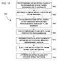
- FIG. 17is a flow chart illustrating an exemplary fluid breakup and spray formation process of the present technique using the spray coating device illustrated in FIGS. 3-15 .
- the present techniqueprovides a refined spray for coating and other spray applications by internally mixing and breaking up the fluid within the spray coating device.
- This internal mixing and breakupis achieved by passing the fluid through one or more varying geometry passages, which may comprises sharp turns, abrupt expansions or contractions, or other mixture-inducing flow paths.
- the present techniquemay flow the fluid through or around a modified needle valve, which has one or more blunt or angled edges, internal flow passages, and varying geometry structures.
- the present techniquemay provide a flow barrier, such as a blockade in the fluid passage, having one or more restricted passages extending therethrough to facilitate fluid mixing and particulate breakup.
- the flow barriermay induce fluid mixing in a mixing cavity between the flow barrier and the modified needle valve.
- the flow barrieralso may create fluid jets from the one or more restricted passages, such that particulate/ligaments in the fluid flow breaks up as the fluid jets impinge against a surface or impinge against one another.
- the present techniquealso may optimize the internal mixing and breakup for a particular fluid and spray application by varying the impingement angles and velocities of the fluid jets, varying the flow passage geometries, modifying the needle valve structure, and varying the spray formation mechanism for producing a spray.
- FIG. 1is a flow chart illustrating an exemplary spray coating system 10 , which comprises a spray coating device 12 for applying a desired coating to a target object 14 .
- the spray coating device 12may be coupled to a variety of supply and control systems, such as a fluid supply 16 , an air supply 18 , and a control system 20 .
- the control system 20facilitates control of the fluid and air supplies 16 and 18 and ensures that the spray coating device 12 provides an acceptable quality spray coating on the target object 14 .
- the control system 20may include an automation system 22 , a positioning system 24 , a fluid supply controller 26 , an air supply controller 28 , a computer system 30 , and a user interface 32 .
- the control system 20also may be coupled to a positioning system 34 , which facilitates movement of the target object 14 relative to the spray coating device 12 .
- the spray coating system 10may provide a computer-controlled mixture of coating fluid, fluid and air flow rates, and spray pattern.
- the positioning system 34may include a robotic arm controlled by the control system 20 , such that the spray coating device 12 covers the entire surface of the target object 14 in a uniform and efficient manner.
- the spray coating system 10 of FIG. 1is applicable to a wide variety of applications, fluids, target objects, and types/configurations of the spray coating device 12 .
- a usermay select a desired fluid 40 from a plurality of different coating fluids 42 , which may include different coating types, colors, textures, and characteristics for a variety of materials such as metal and wood.
- the useralso may select a desired object 36 from a variety of different objects 38 , such as different material and product types.
- the spray coating device 12also may comprise a variety of different components and spray formation mechanisms to accommodate the target object 14 and fluid supply 16 selected by the user.
- the spray coating device 12may comprise an air atomizer, a rotary atomizer, an electrostatic atomizer, or any other suitable spray formation mechanism.
- FIG. 2is a flow chart of an exemplary spray coating process 100 for applying a desired spray coating to the target object 14 .
- the process 100proceeds by identifying the target object 14 for application of the desired fluid (block 102 ).
- the process 100then proceeds by selecting the desired fluid 40 for application to a spray surface of the target object 14 (block 104 ).
- a usermay then proceed to configure the spray coating device 12 for the identified target object 14 and selected fluid 40 (block 106 ).
- the process 100then proceeds to create an atomized spray of the selected fluid 40 (block 108 ).
- the usermay then apply a coating of the atomized spray over the desired surface of the target object 14 (block 110 ).
- the process 100then proceeds to cure/dry the coating applied over the desired surface (block 112 ). If an additional coating of the selected fluid 40 is desired by the user at query block 114 , then the process 100 proceeds through blocks 108 , 110 , and 112 to provide another coating of the selected fluid 40 . If the user does not desire an additional coating of the selected fluid at query block 114 , then the process 100 proceeds to query block 116 to determine whether a coating of a new fluid is desired by the user. If the user desires a coating of a new fluid at query block 116 , then the process 100 proceeds through blocks 104 - 114 using a new selected fluid for the spray coating. If the user does not desire a coating of a new fluid at query block 116 , then the process 100 is finished at block 118 .
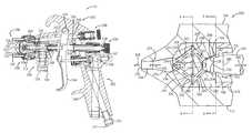
- FIG. 3is a cross-sectional side view illustrating an exemplary embodiment of the spray coating device 12 .
- the spray coating device 12comprises a spray tip assembly 200 coupled to a body 202 .
- the spray tip assembly 200includes a fluid delivery tip assembly 204 , which may be removably inserted into a receptacle 206 of the body 202 .
- a plurality of different types of spray coating devicesmay be configured to receive and use the fluid delivery tip assembly 204 .
- the spray tip assembly 200also includes a spray formation assembly 208 coupled to the fluid delivery tip assembly 204 .
- the spray formation assembly 208may include a variety of spray formation mechanisms, such as air, rotary, and electrostatic atomization mechanisms.
- the illustrated spray formation assembly 208comprises an air atomization cap 210 , which is removably secured to the body 202 via a retaining nut 212 .
- the air atomization cap 210includes a variety of air atomization orifices, such as a central atomization orifice 214 disposed about a fluid tip exit 216 from the fluid delivery tip assembly 204 .
- the air atomization cap 210also may have one or more spray shaping orifices, such as spray shaping orifices 218 , 220 , 222 , and 224 , which force the spray to form a desired spray pattern (e.g., a flat spray).
- the spray formation assembly 208also may comprise a variety of other atomization mechanisms to provide a desired spray pattern and droplet distribution.
- the body 202 of the spray coating device 12includes a variety of controls and supply mechanisms for the spray tip assembly 200 .
- the body 202includes a fluid delivery assembly 226 having a fluid passage 228 extending from a fluid inlet coupling 230 to the fluid delivery tip assembly 204 .
- the fluid delivery assembly 226also comprises a fluid valve assembly 232 to control fluid flow through the fluid passage 228 and to the fluid delivery tip assembly 204 .
- the illustrated fluid valve assembly 232has a needle valve 234 extending movably through the body 202 between the fluid delivery tip assembly 204 and a fluid valve adjuster 236 .
- the fluid valve adjuster 236is rotatably adjustable against a spring 238 disposed between a rear section 240 of the needle valve 234 and an internal portion 242 of the fluid valve adjuster 236 .
- the needle valve 234is also coupled to a trigger 244 , such that the needle valve 234 may be moved inwardly away from the fluid delivery tip assembly 204 as the trigger 244 is rotated counter clockwise about a pivot joint 246 .
- any suitable inwardly or outwardly openable valve assemblymay be used within the scope of the present technique.
- the fluid valve assembly 232also may include a variety of packing and seal assemblies, such as packing assembly 248 , disposed between the needle valve 234 and the body 202 .
- An air supply assembly 250is also disposed in the body 202 to facilitate atomization at the spray formation assembly 208 .
- the illustrated air supply assembly 250extends from an air inlet coupling 252 to the air atomization cap 210 via air passages 254 and 256 .
- the air supply assembly 250also includes a variety of seal assemblies, air valve assemblies, and air valve adjusters to maintain and regulate the air pressure and flow through the spray coating device 12 .
- the illustrated air supply assembly 250includes an air valve assembly 258 coupled to the trigger 244 , such that rotation of the trigger 244 about the pivot joint 246 opens the air valve assembly 258 to allow air flow from the air passage 254 to the air passage 256 .
- the air supply assembly 250also includes an air valve adjustor 260 coupled to a needle 262 , such that the needle 262 is movable via rotation of the air valve adjustor 260 to regulate the air flow to the air atomization cap 210 .
- the trigger 244is coupled to both the fluid valve assembly 232 and the air valve assembly 258 , such that fluid and air simultaneously flow to the spray tip assembly 200 as the trigger 244 is pulled toward a handle 264 of the body 202 .
- the spray coating device 12produces an atomized spray with a desired spray pattern and droplet distribution.
- the illustrated spray coating device 12is only an exemplary device of the present technique. Any suitable type or configuration of a spraying device may benefit from the unique fluid mixing, particulate breakup, and refined atomization aspects of the present technique.
- FIG. 4is a cross-sectional side view of the fluid delivery tip assembly 204 .
- the fluid delivery tip assembly 204comprises a fluid breakup section 266 and a fluid mixing section 268 disposed within a central passage 270 of a housing 272 , which may be removably inserted into the receptacle 206 of the body 202 .
- the central passage 270Downstream of the fluid breakup section 266 , the central passage 270 extends into a fluid tip exit passage 274 , which has a converging section 276 followed by a constant section 278 adjacent the fluid tip exit 216 .
- Any other suitable fluid tip exit geometryis also within the scope of the present technique.
- the needle valve 234controls fluid flow into and through the fluid delivery tip assembly 204 .
- the needle valve 234comprises a needle tip 280 having an abutment surface 282 , which is removably sealable against an abutment surface 284 of the fluid mixing section 268 . Accordingly, as the user engages the trigger 244 , the needle valve 234 moves inwardly away from the abutment surface 284 as indicated by arrow 286 . The desired fluid then flows through the fluid delivery tip assembly 204 and out through the fluid tip exit 216 to form a desired spray via the spray formation assembly 208 .
- the fluid breakup and mixing sections 266 and 268are configured to facilitate fluid mixing and the breakup of particulate/ligaments within the desired fluid prior to exiting through the fluid tip exit 216 . Accordingly, the present technique may utilize a variety of structures, passageways, angles, and geometries to facilitate fluid mixing and particulate breakup within the fluid delivery tip assembly 204 prior to external atomization via the spray formation assembly 208 .
- the fluid mixing section 268has a mixing cavity 288 disposed adjacent a blunt edge 290 of the needle tip 280 , such that fluid flowing past the blunt edge 290 is induced to mix within the mixing cavity 288 .
- Fluid mixingis relatively strong within the mixing cavity 288 due to the velocity differential between the fluid flowing around the needle tip 280 and the substantially blocked fluid within the mixing cavity.
- blunt edge 290provides a relatively sharp interface between the high and low speed fluid flows, thereby facilitating swirl and vortical structures within the fluid flow. Any other suitable mixture-inducing structure is also within the scope of the present technique.
- the mixing cavity 288extends into and through the fluid breakup section 266 via one or more fluid passageways.
- the fluid breakup section 266comprises a diverging passing section 292 coupled to the mixing cavity 288 , a converging passage section 294 coupled to the diverging passage section 292 , and a fluid impingement region 296 positioned downstream of the converging passage section 294 .
- the diverging passage section 292comprises passages 298 , 300 , 302 , and 304 , which diverge outwardly from the mixing cavity 288 toward an annular passageway 306 disposed between the diverging and converging passage sections 292 and 294 .
- the converging passage section 294comprises passages 308 , 310 , 312 , and 314 , which converge inwardly from the annular passage 306 toward the fluid impingement region 296 .
- the desired fluidflows through the central passage 270 , through the mixing cavity 288 , through the passages 298 - 304 of the diverging passage section 292 , through the passages 308 - 314 of the converging passage section 294 , into the fluid impingement region 296 as fluid jets convergingly toward one another, through the fluid tip exit passage 274 , and out through the fluid tip exit 216 , as indicated by arrows 316 , 318 , 320 , 322 , 324 , 326 , and 328 , respectively.
- the fluid breakup section 266may have any suitable configuration of passages directed toward a surface or toward one another, such that the fluid collides/impinges in a manner causing particulate/ligaments in the fluid to break
- FIG. 5is a partial cross-sectional side view of the fluid delivery tip assembly 204 further illustrating the needle valve 234 , the fluid mixing section 268 , and the diverging passage section 292 .
- the desired fluidflows around the needle tip 280 and swirls past the blunt edge 290 , as indicated by arrows 316 and 330 , respectively.
- the blunt edge 290 of the needle tip 280induces fluid mixing downstream of the needle valve 234 .
- the blunt edge 290may facilitate turbulent flows and fluid breakup within the fluid mixing section 268 .
- the mixing section 268may induce fluid mixing by any suitable sharp or blunt edged structure, abruptly expanding or contracting passageway, or any other mechanism producing a velocity differential that induces fluid mixing.
- the fluidflows into the fluid mixing section 268 , the fluid collides against a flow barrier 332 , which has an angled surface 334 extending to a vertical surface 336 .
- the flow barrier 332reflects a substantial portion of the fluid flow back into the fluid mixing section 268 , such that the fluid flow swirls and generally mixes within the fluid mixing section 268 , as indicated by arrows 338 .
- the mixed fluidthen flows from the fluid mixing section 268 into the fluid breakup section 266 via the passages 298 , 300 , 302 , and 304 , as indicated by arrows 320 .
- the passages 298 - 304have a relatively smaller geometry than the mixing cavity 288 .
- This abruptly contracting flow geometryeffectively slows the flow within the fluid mixing section 268 and forces the fluid to mix prior to moving forward through the fluid breakup section 266 .
- the abruptly contracting flow geometryalso accelerates the fluid flow through the fluid breakup section 266 , thereby creating relatively high speed fluid jets that are directed toward an impingement region.
- FIG. 6is a cross-sectional face view of the fluid mixing section 268 illustrated by FIG. 4 .
- the fluidflows into the fluid mixing section 268 and strikes the flow barrier 332 , as indicated by arrows 318 .
- some of the fluidmay be directed straight into the passages 300 - 304 , a significant portion of the fluid strikes the angled and vertical surfaces 334 and 336 of the flow barrier 332 surrounding the passages 300 - 304 .
- the flow barrier 332reflects and slows the fluid flow, such that the fluid mixes within the fluid mixing section 268 . Fluid mixing is also induced by the geometry of the needle valve 234 .
- the blunt edge 290creates a velocity differential that facilitates fluid mixing between the fluid entering the fluid mixing section 268 and the fluid substantially blocked within the fluid mixing section 268 .
- the mixing induced by the flow barrier 332 and the blunt edge 290may provide a more homogenous mixture of the desired fluid, while also breaking down particulate within the fluid.
- any suitable mixture-inducing geometryis within the scope of the present technique.
- FIG. 7is a partial cross-sectional side view of the fluid mixing section 268 of FIG. 5 rotated 45 degrees as indicated by FIG. 6 .
- the fluiddoes not flow directly into the passages 300 - 304 , but rather the fluid strikes and reflects off of the flow barrier 332 , as indicated by arrows 338 . Accordingly, the fluid is mixed and broken up into a more consistent mixture within the fluid mixing section 268 .
- the present techniquemay have any suitable size, geometry, or structure for the mixing cavity 288 , the flow barrier 332 , and the needle tip 280 .
- the particular angles and flow capacities within the fluid mixing section 268may be selected to facilitate fluid mixing and breakup for a particular fluid and spraying application.
- Certain fluid characteristics, such as viscosity and degree of fluid particulate,may require a certain flow velocity, passage size, and other specific structures to ensure optimal fluid mixing and breakup through the spray coating device 12 .
- FIG. 8is a cross-sectional face view of the angular passage 306 illustrating fluid flow between the passages entering and exiting the annular passage 306 via the diverging and converging sections 292 and 294 .
- fluidflows from the fluid mixing section 268 to the annular passage 306 via the passages 298 - 304 of the diverging passage section 292 .
- the annular passage 306substantially frees/unrestricts the fluid flow relative to the restricted geometries of the passages 300 - 304 . Accordingly, the annular passage 306 unifies and substantially equalizes the fluid flow, as indicated by arrows 340 .
- the substantially equalized fluid flowthen enters the passages 308 - 314 of the converging passage section 294 , where the fluid flow is directed inwardly toward the fluid impingement region 296 .
- the present techniquemay have any suitable form of intermediate region between the diverging and converging passage sections 292 and 294 . Accordingly, the passages 298 - 304 may be separately or jointly coupled to passages 308 - 314 via any suitable interface.
- the present techniquealso may utilize any desired number of passages through the converging and diverging sections 292 and 294 . For example, a single passage may extend through the diverging passage section 292 , while one or multiple passages may extend through the converging passage section 294 .
- FIG. 9is a partial cross-sectional side view of the fluid breakup section 266 illustrating the converging passage section 294 and the fluid impingement region 296 .
- the fluidflows through passages 308 - 314 of the converging passage section 294 inwardly toward the fluid impingement region 296 , such that the fluid collides at a desired angle.
- the passages 308 - 314may be directed toward an impingement point 342 at an impingement angle 344 relative to a centerline 346 of the fluid breakup section 266 .
- the impingement angle 344may be selected to optimize fluid breakup based on characteristics of a particular fluid, desired spray properties, a desired spray application, and various other factors.
- the selected impingement angle 344 , geometries of the passages 308 - 314 , and other application-specific factorscollectively optimize the collision and breakup of fluid particulate/ligaments within the fluid impingement region 296 .
- the impingement angle 344may be in a range of 25-45 degrees.
- an impingement angle of approximately 37 degreesmay be selected to optimize fluid particulate breakup. If the fluid jets are impinged toward one another as illustrated in FIG. 9 , then the impingement angle may be in a range of 50-90 degrees between the fluid jets flowing from the passages 308 - 314 .
- the fluid impingement region 296also may be disposed within a recess of the converging passage section 294 , such as a conic cavity 348 .
- FIG. 10is a cross-sectional side view of the fluid delivery tip assembly 204 illustrating an alternative embodiment of the fluid breakup section 266 .
- the fluid breakup section 266includes the diverging passage section 292 adjacent an annular spacer 350 without the converging passage section 294 .
- fluidflows past the needle tip 280 , through the fluid mixing section 268 , through the passages of 298 - 304 of the diverging passage section 292 , colliding onto an interior of the annular spacer 350 at an impingement angle 352 , through the central passage 270 within the annular spacer 350 , and out through the fluid tip exit passage 274 , as indicated by arrows 316 , 318 , 320 , 354 , and 326 , respectively.
- impinging fluid jetsare ejected from the passages 298 - 304 of the diverging passage section 292 , rather than from the passages 308 - 314 of the converging passage section 294 .
- These relatively high speed fluid jetsthen impinge a surface (i.e., the interior of the annular spacer 350 ), rather than impinging one another.
- the impingement angle 352is selected to facilitate fluid breakup of particulate/ligaments based on the fluid characteristics and other factors. Accordingly, the impingement angle 352 may be within any suitable range, depending on the application.
- the particular impingement angle 352may be selected to optimize fluid breakup for a particular coating fluid, such as a wood stain, and a particular spraying application. As discussed above, the impingement angle 352 may be in a range of 25-45 degrees, or approximately 37 degrees, for a particular application. It also should be noted that the present technique may use any one or more surface impinging jets, such as those illustrated in FIG. 10 . For example, a single impinging jet may be directed toward a surface of the annular spacer 350 .
- the fluid breakup section 266also may have multiple fluid jets directed toward one another or toward one or more shared points on the interior surface of the annular spacer 350 .
- the spray coating device 12may have a variety of different valve assemblies 232 to facilitate fluid mixing and breakup in the fluid delivery tip assembly 204 .
- one or more mixture-inducing passages or structuresmay be formed on or within the needle valve 234 to induce fluid mixing.
- FIGS. 11-15illustrate several exemplary needle valves, which may enhance fluid mixing in the fluid mixing section 268 .
- FIG. 11is a cross-sectional side view of the fluid delivery tip assembly 204 illustrating an alternative embodiment of the needle valve 234 and the fluid breakup and mixing sections 266 and 268 .
- the illustrated fluid breakup section 266has the converging passage section 294 without the diverging passage section 292 .
- the illustrated fluid mixing section 268has a vertical flow barrier 356 within an annular mixing cavity 358 , rather than having the multi-angled mixing cavity 288 illustrated by FIG. 4 .
- the annular cavity 358also has a stepped portion 360 for sealing engagement with the needle valve 234 in a closed position.
- the illustrated needle valve 234also has a blunt tip 362 to facilitate mixing within the fluid mixing section 268 .
- the needle valve 234In an open position of the needle valve 234 , fluid flows around the needle valve 234 , past the blunt tip 362 , into the passages 308 - 314 of the converging passage section 294 , and convergingly inward toward the impingement point 342 within the fluid impingement region 296 , as indicated by arrows 364 , 366 , 322 , and 324 , respectively.
- the blunt tip 362 of the needle valve 234facilitates fluid swirl and general mixing, as illustrated by arrows 366 .
- the flow barrier 356also facilitates fluid mixing within the fluid mixing section 268 between the flow barrier 356 and the blunt tip 362 of the needle valve 234 .
- the flow barrier 356restricts the fluid flow into the restricted geometries of the passages 308 - 314 , thereby creating relatively high speed fluid jets ejecting into the fluid impingement region 296 .
- the impingement angles 344 of these fluid jets and passages 308 - 314are selected to facilitate fluid breakup for a particular fluid and application. For example, a particular fluid may breakup more effectively at a particular collision/impingement angle and velocity, such as an angle of approximately 37 degrees relative to the centerline 346 .
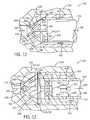
- FIG. 12is a cross-sectional side view of the fluid delivery tip assembly 204 illustrating another alternative embodiment of the needle valve 234 and the fluid breakup and mixing sections 266 and 268 .
- the fluid breakup section 266has a converging passage section 368 , which has passages 370 extending from the fluid mixing section 268 convergingly toward a conical cavity 372 .
- the fluid mixing section 268comprises an annular cavity 374 between a blunt tip 376 of the needle valve 234 and a vertical flow barrier 378 formed at an entry side of the converging passage section 368 .
- the annular cavity 374has a stepped portion 380 , which is sealable against the needle valve 234 in a closed position.
- the needle valve 234has a shaft 382 extending moveably through a central passage 384 of the converging passage section 368 .
- the needle valve 234has a wedge shaped head 386 extending from the shaft 382 .
- the wedge shaped head 386is positionable within an impingement region 388 in the conical cavity 372 .
- fluidflows along the needle valve 234 , past the blunt tip 376 in a swirling motion, through the passages 370 in an impinging path toward the wedge shaped head 386 , and out through the fluid tip exit passage 274 , as indicated by arrows 364 , 366 , 390 , and 326 , respectively.
- the blunt tip 376 and the vertical flow barrier 378facilitate fluid mixing and breakup within the fluid mixing section 268 .
- the fluid jets ejecting from the passages 370impinge against the wedge shaped head 386 to facilitate the breakup of fluid particulate/ligaments within the fluid.
- the particular impingement angle of the fluid jets colliding with the wedge shaped head 386may be selected based on the fluid characteristics and desired spray application.
- the particular size and geometry of the passages 370may be selected to facilitate a desired velocity of the fluid jets.
- the configuration and structure of the shaft 382 and head 386also may be modified within the scope of the present technique.
- the head 386may have a disk-shape, a wedge-shape at the impingement side, one or more restricted passages extending therethrough, or the head 386 may have a hollow muffler-like configuration.
- the shaft 382may have a solid structure, a hollow structure, a multi-shaft structure, or any other suitable configuration.
- FIG. 13is a cross-sectional side view of the fluid delivery tip assembly 204 illustrating an alternative embodiment of the needle valve 234 .
- the fluid delivery tip assembly 204comprises the fluid breakup section 266 adjacent the converging passage section 294 without the diverging passage section 292 .
- the alternative needle valve 234 illustrated in FIG. 13may be used with any configuration of the fluid breakup section 266 and the fluid mixing section 268 .
- the fluid mixing section 268comprises an annular mixing cavity 392 disposed between the needle valve 234 and a vertical flow barrier 394 at an entry side of the converging passage section 294 .
- the illustrated needle valve 234comprises a hollow shaft 396 having a central passage 398 and a plurality of entry and exit ports.
- the hollow shaft 396has a plurality of lateral entry ports 400 and a central exit port 402 , which facilitates fluid mixing as the fluid flows past the entry and exit ports 400 and 402 .
- the ports 400 and 402create an abrupt contraction and expansion in the fluid flow path, such that ring vortices form and mixing is induced downstream of the ports 400 and 402 .
- the needle valve 234shuts off the fluid flow by positioning a valve tip 404 against the vertical flow barrier 394 , such that fluid flow cannot enter the passages 308 - 314 .
- the needle valve 234opens the fluid flow by moving the hollow shaft 396 outwardly from the vertical flow barrier 394 , thereby allowing fluid to flow through the passages 308 - 314 .
- fluidflows around the hollow shaft 396 , in through the ports 400 , through the central passage 398 , out through the port 402 and into the fluid mixing section 268 , swirlingly past the port 402 at the abrupt expansion region, through the passages 308 - 314 , convergingly into the impingement region 296 , and out through the fluid tip exit passage 274 , as indicated by arrows 406 , 408 , 410 , 412 , 322 , 324 , and 326 , respectively.
- the abruptly constricted and expanded geometries of the passages and ports extending through the hollow shaft 396facilitates fluid mixing into the fluid mixing section 268 , which further mixes the fluid flow prior to entry into the converging passage section 294 .
- the fluid flowthen increases velocity as it is restricted through the passages 308 - 314 , thereby facilitating relatively high speed fluid collision in the fluid impingement region 296 .
- FIG. 13illustrates specific flow passages and geometries, the present technique may use any suitable flow geometries and passages through the needle valve 234 and the breakup and mixing sections 266 and 268 to facilitate pre-atomization fluid mixing and breakup of the fluid.
- FIG. 14is a cross-sectional side view of the fluid delivery tip assembly 204 illustrating an alternative multi-component needle valve 234 .
- the illustrated needle valve 234comprises a needle body section 414 coupled to a needled tip section 416 via a connector 418 , which may comprise an externally threaded member or any other suitable fastening device.
- the needle body section 414may be formed from stainless steel, aluminum, or any other suitable material, while the needle tip section 416 may be formed from plastic, metal, ceramic, Delrin, or any other suitable material.
- the needle tip section 416may be replaced with a different needle tip section to accommodate a different configuration of the fluid delivery tip assembly 204 or to refurbish the needle valve 234 after significant wear.
- the needle valve 234 illustrated by FIG. 14may be used with any configuration of the fluid breakup section 266 and the fluid mixing section 268 .
- the illustrated fluid breakup section 266may comprise any one or both of the diverging or converging passage sections 292 and 294 or any other suitable fluid mixing and breakup configuration. Again the impingement angles in the fluid breakup section 266 may be selected to accommodate a particular coating fluid and spray application.
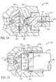
- FIG. 15is a cross-sectional side view of the fluid delivery tip assembly 204 illustrating an alternative embodiment of the needle valve 234 and the fluid breakup and mixing sections 266 and 268 .
- the fluid breakup section 266comprises a converging passage section 420
- the fluid mixing section 268has a wedge shaped mixing cavity 422 between the converging passage section 420 and the needle valve 234 .
- the converging passage section 420has passages 424 extending convergingly from a vertical flow barrier 426 in the wedge shaped mixing cavity 422 toward a fluid impingement region 428 adjacent the fluid tip exit passage 274 .
- the needle valve 234controls the fluid flow through the fluid delivery tip assembly 204 by moving the needle tip 280 inwardly and outwardly from the wedge shaped mixing cavity 422 .
- fluidflows around the needle tip 280 , mixingly past the blunt edge 290 , through the wedge shaped mixing cavity 422 and against the vertical flow barrier 426 , through the passages 424 , and convergingly inward toward one another in the fluid impingement region 428 , and out through the fluid tip exit passage 274 , as indicated by arrows 430 , 432 , 434 , 436 , 438 , and 326 , respectively.
- the blunt edge 290facilitates fluid mixing past the needle tip 280 by inducing swirling/mixing based on the velocity differential.
- the converging passage section 420further mixes and breaks up the fluid flow by restricting the fluid flow into the passages 424 , thereby increasing the fluid velocity and forcing the fluid to eject as fluid jets that impinge one another in the fluid impingement region 428 .
- the impingement of the fluid jets in the fluid impingement region 428then forces the particulate/ligaments within the fluid to breakup into finer particulate prior to atomization by the spray formation assembly 208 .
- the present techniquemay select any suitable impingement angle within the scope of the present technique.
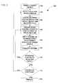
- FIG. 16is a flow chart illustrating an exemplary spray coating process 500 .
- the process 500proceeds by identifying a target object for application of a spray coating (block 502 ).
- the target objectmay comprise a variety of materials and products, such as wood or metal furniture, cabinets, automobiles, consumer products, etc.
- the process 500then proceeds to select a desired fluid for coating a spray surface on the target object (block 504 ).
- the desired fluidmay comprise a primer, a paint, a stain, or a variety of other fluids suitable for a wood, a metal, or any other material of the target object.
- the processthen proceeds to select a spray coating device to apply the desired fluid to the target object (block 506 ).
- a particular type and configuration of a spray coating devicemay be more effective at applying a spray coating of the desired fluid onto the target object.
- the spray coating devicemay be a rotary atomizer, an electrostatic atomizer, an air jet atomizer, or any other suitable atomizing device.
- the process 500then proceeds to select an internal fluid mixing/breakup section to facilitate breakup of particulate/ligaments (block 508 ).
- the process 500may select any one or a combination of the valve assemblies, diverging passage sections, converging passage sections, and fluid mixing sections discussed with reference to FIGS. 3-15 .
- the process 500then proceeds to configure the spray coating device with the selected one or more mixing/breakup sections for the target object and selected fluid (block 510 ).
- the selected mixing/breakup sectionsmay be disposed within an air atomization type spray coating device or any other suitable spray coating device.
- the process 500proceeds to position the spray coating device over the target object (block 512 ).
- the process 500also may utilize a positioning system to facilitate movement of the spray coating device relative to the target object, as discussed above with reference to FIG. 1 .
- the process 500then proceeds to engage the spray coating device ( 514 ).
- a usermay pull a trigger 244 or the control system 20 may automatically engage the spray coating device.
- the process 500feeds the selected fluid into the spray coating device at block 516 and breaks up the fluid particulate in the mixing/breakup section at block 518 . Accordingly, the process 500 refines the selected fluid within the spray coating device prior to the actual spray formation.
- the process 500creates a refined spray having reduced particulate/ligaments.
- the process 500then proceeds to apply a coating of the refined spray to the spray surface of the target object (block 522 ).
- the processcures/dries the applied coating to the spray surface of the target object. Accordingly, the spray coating process 500 produces a refined spray coating at block 526 .
- the refined spray coatingmay be characterized by a refined and relatively uniform texture and color distribution, a reduced mottling effect, and various other refined characteristics within the spray coating.
- FIG. 17is a flow chart illustrating an exemplary fluid breakup and spray formation process 600 .
- the process 600proceeds by inducing mixing of a selected fluid at one or more blunt/angled structures and/or passages of a fluid valve (block 602 ).
- the process 600may pass the selected fluid through or about any one of the needle valves 234 described above with reference to FIGS. 3-15 .
- Any other suitable hollow or solid fluid valves having blunt/angled structures/passagesalso may be used within the scope of the present technique.
- the process 600then proceeds to restrict the fluid flow of the selected fluid at a flow barrier (block 604 ).
- a vertical or angled surfacemay be extended partially or entirely across a flow passageway through the spray coating device.
- the process 600then proceeds to accelerate the fluid flow of the selected fluid through restricted passageways extending through the flow barrier (block 606 ).
- the processcreates one or more impinging fluid jets from the restricted passageways.
- the process 600then proceeds to breakup particulate/ligaments within the selected fluid at a fluid impingement region downstream of the impinging fluid jets (block 610 ).
- the one or more impinging fluid jetsmay be directed toward one another or toward one or more surfaces at an angle selected to facilitate the breakup of particulate/ligaments.
- the selected fluidis ejected from the spray coating device at block 612 .
- the process 600then proceeds to atomize the selected fluid into a desired spray pattern from the spray coating device (block 614 ).
- the process 600may use any suitable spray formation mechanism to atomize the selected fluid, including rotary atomization mechanisms, air jet atomization mechanisms, electrostatic mechanisms, and various other suitable spray formation techniques.
Landscapes
- Nozzles (AREA)
Abstract
Description
Claims (65)
Priority Applications (9)
| Application Number | Priority Date | Filing Date | Title |
|---|---|---|---|
| US10/223,648US7762476B2 (en) | 2002-08-19 | 2002-08-19 | Spray gun with improved atomization |
| DE60335062TDE60335062D1 (en) | 2002-08-19 | 2003-07-25 | spray gun |
| EP03016939AEP1391246B1 (en) | 2002-08-19 | 2003-07-25 | Spray gun |
| TW092120559ATWI294790B (en) | 2002-08-19 | 2003-07-28 | Spray coating device and method, and method of making the spray coating device |
| KR1020030056208AKR101074842B1 (en) | 2002-08-19 | 2003-08-13 | Spray gun with improved atomization |
| MXPA03007401AMXPA03007401A (en) | 2002-08-19 | 2003-08-18 | Spray gun with improved atomization. |
| CA002437446ACA2437446A1 (en) | 2002-08-19 | 2003-08-18 | Spray gun with improved atomization |
| JP2003295205AJP2004074155A (en) | 2002-08-19 | 2003-08-19 | Improved spray gun for spraying |
| CNB031536719ACN1272109C (en) | 2002-08-19 | 2003-08-19 | Spray gun with improved atomization |
Applications Claiming Priority (1)
| Application Number | Priority Date | Filing Date | Title |
|---|---|---|---|
| US10/223,648US7762476B2 (en) | 2002-08-19 | 2002-08-19 | Spray gun with improved atomization |
Publications (2)
| Publication Number | Publication Date |
|---|---|
| US20040046040A1 US20040046040A1 (en) | 2004-03-11 |
| US7762476B2true US7762476B2 (en) | 2010-07-27 |
Family
ID=31187960
Family Applications (1)
| Application Number | Title | Priority Date | Filing Date |
|---|---|---|---|
| US10/223,648Expired - Fee RelatedUS7762476B2 (en) | 2002-08-19 | 2002-08-19 | Spray gun with improved atomization |
Country Status (9)
| Country | Link |
|---|---|
| US (1) | US7762476B2 (en) |
| EP (1) | EP1391246B1 (en) |
| JP (1) | JP2004074155A (en) |
| KR (1) | KR101074842B1 (en) |
| CN (1) | CN1272109C (en) |
| CA (1) | CA2437446A1 (en) |
| DE (1) | DE60335062D1 (en) |
| MX (1) | MXPA03007401A (en) |
| TW (1) | TWI294790B (en) |
Cited By (11)
| Publication number | Priority date | Publication date | Assignee | Title |
|---|---|---|---|---|
| US20060000928A1 (en)* | 2004-06-30 | 2006-01-05 | Micheli Paul R | Fluid atomizing system and method |
| US20100006673A1 (en)* | 2004-06-30 | 2010-01-14 | Illinois Tool Works Inc. | Fluid atomizing system and method |
| US8590810B2 (en) | 2009-02-26 | 2013-11-26 | Sarah Jane Woodgate | Spray gun |
| US8690083B2 (en) | 2010-10-20 | 2014-04-08 | Finishing Brands Holdings Inc. | Adjustable needle packing assembly for a spray gun |
| US8814070B2 (en) | 2010-10-20 | 2014-08-26 | Finishing Brands Holdings, Inc. | Fine finish airless spray tip assembly for a spray gun |
| US8960570B2 (en) | 2010-10-20 | 2015-02-24 | Finishing Brands Holdings Inc. | Twist tip air cap assembly including an integral sleeve for a spray gun |
| US9216430B2 (en) | 2011-09-30 | 2015-12-22 | Carlisle Fluid Technologies, Inc. | Spray device having curved passages |
| US9302281B2 (en) | 2011-01-24 | 2016-04-05 | Carlisle Fluid Technologies, Inc. | High swirl air cap |
| US9630196B2 (en) | 2013-01-24 | 2017-04-25 | Graco Minnesota Inc. | Airflow control for an integrated handheld texture sprayer |
| US10167641B2 (en) | 2013-01-24 | 2019-01-01 | Graco Minnesota, Inc. | Air control trigger for integrated handheld texture sprayer |
| US11541406B2 (en) | 2020-03-30 | 2023-01-03 | Medmix Switzerland Ag | Spray nozzle |
Families Citing this family (27)
| Publication number | Priority date | Publication date | Assignee | Title |
|---|---|---|---|---|
| US6808122B2 (en)* | 2002-08-19 | 2004-10-26 | Illinois Tool Works, Inc. | Spray gun with improved pre-atomization fluid mixing and breakup |
| US7762476B2 (en) | 2002-08-19 | 2010-07-27 | Illinois Tool Works Inc. | Spray gun with improved atomization |
| US6935577B2 (en)* | 2003-02-28 | 2005-08-30 | Illinois Tool Works Inc. | One-piece fluid nozzle |
| US7568635B2 (en)* | 2004-09-28 | 2009-08-04 | Illinois Tool Works Inc. | Turbo spray nozzle and spray coating device incorporating same |
| EP1896188B1 (en)* | 2005-06-29 | 2010-08-18 | Boehringer Ingelheim International GmbH | Method and device for atomising liquid |
| US7389945B2 (en)* | 2005-09-15 | 2008-06-24 | Kuan Chang Co., Ltd. | Spray paint gun structure having a coaxial control of fluid and atomization |
| GB2430635A (en)* | 2005-10-01 | 2007-04-04 | Pursuit Dynamics Plc | An atomising apparatus |
| US8684281B2 (en)* | 2006-03-24 | 2014-04-01 | Finishing Brands Holdings Inc. | Spray device having removable hard coated tip |
| US20080017734A1 (en)* | 2006-07-10 | 2008-01-24 | Micheli Paul R | System and method of uniform spray coating |
| JP5293989B2 (en)* | 2007-07-24 | 2013-09-18 | ノードソン株式会社 | Small liquid spray equipment |
| CA2742971A1 (en)* | 2008-11-05 | 2010-05-14 | Illinois Tool Works Inc. | Spray gun having protective liner and light trigger pull |
| EP2189225B1 (en)* | 2008-11-19 | 2012-12-12 | J. Wagner GmbH | Colour spray gun with beam distortion |
| US8789770B2 (en)* | 2008-12-18 | 2014-07-29 | Graco Minnesota Inc. | Tooless needle change spray gun |
| GB2491929B (en) | 2011-06-17 | 2017-07-26 | Earlex Ltd | Spray gun |
| JP5787409B2 (en)* | 2012-08-10 | 2015-09-30 | アネスト岩田株式会社 | Spray gun |
| EP3021982B1 (en)* | 2013-07-15 | 2020-02-26 | 3M Innovative Properties Company | Air caps with face geometry inserts for liquid spray guns |
| CN104624421A (en)* | 2014-05-08 | 2015-05-20 | 孙永虎 | Multi-head spray gun |
| KR101661575B1 (en)* | 2014-10-22 | 2016-10-04 | (주)연우 | Spray orifice structure |
| KR101692347B1 (en)* | 2015-04-17 | 2017-01-03 | 주식회사 에스엠뿌레 | Sprayer and spray control apparatus |
| FR3055818A1 (en) | 2016-09-14 | 2018-03-16 | Exel Industries | DEVICE FOR ROTATING A FLUID WITHIN A NOZZLE, ASSEMBLY COMPRISING SUCH DEVICE AND APPLICATION DEVICE |
| FR3073155B1 (en)* | 2017-11-07 | 2020-09-11 | Exel Ind | SPRAY NOZZLE WITH PRE-ATOMIZATION SHRINKAGE, AND SPRAY HEAD AND SPRAY DEVICE INCLUDING SUCH A NOZZLE |
| EP3578269B1 (en) | 2018-06-04 | 2022-08-31 | Gjosa SA | Cartridge, method for operating the cartridge, water nozzle insert and outlet |
| MX2020013891A (en) | 2018-06-21 | 2021-03-09 | Procter & Gamble | Unitary dispensing nozzle for co-injection of two or more liquids and method of using same. |
| JP7443515B2 (en) | 2019-12-16 | 2024-03-05 | ザ プロクター アンド ギャンブル カンパニー | Liquid dispensing system with integrated dispensing nozzle |
| CN114522818A (en)* | 2022-02-21 | 2022-05-24 | 上海高仙自动化科技发展有限公司 | Curing agent spraying mechanism and intelligent stone nursing robot |
| KR102443969B1 (en)* | 2022-05-11 | 2022-09-19 | (주)티씨케이 | A portable, economical vacuum inspection test gun with a small amount of helium that can be precisely sprayed. |
| CN115301431B (en)* | 2022-09-14 | 2023-08-15 | 华能国际电力股份有限公司 | High-viscosity slurry atomizing nozzle for inner wall of boiler tube of thermal power unit |
Citations (80)
| Publication number | Priority date | Publication date | Assignee | Title |
|---|---|---|---|---|
| US1650128A (en)* | 1920-04-05 | 1927-11-22 | Babcock & Wilcox Co | Method of and apparatus for spraying liquids |
| US1741169A (en) | 1925-11-06 | 1929-12-31 | Wayne B Thompson | Spray-gun |
| US2246211A (en) | 1938-01-24 | 1941-06-17 | Kilich Conrad | Method of and means for mixing and atomizing liquids |
| US2303280A (en) | 1940-09-09 | 1942-11-24 | Alexander F Jenkins | Spray gun |
| US2307014A (en) | 1939-11-02 | 1943-01-05 | Charles F Becker | Fire hose nozzle |
| US2435605A (en) | 1944-03-31 | 1948-02-10 | Herman L Rowell | Spray nozzle |
| US2566324A (en)* | 1949-11-16 | 1951-09-04 | Specialties Dev Corp | Discharge device for fluids |
| US2595759A (en) | 1948-11-30 | 1952-05-06 | Gen Electric | Atomizing nozzle for spraying viscous liquids |
| US2895685A (en) | 1956-02-29 | 1959-07-21 | Vilbiss Co | Spray nozzle |
| US3032277A (en) | 1959-07-27 | 1962-05-01 | Sherwin Williams Co | Spray gun for multicolor paints |
| US3100084A (en) | 1961-08-01 | 1963-08-06 | Gulf Research Development Co | Constant flow rate fuel injection nozzle |
| US3130910A (en) | 1962-05-21 | 1964-04-28 | Delavan Mfg Company | Hydraulic atomizing spray gun |
| US3190564A (en)* | 1963-03-11 | 1965-06-22 | Atlas Copco Ab | Spray coating apparatus for spraying liquid coating material under high pressure |
| US3344558A (en) | 1965-07-23 | 1967-10-03 | Wyatt S Kirkland | Sand blast nozzle |
| US3521824A (en) | 1968-10-11 | 1970-07-28 | Delavan Manufacturing Co | Air-liquid flat spray nozzle |
| US3734406A (en) | 1971-07-30 | 1973-05-22 | Nordson Corp | Method and apparatus for producing a flat fan paint spray pattern |
| US3746253A (en)* | 1970-09-21 | 1973-07-17 | Walberg & Co A | Coating system |
| US3747851A (en) | 1971-10-27 | 1973-07-24 | Delavan Manufacturing Co | Swirl air nozzle |
| US3857511A (en) | 1973-07-31 | 1974-12-31 | Du Pont | Process for the spray application of aqueous paints by utilizing an air shroud |
| US3907202A (en) | 1973-05-10 | 1975-09-23 | Skm Sa | Spray-gun apparatus for atomizing paint or similar liquids |
| JPS5111A (en) | 1974-06-20 | 1976-01-05 | Toyo Tire & Rubber Co | KONENDOEKIJOBUTSUFUNMUKI |
| US3946947A (en) | 1973-09-11 | 1976-03-30 | Chemtrust Industries Corporation | Foam generating apparatus |
| US4159082A (en) | 1976-10-15 | 1979-06-26 | Firma Ernst Mueller Kg | Spray gun |
| US4260110A (en) | 1977-02-18 | 1981-04-07 | Winfried Werding | Spray nozzle, devices containing the same and apparatus for making such devices |
| US4330086A (en) | 1980-04-30 | 1982-05-18 | Duraclean International | Nozzle and method for generating foam |
| US4406407A (en) | 1981-11-17 | 1983-09-27 | Wm. Steinen Mfg. Co. | High flow low energy solid cone spray nozzle |
| US4485968A (en) | 1982-09-07 | 1984-12-04 | Columbia Chase Corporation | Boiler nozzle |
| US4520962A (en) | 1981-01-30 | 1985-06-04 | Hitachi, Ltd. | Magnetic fuel injection valve |
| US4632314A (en) | 1982-10-22 | 1986-12-30 | Nordson Corporation | Adhesive foam generating nozzle |
| US4646968A (en) | 1985-04-17 | 1987-03-03 | The Dow Chemical Company | Prilling apparatus |
| US4767057A (en) | 1986-02-28 | 1988-08-30 | Sames S.A. | Spray nozzle |
| JPS63319076A (en) | 1987-06-23 | 1988-12-27 | Nippon Ee C Syst Kk | Spray gun |
| US4899937A (en) | 1986-12-11 | 1990-02-13 | Spraying Systems Co. | Convertible spray nozzle |
| US4909443A (en) | 1988-02-27 | 1990-03-20 | Toshio Takagi | Water spraying nozzle |
| US4998672A (en) | 1987-07-20 | 1991-03-12 | Sames S.A. | Manually controlled spraying installation and sprayer |
| US5035358A (en)* | 1989-03-22 | 1991-07-30 | Toyota Jidosha Kabushiki Kaisha | Fuel injector for use in an engine |
| US5072883A (en) | 1990-04-03 | 1991-12-17 | Spraying Systems Co. | Full cone spray nozzle with external air atomization |
| US5074466A (en) | 1990-01-16 | 1991-12-24 | Binks Manufacturing Company | Fluid valve stem for air spray gun |
| US5106025A (en) | 1989-10-03 | 1992-04-21 | Sames, S.A. | Coating product sprayer device with rotary sprayer member |
| US5170941A (en)* | 1989-04-20 | 1992-12-15 | Iwata Air Compressor Mfg. Co., Ltd. | Premixing-type spray gun |
| US5180104A (en)* | 1991-02-20 | 1993-01-19 | Binks Manufacturing Company | Hydraulically assisted high volume low pressure air spray gun |
| US5209405A (en) | 1991-04-19 | 1993-05-11 | Ransburg Corporation | Baffle for hvlp paint spray gun |
| US5249746A (en) | 1990-05-11 | 1993-10-05 | Iwata Air Compressor Mfg. Co., Ltd. | Low pressure paint atomizer-air spray gun |
| US5273059A (en) | 1991-01-31 | 1993-12-28 | MBB Foerd-und Hebesysteme | Apparatus for removing coatings from large surface areas and for cleaning such areas |
| WO1994007607A1 (en) | 1992-09-29 | 1994-04-14 | Boehringer Ingelheim International Gmbh | Atomising nozzle and filter and spray generating device |
| US5319568A (en)* | 1991-07-30 | 1994-06-07 | Jesco Products Co., Inc. | Material dispensing system |
| US5344078A (en) | 1993-04-22 | 1994-09-06 | Ransburg Corporation | Nozzle assembly for HVLP spray gun |
| US5358182A (en) | 1992-06-22 | 1994-10-25 | Sames S.A. | Device with rotating atomizer head for electrostatically spraying liquid coating product |
| EP0630690A1 (en) | 1993-06-15 | 1994-12-28 | Sames S.A. | Air assisted flat jet spraying device for spraying coating material |
| US5419491A (en)* | 1994-05-23 | 1995-05-30 | Mattson Spray Equipment, Inc. | Two component fluid spray gun and method |
| US5553784A (en) | 1994-12-09 | 1996-09-10 | Hago Industrial Corp. | Distributed array multipoint nozzle |
| US5669967A (en) | 1996-05-30 | 1997-09-23 | Engelhard Corporation | Pigment compositions |
| US5685482A (en) | 1993-08-09 | 1997-11-11 | Sickles; James E. | Induction spray charging apparatus |
| US5685495A (en) | 1992-12-01 | 1997-11-11 | Sames S.A. | Device for projecting a coating product having a rotary spraying element and tool for fitting and removing such rotary element |
| US5699967A (en)* | 1995-08-25 | 1997-12-23 | Campbell Hausfeld/Scott Fetzer Co. | Airless spray gun diffuser |
| JPH1194494A (en) | 1997-09-17 | 1999-04-09 | Apollo Denki:Kk | Method for washing car air-conditioning equipment |
| US5899387A (en) | 1997-09-19 | 1999-05-04 | Spraying Systems Co. | Air assisted spray system |
| WO2000000770A1 (en) | 1998-06-26 | 2000-01-06 | Pratt & Whitney Canada Corp. | Fuel injector for gas turbine engine |
| US6021962A (en)* | 1995-10-16 | 2000-02-08 | Graves Spray Supply, Inc | Air assisted resin spray nozzle |
| US6045057A (en) | 1997-05-29 | 2000-04-04 | Moor; Ronald C. | Method and apparatus for spray applying fiber-reinforced resins with high ceramic fiber loading |
| US6085996A (en) | 1998-03-05 | 2000-07-11 | Coating Atomization Technologies, Llc | Two-piece spray nozzle |
| US6129295A (en) | 1996-12-20 | 2000-10-10 | Ecco Finishing Ab | Device in spray guns provided with hoses |
| US6142388A (en) | 1996-08-21 | 2000-11-07 | Envirocare International, Inc. | Atomizing nozzle |
| US6152388A (en) | 1999-05-24 | 2000-11-28 | Rohloff; Terry | Spray nozzle apparatus |
| US6161778A (en)* | 1999-06-11 | 2000-12-19 | Spraying Systems Co. | Air atomizing nozzle assembly with improved air cap |
| WO2001002099A1 (en) | 1999-06-30 | 2001-01-11 | Anest Iwata Corporation | Low-pressure atomizing spray gun |
| US6186275B1 (en) | 1999-08-06 | 2001-02-13 | LES HéLICOPTèRES CANADIENS LIMITéE | Basket transportable by helicopter for use on elevated cables or installations |
| US6186273B1 (en) | 1997-02-19 | 2001-02-13 | Metro Machine Corporation | Self-contained staging system for cleaning and painting bulk cargo holds |
| US6189214B1 (en)* | 1996-07-08 | 2001-02-20 | Corning Incorporated | Gas-assisted atomizing devices and methods of making gas-assisted atomizing devices |
| US6450422B1 (en) | 2000-09-07 | 2002-09-17 | Richard A. Maggio | Spray gun |
| US20030066905A1 (en) | 2001-10-04 | 2003-04-10 | Spraying Systems Co. | Spray gun with removable heat jacket |
| US6592054B2 (en) | 2000-02-21 | 2003-07-15 | Sames S.A. | Device for spraying coating product and rotating spray element for such a device |
| US6659367B2 (en) | 2002-03-01 | 2003-12-09 | Sames Technologies | Sprayer device for spraying a liquid coating product |
| US6669112B2 (en) | 2001-04-11 | 2003-12-30 | Illinois Tool Works, Inc. | Air assisted spray system with an improved air cap |
| US6669115B2 (en) | 2002-02-07 | 2003-12-30 | Tai-Yen Sun | Vortex twin-fluid nozzle with self-cleaning pintle |
| US20040031860A1 (en) | 2002-08-19 | 2004-02-19 | Micheli Paul R. | Spray gun with improved pre-atomization fluid mixing and breakup |
| EP1391246A2 (en) | 2002-08-19 | 2004-02-25 | Illinois Tool Works, Inc. | Spray gun |
| US6776360B2 (en) | 2001-06-26 | 2004-08-17 | Spraying Systems Co. | Spray gun with improved needle shut-off valve sealing arrangement |
| TW200510069A (en) | 2004-11-26 | 2005-03-16 | Tseng Chin Technology Co Ltd | Porous spraying method and device |
| US20060000928A1 (en) | 2004-06-30 | 2006-01-05 | Micheli Paul R | Fluid atomizing system and method |
Family Cites Families (3)
| Publication number | Priority date | Publication date | Assignee | Title |
|---|---|---|---|---|
| JPS54152271U (en)* | 1978-04-14 | 1979-10-23 | ||
| JPH0522292Y2 (en)* | 1987-07-23 | 1993-06-08 | ||
| GB8802130D0 (en)* | 1988-02-01 | 1988-03-02 | Devilbiss Co | Spraygun |
- 2002
- 2002-08-19USUS10/223,648patent/US7762476B2/ennot_activeExpired - Fee Related
- 2003
- 2003-07-25DEDE60335062Tpatent/DE60335062D1/ennot_activeExpired - Lifetime
- 2003-07-25EPEP03016939Apatent/EP1391246B1/ennot_activeExpired - Lifetime
- 2003-07-28TWTW092120559Apatent/TWI294790B/ennot_activeIP Right Cessation
- 2003-08-13KRKR1020030056208Apatent/KR101074842B1/ennot_activeExpired - Fee Related
- 2003-08-18MXMXPA03007401Apatent/MXPA03007401A/enactiveIP Right Grant
- 2003-08-18CACA002437446Apatent/CA2437446A1/ennot_activeAbandoned
- 2003-08-19JPJP2003295205Apatent/JP2004074155A/enactivePending
- 2003-08-19CNCNB031536719Apatent/CN1272109C/ennot_activeExpired - Fee Related
Patent Citations (87)
| Publication number | Priority date | Publication date | Assignee | Title |
|---|---|---|---|---|
| US1650128A (en)* | 1920-04-05 | 1927-11-22 | Babcock & Wilcox Co | Method of and apparatus for spraying liquids |
| US1741169A (en) | 1925-11-06 | 1929-12-31 | Wayne B Thompson | Spray-gun |
| US2246211A (en) | 1938-01-24 | 1941-06-17 | Kilich Conrad | Method of and means for mixing and atomizing liquids |
| US2307014A (en) | 1939-11-02 | 1943-01-05 | Charles F Becker | Fire hose nozzle |
| US2303280A (en) | 1940-09-09 | 1942-11-24 | Alexander F Jenkins | Spray gun |
| US2435605A (en) | 1944-03-31 | 1948-02-10 | Herman L Rowell | Spray nozzle |
| US2595759A (en) | 1948-11-30 | 1952-05-06 | Gen Electric | Atomizing nozzle for spraying viscous liquids |
| US2566324A (en)* | 1949-11-16 | 1951-09-04 | Specialties Dev Corp | Discharge device for fluids |
| US2895685A (en) | 1956-02-29 | 1959-07-21 | Vilbiss Co | Spray nozzle |
| US3032277A (en) | 1959-07-27 | 1962-05-01 | Sherwin Williams Co | Spray gun for multicolor paints |
| US3100084A (en) | 1961-08-01 | 1963-08-06 | Gulf Research Development Co | Constant flow rate fuel injection nozzle |
| US3130910A (en) | 1962-05-21 | 1964-04-28 | Delavan Mfg Company | Hydraulic atomizing spray gun |
| US3190564A (en)* | 1963-03-11 | 1965-06-22 | Atlas Copco Ab | Spray coating apparatus for spraying liquid coating material under high pressure |
| US3344558A (en) | 1965-07-23 | 1967-10-03 | Wyatt S Kirkland | Sand blast nozzle |
| US3521824A (en) | 1968-10-11 | 1970-07-28 | Delavan Manufacturing Co | Air-liquid flat spray nozzle |
| US3746253A (en)* | 1970-09-21 | 1973-07-17 | Walberg & Co A | Coating system |
| US3734406A (en) | 1971-07-30 | 1973-05-22 | Nordson Corp | Method and apparatus for producing a flat fan paint spray pattern |
| US3747851A (en) | 1971-10-27 | 1973-07-24 | Delavan Manufacturing Co | Swirl air nozzle |
| US3907202A (en) | 1973-05-10 | 1975-09-23 | Skm Sa | Spray-gun apparatus for atomizing paint or similar liquids |
| US3857511A (en) | 1973-07-31 | 1974-12-31 | Du Pont | Process for the spray application of aqueous paints by utilizing an air shroud |
| US3946947A (en) | 1973-09-11 | 1976-03-30 | Chemtrust Industries Corporation | Foam generating apparatus |
| JPS5111A (en) | 1974-06-20 | 1976-01-05 | Toyo Tire & Rubber Co | KONENDOEKIJOBUTSUFUNMUKI |
| US4159082A (en) | 1976-10-15 | 1979-06-26 | Firma Ernst Mueller Kg | Spray gun |
| US4260110A (en) | 1977-02-18 | 1981-04-07 | Winfried Werding | Spray nozzle, devices containing the same and apparatus for making such devices |
| US4330086A (en) | 1980-04-30 | 1982-05-18 | Duraclean International | Nozzle and method for generating foam |
| US4520962A (en) | 1981-01-30 | 1985-06-04 | Hitachi, Ltd. | Magnetic fuel injection valve |
| US4406407A (en) | 1981-11-17 | 1983-09-27 | Wm. Steinen Mfg. Co. | High flow low energy solid cone spray nozzle |
| US4485968A (en) | 1982-09-07 | 1984-12-04 | Columbia Chase Corporation | Boiler nozzle |
| US4632314A (en) | 1982-10-22 | 1986-12-30 | Nordson Corporation | Adhesive foam generating nozzle |
| US4646968A (en) | 1985-04-17 | 1987-03-03 | The Dow Chemical Company | Prilling apparatus |
| US4767057A (en) | 1986-02-28 | 1988-08-30 | Sames S.A. | Spray nozzle |
| US4899937A (en) | 1986-12-11 | 1990-02-13 | Spraying Systems Co. | Convertible spray nozzle |
| JPS63319076A (en) | 1987-06-23 | 1988-12-27 | Nippon Ee C Syst Kk | Spray gun |
| US4998672A (en) | 1987-07-20 | 1991-03-12 | Sames S.A. | Manually controlled spraying installation and sprayer |
| US4909443A (en) | 1988-02-27 | 1990-03-20 | Toshio Takagi | Water spraying nozzle |
| US5035358A (en)* | 1989-03-22 | 1991-07-30 | Toyota Jidosha Kabushiki Kaisha | Fuel injector for use in an engine |
| US5170941A (en)* | 1989-04-20 | 1992-12-15 | Iwata Air Compressor Mfg. Co., Ltd. | Premixing-type spray gun |
| US5106025A (en) | 1989-10-03 | 1992-04-21 | Sames, S.A. | Coating product sprayer device with rotary sprayer member |
| US5074466A (en) | 1990-01-16 | 1991-12-24 | Binks Manufacturing Company | Fluid valve stem for air spray gun |
| US5072883A (en) | 1990-04-03 | 1991-12-17 | Spraying Systems Co. | Full cone spray nozzle with external air atomization |
| US5249746A (en) | 1990-05-11 | 1993-10-05 | Iwata Air Compressor Mfg. Co., Ltd. | Low pressure paint atomizer-air spray gun |
| US5273059A (en) | 1991-01-31 | 1993-12-28 | MBB Foerd-und Hebesysteme | Apparatus for removing coatings from large surface areas and for cleaning such areas |
| US5180104A (en)* | 1991-02-20 | 1993-01-19 | Binks Manufacturing Company | Hydraulically assisted high volume low pressure air spray gun |
| US5209405A (en) | 1991-04-19 | 1993-05-11 | Ransburg Corporation | Baffle for hvlp paint spray gun |
| US5319568A (en)* | 1991-07-30 | 1994-06-07 | Jesco Products Co., Inc. | Material dispensing system |
| US5358182A (en) | 1992-06-22 | 1994-10-25 | Sames S.A. | Device with rotating atomizer head for electrostatically spraying liquid coating product |
| WO1994007607A1 (en) | 1992-09-29 | 1994-04-14 | Boehringer Ingelheim International Gmbh | Atomising nozzle and filter and spray generating device |
| EP1611958A1 (en) | 1992-09-29 | 2006-01-04 | Boehringer Ingelheim International GmbH | A nozzle assembly for use in a spray generating device |
| US5685495A (en) | 1992-12-01 | 1997-11-11 | Sames S.A. | Device for projecting a coating product having a rotary spraying element and tool for fitting and removing such rotary element |
| US5344078A (en) | 1993-04-22 | 1994-09-06 | Ransburg Corporation | Nozzle assembly for HVLP spray gun |
| EP0630690A1 (en) | 1993-06-15 | 1994-12-28 | Sames S.A. | Air assisted flat jet spraying device for spraying coating material |
| US5685482A (en) | 1993-08-09 | 1997-11-11 | Sickles; James E. | Induction spray charging apparatus |
| US5419491A (en)* | 1994-05-23 | 1995-05-30 | Mattson Spray Equipment, Inc. | Two component fluid spray gun and method |
| US5553784A (en) | 1994-12-09 | 1996-09-10 | Hago Industrial Corp. | Distributed array multipoint nozzle |
| US5699967A (en)* | 1995-08-25 | 1997-12-23 | Campbell Hausfeld/Scott Fetzer Co. | Airless spray gun diffuser |
| US6021962A (en)* | 1995-10-16 | 2000-02-08 | Graves Spray Supply, Inc | Air assisted resin spray nozzle |
| US5669967A (en) | 1996-05-30 | 1997-09-23 | Engelhard Corporation | Pigment compositions |
| US6189214B1 (en)* | 1996-07-08 | 2001-02-20 | Corning Incorporated | Gas-assisted atomizing devices and methods of making gas-assisted atomizing devices |
| US6142388A (en) | 1996-08-21 | 2000-11-07 | Envirocare International, Inc. | Atomizing nozzle |
| US6129295A (en) | 1996-12-20 | 2000-10-10 | Ecco Finishing Ab | Device in spray guns provided with hoses |
| US6186273B1 (en) | 1997-02-19 | 2001-02-13 | Metro Machine Corporation | Self-contained staging system for cleaning and painting bulk cargo holds |
| US6045057A (en) | 1997-05-29 | 2000-04-04 | Moor; Ronald C. | Method and apparatus for spray applying fiber-reinforced resins with high ceramic fiber loading |
| JPH1194494A (en) | 1997-09-17 | 1999-04-09 | Apollo Denki:Kk | Method for washing car air-conditioning equipment |
| US5899387A (en) | 1997-09-19 | 1999-05-04 | Spraying Systems Co. | Air assisted spray system |
| US6085996A (en) | 1998-03-05 | 2000-07-11 | Coating Atomization Technologies, Llc | Two-piece spray nozzle |
| WO2000000770A1 (en) | 1998-06-26 | 2000-01-06 | Pratt & Whitney Canada Corp. | Fuel injector for gas turbine engine |
| US6289676B1 (en) | 1998-06-26 | 2001-09-18 | Pratt & Whitney Canada Corp. | Simplex and duplex injector having primary and secondary annular lud channels and primary and secondary lud nozzles |
| US6152388A (en) | 1999-05-24 | 2000-11-28 | Rohloff; Terry | Spray nozzle apparatus |
| US6161778A (en)* | 1999-06-11 | 2000-12-19 | Spraying Systems Co. | Air atomizing nozzle assembly with improved air cap |
| JP2001017893A (en) | 1999-06-11 | 2001-01-23 | Spraying Syst Co | Penumatic atomizing nozzle assembly having improved air cap |
| EP1108476A1 (en) | 1999-06-30 | 2001-06-20 | Anest Iwata Corporation | Low-pressure atomizing spray gun |
| WO2001002099A1 (en) | 1999-06-30 | 2001-01-11 | Anest Iwata Corporation | Low-pressure atomizing spray gun |
| US6186275B1 (en) | 1999-08-06 | 2001-02-13 | LES HéLICOPTèRES CANADIENS LIMITéE | Basket transportable by helicopter for use on elevated cables or installations |
| US6592054B2 (en) | 2000-02-21 | 2003-07-15 | Sames S.A. | Device for spraying coating product and rotating spray element for such a device |
| US6450422B1 (en) | 2000-09-07 | 2002-09-17 | Richard A. Maggio | Spray gun |
| US6669112B2 (en) | 2001-04-11 | 2003-12-30 | Illinois Tool Works, Inc. | Air assisted spray system with an improved air cap |
| US6776360B2 (en) | 2001-06-26 | 2004-08-17 | Spraying Systems Co. | Spray gun with improved needle shut-off valve sealing arrangement |
| US20030066905A1 (en) | 2001-10-04 | 2003-04-10 | Spraying Systems Co. | Spray gun with removable heat jacket |
| US6669115B2 (en) | 2002-02-07 | 2003-12-30 | Tai-Yen Sun | Vortex twin-fluid nozzle with self-cleaning pintle |
| US6659367B2 (en) | 2002-03-01 | 2003-12-09 | Sames Technologies | Sprayer device for spraying a liquid coating product |
| US20040031860A1 (en) | 2002-08-19 | 2004-02-19 | Micheli Paul R. | Spray gun with improved pre-atomization fluid mixing and breakup |
| EP1391246A2 (en) | 2002-08-19 | 2004-02-25 | Illinois Tool Works, Inc. | Spray gun |
| US20040046040A1 (en) | 2002-08-19 | 2004-03-11 | Micheli Paul R. | Spray gun with improved atomization |
| US6808122B2 (en) | 2002-08-19 | 2004-10-26 | Illinois Tool Works, Inc. | Spray gun with improved pre-atomization fluid mixing and breakup |
| US7028916B2 (en) | 2002-08-19 | 2006-04-18 | Illinois Tool Works Inc. | Spray gun with improved pre-atomization fluid mixing and breakup |
| US20060000928A1 (en) | 2004-06-30 | 2006-01-05 | Micheli Paul R | Fluid atomizing system and method |
| TW200510069A (en) | 2004-11-26 | 2005-03-16 | Tseng Chin Technology Co Ltd | Porous spraying method and device |
Non-Patent Citations (1)
| Title |
|---|
| Spanogle et al.; Development of an Impinging-Jet Fuel-Injection Valve Nozzle; National Advisory Committee for Aeronautics; Technical Note No. 372, 1931. |
Cited By (15)
| Publication number | Priority date | Publication date | Assignee | Title |
|---|---|---|---|---|
| US20060000928A1 (en)* | 2004-06-30 | 2006-01-05 | Micheli Paul R | Fluid atomizing system and method |
| US20100006673A1 (en)* | 2004-06-30 | 2010-01-14 | Illinois Tool Works Inc. | Fluid atomizing system and method |
| US7926733B2 (en) | 2004-06-30 | 2011-04-19 | Illinois Tool Works Inc. | Fluid atomizing system and method |
| US7992808B2 (en) | 2004-06-30 | 2011-08-09 | Illinois Tool Works Inc. | Fluid atomizing system and method |
| US8590810B2 (en) | 2009-02-26 | 2013-11-26 | Sarah Jane Woodgate | Spray gun |
| US8814070B2 (en) | 2010-10-20 | 2014-08-26 | Finishing Brands Holdings, Inc. | Fine finish airless spray tip assembly for a spray gun |
| US8690083B2 (en) | 2010-10-20 | 2014-04-08 | Finishing Brands Holdings Inc. | Adjustable needle packing assembly for a spray gun |
| US8960570B2 (en) | 2010-10-20 | 2015-02-24 | Finishing Brands Holdings Inc. | Twist tip air cap assembly including an integral sleeve for a spray gun |
| US9433956B2 (en) | 2010-10-20 | 2016-09-06 | Carlisle Fluid Technologies, Inc. | Twist tip air cap assembly including an integral sleeve for a spray gun |
| US9480993B2 (en) | 2010-10-20 | 2016-11-01 | Carlisle Fluid Technologies, Inc. | Adjustable needle packing assembly for a spray gun |
| US9302281B2 (en) | 2011-01-24 | 2016-04-05 | Carlisle Fluid Technologies, Inc. | High swirl air cap |
| US9216430B2 (en) | 2011-09-30 | 2015-12-22 | Carlisle Fluid Technologies, Inc. | Spray device having curved passages |
| US9630196B2 (en) | 2013-01-24 | 2017-04-25 | Graco Minnesota Inc. | Airflow control for an integrated handheld texture sprayer |
| US10167641B2 (en) | 2013-01-24 | 2019-01-01 | Graco Minnesota, Inc. | Air control trigger for integrated handheld texture sprayer |
| US11541406B2 (en) | 2020-03-30 | 2023-01-03 | Medmix Switzerland Ag | Spray nozzle |
Also Published As
| Publication number | Publication date |
|---|---|
| EP1391246B1 (en) | 2010-11-24 |
| DE60335062D1 (en) | 2011-01-05 |
| CN1272109C (en) | 2006-08-30 |
| MXPA03007401A (en) | 2004-02-25 |
| TW200403108A (en) | 2004-03-01 |
| TWI294790B (en) | 2008-03-21 |
| CN1485142A (en) | 2004-03-31 |
| KR20040016783A (en) | 2004-02-25 |
| CA2437446A1 (en) | 2004-02-19 |
| US20040046040A1 (en) | 2004-03-11 |
| EP1391246A3 (en) | 2006-01-18 |
| KR101074842B1 (en) | 2011-10-19 |
| JP2004074155A (en) | 2004-03-11 |
| EP1391246A2 (en) | 2004-02-25 |
Similar Documents
| Publication | Publication Date | Title |
|---|---|---|
| US7762476B2 (en) | Spray gun with improved atomization | |
| US7028916B2 (en) | Spray gun with improved pre-atomization fluid mixing and breakup | |
| US7926733B2 (en) | Fluid atomizing system and method | |
| US8113445B2 (en) | Spray gun having air cap with unique spray shaping features | |
| CA2039086A1 (en) | Spray gun nozzle head | |
| JPH03238061A (en) | Method and apparatus for deflecting and distributing liquid or molten material flowing out of nozzle orifice by air jet stream from periphery thereof | |
| US2475000A (en) | Spray gun nozzle | |
| JPS6311060B2 (en) | ||
| JPS6254058B2 (en) | ||
| JPS635148B2 (en) | ||
| JPH0360753A (en) | Low-pressure pulverizing spray gun |
Legal Events
| Date | Code | Title | Description |
|---|---|---|---|
| AS | Assignment | Owner name:ILLINOIS TOOL WORKS INC., ILLINOIS Free format text:ASSIGNMENT OF ASSIGNORS INTEREST;ASSIGNOR:MICHELI, PAUL R.;REEL/FRAME:013212/0219 Effective date:20020819 | |
| FEPP | Fee payment procedure | Free format text:PAYOR NUMBER ASSIGNED (ORIGINAL EVENT CODE: ASPN); ENTITY STATUS OF PATENT OWNER: LARGE ENTITY | |
| AS | Assignment | Owner name:FINISHING BRANDS HOLDINGS INC., MINNESOTA Free format text:ASSIGNMENT OF ASSIGNORS INTEREST;ASSIGNOR:ILLINOIS TOOL WORKS;REEL/FRAME:031580/0001 Effective date:20130501 | |
| FPAY | Fee payment | Year of fee payment:4 | |
| AS | Assignment | Owner name:CARLISLE FLUID TECHNOLOGIES, INC., NORTH CAROLINA Free format text:ASSIGNMENT OF ASSIGNORS INTEREST;ASSIGNOR:FINISHING BRANDS HOLDINGS INC.;REEL/FRAME:036101/0622 Effective date:20150323 | |
| AS | Assignment | Owner name:CARLISLE FLUID TECHNOLOGIES, INC., NORTH CAROLINA Free format text:CORRECTIVE ASSIGNMENT TO INCLUDE THE ENTIRE EXHIBIT INSIDE THE ASSIGNMENT DOCUMENT PREVIOUSLY RECORDED AT REEL: 036101 FRAME: 0622. ASSIGNOR(S) HEREBY CONFIRMS THE ASSIGNMENT;ASSIGNOR:FINISHING BRANDS HOLDINGS INC.;REEL/FRAME:036886/0249 Effective date:20150323 | |
| FEPP | Fee payment procedure | Free format text:MAINTENANCE FEE REMINDER MAILED (ORIGINAL EVENT CODE: REM.) | |
| LAPS | Lapse for failure to pay maintenance fees | Free format text:PATENT EXPIRED FOR FAILURE TO PAY MAINTENANCE FEES (ORIGINAL EVENT CODE: EXP.); ENTITY STATUS OF PATENT OWNER: LARGE ENTITY | |
| STCH | Information on status: patent discontinuation | Free format text:PATENT EXPIRED DUE TO NONPAYMENT OF MAINTENANCE FEES UNDER 37 CFR 1.362 | |
| FP | Lapsed due to failure to pay maintenance fee | Effective date:20180727 |