US7760918B2 - Identification of a person based on ultra-sound scan analyses of hand bone geometry - Google Patents
Identification of a person based on ultra-sound scan analyses of hand bone geometryDownload PDFInfo
- Publication number
- US7760918B2 US7760918B2US12/190,902US19090208AUS7760918B2US 7760918 B2US7760918 B2US 7760918B2US 19090208 AUS19090208 AUS 19090208AUS 7760918 B2US7760918 B2US 7760918B2
- Authority
- US
- United States
- Prior art keywords
- points
- bone
- bones
- volumetric region
- entities
- Prior art date
- Legal status (The legal status is an assumption and is not a legal conclusion. Google has not performed a legal analysis and makes no representation as to the accuracy of the status listed.)
- Expired - Lifetime, expires
Links
Images


Classifications
- A—HUMAN NECESSITIES
- A61—MEDICAL OR VETERINARY SCIENCE; HYGIENE
- A61B—DIAGNOSIS; SURGERY; IDENTIFICATION
- A61B5/00—Measuring for diagnostic purposes; Identification of persons
- A61B5/103—Measuring devices for testing the shape, pattern, colour, size or movement of the body or parts thereof, for diagnostic purposes
- A61B5/107—Measuring physical dimensions, e.g. size of the entire body or parts thereof
- A61B5/1075—Measuring physical dimensions, e.g. size of the entire body or parts thereof for measuring dimensions by non-invasive methods, e.g. for determining thickness of tissue layer
- A—HUMAN NECESSITIES
- A61—MEDICAL OR VETERINARY SCIENCE; HYGIENE
- A61B—DIAGNOSIS; SURGERY; IDENTIFICATION
- A61B5/00—Measuring for diagnostic purposes; Identification of persons
- A61B5/117—Identification of persons
- A61B5/1171—Identification of persons based on the shapes or appearances of their bodies or parts thereof
- A—HUMAN NECESSITIES
- A61—MEDICAL OR VETERINARY SCIENCE; HYGIENE
- A61B—DIAGNOSIS; SURGERY; IDENTIFICATION
- A61B5/00—Measuring for diagnostic purposes; Identification of persons
- A61B5/45—For evaluating or diagnosing the musculoskeletal system or teeth
- A61B5/4504—Bones
- A—HUMAN NECESSITIES
- A61—MEDICAL OR VETERINARY SCIENCE; HYGIENE
- A61B—DIAGNOSIS; SURGERY; IDENTIFICATION
- A61B8/00—Diagnosis using ultrasonic, sonic or infrasonic waves
- A61B8/08—Clinical applications
- A61B8/0875—Clinical applications for diagnosis of bone
- A—HUMAN NECESSITIES
- A61—MEDICAL OR VETERINARY SCIENCE; HYGIENE
- A61B—DIAGNOSIS; SURGERY; IDENTIFICATION
- A61B8/00—Diagnosis using ultrasonic, sonic or infrasonic waves
- A61B8/48—Diagnostic techniques
- A61B8/483—Diagnostic techniques involving the acquisition of a 3D volume of data
- G—PHYSICS
- G01—MEASURING; TESTING
- G01S—RADIO DIRECTION-FINDING; RADIO NAVIGATION; DETERMINING DISTANCE OR VELOCITY BY USE OF RADIO WAVES; LOCATING OR PRESENCE-DETECTING BY USE OF THE REFLECTION OR RERADIATION OF RADIO WAVES; ANALOGOUS ARRANGEMENTS USING OTHER WAVES
- G01S15/00—Systems using the reflection or reradiation of acoustic waves, e.g. sonar systems
- G01S15/88—Sonar systems specially adapted for specific applications
- G01S15/89—Sonar systems specially adapted for specific applications for mapping or imaging
- G01S15/8906—Short-range imaging systems; Acoustic microscope systems using pulse-echo techniques
- G01S15/8993—Three dimensional imaging systems
- G—PHYSICS
- G01—MEASURING; TESTING
- G01S—RADIO DIRECTION-FINDING; RADIO NAVIGATION; DETERMINING DISTANCE OR VELOCITY BY USE OF RADIO WAVES; LOCATING OR PRESENCE-DETECTING BY USE OF THE REFLECTION OR RERADIATION OF RADIO WAVES; ANALOGOUS ARRANGEMENTS USING OTHER WAVES
- G01S7/00—Details of systems according to groups G01S13/00, G01S15/00, G01S17/00
- G01S7/52—Details of systems according to groups G01S13/00, G01S15/00, G01S17/00 of systems according to group G01S15/00
- G01S7/52017—Details of systems according to groups G01S13/00, G01S15/00, G01S17/00 of systems according to group G01S15/00 particularly adapted to short-range imaging
- G01S7/52023—Details of receivers
- G01S7/52036—Details of receivers using analysis of echo signal for target characterisation
- G—PHYSICS
- G06—COMPUTING OR CALCULATING; COUNTING
- G06V—IMAGE OR VIDEO RECOGNITION OR UNDERSTANDING
- G06V40/00—Recognition of biometric, human-related or animal-related patterns in image or video data
- G06V40/10—Human or animal bodies, e.g. vehicle occupants or pedestrians; Body parts, e.g. hands
- G06V40/107—Static hand or arm
- G06V40/11—Hand-related biometrics; Hand pose recognition
- A—HUMAN NECESSITIES
- A61—MEDICAL OR VETERINARY SCIENCE; HYGIENE
- A61B—DIAGNOSIS; SURGERY; IDENTIFICATION
- A61B5/00—Measuring for diagnostic purposes; Identification of persons
- A61B5/68—Arrangements of detecting, measuring or recording means, e.g. sensors, in relation to patient
- A61B5/6801—Arrangements of detecting, measuring or recording means, e.g. sensors, in relation to patient specially adapted to be attached to or worn on the body surface
- A61B5/6813—Specially adapted to be attached to a specific body part
- A61B5/6825—Hand
Definitions
- the applicationrelates generally to biometric identification methods and, more particularly, to a method for producing a model of bone geometry using ultrasound.
- Biometric identification methodsare ubiquitous and have been employed in many areas as a means of ensuring security through personal verification.
- Established biometric identification methodsinclude the use of fingerprints, hand geometry, iris, retina, voice recognition, handwriting, etc.
- the prior artidentifies limitations to the reliable use of some of these methods due to difficulty acquiring the necessary details to make correct verifications, or due to logistical problems in employing the method of verification in the same manner each and every time.
- WadiaU.S. Pat. No 4,720,869
- SidlauskasU.S. Pat. No 4,736,203
- Sidlauskas' use of a digitizing camera and a pair of orthogonal reflecting surfaces to obtain a three-dimensional image of a handhave both been successful methods for identification.
- these methodssince the application of these methods rely on the soft-tissue dimensions of the hand, these methods are limited by the potential environmental and physiological factors that may alter the dimensions of the surface of the hand.
- trials with this methodologyhave revealed that it is possible to falsify authentication.
- a method for producing a model of bone geometry of a volumetric region of a bodycomprising the steps of:
- a method for verifying the identity of a person based on ultrasound scan analysis of bone geometrycomprising the steps of:
- a method for identifying a person based on ultrasound scan analysis of bone geometrycomprising the steps of:
- the method of biometric identification of an individual based on ultra-sound scan analyses of bones, such as hand bones,is unique in its own characteristics, and attempts to overcome the limitations suggested by the prior art.
- This new methoduses a very inexpensive and safe means to acquire the data via ultra-sound scanning of the hand bones.
- Researchhas established that trabecular bone architecture is unique to each individual and stable enough to be used as a means for positive identification. Therefore, in one exemplary embodiment, the method attempts to identify an individual based on his/her hand bone geometry, because hand bones are unique to each person, and because the method to acquire the data is inexpensive, safe, accurate, and a non-invasive tool.
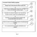
- FIG. 1is a schematic illustration of a method used for the identification or the verification of a person's identity based on bone geometry in accordance with one embodiment of the present invention
- FIG. 2is a schematic illustration of a method used for the building of a normalized template in accordance with the method of FIG. 1 ;
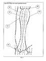
- FIG. 3is a top plan view of a hand of a person showing bones of the hand and acquired points derived from surfaces of the bones in relation to an absolute coordinate system of the hand;
- FIG. 4is a top plan view of the hand of FIG. 3 identifying the bones of the hand;
- FIG. 5is an illustration of a data structure of the points of FIG. 3 .
- FIG. 6is an illustration of a thumb data structure
- FIG. 7is an illustration of a finger data structure
- FIG. 8is an illustration of a hand data structure
- FIG. 9is a top plan view of a bone and acquired points derived from the surface of the bone, showing a base plane of the bone and a local coordinate system of the bone;
- FIG. 10is a top plan view of the hand of FIG. 3 showing local coordinate systems in relation to the absolute coordinate system of the hand;
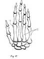
- FIG. 11is a top plan view of a rendered three dimensional model of hand bone geometry in accordance with the normalized template
- FIG. 12is a top plan view of the rendered three dimensional model of FIG. 11 prior to the transformation based on the normalized template.
- FIG. 13is a top plan view of the rendered three dimensional model of FIG. 11 during an intermediate step of the transformation in accordance with the normalized template.
- FIG. 1the steps of a method for producing a model of bone geometry and for identifying or verifying the identity of a person are described below.
- FIG. 1Step 1: “Start Identification”
- a volumetric region comprising bonesis firstly scanned using ultrasound.
- a person or subjectmay place the volumetric region such as a hand on a scanner platen for scanning. Once the subject chooses his/her left or right hand for scanning, at each subsequent identification attempt, the subject must use the same hand that was stored into the record carrier that can be placed on the host or a remote computer.
- the datamay be transmitted and/or searched through an existing network via suitable communication means such as wireless communication for example.
- the handcan be placed in any direction or location within the parameters of the scanner platen because the inventor-created normalization technique transforms scan data to the normalized template, which is then used in the process of comparing and judging whether the scan matches previously stored data in the record carrier.
- the methodis user-friendly and flexible in the sense that the person's hand does not need to be positioned in a fixed place and in a specific alignment to be scanned and processed for comparison.
- this methodmay optionally make use of fixed positioning by means such as an indicator, an indentation or any other suitable means.
- FIG. 1 , Step 2“Hand Bone Geometry Scanner Data Acquisition”
- the hand bone geometry datamay be acquired using a freehand high-resolution ultrasound scanner (not shown).
- the data acquisitionis not limited to any particular method or apparatus for transmitting ultrasonic energy.
- the processinvolves the acquisition of a set of 2D data that represents series of substantially parallel adjacent cross-section planes from throughout the volume of the hand with position data to locate the cross-section planes in space. Combination of these slices creates 3D data structures and images for volumetric data analysis.
- pre-processinga process that may comprise noise reduction and converting reflected ultrasound data from Polar coordinate system to Cartesian coordinate system, and possibly other data processing steps depending on the capabilities of the equipment used
- the acquired scanrepresents the coordinates of 3D points that are derived from the surfaces of the hand bones.
- the coordinates of pointsare defined in relation to the absolute coordinate system (see FIG. 3 , # 14 ) that is predefined by the scanner.
- the suggested methodfor descriptive purposes only, considers that the cross-section planes are orthogonal to Y-axis that is directed (see FIG. 3 ) from the hand base to the tips of the fingers.
- the distance between planesis equal to a pre-set resolution tolerance.
- the sequence processing of datastarts from the tips of the fingers but is not limited to other directions.
- Each cross-section( FIG. 3 , # 12 ) contains points ( FIG. 3 , # 13 ) from the surfaces of all the bones that it runs through.
- FIG. 1Step 3: “Building the Normalized Template of the Hand Bone Set”:
- This stepmay be carried out using the method illustrated in FIG. 2 that is described below in detail.
- the Entity Segregation Algorithmassesses the values of the coordinates of points in relation to the location proximity and attributes the points to the appropriate bone entities.
- the purpose of this step ofis to restructure the retrieved data into a set of entities that identifies all 27 bones of the hand (8 carpal bones ( FIG. 4 , # 17 ), 5 metacarpal bones ( FIG. 4 , # 15 ), and 14 phalanges ( FIG. 4 , # 16 )).
- the 5 metacarpal bones and 14 phalangesare then joined to form the entities known as the fingers.
- pointsare arranged by values of coordinate Y.
- Points with the same coordinate Yare then arranged by values of combinations of coordinates X & Z to form closed sequences defining the current cross-section of the bone surface.
- points of one bone entityare separated from points of other bone entities along the X coordinate.
- the algorithmprocesses the values of coordinates within the pre-defined resolution tolerance and concludes the manner of grouping/segregating bone entities in relation to their location proximity. (i) If the location of two points is within the resolution tolerances, they are grouped in the same bone entity. (ii) If the distance along the X coordinate of the next point in line is greater than the resolution tolerance, it is grouped within the next bone entity. (iii) If the distance along the X coordinate is less than the tolerance, it is further analyzed by Z coordinates to assess the mode of direction. If the current direction is contrary to the previous direction with a steep gradient, then the point is grouped within the next bone entity, otherwise it is grouped in the same bone entity.
- the categorization of a bone entity within a finger elementis conducted.
- the algorithmanalyzes the characteristics of points in terms of size, or area of cross-section of a particular sequence of points.
- a finger bone entityis defined by a set of cross-sections as illustrated in FIG. 5 .
- the algorithmbegins with the largest value of Y coordinates and ends with the smallest value of Y coordinates, and determines the diameter of each cross-section of the bone entity.
- the cross-section with the largest Y coordinatewill define the start of the bone entity.
- Each diameteris then evaluated along the Y coordinate, and is added to the same entity, until the diameter value of the cross-section reaches the pre-defined 0 value.
- This Y coordinatewill define the end of the current entity and the start of a new entity if it exists. This procedure is repeated to separate all the entities in a finger. Segregation of the carpal bones is performed in a similar manner.
- Bone data structureentails: Bone Cross-sections, Bone Integral Parameters, and the Local coordinate system, is illustrated in FIG. 5 .
- Each element of the list of bone cross-sectionsconsists of two members: a number that represent a value of Y coordinate of the cross-section that is common to its points, and a list of X, Z coordinates of all points of the cross-section. The number of points varies for different cross-sections, depending on their size.
- the set of integral parameters of a bonemay contain but is not limited to measurements and calculated values to define the characteristics of a bone as a unit.
- the local coordinate systems of bone entitiesdetermine positions of the entities in relation to other bones that they depend on with an exception of carpal and metacarpal bones that depend only on the absolute coordinate system.
- Thumb and Finger data structures as illustrated in FIG. 6 and FIG. 7entails: Bones, Integral Parameters and the local coordinate system.
- the integral parameters and the local coordinate systemsare represented in the same manner as those in the Bone Data Structure.
- the variance in structureis that the thumb has no middle phalange, whereas the finger consists of Distal, Middle, and Proximal phalanges, and Metacarpal bones.
- the local coordinate systems for the thumb and fingerare coincident with those of the corresponding Metacarpal bones.
- Hand Data Structureand its components are illustrated in FIG. 8 . Its integral parameters define the characteristics of the hand as an entity.
- FIG. 2Step 7: “Define the Local Coordinate System of Each Bone and Finger in Relation to the Absolute Coordinate System”
- the algorithmseeks the two points at the surfaces of the bone entity with the largest distance between them, and sets an imaginary axis ( FIG. 9 , # 18 ) between these two points. If there is more than one set of points that fits the profile of the imaginary axis # 18 , then the line joining the centers of two polygons formed by the ends of such lines would become the imaginary axis.
- the algorithmthen seeks the largest diameter of the bone ( FIG. 9 , # 19 ) that is orthogonal to axis # 18 . It should be noted that if more than one diameter fitting the profile exists, then the method above applies.
- Points # 20 , # 21 a and # 21 b of FIG. 9will define the bone base plane.
- Point # 21 a and # 21 brepresent the diameter # 19 .
- Point # 20represents the end of axis # 18 that is closer to the tip of the hand.
- Point # 22the other end of axis # 18 becomes the origin of the bone local coordinate system with its end preset with rotational angles in relation to the base plane.
- FIG. 10illustrates the local coordinate systems of the bone entities.
- the local coordinate systems of distal phalanges # 23determine positions of the entities in relation to the local coordinate system of the corresponding proximal phalange # 25 of the thumb or of the middle phalange # 24 of other fingers. Further, the local coordinate systems of the middle phalanges # 24 determine positions of the entities in relation to the local coordinate system of the corresponding proximal phalanges # 25 of the finger.
- the local coordinate systems of the proximal phalanges # 25determine positions of the entities in relation to the local coordinate system of the corresponding metacarpal bone # 26 of the finger.
- the local coordinate system of each metacarpal bone and of the corresponding finger entities # 26 , and the local coordinate system of each carpal bone # 27determine positions of the entities in relation to the absolute coordinate system.
- the position of all coordinate systemsare not limited to those that have been shown in FIG. 3 , FIG. 9 , and FIG. 10 .
- FIG. 2 , Step 8“Transform the Coordinates of Points in Each Bone from the Absolute Coordinate System to the Corresponding Local Coordinate System”
- each local coordinate system relating to the absolute coordinate systemis determined by its transformation matrix.
- the vector defining these points in the absolute coordinate systemis multiplied by the inverted transformation matrix.
- Step 9“Determine the Inter-Location Entities in Relation to the Corresponding Entities they Depend on”
- the locationis calculated for entities that belong to the same finger and depend on each other. These inter-locations are compared with the inter-location that has been chosen for a normalized template and the corresponding transformation matrices are formed.
- Step 10“Move all Entities to the Locations Pre-Defined by the Normalized Template”
- the algorithmmoves all bone entities to the locations predefined by a definition of the normalized template as illustrated in FIGS. 11-13 .
- the methodaccounts for possible rotations of distal phalange in relation to the corresponding proximal bone of the thumb or the corresponding middle phalange of other fingers comparing with the pre-defined normalized template inter-locations.
- the algorithmthen accounts for possible rotations of all distal and middle phalanges of all fingers except the thumb in relation to the corresponding proximal phalanges, comparing with the pre-defined normalized template inter-locations.
- the algorithmaccounts for possible rotations of all distal, middle, and proximal phalanges of all fingers (or distal and proximal phalanges for the thumb) in relation to the corresponding metacarpal bones comparing with the pre-defined normalized template inter-locations of these entities.
- the methodaccounts for possible combined rotations of fingers in relation to the corresponding metacarpal bones.
- Step 11“Form a Normalized Set of Coordinates of all Entities to be Compared”
- all the bone entitiesare defined by the cross-sections that were perpendicular to the Y-axis as it was defined in the data set acquired from the scanner. However since acquisition, all bone entities may drift location.
- the algorithmis designed to redefine all points at the surfaces of bone entities accounting for such a drift to place them at the same pre-defined cross-section planes.
- step 3Now the algorithm has finished building of the normalized template (see FIG. 1 , step 3).
- a model of bone geometry of a volumetric region of the bodysuch as a hand can be produced ( FIG. 1 , Steps 1-3).
- the volumetric regionis scanned using ultrasound and geometric data associated with bones within the volumetric region is acquired ( FIG. 1 , Step 2).
- the points of the acquired datamay lie within a plurality of planes or slices extending through the volumetric region. Points derived from at least one surface of the bones is identified from the acquired data.
- the acquired datamay be pre-processed to reduce noise ( FIG. 1 , Step 2).
- the pointsare then organized into separate bone entities representing the bones of the volumetric region ( FIG. 1 , Step 3).
- the pointsare transformed so as to position the bone entities in accordance with a normalized template ( FIG. 1 , Step 3).
- the pointsmay then be stored on a record carrier for future use.
- the transformation of the pointsmay be conducted by firstly defining a local coordinate system for each bone entity in relation to an absolute coordinate system of the volumetric region ( FIG. 2 , Step 7); transforming the points for each bone entity from the absolute coordinate system to their respective local coordinate systems ( FIG. 2 , Step 8); determining relative locations of the bone entities based on a normalized template ( FIG. 2 , Step 9); and transforming the acquired data so as to move the bone entities to their relative locations ( FIG. 2 , Step 10).
- FIG. 11illustrates a three dimensional projection of a model of a hand bone transformed according to the normalized template as it is produced by an Surface Rendering Algorithm.
- This algorithmis optionally used when the new hand bone template is recorded.
- the Surface Rendering Algorithmwas created that forms a surface of the entities approximating it by triangular polygons.
- the algorithmcreates the surface by rendering a sets of polygons to the screen accordingly to the sequence of the points of each couple of adjacent cross-sections.
- the volumetric region to be scannedmay not be positioned exactly at the same position each time it is scanned. Accordingly, the acquired data may have to be transformed in accordance to the normalized template in order to be used to conduct a meaningful comparison with previously acquired geometric models or templates that are stored on a record carrier.
- FIG. 11shows a rendered three dimensional model of hand bone geometry in accordance with a normalized template
- FIG. 12shows a model of acquired hand bone geometry prior to the transformation based on the normalized template.
- FIG. 13shows the model of acquired hand bone geometry during an intermediate step of the transformation ( FIG. 2 , Steps 7-10) in accordance with the normalized template.
- the algorithmmay also calculate integral parameters of the bone geometry. These parameters may include, but are not limited to simple measurements such as length/width of a bone or a group of bones, or some results of calculations such as ratio of length to width or other more complex mathematical processing.
- the algorithmproceeds with a calculation of the fingers integral parameters using the previously calculated bone integral parameters. Next, it calculates the hand integral parameters using the previously calculated bone and finger integral parameters.
- the integral parametersmay be used for comparison purpose as described below.
- the geometric model produced above and/or integral parameters derived from the geometric modelmay be used for comparison with previously acquired and stored geometric models (templates) for the purpose of identifying a person or verifying the identity of a person.
- the identification of a person based on ultrasound scan analysis of bone geometrymay be conducted by firstly scanning a volumetric region such as a hand of the person using ultrasound and acquiring geometric data associated with bones within the volumetric region. Points derived from a surface of the bones may be identified from the acquired data. The points may be organized into separate bone entities representing the bones of the volumetric region and then transformed so as to position the bone entities in accordance with the normalized template. Then, a search may be conducted through previously stored geometric data comprising a plurality of templates, to determine if a match exists between the points of the acquired data and one of the templates. The points of the acquired data may be three-dimensional and lie within a plurality of planes extending through the volumetric region.
- the algorithmsearches in the record carrier for a template that is substantially identical to the obtained normalized template. This process can be accomplished in different ways.
- the determination of whether a match existsmay advantageously be done by comparing an integral parameter of the acquired data with an integral parameter of the previously stored geometric data. Accordingly, in the case of the identification task, the search may be accelerated using the key string built on the base of the integral parameters.
- a personIn case of verification, a person shall present by any means his/her identity information.
- the systemwill retrieve the corresponding template of the person from the record carrier in preparation for the comparison attempt with the identity record. If no such identity record exists, or the identity of the person attempting the verification is falsified, then the verification will be rejected.
- the verification of a person's identity based on ultrasound scan analysis of bone geometrymay be conducted by firstly scanning a volumetric region such as a hand of the person using ultrasound and acquiring geometric data associated with bones within the volumetric region. Points derived from a surface of the bones may be identified from the acquired data. The points may be organized into separate bone entities representing the bones of the volumetric region and then transformed so as to position the bone entities in accordance with the normalized template. The points of the acquired data may then be compared to previously stored geometric data in order to determine if a match exists.
- the previously stored geometric datamay comprise a previously stored template that is retrieved by entering a personal identifier of the person.
- the identifiermay comprises an identification number, name, address or other suitable means of associating a particular template to a person.
- the points of the acquired datamay be three-dimensional and lie within a plurality of planes extending through the volumetric region.
- the comparisonmay be done by determining integral parameters of at least one of the bones from the acquired data and comparing it with a corresponding integral parameter of the template retrieved from the record carrier.
Landscapes
- Health & Medical Sciences (AREA)
- Life Sciences & Earth Sciences (AREA)
- Engineering & Computer Science (AREA)
- Physics & Mathematics (AREA)
- Medical Informatics (AREA)
- Veterinary Medicine (AREA)
- Animal Behavior & Ethology (AREA)
- Surgery (AREA)
- Biophysics (AREA)
- Molecular Biology (AREA)
- Pathology (AREA)
- General Health & Medical Sciences (AREA)
- Biomedical Technology (AREA)
- Heart & Thoracic Surgery (AREA)
- Public Health (AREA)
- Radar, Positioning & Navigation (AREA)
- Remote Sensing (AREA)
- General Physics & Mathematics (AREA)
- Radiology & Medical Imaging (AREA)
- Dentistry (AREA)
- Oral & Maxillofacial Surgery (AREA)
- Acoustics & Sound (AREA)
- Nuclear Medicine, Radiotherapy & Molecular Imaging (AREA)
- Computer Networks & Wireless Communication (AREA)
- Orthopedic Medicine & Surgery (AREA)
- Rheumatology (AREA)
- Human Computer Interaction (AREA)
- Theoretical Computer Science (AREA)
- Multimedia (AREA)
- Ultra Sonic Daignosis Equipment (AREA)
Abstract
Description
- a) scanning the volumetric region using ultrasound and acquiring geometric data associated with bones within the volumetric region;
- b) identifying points from the acquired data that are derived from a surface of the bones;
- c) organizing the points into separate bone entities representing the bones of the volumetric region; and
- d) transforming the points so as to position the bone entities in accordance with a normalized template.
- a) scanning a volumetric region of the person using ultrasound and acquiring geometric data associated with bones within the volumetric region;
- b) identifying points from the acquired data that are derived from a surface of the bones;
- c) organizing the points into separate bone entities representing the bones of the volumetric region;
- d) transforming the points so as to position the bone entities in accordance with a normalized template; and
- e) comparing the points of the acquired data to previously stored geometric data to determine if a match exists.
- a) scanning a volumetric region of the person using ultrasound and acquiring geometric data associated with bones within the volumetric region;
- b) identifying points from the acquired data that are derived from a surface of the bones;
- c) organizing the points into separate bone entities representing the bones of the volumetric region;
- d) transforming the points so as to position the bone entities in accordance with a normalized template; and
- e) searching through previously stored geometric data comprising a plurality of templates, and, determining if a match exists between the points of the acquired data and one of the templates.
Claims (20)
Priority Applications (1)
| Application Number | Priority Date | Filing Date | Title |
|---|---|---|---|
| US12/190,902US7760918B2 (en) | 2003-08-06 | 2008-08-13 | Identification of a person based on ultra-sound scan analyses of hand bone geometry |
Applications Claiming Priority (4)
| Application Number | Priority Date | Filing Date | Title |
|---|---|---|---|
| CA2438220ACA2438220C (en) | 2003-08-06 | 2003-08-06 | Identification of a person based on ultra-sound scan analyses of hand bone geometry |
| CA2438220 | 2003-08-06 | ||
| US10/910,303US7428319B2 (en) | 2003-08-06 | 2004-08-04 | Identification of a person based on ultra-sound scan analyses of hand bone geometry |
| US12/190,902US7760918B2 (en) | 2003-08-06 | 2008-08-13 | Identification of a person based on ultra-sound scan analyses of hand bone geometry |
Related Parent Applications (1)
| Application Number | Title | Priority Date | Filing Date |
|---|---|---|---|
| US10/910,303Continuation-In-PartUS7428319B2 (en) | 2003-08-06 | 2004-08-04 | Identification of a person based on ultra-sound scan analyses of hand bone geometry |
Publications (2)
| Publication Number | Publication Date |
|---|---|
| US20090043202A1 US20090043202A1 (en) | 2009-02-12 |
| US7760918B2true US7760918B2 (en) | 2010-07-20 |
Family
ID=40347193
Family Applications (1)
| Application Number | Title | Priority Date | Filing Date |
|---|---|---|---|
| US12/190,902Expired - LifetimeUS7760918B2 (en) | 2003-08-06 | 2008-08-13 | Identification of a person based on ultra-sound scan analyses of hand bone geometry |
Country Status (1)
| Country | Link |
|---|---|
| US (1) | US7760918B2 (en) |
Cited By (19)
| Publication number | Priority date | Publication date | Assignee | Title |
|---|---|---|---|---|
| US8908894B2 (en) | 2011-12-01 | 2014-12-09 | At&T Intellectual Property I, L.P. | Devices and methods for transferring data through a human body |
| US20160119337A1 (en)* | 2013-03-01 | 2016-04-28 | Paypal, Inc. | Systems and methods for authenticating a user based on a biometric model associated with the user |
| US9349280B2 (en) | 2013-11-18 | 2016-05-24 | At&T Intellectual Property I, L.P. | Disrupting bone conduction signals |
| US9405892B2 (en) | 2013-11-26 | 2016-08-02 | At&T Intellectual Property I, L.P. | Preventing spoofing attacks for bone conduction applications |
| US9430043B1 (en) | 2000-07-06 | 2016-08-30 | At&T Intellectual Property Ii, L.P. | Bioacoustic control system, method and apparatus |
| US9582071B2 (en) | 2014-09-10 | 2017-02-28 | At&T Intellectual Property I, L.P. | Device hold determination using bone conduction |
| US9589482B2 (en) | 2014-09-10 | 2017-03-07 | At&T Intellectual Property I, L.P. | Bone conduction tags |
| US9594433B2 (en) | 2013-11-05 | 2017-03-14 | At&T Intellectual Property I, L.P. | Gesture-based controls via bone conduction |
| US9600079B2 (en) | 2014-10-15 | 2017-03-21 | At&T Intellectual Property I, L.P. | Surface determination via bone conduction |
| US9715774B2 (en) | 2013-11-19 | 2017-07-25 | At&T Intellectual Property I, L.P. | Authenticating a user on behalf of another user based upon a unique body signature determined through bone conduction signals |
| US9882992B2 (en) | 2014-09-10 | 2018-01-30 | At&T Intellectual Property I, L.P. | Data session handoff using bone conduction |
| US10045732B2 (en) | 2014-09-10 | 2018-08-14 | At&T Intellectual Property I, L.P. | Measuring muscle exertion using bone conduction |
| US10108984B2 (en) | 2013-10-29 | 2018-10-23 | At&T Intellectual Property I, L.P. | Detecting body language via bone conduction |
| US10135822B2 (en) | 2017-03-21 | 2018-11-20 | YouaretheID, LLC | Biometric authentication of individuals utilizing characteristics of bone and blood vessel structures |
| US10678322B2 (en) | 2013-11-18 | 2020-06-09 | At&T Intellectual Property I, L.P. | Pressure sensing via bone conduction |
| US10831316B2 (en) | 2018-07-26 | 2020-11-10 | At&T Intellectual Property I, L.P. | Surface interface |
| US10880303B2 (en) | 2017-03-21 | 2020-12-29 | Global E-Dentity, Inc. | Real-time COVID-19 outbreak identification with non-invasive, internal imaging for dual biometric authentication and biometric health monitoring |
| US10913426B2 (en)* | 2016-12-30 | 2021-02-09 | Huawei Technologies Co., Ltd. | Automobile, steering wheel, and driver identity recognition method |
| US11374929B2 (en) | 2017-03-21 | 2022-06-28 | Global E-Dentity, Inc. | Biometric authentication for an augmented reality or a virtual reality device |
Families Citing this family (3)
| Publication number | Priority date | Publication date | Assignee | Title |
|---|---|---|---|---|
| EP2624211A1 (en)* | 2012-02-06 | 2013-08-07 | Samsung Medison Co., Ltd. | Image processing apparatus and method |
| KR102150959B1 (en)* | 2013-05-31 | 2020-09-02 | 삼성메디슨 주식회사 | Method and apparatus for ultrasound diagnosis using 3d volume data |
| CN110930482B (en)* | 2019-11-14 | 2023-10-31 | 北京达佳互联信息技术有限公司 | Method and device for determining bone parameters of human hand, electronic equipment and storage medium |
Citations (48)
| Publication number | Priority date | Publication date | Assignee | Title |
|---|---|---|---|---|
| US3576538A (en) | 1969-04-14 | 1971-04-27 | Identimation Corp | Finger dimension comparison identification system |
| US3576537A (en) | 1968-12-05 | 1971-04-27 | Polaroid Corp | Hand id system |
| US3581282A (en) | 1968-12-03 | 1971-05-25 | Norman G Altman | Palm print identification system |
| US3648240A (en) | 1970-01-15 | 1972-03-07 | Identification Corp | Personnel identification apparatus |
| US3882462A (en) | 1974-01-30 | 1975-05-06 | Sperry Rand Corp | Fingerprint recognition apparatus using non-coherent optical processing |
| US3968476A (en) | 1974-07-17 | 1976-07-06 | Sperry Rand Corporation | Spurious signal removal in optical processor fingerprint identification apparatus |
| US3975711A (en) | 1974-08-30 | 1976-08-17 | Sperry Rand Corporation | Real time fingerprint recording terminal |
| US4032889A (en) | 1976-05-21 | 1977-06-28 | International Business Machines Corporation | Palm print identification |
| US4206441A (en) | 1977-12-23 | 1980-06-03 | Tokyo Shibaura Denki Kabushiki Kaisha | Identification apparatus |
| US4394773A (en) | 1980-07-21 | 1983-07-19 | Siemens Corporation | Fingerprint sensor |
| US4537484A (en) | 1984-01-30 | 1985-08-27 | Identix Incorporated | Fingerprint imaging apparatus |
| US4573193A (en) | 1983-07-25 | 1986-02-25 | Mitsubishi Denki Kabushiki Kaisha | Individual identification apparatus |
| US4720869A (en) | 1986-02-18 | 1988-01-19 | International Business Machines Corporation | Hand dimension verification |
| US4736203A (en) | 1985-07-17 | 1988-04-05 | Recognition Systems, Inc. | 3D hand profile identification apparatus |
| US4792226A (en) | 1987-02-27 | 1988-12-20 | C.F.A. Technologies, Inc. | Optical fingerprinting system |
| US4857916A (en) | 1987-02-26 | 1989-08-15 | Bellin Robert W | System and method for identifying an individual utilizing grasping pressures |
| US4977601A (en) | 1986-03-27 | 1990-12-11 | Werner Pritzl | Method of recognizing a fingerprint |
| US5045940A (en) | 1989-12-22 | 1991-09-03 | Avid Technology, Inc. | Video/audio transmission systsem and method |
| US5073950A (en) | 1989-04-13 | 1991-12-17 | Personnel Identification & Entry Access Control, Inc. | Finger profile identification system |
| US5131038A (en) | 1990-11-07 | 1992-07-14 | Motorola, Inc. | Portable authentification system |
| US5325442A (en) | 1990-05-18 | 1994-06-28 | U.S. Philips Corporation | Fingerprint sensing device and recognition system having predetermined electrode activation |
| US5335288A (en) | 1992-02-10 | 1994-08-02 | Faulkner Keith W | Apparatus and method for biometric identification |
| US5515298A (en) | 1993-03-30 | 1996-05-07 | Sonident Anstalt Liechtensteinischen Rechts | Apparatus for determining surface structures |
| US5647364A (en) | 1995-02-15 | 1997-07-15 | Ultra-Scan Corporation | Ultrasonic biometric imaging and identity verification system |
| US5719950A (en) | 1994-03-24 | 1998-02-17 | Minnesota Mining And Manufacturing Company | Biometric, personal authentication system |
| US5737439A (en) | 1996-10-29 | 1998-04-07 | Smarttouch, Llc. | Anti-fraud biometric scanner that accurately detects blood flow |
| US5787187A (en) | 1996-04-01 | 1998-07-28 | Sandia Corporation | Systems and methods for biometric identification using the acoustic properties of the ear canal |
| US5793881A (en) | 1995-08-31 | 1998-08-11 | Stiver; John A. | Identification system |
| US5892838A (en) | 1996-06-11 | 1999-04-06 | Minnesota Mining And Manufacturing Company | Biometric recognition using a classification neural network |
| CA2308381A1 (en) | 1997-11-20 | 1999-06-03 | Quo Technologies, L.L.C. | Method and system for biometric recognition using unique internal distinguishing characteristics |
| US6092192A (en) | 1998-01-16 | 2000-07-18 | International Business Machines Corporation | Apparatus and methods for providing repetitive enrollment in a plurality of biometric recognition systems based on an initial enrollment |
| US6219639B1 (en) | 1998-04-28 | 2001-04-17 | International Business Machines Corporation | Method and apparatus for recognizing identity of individuals employing synchronized biometrics |
| US6219439B1 (en) | 1998-07-09 | 2001-04-17 | Paul M. Burger | Biometric authentication system |
| US6336045B1 (en) | 1998-09-11 | 2002-01-01 | Quid Technologies | Measurement of electric and/or magnetic properties in organisms using induced currents |
| US6343140B1 (en) | 1998-09-11 | 2002-01-29 | Quid Technologies Llc | Method and apparatus for shooting using biometric recognition |
| US20020053857A1 (en) | 2000-03-23 | 2002-05-09 | Scott Walter G. | Piezoelectric identification device and applications thereof |
| US6421453B1 (en) | 1998-05-15 | 2002-07-16 | International Business Machines Corporation | Apparatus and methods for user recognition employing behavioral passwords |
| US20020162031A1 (en) | 2001-03-08 | 2002-10-31 | Shmuel Levin | Method and apparatus for automatic control of access |
| US6483929B1 (en) | 2000-06-08 | 2002-11-19 | Tarian Llc | Method and apparatus for histological and physiological biometric operation and authentication |
| US20030001459A1 (en) | 2000-03-23 | 2003-01-02 | Cross Match Technologies, Inc. | Secure wireless sales transaction using print information to verify a purchaser's identity |
| US6507662B1 (en) | 1998-09-11 | 2003-01-14 | Quid Technologies Llc | Method and system for biometric recognition based on electric and/or magnetic properties |
| US20030133596A1 (en) | 1998-09-11 | 2003-07-17 | Brooks Juliana H. J. | Method and system for detecting acoustic energy representing electric and/or magnetic properties |
| US6628810B1 (en) | 1997-03-13 | 2003-09-30 | Koninklijke Philips Electronics N.V. | Hand biometrics sensing device |
| US6724689B2 (en) | 2002-03-08 | 2004-04-20 | Philip Koenig | Personal identification method and apparatus using acoustic resonance analysis of body parts |
| US6862253B2 (en) | 2002-10-23 | 2005-03-01 | Robert L. Blosser | Sonic identification system and method |
| US7190817B1 (en) | 1999-09-10 | 2007-03-13 | Ultra-Scan Corporation | Mobile fingerprint scanner and docking station |
| US7236616B1 (en) | 1999-08-09 | 2007-06-26 | Cross Match Technologies, Inc. | Biometric piezo scanner |
| US7254255B2 (en) | 2002-04-12 | 2007-08-07 | Stmicroelectronics Ltd. | Biometric sensor apparatus and methods |
- 2008
- 2008-08-13USUS12/190,902patent/US7760918B2/ennot_activeExpired - Lifetime
Patent Citations (55)
| Publication number | Priority date | Publication date | Assignee | Title |
|---|---|---|---|---|
| US3581282A (en) | 1968-12-03 | 1971-05-25 | Norman G Altman | Palm print identification system |
| US3576537A (en) | 1968-12-05 | 1971-04-27 | Polaroid Corp | Hand id system |
| US3576538A (en) | 1969-04-14 | 1971-04-27 | Identimation Corp | Finger dimension comparison identification system |
| US3648240A (en) | 1970-01-15 | 1972-03-07 | Identification Corp | Personnel identification apparatus |
| US3882462A (en) | 1974-01-30 | 1975-05-06 | Sperry Rand Corp | Fingerprint recognition apparatus using non-coherent optical processing |
| US3968476A (en) | 1974-07-17 | 1976-07-06 | Sperry Rand Corporation | Spurious signal removal in optical processor fingerprint identification apparatus |
| US3975711A (en) | 1974-08-30 | 1976-08-17 | Sperry Rand Corporation | Real time fingerprint recording terminal |
| US4032889A (en) | 1976-05-21 | 1977-06-28 | International Business Machines Corporation | Palm print identification |
| US4206441A (en) | 1977-12-23 | 1980-06-03 | Tokyo Shibaura Denki Kabushiki Kaisha | Identification apparatus |
| US4394773A (en) | 1980-07-21 | 1983-07-19 | Siemens Corporation | Fingerprint sensor |
| US4573193A (en) | 1983-07-25 | 1986-02-25 | Mitsubishi Denki Kabushiki Kaisha | Individual identification apparatus |
| US4537484A (en) | 1984-01-30 | 1985-08-27 | Identix Incorporated | Fingerprint imaging apparatus |
| US4736203A (en) | 1985-07-17 | 1988-04-05 | Recognition Systems, Inc. | 3D hand profile identification apparatus |
| US4720869A (en) | 1986-02-18 | 1988-01-19 | International Business Machines Corporation | Hand dimension verification |
| US4977601A (en) | 1986-03-27 | 1990-12-11 | Werner Pritzl | Method of recognizing a fingerprint |
| US4857916A (en) | 1987-02-26 | 1989-08-15 | Bellin Robert W | System and method for identifying an individual utilizing grasping pressures |
| US4792226A (en) | 1987-02-27 | 1988-12-20 | C.F.A. Technologies, Inc. | Optical fingerprinting system |
| US5073950A (en) | 1989-04-13 | 1991-12-17 | Personnel Identification & Entry Access Control, Inc. | Finger profile identification system |
| US5045940A (en) | 1989-12-22 | 1991-09-03 | Avid Technology, Inc. | Video/audio transmission systsem and method |
| US5325442A (en) | 1990-05-18 | 1994-06-28 | U.S. Philips Corporation | Fingerprint sensing device and recognition system having predetermined electrode activation |
| US5131038A (en) | 1990-11-07 | 1992-07-14 | Motorola, Inc. | Portable authentification system |
| US5335288A (en) | 1992-02-10 | 1994-08-02 | Faulkner Keith W | Apparatus and method for biometric identification |
| US5483601A (en) | 1992-02-10 | 1996-01-09 | Keith Faulkner | Apparatus and method for biometric identification using silhouette and displacement images of a portion of a person's hand |
| US5515298A (en) | 1993-03-30 | 1996-05-07 | Sonident Anstalt Liechtensteinischen Rechts | Apparatus for determining surface structures |
| US5719950A (en) | 1994-03-24 | 1998-02-17 | Minnesota Mining And Manufacturing Company | Biometric, personal authentication system |
| US5647364A (en) | 1995-02-15 | 1997-07-15 | Ultra-Scan Corporation | Ultrasonic biometric imaging and identity verification system |
| US6296610B1 (en) | 1995-02-15 | 2001-10-02 | Ultra-Scan Corporation | Ultrasonic biometric imaging and identity verification system |
| US5935071A (en) | 1995-02-15 | 1999-08-10 | Ultra-Scan Corporation | Ultrasonic biometric imaging and identity verification system |
| US5793881A (en) | 1995-08-31 | 1998-08-11 | Stiver; John A. | Identification system |
| US5787187A (en) | 1996-04-01 | 1998-07-28 | Sandia Corporation | Systems and methods for biometric identification using the acoustic properties of the ear canal |
| US5892838A (en) | 1996-06-11 | 1999-04-06 | Minnesota Mining And Manufacturing Company | Biometric recognition using a classification neural network |
| US5737439A (en) | 1996-10-29 | 1998-04-07 | Smarttouch, Llc. | Anti-fraud biometric scanner that accurately detects blood flow |
| US6628810B1 (en) | 1997-03-13 | 2003-09-30 | Koninklijke Philips Electronics N.V. | Hand biometrics sensing device |
| CA2308381A1 (en) | 1997-11-20 | 1999-06-03 | Quo Technologies, L.L.C. | Method and system for biometric recognition using unique internal distinguishing characteristics |
| US6092192A (en) | 1998-01-16 | 2000-07-18 | International Business Machines Corporation | Apparatus and methods for providing repetitive enrollment in a plurality of biometric recognition systems based on an initial enrollment |
| US6219639B1 (en) | 1998-04-28 | 2001-04-17 | International Business Machines Corporation | Method and apparatus for recognizing identity of individuals employing synchronized biometrics |
| US6421453B1 (en) | 1998-05-15 | 2002-07-16 | International Business Machines Corporation | Apparatus and methods for user recognition employing behavioral passwords |
| US6219439B1 (en) | 1998-07-09 | 2001-04-17 | Paul M. Burger | Biometric authentication system |
| US6343140B1 (en) | 1998-09-11 | 2002-01-29 | Quid Technologies Llc | Method and apparatus for shooting using biometric recognition |
| US6336045B1 (en) | 1998-09-11 | 2002-01-01 | Quid Technologies | Measurement of electric and/or magnetic properties in organisms using induced currents |
| US6898299B1 (en) | 1998-09-11 | 2005-05-24 | Juliana H. J. Brooks | Method and system for biometric recognition based on electric and/or magnetic characteristics |
| US6507662B1 (en) | 1998-09-11 | 2003-01-14 | Quid Technologies Llc | Method and system for biometric recognition based on electric and/or magnetic properties |
| US20030133596A1 (en) | 1998-09-11 | 2003-07-17 | Brooks Juliana H. J. | Method and system for detecting acoustic energy representing electric and/or magnetic properties |
| US7236616B1 (en) | 1999-08-09 | 2007-06-26 | Cross Match Technologies, Inc. | Biometric piezo scanner |
| US7190817B1 (en) | 1999-09-10 | 2007-03-13 | Ultra-Scan Corporation | Mobile fingerprint scanner and docking station |
| US20030001459A1 (en) | 2000-03-23 | 2003-01-02 | Cross Match Technologies, Inc. | Secure wireless sales transaction using print information to verify a purchaser's identity |
| US6720712B2 (en) | 2000-03-23 | 2004-04-13 | Cross Match Technologies, Inc. | Piezoelectric identification device and applications thereof |
| US6844660B2 (en) | 2000-03-23 | 2005-01-18 | Cross Match Technologies, Inc. | Method for obtaining biometric data for an individual in a secure transaction |
| US20020053857A1 (en) | 2000-03-23 | 2002-05-09 | Scott Walter G. | Piezoelectric identification device and applications thereof |
| US6483929B1 (en) | 2000-06-08 | 2002-11-19 | Tarian Llc | Method and apparatus for histological and physiological biometric operation and authentication |
| US20040088553A1 (en) | 2001-03-08 | 2004-05-06 | Shmuel Levin | Method and apparatus for automatic control of access |
| US20020162031A1 (en) | 2001-03-08 | 2002-10-31 | Shmuel Levin | Method and apparatus for automatic control of access |
| US6724689B2 (en) | 2002-03-08 | 2004-04-20 | Philip Koenig | Personal identification method and apparatus using acoustic resonance analysis of body parts |
| US7254255B2 (en) | 2002-04-12 | 2007-08-07 | Stmicroelectronics Ltd. | Biometric sensor apparatus and methods |
| US6862253B2 (en) | 2002-10-23 | 2005-03-01 | Robert L. Blosser | Sonic identification system and method |
Non-Patent Citations (8)
| Title |
|---|
| Department of Computer Science, Hong Kong University of Science and Technology, HongKong, 2003, 8 p. |
| R. D. Danese, A.A. Licata, "Ultrasound of the Skeleton: Review of its Clinical Applications and Pitfalls," "Current Rheumatology Reports," 2001, vol. 3, pp. 245-248. |
| S. A. Teefey, W.D. Middleton, M. I. Boyer, "Sonography of the Hand and Wrist," "Seminars Ultrasound, CT, and MRI," 2000, 21(3). pp. 192-204. |
| S. Bianchi, C. Martinoli, D. Sureda and G. Rizzatto, "Ultrasound of the Hand," "European Journal of Ultrasound," 2001, vol. 14, No. 1, pp. 29-34. |
| Skokowski Can Biometric Defeat Terror?, Stanford University, pp. 1-12, Feb. 2002. |
| T. Kahana, J. Hiss, "Positive Identification by Means of Trabecular Bone Pattern Identification," "Journal of Forensic Sciences," 1994, vol. 39, No. 5, pp. 1325-1330. |
| T. Kahana, J. Hiss, P. Smith, "Quantitative Assessment of Trabecular Bone Pattern Identification," "Journal of Forensic Sciences," 1998, vol. 39, No. 5, pp. 1144-1147. |
| Vitria "Sistemed Biometrics", pp. 1-23, 1999. |
Cited By (38)
| Publication number | Priority date | Publication date | Assignee | Title |
|---|---|---|---|---|
| US9430043B1 (en) | 2000-07-06 | 2016-08-30 | At&T Intellectual Property Ii, L.P. | Bioacoustic control system, method and apparatus |
| US10126828B2 (en) | 2000-07-06 | 2018-11-13 | At&T Intellectual Property Ii, L.P. | Bioacoustic control system, method and apparatus |
| US9712929B2 (en) | 2011-12-01 | 2017-07-18 | At&T Intellectual Property I, L.P. | Devices and methods for transferring data through a human body |
| US8908894B2 (en) | 2011-12-01 | 2014-12-09 | At&T Intellectual Property I, L.P. | Devices and methods for transferring data through a human body |
| US20160119337A1 (en)* | 2013-03-01 | 2016-04-28 | Paypal, Inc. | Systems and methods for authenticating a user based on a biometric model associated with the user |
| US10666648B2 (en) | 2013-03-01 | 2020-05-26 | Paypal, Inc. | Systems and methods for authenticating a user based on a biometric model associated with the user |
| US11863554B2 (en) | 2013-03-01 | 2024-01-02 | Paypal, Inc. | Systems and methods for authenticating a user based on a biometric model associated with the user |
| US11349835B2 (en) | 2013-03-01 | 2022-05-31 | Paypal, Inc. | Systems and methods for authenticating a user based on a biometric model associated with the user |
| US9832191B2 (en)* | 2013-03-01 | 2017-11-28 | Paypal, Inc. | Systems and methods for authenticating a user based on a biometric model associated with the user |
| US10108984B2 (en) | 2013-10-29 | 2018-10-23 | At&T Intellectual Property I, L.P. | Detecting body language via bone conduction |
| US9594433B2 (en) | 2013-11-05 | 2017-03-14 | At&T Intellectual Property I, L.P. | Gesture-based controls via bone conduction |
| US10831282B2 (en) | 2013-11-05 | 2020-11-10 | At&T Intellectual Property I, L.P. | Gesture-based controls via bone conduction |
| US10281991B2 (en) | 2013-11-05 | 2019-05-07 | At&T Intellectual Property I, L.P. | Gesture-based controls via bone conduction |
| US10964204B2 (en) | 2013-11-18 | 2021-03-30 | At&T Intellectual Property I, L.P. | Disrupting bone conduction signals |
| US9997060B2 (en) | 2013-11-18 | 2018-06-12 | At&T Intellectual Property I, L.P. | Disrupting bone conduction signals |
| US10678322B2 (en) | 2013-11-18 | 2020-06-09 | At&T Intellectual Property I, L.P. | Pressure sensing via bone conduction |
| US9349280B2 (en) | 2013-11-18 | 2016-05-24 | At&T Intellectual Property I, L.P. | Disrupting bone conduction signals |
| US10497253B2 (en) | 2013-11-18 | 2019-12-03 | At&T Intellectual Property I, L.P. | Disrupting bone conduction signals |
| US9715774B2 (en) | 2013-11-19 | 2017-07-25 | At&T Intellectual Property I, L.P. | Authenticating a user on behalf of another user based upon a unique body signature determined through bone conduction signals |
| US9972145B2 (en)* | 2013-11-19 | 2018-05-15 | At&T Intellectual Property I, L.P. | Authenticating a user on behalf of another user based upon a unique body signature determined through bone conduction signals |
| US9736180B2 (en) | 2013-11-26 | 2017-08-15 | At&T Intellectual Property I, L.P. | Preventing spoofing attacks for bone conduction applications |
| US9405892B2 (en) | 2013-11-26 | 2016-08-02 | At&T Intellectual Property I, L.P. | Preventing spoofing attacks for bone conduction applications |
| US10276003B2 (en) | 2014-09-10 | 2019-04-30 | At&T Intellectual Property I, L.P. | Bone conduction tags |
| US9582071B2 (en) | 2014-09-10 | 2017-02-28 | At&T Intellectual Property I, L.P. | Device hold determination using bone conduction |
| US9589482B2 (en) | 2014-09-10 | 2017-03-07 | At&T Intellectual Property I, L.P. | Bone conduction tags |
| US10045732B2 (en) | 2014-09-10 | 2018-08-14 | At&T Intellectual Property I, L.P. | Measuring muscle exertion using bone conduction |
| US11096622B2 (en) | 2014-09-10 | 2021-08-24 | At&T Intellectual Property I, L.P. | Measuring muscle exertion using bone conduction |
| US9882992B2 (en) | 2014-09-10 | 2018-01-30 | At&T Intellectual Property I, L.P. | Data session handoff using bone conduction |
| US9600079B2 (en) | 2014-10-15 | 2017-03-21 | At&T Intellectual Property I, L.P. | Surface determination via bone conduction |
| US10913426B2 (en)* | 2016-12-30 | 2021-02-09 | Huawei Technologies Co., Ltd. | Automobile, steering wheel, and driver identity recognition method |
| US10880303B2 (en) | 2017-03-21 | 2020-12-29 | Global E-Dentity, Inc. | Real-time COVID-19 outbreak identification with non-invasive, internal imaging for dual biometric authentication and biometric health monitoring |
| US10721228B2 (en) | 2017-03-21 | 2020-07-21 | Global E-Dentity Inc. | Biometric authentication of individuals utilizing characteristics of bone and blood vessel structures |
| US11277405B2 (en) | 2017-03-21 | 2022-03-15 | Global E-Dentity, Inc. | Dual biometric authentication and biometric health monitoring using chemosensory and internal imaging data |
| US10135822B2 (en) | 2017-03-21 | 2018-11-20 | YouaretheID, LLC | Biometric authentication of individuals utilizing characteristics of bone and blood vessel structures |
| US11368455B2 (en) | 2017-03-21 | 2022-06-21 | Global E-Dentity, Inc. | Biometric authentication of individuals utilizing characteristics of bone and blood vessel structures |
| US11374929B2 (en) | 2017-03-21 | 2022-06-28 | Global E-Dentity, Inc. | Biometric authentication for an augmented reality or a virtual reality device |
| US10547611B2 (en) | 2017-03-21 | 2020-01-28 | YouaretheID, LLC | Biometric authentication of individuals utilizing characteristics of bone and blood vessel structures |
| US10831316B2 (en) | 2018-07-26 | 2020-11-10 | At&T Intellectual Property I, L.P. | Surface interface |
Also Published As
| Publication number | Publication date |
|---|---|
| US20090043202A1 (en) | 2009-02-12 |
Similar Documents
| Publication | Publication Date | Title |
|---|---|---|
| US7760918B2 (en) | Identification of a person based on ultra-sound scan analyses of hand bone geometry | |
| EP1835443B1 (en) | Biometric authentication method and biometric authentication apparatus | |
| US7242807B2 (en) | Imaging of biometric information based on three-dimensional shapes | |
| US7822237B2 (en) | Image matching apparatus, image matching method, and image matching program | |
| JP3975248B2 (en) | Biometric recognition using neural network classification | |
| US6487306B1 (en) | System and method for deriving a string-based representation of a fingerprint image | |
| US6947579B2 (en) | Three-dimensional face recognition | |
| US6185318B1 (en) | System and method for matching (fingerprint) images an aligned string-based representation | |
| JP3558025B2 (en) | Personal authentication device and method | |
| WO2007050187A2 (en) | Method and system for detecting biometric liveness | |
| Puhan et al. | Efficient segmentation technique for noisy frontal view iris images using Fourier spectral density | |
| US20040240711A1 (en) | Face identification verification using 3 dimensional modeling | |
| EP1956557A1 (en) | Generating a 3-D representation form | |
| WO2018213856A2 (en) | Digital data minutiae processing for the analysis of cultural artefacts | |
| US7428319B2 (en) | Identification of a person based on ultra-sound scan analyses of hand bone geometry | |
| JP4426029B2 (en) | Image collation method and apparatus | |
| Nurre et al. | On segmenting the three-dimensional scan data of a human body | |
| CN109815359A (en) | Image retrieval method and related products | |
| JP4760422B2 (en) | Biometric identification device | |
| JP2004178606A (en) | Personal authentication device and method | |
| US20170372124A1 (en) | Unobtrusive identity matcher: a tool for real-time verification of identity | |
| JP2002175529A (en) | Personal identification device | |
| JP2004102993A (en) | Personal authentication device and method | |
| Iula et al. | Palmprint recognition based on ultrasound imaging | |
| KR100696251B1 (en) | Setting method of comparison area for iris recognition and generating user authentication information and device |
Legal Events
| Date | Code | Title | Description |
|---|---|---|---|
| AS | Assignment | Owner name:CLICK-INTO INC.,CANADA Free format text:NUNC PRO TUNC ASSIGNMENT;ASSIGNORS:BEZVERSHENKO, ZINAYIDA;TCHOUIKEVITCH, VOLODYMYR;GHORAYEB, JOHN;SIGNING DATES FROM 20100608 TO 20100616;REEL/FRAME:024599/0405 Owner name:BEZVERSHENKO, ZINAYIDA,CANADA Free format text:NUNC PRO TUNC ASSIGNMENT;ASSIGNORS:BEZVERSHENKO, ZINAYIDA;TCHOUIKEVITCH, VOLODYMYR;GHORAYEB, JOHN;SIGNING DATES FROM 20100608 TO 20100616;REEL/FRAME:024599/0405 Owner name:TCHOUIKEVITCH, VOLODYMYR,CANADA Free format text:NUNC PRO TUNC ASSIGNMENT;ASSIGNORS:BEZVERSHENKO, ZINAYIDA;TCHOUIKEVITCH, VOLODYMYR;GHORAYEB, JOHN;SIGNING DATES FROM 20100608 TO 20100616;REEL/FRAME:024599/0405 Owner name:GHORAYEB, JOHN,CANADA Free format text:NUNC PRO TUNC ASSIGNMENT;ASSIGNORS:BEZVERSHENKO, ZINAYIDA;TCHOUIKEVITCH, VOLODYMYR;GHORAYEB, JOHN;SIGNING DATES FROM 20100608 TO 20100616;REEL/FRAME:024599/0405 Owner name:CLICK-INTO INC., CANADA Free format text:NUNC PRO TUNC ASSIGNMENT;ASSIGNORS:BEZVERSHENKO, ZINAYIDA;TCHOUIKEVITCH, VOLODYMYR;GHORAYEB, JOHN;SIGNING DATES FROM 20100608 TO 20100616;REEL/FRAME:024599/0405 Owner name:BEZVERSHENKO, ZINAYIDA, CANADA Free format text:NUNC PRO TUNC ASSIGNMENT;ASSIGNORS:BEZVERSHENKO, ZINAYIDA;TCHOUIKEVITCH, VOLODYMYR;GHORAYEB, JOHN;SIGNING DATES FROM 20100608 TO 20100616;REEL/FRAME:024599/0405 Owner name:TCHOUIKEVITCH, VOLODYMYR, CANADA Free format text:NUNC PRO TUNC ASSIGNMENT;ASSIGNORS:BEZVERSHENKO, ZINAYIDA;TCHOUIKEVITCH, VOLODYMYR;GHORAYEB, JOHN;SIGNING DATES FROM 20100608 TO 20100616;REEL/FRAME:024599/0405 Owner name:GHORAYEB, JOHN, CANADA Free format text:NUNC PRO TUNC ASSIGNMENT;ASSIGNORS:BEZVERSHENKO, ZINAYIDA;TCHOUIKEVITCH, VOLODYMYR;GHORAYEB, JOHN;SIGNING DATES FROM 20100608 TO 20100616;REEL/FRAME:024599/0405 | |
| STCF | Information on status: patent grant | Free format text:PATENTED CASE | |
| FPAY | Fee payment | Year of fee payment:4 | |
| MAFP | Maintenance fee payment | Free format text:PAYMENT OF MAINTENANCE FEE, 8TH YR, SMALL ENTITY (ORIGINAL EVENT CODE: M2552) Year of fee payment:8 | |
| MAFP | Maintenance fee payment | Free format text:PAYMENT OF MAINTENANCE FEE, 12TH YR, SMALL ENTITY (ORIGINAL EVENT CODE: M2553); ENTITY STATUS OF PATENT OWNER: SMALL ENTITY Year of fee payment:12 |