US7760898B2 - Eyeglasses with hearing enhanced and other audio signal-generating capabilities - Google Patents
Eyeglasses with hearing enhanced and other audio signal-generating capabilitiesDownload PDFInfo
- Publication number
- US7760898B2 US7760898B2US11/183,262US18326205AUS7760898B2US 7760898 B2US7760898 B2US 7760898B2US 18326205 AUS18326205 AUS 18326205AUS 7760898 B2US7760898 B2US 7760898B2
- Authority
- US
- United States
- Prior art keywords
- glasses
- audio signals
- user
- frame
- hearing
- Prior art date
- Legal status (The legal status is an assumption and is not a legal conclusion. Google has not performed a legal analysis and makes no representation as to the accuracy of the status listed.)
- Expired - Fee Related, expires
Links
Images


Classifications
- G—PHYSICS
- G02—OPTICS
- G02C—SPECTACLES; SUNGLASSES OR GOGGLES INSOFAR AS THEY HAVE THE SAME FEATURES AS SPECTACLES; CONTACT LENSES
- G02C5/00—Constructions of non-optical parts
- G02C5/001—Constructions of non-optical parts specially adapted for particular purposes, not otherwise provided for or not fully classifiable according to technical characteristics, e.g. therapeutic glasses
- G—PHYSICS
- G02—OPTICS
- G02C—SPECTACLES; SUNGLASSES OR GOGGLES INSOFAR AS THEY HAVE THE SAME FEATURES AS SPECTACLES; CONTACT LENSES
- G02C11/00—Non-optical adjuncts; Attachment thereof
- G02C11/06—Hearing aids
- G—PHYSICS
- G02—OPTICS
- G02C—SPECTACLES; SUNGLASSES OR GOGGLES INSOFAR AS THEY HAVE THE SAME FEATURES AS SPECTACLES; CONTACT LENSES
- G02C11/00—Non-optical adjuncts; Attachment thereof
- G02C11/10—Electronic devices other than hearing aids
- H—ELECTRICITY
- H04—ELECTRIC COMMUNICATION TECHNIQUE
- H04R—LOUDSPEAKERS, MICROPHONES, GRAMOPHONE PICK-UPS OR LIKE ACOUSTIC ELECTROMECHANICAL TRANSDUCERS; DEAF-AID SETS; PUBLIC ADDRESS SYSTEMS
- H04R5/00—Stereophonic arrangements
- H04R5/033—Headphones for stereophonic communication
- H04R5/0335—Earpiece support, e.g. headbands or neckrests
Definitions
- the present inventionrelates generally to glasses and more particularly to eyeglasses with hearing-enhanced capabilities.
- a significant portion of our populationhas a certain degree of hearing loss. This can be due to, for example, heredity, noise exposure or simply aging.
- Hearing aidshave been the traditional approach for those with hearing difficulties. However, just in the United States, out of the 26 to 28 million people who are hearing impaired, only about 20% of them actually wear any hearing aids. Further, this number of hearing impaired is steadily increasing. Hearing loss typically goes with aging. With the baby boom population rapidly aging, the median age of the entire population is going up. Significantly more people will be in need of hearing aids.
- BTEbehind-the-ear
- ITEin-the-ear
- CICcompletely-in-the-canal
- the BTE hearing aidshave a number of advantages. They are more applicable for those with severe hearing loss. Through the use of venting, they reduce to a certain degree the effects of occlusion, which is the hollowness, echoic or stuffed sensation of hearing one's own voice as one talks with a hearing aid inside one's ear.
- ITEor CIC
- Hearing abilitytends to decrease gradually, particularly as we age.
- a person with mildly-impaired hearingnormally does not need the same degree of hearing assistance as one with severely-impaired hearing. Nevertheless, though their hearing loss is not severe, they still could benefit from mild or moderate enhancement to their hearing.
- the present inventionprovides different embodiments of glasses that can be applied to multiple functions. With a user wearing such a pair of glasses, it would be more difficult for a third party to know the specific function or reason the user is wearing the glasses for. Regarding the locations of the electrical components for the multiple functions, different embodiments range from all of the components in the glasses to the glasses primarily functioning as a headset.
- the present inventionpertains to a pair of glasses with hearing enhancement and other signal generating capabilities.
- Most people todaydo not desire to wear hearing aids or hearing enhancement devices. One major reason could be that they do not want to be perceived as being old.
- a pair of glasses, with speakershas hearing enhancement capabilities. With the speakers in the glasses, the speakers can be positioned in close proximity to the ears of the users.
- the glassesalso include at least one electrical component to generate other audio signals. For example, the glasses can play music. Such a hearing-enhanced device can remove the associated stigma of conventional hearing aids.
- a third partymay not be able to tell whether the user is wearing the glasses to hear music or whether the user is wearing the glasses to have his hearing enhanced.
- the glassesinclude at least one speaker and typically two. Each speaker is in one of the temples of the glasses, closer to the corresponding hinge of that temple than the other end (the free end) of the temple. There is also a tube extending from the speaker to guide sound generated by the speaker to the corresponding ear of the user. The tube can be rotated, such as from behind the temple to being downward at an angle towards the ear of the user.
- the two speakerscan also be electrically connected by a conductor, with the conductor linking the speakers through the lens holders of the glasses.
- the glassesinclude a microphone, which can be located close to one of the hinges of the glasses. In another embodiment, there can be two microphones. The one or more microphones can be directional for receiving signals in specific directions.
- some of the hearing enhanced electronicsare not in the glasses. Instead they are in a portable device carried by the user.
- the portable deviceis electronically coupled to the glasses wirelessly or through a wired connection.
- the glassesalso include a wireless transceiver.
- the microphonedoes not have to be at the glasses.
- the microphonecan also be wirelessly coupled to the glasses and/or the portable device.
- the glassesalso include a connector for at least one wire to be connected to the glasses.
- the connectorcan be at the free end of one of the temples of the glasses, or the connector can be at another location at the glasses. Different types of standard or non-standard connectors can be used.
- the microphonealso does not have to be at the glasses.
- the microphonecan be mounted on the wire that connects the glasses to the portable device.
- the glassescan have a number of hearing enhancing capabilities.
- the hearing enhancementis for those with mild or medium hearing loss. In another embodiment, the hearing enhancement is for those with severe hearing loss.
- One hearing enhancement functionalityis frequency-dependent amplification. For example, higher frequencies are amplified more than lower frequencies; certain frequency bands are not amplified; or the frequencies to be amplified are tailored to the user.
- hearing enhancement capabilitiescan be calibrated against the user.
- the calibrationcan be done by the user or by a third party.
- the calibrationcan be performed through a website, which guides the user through the process.
- the calibrated frequency hearing profile of the usercan be stored. Such calibration can be performed periodically, such as once a year.
- the glassesmay also include at least one electrical component for power management.
- Hearing enhancementdoes not have to be fully functional at all times.
- the hearing enhancement functionis on demand.
- the enhancementcan go into a sleep mode when there is no audio fluctuation beyond a certain threshold in the ambient environment.
- the amplificationcan also depend on the ambient noise level.
- the glassescan also have at least one electrical component to generate other audio signals. These other audio signals do not originate from signals captured by the microphone(s) in the glasses. These signals can originate from relatively private sources or public sources.
- the glassesinclude the electrical components to operate as a phone.
- the glassescan pick up signals from a caller, and the speaker(s) in the glasses re-generate the audio signals of the caller.
- some of the electrical components of the phonecan be in a portable device wired or wirelessly coupled to the glasses.
- the indicatorcould be a signal light.
- the hearing enhancement modeif the user wants to pick up the incoming call, the hearing enhancement mode is deactivated. In another embodiment, one or more functionalities of the hearing enhancement mode operate on the incoming call. There can also be noise cancellation functionalities, such as through two directional microphones, one pointing at the user's mouth, and the other pointing away.
- the glassesinclude the electrical components to operate as a player. Again some of the electrical components of the player can be in a portable device wired or wirelessly coupled to the glasses.
- the playercan be a MP3 or other multimedia asset player.
- the playercan be a radio.
- the radiocan be personalized to the user, for example, by being aware of the songs the user prefers.
- the hearing enhancement modeis deactivated.
- different capabilities of the hearing enhancement modeoperate on the signals from the player.
- the other audio signalsare from public sources.
- the glassescan be coupled to a conference microphone or a theater speaker wirelessly, and thus be capable of capturing and enhancing the signals from those sources.
- the couplingcan be through a portable device wired or wirelessly coupled to the glasses.
- control knobs or switchesat the glasses or at a portable device coupled to the glasses. Different types of switches are applicable for different applications.
- the power sourcessuch as batteries
- the power sourcesare in the glasses.
- the power sourcesare located outside the glasses, but connected to the glasses through an adapter.
- the power sourcesare in a portable device electrically connected to the glasses, and the power sources can be rechargeable.
- the glassesfunction as a headset and are adaptable for different applications, such as hearing enhancement, communication (e.g. phone operation) and listening to audio signals (e.g. MP3 operation).
- hearing enhancemente.g. phone operation
- audio signalse.g. MP3 operation
- eyeglasses framestend to be very compact and lightweight and thus have little space for electrical components. With at least a portion of the electrical components for a system, such as a hearing enhancement system, outside the glasses, additional weights required for the system on the glasses are reduced. Further, eyeglass frames are often fashionable items whose designs are important. By reducing the amount of electrical components, and in turn, space required in the glasses, design tradeoffs required due to having electrical components in the eyeglass frames are reduced.
- the glassescan include a connector and two speakers, one at each temple, both speakers electrically connected through the glasses.
- the connectorcan be located at the free end of one of the temples.
- the connectorcan be used to receive stereo signals, such as from an MP3 player. Based on a headset-to-phone cord, the speakers in the headset can also be used to receive a phone call.
- the glassescan include two connectors. Each connector can be at one of the temple tips of the glasses, and each connector can be connected to the speaker at that temple. To send audio signals to the speakers, the two connectors can be tethered and connected together through a connector external to the glasses. The external connector can then operate as the connector in the first example.
- the speakerscan be in the temples, such as closer to their corresponding lens holders than the free end of the temples. In another example, the speakers can be in the region of the temple tips.
- the speakerscan be embedded in the glasses or can be external to the glasses on stubs or extensions.
- each speakercan have a tube extending towards an ear to guide audio signals. At the end of each tube, there can be an ear bud for inserting into the ear.
- the tubescan be permanently attached to the glasses, or each can be attachable to the glasses.
- the tubes or the stubscan also be retractable and extendable, and the position of the tubes or the stubs can be adjustable.
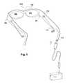
- FIG. 1shows one embodiment of the invention with a pair of glasses having speakers.
- FIG. 2shows a tube extending from a speaker at a temple of the glasses to guide sound to one of the ears of the user according to one embodiment of the invention.
- FIG. 3shows a retractable tube extending from a speaker at one of the temples of the glasses according to one embodiment of the invention.
- FIG. 4shows a funnel at the output of a speaker in the glasses according to one embodiment of the invention.
- FIGS. 5A-5Bshow an embodiment of the invention with a wire connecting speakers in the glasses.
- FIG. 6shows one embodiment of the invention with a pair of glasses having speakers that are wirelessly coupled to a portable device.
- FIGS. 7A-7Bshow different embodiments of the present invention illustrating some of the electrical components for wireless connections to a pair of glasses.
- FIG. 8shows a male stereo connector at the end of a temple according to one embodiment of the invention.
- FIG. 9illustrates a connector applicable to clamp onto a temple of a pair of glasses according to an embodiment of the invention.
- FIG. 10shows one embodiment of the invention with a pair of glasses having a microphone coupled to the wire connected to a portable device.
- FIG. 11shows different embodiments regarding frequency-dependent amplification of the present invention.
- FIG. 12shows a number of embodiments regarding hearing calibration of the present invention.
- FIG. 13shows a number of embodiments regarding power management of the present invention.
- FIG. 14shows different embodiments of sources of other audio signals generated by the glasses according to the present invention.
- FIG. 15is a flow diagram of call processing according to one embodiment of the invention.
- FIG. 16shows some of the electrical components for an MP3 player according to an embodiment of the invention.
- FIG. 17shows one embodiment of the invention that has a card with electrical components coupled to a pair of glasses through a connector at a temple of the glasses.
- FIG. 18shows a process for a personalized radio according to one embodiment of the present invention.
- FIG. 19shows a number of attributes of control knobs according to different embodiments of the present invention.
- FIGS. 20A-20Cillustrate different embodiments of power sources for a pair of glasses according to the invention.
- FIGS. 21A-21Bshow different embodiments of headset-to-phone cords according to the present invention.
- FIG. 22shows an embodiment of the invention of a cord with a switch for both a cell phone and a player.
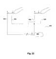
- FIG. 23shows one embodiment of a mono-plugs-to-stereo-plug adapter cord according to the invention.
- FIG. 24shows an embodiment of the invention with a speaker at a temple tip with an extension for attachment to a tube.
- FIG. 25shows an embodiment of the invention with the temples not extending behind the ears.
- FIG. 26shows an embodiment of the invention with a pair of eyeglasses functioning as a headset that has a camera, a microphone and a speaker.
- FIGS. 1-26Same numerals in FIGS. 1-26 are assigned to similar elements in all the figures. Embodiments of the invention are discussed below with reference to FIGS. 1-26 . However, those skilled in the art will readily appreciate that the detailed description given herein with respect to these figures is for explanatory purposes as the invention extends beyond these limited embodiments.
- the present inventionprovides different embodiments of glasses that can be applied to multiple functions. With a user wearing such a pair of glasses, it would be more difficult for a third party to know the specific function or reason the user is wearing the glasses for. Regarding the locations of the electrical components for the multiple functions, different embodiments range from all of the components in the glasses to the glasses primarily functioning as a headset.
- FIG. 1shows one embodiment of the invention with a pair of glasses 100 having speakers.
- the glasses 100include a first lens holder 102 and a second lens holder 104 . Both lens holders are for receiving lenses.
- the first lens holder 102has a first side and a second side.
- the second lens holder 104also has a first side and a second side.
- the pair of glasseshas a bridge element 106 .
- the bridge element 106is coupled to the first side of the first lens holder 102 and the second side of the second lens holder 104 .
- the lens holders and the bridge elementare not separate pieces, but are an integral piece.
- the pair of glasses 100also includes a first temple 108 and a second temple 110 .
- the first temple 108is pivotally secured to the second side of the first lens holder 102 through a joint.
- the second temple 110is pivotally secured to the first side of the second lens holder 104 through another joint.
- the glassesinclude one or more electrical components partially or fully embedded in the glasses.
- An electrical componentcan be a resistor, capacitor, inductor, transistor or other electrical part, other than just a conductor or a wire allowing current to flow between or among electrical components.
- An electrical componentcan also be more complicated such as an electrical circuit or an integrated circuit.
- FIG. 1shows one embodiment of the glasses 100 with electrical components that include two speakers, each at least partially embedded in the glasses.
- the speakerscan be used to enhance the hearing of the user wearing the glasses.
- each speakersuch as speaker 112
- Each speakeris closer to one end of the temple than the other end.
- each speakeris closer to the end of the temple that is in the vicinity of the lens holder or the hinge or the joint of the glasses, instead of the end that is typically not attached to a hinge.
- the end of a temple that is typically not attached to a hingecan be known as the free end of that temple.
- the speakerscan be partially embedded in the glasses. For example, the mouth of each speaker, where audio signals propagate from and where sometimes there are small holes on a sheet of material, can be exposed and not totally covered up by the temple.
- both speakersare embedded in the glasses, and the speakers output audio signals in the outward direction.
- the speakersoutput audio signals in the inward direction.
- the output of the speakerscan be facing inwards, towards the user.
- each speakercan be embedded in the glasses in a number of ways.
- each speakercan be first assembled onto or electrically coupled to a circuit board, which includes additional electrical components for the glasses.
- the glassescan be made of plastic (e.g., plastic frames).
- each circuit boardcan be shaped to fit, for example, into a temple of the glasses.
- Each circuit board with a speakeris placed into a mold. Then, hot, molten plastic is injection molded around each circuit board with the speaker to form the two temple pieces of the glasses.
- the wall of the glassescan be made relatively thin through injection molding techniques.
- the glasseshave metallic frames.
- the framescan be made of Titanium, which is a relatively light metal.
- Titaniumis relatively non-conductive and strong, and is quite immune to corrosion.
- Titaniumcan be anodized or heat colored.
- an insulating layerbetween a circuit board in the glasses and the corresponding metallic frame.
- an insulting layeris a tape to encapsulate the electrical components.
- the tapeis non-conducting so as to provide insulation and, to a certain degree, can also provide mechanical stiffness.
- One way to make such a templeis to have two sheets of the metal die-stamped to form the two halves, or the two faces of a temple piece.
- a circuit board with a speakeris made to fit into the space between the faces.
- two die-cut pieces of tapecan cover the top and the bottom surfaces of the circuit board.
- the board and the speaker with the tapeare sandwiched between the faces to form the temple.
- the tapecan be double-sided sticky tapes, with one side sticking to the circuit board, and the other side sticking to the temple.
- An adhesivecan be used to glue the two faces of the temple piece together.
- the framesare made of hard rubber.
- the framescan be manufactured in an approach similar to injection molding techniques, with circuit boards and/or speakers inserted into the mold along with the rubber at the time of molding.
- speakerscan be used, such as, standard, fixed-magnet/moving coil speakers; speakers with fixed-coil and a steel diaphragm; piezo-electric speakers; and electrostatic speakers.
- the glassesfurther include a tube, such as a plastic tube, extending from each speaker, such as tube 114 from speaker 112 .
- a tubesuch as a plastic tube, extending from each speaker, such as tube 114 from speaker 112 .
- Each tubeserves to guide sound generated by its corresponding speaker to one of the ears of the user.
- each tubeextends from its speaker to the opening of an ear canal of the user.
- FIG. 2shows an embodiment where a tube 114 is located on the outside of a temple 110 .
- the tubecan be on the inside of a temple.
- a tubecan be rotated, such as from along the temple (behind a temple if the tube is on the inside of the temple) to being downward at an angle towards one of the ears of the user, such as the position shown in FIG. 2 .
- the tubecan be attached to a rotating disk 116 , which allows rotation about the corresponding speaker.
- the tubeis malleable. This allows the tube to be placed in different positions.
- the length of the tubeis adjustable.
- FIG. 3shows such an embodiment of a pair of glasses with a retractable tube 118 .
- the tubeis shown to be in its extended position.
- the retractable tube 118can be retracted into the corresponding temple.
- the retractable tube 118can retract on itself (e.g., telescoping).
- a plug 115at the end of the tube 114 for inserting into an ear of the user, as shown in FIG. 2 .
- the plug 115can be an ear bud.
- the plug 115can provide a cushion of foam rubber or other materials. Such materials give comfort and/or enhance sound coupling to the ear canal.
- each ear budis individually made based on an impression of the user's corresponding ear canal. In another embodiment, each ear bud is custom fitted into the corresponding ear of the user.
- FIG. 4shows the cross section of such a funnel from a speaker 120 at a temple region of the glasses.
- the speaker 120sits on a speaker frame 122 , and the speaker 120 is electrically connected to a circuit board 124 .
- the soundpropagates to a tube 126 through a structure in the shape of a funnel 128 .
- Such a structurecan help guide the sound to the tube 126 (i.e., improved sound coupling).
- FIG. 4shows the tube 126 , which can be the tube 114 shown in FIG. 2 , mounted onto the temple region of the glasses with a circular lip 130 .
- Such a lip 130allows the tube 126 to rotate relative to the glasses.
- the speaker 120is embedded in the glasses.
- the tube 126is at the front side of the speaker 120 .
- a tubecan extend from the back side of the speaker to couple the sound from the speaker to an ear.
- the two speakerscan also be electrically connected by a conductor or an electrical wire, with the conductor linking the speakers through the glasses, such as through the lens holders of the glasses.
- FIGS. 5A-5Bshow an embodiment of the wire 130 , with FIG. 5A illustrating a hinge 132 of the glasses in the extended position, and FIG. 5B illustrating the hinge 132 partially closed.
- the wire 130is embedded in a temple 134 to connect to the speaker in that temple.
- the wire 130extends from the temple 134 to a lens holder 136 , and then to the other temple of the glasses to connect to the speaker in the other temple.
- electrical components in the glassescan also include at least one microphone 98 , which can be located at a temple 110 , closer to the hinge than the free end of that temple 110 .
- the microphone 98receives audio signals.
- the audio signalsare modified or enhanced (to be further described below), and then sent to the speaker(s) in the glasses for the user to hear.
- the usercan hear both the enhanced sound based on hearing enhanced electrical components and sound directly from the ambient environment.
- each microphonecan, for example, be located close to one hinge of the glasses.
- the microphone close to the left hingecan be electrically connected to the speaker at the left temple, and the microphone close to the right hinge can be electrically connected to the speaker at the right temple.
- the one or more microphonescan be directional, more preferential towards signals in specific directions. For example, the microphone close to the left hinge can be more preferential towards signals coming from the left, and the microphone close to the right hinge more preferential towards signals from the right.
- some of the electrical componentsare not in the glasses. Instead, they are in a base or a portable device carried or worn by the user.
- a baseA number of embodiments regarding a base have previously been described in U.S. patent application Ser. No. 10/964,011, entitled “TETHERED ELECTRONIC COMPONENTS FOR EYEGLASSES,” and filed Oct. 12, 2004, which is hereby incorporated by reference.
- the baseIn embodiments with the base, the base is tethered, or connected with a wire, to the glasses.
- the portable deviceis electronically coupled to the glasses or to the base (if there is a base) wirelessly or through a wired connection.
- FIG. 6shows one embodiment of the invention with a pair of glasses 150 having speakers.
- the glasses 150can be wirelessly coupled to a portable device 152 .
- FIG. 6shows the microphone 154 in a package that can include a clip 156 to attach the microphone 154 to a piece of clothing of the user, such as to one of the lapels on a jacket of the user.
- the glasses 150also include a wireless transceiver for connection to the portable device 152 and/or the microphone 156 .
- FIGS. 7A-7Bshow examples of different embodiments illustrating some of the electrical components for wireless connections to, or for a wireless transceiver in, a pair of glasses.
- a high frequency or RF antenna 170wirelessly captures high frequency or RF signals for RF transceiver circuits 172 .
- the transceiver circuitsare for a conventional superheterodyne system, the transceiver circuits 172 mix the RF signals down to IF signals. Then the IF signals are processed by baseband circuits to form digital outputs. Digital outputs from the baseband circuits are coupled to a processor 174 for further processing.
- the baseband circuitscan be incorporated in the processor, or can be separate from and coupled to the processor. Outputs from the processor 174 are fed to a D-to-A converter 176 to generate audio signals for a speaker 178 .
- audio analog signals from a microphone 180can be fed to an A-to-D converter 182 to generate digital signals for the processor 174 and then to the baseband circuits and the RF transceiver circuits 172 .
- the digital signalsare then up-converted by the RF transceiver circuits 172 and wirelessly transmitted by the antenna 170 .
- digital conversionis moved closer to the antenna.
- the RF transceiver circuitsdirectly perform digital conversion from the RF signals.
- High frequency filterscan be used at the front end of the RF transceiver circuits for the RF signals.
- FBARfilm bulk acoustic resonator duplexer
- a set of piezoelectric filterscan be used to separate incoming and outgoing signals. For cell phone operation (which will be further described below), such filters can enable a user to hear and speak simultaneously.
- FIG. 7Bshows another example of some of the electrical components in or tethered to a pair of glasses for wireless connections.
- a speaker 190 and a microphone 192are connected to an analog interface circuit 194 , which is coupled to a RF transceiver circuit 196 and an antenna 198 .
- the transceiver circuit 196converts the RF signals down into IF signals, which are converted by the analog interface circuit 194 into analog signals for the speaker 190 .
- the microphone applicationits analog signals are converted into the IF signals by the analog interface circuit 194 to be up converted by the RF transceiver circuits 196 into RF signals for the antenna 198 .
- These types of wireless connection circuitryare suitable, such as, for simple radios, analog cell phones, CB radios, walkee-talkees, police radios, intercom systems, or hearing enhancement applications.
- signals from the microphonesare transmitted by a wired connection, instead of a wireless connection.
- the electrical componentsare not in the glasses. Instead they are in a base or a portable device, which can be carried by the user.
- the portable devicecan be electrically coupled to the glasses through a wired connection.
- the glassesalso include at least one connector to receive an electrical wire from the base or the portable device.
- the connectorcan be at the free end of one of the temples of the glasses, or the connector can be at another location of the glasses.
- Different types of standard or non-standard connectorscan be used and have previously been described in U.S. Provisional Application No. 60/583,169, filed on Jun. 26, 2004, which is hereby incorporated by reference.
- a standard cylindrical plug connectoris located at one end of a temple. From a different perspective, the temple molds around the end of the plug.
- FIG. 8shows one such embodiment.
- the plug 220can be a standard audio connector or a 3-wire or three terminal plug, such as a 3.5 mm male stereo mini-phone plug.
- the 3 wires for such a plugare typically one for ground, the other two applicable for two signals, such as signals for two speakers to create stereo effects.
- FIG. 8also shows the three wires 222 , 224 and 226 , inside the temple, extended from the plug 220 . These wires are for connection to electrical components in the glasses.
- the cylindrical plug 220 shown in FIG. 8can be covered, such as with a cap or a cover, to protect, encapsulate or shroud the plug 220 . Or, at least a portion of the plug is covered. Such covering can be for esthetic reasons, or can be to prevent the plug 220 from scratching the face of the user (if the plug has relatively sharp edges) when the user is putting on the pair of glasses.
- a serial connector with 3 pinstypically one for ground, one for transmitting data (Tx) and the third for receiving data (Rx); or a 2-wire connector, one served as ground, the other for carrying signals, such as power and modulated signals.
- a connectorcan be a non-standard connector.
- FIG. 1shows a non-standard connector 113 at the free end of one of the temples 110 .
- a connectorcan be at another location of the glasses.
- FIG. 9shows an example of a non-standard connector 230 .
- the connector 230includes one or more conductive pads, 232 and 234 , on the top side of a temple 236 .
- the connector 230is designed to receive another connector 240 that grabs onto or attaches around the side of the temple.
- the other connector 240can include a top 244 and a bottom 246 clip.
- the indentation 242provides alignment for connection. When attachment is at the indentation 242 , the conductive pads, 232 and 234 , at the temple 236 will be in contact with the conductive pads or sheets in the other connector 240 . There can also be another indentation 248 at the temple 236 to receive the bottom clip 246 . This can further enhance the alignment process and assist with securing the connection.
- the other connector 240is tethered to a plug 250 , which can be inserted into a portable device 252 .
- the portable device 252can be a cell phone.
- the portable devicecan include personal digital assistant (PDA) functionalities. This type of non-standard clip-type connector could be relatively easily applied to the temple with one hand, for example, while the user is driving a car.
- PDApersonal digital assistant
- a microphonedoes not have to be in the glasses.
- a microphone 254can be attached to the wire 256 that connects the glasses to the portable device 252 .
- FIG. 10shows one embodiment of the invention with a pair of glasses 260 having a microphone 262 coupled to a wire.
- the wireis connected to a portable device 264 through a plug 266 , and to the glasses 260 through a jack 268 .
- the portable device 264can be in a shirt pocket as shown.
- the glassesinclude electrical components for hearing enhancement functionalities.
- the electrical componentsenhance audio signals, such as audio signals received by a microphone at the glasses. Then the enhanced signals are sent to the speakers for the user to hear.
- the hearing-enhancing electrical componentsinclude a processor.
- the processorcan be the processor 174 shown in FIG. 7A .
- the hearing-enhancing functionalitiesare performed through digitizing the corresponding audio signals. Then the processor, using digital signal processing techniques, operates on the digitized signals, such as boosting specific frequency bands.
- the hearing enhancing functionalitiesare provided by analog filter circuits.
- analog filter circuitsusing analog processing techniques, operate on the audio signals, such as boosting specific frequency bands.
- one hearing enhancement functionincludes amplifying the audio signals received in a frequency range between 500 Hz to 8 kHz.
- a user's hearing impairmentis not the same across all audio frequencies. For example, in English, the user might be able to easily pick up the sound of vowels, but not the sound of consonants, such as “S” and “P”.
- FIG. 11shows a number of embodiments regarding frequency-dependent amplification of the received audio signals.
- One approach for frequency-dependent amplificationfocuses on amplifying the higher audio frequency ranges. This approach assumes that hearing degradation typically starts at the higher audio frequencies, such as above 2 to 3 kHz. Hearing may need more assistance at the higher audio frequency range.
- the audio signals received by a microphonecan be amplified by 30 dB in the frequency range from 2 kHz to 4 kHz. Or around the entrance of the ear, the audio signals in that frequency range can be amplified to reach sound pressure level (“SPL”) to about 80 dB.
- SPLsound pressure level
- the amplificationcan be lower, such as 10 dB.
- the maximum SPLdoes not have to be higher than 55 dB.
- Another frequency-dependent amplification approachfocuses on amplifying an audio frequency range that typically contains most of the information in everyday communication. For example, about 70% of the information in everyday human communication can be within the frequency range of 1 to 2 kHz.
- the frequency range that is selected to be amplifiedcan be such a frequency range. Other frequency ranges are not selected for amplification.
- the ear canalremains open, with no plug inserted into the ear.
- the usercan be hearing the audio signals directly from the sender (i.e., without assistance provided by the hearing enhancement electrical components).
- the embodimentsfurther implement frequency-dependent amplification, for frequencies not within the ranges selected for amplification, the user can hear those signals directly from the sender.
- Lower frequenciessuch as those below 2 kHz, are typically louder.
- frequencies in the rangesuch as from 2000-3000 Hz, are typically in the natural resonance of the ear canal, which is typically around 2700 Hz. As a result, the intensity of these frequencies would be increased by about 15 dB.
- signal processing speed of the frequency enhancement electrical componentscan be important.
- the usercan be hearing the audio signals both from the sender and the glasses' speakers.
- signal processing speed for hearing enhancementcannot be too low.
- the userwould not be able to distinguish two identical sets of audio signals if the difference in arrival times of the two signals is below a certain delay time, such as 10 milliseconds.
- the hearing enhancement signal processing speedis faster than such a delay time.
- the userhas the option of manually changing the amplification of the system.
- the systemcan have a general volume controller that allows the user to adjust the output power of the speaker. This adjustment can also be across certain frequency bands. For example, there can be three volume controls, each for a selected frequency band.
- FIG. 12shows a number of embodiments regarding calibration of a user's hearing, for example, across various frequencies and/or for different amount of amplification. Calibration enables the glasses to determine (e.g., estimate) the hearing sensitivity of the user. Through calibration, the user's hearing profile can be generated.
- the usercan perform the calibration by himself/herself. For example, the audio frequencies are separated into different bands.
- the glassesgenerate different SPL at each band. The specific power level that the user feels most comfortable would be the power level for that band.
- the glassescould generate different tones in different frequency bands. The user could compare the tones and rate the perceived loudness. In this process, the glasses can prompt the user and lead him through the process interactively. Based on the measurements, the glasses could create a calibration curve, which becomes the personal hearing profile for that user. After calibration, signals received in different bands, such as by a microphone in the glasses, will be amplified or attenuated according to the hearing profile.
- calibrationcan be done through a web site.
- the web sitecan guide the user through the calibration process.
- the usercan be sitting in front of a computer terminal that is connected through the Internet to the web site.
- the terminalincludes a headset that produces audio sounds.
- the usercould be wearing the glasses that are connected through a cable to the sound card of the computer.
- the headset(or the glasses) generates different SPL at different frequency bands to test the user's hearing.
- the specific power level that the user feels most comfortablewould be the power level at that band for the user.
- the web sitecreates and stores the user's personal hearing profile.
- the calibration procedurecould be done off-line, with software provided on a storage device, such as a disc.
- the softwarecould be installed on the user's computer. After installation, the software can guide the user through the calibration process.
- the different calibration processescan also be done by a third party, such as an audiologist, for the user.
- the user's hearing profilewhich typically is represented as digital data, can be stored in the glasses, in a base, or in a portable device. After calibration, the hearing profile can be downloaded, from, for example, the above described terminal, into the glasses wirelessly, such as through Bluetooth, infrared or other wirelessly interconnection technologies, or through a wired connection.
- the hearing profilecan alternatively be stored in a portable media storage device, such as a memory stick. The memory stick could be inserted into the glasses, the base, the portable device, or some other audio generating device, which desires to access the hearing profile and personalizes the amplification across frequencies for the user.
- the glassescan also periodically alert the user for re-calibration.
- the periodcan be, for example, once a year.
- the calibrationcan be done in stages so that it is less onerous and/or less obvious that the user is wearing a hearing enhancing device.
- each pairamplifies the received audio signals in a preset frequency range by a preset amount. For example, two pairs amplify two respectively different preset frequency ranges by 20 dB.
- each pairprovides different amount of amplification for the received audio signals in the same preset frequency range. For example, the different amount of amplification ranges from 20 to 40 dB at 5 dB intervals for the preset frequency range of 2500 to 4000 Hz.
- a consumercan try out different glasses with different preset amplifications at the same or different preset frequency ranges, before buying the one the consumer prefers.
- the glassesinclude hearing enhancement capabilities, the hearing enhancement functions might be on continuously for a long duration of time, power consumption can be an issue.
- the glassesalso include electrical components that are for managing power consumption of other electrical components in the glasses, such as the components to enhance hearing or other functionalities in the glasses.
- the electrical componentcan be a power controller, a microprocessor, or the processor 174 in FIG. 7A .
- Such glassescan include power management software applications/processes to manage power consumption of the glasses.
- FIG. 13shows a number of embodiments for managing power consumption of the glasses.
- One embodimentincludes a manual on/off switch, which allows the user to manually turn off the electrical components in the glasses as he desires.
- the on/off switchmay not have to be on the glasses. It can be on a base or a portable device tethered to the glasses.
- the operation of the electrical componentscan be on-demand.
- the on/off switchcan be voice activated.
- the glassesare trained to recognize specific recitation, such as specific sentences or phrases, and/or the user's voice. To illustrate, when the user says sentences like any of the following, the hearing enhancement capabilities would be automatically turned from the sleep mode to the active mode: What did you say? Louder. You said what?
- the glassescan identify noise (e.g., background noise), as opposed to audio signals with information.
- noisee.g., background noise
- the glassescould assume that the received audio signals are noise.
- the glasseswould assume that there are no audio signals worth amplifying.
- the amplitude or the power level of the received audio signalsis below a certain threshold for a duration of time, at least some of the electrical components in the glasses can be deactivated. This duration of time can be adjustable, and can be, for example, 10 seconds or 10 minutes.
- the deactivated electrical componentsbe activated (i.e., awakened from the sleep mode, the reduced power mode or the standby mode).
- the glasses or the hearing enhancement capabilitiescan be placed into a sleep mode, a reduced power mode or a standby mode.
- Another approach to manage power consumptioncan make use of a directional microphone. This approach can improve the signal-to-noise ratio.
- the gain at specific directions of such a microphonecan be 20 dB higher than omni-directional microphones.
- the direction of the directional microphonecan vary with application. However, in one embodiment, the direction of the directional microphone can be pointing forward or outward away from the user. The assumption is that the user typically faces the sender of the message, and thus it is the audio signals in front of the user that should be enhanced.
- the amplification of the glasses on at least a range of frequenciesdepends on the ambient power level, or the noise level of the environment of the glasses.
- One approach to measure the noise levelis to measure the average SPL at gaps of the audio signals. For example, a person asks the user the following question, “Have you left your heart in San Francisco?” Typically, there are gaps between every two words or between sentences or phrases.
- the glassesmeasure, for example, the root mean square (“rms”) value of the power in each of the gaps, and can calculate another average among all of the rms values to determine the noise level.
- the glassesincrease the amplification so as to ensure that the average power of the output audio signals by its speaker(s) is higher than the noise level by a certain degree. For example, the average SPL of the output audio signals from the glasses is 20 dB above the noise level.
- the average power level of the environment or the ambient noise levelis higher than a preset threshold value, signal amplification is reduced.
- This average power levelcan include all the audio signals received by, such as the microphone(s) of the glasses.
- the rationaleis that if the environment is very noisy, it would be difficult for the user to hear the audio signals from the other person anyway. As a result, the glasses should not keep on amplifying the audio signals independent of the environment.
- hearing enhancement amplificationis reduced, such as to 0 dB.
- the glassesfurther include automatic activation/deactivation mechanism controlled by a sensor that determines whether the user is wearing the eyeglasses.
- a sensorthat determines whether the user is wearing the eyeglasses.
- At least one electrical component in the glassesis for generating audio signals that do not originate from signals captured by the microphone(s) in the glasses. These audio signals can be known as other audio signals.
- FIG. 14shows different embodiments of the sources of such other audio signals. These signals can originate from relatively private sources or public sources.
- the other audio signalsoriginate from a phone call received by the glasses.
- a pair of glassescan include wireless communications electrical components of a phone.
- the phonecan be a mobile telephone, a cordless phone, a speaker phone, a CB radio, a walkee-talkee, an intercom system or other types of phone.
- the wireless communications electrical componentscan be located in at least one of the temples of the glasses. Some of the electrical components of the phone can be in a base or in a portable device wired or wirelessly coupled to the glasses.
- the glassescan pick up signals from a caller, and the speaker(s) in the glasses produce the audio signals, or a representation of the audio signals, from the caller.
- the indicatorcan be based on, for example, sound, light or vibration.
- the indicationis based on light, and is located on the inside of a temple close to the hinge of that temple.
- Such an operation indicatorcan be implemented in a variety of ways, such as with a light emitting diode (LED).
- LEDlight emitting diode
- the operation indicatoris a light source, and can produce light of the color of the LED.
- the operation indicatorcould represent a small text display, such as a liquid crystal display (LCD).
- the indicatorcan also be a signal light.
- activation/deactivation of the phoneis based on whether an incoming call is present. For example, on receiving an incoming call, the glasses can automatically activate (or wake-up) to engage in wireless communication. Activation/deactivation can also be triggered by a button provided on the frame of the glasses. The button can serve to accept or drop a call.
- One advantage of providing activation/deactivationis that the glasses are able to be power managed so that power consumption is reduced and the life of power sources, such as battery life, is extended.
- FIG. 15is a flow diagram of call processing 300 according to one embodiment of the invention.
- the call processingis performed using glasses disclosed in different embodiments that have wireless communication capabilities.
- the glassescan be based on the glasses shown in FIGS. 1 or 9 .
- the call processingbegins with a decision 302 that determines whether a call is incoming. When the decision determines that a call is not incoming, then the call processing waits for such a call. Once the decision 302 determines that a call is incoming, the glasses are activated 308 . Here, the wireless communications capability of the glasses is activated (e.g., powered-up, enabled, or woken-up). The user of the glasses is then notified 310 of the incoming call. In one embodiment, the notification to the user of the incoming call can be achieved by an audio sound, such as a ringer, produced by the glasses (via a speaker). Alternatively, the user of the glasses could be notified by a vibration (such as by a base tethered to the glasses), or a visual (e.g., light) indication provided by the glasses.
- a vibrationsuch as by a base tethered to the glasses
- a visual indicatione.g., light
- a decision 312determines whether the incoming call is to be answered. For example, the user can push a button to indicate that the user wants to answer the call.
- the glassescan activate a voice message informing the caller to leave a message 314 or instructing the caller as to the unavailability of the recipient.
- the callcan be answered 316 at the glasses.
- the user of the glassesis accordingly able to communicate 320 with the caller by way of the glasses and, thus, in a hands-free manner.
- a decision 322determines whether the call is over (completed). When the decision 322 determines that the call is not over, the call processing returns to repeat the operation 320 and subsequent operations so that the call can continue. On the other hand, when the decision 322 determines that the call is over, then the glasses can be deactivated 324 , and the call is ended.
- the deactivation 324 of the glassescan place the glasses in a reduced-power mode. For example, the deactivation 324 can power-down, disable, or sleep the wireless communication capabilities (e.g., circuitry) of the glasses. Following the operations, the call processing for the particular call ends.
- a wireless linkcan be established between the headset and the portable device if the incoming call is to be answered.
- the wireless linkis, for example, a radio communication link such as utilized with Bluetooth or Wi-Fi networks. Thereafter, communication information associated with the call can be exchanged over the wireless link.
- the portable devicereceives the incoming call, and communicates wirelessly to the glasses such that communication information is provided to the user via the glasses.
- the wireless linkis also ended 326 .
- hearing enhanced capabilitieswhen there is an incoming call, hearing enhanced capabilities are deactivated, and the glasses receives the incoming call. In another embodiment, when the user wants to receive the incoming call, one or more embodiments of the hearing enhanced capabilities enhance the audio signals from the incoming call.
- the glassesalso include electrical components for noise cancellation. Such noise cancellation functionalities can be activated during a phone conversation.
- noise cancellationis achieved through a first and a second directional microphones.
- the first onepoints at the user's mouth, and the second one points away.
- the first onecan be at one of the hinges as shown in FIG. 1 , whose directionality favors sound arriving from the user.
- the second microphonecan be in the vicinity of the other hinge, whose directionality favors sound arriving in front of or outside of the user. Signals received from the second microphone are subtracted from signals received from the first microphone before the audio signals are further processed for transmission as the message from the user.
- audio signals originating from private sourcesinclude the other audio signals originating from different types of audio players, such as televisions, stereo systems, media asset players, or radios.
- the audio playerscan be in the glasses.
- at least some of the electrical components of the audio playerscan be in a base tethered to the glasses, or in a portable device wired or wirelessly coupled to the glasses.
- the other audio signalscan originate from a portable device, which might produce, receive or play audio content.
- the audio contentis then transmitted to the eyeglasses in a wired or wireless manner.
- the eyeglassesserve as a receiver of the audio content from the portable device and reproduce the audio signals for the user.
- the glasses with the call processing abilityperform two-way communications.
- the glassesperform one-way communications (or at least substantially one-way communications).
- a pair of glassesincludes electrical components of a headset for wirelessly receiving audio signals. Assume the user is working in the backyard and the stereo system is in the living room. The music from the stereo can be wirelessly transmitted to the glasses or to a portable unit carried by the user, which can re-transmit the music to the glasses wired or wirelessly. The speakers in the glasses can generate the music for the user to enjoy. Based on this technique, the user can enjoy the music without the need to crank up the volume of the stereo system.
- a pair of glassesincludes a multimedia asset player, such as a MP3 player.
- FIG. 16shows some of the electrical components for an MP3 player 340 according to one embodiment of the invention.
- the player 340includes a speaker 342 and a data bus 343 , which facilitates data transfer among, for example, a processor 344 , a storage device 345 , and a coder/decoder (CODEC) 346 .
- the processor 344which can be a microprocessor or controller, controls the operation of the player 340 .
- the storage device 345stores the multimedia assets, such as MP3 files, or other types of media data that are appropriately formatted.
- the MP3 filesare digitally encoded songs or other types of audio signals.
- the storage device 345can include a number of separate storage elements.
- the device 345can be a flash memory device, or a minidisk device, and a cache, which can improve the access time and reduce power consumption of the storage device 345 .
- the storage device 345typically also includes a Read-Only Memory (ROM), which stores programs, utilities or processes to be executed in a non-volatile manner.
- ROMRead-Only Memory
- the player 340can also include a RAM, such as for the cache.
- the processor 344supplies the asset to the CODEC 346 , which decompresses the asset and produces analog output signals for the speaker 342 .
- the bus 343is also coupled to an input/output device 347 , which could, for example, allow a user to upload songs in the glasses to an external instrument, such as a computer; or download songs from the instrument to the glasses.
- the media assets/songscan be categorized in the asset player.
- the categorizationcan be based on the names of artists, albums and/or songs.
- the categorizationcan be hierarchical, with multiple levels in the hierarchy. To illustrate, assume that there are three levels. The top level can be the name of a singer; the second level can be the time periods when the assets were produced, and the third level can be the names of the songs.
- the entriessuch as the name of the singer, can be abbreviated.
- the displayis a touch-screen display, allowing entries to be entered directly on the display.
- entriescan be selected based on voice recognition.
- FIG. 17shows a card connector 350 to receive a card 352 , such as a removable media card (e.g., memory card).
- a card 352such as a removable media card (e.g., memory card).
- the cover 354can also protect the card once the card is in the card connector.
- the connector 350can be, for example, at a broad side of a temple 356 , as shown in the figure.
- the cardcan be for an MP3 player.
- Itcan be a memory card for a MP3 player, with the speaker of the player in the temple 356 .
- the speakercan play the multimedia assets accessed from the card through the connector.
- some of the electrical components of the different types of audio playerscan be in a portable device, wired or wirelessly coupled to the glasses.
- FIG. 1shows two speakers, one speaker at one of the temples.
- the two speakerscan provide stereo effects.
- the glassescan provide four or more speakers to give a high fidelity sound or a surround sound effect.
- each templecan include one speaker close to the hinge, and one speaker close to the tip of that temple or its temple tip.
- a temple tipis separable from its temple.
- the temple tipis a replaceable part.
- a temple tipis an integral part of its temple.
- the different speakerscan generate different portions or sections of the sound.
- the base or the portable electronic devicecan contain another speaker, such as a base or woofer speaker.
- a base or woofer speakerSuch embodiments enable the glasses to provide a personal high-fidelity sound or a surround-sound environment.
- the audio playercan be a radio.
- the glassesinclude the electrical components of a radio.
- one switchis an on/off switch, which can also change the volume of the radio.
- This switchcan be a roller switch or can be based on two switches (one for moving up and the other moving down).
- Another switchcan be a push button, which when pushed will reset the radio to a specific station, such as 88 MHz.
- a third switchis another push button, which when pushed will scan up to the next station, relative to the previous station.
- Different types of control knobs or switcheswill be further described below.
- the radiois a personalized radio that is personalized to the user.
- the radiokeeps track of at least one preference of the user regarding audio signals from the radio received by the user.
- FIG. 18shows a process 375 according to one embodiment for a personalized radio.
- a pair of glasses according to the inventionreceives 377 a piece of music from a radio station. That piece of music is stored 379 in a buffer or a temporary storage area. This temporary storage area can be in the glasses or tethered/coupled to the glasses. The piece of music is also sent 381 to a speaker in the glasses.
- the glassesdetermine 385 the song corresponding to the indication. That piece of music can then be moved 387 from the buffer to a permanent storage area, such as into a flash memory. The beginning and the end of the piece of music can be identified based on additional information embedded with the piece of music. There can be meta data tied to the music keeping such additional information. With the piece of music stored in the permanent storage, the user can subsequently access it as desired.
- one way/ruleis that when the user pushes a specific button (a preference button) on the glasses or voices his preference, the song (or media asset or media file) that is being played at that point in time is the one the user likes. Since an operating system can be responsible to send the music to the speaker, the operating system knows what song is being played at that time. Based on the rule, the song of preference is determined when the button is pushed. Another rule is that when the user shows his preference, and there is no song being played at that instance, the song immediately preceding the break is the song of preference.
- the glassescan get 389 an identification for the song the user likes.
- the glassescan ask the user to provide an identification for the piece of music.
- This identificationcan be the type of music, the name of the singer/artist, the name of the music, the name of the album or other identification.
- the meta datacan include identifications for the music.
- the glassescan get such identification. Based on the identification, the song is categorized 391 accordingly, such as grouped with other songs having the same identification. Such categorization process would enhance the ease of accessing the song by the user at a later time.
- the hearing enhancement modewhen the user activates the different types of audio players, the hearing enhancement mode is deactivated. In another embodiment, when the user activates the different types of audio players, one or more features of the hearing enhancement capabilities operate on the audio signals from the audio players. In other words, different embodiments of the hearing enhancement capabilities previously described can be activated or deactivated on the audio signals from the different types of audio players.
- the audio signals generated by the speakerscan originate from a public source.
- the public sourcecan be a source that generates the audio signals for many people, or for people in a public environment.
- the usercan be at a conference or a theater.
- the glassescan be coupled to the conference microphone or the theater speaker wirelessly, and are capable of capturing the audio signals therefrom. Again, the coupling can be through a portable device wired or wirelessly connected to the glasses. Then the glasses re-generate the corresponding audio signals for the user.
- different embodiments of the hearing enhancement capabilities previously describedcan be activated or deactivated on the audio signals from the public sources.
- FIG. 19shows a number of attributes 400 regarding control knobs.
- the knobscan be of different physical structure 402 .
- a control knobcan be a roller, a switch or a push-button.
- a control knob serving as an up/down controllercan use two buttons (one for up and the other for down), or a roller (rolling in one direction being up and the other direction being down).
- a control knobcan include additional intelligence 404 .
- a push-button control knobcan serve different purposes depending on the duration the knob is being pushed. If a user pushes it for more than three seconds, the knob serves as an on-off toggle switch for the glasses. In another example, a knob can serve multiple purposes, and the specific purpose depends on the number of times the knob is pushed non-stop.
- a knobcan also be programmed by a user.
- a usercan connect the glasses to a computer and program the knob accordingly. For example, one can program a knob such that if the knob is pushed for more than three seconds, the knob would serve as an on/off switch for the glasses.
- a control knobcan be located on the glasses.
- a control knobcan be on the top, the side or the bottom of a temple of the glasses.
- a control knobcan be located at the inside of a temple facing the user.
- this knobcan serve a specific purpose. For example, it can be an on/off control knob for all of the electrical components in the glasses.
- a control knobcan be located in a portable device wired or wirelessly coupled to the glasses, or in a base tethered to the glasses.
- the number 408 of control knobscan vary depending on operations. For example, there is an on/off control knob and a volume up/down control knob. If the glasses are used for cell phone headset applications, in one embodiment, there is also an answer/hang-up control push-button. If the glasses serve as a radio, in one embodiment, there is also a channel selection control knob, which can be an up/down controller, like two push buttons. If the glasses serve as a CD player, in one embodiment, there is a play control knob, a stop control knob, and a skip forward/backward control knob. If the glasses serve as a multimedia asset player, such as a MP3 player, in one embodiment, there is a skip-forward/backward-song control knob and a select-song-to-play control knob.
- a pair of glassescan serve different applications.
- a switch on the glasses(a base or a portable device coupled to the glasses) can also serve different functions, depending on the application.
- switchesare applicable for different applications. Additional disclosures on switches are in U.S. Provisional Application No. 60/583,169, filed on Jun. 26, 2004, which is hereby incorporated by reference.
- the power sourceswhich can be batteries and/or solar cells, are in the glasses.
- one or more batteriescan be inserted into the glasses.
- the batteriescan be of various sizes and types.
- a coin battery 420e.g. CR1025
- FIG. 20Bshows the embodiment shown in FIG. 20A with a bigger coin battery 422 (e.g. CR2032) inserted into the slot. Since the size of the battery is bigger than the size of the slot, a portion of the battery 422 sticks out of the slot.
- FIG. 20Cshows another embodiment of the glasses that include a slot/cavity to receive a battery adapter 426 .
- the slot 418 in FIG. 20Acan be the same as the slot 424 in FIG. 20C .
- the adapter 426can be the same size and shape of the battery shown in FIG. 20A , and with two terminals, just like the battery. However, the adapter, by itself, is not an energy source.
- the adapteris connected to a cable 428 , with at least two wires inside, one for each terminal of the adapter.
- the adapter 426is inserted into the cavity 424 of the glasses, and is coupled through the cable 428 to a case or a capsule 430 that holds a battery 432 .
- the two wires in the cable 428are for the two terminals of the battery 432 .
- the size and capacity of the battery held by the capsulecan be bigger than the coin battery, and could be less expensive than the coin battery.
- the capsule 430holds an AA battery. Note that in one approach, the temple in FIG. 20C is the same as the temple in FIG. 20A .
- the power sourcesare in a base or a portable device connected to the glasses through a wire connection, and the power sources can be rechargeable.
- some of the electrical components for hearing enhancement and/or for generating other audio signalsare in a base tethered to the glasses. In other embodiments, some of the electrical components are in a portable device, wired or wirelessly coupled to the glasses. In yet other embodiments, all of the electrical components are in the glasses.
- the glassescan be a pair of sunglasses, auxiliary frames, fit-over glasses, prescription glasses, reading glasses, safety glasses, swim masks, or goggles, such as ski goggles.
- the frames of the glasseshave more surface area than frames with minimal structure, such as those frames with lenses connected together by wires.
- the temples of the glassescan have a taper profile.
- Each of the templescan be wider or broader when it is close to its corresponding joint.
- the templeis wider or broader by spanning across a wider or broader area longitudinally down, creating a bigger surface somewhat parallel to the face of the user.
- FIG. 1shows an example of such an embodiment.
- a shieldat least at one of the edges of each of the lens holders of the glasses.
- These shieldscan wrap around, or better conform to the profile of, the face of the wearer.
- the shieldscan be opaque. There can be transparent or translucent windows on these shields.
- sunglasseswhen worn over a pair of prescription glasses, such shields can go over or cover at least a portion of the pair of prescription glasses.
- a pair of glassesdoes not have to include lenses.
- At least one electrical componentis in other parts of the glasses, such as in a shield, the bridge or a lens holder of the eyeglasses.
- glassesinclude hearing enhancement capabilities and can generate one or more types of other audio signals.
- electrical components for such functionalitiescan be shared. For example, different functionalities can share the same power source, or the same processor/controller.
- the glasses with hearing enhancement capabilitiesalso generate other audio signals
- different embodiments of the glassesonly have hearing enhancement capabilities.
- the glassesdo not have hearing enhancement capabilities, but generate other audio signals.
- the glassesfunction as a headset and are adaptable for different applications, such as hearing enhancement, communication (e.g. phone operation) or listening to other audio signals (e.g. MP3 operation).
- the userinitially can use the glasses as the headset for a phone or an MP3 player. Later, as the user's hearing degrades, the user can use the glasses as the headset for hearing enhancement or hearing boosting.
- a third partymay not be able to tell whether the person is having his hearing enhanced, or listening to other audio signals.
- the glassescan include a connector and two speakers, one at each temple, both electrically connected through a conductor embedded in the glasses.
- the conductorcan be a wire, similar to the embodiments shown in FIGS. 5A-5B .
- the connectorcan be located at the free end of one of the temples, such as the embodiment shown in FIG. 8 .
- the connectorcan be a standard connector, such as a 3-wire or three terminal plug, or a 3.5 or 2.5 mm male stereo mini-phone plug.
- the three terminalscan be for the two speakers and ground, with both speakers sharing the same ground.
- the positive terminal of the left speakeris connected at the first terminal of the plug
- the positive terminal of the right speakeris connected to the second terminal of the plug
- the ground terminals of the speakersare connected to the third terminal of the plug.
- the plug at the glassescan be used to receive stereo signals for the two speakers.
- the stereo signalscan be from a separate audio source, such as an MP3 player or a radio.
- the female connector of the cordis for receiving the plug at the glasses, while the male connector of the cord is for inserting into the headset jack of the player or the radio.
- the headsetcan be used as the headset for a cell phone. Phone calls can be made with the headset using a headset-to-phone cord.
- FIGS. 21A-21Bshow two embodiments of such a cord.
- the cordincludes a female stereo mini-phone jack at one end and a male stereo mini-phone plug at the other end.
- the three terminals at the stereo mini-phone plugcan be designated as the m (microphone), s (speaker), and g (ground) terminals.
- FIG. 21Ashows one approach 450 for the wiring connections in a headset-to-phone cord.
- One end of the cordcan have a female stereo mini-phone jack for connection to the plug 452 at a temple tip 454 of a pair of glasses.
- the female jackis not shown in FIG. 21A .
- the other end of the cord 450has a stereo plug 456 , with three terminals, the m 460 , the s 464 and the g 462 terminals.
- the plug 456is for inserting into the headset jack of the phone.
- the two speakers in the glassesare connected in series, and the microphone 458 for the phone is attached to the cord, similar to the microphone 254 shown in FIG. 9 .
- the microphone 458is connected with wires between the m 460 and the g 462 terminals for the user to speak into.
- the negative terminal of the microphone 458is extended through a wire to connect to the ground terminal 462 within the plug 456 .
- the positive terminal for one speakeris connected to the s 464 terminal, and the positive terminal for the other speaker to the g 462 terminal.
- the two negative terminals of the two speakersare connected together (such as inside the glasses) to complete the circuit. In this embodiment, both speakers are connected in series and the audio signals of the caller go through both of them.
- FIG. 21 Bshows another approach 470 for the wiring connections in a headset-to-phone cord.
- the two speakers in the glassesare connected in parallel.
- a microphone 472is connected between the m 474 and the g 478 terminals.
- the negative terminal of the microphone 472is extended through a wire to connect to the g 478 terminal at a location within the plug 480 .
- the positive terminals for both speakersare connected to the s 476 terminal, and the negative terminals of both speakers to the g 478 terminal.
- the microphone 472is external to the glasses and is attached to the cord 470 .
- the glassescan be used as the headset of a telephone, such as a cell phone. Also, based on the headset-to-phone cords, the headset can be used for hearing enhancement, with the microphone in the cord, external to the glasses.
- FIG. 22shows a combined cord 490 that can perform both functions.
- the example shown in FIG. 22assumes the two speakers in the glasses being connected in parallel. Again the microphone is attached to the cord, external to the glasses.
- the combined cord 490includes a switch 502 .
- One switch positionis to connect the speakers to a stereo plug 510 . This is the position where the cord 490 functions as an audio cord.
- the other switch positionis to connect the speakers to a stereo plug 516 . This is the position where the cord 490 functions as a headset-to-phone cord.
- the right 498 and left 500 speaker terminals of the plug 520are connected to the right 506 and the left 508 terminals of the male stereo connector 510 .
- the right 498 and left 500 speaker terminalsare connected to the s 514 terminal of the male stereo connector 516 .
- the microphone 492is connected between the m 494 and the g 512 terminals of the stereo plug 516 .
- the negative terminal of the microphone 492is connected to the ground of the phone.
- each connectorcan be located at one of the temple tip, and each connector can be connected to the speaker at that temple through, for example, a conductor (e.g. a wire) in the temple.
- the connectorsare standard 2.5 or 3.5 mm male mono mini phone plugs.
- Such glassescan be used to listen to stereo music based on a mono-plugs-to-stereo-plug adapter cord.
- FIG. 23shows one embodiment of the wiring connections of such an adapter cord 550 . At one end of the adapter cord, there are two female mono mini phone plugs. These plugs are not shown in the figure. Each plug connects to two wires, one signal wire and the other the ground wire.
- a first female plugincludes signal wire 552 and ground wire 554 ; and the second female plug includes the signal wire 556 and ground wire 558 .
- Each pair of wirescan be embedded inside a cable, with both cables forming part of a lanyard.
- the other side of the cord 550is a male stereo mini phone plug 560 .
- the male stereo plug 560can be used to receive stereo signals for the two speakers, or can be used as a plug to receive a telephone call, similar to the stereo plugs at the temples shown in FIGS. 21A-21B .
- the male stereo plugis not at the glasses, but is external to the glasses, such as at the lanyard.
- the microphonesuch as for a phone or for hearing enhancement, is external to the glasses.
- the microphoneis in the glasses.
- the plugs at the temple tipsare five terminal plugs, with the five terminals being the positive or the signal terminal for the left speaker, the positive or the signal terminal for the right speaker, the ground for both speakers, the microphone and the ground for the microphone.
- the ground for the microphone 458is connected to the positive terminal of the right speaker 462 at the g 462 terminal of the male stereo plug 456 within the plug 456 .
- the grounds of speakers and the ground of the microphoneare all connected together at the g 478 terminal of the male stereo plug 480 .
- the plugs at the temple tipsare four terminal plugs, with the four terminals being the signal terminal for a speaker, the ground for the speaker, the signal terminal for a microphone and the ground for the microphone.
- the male stereo plug 560is replaced by a five terminal plug, with the five terminals being the signal terminal for the left speaker, the signal terminal for the right speaker, the ground for both speakers, the signal terminal for the microphone and the ground for the microphone.
- the glassesfunctioning as a headset, one microphone is described. However, there can be more than one microphone. As described, additional microphones can provide additional benefits. For example, two microphones can be used for noise cancellation purposes. In another example, two microphones can be for stereo reception purposes with one microphone on the left side and the other on the right side of the user. For users with significant hearing loss in one of the ears, signals received from that ear can be routed to the speaker in close vicinity to the other ear. In any event, if there are two microphones, with both microphones in the glasses, and if there is just one connector at the glasses, the connector can have six terminals.
- the six terminalscan be for the signal terminal for each of the speakers and the signal terminals for the two microphones, the ground for both speakers, and the ground for both microphones. If there are two connectors at the glasses, one at each of the temple tips, again with the microphones in the glasses, the two connectors can be four terminal connectors. Each set of the four terminals includes the signal terminal of the microphone and the signal terminal for the speaker at that temple, and their separate grounds. In these embodiments with more than one microphone, again, one can use a combined cord that has a switch so that the glasses with the combined cord are applicable as a headset for, such as, a phone, a hearing booster and an audio player.
- the speakerscan be in the temples, similar to the embodiment shown in FIG. 1 .
- a speaker 577can be in one 575 of the temple tips.
- one or more speakersare embedded or partially embedded in the glasses.
- a speakerinstead of in the main body of the glasses, a speaker is, for example, at the end of a stub or an extension, extended from the main body of the glasses.
- the stubcan extend from one of the temples of the glasses.
- the stubscan replace a number of the tube embodiments described by bringing the speakers closer to, or allowing the speakers to be inserted into, the ear canal of the user.
- there may not be separate ear budsbecause the speakers themselves can be in structures that also serve as ear buds.
- Such ear buds with speakerscan also be custom fitted into the ears of the user.
- Such ear budscan include venting structures to reduce to a certain degree the effects of occlusion.
- each speakercan have a tube extending towards an ear to guide the audio signals.
- the tubescan be permanently attached to the glasses.
- the tubesare detachable from the glasses.
- An external tube 581can be attached to or inserted into the extension 579 for sound coupling into an ear.
- the external tube 581extends from the back of an ear, over the top of the ear, and curls back towards the opening of the ear.
- a microphone 585can be in the glasses at a position further away from the lens holders of the glasses.
- FIG. 25shows an embodiment with each of the free ends of the temples, such as the temple 600 , having an ear bud 602 .
- the speaker for the ear bud 602can be in the structure of the ear bud 602 .
- the speakercan be away from the ear bud, such as inside the temple 600 close to the hinge of the temple 600 , but is audibly coupled to the ear bud.
- the templeincludes a tube or a tubular structure inside the temple 600 to guide the audio signals from the speaker to the ear bud 602 for the ear.
- a microphone 604can be located in one of the temples further away from the free end of that temple.
- the pair of glassescan also function as a headset. If the headset is connected to a portable device through a cord 610 , the glasses include at least one connector to receive the cord 610 .
- the connector 606 at the glassesis a female connector.
- the cord 610 for the portable deviceends with a male connector 608 to be inserted into female connector 606 at the glasses.
- both ear budsare inserted into the ears of the users.
- the bridgedirectly or indirectly through the nose pads
- the ear buds inserted into the ears of the userthe glasses can be stably held on the head of the user.
- the cord 610can drape behind one of the ears.
- the ends of the templesare small and are made of soft materials. If the user chooses to wear such glasses, but does not want to use the speakers, the user has the option to comfortably wear the glasses with the ear buds positioned above his ears.
- the length of the tubes or the stubsis not fixed, but is adjustable.
- the tubes or the stubsare retractable and extendable, for example, similar to the embodiment shown in FIG. 3 .
- the positions of the tubes or the stubsalso can be changed, for example, similar to the embodiment shown in FIG. 2 .
- the templescan be made of malleable materials to allow some adjustment to fit different users. Glasses with such flexibilities, if applied to the embodiments with ear buds at the free ends of the temples, are even easier to adjust to fit different users, for example, because one may only need to adjust the distance between the ear buds and the lens holders of the glasses.
- a pair of glasses functioning as a headset with a speaker and a microphonefurther includes a camera, as shown in FIG. 26 .
- the glasses 650include a temple 652 that has a microphone 654 , a speaker 656 and a camera 658 with a connector 660 .
- the connector 660is for connecting, for example, to a portable device that includes at least the power source for the glasses.
- the camera 658is preferably a digital camera with an on/off switch 662 .
- the camera 658is a CCD camera with a CCD controller coupled to a CCD chip, a CCD memory device and a lens.
- the CCD chiptakes a picture.
- the charges in the CCD chipare digitized and transmitted through the connector to the portable device, under the management of the controller. At least some of the charges can be temporarily stored in the CCD memory device, for example, to accommodate the differences in speed in taking pictures and sending the pictures to the portable device through the connector. In this embodiment, images are permanently stored at the portable device.
- the glassesdo not offer focusing capability.
- the CCD chipcan be located, for example, at the focal point of the lens.
- a mechanical levercan be pre-programmed or pre-set to move the lens to one or more different positions. There can be just two positions. One position can be for close-up shots and another for distance shots, such as close-up being about 2 ft from the lens and the distant being about 6 ft away; or close-up being about 8 inches away and distant being about 2 ft away.
- FIG. 26shows one embodiment regarding the location of the camera 658 at the end of the temple or arm 652 of the glasses next to the hinge of the temple.
- the lens of the camerafaces forward. In this situation, what the user sees is substantially what the captured image would be. In other words, in a general sense, what the user sees through the glasses is what the user gets, without the need for an additional view finder. With such an embodiment, it is relatively easy for a user to take pictures, hands-free, without the need for an additional strap for holding the camera.
- the connector 660 at the end of the glasses 650can be, for example, a 4-terminal connector, one for ground, one for power and the other two for transmit and receive signals.
- the connector 660can be a 3-terminal connector, with the power line and one of the signal lines sharing one terminal.
- the speaker 656can be in the glasses, with a tube 666 and an ear bud 668 , to help bring audio signals to the user.
- the tube 666can be rotated at its end where it connects to the glasses.
- the CCD with the CCD memory device and the CCD controllerare on the same integrated circuit.
- the embodiment shown in FIG. 26also includes a microphone 654 .
- the CCD memory devicealso stores audio signals from the microphone.
- the memory devicestores the last 15 seconds of audio signals. When the user takes a picture, the previous 15 seconds of audio signals can be coupled to the picture. The next 10 seconds of audio signals can also be coupled to the picture. The audio signals or the digitized version of the audio signals can also be transmitted to the portable device with the corresponding picture. In the future, if the user wants to view the picture, the audio signals can be played with the picture at the same time.
- the electrical components in the portable device for the glasses with a cameracan be incorporated in the glasses.
- the power sourcescan also be in the glasses and the glasses do not have to include a connector.
- the glassesinclude non-volatile memory to store at least a number of pictures.
- the glassesfurther includes a connector to receive a memory card, such as a flash memory device.
- a memory cardsuch as a flash memory device.
- FIG. 17One embodiment of such a removable card on a pair of glasses is shown in FIG. 17 , where the card 352 can be a removable memory card.
- the cardcan be a standard memory card with a USB connector. Pictures taken can be stored in the removable memory card.
- the glassesdo not include a speaker or a microphone.
- the glassesinclude a temple that has a CCD controller coupled to a CCD chip, a CCD memory device and a lens.
- the templealso includes an on/off switch with a connector.
- the connectoris for connecting, for example, to a portable device that includes at least the power source for the camera.
- circuit boardswhich can be made of flexible materials. They can be on a substrate. They can also be integrated into one or more integrated circuits.
- the hearing enhanced and/or other audio signal generation capabilitiesare in another apparatus.
- a third partyagain would not be able to tell whether the person is having his hearing enhanced, or listening to other audio signals. This again may be able to remove the stigma of wearing a hearing aid.
- a number of embodiments in the inventioncan be implemented in software, hardware or a combination of hardware and software.
- a number of embodiments of the inventioncan also be embodied as computer readable code on a computer readable medium.
- the computer readable mediumis any data storage device that can store data which can thereafter be read by a computer system. Examples of the computer readable medium include read-only memory, random-access memory, CD-ROMs, magnetic tape, optical data storage devices, and carrier waves.
- the computer readable mediumcan also be distributed over network-coupled computer systems so that the computer readable code is stored and executed in a distributed fashion.
- references to “one embodiment” or “an embodiment”means that a particular feature, structure, or characteristic described in connection with the embodiment can be included in at least one embodiment of the invention.
- the appearances of the phrase “in one embodiment” in various places in the specificationare not necessarily all referring to the same embodiment, nor are separate or alternative embodiments mutually exclusive of other embodiments. Further, the order of blocks in process flowcharts or diagrams representing one or more embodiments of the invention do not inherently indicate any particular order nor imply any limitations in the invention.
Landscapes
- Physics & Mathematics (AREA)
- Health & Medical Sciences (AREA)
- General Physics & Mathematics (AREA)
- Ophthalmology & Optometry (AREA)
- Optics & Photonics (AREA)
- Acoustics & Sound (AREA)
- General Health & Medical Sciences (AREA)
- Otolaryngology (AREA)
- Engineering & Computer Science (AREA)
- Signal Processing (AREA)
- Eyeglasses (AREA)
Abstract
Description
Claims (20)
Priority Applications (11)
| Application Number | Priority Date | Filing Date | Title |
|---|---|---|---|
| US11/183,262US7760898B2 (en) | 2003-10-09 | 2005-07-15 | Eyeglasses with hearing enhanced and other audio signal-generating capabilities |
| US13/367,346US9033493B2 (en) | 2003-10-09 | 2012-02-06 | Eyewear supporting electrical components and apparatus therefor |
| US13/831,512US9690121B2 (en) | 2003-04-15 | 2013-03-14 | Eyewear supporting one or more electrical components |
| US13/831,445US10310296B2 (en) | 2003-10-09 | 2013-03-14 | Eyewear with printed circuit board |
| US13/831,419US10345625B2 (en) | 2003-10-09 | 2013-03-14 | Eyewear with touch-sensitive input surface |
| US13/955,336US8905542B2 (en) | 2003-10-09 | 2013-07-31 | Eyewear supporting bone conducting speaker |
| US14/557,409US9547184B2 (en) | 2003-10-09 | 2014-12-01 | Eyewear supporting embedded electronic components |
| US14/715,501US10330956B2 (en) | 2003-10-09 | 2015-05-18 | Eyewear supporting electrical components and apparatus therefor |
| US15/375,423US10061144B2 (en) | 2003-10-09 | 2016-12-12 | Eyewear supporting embedded electronic components |
| US15/396,428US20170146829A1 (en) | 2003-04-15 | 2016-12-31 | Eyewear supporting one or more electrical components |
| US15/409,723US20170131575A1 (en) | 2003-04-15 | 2017-01-19 | Eyewear housing for charging embedded battery in eyewear frame |
Applications Claiming Priority (12)
| Application Number | Priority Date | Filing Date | Title |
|---|---|---|---|
| US50963103P | 2003-10-09 | 2003-10-09 | |
| US52756503P | 2003-12-08 | 2003-12-08 | |
| US56279804P | 2004-04-15 | 2004-04-15 | |
| US58316904P | 2004-06-26 | 2004-06-26 | |
| US59204504P | 2004-07-28 | 2004-07-28 | |
| US60519104P | 2004-08-28 | 2004-08-28 | |
| US61810704P | 2004-10-12 | 2004-10-12 | |
| US10/964,011US7192136B2 (en) | 2003-04-15 | 2004-10-12 | Tethered electrical components for eyeglasses |
| US62023804P | 2004-10-18 | 2004-10-18 | |
| US64782605P | 2005-01-31 | 2005-01-31 | |
| US64783605P | 2005-01-31 | 2005-01-31 | |
| US11/183,262US7760898B2 (en) | 2003-10-09 | 2005-07-15 | Eyeglasses with hearing enhanced and other audio signal-generating capabilities |
Related Parent Applications (1)
| Application Number | Title | Priority Date | Filing Date |
|---|---|---|---|
| US10/964,011Continuation-In-PartUS7192136B2 (en) | 2003-04-15 | 2004-10-12 | Tethered electrical components for eyeglasses |
Publications (2)
| Publication Number | Publication Date |
|---|---|
| US20050248717A1 US20050248717A1 (en) | 2005-11-10 |
| US7760898B2true US7760898B2 (en) | 2010-07-20 |
Family
ID=46304854
Family Applications (1)
| Application Number | Title | Priority Date | Filing Date |
|---|---|---|---|
| US11/183,262Expired - Fee RelatedUS7760898B2 (en) | 2003-04-15 | 2005-07-15 | Eyeglasses with hearing enhanced and other audio signal-generating capabilities |
Country Status (1)
| Country | Link |
|---|---|
| US (1) | US7760898B2 (en) |
Cited By (88)
| Publication number | Priority date | Publication date | Assignee | Title |
|---|---|---|---|---|
| US20080169998A1 (en)* | 2007-01-12 | 2008-07-17 | Kopin Corporation | Monocular display device |
| US20080306745A1 (en)* | 2007-05-31 | 2008-12-11 | Ecole Polytechnique Federale De Lausanne | Distributed audio coding for wireless hearing aids |
| US20090003638A1 (en)* | 2007-06-26 | 2009-01-01 | Siemens Audiologische Technik Gmbh | Hearing device with on/off switch and associated method |
| US20090003636A1 (en)* | 2007-06-26 | 2009-01-01 | Siemens Medical Instruments Pte. Ltd. | Method and device for the program selection of a hearing aid |
| US20090099836A1 (en)* | 2007-07-31 | 2009-04-16 | Kopin Corporation | Mobile wireless display providing speech to speech translation and avatar simulating human attributes |
| US20090209205A1 (en)* | 2008-01-04 | 2009-08-20 | Mark Kramer | Method and apparatus for transporting video signal over bluetooth wireless interface |
| US20110102734A1 (en)* | 2003-10-09 | 2011-05-05 | Howell Thomas A | Eyeglasses with a printed circuit board |
| US20110187640A1 (en)* | 2009-05-08 | 2011-08-04 | Kopin Corporation | Wireless Hands-Free Computing Headset With Detachable Accessories Controllable by Motion, Body Gesture and/or Vocal Commands |
| US8337013B2 (en) | 2004-07-28 | 2012-12-25 | Ipventure, Inc. | Eyeglasses with RFID tags or with a strap |
| WO2013009899A1 (en)* | 2011-07-11 | 2013-01-17 | Nike International Ltd. | Multi-sensory manipulation |
| US8465151B2 (en) | 2003-04-15 | 2013-06-18 | Ipventure, Inc. | Eyewear with multi-part temple for supporting one or more electrical components |
| US8500271B2 (en) | 2003-10-09 | 2013-08-06 | Ipventure, Inc. | Eyewear supporting after-market electrical components |
| US8508851B2 (en) | 2011-07-20 | 2013-08-13 | Google Inc. | Compact see-through display system |
| US8543061B2 (en) | 2011-05-03 | 2013-09-24 | Suhami Associates Ltd | Cellphone managed hearing eyeglasses |
| US8558759B1 (en) | 2011-07-08 | 2013-10-15 | Google Inc. | Hand gestures to signify what is important |
| US8706170B2 (en) | 2010-09-20 | 2014-04-22 | Kopin Corporation | Miniature communications gateway for head mounted display |
| US8736516B2 (en) | 2010-09-20 | 2014-05-27 | Kopin Corporation | Bluetooth or other wireless interface with power management for head mounted display |
| US20140168349A1 (en)* | 2012-12-13 | 2014-06-19 | Samsung Electronics Co., Ltd. | Glasses apparatus and method for controlling glasses apparatus, audio apparatus and method for providing audio signal and display apparatus |
| US8767306B1 (en) | 2011-09-22 | 2014-07-01 | Google Inc. | Display system |
| US8770742B2 (en) | 2004-04-15 | 2014-07-08 | Ingeniospec, Llc | Eyewear with radiation detection system |
| US8823740B1 (en) | 2011-08-15 | 2014-09-02 | Google Inc. | Display system |
| US8838708B1 (en) | 2011-08-18 | 2014-09-16 | Google Inc. | Methods and apparatus for electronic communication filtering |
| US8862186B2 (en) | 2010-09-21 | 2014-10-14 | Kopin Corporation | Lapel microphone micro-display system incorporating mobile information access system |
| US20140369518A1 (en)* | 2010-02-04 | 2014-12-18 | Apple Inc. | Using an audio cable as an inductive charging coil |
| US8915588B2 (en) | 2004-11-02 | 2014-12-23 | E-Vision Smart Optics, Inc. | Eyewear including a heads up display |
| US8929954B2 (en) | 2012-04-25 | 2015-01-06 | Kopin Corporation | Headset computer (HSC) as auxiliary display with ASR and HT input |
| US8934015B1 (en) | 2011-07-20 | 2015-01-13 | Google Inc. | Experience sharing |
| US8941560B2 (en) | 2011-09-21 | 2015-01-27 | Google Inc. | Wearable computer with superimposed controls and instructions for external device |
| US20150123876A1 (en)* | 2013-11-05 | 2015-05-07 | Mutualink, Inc. | Digital Glass Enhanced Media System |
| US20150133716A1 (en)* | 2013-11-10 | 2015-05-14 | Suhami Associates Ltd | Hearing devices based on the plasticity of the brain |
| US9033493B2 (en) | 2003-10-09 | 2015-05-19 | Ingeniospec, Llc | Eyewear supporting electrical components and apparatus therefor |
| US20150172830A1 (en)* | 2013-12-18 | 2015-06-18 | Ching-Feng Liu | Method of Audio Signal Processing and Hearing Aid System for Implementing the Same |
| US9116545B1 (en) | 2012-03-21 | 2015-08-25 | Hayes Solos Raffle | Input detection |
| US9116340B2 (en) | 2007-05-14 | 2015-08-25 | Kopin Corporation | Mobile wireless display for accessing data from a host and method for controlling |
| US9124796B2 (en) | 2004-11-02 | 2015-09-01 | E-Vision Smart Optics, Inc. | Eyewear including a remote control camera |
| US9122083B2 (en) | 2005-10-28 | 2015-09-01 | E-Vision Smart Optics, Inc. | Eyewear docking station and electronic module |
| US9128522B2 (en) | 2012-04-02 | 2015-09-08 | Google Inc. | Wink gesture input for a head-mountable device |
| US9134793B2 (en) | 2013-01-04 | 2015-09-15 | Kopin Corporation | Headset computer with head tracking input used for inertial control |
| US9141194B1 (en) | 2012-01-04 | 2015-09-22 | Google Inc. | Magnetometer-based gesture sensing with a wearable device |
| US9160064B2 (en) | 2012-12-28 | 2015-10-13 | Kopin Corporation | Spatially diverse antennas for a headset computer |
| US9161113B1 (en) | 2012-02-17 | 2015-10-13 | Elvin Fenton | Transparent lens microphone |
| US9201512B1 (en) | 2012-04-02 | 2015-12-01 | Google Inc. | Proximity sensing for input detection |
| US9256071B1 (en) | 2012-01-09 | 2016-02-09 | Google Inc. | User interface |
| US9282395B1 (en)* | 2013-10-17 | 2016-03-08 | Google Inc. | Flexible transducer for soft-tissue and acoustic audio production |
| US9301085B2 (en) | 2013-02-20 | 2016-03-29 | Kopin Corporation | Computer headset with detachable 4G radio |
| US9332580B2 (en) | 2013-01-04 | 2016-05-03 | Kopin Corporation | Methods and apparatus for forming ad-hoc networks among headset computers sharing an identifier |
| US20160157028A1 (en)* | 2012-02-17 | 2016-06-02 | Acoustic Vision, Llc | Stereophonic focused hearing |
| US9378028B2 (en) | 2012-05-31 | 2016-06-28 | Kopin Corporation | Headset computer (HSC) with docking station and dual personality |
| US9377862B2 (en) | 2010-09-20 | 2016-06-28 | Kopin Corporation | Searchlight navigation using headtracker to reveal hidden or extra document data |
| US9405135B2 (en) | 2011-09-15 | 2016-08-02 | Ipventure, Inc. | Shutter eyewear |
| US9423870B2 (en) | 2012-05-08 | 2016-08-23 | Google Inc. | Input determination method |
| US9442290B2 (en) | 2012-05-10 | 2016-09-13 | Kopin Corporation | Headset computer operation using vehicle sensor feedback for remote control vehicle |
| US9451068B2 (en) | 2001-06-21 | 2016-09-20 | Oakley, Inc. | Eyeglasses with electronic components |
| US9494807B2 (en) | 2006-12-14 | 2016-11-15 | Oakley, Inc. | Wearable high resolution audio visual interface |
| US9544675B2 (en) | 2014-02-21 | 2017-01-10 | Earlens Corporation | Contact hearing system with wearable communication apparatus |
| US9619201B2 (en) | 2000-06-02 | 2017-04-11 | Oakley, Inc. | Eyewear with detachable adjustable electronics module |
| US9620144B2 (en) | 2013-01-04 | 2017-04-11 | Kopin Corporation | Confirmation of speech commands for control of headset computers |
| US9684374B2 (en) | 2012-01-06 | 2017-06-20 | Google Inc. | Eye reflection image analysis |
| US9720258B2 (en) | 2013-03-15 | 2017-08-01 | Oakley, Inc. | Electronic ornamentation for eyewear |
| US9720260B2 (en) | 2013-06-12 | 2017-08-01 | Oakley, Inc. | Modular heads-up display system |
| US9817232B2 (en) | 2010-09-20 | 2017-11-14 | Kopin Corporation | Head movement controlled navigation among multiple boards for display in a headset computer |
| US9886231B2 (en) | 2008-03-28 | 2018-02-06 | Kopin Corporation | Head worn wireless computer having high-resolution display suitable for use as a mobile internet device |
| US10013976B2 (en) | 2010-09-20 | 2018-07-03 | Kopin Corporation | Context sensitive overlays in voice controlled headset computer displays |
| US10042186B2 (en) | 2013-03-15 | 2018-08-07 | Ipventure, Inc. | Electronic eyewear and display |
| US10222617B2 (en) | 2004-12-22 | 2019-03-05 | Oakley, Inc. | Wearable electronically enabled interface system |
| US10310296B2 (en) | 2003-10-09 | 2019-06-04 | Ingeniospec, Llc | Eyewear with printed circuit board |
| US10345625B2 (en) | 2003-10-09 | 2019-07-09 | Ingeniospec, Llc | Eyewear with touch-sensitive input surface |
| US10553196B1 (en) | 2018-11-06 | 2020-02-04 | Michael A. Stewart | Directional noise-cancelling and sound detection system and method for sound targeted hearing and imaging |
| US10613355B2 (en) | 2007-05-04 | 2020-04-07 | E-Vision, Llc | Moisture-resistant eye wear |
| US10627860B2 (en) | 2011-05-10 | 2020-04-21 | Kopin Corporation | Headset computer that uses motion and voice commands to control information display and remote devices |
| US10624790B2 (en) | 2011-09-15 | 2020-04-21 | Ipventure, Inc. | Electronic eyewear therapy |
| US10666067B2 (en) | 2018-06-19 | 2020-05-26 | Starkey Laboratories, Inc. | Portable charging unit with accelerated charging for hearing assistance devices |
| US10777048B2 (en) | 2018-04-12 | 2020-09-15 | Ipventure, Inc. | Methods and apparatus regarding electronic eyewear applicable for seniors |
| US11061252B2 (en) | 2007-05-04 | 2021-07-13 | E-Vision, Llc | Hinge for electronic spectacles |
| US11513371B2 (en) | 2003-10-09 | 2022-11-29 | Ingeniospec, Llc | Eyewear with printed circuit board supporting messages |
| US11630331B2 (en) | 2003-10-09 | 2023-04-18 | Ingeniospec, Llc | Eyewear with touch-sensitive input surface |
| US11644693B2 (en) | 2004-07-28 | 2023-05-09 | Ingeniospec, Llc | Wearable audio system supporting enhanced hearing support |
| US11662609B2 (en)* | 2020-01-31 | 2023-05-30 | Bose Corporation | Wearable audio device with cable-through hinge |
| US11709376B2 (en) | 2018-12-12 | 2023-07-25 | Solos Technology Limited | Hardware architecture for modularized eyewear systems, apparatuses, and methods |
| US11733549B2 (en) | 2005-10-11 | 2023-08-22 | Ingeniospec, Llc | Eyewear having removable temples that support electrical components |
| US11796833B2 (en) | 2018-12-12 | 2023-10-24 | Solos Technology Limited | Modularized eyewear systems, apparatuses, and methods |
| US20230362523A1 (en)* | 2022-01-27 | 2023-11-09 | Shenzhen Shokz Co., Ltd. | Wearable device and wearable member thereof |
| US11829518B1 (en) | 2004-07-28 | 2023-11-28 | Ingeniospec, Llc | Head-worn device with connection region |
| US11835798B2 (en) | 2018-12-12 | 2023-12-05 | Solos Technology Limited | Eyewear systems, apparatuses, and methods for providing assistance to a user |
| US11852901B2 (en) | 2004-10-12 | 2023-12-26 | Ingeniospec, Llc | Wireless headset supporting messages and hearing enhancement |
| US11871174B1 (en) | 2018-12-12 | 2024-01-09 | Solos Technology Limited | Personalized directional audio for head-worn audio projection systems, apparatuses, and methods |
| US12044901B2 (en) | 2005-10-11 | 2024-07-23 | Ingeniospec, Llc | System for charging embedded battery in wireless head-worn personal electronic apparatus |
| US12436411B2 (en) | 2010-07-02 | 2025-10-07 | E-Vision Optics, Llc | Moisture-resistant eye wear |
Families Citing this family (101)
| Publication number | Priority date | Publication date | Assignee | Title |
|---|---|---|---|---|
| US20050207698A1 (en)* | 2002-04-23 | 2005-09-22 | Thomas Weiser | Signal transmission system |
| US7792552B2 (en) | 2003-04-15 | 2010-09-07 | Ipventure, Inc. | Eyeglasses for wireless communications |
| US7500747B2 (en)* | 2003-10-09 | 2009-03-10 | Ipventure, Inc. | Eyeglasses with electrical components |
| US7380936B2 (en)* | 2003-10-09 | 2008-06-03 | Ipventure, Inc. | Eyeglasses with a clock or other electrical component |
| US7255437B2 (en) | 2003-10-09 | 2007-08-14 | Howell Thomas A | Eyeglasses with activity monitoring |
| US20050248719A1 (en)* | 2003-10-09 | 2005-11-10 | Howell Thomas A | Event eyeglasses |
| US7581833B2 (en)* | 2003-10-09 | 2009-09-01 | Ipventure, Inc. | Eyewear supporting after-market electrical components |
| US7438410B1 (en) | 2003-10-09 | 2008-10-21 | Ip Venture, Inc. | Tethered electrical components for eyeglasses |
| US7677723B2 (en) | 2003-10-09 | 2010-03-16 | Ipventure, Inc. | Eyeglasses with a heart rate monitor |
| US20070186330A1 (en)* | 2004-04-15 | 2007-08-16 | Howell Thomas A | Hat with a radiation sensor |
| US20050282498A1 (en)* | 2004-06-16 | 2005-12-22 | Henry Chen | FM stereo modulator |
| WO2006064170A1 (en)* | 2004-12-14 | 2006-06-22 | Nokia Corporation | Improvements in or relating to electronic headset devices and associated electronic devices |
| WO2006104981A2 (en)* | 2005-03-28 | 2006-10-05 | Sound Id | Non-occluding ear module for a personal sound system |
| JP5069109B2 (en)* | 2005-06-29 | 2012-11-07 | スパンション エルエルシー | Semiconductor device and manufacturing method thereof |
| TWM280051U (en)* | 2005-07-08 | 2005-11-01 | Pchome Online Inc | Internet protocol phone having female stereo connector |
| US7810750B2 (en)* | 2006-12-13 | 2010-10-12 | Marcio Marc Abreu | Biologically fit wearable electronics apparatus and methods |
| WO2007070508A2 (en) | 2005-12-13 | 2007-06-21 | Marcio Marc Abreu | Biologically fit wearable electronics apparatus and methods |
| EP1971894B1 (en)* | 2006-01-06 | 2015-08-26 | Marcio Marc Abreu | Biologically fit wearable electronics apparatus and methods |
| FR2899097B1 (en)* | 2006-03-28 | 2009-02-13 | Panagiotis Pavlopoulos | HELP SYSTEM FOR A PASSING PERSON |
| US7543934B2 (en) | 2006-09-20 | 2009-06-09 | Ipventures, Inc. | Eyeglasses with activity monitoring and acoustic dampening |
| US20080152183A1 (en)* | 2006-10-10 | 2008-06-26 | Craig Janik | Compact wireless headset |
| FR2915049A1 (en)* | 2007-04-10 | 2008-10-17 | Richard Chene | ELEMENT FOR THE EARLY TRANSMISSION OF THE SOUND OF A SPEAKER AND EQUIPMENT PROVIDED WITH SUCH A ELEMENT |
| US8934984B2 (en) | 2007-05-31 | 2015-01-13 | Cochlear Limited | Behind-the-ear (BTE) prosthetic device with antenna |
| US8225465B2 (en)* | 2008-06-27 | 2012-07-24 | Snik Llc | Headset cord holder |
| US10652661B2 (en)* | 2008-06-27 | 2020-05-12 | Snik, LLC | Headset cord holder |
| US8621724B2 (en) | 2008-06-27 | 2014-01-07 | Snik Llc | Headset cord holder |
| US8695170B2 (en)* | 2008-06-27 | 2014-04-15 | Snik Llc | Headset cord holder |
| US20100045928A1 (en)* | 2008-08-25 | 2010-02-25 | Tri-Specs, Inc. | Fashion eyewear frame that houses circuitry to effect wireless audio communication while providing extraneous background noise cancellation capability |
| US8957835B2 (en) | 2008-09-30 | 2015-02-17 | Apple Inc. | Head-mounted display apparatus for retaining a portable electronic device with display |
| KR20110054396A (en)* | 2009-11-17 | 2011-05-25 | 삼성전자주식회사 | Shutter glasses for stereoscopic images, display system including the same and control method thereof |
| CN102763434B (en)* | 2010-02-11 | 2016-05-11 | 西门子医疗器械公司 | Behind-the-ear hearing aids with connectors |
| US8442435B2 (en)* | 2010-03-02 | 2013-05-14 | Sound Id | Method of remotely controlling an Ear-level device functional element |
| US8379871B2 (en) | 2010-05-12 | 2013-02-19 | Sound Id | Personalized hearing profile generation with real-time feedback |
| US8532715B2 (en) | 2010-05-25 | 2013-09-10 | Sound Id | Method for generating audible location alarm from ear level device |
| DK2725655T3 (en) | 2010-10-12 | 2021-09-20 | Gn Hearing As | Antenna system for a hearing aid |
| EP2458675B1 (en) | 2010-10-12 | 2017-12-06 | GN Hearing A/S | A hearing aid with an antenna |
| TW201219006A (en)* | 2010-11-05 | 2012-05-16 | Univ Nat Cheng Kung | A peripheral physiology inspection apparatus and a peripheral auxiliary device for smart phone |
| CN108873372B (en)* | 2018-08-24 | 2024-06-14 | 深圳市韶音科技有限公司 | Hinge and glasses |
| US10524038B2 (en) | 2012-02-22 | 2019-12-31 | Snik Llc | Magnetic earphones holder |
| US9769556B2 (en) | 2012-02-22 | 2017-09-19 | Snik Llc | Magnetic earphones holder including receiving external ambient audio and transmitting to the earphones |
| US8620391B2 (en)* | 2012-05-01 | 2013-12-31 | Dustin Edwards | Musical cell phone accessory |
| DK2845115T3 (en) | 2012-05-02 | 2017-01-30 | Nextlink Ipr Ab | CABLE SYSTEM CHIP |
| DK201270410A (en) | 2012-07-06 | 2014-01-07 | Gn Resound As | BTE hearing aid with an antenna partition plane |
| US9554219B2 (en) | 2012-07-06 | 2017-01-24 | Gn Resound A/S | BTE hearing aid having a balanced antenna |
| DK201270411A (en) | 2012-07-06 | 2014-01-07 | Gn Resound As | BTE hearing aid having two driven antennas |
| US9215020B2 (en) | 2012-09-17 | 2015-12-15 | Elwha Llc | Systems and methods for providing personalized audio content |
| US9237404B2 (en) | 2012-12-28 | 2016-01-12 | Gn Resound A/S | Dipole antenna for a hearing aid |
| CA2898750C (en)* | 2013-01-25 | 2018-06-26 | Hai HU | Devices and methods for the visualization and localization of sound |
| CN105229737B (en)* | 2013-03-13 | 2019-05-17 | 寇平公司 | Noise cancelling microphone device |
| US9312826B2 (en) | 2013-03-13 | 2016-04-12 | Kopin Corporation | Apparatuses and methods for acoustic channel auto-balancing during multi-channel signal extraction |
| US12380906B2 (en) | 2013-03-13 | 2025-08-05 | Solos Technology Limited | Microphone configurations for eyewear devices, systems, apparatuses, and methods |
| US10306389B2 (en) | 2013-03-13 | 2019-05-28 | Kopin Corporation | Head wearable acoustic system with noise canceling microphone geometry apparatuses and methods |
| US9237405B2 (en) | 2013-11-11 | 2016-01-12 | Gn Resound A/S | Hearing aid with an antenna |
| US9686621B2 (en) | 2013-11-11 | 2017-06-20 | Gn Hearing A/S | Hearing aid with an antenna |
| US9408003B2 (en) | 2013-11-11 | 2016-08-02 | Gn Resound A/S | Hearing aid with an antenna |
| US9883295B2 (en) | 2013-11-11 | 2018-01-30 | Gn Hearing A/S | Hearing aid with an antenna |
| US9402121B2 (en) | 2014-01-10 | 2016-07-26 | Geelux Holdings, Ltd. | Wearable electronic device |
| US10684687B2 (en) | 2014-12-03 | 2020-06-16 | Mentor Acquisition One, Llc | See-through computer display systems |
| US20150309534A1 (en) | 2014-04-25 | 2015-10-29 | Osterhout Group, Inc. | Ear horn assembly for headworn computer |
| CA2956795C (en) | 2014-08-03 | 2020-06-30 | PogoTec, Inc. | Wearable camera systems and apparatus and method for attaching camera systems or other electronic devices to wearable articles |
| US9635222B2 (en) | 2014-08-03 | 2017-04-25 | PogoTec, Inc. | Wearable camera systems and apparatus for aligning an eyewear camera |
| US10595138B2 (en) | 2014-08-15 | 2020-03-17 | Gn Hearing A/S | Hearing aid with an antenna |
| US20160092562A1 (en)* | 2014-09-25 | 2016-03-31 | Marty McGinley | Apparatus and method for active acquisition of key information and providing related information |
| CA2972064A1 (en) | 2014-12-23 | 2016-06-30 | PogoTec, Inc. | Wireless camera system and methods |
| US10481417B2 (en) | 2015-06-10 | 2019-11-19 | PogoTec, Inc. | Magnetic attachment mechanism for electronic wearable device |
| EP3308216B1 (en) | 2015-06-10 | 2021-04-21 | Pogotec, Inc. | Eyewear with magnetic track for electronic wearable device |
| EP3354041A4 (en)* | 2015-09-22 | 2019-06-26 | Muzik Inc. | Interchangable ear cups for headphones |
| US11631421B2 (en) | 2015-10-18 | 2023-04-18 | Solos Technology Limited | Apparatuses and methods for enhanced speech recognition in variable environments |
| TW201729610A (en)* | 2015-10-29 | 2017-08-16 | 帕戈技術股份有限公司 | Hearing aid adapted for wireless power reception |
| USD801417S1 (en) | 2016-01-04 | 2017-10-31 | Kopin Corporation | Audio eyewear |
| DE102016103477A1 (en) | 2016-02-26 | 2017-08-31 | USound GmbH | Audio system with beam-forming speakers and glasses with such an audio system |
| US11558538B2 (en) | 2016-03-18 | 2023-01-17 | Opkix, Inc. | Portable camera system |
| US10631074B2 (en) | 2016-04-19 | 2020-04-21 | Snik Llc | Magnetic earphones holder |
| US10951968B2 (en) | 2016-04-19 | 2021-03-16 | Snik Llc | Magnetic earphones holder |
| US10225640B2 (en) | 2016-04-19 | 2019-03-05 | Snik Llc | Device and system for and method of transmitting audio to a user |
| US10455306B2 (en) | 2016-04-19 | 2019-10-22 | Snik Llc | Magnetic earphones holder |
| US11272281B2 (en) | 2016-04-19 | 2022-03-08 | Snik Llc | Magnetic earphones holder |
| US10690936B2 (en) | 2016-08-29 | 2020-06-23 | Mentor Acquisition One, Llc | Adjustable nose bridge assembly for headworn computer |
| EP3539285A4 (en) | 2016-11-08 | 2020-09-02 | Pogotec, Inc. | A smart case for electronic wearable device |
| IT201700062334A1 (en)* | 2017-06-07 | 2018-12-07 | Safilo Sa Fabbrica Italiana Lavorazione Occhiali Spa | Glasses with bio-sensors |
| US10178457B1 (en)* | 2017-08-03 | 2019-01-08 | Facebook Technologies, Llc | Audio output assembly for a head-mounted display |
| USD875821S1 (en)* | 2018-01-26 | 2020-02-18 | Snail Innovation Institute | Fiber feeding display glasses |
| DK3522568T3 (en)* | 2018-01-31 | 2021-05-03 | Oticon As | HEARING AID WHICH INCLUDES A VIBRATOR TOUCHING AN EAR MUSSEL |
| USD864283S1 (en)* | 2018-03-05 | 2019-10-22 | Bose Corporation | Audio eyeglasses |
| US10567892B2 (en)* | 2018-03-09 | 2020-02-18 | Otican A/S | Speaker unit for a hearing aid device system, and hearing aid device system |
| US20200029140A1 (en)* | 2018-06-25 | 2020-01-23 | Champions Centre | Wearable microphone |
| USD865040S1 (en)* | 2018-07-31 | 2019-10-29 | Bose Corporation | Audio eyeglasses |
| USD865041S1 (en)* | 2018-07-31 | 2019-10-29 | Bose Corporation | Audio eyeglasses |
| US12342121B2 (en) | 2019-08-07 | 2025-06-24 | Bose Corporation | Microphone placement in open ear hearing assistance devices |
| US11300857B2 (en) | 2018-11-13 | 2022-04-12 | Opkix, Inc. | Wearable mounts for portable camera |
| US10922044B2 (en)* | 2018-11-29 | 2021-02-16 | Bose Corporation | Wearable audio device capability demonstration |
| US10817251B2 (en) | 2018-11-29 | 2020-10-27 | Bose Corporation | Dynamic capability demonstration in wearable audio device |
| US10923098B2 (en) | 2019-02-13 | 2021-02-16 | Bose Corporation | Binaural recording-based demonstration of wearable audio device functions |
| US11197083B2 (en)* | 2019-08-07 | 2021-12-07 | Bose Corporation | Active noise reduction in open ear directional acoustic devices |
| US11513366B2 (en)* | 2020-01-31 | 2022-11-29 | Bose Corporation | Audio eyeglasses with double-detent hinge |
| US10893357B1 (en) | 2020-02-13 | 2021-01-12 | Facebook Technologies, Llc | Speaker assembly for mitigation of leakage |
| US11171621B2 (en)* | 2020-03-04 | 2021-11-09 | Facebook Technologies, Llc | Personalized equalization of audio output based on ambient noise detection |
| US11729573B2 (en) | 2021-05-18 | 2023-08-15 | Snap Inc. | Audio enhanced augmented reality |
| CN113777804B (en)* | 2021-08-31 | 2023-06-30 | 歌尔科技有限公司 | Audio device and intelligent glasses |
| US20230260534A1 (en)* | 2022-02-04 | 2023-08-17 | Meta Platforms Technologies, Llc | Smart glass interface for impaired users or users with disabilities |
| US20240004218A1 (en)* | 2022-07-01 | 2024-01-04 | Cotron Corporation | Audio glasses and audio device |
Citations (179)
| Publication number | Priority date | Publication date | Assignee | Title |
|---|---|---|---|---|
| US320558A (en) | 1885-06-23 | Combined | ||
| US669949A (en) | 1899-07-07 | 1901-03-12 | James Reid Williams | Facially-supported lighting device. |
| US1255265A (en) | 1916-04-12 | 1918-02-05 | Ladislaus Zachara | Electric spectacle lamp and frame. |
| US1917745A (en) | 1931-05-29 | 1933-07-11 | Frank L Weiss | Electric connecter |
| US2249572A (en) | 1933-07-18 | 1941-07-15 | Dora Lieber | Wearable bone-conduction hearing aid |
| US2638532A (en) | 1949-03-23 | 1953-05-12 | Thomas L Brady | Combined spectacle frame and light |
| US2794085A (en)* | 1955-08-04 | 1957-05-28 | American Optical Corp | Ophthalmic mounts |
| US2818511A (en) | 1953-10-13 | 1957-12-31 | Itt | Radiation detector |
| US2830132A (en)* | 1953-03-16 | 1958-04-08 | Edward M Borg | Hearing aid and spectacles combination |
| US2904670A (en) | 1957-04-12 | 1959-09-15 | Calmes Andre | Illuminating spectacles |
| US3060308A (en) | 1959-05-08 | 1962-10-23 | Anton J Fortuna | Illuminated optical device |
| US3597054A (en) | 1969-12-17 | 1971-08-03 | Peter Mcgowin Winter | Ultraviolet warning spectacles |
| US3710115A (en) | 1969-08-04 | 1973-01-09 | J Jubb | Sunburn warning device comprising detecting the ultra-violet component of solar radiation |
| GB1467982A (en) | 1974-04-30 | 1977-03-23 | Sullivan J | Reading aid |
| US4165487A (en) | 1978-04-10 | 1979-08-21 | Corderman Roy C | Low power system and method for communicating audio information to patrons having portable radio receivers |
| US4254451A (en) | 1978-10-27 | 1981-03-03 | Cochran James A Jun | Sequential flashing device for personal ornamentation |
| US4283127A (en) | 1979-11-29 | 1981-08-11 | Marvin Glass & Associates | Novelty eyeglasses |
| US4322585A (en) | 1980-05-05 | 1982-03-30 | Liautaud James P | Personal electronic listening system with an air and bone transducer mounted on the clothing collar |
| US4348664A (en) | 1978-10-30 | 1982-09-07 | Elder Pharmaceuticals, Inc. | Device for measuring ultraviolet light exposure |
| US4389217A (en) | 1979-05-11 | 1983-06-21 | Allied Corporation | Integrated time-temperature or radiation-dosage history recording device |
| FR2530039A1 (en) | 1982-07-06 | 1984-01-13 | Cuvelier Antoine | Safety (protective) glasses having automatically adjustable transmission using liquid crystals |
| US4526473A (en) | 1983-11-21 | 1985-07-02 | Zahn Iii Norman E | Heads up sports timer with electronic time display |
| US4535244A (en) | 1983-05-19 | 1985-08-13 | Bpa Calscan, Inc. | Photodosimeter |
| US4608492A (en) | 1983-05-19 | 1986-08-26 | Teledyne Industries, Inc. | Ultraviolet monitor suntan alarm with self test routines |
| US4683587A (en) | 1985-06-11 | 1987-07-28 | Silverman Michael D | Submersible personal stereo |
| US4751691A (en) | 1987-07-01 | 1988-06-14 | Perera Kalukapuge T | Optical projection time-piece attachment for spectacles or combination thereof |
| US4757714A (en) | 1986-09-25 | 1988-07-19 | Insight, Inc. | Speed sensor and head-mounted data display |
| US4773095A (en) | 1985-10-16 | 1988-09-20 | Siemens Aktiengesellschaft | Hearing aid with locating microphones |
| CN88203065U (en) | 1988-02-04 | 1988-11-09 | 任道宏 | Illuminated spectacles |
| US4806011A (en) | 1987-07-06 | 1989-02-21 | Bettinger David S | Spectacle-mounted ocular display apparatus |
| US4822161A (en) | 1988-01-19 | 1989-04-18 | Jimmy Michael F | Illuminating spectacle apparatus |
| US4822160A (en) | 1988-06-08 | 1989-04-18 | James Tsai | Flashing spectacles |
| US4851686A (en) | 1985-11-26 | 1989-07-25 | Pearson Anthony P | Ultraviolet radiation monitoring device |
| US4942629A (en) | 1988-05-30 | 1990-07-24 | Optyl Eyewear Fashion International Corporation | Ski goggles with heated lens |
| US4962469A (en) | 1988-04-18 | 1990-10-09 | Casio Computer Co., Ltd. | Exercise measuring instrument |
| US4985632A (en) | 1989-05-31 | 1991-01-15 | Elexis Corporation | Suntan indicator |
| US5008548A (en) | 1989-08-01 | 1991-04-16 | Nahum Gat | Personal UV radiometer |
| US5020150A (en) | 1989-11-07 | 1991-05-28 | John Shannon | Combination radio and eyeglasses |
| US5036311A (en) | 1988-02-29 | 1991-07-30 | Dan Moran | UV Exposure monitoring system |
| US5050150A (en) | 1989-09-29 | 1991-09-17 | Kabushiki Kaisha Toshiba | Information disc apparatus |
| US5093576A (en) | 1991-03-15 | 1992-03-03 | Cree Research | High sensitivity ultraviolet radiation detector |
| US5148023A (en) | 1989-04-12 | 1992-09-15 | Toray Industries, Inc. | Ultraviolet ray measuring apparatus for predicting sunburn level and for obtaining spf values of cosmetics |
| US5151600A (en) | 1992-04-13 | 1992-09-29 | Reliant Laser Corporation | Noseshade for monitoring exposure to ultraviolet radiation |
| US5161250A (en) | 1990-04-12 | 1992-11-03 | Play Action Inc. | Single use radio device and method for using the same |
| US5172256A (en) | 1988-01-19 | 1992-12-15 | Sethofer Nicholas L | Liquid crystal variable color density lens and eye protective devices incorporating the same |
| US5306917A (en) | 1992-08-12 | 1994-04-26 | Reliant Laser Corporation | Electro-optical system for measuring and analyzing accumulated short-wave and long-wave ultraviolet radiation exposure |
| US5353378A (en) | 1993-04-16 | 1994-10-04 | Hilco Corporation | Sound and light emitting face apparel |
| US5359370A (en) | 1992-11-12 | 1994-10-25 | Mugnier Design | Multi-component eyewear |
| US5367345A (en) | 1992-02-14 | 1994-11-22 | Da Silva Jean Pierre M | Audio-adapted eyeglass retainer |
| US5379464A (en) | 1992-07-24 | 1995-01-10 | Schleger; Linda | Facial shield, particularly for protection from the sun |
| US5382986A (en) | 1992-11-04 | 1995-01-17 | Reliant Laser Corporation | Liquid-crystal sunglasses indicating overexposure to UV-radiation |
| US5394005A (en) | 1992-05-05 | 1995-02-28 | General Electric Company | Silicon carbide photodiode with improved short wavelength response and very low leakage current |
| US5452480A (en) | 1994-04-15 | 1995-09-26 | Electric Eyewear Systems, Inc. | Ski goggles |
| US5455640A (en) | 1994-01-13 | 1995-10-03 | Gertsikov; Daniel G. | Eye glass systems with integral time/temperature components |
| US5457751A (en) | 1992-01-15 | 1995-10-10 | Such; Ronald W. | Ergonomic headset |
| US5500532A (en) | 1994-08-18 | 1996-03-19 | Arizona Board Of Regents | Personal electronic dosimeter |
| USD369167S (en) | 1994-03-25 | 1996-04-23 | Hanson Wayne H | Disposable radio headset |
| US5510961A (en) | 1995-05-31 | 1996-04-23 | Peng; Yu-Lin | Cap structure with sound recording and generating functions and warning lights |
| US5513384A (en) | 1993-11-09 | 1996-04-30 | Inner Ear Communications, Inc. | System and method for providing multiple broadcasts of audio information to spectators |
| US5533130A (en) | 1994-08-15 | 1996-07-02 | Staton; Ed | Cosmetically disguised hearing aid |
| US5581090A (en) | 1995-10-25 | 1996-12-03 | Solartech Enterprises, Llc | Photochromic ultraviolet detector |
| US5585871A (en) | 1995-05-26 | 1996-12-17 | Linden; Harry | Multi-function display apparatus |
| US5590417A (en) | 1993-06-03 | 1996-12-31 | Ericsson Inc. | Radiotelephone apparatus including a wireless headset |
| US5589398A (en) | 1993-11-15 | 1996-12-31 | Boehringer Mannheim Gmbh | Use of test strips to determine the UV intensity or to pre-determine the duration of stay in the sun without sunburn |
| US5608808A (en) | 1992-02-14 | 1997-03-04 | Da Silva; Jean-Pierre M. | Audio-adapted eyeglass retainer |
| WO1997012205A1 (en) | 1995-09-28 | 1997-04-03 | Casio Computer Co., Ltd. | Electronic device with sensor |
| US5634201A (en) | 1995-05-30 | 1997-05-27 | Mooring; Jonathon E. | Communications visor |
| US5686727A (en) | 1994-09-28 | 1997-11-11 | Seeuv | Ultraviolet exposure detection apparatus |
| US5715323A (en) | 1996-10-07 | 1998-02-03 | Walker; John D. | Radio attachable to spectacles |
| US5737436A (en) | 1995-09-19 | 1998-04-07 | Interval Research Corporation | Earphones with eyeglass attatchments |
| US5900720A (en) | 1993-09-10 | 1999-05-04 | Kallman; William R. | Micro-electronic power supply for electrochromic eyewear |
| US5941837A (en) | 1995-12-18 | 1999-08-24 | Seiko Epson Corporation | Health management device and exercise support device |
| US5946071A (en) | 1998-07-14 | 1999-08-31 | Live Wire Enterprises, Inc. | Eyeglasses with illuminated frame |
| US5966746A (en) | 1998-01-16 | 1999-10-19 | Board Of Regents Of University Of Nebraska | Safety goggles with active ventilation system |
| US5980037A (en) | 1997-02-06 | 1999-11-09 | Luxottica Leasing S.P.A. | Electric connection configuration for electro-optical device |
| US5988812A (en) | 1997-10-27 | 1999-11-23 | Sony Corporation | Headphone eyeglasses |
| US5992996A (en) | 1998-08-10 | 1999-11-30 | Sawyer; Robert N. | Protective eyewear including an integral thermoluminescent dosimetry chip for measuring facial exposure to ionizing radiation |
| US5995592A (en) | 1995-04-20 | 1999-11-30 | Sony Corporation | Portable telephone unit and indication adapter |
| US6010216A (en) | 1993-01-19 | 2000-01-04 | Jesiek; Daniel Stephen | "Hear speak" two-way voice radio communications eyeglasses |
| US6013919A (en) | 1998-03-13 | 2000-01-11 | General Electric Company | Flame sensor with dynamic sensitivity adjustment |
| JP2000039595A (en) | 1998-07-24 | 2000-02-08 | Katsuyoshi Naito | Spectacles with light |
| US6028627A (en) | 1997-06-04 | 2000-02-22 | Helmsderfer; John A. | Camera system for capturing a sporting activity from the perspective of the participant |
| US6046455A (en) | 1998-01-30 | 2000-04-04 | Segan Industries | Integrating ultraviolet exposure detection devices |
| US6061580A (en) | 1997-02-28 | 2000-05-09 | Randice-Lisa Altschul | Disposable wireless telephone and method for call-out only |
| US6060321A (en) | 1997-07-11 | 2000-05-09 | Hovorka; George B. | Sun tan dosimeter |
| US6091832A (en) | 1996-08-12 | 2000-07-18 | Interval Research Corporation | Wearable personal audio loop apparatus |
| US6091546A (en) | 1997-10-30 | 2000-07-18 | The Microoptical Corporation | Eyeglass interface system |
| US6115177A (en) | 1999-04-06 | 2000-09-05 | Gateway, Inc. | Interactive 3-D viewing glasses |
| US6132681A (en) | 1997-09-16 | 2000-10-17 | Skyrad Ltd. | Disposable dosimeter for sun radiation |
| US6154552A (en) | 1997-05-15 | 2000-11-28 | Planning Systems Inc. | Hybrid adaptive beamformer |
| US6176576B1 (en) | 1997-06-06 | 2001-01-23 | Radians, Inc. | Eyewear supported by a wearer's concha of an ear |
| US6225897B1 (en) | 1998-02-25 | 2001-05-01 | Gordon Helm | Telephone in-use indicator system |
| US6231181B1 (en) | 2000-03-23 | 2001-05-15 | Qr Spex, Inc. | Exchangeable eyeglass temple pieces utilizing quick-connect attachment |
| US6236969B1 (en) | 1998-07-31 | 2001-05-22 | Jonathan P. Ruppert | Wearable telecommunications apparatus with voice/speech control features |
| US6243578B1 (en) | 1997-06-24 | 2001-06-05 | Kunihiko Koike | Transmitting/receiving unit for use with a mobile communication device |
| US20010005230A1 (en) | 1999-12-27 | 2001-06-28 | Yoshihiro Ishikawa | Image sensing apparatus and method |
| US6259367B1 (en) | 1999-09-28 | 2001-07-10 | Elliot S. Klein | Lost and found system and method |
| US6270466B1 (en) | 1996-05-24 | 2001-08-07 | Bruxcare, L.L.C. | Bruxism biofeedback apparatus and method including acoustic transducer coupled closely to user's head bones |
| US6292213B1 (en) | 1997-03-30 | 2001-09-18 | Michael J. Jones | Micro video camera usage and usage monitoring |
| EP1134491A2 (en) | 2000-03-13 | 2001-09-19 | Kansai Technology Licensing Organization Co., Ltd. | Gazing point illuminating device and surgical operation illuminating system using the same |
| US6301367B1 (en) | 1995-03-08 | 2001-10-09 | Interval Research Corporation | Wearable audio system with acoustic modules |
| US6307526B1 (en) | 1998-02-02 | 2001-10-23 | W. Steve G. Mann | Wearable camera system with viewfinder means |
| WO2002006881A2 (en) | 2000-07-13 | 2002-01-24 | Ets, Inc. | Ultraviolet radiation protective eyewear and packaging |
| US6343858B1 (en) | 1998-11-02 | 2002-02-05 | Revolution Eyewear | Auxiliary eyewear attachment methods and apparatus |
| US20020017997A1 (en) | 2000-07-24 | 2002-02-14 | Steven Felkowitz | Method and apparatus for determining the temperature of an infant |
| TW484711U (en) | 2001-06-14 | 2002-04-21 | Guo-Ren Ye | Spectacles with illumination function |
| US6409338B1 (en) | 2000-09-25 | 2002-06-25 | Frank Saleem Jewell | Air-generating audible spectacles device |
| US20020081982A1 (en) | 2000-11-03 | 2002-06-27 | Lobeman Group, Llc | Portable ear devices |
| US20020084990A1 (en) | 2001-01-02 | 2002-07-04 | Peterson Frederick A. | Wearable computer system |
| US20020090103A1 (en) | 2001-01-08 | 2002-07-11 | Russell Calisto | Personal wearable audio system |
| US20020089639A1 (en) | 2000-07-27 | 2002-07-11 | Thad Starner | Magnetic mount eyeglasses display system |
| US20020098877A1 (en) | 2001-01-25 | 2002-07-25 | Abraham Glezerman | Boom actuated communication headset |
| US6426719B1 (en) | 1999-04-07 | 2002-07-30 | Casio Computer Co., Ltd. | Position measurement apparatus that detects location by receiving external signals |
| US20020109600A1 (en) | 2000-10-26 | 2002-08-15 | Mault James R. | Body supported activity and condition monitor |
| US20020140899A1 (en) | 2000-06-23 | 2002-10-03 | Blum Ronald D. | Electro-optic lens with integrated components |
| US6478736B1 (en) | 1999-10-08 | 2002-11-12 | Healthetech, Inc. | Integrated calorie management system |
| JP2002341059A (en) | 2001-05-15 | 2002-11-27 | Mitsubishi Materials Corp | Wristwatch with built-in tag |
| US20020197961A1 (en) | 2001-06-21 | 2002-12-26 | Peter Warren | Eyeglasses with wireless communication features |
| US6506142B2 (en) | 2000-05-11 | 2003-01-14 | Combi Corp. | Health maintenance system |
| US20030018274A1 (en) | 2001-07-19 | 2003-01-23 | Yoshikazu Takahashi | Heart rate monitor and heart rate measuring method |
| US20030022690A1 (en)* | 2001-07-27 | 2003-01-30 | Siemens Information And Communication Networks, Inc. | Concealed wireless telephone |
| US6513532B2 (en) | 2000-01-19 | 2003-02-04 | Healthetech, Inc. | Diet and activity-monitoring device |
| US6517203B1 (en) | 1999-07-02 | 2003-02-11 | E-Vision, Llc | System, apparatus, and method for correcting vision using electro-active spectacles |
| US20030032449A1 (en) | 2001-08-13 | 2003-02-13 | Giobbi John J. | Personal digital assistant telephone with wireless headset |
| US6539336B1 (en) | 1996-12-12 | 2003-03-25 | Phatrat Technologies, Inc. | Sport monitoring system for determining airtime, speed, power absorbed and other factors such as drop distance |
| US6542081B2 (en) | 1996-08-19 | 2003-04-01 | William C. Torch | System and method for monitoring eye movement |
| US20030062046A1 (en) | 1998-08-14 | 2003-04-03 | Wiesmann William Paul | Integrated physiologic sensor system |
| US6546101B1 (en) | 2000-06-02 | 2003-04-08 | Motorola, Inc. | Communication device having illuminated audio indicator |
| US20030067585A1 (en) | 2001-10-06 | 2003-04-10 | Optimize Incorporated | Eyewear for two-way communication |
| US20030068057A1 (en) | 2001-10-06 | 2003-04-10 | Miller Eric C. | Information system using eyewear for communication |
| US6554763B1 (en) | 1996-07-09 | 2003-04-29 | Seiko Epson Corporation | Relaxation guidance device and biofeedback guidance device |
| US20030083591A1 (en)* | 2001-10-12 | 2003-05-01 | Edwards Brent W. | System and method for remotely administered, interactive hearing tests |
| WO2003069394A1 (en) | 2002-02-11 | 2003-08-21 | Siemens Aktiengesellschaft | Integration of semiconductor components in eyeglasses |
| US6619799B1 (en) | 1999-07-02 | 2003-09-16 | E-Vision, Llc | Optical lens system with electro-active lens having alterably different focal lengths |
| US6629076B1 (en) | 2000-11-27 | 2003-09-30 | Carl Herman Haken | Method and device for aiding speech |
| WO2003100368A1 (en) | 1996-12-30 | 2003-12-04 | Optix Tech Inc. | Optical array converting uv radiation |
| US20030226978A1 (en) | 1998-01-30 | 2003-12-11 | Segan Industries | Integrating ultraviolet exposure detection devices |
| US20040000733A1 (en) | 2001-04-30 | 2004-01-01 | Q.R. Spex, Inc. | Eyewear with exchangeable temples housing bluetooth enabled apparatus |
| WO2004012477A2 (en) | 2002-07-26 | 2004-02-05 | Oakley, Inc. | Wireless interactive headset |
| WO2004025554A1 (en) | 2002-09-12 | 2004-03-25 | Rf Tags Limited | Radio frequency identification tagging |
| US20040063378A1 (en) | 2002-10-01 | 2004-04-01 | Nelson Webb T. | Body suspended novelty music system |
| US6736759B1 (en) | 1999-11-09 | 2004-05-18 | Paragon Solutions, Llc | Exercise monitoring system and methods |
| US20040096078A1 (en) | 2002-11-15 | 2004-05-20 | Titan Lin | Information display device assembled with spectacle frame |
| US20040100384A1 (en) | 2002-11-21 | 2004-05-27 | Fung-Jou Chen | RFID system and method for ensuring personnel safety |
| US6764194B1 (en) | 2002-08-09 | 2004-07-20 | Ira J. Cooper | Headlight with universal mounting |
| US20040150986A1 (en) | 2003-01-30 | 2004-08-05 | Hsien-Tsung Chang | Magnetically attachable light assembly for glasses |
| US20040160573A1 (en) | 2000-06-02 | 2004-08-19 | James Jannard | Wireless interactive headset |
| US6792401B1 (en) | 2000-10-31 | 2004-09-14 | Diamond Visionics Company | Internet-based modeling kiosk and method for fitting and selling prescription eyeglasses |
| US20050067580A1 (en) | 2003-07-23 | 2005-03-31 | L'oreal | Device to prevent the risk of overexposure to harmful solar radiation |
| US6912386B1 (en) | 2001-11-13 | 2005-06-28 | Nokia Corporation | Method for controlling operation of a mobile device by detecting usage situations |
| US6947219B1 (en) | 2004-06-02 | 2005-09-20 | Universal Vision Biotechnology Co., Ltd. | Focus adjustable head mounted display system for displaying digital contents and device for realizing the system |
| US20050213026A1 (en) | 2002-01-24 | 2005-09-29 | Da Pra Silvio | Eyeglasses preset for connection to cellular telephones for transmitting and receiving calls |
| US20050230596A1 (en) | 2004-04-15 | 2005-10-20 | Howell Thomas A | Radiation monitoring system |
| US20050248719A1 (en) | 2003-10-09 | 2005-11-10 | Howell Thomas A | Event eyeglasses |
| US20050264752A1 (en) | 2003-10-09 | 2005-12-01 | Howell Thomas A | Eyewear supporting after-market electrical components |
| US20060001827A1 (en) | 2003-10-09 | 2006-01-05 | Howell Thomas A | Eyeglasses with a clock or other electrical component |
| US20060003803A1 (en) | 2003-04-15 | 2006-01-05 | Thomas C D | Eyeglasses for wireless communications |
| US20060023158A1 (en) | 2003-10-09 | 2006-02-02 | Howell Thomas A | Eyeglasses with electrical components |
| US7031667B2 (en) | 2000-08-25 | 2006-04-18 | Nec Corporation | Portable telephone |
| US20060107822A1 (en) | 2004-11-24 | 2006-05-25 | Apple Computer, Inc. | Music synchronization arrangement |
| US7059717B2 (en) | 2003-08-11 | 2006-06-13 | Bloch Nigel K | Eyeglasses with interchangable temple-members |
| US20060132382A1 (en) | 2004-12-22 | 2006-06-22 | Jannard James H | Data input management system for wearable electronically enabled interface |
| US20070030442A1 (en) | 2003-10-09 | 2007-02-08 | Howell Thomas A | Eyeglasses having a camera |
| US20070046887A1 (en) | 2003-10-09 | 2007-03-01 | Howell Thomas A | Eyewear supporting after-market electrical components |
| US7192136B2 (en) | 2003-04-15 | 2007-03-20 | Howell Thomas A | Tethered electrical components for eyeglasses |
| US20070098192A1 (en)* | 2002-09-18 | 2007-05-03 | Sipkema Marcus K | Spectacle hearing aid |
| US20070109491A1 (en) | 2003-10-09 | 2007-05-17 | Howell Thomas A | Eyeglasses with a heart rate monitor |
| US7255437B2 (en) | 2003-10-09 | 2007-08-14 | Howell Thomas A | Eyeglasses with activity monitoring |
| US20070186330A1 (en) | 2004-04-15 | 2007-08-16 | Howell Thomas A | Hat with a radiation sensor |
| US20070208531A1 (en) | 1997-10-02 | 2007-09-06 | Nike, Inc. | Monitoring activity of a user in locomotion on foot |
| US7274292B2 (en) | 2004-06-25 | 2007-09-25 | Intel Corporation | Proximity management system and method using radio-frequency identification tags |
| US20070271116A1 (en) | 2006-05-22 | 2007-11-22 | Apple Computer, Inc. | Integrated media jukebox and physiologic data handling application |
| US20070271387A1 (en) | 2006-05-22 | 2007-11-22 | Apple Computer, Inc. | Communication protocol for use with portable electronic devices |
| US20070271065A1 (en) | 2006-05-22 | 2007-11-22 | Apple Computer, Inc. | Portable media device with workout support |
| US20070270663A1 (en) | 2006-05-22 | 2007-11-22 | Apple Computer, Inc. | System including portable media player and physiologic data gathering device |
| US7312699B2 (en) | 2003-04-01 | 2007-12-25 | Chornenky T Eric | Ear associated machine-human interface |
| US20080144854A1 (en) | 2006-12-13 | 2008-06-19 | Marcio Marc Abreu | Biologically fit wearable electronics apparatus and methods |
| US7429965B2 (en) | 2000-05-19 | 2008-09-30 | Technology Innovations, Llc | Apparatus for the display of embedded information |
| US20080262392A1 (en) | 2006-05-22 | 2008-10-23 | Apple Inc. | Calibration techniques for activity sensing devices |
Family Cites Families (2)
| Publication number | Priority date | Publication date | Assignee | Title |
|---|---|---|---|---|
| KR100346199B1 (en)* | 2000-08-18 | 2002-07-26 | 삼성전자 주식회사 | Roaming service method in private mobile exchange system |
| AU2003207096A1 (en)* | 2002-01-14 | 2003-07-24 | China Petroleum And Chemical Corporation | A power transmission unit of an impactor, a hydraulic jet impactor and the application thereof |
- 2005
- 2005-07-15USUS11/183,262patent/US7760898B2/ennot_activeExpired - Fee Related
Patent Citations (192)
| Publication number | Priority date | Publication date | Assignee | Title |
|---|---|---|---|---|
| US320558A (en) | 1885-06-23 | Combined | ||
| US669949A (en) | 1899-07-07 | 1901-03-12 | James Reid Williams | Facially-supported lighting device. |
| US1255265A (en) | 1916-04-12 | 1918-02-05 | Ladislaus Zachara | Electric spectacle lamp and frame. |
| US1917745A (en) | 1931-05-29 | 1933-07-11 | Frank L Weiss | Electric connecter |
| US2249572A (en) | 1933-07-18 | 1941-07-15 | Dora Lieber | Wearable bone-conduction hearing aid |
| US2638532A (en) | 1949-03-23 | 1953-05-12 | Thomas L Brady | Combined spectacle frame and light |
| US2830132A (en)* | 1953-03-16 | 1958-04-08 | Edward M Borg | Hearing aid and spectacles combination |
| US2818511A (en) | 1953-10-13 | 1957-12-31 | Itt | Radiation detector |
| US2794085A (en)* | 1955-08-04 | 1957-05-28 | American Optical Corp | Ophthalmic mounts |
| US2904670A (en) | 1957-04-12 | 1959-09-15 | Calmes Andre | Illuminating spectacles |
| US3060308A (en) | 1959-05-08 | 1962-10-23 | Anton J Fortuna | Illuminated optical device |
| US3710115A (en) | 1969-08-04 | 1973-01-09 | J Jubb | Sunburn warning device comprising detecting the ultra-violet component of solar radiation |
| US3597054A (en) | 1969-12-17 | 1971-08-03 | Peter Mcgowin Winter | Ultraviolet warning spectacles |
| GB1467982A (en) | 1974-04-30 | 1977-03-23 | Sullivan J | Reading aid |
| US4165487A (en) | 1978-04-10 | 1979-08-21 | Corderman Roy C | Low power system and method for communicating audio information to patrons having portable radio receivers |
| US4254451A (en) | 1978-10-27 | 1981-03-03 | Cochran James A Jun | Sequential flashing device for personal ornamentation |
| US4348664A (en) | 1978-10-30 | 1982-09-07 | Elder Pharmaceuticals, Inc. | Device for measuring ultraviolet light exposure |
| US4389217A (en) | 1979-05-11 | 1983-06-21 | Allied Corporation | Integrated time-temperature or radiation-dosage history recording device |
| US4283127A (en) | 1979-11-29 | 1981-08-11 | Marvin Glass & Associates | Novelty eyeglasses |
| US4322585A (en) | 1980-05-05 | 1982-03-30 | Liautaud James P | Personal electronic listening system with an air and bone transducer mounted on the clothing collar |
| FR2530039A1 (en) | 1982-07-06 | 1984-01-13 | Cuvelier Antoine | Safety (protective) glasses having automatically adjustable transmission using liquid crystals |
| US4608492A (en) | 1983-05-19 | 1986-08-26 | Teledyne Industries, Inc. | Ultraviolet monitor suntan alarm with self test routines |
| US4535244A (en) | 1983-05-19 | 1985-08-13 | Bpa Calscan, Inc. | Photodosimeter |
| US4526473A (en) | 1983-11-21 | 1985-07-02 | Zahn Iii Norman E | Heads up sports timer with electronic time display |
| US4683587A (en) | 1985-06-11 | 1987-07-28 | Silverman Michael D | Submersible personal stereo |
| US4773095A (en) | 1985-10-16 | 1988-09-20 | Siemens Aktiengesellschaft | Hearing aid with locating microphones |
| US4851686A (en) | 1985-11-26 | 1989-07-25 | Pearson Anthony P | Ultraviolet radiation monitoring device |
| US4757714A (en) | 1986-09-25 | 1988-07-19 | Insight, Inc. | Speed sensor and head-mounted data display |
| US4751691A (en) | 1987-07-01 | 1988-06-14 | Perera Kalukapuge T | Optical projection time-piece attachment for spectacles or combination thereof |
| US4806011A (en) | 1987-07-06 | 1989-02-21 | Bettinger David S | Spectacle-mounted ocular display apparatus |
| US4822161A (en) | 1988-01-19 | 1989-04-18 | Jimmy Michael F | Illuminating spectacle apparatus |
| US5172256A (en) | 1988-01-19 | 1992-12-15 | Sethofer Nicholas L | Liquid crystal variable color density lens and eye protective devices incorporating the same |
| CN88203065U (en) | 1988-02-04 | 1988-11-09 | 任道宏 | Illuminated spectacles |
| US5036311A (en) | 1988-02-29 | 1991-07-30 | Dan Moran | UV Exposure monitoring system |
| US4962469A (en) | 1988-04-18 | 1990-10-09 | Casio Computer Co., Ltd. | Exercise measuring instrument |
| US4942629A (en) | 1988-05-30 | 1990-07-24 | Optyl Eyewear Fashion International Corporation | Ski goggles with heated lens |
| US4822160A (en) | 1988-06-08 | 1989-04-18 | James Tsai | Flashing spectacles |
| US5148023A (en) | 1989-04-12 | 1992-09-15 | Toray Industries, Inc. | Ultraviolet ray measuring apparatus for predicting sunburn level and for obtaining spf values of cosmetics |
| US4985632A (en) | 1989-05-31 | 1991-01-15 | Elexis Corporation | Suntan indicator |
| US5008548A (en) | 1989-08-01 | 1991-04-16 | Nahum Gat | Personal UV radiometer |
| US5050150A (en) | 1989-09-29 | 1991-09-17 | Kabushiki Kaisha Toshiba | Information disc apparatus |
| US5020150A (en) | 1989-11-07 | 1991-05-28 | John Shannon | Combination radio and eyeglasses |
| US5161250A (en) | 1990-04-12 | 1992-11-03 | Play Action Inc. | Single use radio device and method for using the same |
| US5093576A (en) | 1991-03-15 | 1992-03-03 | Cree Research | High sensitivity ultraviolet radiation detector |
| US5457751A (en) | 1992-01-15 | 1995-10-10 | Such; Ronald W. | Ergonomic headset |
| US5608808A (en) | 1992-02-14 | 1997-03-04 | Da Silva; Jean-Pierre M. | Audio-adapted eyeglass retainer |
| US5367345A (en) | 1992-02-14 | 1994-11-22 | Da Silva Jean Pierre M | Audio-adapted eyeglass retainer |
| US5151600A (en) | 1992-04-13 | 1992-09-29 | Reliant Laser Corporation | Noseshade for monitoring exposure to ultraviolet radiation |
| US5394005A (en) | 1992-05-05 | 1995-02-28 | General Electric Company | Silicon carbide photodiode with improved short wavelength response and very low leakage current |
| US6349422B1 (en) | 1992-07-24 | 2002-02-26 | Hubert Greenway | Facial shield, particularly for protection from the sun |
| US5379464A (en) | 1992-07-24 | 1995-01-10 | Schleger; Linda | Facial shield, particularly for protection from the sun |
| US5306917A (en) | 1992-08-12 | 1994-04-26 | Reliant Laser Corporation | Electro-optical system for measuring and analyzing accumulated short-wave and long-wave ultraviolet radiation exposure |
| US5382986A (en) | 1992-11-04 | 1995-01-17 | Reliant Laser Corporation | Liquid-crystal sunglasses indicating overexposure to UV-radiation |
| US5359370A (en) | 1992-11-12 | 1994-10-25 | Mugnier Design | Multi-component eyewear |
| US6010216A (en) | 1993-01-19 | 2000-01-04 | Jesiek; Daniel Stephen | "Hear speak" two-way voice radio communications eyeglasses |
| US5353378A (en) | 1993-04-16 | 1994-10-04 | Hilco Corporation | Sound and light emitting face apparel |
| US5590417A (en) | 1993-06-03 | 1996-12-31 | Ericsson Inc. | Radiotelephone apparatus including a wireless headset |
| US5900720A (en) | 1993-09-10 | 1999-05-04 | Kallman; William R. | Micro-electronic power supply for electrochromic eyewear |
| US5513384A (en) | 1993-11-09 | 1996-04-30 | Inner Ear Communications, Inc. | System and method for providing multiple broadcasts of audio information to spectators |
| US5589398A (en) | 1993-11-15 | 1996-12-31 | Boehringer Mannheim Gmbh | Use of test strips to determine the UV intensity or to pre-determine the duration of stay in the sun without sunburn |
| US5455640A (en) | 1994-01-13 | 1995-10-03 | Gertsikov; Daniel G. | Eye glass systems with integral time/temperature components |
| USD369167S (en) | 1994-03-25 | 1996-04-23 | Hanson Wayne H | Disposable radio headset |
| US5452480A (en) | 1994-04-15 | 1995-09-26 | Electric Eyewear Systems, Inc. | Ski goggles |
| US5533130A (en) | 1994-08-15 | 1996-07-02 | Staton; Ed | Cosmetically disguised hearing aid |
| US5500532A (en) | 1994-08-18 | 1996-03-19 | Arizona Board Of Regents | Personal electronic dosimeter |
| US5686727A (en) | 1994-09-28 | 1997-11-11 | Seeuv | Ultraviolet exposure detection apparatus |
| US6301367B1 (en) | 1995-03-08 | 2001-10-09 | Interval Research Corporation | Wearable audio system with acoustic modules |
| US5995592A (en) | 1995-04-20 | 1999-11-30 | Sony Corporation | Portable telephone unit and indication adapter |
| US5585871A (en) | 1995-05-26 | 1996-12-17 | Linden; Harry | Multi-function display apparatus |
| US5634201A (en) | 1995-05-30 | 1997-05-27 | Mooring; Jonathon E. | Communications visor |
| US5510961A (en) | 1995-05-31 | 1996-04-23 | Peng; Yu-Lin | Cap structure with sound recording and generating functions and warning lights |
| US5737436A (en) | 1995-09-19 | 1998-04-07 | Interval Research Corporation | Earphones with eyeglass attatchments |
| WO1997012205A1 (en) | 1995-09-28 | 1997-04-03 | Casio Computer Co., Ltd. | Electronic device with sensor |
| US5581090A (en) | 1995-10-25 | 1996-12-03 | Solartech Enterprises, Llc | Photochromic ultraviolet detector |
| US5941837A (en) | 1995-12-18 | 1999-08-24 | Seiko Epson Corporation | Health management device and exercise support device |
| US6270466B1 (en) | 1996-05-24 | 2001-08-07 | Bruxcare, L.L.C. | Bruxism biofeedback apparatus and method including acoustic transducer coupled closely to user's head bones |
| US6554763B1 (en) | 1996-07-09 | 2003-04-29 | Seiko Epson Corporation | Relaxation guidance device and biofeedback guidance device |
| US6091832A (en) | 1996-08-12 | 2000-07-18 | Interval Research Corporation | Wearable personal audio loop apparatus |
| US6542081B2 (en) | 1996-08-19 | 2003-04-01 | William C. Torch | System and method for monitoring eye movement |
| US5715323A (en) | 1996-10-07 | 1998-02-03 | Walker; John D. | Radio attachable to spectacles |
| US6539336B1 (en) | 1996-12-12 | 2003-03-25 | Phatrat Technologies, Inc. | Sport monitoring system for determining airtime, speed, power absorbed and other factors such as drop distance |
| WO2003100368A1 (en) | 1996-12-30 | 2003-12-04 | Optix Tech Inc. | Optical array converting uv radiation |
| US5980037A (en) | 1997-02-06 | 1999-11-09 | Luxottica Leasing S.P.A. | Electric connection configuration for electro-optical device |
| US6061580A (en) | 1997-02-28 | 2000-05-09 | Randice-Lisa Altschul | Disposable wireless telephone and method for call-out only |
| US6292213B1 (en) | 1997-03-30 | 2001-09-18 | Michael J. Jones | Micro video camera usage and usage monitoring |
| US6154552A (en) | 1997-05-15 | 2000-11-28 | Planning Systems Inc. | Hybrid adaptive beamformer |
| US6028627A (en) | 1997-06-04 | 2000-02-22 | Helmsderfer; John A. | Camera system for capturing a sporting activity from the perspective of the participant |
| US6176576B1 (en) | 1997-06-06 | 2001-01-23 | Radians, Inc. | Eyewear supported by a wearer's concha of an ear |
| US6243578B1 (en) | 1997-06-24 | 2001-06-05 | Kunihiko Koike | Transmitting/receiving unit for use with a mobile communication device |
| US6060321A (en) | 1997-07-11 | 2000-05-09 | Hovorka; George B. | Sun tan dosimeter |
| US6132681A (en) | 1997-09-16 | 2000-10-17 | Skyrad Ltd. | Disposable dosimeter for sun radiation |
| US20070208531A1 (en) | 1997-10-02 | 2007-09-06 | Nike, Inc. | Monitoring activity of a user in locomotion on foot |
| US5988812A (en) | 1997-10-27 | 1999-11-23 | Sony Corporation | Headphone eyeglasses |
| US6091546A (en) | 1997-10-30 | 2000-07-18 | The Microoptical Corporation | Eyeglass interface system |
| US6349001B1 (en) | 1997-10-30 | 2002-02-19 | The Microoptical Corporation | Eyeglass interface system |
| US5966746A (en) | 1998-01-16 | 1999-10-19 | Board Of Regents Of University Of Nebraska | Safety goggles with active ventilation system |
| US20030226978A1 (en) | 1998-01-30 | 2003-12-11 | Segan Industries | Integrating ultraviolet exposure detection devices |
| US6046455A (en) | 1998-01-30 | 2000-04-04 | Segan Industries | Integrating ultraviolet exposure detection devices |
| US6307526B1 (en) | 1998-02-02 | 2001-10-23 | W. Steve G. Mann | Wearable camera system with viewfinder means |
| US6225897B1 (en) | 1998-02-25 | 2001-05-01 | Gordon Helm | Telephone in-use indicator system |
| US6013919A (en) | 1998-03-13 | 2000-01-11 | General Electric Company | Flame sensor with dynamic sensitivity adjustment |
| US5946071A (en) | 1998-07-14 | 1999-08-31 | Live Wire Enterprises, Inc. | Eyeglasses with illuminated frame |
| JP2000039595A (en) | 1998-07-24 | 2000-02-08 | Katsuyoshi Naito | Spectacles with light |
| US6236969B1 (en) | 1998-07-31 | 2001-05-22 | Jonathan P. Ruppert | Wearable telecommunications apparatus with voice/speech control features |
| US5992996A (en) | 1998-08-10 | 1999-11-30 | Sawyer; Robert N. | Protective eyewear including an integral thermoluminescent dosimetry chip for measuring facial exposure to ionizing radiation |
| US20030062046A1 (en) | 1998-08-14 | 2003-04-03 | Wiesmann William Paul | Integrated physiologic sensor system |
| US6343858B1 (en) | 1998-11-02 | 2002-02-05 | Revolution Eyewear | Auxiliary eyewear attachment methods and apparatus |
| US6115177A (en) | 1999-04-06 | 2000-09-05 | Gateway, Inc. | Interactive 3-D viewing glasses |
| US6426719B1 (en) | 1999-04-07 | 2002-07-30 | Casio Computer Co., Ltd. | Position measurement apparatus that detects location by receiving external signals |
| US6619799B1 (en) | 1999-07-02 | 2003-09-16 | E-Vision, Llc | Optical lens system with electro-active lens having alterably different focal lengths |
| US6517203B1 (en) | 1999-07-02 | 2003-02-11 | E-Vision, Llc | System, apparatus, and method for correcting vision using electro-active spectacles |
| US6259367B1 (en) | 1999-09-28 | 2001-07-10 | Elliot S. Klein | Lost and found system and method |
| US6478736B1 (en) | 1999-10-08 | 2002-11-12 | Healthetech, Inc. | Integrated calorie management system |
| US6736759B1 (en) | 1999-11-09 | 2004-05-18 | Paragon Solutions, Llc | Exercise monitoring system and methods |
| US20010005230A1 (en) | 1999-12-27 | 2001-06-28 | Yoshihiro Ishikawa | Image sensing apparatus and method |
| US20030065257A1 (en) | 2000-01-19 | 2003-04-03 | Mault James R. | Diet and activity monitoring device |
| US6513532B2 (en) | 2000-01-19 | 2003-02-04 | Healthetech, Inc. | Diet and activity-monitoring device |
| EP1134491A2 (en) | 2000-03-13 | 2001-09-19 | Kansai Technology Licensing Organization Co., Ltd. | Gazing point illuminating device and surgical operation illuminating system using the same |
| US6231181B1 (en) | 2000-03-23 | 2001-05-15 | Qr Spex, Inc. | Exchangeable eyeglass temple pieces utilizing quick-connect attachment |
| US6506142B2 (en) | 2000-05-11 | 2003-01-14 | Combi Corp. | Health maintenance system |
| US7429965B2 (en) | 2000-05-19 | 2008-09-30 | Technology Innovations, Llc | Apparatus for the display of embedded information |
| US20040160573A1 (en) | 2000-06-02 | 2004-08-19 | James Jannard | Wireless interactive headset |
| US6546101B1 (en) | 2000-06-02 | 2003-04-08 | Motorola, Inc. | Communication device having illuminated audio indicator |
| US20020140899A1 (en) | 2000-06-23 | 2002-10-03 | Blum Ronald D. | Electro-optic lens with integrated components |
| WO2002006881A2 (en) | 2000-07-13 | 2002-01-24 | Ets, Inc. | Ultraviolet radiation protective eyewear and packaging |
| US20020017997A1 (en) | 2000-07-24 | 2002-02-14 | Steven Felkowitz | Method and apparatus for determining the temperature of an infant |
| US20020089639A1 (en) | 2000-07-27 | 2002-07-11 | Thad Starner | Magnetic mount eyeglasses display system |
| US7031667B2 (en) | 2000-08-25 | 2006-04-18 | Nec Corporation | Portable telephone |
| US6409338B1 (en) | 2000-09-25 | 2002-06-25 | Frank Saleem Jewell | Air-generating audible spectacles device |
| US20020109600A1 (en) | 2000-10-26 | 2002-08-15 | Mault James R. | Body supported activity and condition monitor |
| US6792401B1 (en) | 2000-10-31 | 2004-09-14 | Diamond Visionics Company | Internet-based modeling kiosk and method for fitting and selling prescription eyeglasses |
| US20020081982A1 (en) | 2000-11-03 | 2002-06-27 | Lobeman Group, Llc | Portable ear devices |
| US6629076B1 (en) | 2000-11-27 | 2003-09-30 | Carl Herman Haken | Method and device for aiding speech |
| US20020084990A1 (en) | 2001-01-02 | 2002-07-04 | Peterson Frederick A. | Wearable computer system |
| US20020090103A1 (en) | 2001-01-08 | 2002-07-11 | Russell Calisto | Personal wearable audio system |
| US20020098877A1 (en) | 2001-01-25 | 2002-07-25 | Abraham Glezerman | Boom actuated communication headset |
| US20040000733A1 (en) | 2001-04-30 | 2004-01-01 | Q.R. Spex, Inc. | Eyewear with exchangeable temples housing bluetooth enabled apparatus |
| US7331666B2 (en) | 2001-04-30 | 2008-02-19 | Q.R. Spex, Inc. | Eyewear with a mounted radio frequency transceiver |
| US6929365B2 (en) | 2001-04-30 | 2005-08-16 | Q.R. Spex, Inc. | Eyewear with exchangeable temples housing bluetooth enable apparatus |
| JP2002341059A (en) | 2001-05-15 | 2002-11-27 | Mitsubishi Materials Corp | Wristwatch with built-in tag |
| TW484711U (en) | 2001-06-14 | 2002-04-21 | Guo-Ren Ye | Spectacles with illumination function |
| US20020197961A1 (en) | 2001-06-21 | 2002-12-26 | Peter Warren | Eyeglasses with wireless communication features |
| US7013009B2 (en) | 2001-06-21 | 2006-03-14 | Oakley, Inc. | Eyeglasses with wireless communication features |
| US20030018274A1 (en) | 2001-07-19 | 2003-01-23 | Yoshikazu Takahashi | Heart rate monitor and heart rate measuring method |
| US20030022690A1 (en)* | 2001-07-27 | 2003-01-30 | Siemens Information And Communication Networks, Inc. | Concealed wireless telephone |
| US20030032449A1 (en) | 2001-08-13 | 2003-02-13 | Giobbi John J. | Personal digital assistant telephone with wireless headset |
| US6729726B2 (en) | 2001-10-06 | 2004-05-04 | Stryker Corporation | Eyewear for hands-free communication |
| US20030068057A1 (en) | 2001-10-06 | 2003-04-10 | Miller Eric C. | Information system using eyewear for communication |
| US20030067585A1 (en) | 2001-10-06 | 2003-04-10 | Optimize Incorporated | Eyewear for two-way communication |
| US20030083591A1 (en)* | 2001-10-12 | 2003-05-01 | Edwards Brent W. | System and method for remotely administered, interactive hearing tests |
| US6912386B1 (en) | 2001-11-13 | 2005-06-28 | Nokia Corporation | Method for controlling operation of a mobile device by detecting usage situations |
| US7073905B2 (en) | 2002-01-24 | 2006-07-11 | Fovs S.R.L. | Eyeglasses preset for connection to cellular telephones for transmitting and receiving calls |
| US20050213026A1 (en) | 2002-01-24 | 2005-09-29 | Da Pra Silvio | Eyeglasses preset for connection to cellular telephones for transmitting and receiving calls |
| WO2003069394A1 (en) | 2002-02-11 | 2003-08-21 | Siemens Aktiengesellschaft | Integration of semiconductor components in eyeglasses |
| US20040157649A1 (en) | 2002-07-26 | 2004-08-12 | James Jannard | Wireless interactive headset |
| WO2004012477A2 (en) | 2002-07-26 | 2004-02-05 | Oakley, Inc. | Wireless interactive headset |
| US20040160572A1 (en) | 2002-07-26 | 2004-08-19 | James Jannard | Eyeglass with MP3 player |
| US20040160571A1 (en)* | 2002-07-26 | 2004-08-19 | James Jannard | Electronically enabled eyewear |
| US20040156012A1 (en) | 2002-07-26 | 2004-08-12 | James Jannard | Electronic eyewear with hands-free operation |
| US6764194B1 (en) | 2002-08-09 | 2004-07-20 | Ira J. Cooper | Headlight with universal mounting |
| WO2004025554A1 (en) | 2002-09-12 | 2004-03-25 | Rf Tags Limited | Radio frequency identification tagging |
| US20070098192A1 (en)* | 2002-09-18 | 2007-05-03 | Sipkema Marcus K | Spectacle hearing aid |
| US20040063378A1 (en) | 2002-10-01 | 2004-04-01 | Nelson Webb T. | Body suspended novelty music system |
| US20040096078A1 (en) | 2002-11-15 | 2004-05-20 | Titan Lin | Information display device assembled with spectacle frame |
| US20040100384A1 (en) | 2002-11-21 | 2004-05-27 | Fung-Jou Chen | RFID system and method for ensuring personnel safety |
| US20040150986A1 (en) | 2003-01-30 | 2004-08-05 | Hsien-Tsung Chang | Magnetically attachable light assembly for glasses |
| US7312699B2 (en) | 2003-04-01 | 2007-12-25 | Chornenky T Eric | Ear associated machine-human interface |
| US20060003803A1 (en) | 2003-04-15 | 2006-01-05 | Thomas C D | Eyeglasses for wireless communications |
| US7192136B2 (en) | 2003-04-15 | 2007-03-20 | Howell Thomas A | Tethered electrical components for eyeglasses |
| US7265358B2 (en) | 2003-07-23 | 2007-09-04 | L'oreal | Device to prevent the risk of overexposure to harmful solar radiation |
| US20050067580A1 (en) | 2003-07-23 | 2005-03-31 | L'oreal | Device to prevent the risk of overexposure to harmful solar radiation |
| US7059717B2 (en) | 2003-08-11 | 2006-06-13 | Bloch Nigel K | Eyeglasses with interchangable temple-members |
| US20070030442A1 (en) | 2003-10-09 | 2007-02-08 | Howell Thomas A | Eyeglasses having a camera |
| US20050264752A1 (en) | 2003-10-09 | 2005-12-01 | Howell Thomas A | Eyewear supporting after-market electrical components |
| US20070046887A1 (en) | 2003-10-09 | 2007-03-01 | Howell Thomas A | Eyewear supporting after-market electrical components |
| US20050248719A1 (en) | 2003-10-09 | 2005-11-10 | Howell Thomas A | Event eyeglasses |
| US20060023158A1 (en) | 2003-10-09 | 2006-02-02 | Howell Thomas A | Eyeglasses with electrical components |
| US20070109491A1 (en) | 2003-10-09 | 2007-05-17 | Howell Thomas A | Eyeglasses with a heart rate monitor |
| US7255437B2 (en) | 2003-10-09 | 2007-08-14 | Howell Thomas A | Eyeglasses with activity monitoring |
| US20060001827A1 (en) | 2003-10-09 | 2006-01-05 | Howell Thomas A | Eyeglasses with a clock or other electrical component |
| US20070186330A1 (en) | 2004-04-15 | 2007-08-16 | Howell Thomas A | Hat with a radiation sensor |
| US20050230596A1 (en) | 2004-04-15 | 2005-10-20 | Howell Thomas A | Radiation monitoring system |
| US6947219B1 (en) | 2004-06-02 | 2005-09-20 | Universal Vision Biotechnology Co., Ltd. | Focus adjustable head mounted display system for displaying digital contents and device for realizing the system |
| US7274292B2 (en) | 2004-06-25 | 2007-09-25 | Intel Corporation | Proximity management system and method using radio-frequency identification tags |
| US20060107822A1 (en) | 2004-11-24 | 2006-05-25 | Apple Computer, Inc. | Music synchronization arrangement |
| US20060132382A1 (en) | 2004-12-22 | 2006-06-22 | Jannard James H | Data input management system for wearable electronically enabled interface |
| US20070271116A1 (en) | 2006-05-22 | 2007-11-22 | Apple Computer, Inc. | Integrated media jukebox and physiologic data handling application |
| US20070271387A1 (en) | 2006-05-22 | 2007-11-22 | Apple Computer, Inc. | Communication protocol for use with portable electronic devices |
| US20070271065A1 (en) | 2006-05-22 | 2007-11-22 | Apple Computer, Inc. | Portable media device with workout support |
| US20070270663A1 (en) | 2006-05-22 | 2007-11-22 | Apple Computer, Inc. | System including portable media player and physiologic data gathering device |
| US20080262392A1 (en) | 2006-05-22 | 2008-10-23 | Apple Inc. | Calibration techniques for activity sensing devices |
| US20080144854A1 (en) | 2006-12-13 | 2008-06-19 | Marcio Marc Abreu | Biologically fit wearable electronics apparatus and methods |
Non-Patent Citations (72)
| Title |
|---|
| "±1.5g Dual Axis Micromachined Accelerometer", Freescale Semiconductor, Inc., Motorola Semiconductor Technical Data, MMA6260Q, 2004, pp. 1-7. |
| "�1.5g Dual Axis Micromachined Accelerometer", Freescale Semiconductor, Inc., Motorola Semiconductor Technical Data, MMA6260Q, 2004, pp. 1-7. |
| "APA Announces Shipment of the SunUV(TM) Personal UV Monitor", Press Release, Nov. 7, 2003, pp. 1-3. |
| "APA Announces Shipment of the SunUV™ Personal UV Monitor", Press Release, Nov. 7, 2003, pp. 1-3. |
| "Camera Specs Take Candid Snaps", BBC News, Sep. 18, 2003, pp. 1-3. |
| "Cardo Wireless Attaching Clips and Wearing Headset", Cardo Systems, Inc., http://www.cardowireless.com/clips.php, downloaded Nov. 27, 2004, pp. 1-3. |
| "Environmental Health Criteria 14: Ultraviolet Radiation", International Programme on Chemical Safety, World Health Organization Geneva, 1979 http://www.ichem.org., pp. 1-102. |
| "Exclusive Media Event Marks Debut of Oakley Thump: World's First Digital Audio Eyewear", Oakley Investor Relations, Press Release, Nov. 15, 2004. pp. 1-2. |
| "Eyetop", Product-Features, eyetop eyewear, eyetop belt worn, http://www.eyetop.net/products/eyetop/features.asp., downloaded Nov. 6, 2003, pp. 1-2. |
| "Heart Rate Monitors", http://www.healthgoods.com, downloaded Dec. 4. 2004. |
| "How is the UV Index Calculated", SunWise Program, U.S. Environmental Protection Agency, http://www.epa.gov/sunwise/uvcalc.html, downloaded Oct. 14, 2004, pp. 1-2. |
| "Industrial UV Measurements", APA Optics, Inc., http://www.apaoptics.com/uv/, downloaded Jul. 12, 2004, p. 1. |
| "Motorola and Oakley Introduce First Bluetooth Sunglasses-Cutting Edge RAZRWire Line Offers Consumers On-The-Go Connections", Motorola Mediacenter-Press Release, Feb. 14, 2005, pp. 1-2. |
| "Oakley Thump: Sunglasses Meet MP3 Player", with image, http://news.designtechnica.com/article4665.html, Jul. 13, 2004. |
| "Personal UV monitor," Optics.org, http://optics.org/articles/news/6/6/7/1 (downloaded Dec. 20, 2003), Jun. 9, 2000, pp. 1-2. |
| "SafeSun Personal Ultraviolet Light Meter", http://healthchecksystems.com/safesun.htm, downloaded Jul. 12, 2004, pp. 1-4. |
| "SafeSun Personal UV Meter", Introduction, Optix Tech Inc., http://www.safesun.com, downloaded Feb. 5, 2004, pp. 1-2. |
| "Sharper Image-The FM Pedometer", e-Corporate Gifts.com, http://www.e-corporategifts.com/sr353.html, downloaded Jan. 22, 2005, pp. 1-2. |
| "Sun UV(TM) Personal UV Monitor", APA Optics, Inc., http://www.apaoptics.com/sunuv/uvfacts.html, downloaded Dec. 20, 2003, pp. 1-3. |
| "Sun UV™ Personal UV Monitor", APA Optics, Inc., http://www.apaoptics.com/sunuv/uvfacts.html, downloaded Dec. 20, 2003, pp. 1-3. |
| "Ultraviolet Light and Sunglasses", Oberon's Frequently Asked Questions, http://www.oberoncompany.com/OBEnglish/FAQUV.html, downloaded Feb. 5, 2004, pp. 1-2. |
| "Ultraviolet Light Sensor", Barrett & Associates Engineering, http://www.barrettengineering.com/project-uvs.htm, downloaded Feb. 5, 2004, pp. 1-3. |
| "Ultraviolet Radiation (UVR)", Forum North, Ontario Ministry of Labour, http://www3.mb.sympatico.ca/~ericc/ULTRAVIOLET%20RADIATION.htm, downloaded Feb. 5, 2004, pp. 1-6. |
| "Ultraviolet Radiation (UVR)", Forum North, Ontario Ministry of Labour, http://www3.mb.sympatico.ca/˜ericc/ULTRAVIOLET%20RADIATION.htm, downloaded Feb. 5, 2004, pp. 1-6. |
| "What Are Gripples?", Gripping Eyewear, Inc., http://www.grippingeyewear.com/whatare.html, downloaded Nov. 2, 2005. |
| "With Racing Heart", Skaloud et al, GPS World, Oct. 1, 2001, http://www.gpsworld.com/gpsworld/content/printContentPopup.isp?id=1805, pp. 1-5. |
| Abrisa Product Information: Cold Mirrors, Abrisa, Jun. 2001, p. 1. |
| Abrisa Product Information: Commercial Hot Mirror, Abrisa, p. 1, (Jun. 1999). |
| Alps Spectable, Air Conduction Glass, Bone Conduction Glass, htt;://www.alps-inter.com/spec.htm, downloaded Dec. 10, 2003, pp. 1-2. |
| Altimeter and Compass Watches, http://store.yahoo.com/snowshack/altimeter-watches.html, downloaded May 3, 2004, pp. 1-2. |
| Bone Conduction Headgear HG16 Series, "Voiceducer," http://www.temco-j.co.jp/html/English/HG16.html, downloaded Dec. 10, 2003, pp. 1-3. |
| Camoy, David, "The Ultimate MP3 Player for Athletes? Could be.", CNET Reviews, May 14, 2004, pp. 1-4. |
| Clifford, Michelle A., "Acccelerometers Jump Into the Consumer Goods Market", Sensors Online, http://www.sensorsmag.com, Aug. 2004. |
| Comfees.com, Adjustable Sports Band Style No. 1243. http://shop.store.yahoo.com/comfees/adsporbansty.html downloaded Apr. 18, 2003, pp. 1-2. |
| Cool Last Minute Gift Ideas!, UltimateFatBurner Reviews and Articles, http://www.ultimatefatburner.com/gift-ideas.html, downloaded May 10, 2005, pp. 1-3. |
| Dixen, Brian, "ear-catching", Supertesten, Mobil, Apr. 2003, pp. 37-41. |
| Global Solar UV Index, A Practical Guide, World Health Organization, 2002, pp. 1-28. |
| Grobart, Sam, "Digit-Sizing Your Computer Data", News Article, Sep. 2004, p. 1. |
| Life Monitor V1.1, Rhusoft Technologies Inc., http://www.rhusoft.com/lifemonitor/, Mar. 1, 2003, pp. 1-6. |
| Manes, Stephen, "Xtreme Cam", Forbes Magazine, Sep. 5, 2005, p. 96. |
| Mio, PhysiCal, http://www.gophysical.com/, downloaded Jan. 27, 2004, 5 pages. |
| Monitoring Athletes Performance-2002 Winter Olympic News from KSL, Jan. 23, 2002, http://2002.ksl.com/news-3885i.php, pp. 1-3. |
| Niwa, "UV Index Information", http://www.niwa.cri.nz/services/uvozone/uvi-info, downloaded Jul. 15, 2004, pp. 1-2. |
| Pärkkä, Juha, et al., "A Wireless Wellness Monitor for Personal Weight Management", VTT Information Technology, Tampere, Finland, Nov. 2000, p. 1. |
| Pedometer, Modell HJ-112, Omron Instruction Manual, Omron Healthcare, Inc., 2003, pp. 1-27. |
| PNY Announces Executive Attach� USB 2.0 Flash Drive and Pen Series, Press Release, PNY Technologies, Las Vegas, Jan. 8, 2004, pp. 1-2. |
| PNY Announces Executive Attaché USB 2.0 Flash Drive and Pen Series, Press Release, PNY Technologies, Las Vegas, Jan. 8, 2004, pp. 1-2. |
| PNY Technologies, "Executive Attach�" http://www.pny.com/products/flash/execattache.asp downloaded Nov. 16, 2005. |
| PNY Technologies, "Executive Attaché" http://www.pny.com/products/flash/execattache.asp downloaded Nov. 16, 2005. |
| Polar WM41 and 42 weight management monitor, http://www.simplysports/polar/weight-management/wm41-42.htm, downloaded Jan. 28, 2004, pp. 1-3. |
| P�rkk�, Juha, et al., "A Wireless Wellness Monitor for Personal Weight Management", VTT Information Technology, Tampere, Finland, Nov. 2000, p. 1. |
| Questions Answers, Pedometer.com, http:/www.pedometer.com, downloaded May 5, 2005. |
| RazrWire, Motorola, 2005, 1 page. |
| SafeSun Personal UV Meter, features, Optix Tech Inc., http://www.safesun.com/features.html, downloaded May 1, 2004, pp. 1-2. |
| SafeSun Personal UV Meter, Scientific Data, Optix Tech Inc., http://www.safesun.com/scientific.html, downloaded May 1, 2003, pp. 1-3. |
| SafeSun Sensor, User's Manual, Optix Tech Inc., Jun. 1998, 2 pages. |
| SafeSun, Personal UV Meter, "Technical Specifications", Optix Tech Inc., http://www.safesun.com/technical.html, downloaded Jul. 12, 2004, pp. 1-2. |
| SafeSun, Personal UV Meter, Experiments, Optix Tech Inc., http://www.safesun.com/experiments.html, downloaded Feb. 5, 2004, pp. 1-2. |
| Shades of Fun, Blinking Light Glasses, http://www.shadesoffun.com/Nov/Novpgs-14.html, downloaded Jul. 9, 2005, pp. 1-4. |
| SportLine Fitness Pedometer-Model 360, UltimateFatBurner Superstore, http://www.ultimatefatburner-store.com/ac-004.html, downloaded May 10, 2005, pp. 1-2. |
| Steele, Bonnie G. et al., "Bodies in motion: Monitoring daily activity and exercise with motion sensors in people with chronic pulmonary disease", VA Research & Development, Journal of Rehabilitation Research & Development, vol. 40, No. 5, Sep./Oct. 2003, Supplement 2, pp. 45-58. |
| Stevens, Kathy, "Should I Use a Pedometer When I Walk?", Healtheon/WebMD, Apr. 14, 2000. |
| Sun UV(TM), Personal UV Monitor, APA Optics, Inc., http://www.apaoptics.com/sunuv/models.html, downloaded Dec. 20, 2003. |
| Sun UV™, Personal UV Monitor, APA Optics, Inc., http://www.apaoptics.com/sunuv/models.html, downloaded Dec. 20, 2003. |
| Sundgot, Jørgen "2nd-gen Motorola Bluetooth headset", InfoSync World, Mar. 1, 2003, http://www.infosync.no/news/2002/n/2841.html, pp. 1-2. |
| Sundgot, J�rgen "2nd-gen Motorola Bluetooth headset", InfoSync World, Mar. 1, 2003, http://www.infosync.no/news/2002/n/2841.html, pp. 1-2. |
| SunSensors, Segan Industries, Inc., http://www.segan-ind.com/sunsensor.htm, downloaded Feb. 5, 2004, pp. 1-3. |
| SunUV(TM), Personal UV Monitor User's Guide, APA Optics, Inc., 2003 pp. 1-52. |
| SunUV™, Personal UV Monitor User's Guide, APA Optics, Inc., 2003 pp. 1-52. |
| Top Silicon PiN Photodiode, PD93-21C, Technical Data Sheet, Everlight Electronics Co., Ltd., 2004, pp. 1-9. |
| UV-Smart, UVA/B Monitor, Model EC-960-PW, Instruction Manual, Tanita Corporation of America, Inc., downloaded Nov. 16, 2001. |
| Vitaminder Personal Carb Counter, http://www.auravita.com/products/AURA/ORBU11420.asp. Downloaded Nov. 15, 2005, pp. 1-4. |
Cited By (178)
| Publication number | Priority date | Publication date | Assignee | Title |
|---|---|---|---|---|
| US9619201B2 (en) | 2000-06-02 | 2017-04-11 | Oakley, Inc. | Eyewear with detachable adjustable electronics module |
| US9451068B2 (en) | 2001-06-21 | 2016-09-20 | Oakley, Inc. | Eyeglasses with electronic components |
| US9690121B2 (en) | 2003-04-15 | 2017-06-27 | Ingeniospec, Llc | Eyewear supporting one or more electrical components |
| US12078870B2 (en) | 2003-04-15 | 2024-09-03 | Ingeniospec, Llc | Eyewear housing for charging embedded battery in eyewear frame |
| US8465151B2 (en) | 2003-04-15 | 2013-06-18 | Ipventure, Inc. | Eyewear with multi-part temple for supporting one or more electrical components |
| US8500271B2 (en) | 2003-10-09 | 2013-08-06 | Ipventure, Inc. | Eyewear supporting after-market electrical components |
| US11630331B2 (en) | 2003-10-09 | 2023-04-18 | Ingeniospec, Llc | Eyewear with touch-sensitive input surface |
| US11086147B2 (en) | 2003-10-09 | 2021-08-10 | Ingeniospec, Llc | Eyewear supporting electrical components and apparatus therefor |
| US11513371B2 (en) | 2003-10-09 | 2022-11-29 | Ingeniospec, Llc | Eyewear with printed circuit board supporting messages |
| US11536988B2 (en) | 2003-10-09 | 2022-12-27 | Ingeniospec, Llc | Eyewear supporting embedded electronic components for audio support |
| US9033493B2 (en) | 2003-10-09 | 2015-05-19 | Ingeniospec, Llc | Eyewear supporting electrical components and apparatus therefor |
| US10310296B2 (en) | 2003-10-09 | 2019-06-04 | Ingeniospec, Llc | Eyewear with printed circuit board |
| US10330956B2 (en) | 2003-10-09 | 2019-06-25 | Ingeniospec, Llc | Eyewear supporting electrical components and apparatus therefor |
| US8430507B2 (en) | 2003-10-09 | 2013-04-30 | Thomas A. Howell | Eyewear with touch-sensitive input surface |
| US8434863B2 (en) | 2003-10-09 | 2013-05-07 | Thomas A. Howell | Eyeglasses with a printed circuit board |
| US11803069B2 (en) | 2003-10-09 | 2023-10-31 | Ingeniospec, Llc | Eyewear with connection region |
| US11243416B2 (en) | 2003-10-09 | 2022-02-08 | Ingeniospec, Llc | Eyewear supporting embedded electronic components |
| US10345625B2 (en) | 2003-10-09 | 2019-07-09 | Ingeniospec, Llc | Eyewear with touch-sensitive input surface |
| US20110102734A1 (en)* | 2003-10-09 | 2011-05-05 | Howell Thomas A | Eyeglasses with a printed circuit board |
| US11762224B2 (en) | 2003-10-09 | 2023-09-19 | Ingeniospec, Llc | Eyewear having extended endpieces to support electrical components |
| US12164180B2 (en) | 2003-10-09 | 2024-12-10 | Ingeniospec, Llc | Eyewear supporting distributed and embedded electronic components |
| US9547184B2 (en) | 2003-10-09 | 2017-01-17 | Ingeniospec, Llc | Eyewear supporting embedded electronic components |
| US11204512B2 (en) | 2003-10-09 | 2021-12-21 | Ingeniospec, Llc | Eyewear supporting embedded and tethered electronic components |
| US10061144B2 (en) | 2003-10-09 | 2018-08-28 | Ingeniospec, Llc | Eyewear supporting embedded electronic components |
| US8905542B2 (en) | 2003-10-09 | 2014-12-09 | Ingeniospec, Llc | Eyewear supporting bone conducting speaker |
| US9488520B2 (en) | 2004-04-12 | 2016-11-08 | Ingeniospec, Llc | Eyewear with radiation detection system |
| US10060790B2 (en) | 2004-04-12 | 2018-08-28 | Ingeniospec, Llc | Eyewear with radiation detection system |
| US10359311B2 (en) | 2004-04-15 | 2019-07-23 | Ingeniospec, Llc | Eyewear with radiation detection system |
| US10539459B2 (en) | 2004-04-15 | 2020-01-21 | Ingeniospec, Llc | Eyewear with detection system |
| US11644361B2 (en) | 2004-04-15 | 2023-05-09 | Ingeniospec, Llc | Eyewear with detection system |
| US8770742B2 (en) | 2004-04-15 | 2014-07-08 | Ingeniospec, Llc | Eyewear with radiation detection system |
| US11326941B2 (en) | 2004-04-15 | 2022-05-10 | Ingeniospec, Llc | Eyewear with detection system |
| US8337013B2 (en) | 2004-07-28 | 2012-12-25 | Ipventure, Inc. | Eyeglasses with RFID tags or with a strap |
| US12140819B1 (en) | 2004-07-28 | 2024-11-12 | Ingeniospec, Llc | Head-worn personal audio apparatus supporting enhanced audio output |
| US11644693B2 (en) | 2004-07-28 | 2023-05-09 | Ingeniospec, Llc | Wearable audio system supporting enhanced hearing support |
| US12025855B2 (en) | 2004-07-28 | 2024-07-02 | Ingeniospec, Llc | Wearable audio system supporting enhanced hearing support |
| US12001599B2 (en) | 2004-07-28 | 2024-06-04 | Ingeniospec, Llc | Head-worn device with connection region |
| US12238494B1 (en) | 2004-07-28 | 2025-02-25 | Ingeniospec, Llc | Head-worn device with connection region |
| US11921355B2 (en) | 2004-07-28 | 2024-03-05 | Ingeniospec, Llc | Head-worn personal audio apparatus supporting enhanced hearing support |
| US11829518B1 (en) | 2004-07-28 | 2023-11-28 | Ingeniospec, Llc | Head-worn device with connection region |
| US12242138B1 (en) | 2004-10-12 | 2025-03-04 | Ingeniospec, Llc | Wireless headset supporting messages and hearing enhancement |
| US11852901B2 (en) | 2004-10-12 | 2023-12-26 | Ingeniospec, Llc | Wireless headset supporting messages and hearing enhancement |
| US11262796B2 (en) | 2004-11-02 | 2022-03-01 | E-Vision Smart Optics, Inc. | Eyewear including a detachable power supply and display |
| US8931896B2 (en) | 2004-11-02 | 2015-01-13 | E-Vision Smart Optics Inc. | Eyewear including a docking station |
| US11422389B2 (en) | 2004-11-02 | 2022-08-23 | E-Vision Smart Optics, Inc. | Eyewear including a remote control camera |
| US10172704B2 (en) | 2004-11-02 | 2019-01-08 | E-Vision Smart Optics, Inc. | Methods and apparatus for actuating an ophthalmic lens in response to ciliary muscle motion |
| US11822155B2 (en) | 2004-11-02 | 2023-11-21 | E-Vision Smart Optics, Inc. | Eyewear including a remote control camera |
| US10092395B2 (en) | 2004-11-02 | 2018-10-09 | E-Vision Smart Optics, Inc. | Electro-active lens with crossed linear electrodes |
| US9124796B2 (en) | 2004-11-02 | 2015-09-01 | E-Vision Smart Optics, Inc. | Eyewear including a remote control camera |
| US12066695B2 (en) | 2004-11-02 | 2024-08-20 | E-Vision Smart Optics, Inc. | Ophthalmic systems and methods with lateral focus shifting |
| US8915588B2 (en) | 2004-11-02 | 2014-12-23 | E-Vision Smart Optics, Inc. | Eyewear including a heads up display |
| US10159563B2 (en) | 2004-11-02 | 2018-12-25 | E-Vision Smart Optics, Inc. | Eyewear including a detachable power supply and a display |
| US10852766B2 (en) | 2004-11-02 | 2020-12-01 | E-Vision Smart Optics, Inc. | Electro-active elements with crossed linear electrodes |
| US10379575B2 (en) | 2004-11-02 | 2019-08-13 | E-Vision Smart Optics, Inc. | Eyewear including a remote control camera and a docking station |
| US10795411B2 (en) | 2004-11-02 | 2020-10-06 | E-Vision Smart Optics, Inc. | Eyewear including a remote control camera and a docking station |
| US11144090B2 (en) | 2004-11-02 | 2021-10-12 | E-Vision Smart Optics, Inc. | Eyewear including a camera or display |
| US10222617B2 (en) | 2004-12-22 | 2019-03-05 | Oakley, Inc. | Wearable electronically enabled interface system |
| US10120646B2 (en) | 2005-02-11 | 2018-11-06 | Oakley, Inc. | Eyewear with detachable adjustable electronics module |
| US11733549B2 (en) | 2005-10-11 | 2023-08-22 | Ingeniospec, Llc | Eyewear having removable temples that support electrical components |
| US12313913B1 (en) | 2005-10-11 | 2025-05-27 | Ingeniospec, Llc | System for powering head-worn personal electronic apparatus |
| US12345955B2 (en) | 2005-10-11 | 2025-07-01 | Ingeniospec, Llc | Head-worn eyewear structure with internal fan |
| US12044901B2 (en) | 2005-10-11 | 2024-07-23 | Ingeniospec, Llc | System for charging embedded battery in wireless head-worn personal electronic apparatus |
| US12248198B2 (en) | 2005-10-11 | 2025-03-11 | Ingeniospec, Llc | Eyewear having flexible printed circuit substrate supporting electrical components |
| US10114235B2 (en) | 2005-10-28 | 2018-10-30 | E-Vision Smart Optics, Inc. | Eyewear docking station and electronic module |
| US9122083B2 (en) | 2005-10-28 | 2015-09-01 | E-Vision Smart Optics, Inc. | Eyewear docking station and electronic module |
| US10288886B2 (en) | 2006-12-14 | 2019-05-14 | Oakley, Inc. | Wearable high resolution audio visual interface |
| US9494807B2 (en) | 2006-12-14 | 2016-11-15 | Oakley, Inc. | Wearable high resolution audio visual interface |
| US9720240B2 (en) | 2006-12-14 | 2017-08-01 | Oakley, Inc. | Wearable high resolution audio visual interface |
| US20080169998A1 (en)* | 2007-01-12 | 2008-07-17 | Kopin Corporation | Monocular display device |
| US9217868B2 (en) | 2007-01-12 | 2015-12-22 | Kopin Corporation | Monocular display device |
| US11061252B2 (en) | 2007-05-04 | 2021-07-13 | E-Vision, Llc | Hinge for electronic spectacles |
| US11586057B2 (en) | 2007-05-04 | 2023-02-21 | E-Vision, Llc | Moisture-resistant eye wear |
| US10613355B2 (en) | 2007-05-04 | 2020-04-07 | E-Vision, Llc | Moisture-resistant eye wear |
| US9116340B2 (en) | 2007-05-14 | 2015-08-25 | Kopin Corporation | Mobile wireless display for accessing data from a host and method for controlling |
| US9310613B2 (en) | 2007-05-14 | 2016-04-12 | Kopin Corporation | Mobile wireless display for accessing data from a host and method for controlling |
| US20080306745A1 (en)* | 2007-05-31 | 2008-12-11 | Ecole Polytechnique Federale De Lausanne | Distributed audio coding for wireless hearing aids |
| US8077893B2 (en)* | 2007-05-31 | 2011-12-13 | Ecole Polytechnique Federale De Lausanne | Distributed audio coding for wireless hearing aids |
| US8023678B2 (en)* | 2007-06-26 | 2011-09-20 | Siemens Audiologische Technik Gmbh | Hearing device with on/off switch and associated method |
| US20090003638A1 (en)* | 2007-06-26 | 2009-01-01 | Siemens Audiologische Technik Gmbh | Hearing device with on/off switch and associated method |
| US20090003636A1 (en)* | 2007-06-26 | 2009-01-01 | Siemens Medical Instruments Pte. Ltd. | Method and device for the program selection of a hearing aid |
| US20090099836A1 (en)* | 2007-07-31 | 2009-04-16 | Kopin Corporation | Mobile wireless display providing speech to speech translation and avatar simulating human attributes |
| US8825468B2 (en) | 2007-07-31 | 2014-09-02 | Kopin Corporation | Mobile wireless display providing speech to speech translation and avatar simulating human attributes |
| US8355671B2 (en) | 2008-01-04 | 2013-01-15 | Kopin Corporation | Method and apparatus for transporting video signal over Bluetooth wireless interface |
| US10579324B2 (en) | 2008-01-04 | 2020-03-03 | BlueRadios, Inc. | Head worn wireless computer having high-resolution display suitable for use as a mobile internet device |
| US10474418B2 (en) | 2008-01-04 | 2019-11-12 | BlueRadios, Inc. | Head worn wireless computer having high-resolution display suitable for use as a mobile internet device |
| US20090209205A1 (en)* | 2008-01-04 | 2009-08-20 | Mark Kramer | Method and apparatus for transporting video signal over bluetooth wireless interface |
| US9886231B2 (en) | 2008-03-28 | 2018-02-06 | Kopin Corporation | Head worn wireless computer having high-resolution display suitable for use as a mobile internet device |
| US20110187640A1 (en)* | 2009-05-08 | 2011-08-04 | Kopin Corporation | Wireless Hands-Free Computing Headset With Detachable Accessories Controllable by Motion, Body Gesture and/or Vocal Commands |
| US8855719B2 (en) | 2009-05-08 | 2014-10-07 | Kopin Corporation | Wireless hands-free computing headset with detachable accessories controllable by motion, body gesture and/or vocal commands |
| US20140369518A1 (en)* | 2010-02-04 | 2014-12-18 | Apple Inc. | Using an audio cable as an inductive charging coil |
| US12436411B2 (en) | 2010-07-02 | 2025-10-07 | E-Vision Optics, Llc | Moisture-resistant eye wear |
| US9377862B2 (en) | 2010-09-20 | 2016-06-28 | Kopin Corporation | Searchlight navigation using headtracker to reveal hidden or extra document data |
| US9152378B2 (en) | 2010-09-20 | 2015-10-06 | Kopin Corporation | Bluetooth or other wireless interface with power management for head mounted display |
| US10013976B2 (en) | 2010-09-20 | 2018-07-03 | Kopin Corporation | Context sensitive overlays in voice controlled headset computer displays |
| US8736516B2 (en) | 2010-09-20 | 2014-05-27 | Kopin Corporation | Bluetooth or other wireless interface with power management for head mounted display |
| US8706170B2 (en) | 2010-09-20 | 2014-04-22 | Kopin Corporation | Miniature communications gateway for head mounted display |
| US9817232B2 (en) | 2010-09-20 | 2017-11-14 | Kopin Corporation | Head movement controlled navigation among multiple boards for display in a headset computer |
| US8862186B2 (en) | 2010-09-21 | 2014-10-14 | Kopin Corporation | Lapel microphone micro-display system incorporating mobile information access system |
| US8543061B2 (en) | 2011-05-03 | 2013-09-24 | Suhami Associates Ltd | Cellphone managed hearing eyeglasses |
| US11237594B2 (en) | 2011-05-10 | 2022-02-01 | Kopin Corporation | Headset computer that uses motion and voice commands to control information display and remote devices |
| US11947387B2 (en) | 2011-05-10 | 2024-04-02 | Kopin Corporation | Headset computer that uses motion and voice commands to control information display and remote devices |
| US10627860B2 (en) | 2011-05-10 | 2020-04-21 | Kopin Corporation | Headset computer that uses motion and voice commands to control information display and remote devices |
| US8558759B1 (en) | 2011-07-08 | 2013-10-15 | Google Inc. | Hand gestures to signify what is important |
| US9024842B1 (en) | 2011-07-08 | 2015-05-05 | Google Inc. | Hand gestures to signify what is important |
| US8939769B2 (en) | 2011-07-11 | 2015-01-27 | Nike, Inc. | Multi-sensory manipulation |
| WO2013009899A1 (en)* | 2011-07-11 | 2013-01-17 | Nike International Ltd. | Multi-sensory manipulation |
| US8934015B1 (en) | 2011-07-20 | 2015-01-13 | Google Inc. | Experience sharing |
| US9091850B2 (en) | 2011-07-20 | 2015-07-28 | Google Inc. | Compact see-through display system |
| US8508851B2 (en) | 2011-07-20 | 2013-08-13 | Google Inc. | Compact see-through display system |
| US8823740B1 (en) | 2011-08-15 | 2014-09-02 | Google Inc. | Display system |
| US8838708B1 (en) | 2011-08-18 | 2014-09-16 | Google Inc. | Methods and apparatus for electronic communication filtering |
| US10624790B2 (en) | 2011-09-15 | 2020-04-21 | Ipventure, Inc. | Electronic eyewear therapy |
| US9405135B2 (en) | 2011-09-15 | 2016-08-02 | Ipventure, Inc. | Shutter eyewear |
| US8941560B2 (en) | 2011-09-21 | 2015-01-27 | Google Inc. | Wearable computer with superimposed controls and instructions for external device |
| US9678654B2 (en) | 2011-09-21 | 2017-06-13 | Google Inc. | Wearable computer with superimposed controls and instructions for external device |
| US8767306B1 (en) | 2011-09-22 | 2014-07-01 | Google Inc. | Display system |
| US9141194B1 (en) | 2012-01-04 | 2015-09-22 | Google Inc. | Magnetometer-based gesture sensing with a wearable device |
| US9658692B1 (en) | 2012-01-04 | 2017-05-23 | Google Inc. | Magnetometer-based gesture sensing with a wearable device |
| US10146323B1 (en) | 2012-01-04 | 2018-12-04 | Google Llc | Magnetometer-based gesture sensing with a wearable device |
| US9684374B2 (en) | 2012-01-06 | 2017-06-20 | Google Inc. | Eye reflection image analysis |
| US11487138B2 (en) | 2012-01-06 | 2022-11-01 | E-Vision Smart Optics, Inc. | Eyewear docking station and electronic module |
| US10598960B2 (en) | 2012-01-06 | 2020-03-24 | E-Vision Smart Optics, Inc. | Eyewear docking station and electronic module |
| US11971612B2 (en) | 2012-01-06 | 2024-04-30 | E-Vision Smart Optics, Inc. | Eyewear docking station and electronic module |
| US12271056B2 (en) | 2012-01-06 | 2025-04-08 | E-Vision Smart Optics, Inc. | Eyewear docking station and electronic module |
| US9256071B1 (en) | 2012-01-09 | 2016-02-09 | Google Inc. | User interface |
| US10136104B1 (en) | 2012-01-09 | 2018-11-20 | Google Llc | User interface |
| US9470910B2 (en) | 2012-02-17 | 2016-10-18 | Acoustic Vision, Llc | Transparent lens microphone |
| US9161113B1 (en) | 2012-02-17 | 2015-10-13 | Elvin Fenton | Transparent lens microphone |
| US20160157028A1 (en)* | 2012-02-17 | 2016-06-02 | Acoustic Vision, Llc | Stereophonic focused hearing |
| US9980054B2 (en)* | 2012-02-17 | 2018-05-22 | Acoustic Vision, Llc | Stereophonic focused hearing |
| US9116545B1 (en) | 2012-03-21 | 2015-08-25 | Hayes Solos Raffle | Input detection |
| US9128522B2 (en) | 2012-04-02 | 2015-09-08 | Google Inc. | Wink gesture input for a head-mountable device |
| US9201512B1 (en) | 2012-04-02 | 2015-12-01 | Google Inc. | Proximity sensing for input detection |
| US9294607B2 (en) | 2012-04-25 | 2016-03-22 | Kopin Corporation | Headset computer (HSC) as auxiliary display with ASR and HT input |
| US8929954B2 (en) | 2012-04-25 | 2015-01-06 | Kopin Corporation | Headset computer (HSC) as auxiliary display with ASR and HT input |
| US9423870B2 (en) | 2012-05-08 | 2016-08-23 | Google Inc. | Input determination method |
| US9939896B2 (en) | 2012-05-08 | 2018-04-10 | Google Llc | Input determination method |
| US9442290B2 (en) | 2012-05-10 | 2016-09-13 | Kopin Corporation | Headset computer operation using vehicle sensor feedback for remote control vehicle |
| US9378028B2 (en) | 2012-05-31 | 2016-06-28 | Kopin Corporation | Headset computer (HSC) with docking station and dual personality |
| US9113029B2 (en)* | 2012-12-13 | 2015-08-18 | Samsung Electronics Co., Ltd. | Glasses apparatus and method for controlling glasses apparatus, audio apparatus and method for providing audio signal and display apparatus |
| US9712910B2 (en)* | 2012-12-13 | 2017-07-18 | Samsung Electronics Co., Ltd. | Glasses apparatus and method for controlling glasses apparatus, audio apparatus and method for providing audio signal and display apparatus |
| US20140168349A1 (en)* | 2012-12-13 | 2014-06-19 | Samsung Electronics Co., Ltd. | Glasses apparatus and method for controlling glasses apparatus, audio apparatus and method for providing audio signal and display apparatus |
| US20150334486A1 (en)* | 2012-12-13 | 2015-11-19 | Samsung Electronics Co., Ltd. | Glasses apparatus and method for controlling glasses apparatus, audio apparatus and method for providing audio signal and display apparatus |
| US9160064B2 (en) | 2012-12-28 | 2015-10-13 | Kopin Corporation | Spatially diverse antennas for a headset computer |
| US9332580B2 (en) | 2013-01-04 | 2016-05-03 | Kopin Corporation | Methods and apparatus for forming ad-hoc networks among headset computers sharing an identifier |
| US9134793B2 (en) | 2013-01-04 | 2015-09-15 | Kopin Corporation | Headset computer with head tracking input used for inertial control |
| US9620144B2 (en) | 2013-01-04 | 2017-04-11 | Kopin Corporation | Confirmation of speech commands for control of headset computers |
| US9301085B2 (en) | 2013-02-20 | 2016-03-29 | Kopin Corporation | Computer headset with detachable 4G radio |
| US10042186B2 (en) | 2013-03-15 | 2018-08-07 | Ipventure, Inc. | Electronic eyewear and display |
| US11042045B2 (en) | 2013-03-15 | 2021-06-22 | Ingeniospec, Llc | Electronic eyewear and display |
| US9720258B2 (en) | 2013-03-15 | 2017-08-01 | Oakley, Inc. | Electronic ornamentation for eyewear |
| US9720260B2 (en) | 2013-06-12 | 2017-08-01 | Oakley, Inc. | Modular heads-up display system |
| US10288908B2 (en) | 2013-06-12 | 2019-05-14 | Oakley, Inc. | Modular heads-up display system |
| US9282395B1 (en)* | 2013-10-17 | 2016-03-08 | Google Inc. | Flexible transducer for soft-tissue and acoustic audio production |
| US9699540B2 (en) | 2013-10-17 | 2017-07-04 | Google Inc. | Flexible transducer for soft-tissue and acoustic audio production |
| US9813795B2 (en) | 2013-10-17 | 2017-11-07 | Google Inc. | Flexible transducer for soft-tissue and acoustic audio production |
| US20150123876A1 (en)* | 2013-11-05 | 2015-05-07 | Mutualink, Inc. | Digital Glass Enhanced Media System |
| US9581816B2 (en)* | 2013-11-05 | 2017-02-28 | Mutualink, Inc. | Digital glass enhanced media system |
| US9036844B1 (en)* | 2013-11-10 | 2015-05-19 | Avraham Suhami | Hearing devices based on the plasticity of the brain |
| US20150133716A1 (en)* | 2013-11-10 | 2015-05-14 | Suhami Associates Ltd | Hearing devices based on the plasticity of the brain |
| US9491553B2 (en)* | 2013-12-18 | 2016-11-08 | Ching-Feng Liu | Method of audio signal processing and hearing aid system for implementing the same |
| US20150172830A1 (en)* | 2013-12-18 | 2015-06-18 | Ching-Feng Liu | Method of Audio Signal Processing and Hearing Aid System for Implementing the Same |
| US9544675B2 (en) | 2014-02-21 | 2017-01-10 | Earlens Corporation | Contact hearing system with wearable communication apparatus |
| US10003877B2 (en) | 2014-02-21 | 2018-06-19 | Earlens Corporation | Contact hearing system with wearable communication apparatus |
| US11070902B2 (en) | 2014-02-21 | 2021-07-20 | Earlens Corporation | Contact hearing system with wearable communication apparatus |
| US10777048B2 (en) | 2018-04-12 | 2020-09-15 | Ipventure, Inc. | Methods and apparatus regarding electronic eyewear applicable for seniors |
| US20200364992A1 (en)* | 2018-04-12 | 2020-11-19 | Ipventure, Inc. | Methods and apparatus regarding electronic eyewear applicable for seniors |
| US11721183B2 (en)* | 2018-04-12 | 2023-08-08 | Ingeniospec, Llc | Methods and apparatus regarding electronic eyewear applicable for seniors |
| US10666067B2 (en) | 2018-06-19 | 2020-05-26 | Starkey Laboratories, Inc. | Portable charging unit with accelerated charging for hearing assistance devices |
| US10553196B1 (en) | 2018-11-06 | 2020-02-04 | Michael A. Stewart | Directional noise-cancelling and sound detection system and method for sound targeted hearing and imaging |
| US11835798B2 (en) | 2018-12-12 | 2023-12-05 | Solos Technology Limited | Eyewear systems, apparatuses, and methods for providing assistance to a user |
| US11796833B2 (en) | 2018-12-12 | 2023-10-24 | Solos Technology Limited | Modularized eyewear systems, apparatuses, and methods |
| US12276867B2 (en) | 2018-12-12 | 2025-04-15 | Solos Technology Limited | Modularized eyewear systems, apparatus, and methods |
| US12282206B2 (en) | 2018-12-12 | 2025-04-22 | Solos Technology Limited | Modularized eyewear systems, apparatuses, and methods |
| US11871174B1 (en) | 2018-12-12 | 2024-01-09 | Solos Technology Limited | Personalized directional audio for head-worn audio projection systems, apparatuses, and methods |
| US11709376B2 (en) | 2018-12-12 | 2023-07-25 | Solos Technology Limited | Hardware architecture for modularized eyewear systems, apparatuses, and methods |
| US11662609B2 (en)* | 2020-01-31 | 2023-05-30 | Bose Corporation | Wearable audio device with cable-through hinge |
| US20230362523A1 (en)* | 2022-01-27 | 2023-11-09 | Shenzhen Shokz Co., Ltd. | Wearable device and wearable member thereof |
Also Published As
| Publication number | Publication date |
|---|---|
| US20050248717A1 (en) | 2005-11-10 |
Similar Documents
| Publication | Publication Date | Title |
|---|---|---|
| US7760898B2 (en) | Eyeglasses with hearing enhanced and other audio signal-generating capabilities | |
| US12242138B1 (en) | Wireless headset supporting messages and hearing enhancement | |
| US20230033660A1 (en) | Eyewear supporting messages | |
| US11513371B2 (en) | Eyewear with printed circuit board supporting messages | |
| US8582789B2 (en) | Hearing enhancement systems | |
| US9301057B2 (en) | Hearing assistance system | |
| US6091832A (en) | Wearable personal audio loop apparatus | |
| EP2109989B1 (en) | Microphone techniques | |
| US7734055B2 (en) | User configurable headset for monaural and binaural modes | |
| US20150201269A1 (en) | Sound System with Ear Device with Improved Fit and Sound | |
| WO2016167878A1 (en) | Hearing assistance systems configured to enhance wearer's ability to communicate with other individuals | |
| US8391526B2 (en) | Ear device for improved fit and sound | |
| JP2012510218A (en) | Sphenoidal conduction device and / or hearing aid | |
| KR101376217B1 (en) | Bone conductive headphone | |
| US20070058831A1 (en) | Ear ring type two way wireless mini-ear piece | |
| US20080240477A1 (en) | Wireless multiple input hearing assist device | |
| US8989418B2 (en) | Ear device for improved fit and sound | |
| US11526034B1 (en) | Eyewear with flexible audio and advanced functions | |
| JP3066305U (en) | Hearing aid | |
| KR20080072324A (en) | Ear microphone | |
| US9716935B2 (en) | Sound system with ear device with improved fit and sound | |
| CN221079117U (en) | Glasses leg and intelligent glasses | |
| US20240393603A1 (en) | Eyeglass hearing device with biosensors | |
| US20240430606A1 (en) | Ear-Hanging Headphone | |
| CN210351555U (en) | Wireless earphone based on anion |
Legal Events
| Date | Code | Title | Description |
|---|---|---|---|
| STCF | Information on status: patent grant | Free format text:PATENTED CASE | |
| CC | Certificate of correction | ||
| FPAY | Fee payment | Year of fee payment:4 | |
| AS | Assignment | Owner name:SMART IGLASSES, LLC, CALIFORNIA Free format text:ASSIGNMENT OF ASSIGNORS INTEREST;ASSIGNORS:TONG, PETER P.;THOMAS, C. DOUGLASS;REEL/FRAME:032211/0330 Effective date:20121030 Owner name:INGENIOSPEC, LLC, CALIFORNIA Free format text:CHANGE OF NAME;ASSIGNOR:SMART IGLASSES, LLC;REEL/FRAME:032263/0912 Effective date:20121220 Owner name:TONG, PETER P., CALIFORNIA Free format text:ASSIGNMENT OF ASSIGNORS INTEREST;ASSIGNOR:IPVENTURE, INC.;REEL/FRAME:032263/0874 Effective date:20121030 Owner name:THOMAS, C. DOUGLASS, CALIFORNIA Free format text:ASSIGNMENT OF ASSIGNORS INTEREST;ASSIGNOR:IPVENTURE, INC.;REEL/FRAME:032263/0874 Effective date:20121030 | |
| MAFP | Maintenance fee payment | Free format text:PAYMENT OF MAINTENANCE FEE, 8TH YR, SMALL ENTITY (ORIGINAL EVENT CODE: M2552) Year of fee payment:8 | |
| FEPP | Fee payment procedure | Free format text:MAINTENANCE FEE REMINDER MAILED (ORIGINAL EVENT CODE: REM.); ENTITY STATUS OF PATENT OWNER: SMALL ENTITY | |
| LAPS | Lapse for failure to pay maintenance fees | Free format text:PATENT EXPIRED FOR FAILURE TO PAY MAINTENANCE FEES (ORIGINAL EVENT CODE: EXP.); ENTITY STATUS OF PATENT OWNER: SMALL ENTITY | |
| STCH | Information on status: patent discontinuation | Free format text:PATENT EXPIRED DUE TO NONPAYMENT OF MAINTENANCE FEES UNDER 37 CFR 1.362 | |
| FP | Lapsed due to failure to pay maintenance fee | Effective date:20220720 |