US7758638B2 - Implant with an annular base - Google Patents
Implant with an annular baseDownload PDFInfo
- Publication number
- US7758638B2 US7758638B2US11/897,223US89722307AUS7758638B2US 7758638 B2US7758638 B2US 7758638B2US 89722307 AUS89722307 AUS 89722307AUS 7758638 B2US7758638 B2US 7758638B2
- Authority
- US
- United States
- Prior art keywords
- base
- implant
- solid material
- enclosed
- bent
- Prior art date
- Legal status (The legal status is an assumption and is not a legal conclusion. Google has not performed a legal analysis and makes no representation as to the accuracy of the status listed.)
- Expired - Lifetime
Links
Images


Classifications
- A—HUMAN NECESSITIES
- A61—MEDICAL OR VETERINARY SCIENCE; HYGIENE
- A61F—FILTERS IMPLANTABLE INTO BLOOD VESSELS; PROSTHESES; DEVICES PROVIDING PATENCY TO, OR PREVENTING COLLAPSING OF, TUBULAR STRUCTURES OF THE BODY, e.g. STENTS; ORTHOPAEDIC, NURSING OR CONTRACEPTIVE DEVICES; FOMENTATION; TREATMENT OR PROTECTION OF EYES OR EARS; BANDAGES, DRESSINGS OR ABSORBENT PADS; FIRST-AID KITS
- A61F2/00—Filters implantable into blood vessels; Prostheses, i.e. artificial substitutes or replacements for parts of the body; Appliances for connecting them with the body; Devices providing patency to, or preventing collapsing of, tubular structures of the body, e.g. stents
- A61F2/02—Prostheses implantable into the body
- A61F2/24—Heart valves ; Vascular valves, e.g. venous valves; Heart implants, e.g. passive devices for improving the function of the native valve or the heart muscle; Transmyocardial revascularisation [TMR] devices; Valves implantable in the body
- A61F2/2442—Annuloplasty rings or inserts for correcting the valve shape; Implants for improving the function of a native heart valve
- A61F2/2445—Annuloplasty rings in direct contact with the valve annulus
- A61F2/2448—D-shaped rings
Definitions
- the inventionrelates to an implant with an annular base.
- Implants with annular basesare used in different parts of the body. Examples of these in particular are inlets and outlets of vessels, synthetic intestinal outlets and the like.
- the inventionrelates in particular to stabilizing rings for a heart valve annulus.
- the object of heart valves in human or animal hearts, depending on state of contraction,is to permit blood flow in the open state or to prevent reflux in the closed state.
- This functionis regulated by the heart valves flaps, which close precisely in the closed state of the valves.
- the overall geometry of heart valvesensures that the flaps lie precisely above one another to prevent reflux.
- Valves damaged in this waycan be replaced by synthetic heart valve prostheses.
- the prosthesesadequately fulfil the function of the damaged valve; however this method does have certain limitations due to the restricted fatigue strength or extraneous materials used.
- a view-rich alternative to synthetic heart valve prosthesisis represented by surgical correction of the valve annulus.
- a more or less flexible ringis attached in the valve annulus, which should restore the physiological geometry.
- the rings usedare however in many cases not optimally suited both as rigid and as flexible rings to cause simply shaping of the valve annulus, which ensures tight closing of the valve flaps.
- the object of the inventionis therefore to further develop an implant with an annular base, such that it adapts optimally to as many applications as possible.
- the inventive implanthas an annular base, which is designed such that the imagined surface enclosed by the base is bent according to particular preset values. This enables it to produce rings, which are adapted optimally to the physiological conditions and also remain in the mechanically unstressed state in this form. Depending on the case a wide range of forms of ring can be made, which are either adapted individually to the diseased vessel outlet, or depending on size and flexion can be prefabricated and marketed for different uses.
- Implant ringsexhibit a bi-dimensional geometry. In part these rings can also be deformed in the third dimension. For this the rings are designed elastic. However, this results in the ring again assuming a bi-dimensional structure in the non-mechanically stressed state.
- the bent-in form of the baseleads to the implant being delivered with a preset shape, which must no longer be adapted during an operation, or only slightly so.
- An advantageous embodimentprovides that in cross-section the imagined surface enclosed by the base has a point of inflexion. Viewed from the side such a base has concave and convex regions and depending on usage there can even be several points of inflexion. This allows optimal ring shapes to be produced, which both in plan view and in side elevation deviate from simple geometric basic shapes.
- the imagined surface enclosed by the basethus has at least a saddle shape or an S-shaped bend in a section line.
- the form of the ringdoes not necessarily have to be a circular shape. It is advantageous if the imagined surface enclosed by the base is asymmetrical.
- annular baseswhich are constructed neither point- nor mirror-symmetric, enable optimal adaptation to the annulus geometry to be found in the body. This is especially significant for implants in the region of the heart valve annulus.
- a materialwhich can be made plastically ductile by physical or chemical treatment for a specific period, is particularly preferred. This enables the ring to be formed optimally prior to implantation, whereby afterwards and in particular in the implanted situation the ring is no longer ductile or is only still elastically ductile.
- This materialcan for example be made plastically ductile by heat treatment. As the material cools down to body temperature below 42° C., it loses its plastic ductility.
- synthetics with memory effectcan also be used. Such synthetic materials can be deformed in any way. But as long as they are brought to a temperature range of the human body temperature, they assume a previously defined form.
- annular basesfor strengthening the heart valve annulus is it an advantage if the imagined surface enclosed by the base has at least one concave bent edge region. In the event of heart valve annulus treatment this concave bent edge region is arranged advantageously between the Trigoni Fibrosae.
- An embodimentprovides that the base is enclosed by a multilayer material, preferably a tissue.
- a multilayer materialpreferably a tissue.
- This embodimentis advantageously independent of the previously described ring geometries and essential to the invention.
- the known implants with annular basesare used this can lead to problems in anchoring to the surrounding tissue, such as for example of the heart on account of considerable stress from the high load exchange.
- Known implantshave a metallic ring, which is enclosed by a seam ring.
- the problemarises that this can lead to the structure of the seam ring coming away from the metallic core. Also it can result in destruction of the structure and to individual fibres being torn out from the localised strain of the seam ring.
- the basebeing enclosed by a multilayer tissue.
- the baseis enclosed by a solid material and this is enclosed by a relatively soft material. This results in at least one three-ply situation of base material, the solid material enclosing the base and the relatively soft material enclosing this material.
- the baseis preferably formed from a metallic material. As mentioned hereinabove however different synthetic materials can also be used.
- the multilayer structureenables a core material to be used, which contributes substantially to shaping.
- the superposed first layerestablishes a solid connection to the core material and comprises a relatively solid material.
- the second layercomes into contact with the surrounding tissue in the implanted state and has the usual soft character.
- the seamcan be guided through the second layer as usual.
- the seamcan also be guided through the inner, solid material. This ensures for example a substantially improved fixing of a valve ring also at high localised stresses.
- the basehas puncture channels.
- the implantcan be fastened to the surrounding tissue either by sewing onto tissue enclosing the base, or the base consists of a softer material, which can be penetrated by the needle. It is particularly advantageous however if already prefabricated channels are arranged in the base puncture, which can serve to anchor the threads during implantation.
- the puncture channelsare designed round or oval in plan view.
- the puncture channelsIn order to find the puncture channels more easily and to thread the needle through the puncture channels, it is proposed that the puncture channels have funnel-shaped openings.
- the puncture channelsare thus widened in the edge region. This enlarges the opening, whereas in the middle region a smaller puncture channel opening guarantees the stability of the implant.
- the puncture channelsare arranged in the middle of the base cross-section.
- the stability of the implantis restricted the least.
- the seamis laid in the outer region of the implant.
- various position of the seamcan be established relative to the implant body.
- the puncture channelcan also be arranged offset to the imagined surface enclosed by the base.
- the puncture channelsenable tissue enclosing the base to be dispensed with even completely.
- the puncture channelscan also guarantee different fastening options for the implant during the operation in combination with tissue enclosing the base.
- the implanthas a fastening clip.
- a fastening clipis also advantageous and essential to the invention independently of the geometry and the layer structure of the implant.
- a fastening clipenlarges the geometric region, in which the thread can be fixed during implantation.
- An embodimentprovides that the fastening clip is arranged in a material enclosing the base. Since the base is usually a metallic material, arranging the fastening clip in a material enclosing the base enables the implant to be made particularly simply.
- the material enclosing the base, in which the fastening clip is designedcan be a solid material.
- Solid material within the framework of the description of the inventionis understood as a material, which allows a thread to be drawn through this material with a needle to connect the material with the tissue enclosing the implant.
- the solid materialshould have a greater strength than known tissue materials, which are used for anchoring metallic bases in the body by sewing.
- the fastening clip or several fastening clipscan be provided on the particularly stressed regions of the implant to guarantee secure anchoring. Implantation however is made easier by the fastening clip enclosing the base annularly. This enables the implant to be anchored on the entire peripheral line not only with the softer tissue material, but also enables the seam to be guided through the fastening clip made of a preferably more solid material.
- the implanthas at least one reinforced fixing point.
- This feature of the inventive implantis also essential to the invention without the previously described features.
- Preferably fixing pointsare arranged on two sides of a concave bent edge region. With strengthening of a heart valve annulus these fixing points are designed such that the stress can be input centrally to the valve ring.
- the position of the fixing pointsis in this case selected advantageously such that it allows fixing to the Trigoni Fibrosae in keeping with the anatomical conditions.
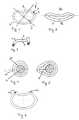
- FIG. 1is a plan view of an annular implant
- FIG. 2is a side elevation viewed from the front of the annular implant shown in FIG. 1 ,
- FIG. 3is a side elevation viewed from the side of the annular implant shown in FIG. 1 ,
- FIG. 4is a section through an annular region of the implant shown in FIG. 1 ,
- FIG. 5is a section through an annular region of the implant shown in FIG. 1 in the region of a fastening clip
- FIG. 6is a plan view of an implant corresponding to the implant shown in FIG. 1 , though with two fixing points,
- FIG. 7is a plan view of an implant with drawn-in quadrant and puncture channels
- FIG. 8is a section through the implant shown in FIG. 7 .
- FIG. 9is a view of the section shown in FIG. 8 with enclosing tissue
- FIG. 10is an alternative embodiment in section through the implant with decentralized puncture channels
- FIG. 11is another embodiment in section with a puncture channel, which is arranged offset to the imagined surface enclosed by the base,
- FIG. 12is an enlarged view of a section of a base with round puncture channels
- FIG. 13is an enlarged view of a section of a base with oval designed puncture channels.
- the implant 1 shown in FIG. 1has an annular base 2 , which encloses an imagined surface 3 .
- the side elevations shown in FIGS. 2 and 3explain that the imagined surface 3 has a bent form. In the present case it is bent in an S-shape. It therefore has opposite bent regions 4 and 5 , between which a point of inflexion 6 lies.
- FIG. 1shows that the imagined surface enclosed by the base is asymmetrical.
- the region 7 of the base 2has approximately the form of an ellipse, while the remaining peripheral region in the region 8 is bent opposite and in the region 9 is designed approximately straight.
- FIG. 4shows that the base 2 is enclosed by two material layers 10 and 11 .
- the basecomprises a metallic core material. This is enclosed by a relatively solid material 10 .
- the relatively solid material 10creates a good connection to the metallic core material 2 and is enclosed by the second layer 11 .
- the second layer 11comes into contact with the enclosing tissue and has the usual soft characteristic.
- FIG. 5shows that the implant 1 can also have a fastening clip 12 .
- This fastening clip 12is formed in the embodiment by the second layer 10 made of relatively solid material. Because the fastening clip 12 is designed such the geometrical region, in which the thread can be fixed, is enlarged. The fastening clip 12 can enclose the entire base annularly.
- FIG. 6shows an implant with two fixing points 13 and 14 .
- These fixing points 13 and 14lie to the right and left of a concave bent edge region of the annular base. These fixing points are designed such that the stress can be input centrally into a valve ring. The position of the fixing points is adapted to the anatomical conditions and should allow fixing to the Trigoni Fibrosae.
- an implantis divided into four quadrants by means of the lines 15 and 16 lying orthogonally to one another.
- the edge line of the implantis bent inwards and is thus concave, whereas the edge line of the implant is bent outwards in both the other quadrants 18 and 19 attaching thereto on the left.
- the edge line of the implantis first bent outwards, as in the quadrant lying in front, and a bend 21 is provided approximately in the centre of the fourth quadrant, which leads through to a flattened or slightly inwardly bent partial region 22 .
- This partial region 22goes as far as another bend 23 , which lies approximately at the transition from the fourth quadrant to the first quadrant.
- Provided in the base 24 of the implantare lengthy puncture channels 25 , of which a large number is arranged on the base 24 of the implant.
- the section shown in FIG. 8shows a possible embodiment of such puncture channels 25 .
- the channel 25divides the base 24 in the region of the puncture channels into two base cross-sectional areas 26 , 27 circular in cross-section.
- a funnel-shaped structure 28which facilitates a needle being inserted into the puncture channel 25 , is created due to the structuring of the base in the transition region to the puncture channel.
- the puncture channelsenable an embodiment without tissue enclosing the base. Yet also with use of tissue enclosing the base—as shown in FIG. 9 —the channel 25 facilitates the anchoring of threads on the base, as long as the threads are guided through the enclosing tissue 29 and the puncture channel 25 .
- FIGS. 10 and 11show that the puncture channels do not have to be arranged in the centre of the base. Slight offsetting of the puncture channels 30 radially outwards, as shown in FIG. 10 , enables the implant to be sewn into its radial outer region.
- FIG. 11shows a puncture channel 31 , in which the outer part 32 of the base is arranged offset to the imagined surface 33 enclosed by the base. This facilitates the implant to be sewn onto the surrounding tissue.
- the puncture channelscan be designed as round openings 34 or as oval openings 35 .
- the oval openings 35extend in a longitudinal direction of the base so as to impair the stability of the base minimally only.
- the base in the plan viewis designed bean-shaped with a flattened side.
- the complex interplay enclosing the base of concave and convex linescorresponds substantially to the outer contour of a bean, whereby a flattened surface or another shorter surface bent inwards is provided attached to the inwards bent surface.
- the embodimentsshow implants, which are designed for use as a valve ring. Implants according to the present invention can however be used for different applications in surgery and in particular for strengthening outlets and vessels.
Landscapes
- Health & Medical Sciences (AREA)
- Cardiology (AREA)
- Oral & Maxillofacial Surgery (AREA)
- Transplantation (AREA)
- Engineering & Computer Science (AREA)
- Biomedical Technology (AREA)
- Heart & Thoracic Surgery (AREA)
- Vascular Medicine (AREA)
- Life Sciences & Earth Sciences (AREA)
- Animal Behavior & Ethology (AREA)
- General Health & Medical Sciences (AREA)
- Public Health (AREA)
- Veterinary Medicine (AREA)
- Prostheses (AREA)
Abstract
Description
Claims (1)
Priority Applications (1)
| Application Number | Priority Date | Filing Date | Title |
|---|---|---|---|
| US11/897,223US7758638B2 (en) | 2004-07-13 | 2007-08-29 | Implant with an annular base |
Applications Claiming Priority (2)
| Application Number | Priority Date | Filing Date | Title |
|---|---|---|---|
| US10/890,032US7276079B2 (en) | 2003-01-13 | 2004-07-13 | Implant with an annular base |
| US11/897,223US7758638B2 (en) | 2004-07-13 | 2007-08-29 | Implant with an annular base |
Related Parent Applications (1)
| Application Number | Title | Priority Date | Filing Date |
|---|---|---|---|
| US10/890,032ContinuationUS7276079B2 (en) | 2003-01-13 | 2004-07-13 | Implant with an annular base |
Publications (2)
| Publication Number | Publication Date |
|---|---|
| US20080009941A1 US20080009941A1 (en) | 2008-01-10 |
| US7758638B2true US7758638B2 (en) | 2010-07-20 |
Family
ID=38920034
Family Applications (1)
| Application Number | Title | Priority Date | Filing Date |
|---|---|---|---|
| US11/897,223Expired - LifetimeUS7758638B2 (en) | 2004-07-13 | 2007-08-29 | Implant with an annular base |
Country Status (1)
| Country | Link |
|---|---|
| US (1) | US7758638B2 (en) |
Cited By (4)
| Publication number | Priority date | Publication date | Assignee | Title |
|---|---|---|---|---|
| USD642683S1 (en)* | 2009-12-02 | 2011-08-02 | Drake Daniel H | Annuloplasty ring |
| USD642684S1 (en)* | 2009-12-02 | 2011-08-02 | Drake Daniel H | Annuloplasty ring |
| USD676133S1 (en)* | 2009-12-02 | 2013-02-12 | Daniel H. Drake | Annuloplasty ring |
| US11851221B2 (en) | 2022-04-21 | 2023-12-26 | Curium Us Llc | Systems and methods for producing a radioactive drug product using a dispensing unit |
Families Citing this family (1)
| Publication number | Priority date | Publication date | Assignee | Title |
|---|---|---|---|---|
| ITTO20100544A1 (en)* | 2010-06-23 | 2011-12-24 | Enrico Pasquino | PROSTHESIS FOR CARDIAC VALVES WITH VARIABLE RIGIDITY IN TIME. |
Citations (26)
| Publication number | Priority date | Publication date | Assignee | Title |
|---|---|---|---|---|
| US3656185A (en) | 1969-02-04 | 1972-04-18 | Rhone Poulenc Sa | Cardiac valvular support prosthesis |
| US4055861A (en) | 1975-04-11 | 1977-11-01 | Rhone-Poulenc Industries | Support for a natural human heart valve |
| US4164046A (en) | 1977-05-16 | 1979-08-14 | Cooley Denton | Valve prosthesis |
| US5061277A (en) | 1986-08-06 | 1991-10-29 | Baxter International Inc. | Flexible cardiac valvular support prosthesis |
| US5104407A (en) | 1989-02-13 | 1992-04-14 | Baxter International Inc. | Selectively flexible annuloplasty ring |
| US5171252A (en)* | 1991-02-05 | 1992-12-15 | Friedland Thomas W | Surgical fastening clip formed of a shape memory alloy, a method of making such a clip and a method of using such a clip |
| US5439479A (en)* | 1990-12-20 | 1995-08-08 | United States Surigcal Corporation | Surgical clip |
| WO1997016135A1 (en) | 1995-11-01 | 1997-05-09 | St. Jude Medical, Inc. | Bioresorbable annuloplasty prosthesis |
| DE69403482T2 (en) | 1993-08-03 | 1997-12-11 | Seguin, Jacques, Montpellier | RING PROSTHESIS FOR HEART SURGERY |
| US5810882A (en)* | 1994-08-05 | 1998-09-22 | Origin Medsystems, Inc. | Surgical helical fastener with applicator and method of use |
| WO1999049817A1 (en) | 1998-03-31 | 1999-10-07 | Shelhigh, Inc. | Natural tissue heart valve prosthesis |
| EP1034753A1 (en) | 1999-03-09 | 2000-09-13 | Jostra AG | Annuloplasty ring |
| WO2000062715A1 (en) | 1999-04-16 | 2000-10-26 | Edwards Lifesciences Corporation | Aortic annuloplasty ring |
| US6183512B1 (en)* | 1999-04-16 | 2001-02-06 | Edwards Lifesciences Corporation | Flexible annuloplasty system |
| US20020055773A1 (en) | 1999-07-12 | 2002-05-09 | Louis A. Campbell | Polymer heart valve with insert molded fabric sewing cuff |
| EP1258232A2 (en) | 2001-05-17 | 2002-11-20 | Ottavio Alfieri | Annular prosthesis for mitral valve |
| US20030093148A1 (en) | 2001-11-13 | 2003-05-15 | Bolling Steven F. | Mitral valve annuloplasty ring for molding left ventricle geometry |
| WO2003053289A1 (en) | 2001-12-21 | 2003-07-03 | Simcha Milo | Implantation system for annuloplasty rings |
| EP1348406A1 (en) | 2002-03-27 | 2003-10-01 | SORIN BIOMEDICA CARDIO S.p.A. | A prosthesis for annuloplasty comprising a perforated element |
| US20030208264A1 (en) | 2001-08-28 | 2003-11-06 | Mccarthy Patrick M. | Three-dimensional annuloplasty ring and template |
| US20040006384A1 (en) | 2002-07-08 | 2004-01-08 | Mccarthy Patrick | Mitral valve annuluplasty ring having a posterior bow |
| US6955689B2 (en)* | 2001-03-15 | 2005-10-18 | Medtronic, Inc. | Annuloplasty band and method |
| US20060129236A1 (en) | 2004-04-29 | 2006-06-15 | Mccarthy Patrick M | Annuloplasty ring for mitral valve prolapse |
| US7294148B2 (en)* | 2004-04-29 | 2007-11-13 | Edwards Lifesciences Corporation | Annuloplasty ring for mitral valve prolapse |
| US20080058924A1 (en)* | 2006-09-01 | 2008-03-06 | Aaron Ingle | Saddle-shaped annuloplasty ring |
| US20080154359A1 (en)* | 2001-11-01 | 2008-06-26 | Salgo Ivan S | Non-planar cardiac vascular support prosthesis |
- 2007
- 2007-08-29USUS11/897,223patent/US7758638B2/ennot_activeExpired - Lifetime
Patent Citations (34)
| Publication number | Priority date | Publication date | Assignee | Title |
|---|---|---|---|---|
| US3656185A (en) | 1969-02-04 | 1972-04-18 | Rhone Poulenc Sa | Cardiac valvular support prosthesis |
| US4055861A (en) | 1975-04-11 | 1977-11-01 | Rhone-Poulenc Industries | Support for a natural human heart valve |
| US4164046A (en) | 1977-05-16 | 1979-08-14 | Cooley Denton | Valve prosthesis |
| US5061277A (en) | 1986-08-06 | 1991-10-29 | Baxter International Inc. | Flexible cardiac valvular support prosthesis |
| US5061277B1 (en) | 1986-08-06 | 2000-02-29 | Baxter Travenol Lab | Flexible cardiac valvular support prosthesis |
| US5104407B1 (en) | 1989-02-13 | 1999-09-21 | Baxter Int | Selectively flexible annuloplasty ring |
| US5104407A (en) | 1989-02-13 | 1992-04-14 | Baxter International Inc. | Selectively flexible annuloplasty ring |
| DE69033195T2 (en) | 1989-02-13 | 2000-03-09 | Baxter International Inc. | Ring prosthesis for anuloplasty |
| US5439479A (en)* | 1990-12-20 | 1995-08-08 | United States Surigcal Corporation | Surgical clip |
| US5171252A (en)* | 1991-02-05 | 1992-12-15 | Friedland Thomas W | Surgical fastening clip formed of a shape memory alloy, a method of making such a clip and a method of using such a clip |
| DE69403482T2 (en) | 1993-08-03 | 1997-12-11 | Seguin, Jacques, Montpellier | RING PROSTHESIS FOR HEART SURGERY |
| US5810882A (en)* | 1994-08-05 | 1998-09-22 | Origin Medsystems, Inc. | Surgical helical fastener with applicator and method of use |
| WO1997016135A1 (en) | 1995-11-01 | 1997-05-09 | St. Jude Medical, Inc. | Bioresorbable annuloplasty prosthesis |
| WO1999049817A1 (en) | 1998-03-31 | 1999-10-07 | Shelhigh, Inc. | Natural tissue heart valve prosthesis |
| EP1034753A1 (en) | 1999-03-09 | 2000-09-13 | Jostra AG | Annuloplasty ring |
| US6183512B1 (en)* | 1999-04-16 | 2001-02-06 | Edwards Lifesciences Corporation | Flexible annuloplasty system |
| US6231602B1 (en) | 1999-04-16 | 2001-05-15 | Edwards Lifesciences Corporation | Aortic annuloplasty ring |
| WO2000062715A1 (en) | 1999-04-16 | 2000-10-26 | Edwards Lifesciences Corporation | Aortic annuloplasty ring |
| US20020055773A1 (en) | 1999-07-12 | 2002-05-09 | Louis A. Campbell | Polymer heart valve with insert molded fabric sewing cuff |
| US6955689B2 (en)* | 2001-03-15 | 2005-10-18 | Medtronic, Inc. | Annuloplasty band and method |
| US6726717B2 (en) | 2001-05-17 | 2004-04-27 | Edwards Lifesciences Corporation | Annular prosthesis for mitral valve |
| EP1258232A2 (en) | 2001-05-17 | 2002-11-20 | Ottavio Alfieri | Annular prosthesis for mitral valve |
| US20030208264A1 (en) | 2001-08-28 | 2003-11-06 | Mccarthy Patrick M. | Three-dimensional annuloplasty ring and template |
| US20080154359A1 (en)* | 2001-11-01 | 2008-06-26 | Salgo Ivan S | Non-planar cardiac vascular support prosthesis |
| US20030093148A1 (en) | 2001-11-13 | 2003-05-15 | Bolling Steven F. | Mitral valve annuloplasty ring for molding left ventricle geometry |
| US6805710B2 (en)* | 2001-11-13 | 2004-10-19 | Edwards Lifesciences Corporation | Mitral valve annuloplasty ring for molding left ventricle geometry |
| US7329280B2 (en)* | 2001-11-13 | 2008-02-12 | Edwards Lifesciences Corp. | Methods of implanting a mitral valve annuloplasty ring to correct mitral regurgitation |
| WO2003053289A1 (en) | 2001-12-21 | 2003-07-03 | Simcha Milo | Implantation system for annuloplasty rings |
| EP1348406A1 (en) | 2002-03-27 | 2003-10-01 | SORIN BIOMEDICA CARDIO S.p.A. | A prosthesis for annuloplasty comprising a perforated element |
| US20040006384A1 (en) | 2002-07-08 | 2004-01-08 | Mccarthy Patrick | Mitral valve annuluplasty ring having a posterior bow |
| US6858039B2 (en) | 2002-07-08 | 2005-02-22 | Edwards Lifesciences Corporation | Mitral valve annuloplasty ring having a posterior bow |
| US20060129236A1 (en) | 2004-04-29 | 2006-06-15 | Mccarthy Patrick M | Annuloplasty ring for mitral valve prolapse |
| US7294148B2 (en)* | 2004-04-29 | 2007-11-13 | Edwards Lifesciences Corporation | Annuloplasty ring for mitral valve prolapse |
| US20080058924A1 (en)* | 2006-09-01 | 2008-03-06 | Aaron Ingle | Saddle-shaped annuloplasty ring |
Non-Patent Citations (1)
| Title |
|---|
| German Priority Application Search Report. |
Cited By (5)
| Publication number | Priority date | Publication date | Assignee | Title |
|---|---|---|---|---|
| USD642683S1 (en)* | 2009-12-02 | 2011-08-02 | Drake Daniel H | Annuloplasty ring |
| USD642684S1 (en)* | 2009-12-02 | 2011-08-02 | Drake Daniel H | Annuloplasty ring |
| USD676133S1 (en)* | 2009-12-02 | 2013-02-12 | Daniel H. Drake | Annuloplasty ring |
| US11851221B2 (en) | 2022-04-21 | 2023-12-26 | Curium Us Llc | Systems and methods for producing a radioactive drug product using a dispensing unit |
| US12428177B2 (en) | 2022-04-21 | 2025-09-30 | Curium Us Llc | Systems and methods for producing a radioactive drug product using a dispensing unit |
Also Published As
| Publication number | Publication date |
|---|---|
| US20080009941A1 (en) | 2008-01-10 |
Similar Documents
| Publication | Publication Date | Title |
|---|---|---|
| US12279955B2 (en) | Mitral or tricuspid repair systems with multi-directional anchors | |
| CN115024861B (en) | Prosthetic valve with mechanically coupled leaflets | |
| JP4174184B2 (en) | Aortic annuloplasty ring | |
| US6197054B1 (en) | Sutureless cuff for heart valves | |
| US9289294B2 (en) | Heart valve annuloplasty prosthesis sewing cuffs and methods of making same | |
| US6602289B1 (en) | Annuloplasty rings of particular use in surgery for the mitral valve | |
| CA2941121C (en) | Cardiac stent-valve and delivery device for such a valve | |
| CN106999280B (en) | Bioprosthetic heart valve | |
| JP5685560B2 (en) | Prosthesis adapted for implantation of two-piece heart valves | |
| US3197788A (en) | Prosthetic valve for cardiac surgery | |
| US7276079B2 (en) | Implant with an annular base | |
| US7179290B2 (en) | Flexible heart valve | |
| US6217611B1 (en) | Modular heart valve prothesis | |
| EP2713955B1 (en) | Heart valve sewing cuff | |
| US7758638B2 (en) | Implant with an annular base | |
| JP2008535572A (en) | Connecting band and stress-absorbing frame for highly flexible heart valves | |
| JP2022527076A (en) | Artificial heart valve | |
| EP0257874A1 (en) | Flexible cardiac valvular support prosthesis | |
| EP0108941A2 (en) | A low-profile biological bicuspid valve | |
| CZ237093A3 (en) | Supporting element from plastic material used for the replacement of a heart valve | |
| CN1610529A (en) | Methods and devices for heart valve therapy | |
| JP2023540252A (en) | artificial heart valve | |
| EP3801393A1 (en) | Circumferentially constrictive annuloplasty ring | |
| JP2023163879A (en) | Fixing structure | |
| US20030204250A1 (en) | Heart valve |
Legal Events
| Date | Code | Title | Description |
|---|---|---|---|
| AS | Assignment | Owner name:SIEVERS, HANS HINRICH, GERMANY Free format text:TRANSFER LETTER AGREEMENT;ASSIGNOR:MEDOS MEDIZINTECHNIK AG;REEL/FRAME:019880/0961 Effective date:20041021 | |
| AS | Assignment | Owner name:ATS MEDICAL, INC., MINNESOTA Free format text:ASSIGNMENT OF ASSIGNORS INTEREST;ASSIGNOR:SIEVERS, HANS;REEL/FRAME:022597/0622 Effective date:20081006 | |
| STCF | Information on status: patent grant | Free format text:PATENTED CASE | |
| FEPP | Fee payment procedure | Free format text:PAT HOLDER NO LONGER CLAIMS SMALL ENTITY STATUS, ENTITY STATUS SET TO UNDISCOUNTED (ORIGINAL EVENT CODE: STOL); ENTITY STATUS OF PATENT OWNER: LARGE ENTITY | |
| AS | Assignment | Owner name:MEDTRONIC ATS MEDICAL INC., MINNESOTA Free format text:MERGER;ASSIGNORS:ATS MEDICAL INC;PILGRIM MERGER CORPORATION;REEL/FRAME:026064/0197 Effective date:20100812 | |
| FPAY | Fee payment | Year of fee payment:4 | |
| MAFP | Maintenance fee payment | Free format text:PAYMENT OF MAINTENANCE FEE, 8TH YEAR, LARGE ENTITY (ORIGINAL EVENT CODE: M1552) Year of fee payment:8 | |
| AS | Assignment | Owner name:MEDTRONIC ATS MEDICAL, INC., MINNESOTA Free format text:MERGER AND CHANGE OF NAME;ASSIGNORS:ATS MEDICAL, INC.;PILGRIM MERGER CORPORATION;REEL/FRAME:056821/0401 Effective date:20100812 | |
| MAFP | Maintenance fee payment | Free format text:PAYMENT OF MAINTENANCE FEE, 12TH YEAR, LARGE ENTITY (ORIGINAL EVENT CODE: M1553); ENTITY STATUS OF PATENT OWNER: LARGE ENTITY Year of fee payment:12 |