US7758229B2 - Light source assembly and backlight module having the same - Google Patents
Light source assembly and backlight module having the sameDownload PDFInfo
- Publication number
- US7758229B2 US7758229B2US11/972,501US97250108AUS7758229B2US 7758229 B2US7758229 B2US 7758229B2US 97250108 AUS97250108 AUS 97250108AUS 7758229 B2US7758229 B2US 7758229B2
- Authority
- US
- United States
- Prior art keywords
- light
- light source
- guide plate
- filling layer
- transparent filling
- Prior art date
- Legal status (The legal status is an assumption and is not a legal conclusion. Google has not performed a legal analysis and makes no representation as to the accuracy of the status listed.)
- Expired - Fee Related, expires
Links
Images


Classifications
- G—PHYSICS
- G02—OPTICS
- G02B—OPTICAL ELEMENTS, SYSTEMS OR APPARATUS
- G02B6/00—Light guides; Structural details of arrangements comprising light guides and other optical elements, e.g. couplings
- G02B6/0001—Light guides; Structural details of arrangements comprising light guides and other optical elements, e.g. couplings specially adapted for lighting devices or systems
- G02B6/0011—Light guides; Structural details of arrangements comprising light guides and other optical elements, e.g. couplings specially adapted for lighting devices or systems the light guides being planar or of plate-like form
- G02B6/0013—Means for improving the coupling-in of light from the light source into the light guide
- G02B6/0023—Means for improving the coupling-in of light from the light source into the light guide provided by one optical element, or plurality thereof, placed between the light guide and the light source, or around the light source
- G02B6/0026—Wavelength selective element, sheet or layer, e.g. filter or grating
- G—PHYSICS
- G02—OPTICS
- G02B—OPTICAL ELEMENTS, SYSTEMS OR APPARATUS
- G02B6/00—Light guides; Structural details of arrangements comprising light guides and other optical elements, e.g. couplings
- G02B6/0001—Light guides; Structural details of arrangements comprising light guides and other optical elements, e.g. couplings specially adapted for lighting devices or systems
- G02B6/0011—Light guides; Structural details of arrangements comprising light guides and other optical elements, e.g. couplings specially adapted for lighting devices or systems the light guides being planar or of plate-like form
- G02B6/0013—Means for improving the coupling-in of light from the light source into the light guide
- G02B6/0023—Means for improving the coupling-in of light from the light source into the light guide provided by one optical element, or plurality thereof, placed between the light guide and the light source, or around the light source
- G02B6/003—Lens or lenticular sheet or layer
- H—ELECTRICITY
- H10—SEMICONDUCTOR DEVICES; ELECTRIC SOLID-STATE DEVICES NOT OTHERWISE PROVIDED FOR
- H10H—INORGANIC LIGHT-EMITTING SEMICONDUCTOR DEVICES HAVING POTENTIAL BARRIERS
- H10H20/00—Individual inorganic light-emitting semiconductor devices having potential barriers, e.g. light-emitting diodes [LED]
- H10H20/80—Constructional details
- H10H20/85—Packages
- H10H20/855—Optical field-shaping means, e.g. lenses
Definitions
- the inventiongenerally relates to light source assembly, and particularly to a light source assembly with an improved efficiency of light utilization.
- a backlight modulegenerally includes a light source and a light guide plate.
- the light sourcecan be, for example, light-emitting diodes (LEDs), and cold cathode fluorescent lamps (CCFL).
- the light sourceis usually mounted in a side or bottom of the light guide plate.
- an air gapexists between the light source and the light guide plate.
- the refractive index of the light guide plate of the light sourceis greater than the air.
- the light guide plateis in direct contact with the light source.
- the material of the light guide plate and the bezel of the light sourceboth are solid material, therefore a plurality of small gaps may exist in the interface, however, and the plurality of small gaps may cause interference.
- the light source assemblyincludes at least one light source, at least one light guide plate and a transparent filling layer.
- the at least one light sourcehas a light-emitting layer.
- the transparent filling layeris interposed between the light-source and the light guide plate. The light source assembly can reduce reflection and refraction loss when the light beam enters the light guide plate.
- FIG. 1is a schematic view of a light source assembly with a transparent filling layer in accordance with a first embodiment of the present invention.
- FIG. 2is a schematic view of a light source assembly with a hemispherical convex structure of the light-emitting layer in accordance with a second embodiment of the second invention.
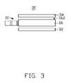
- FIG. 3is a schematic view of a light source assembly with a edge lighting backlight module in accordance with a third embodiment.
- the light source assembly 10includes a light source 12 , a transparent filling layer 14 and a light guide plate 16 .
- the light source 12is a solid-state light source (e.g. LED).
- the light source 12has a light-emitting layer 122 and a light-pervious cover 124 .
- the light-pervious cover 124is attached on the light emitting layer 122 .
- the transparent filling layer 14is interposed between the light source 12 and the light guide plate 16 .
- the light-emitting layer 122may be an encapsulation enclosure of the light source 12 or a light-extracting structure of the encapsulation enclosure of the light source 12 .
- the light-emitting layer 122may be made of high transparency material such as glass, silicone, transparent silicone rubber and transparent polyurethane.
- the thickness of the transparent filling layer 14may be just thick enough to be interposed between the light-pervious cover 124 and the light guide plate 16 .
- the transparent filling layer 14may be made of soft transparent material, such as silicone, transparent silicone rubber, thermoplastic polyurethane, polyvinyl chloride, and high viscous liquid such as organic silicone oil, higher alcohols and esters compounds. The carbon atom of the higher alcohols is greater than five.
- the light guide plate 16may be transparent plate or wedge plate.
- the material of the light guide plate 16may be glass, polyacrylate and polymethacrylate.
- the refractive index of the light-emitting layer n Lis equal to or less than the refractive index of the transparent filling layer n F
- the refractive index of the transparent filling layer n Fis equal to or less than the refractive index of the light guide plate.
- the refractive index of the light-emitting layer 122 , the transparent filling layer 14 and the light guide plate 16are substantially the same. Thus, the reflection and refraction loss are reduced when the light beam enters the light guide plate 16 .
- n F⁇ square root over (n L ⁇ n G ) ⁇ .
- a plurality of fluorescent powdermay be mixed in the transparent filling layer 14 .
- the light of the light-emitting layer 122can stimulate the fluorescent powder when the light beam enters the transparent filling layer 14 , thereby a large divergent angle and improved light uniformity can be achieved.
- the transparent filling layer 14may be in contact with the light-emitting layer 122 prior to assembling of the light source assembly 10 .
- the transparent filling layer 14may be in contact with the light guide plate 16 prior to assembling the light source assembly 10 .
- the transparent filling layer 14may be divided into a first portion and a second portion. The first portion is coming into contact with the light-pervious cover 124 of the light source 12 , and the second portion is coming into contact with the light guide plate 16 . If the material of the transparent filling layer 14 and the light-pervious cover 124 are the same, the transparent filling layer 14 and the light-pervious cover 124 of the light source 12 may be integrally formed. When the light source 12 and the light guide plate 16 are assembled together, the transparent filling layer 14 is interposed between the light source 12 and the light guide plate 16 .
- the transparent filling layer 14is interposed between the light source 12 and the light guide plate 16 can reduce reflection and refraction loss when the light beam enters the light guide plate 16 .
- a large divergent angle and improved light uniformitymay be achieved. If the refractive index of the light-emitting layer 122 , the transparent filling layer 14 and the light guide plate 16 are the same or similar, the advantages of the light source assembly are more significant.
- FIG. 2illustrates a light source assembly 20 of a second embodiment.
- the light-emitting layer 222 and the light-pervious cover 224have a hemispherical convex structure.
- the light guide plate 26has a hemispherical concave recess 262 .
- the light-emitting layer 222is accommodated in the concave recess 262 .
- the transparent filling layer 24is interposed between the light source 12 and the light guide plate 226 .
- the hemispherical light-emitting layer 222has a large divergent angle and improved distribution of the optical field.
- the light beam of the light-emitting layer 222enters the light guide plate 26 with higher efficiency of utilization.
- the shape of the light-emitting layer 222may be hemispherical, circle, rhombus and taper structure.
- FIG. 3illustrates an edge lighting backlight module 30 having a light source assembly 10 , a reflective plate 32 and a light diffusing sheet 34 .
- the light diffusing sheet 34disposed on a light-extracting surface 162 of the light guide plate 16 .
- the reflective plate 32is disposed on an opposite side of the light guide plate 16 .
- the reflective plate 32is configured for reflecting the light exiting from the light guide plate 16 back into the light guide plate 16 .
- the light exiting the light guide plate 16is enters the light diffusing sheet 34 .
- the backlight module 30may be an edge lighting backlight module or bottom lighting backlight module.
Landscapes
- Physics & Mathematics (AREA)
- General Physics & Mathematics (AREA)
- Optics & Photonics (AREA)
- Planar Illumination Modules (AREA)
Abstract
Description
Claims (15)
nF=√{square root over (nL×nG)}.
nF=√{square root over (nL×nG)}; and
Applications Claiming Priority (3)
| Application Number | Priority Date | Filing Date | Title |
|---|---|---|---|
| CN2007100748065ACN101315484B (en) | 2007-06-01 | 2007-06-01 | Light source component and back light module unit including the same |
| CN200710074806.5 | 2007-06-01 | ||
| CN200710074806 | 2007-06-01 |
Publications (2)
| Publication Number | Publication Date |
|---|---|
| US20080298067A1 US20080298067A1 (en) | 2008-12-04 |
| US7758229B2true US7758229B2 (en) | 2010-07-20 |
Family
ID=39705223
Family Applications (1)
| Application Number | Title | Priority Date | Filing Date |
|---|---|---|---|
| US11/972,501Expired - Fee RelatedUS7758229B2 (en) | 2007-06-01 | 2008-01-10 | Light source assembly and backlight module having the same |
Country Status (3)
| Country | Link |
|---|---|
| US (1) | US7758229B2 (en) |
| EP (1) | EP1998103A1 (en) |
| CN (1) | CN101315484B (en) |
Cited By (2)
| Publication number | Priority date | Publication date | Assignee | Title |
|---|---|---|---|---|
| US20100002465A1 (en)* | 2008-07-07 | 2010-01-07 | Advanced Optoelectronic Technology Inc. | Light emitting diode device and backlight module using the same |
| US20130070481A1 (en)* | 2011-09-20 | 2013-03-21 | Toyoda Gosei Co., Ltd. | Linear light source apparatus |
Families Citing this family (16)
| Publication number | Priority date | Publication date | Assignee | Title |
|---|---|---|---|---|
| DE202009018087U1 (en)* | 2009-04-30 | 2011-02-03 | Saint-Gobain Sekurit Deutschland Gmbh & Co. Kg | disk assembly |
| KR101738072B1 (en)* | 2010-09-10 | 2017-05-30 | 삼성디스플레이 주식회사 | Light guide module, method of manufacturing thereof and backlight assembly having the same |
| CN104421681A (en)* | 2013-08-26 | 2015-03-18 | 展晶科技(深圳)有限公司 | LED (Light Emitting Diode) light source module |
| CN103791455B (en) | 2014-02-14 | 2017-12-08 | 京东方科技集团股份有限公司 | Side backlight module and preparation method thereof, display device |
| US9829617B2 (en) | 2014-11-10 | 2017-11-28 | Light Polymers Holding | Polymer-small molecule film or coating having reverse or flat dispersion of retardation |
| US9856172B2 (en) | 2015-08-25 | 2018-01-02 | Light Polymers Holding | Concrete formulation and methods of making |
| WO2017084511A1 (en)* | 2015-11-22 | 2017-05-26 | 李荣亮 | Led guardrail tube |
| CN205374943U (en)* | 2016-02-03 | 2016-07-06 | 北京京东方显示技术有限公司 | Backlight module and display device |
| CN106855207A (en)* | 2017-02-28 | 2017-06-16 | 东莞市百分百科技有限公司 | A kind of LED blackboard lightses of high brightness and high evenness |
| CN106895278A (en)* | 2017-03-20 | 2017-06-27 | 京东方科技集团股份有限公司 | A kind of preparation method of LED, backlight module, display device and backlight module |
| DE102017208066A1 (en)* | 2017-05-12 | 2018-11-15 | Osram Gmbh | LAMP AND METHOD FOR ITS MANUFACTURE |
| US10962696B2 (en) | 2018-01-31 | 2021-03-30 | Light Polymers Holding | Coatable grey polarizer |
| US11370914B2 (en) | 2018-07-24 | 2022-06-28 | Light Polymers Holding | Methods of forming polymeric polarizers from lyotropic liquid crystals and polymeric polarizers formed thereby |
| CN110906272B (en)* | 2018-09-14 | 2021-11-16 | 深圳市绎立锐光科技开发有限公司 | Light source device and car light |
| CN115885209B (en)* | 2021-05-19 | 2024-10-15 | 京东方科技集团股份有限公司 | Backlight module, display device and manufacturing method |
| US12072520B2 (en) | 2021-11-11 | 2024-08-27 | Light Polymers Holding | Linear polarizers and methods of forming a linear polarizer |
Citations (7)
| Publication number | Priority date | Publication date | Assignee | Title |
|---|---|---|---|---|
| US6036328A (en)* | 1995-05-23 | 2000-03-14 | Sharp Kabushiki Kaisha | Plane-shaped lighting device and a display using such a device |
| US20040080926A1 (en) | 2002-10-23 | 2004-04-29 | Hannstar Display Corp. | Polarized light source device and back light module for liquid crystal display |
| US20050107499A1 (en)* | 2003-11-14 | 2005-05-19 | Georgeau Philip C. | Moisture curable sealer and adhesive composition |
| US20060072339A1 (en)* | 2004-10-01 | 2006-04-06 | Hsiao-I Li | Backlight module |
| US20070081360A1 (en) | 2005-06-28 | 2007-04-12 | Edward Bailey | Display backlight with improved light coupling and mixing |
| US7481558B2 (en)* | 2007-01-09 | 2009-01-27 | Bright View Electronics Co., Ltd. | Lateral light emitting apparatus |
| US7534025B2 (en)* | 2006-08-25 | 2009-05-19 | Philips Lumiled Lighting Company, Llc | Thin backlight with flipped light emitting diode |
Family Cites Families (6)
| Publication number | Priority date | Publication date | Assignee | Title |
|---|---|---|---|---|
| US5980054A (en)* | 1996-05-09 | 1999-11-09 | Matsushita Electric Industrial Co., Ltd. | Panel-form illuminating system |
| DE19918370B4 (en)* | 1999-04-22 | 2006-06-08 | Osram Opto Semiconductors Gmbh | LED white light source with lens |
| US6871973B2 (en)* | 2002-11-25 | 2005-03-29 | Toppoly Optoelectronics Corp. | Light module for LCD panel |
| TW200527015A (en)* | 2003-12-25 | 2005-08-16 | Sumitomo Chemical Co | Light guide plate, back light and liquid crystal display device |
| KR20050107033A (en)* | 2004-05-07 | 2005-11-11 | 삼성전자주식회사 | A light emitting diode module and a liquid crystal display provided with the same |
| CN100396715C (en)* | 2006-04-17 | 2008-06-25 | 广州天赐有机硅科技有限公司 | Branched benzene siliconic oil |
- 2007
- 2007-06-01CNCN2007100748065Apatent/CN101315484B/ennot_activeExpired - Fee Related
- 2008
- 2008-01-10USUS11/972,501patent/US7758229B2/ennot_activeExpired - Fee Related
- 2008-05-28EPEP08251857Apatent/EP1998103A1/ennot_activeWithdrawn
Patent Citations (7)
| Publication number | Priority date | Publication date | Assignee | Title |
|---|---|---|---|---|
| US6036328A (en)* | 1995-05-23 | 2000-03-14 | Sharp Kabushiki Kaisha | Plane-shaped lighting device and a display using such a device |
| US20040080926A1 (en) | 2002-10-23 | 2004-04-29 | Hannstar Display Corp. | Polarized light source device and back light module for liquid crystal display |
| US20050107499A1 (en)* | 2003-11-14 | 2005-05-19 | Georgeau Philip C. | Moisture curable sealer and adhesive composition |
| US20060072339A1 (en)* | 2004-10-01 | 2006-04-06 | Hsiao-I Li | Backlight module |
| US20070081360A1 (en) | 2005-06-28 | 2007-04-12 | Edward Bailey | Display backlight with improved light coupling and mixing |
| US7534025B2 (en)* | 2006-08-25 | 2009-05-19 | Philips Lumiled Lighting Company, Llc | Thin backlight with flipped light emitting diode |
| US7481558B2 (en)* | 2007-01-09 | 2009-01-27 | Bright View Electronics Co., Ltd. | Lateral light emitting apparatus |
Cited By (2)
| Publication number | Priority date | Publication date | Assignee | Title |
|---|---|---|---|---|
| US20100002465A1 (en)* | 2008-07-07 | 2010-01-07 | Advanced Optoelectronic Technology Inc. | Light emitting diode device and backlight module using the same |
| US20130070481A1 (en)* | 2011-09-20 | 2013-03-21 | Toyoda Gosei Co., Ltd. | Linear light source apparatus |
Also Published As
| Publication number | Publication date |
|---|---|
| CN101315484B (en) | 2011-09-28 |
| US20080298067A1 (en) | 2008-12-04 |
| EP1998103A1 (en) | 2008-12-03 |
| CN101315484A (en) | 2008-12-03 |
Similar Documents
| Publication | Publication Date | Title |
|---|---|---|
| US7758229B2 (en) | Light source assembly and backlight module having the same | |
| US8641219B1 (en) | High efficiency rear lit waveguide | |
| CN101382698B (en) | Backlight module unit | |
| US7859614B2 (en) | Light emitting diode package having dual lens structure and backlight for liquid crystal display device implementing the same | |
| US9638956B2 (en) | Backlight unit and display apparatus thereof | |
| US20210116758A1 (en) | Backlight module and display device | |
| US9329323B2 (en) | Light source and backlight module having the same | |
| US9488863B2 (en) | Lighting device | |
| JP2008053013A (en) | Backlight device, and liquid crystal display device | |
| TW200909931A (en) | Backlight module and liquid crystal display using the same | |
| US20070047219A1 (en) | Direct-lit backlight having light sources with bifunctional diverters | |
| KR20190021522A (en) | Light guide plate and backlight unit having the same | |
| US20090303414A1 (en) | Optical member with a scatter layer, and backlight assembly and display device having the same | |
| CN101418930A (en) | Area source device for LED | |
| US20050088838A1 (en) | Light guiding device with two opposite light emitting surfaces and backlight module using the same | |
| CN100394272C (en) | liquid crystal display device | |
| US20190064595A1 (en) | Display system | |
| US20060120107A1 (en) | LED backlight module | |
| TWI392125B (en) | Illuminating device | |
| TWI358004B (en) | Backlight module | |
| US20110051248A1 (en) | Hybrid Optical Film | |
| KR20230116116A (en) | Backlight unit using LED chip | |
| CN210776108U (en) | Lens for television backlight module | |
| KR101948136B1 (en) | Backlight unit and display device including the same | |
| US8814413B2 (en) | Backlight module and liquid crystal display using the same |
Legal Events
| Date | Code | Title | Description |
|---|---|---|---|
| AS | Assignment | Owner name:FOXSEMICON INTEGRATED TECHNOLOGY, INC., TAIWAN Free format text:ASSIGNMENT OF ASSIGNORS INTEREST;ASSIGNOR:CHU, YUAN-FA;REEL/FRAME:020426/0115 Effective date:20071226 | |
| REMI | Maintenance fee reminder mailed | ||
| FPAY | Fee payment | Year of fee payment:4 | |
| SULP | Surcharge for late payment | ||
| AS | Assignment | Owner name:KONINKLIJKE PHILIPS N.V., NETHERLANDS Free format text:ASSIGNMENT OF ASSIGNORS INTEREST;ASSIGNOR:FOXSEMICON INTEGRATED TECHNOLOGY, INC.;REEL/FRAME:034937/0686 Effective date:20141220 | |
| AS | Assignment | Owner name:PHILIPS LIGHTING HOLDING B.V., NETHERLANDS Free format text:ASSIGNMENT OF ASSIGNORS INTEREST;ASSIGNOR:KONINKLIJKE PHILIPS N.V.;REEL/FRAME:040060/0009 Effective date:20160607 | |
| FEPP | Fee payment procedure | Free format text:MAINTENANCE FEE REMINDER MAILED (ORIGINAL EVENT CODE: REM.) | |
| LAPS | Lapse for failure to pay maintenance fees | Free format text:PATENT EXPIRED FOR FAILURE TO PAY MAINTENANCE FEES (ORIGINAL EVENT CODE: EXP.); ENTITY STATUS OF PATENT OWNER: LARGE ENTITY | |
| STCH | Information on status: patent discontinuation | Free format text:PATENT EXPIRED DUE TO NONPAYMENT OF MAINTENANCE FEES UNDER 37 CFR 1.362 | |
| FP | Lapsed due to failure to pay maintenance fee | Effective date:20180720 |