US7758056B2 - Suspension assembly with coaxial torsion bar - Google Patents
Suspension assembly with coaxial torsion barDownload PDFInfo
- Publication number
- US7758056B2 US7758056B2US12/117,283US11728308AUS7758056B2US 7758056 B2US7758056 B2US 7758056B2US 11728308 AUS11728308 AUS 11728308AUS 7758056 B2US7758056 B2US 7758056B2
- Authority
- US
- United States
- Prior art keywords
- air spring
- frame
- torsion axle
- reaction member
- axis
- Prior art date
- Legal status (The legal status is an assumption and is not a legal conclusion. Google has not performed a legal analysis and makes no representation as to the accuracy of the status listed.)
- Expired - Fee Related
Links
Images


Classifications
- B—PERFORMING OPERATIONS; TRANSPORTING
- B60—VEHICLES IN GENERAL
- B60G—VEHICLE SUSPENSION ARRANGEMENTS
- B60G11/00—Resilient suspensions characterised by arrangement, location or kind of springs
- B60G11/26—Resilient suspensions characterised by arrangement, location or kind of springs having fluid springs only, e.g. hydropneumatic springs
- B60G11/27—Resilient suspensions characterised by arrangement, location or kind of springs having fluid springs only, e.g. hydropneumatic springs wherein the fluid is a gas
- B—PERFORMING OPERATIONS; TRANSPORTING
- B60—VEHICLES IN GENERAL
- B60G—VEHICLE SUSPENSION ARRANGEMENTS
- B60G11/00—Resilient suspensions characterised by arrangement, location or kind of springs
- B60G11/22—Resilient suspensions characterised by arrangement, location or kind of springs having rubber springs only
- B60G11/225—Neidhart type rubber springs
- B—PERFORMING OPERATIONS; TRANSPORTING
- B60—VEHICLES IN GENERAL
- B60G—VEHICLE SUSPENSION ARRANGEMENTS
- B60G11/00—Resilient suspensions characterised by arrangement, location or kind of springs
- B60G11/32—Resilient suspensions characterised by arrangement, location or kind of springs having springs of different kinds
- B60G11/48—Resilient suspensions characterised by arrangement, location or kind of springs having springs of different kinds not including leaf springs
- B60G11/62—Resilient suspensions characterised by arrangement, location or kind of springs having springs of different kinds not including leaf springs having both rubber springs and fluid springs
- B—PERFORMING OPERATIONS; TRANSPORTING
- B60—VEHICLES IN GENERAL
- B60G—VEHICLE SUSPENSION ARRANGEMENTS
- B60G3/00—Resilient suspensions for a single wheel
- B60G3/02—Resilient suspensions for a single wheel with a single pivoted arm
- B60G3/12—Resilient suspensions for a single wheel with a single pivoted arm the arm being essentially parallel to the longitudinal axis of the vehicle
- B60G3/14—Resilient suspensions for a single wheel with a single pivoted arm the arm being essentially parallel to the longitudinal axis of the vehicle the arm being rigid
- B—PERFORMING OPERATIONS; TRANSPORTING
- B60—VEHICLES IN GENERAL
- B60G—VEHICLE SUSPENSION ARRANGEMENTS
- B60G2200/00—Indexing codes relating to suspension types
- B60G2200/10—Independent suspensions
- B60G2200/13—Independent suspensions with longitudinal arms only
- B60G2200/132—Independent suspensions with longitudinal arms only with a single trailing arm
- B—PERFORMING OPERATIONS; TRANSPORTING
- B60—VEHICLES IN GENERAL
- B60G—VEHICLE SUSPENSION ARRANGEMENTS
- B60G2204/00—Indexing codes related to suspensions per se or to auxiliary parts
- B60G2204/10—Mounting of suspension elements
- B60G2204/12—Mounting of springs or dampers
- B60G2204/125—Mounting of rubber type springs
- B—PERFORMING OPERATIONS; TRANSPORTING
- B60—VEHICLES IN GENERAL
- B60G—VEHICLE SUSPENSION ARRANGEMENTS
- B60G2204/00—Indexing codes related to suspensions per se or to auxiliary parts
- B60G2204/10—Mounting of suspension elements
- B60G2204/12—Mounting of springs or dampers
- B60G2204/126—Mounting of pneumatic springs
- B—PERFORMING OPERATIONS; TRANSPORTING
- B60—VEHICLES IN GENERAL
- B60G—VEHICLE SUSPENSION ARRANGEMENTS
- B60G2300/00—Indexing codes relating to the type of vehicle
- B60G2300/04—Trailers
- B60G2300/042—Semi-trailers
Definitions
- the inventionrelates to suspension systems for vehicles, such as trailers and trucks. More particularly, the invention relates to a suspension assembly having a torsion axle in combination with an air spring. Even more particularly, the invention relates to a suspension assembly in which the axis of the torsion axle is coaxial with the pivot axis of the air spring support arm.
- Torsion axleshave been known for many years, such as shown in U.S. Pat. No. 2,998,981. Torsion axles have proven to be extremely popular because if one wheel hits a bump or rut, it can react independently of the other wheel, which may not have hit a bump or rut at the same time. This torsion axle concept operates to keep a trailer moving as straight as possible behind a towing vehicle and absorbs some of the shock of the road over which it is passing with an independent suspension.
- Torsion axlesare constructed of a square axle in cross section with elongated rubber members disposed in-between the square axle and a larger outer tube.
- U.S. Pat. Nos. 5,161,814 and 5,820,156disclose such a construction.
- One common torsion axleis a TorFlex® rubber torsion suspension system distributed by Dexter Axle. This type of torsion axle has independent and separate stub axles on each end which are part of spaced suspension assemblies mounting each of the wheels on the trailer frame to enhance the independent aspect of such an axle.
- Torsion axlescan also be constructed as in U.S. Pat. No. 5,163,701 which uses a plurality of elongated bars which can twist and bend but return to their original position after such bending. It is also known to use air bags for straight, non-torsion axles, such as shown in U.S. Pat. Nos. 3,784,221 and 5,427,404. While it is true that both the torsion axle technology and the air bag technology has been quite successful independently in making a smoother ride and enhanced the handling performances of vehicles having such suspension systems, these suspension systems still have their shortcomings and there is a need for improvement thereto.
- the vehicle suspension system of U.S. Pat. No. 6,340,165combines the advantage of both the torsion axle and air spring into a single suspension assembly and has provided a more efficient and better performing suspension system than that believed provided by the systems using only a torsion axle or only an air spring.
- the suspension assembly of the present inventionimproves on the system of U.S. Pat. No. 6,340,165 by providing a more rugged and compact structure by combining the pivot for both the torsion axle and connected spindle arm and the air spring mounting arm on a common axis.
- the present inventionrelates to a vehicle suspension assembly for attachment to a vehicle frame having a torsion axle and at least two ground engaging wheels operatively rotatably attached to each respective end of the torsion axle.
- a frame attachment armis adapted to be attached to the vehicle frame and has an air spring mounting arm operably pivotally attached to the frame attachment arm along an axis.
- a torsion axleis received in an axle receiving portion of the air spring mounting arm and attachment frame bar and extends coaxially with the pivot axis of the air spring mounting arm.
- the air springis operatively disposed between the frame bar and the mounting arm and is spaced from the coaxial axis.
- a spindle armis operably attached to the outer end of the torsion axle and has a wheel spindle extending outwardly from a distal end of the spindle arm generally aligned with the air spring.
- the vehicle suspension assemblyprovides a compact, sturdy construction which is adapted to be secured to the vehicle frame and supports one end of a torsion axle which extends across the vehicle between the spaced vehicle wheels and has a stub shaft pivotally mounted by elastomeric members within the interior of the torsion axle at each end of the axle, which stub shaft is attached at an outer end to a spindle arm and which has an air spring extending between the frame mounting bar and the distal end of a mounting lever which is pivotally attached to the frame bar and torsion axis and is coaxial therewith.
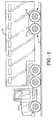
- FIG. 1is a diagrammatic side elevational view of a vehicle trailer on which the improved suspension assembly is mounted.
- FIG. 2is a rear elevational view of a pair of the improved suspension assemblies mounted on a trailer shown in dot dashed lines.
- FIG. 3is a perspective view of the improved vehicle suspension assembly of the present invention.
- FIG. 4is a side elevational view of the suspension assembly mounted on a vehicle with a ground engaging tire shown in dot dashed lines.
- FIG. 5is a top plan view of the improved vehicle suspension assembly.
- FIG. 6is a rear elevational view of the suspension assembly of FIG. 5 .
- FIG. 7is a side elevational view of the suspension assembly with the torsion axle shown in cross section.
- FIG. 8is an enlarged sectional view taken on line 8 - 8 , FIG. 5 .
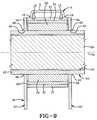
- FIG. 9is a greatly enlarged sectional view taken on line 9 - 9 , FIG. 7 .
- FIG. 10is a side elevational view of the vehicle suspension assembly at the start of a jounce movement.
- FIG. 11is a view similar to FIG. 10 with the vehicle suspension assembly moving toward a full jounce position.
- FIG. 12is a view similar to FIGS. 10 and 11 with the vehicle suspension assembly starting to move toward the rebound direction.
- FIG. 13is a view similar to FIGS. 10-12 with the vehicle suspension assembly in the full rebound position.
- a vehicle suspension system having the improved suspension assembly of the present inventionis indicated generally at 1 , and is shown particularly in FIGS. 3-9 mounted a vehicle 2 , such as a trailer of the type being towed by a tractor 3 .
- Vehicle 2is supported on a pair of frame rails 4 extending longitudinally along a length of the trailer.
- a pair of the improved suspension assemblies, each indicated generally at 5is mounted on a respective frame rail 4 generally adjacent a wheel 6 .
- Suspension assembly 5 as shown in FIG. 3includes a frame mounting bar 7 which is secured to one of the trailer frame rails 4 by a plurality of bolts which extend through holes 8 , by welding or other types of attachments.
- Frame bar 7preferably has a U-shaped channel configuration with web wall 9 and a pair of spaced legs 10 terminating in depending end flange portion 11 ( FIG. 8 ) formed by a pair of spaced flange legs 12 .
- Each flange leg 12is formed with a generally semicircular cutout 13 and has a plurality of reinforcing gussets 15 extending between each of the flange legs 12 .
- Torsion axle 25extends between a pair of the improved suspension assemblies as shown particularly in FIG. 2 , and includes a generally square-shaped outer tube 27 and an inner stub shaft 29 at each end thereof. Stub shaft 29 is movably rotatably mounted within outer tube 27 by a plurality of elastomeric strips or bars 31 ( FIG. 3 ) which are press-fitted within the hollow interior 33 of tube 27 , resiliently supporting stub shaft 29 therein.
- Torsion axle or first reaction member 25is similar to a well-known torsion axle, one type being sold under the trademark TOR FLEX® from Dexter Axle.
- Suspension assembly 5further includes an air spring support arm or second reaction member, indicated generally at 35 , which includes a pair of spaced support arm members 37 , each of which has a generally L-shaped configuration with a circular mounting leg 39 and an elongated leg 41 extending outwardly angularly therefrom.
- a pair of washers 38is located between arms 37 and collar 17 and bushing 21 to provide for a smooth sliding engagement therebetween.
- the outer distal ends of legs 41are connected by an air spring mounting plate 43 extending therebetween and preferably welded thereto.
- Each support arm 37is formed with a square-shaped opening 45 complementary to axle tube 27 for slidably receiving axle tube 27 therethrough where it is secured to legs 37 by welding or other attachment means at the pivot.
- An air spring 47is secured to mounting plate 43 by a plurality of bolts 48 ( FIG. 8 ) and at its upper end by bolts 49 to an irregularly shaped plate 50 which as best shown in FIGS. 3 and 8 .
- Plate 50is secured to the top end plate 51 of air spring 47 by bolts 49 , lugs or other attachment means and extends beneath and is welded to the bottom edges of legs 10 of U-shaped flange mounting bars 7 .
- Plate 50terminates in a curved end flange portion 53 ( FIG. 8 ) which terminates adjacent axle collar 17 .
- a spindle arm indicated generally at 55is attached at one end 57 to stub shaft 29 preferably by welding, after the stub shaft extends through a complementary-shaped square opening 59 formed in spindle arm end 57 ( FIG. 4 ).
- the opposite end of spindle arm 55is formed with a circular opening 61 ( FIG. 3 ) in which one end of a spindle 60 is secured preferably by welds.
- a brake assembly mounting plate 63is secured to spindle 60 for subsequent attachment to a brake assembly shown diagrammatically in FIG. 2 .
- Spindle 60supports a wheel/hub assembly in a manner well known in the art.
- an axis 70 which extends through the center of torsion axle 25 and stub shaft 29is coaxial with the axis about the pivot axis of air spring support arm 35 .
- both the pivot axis for the air spring mounting arm and the center axis of torsion axle 25are coaxial or are the same axis as opposed to the spaced axes for the air spring mounting arm and torsion axle of U.S. Pat. No. 6,340,165.
- Thisprovides for a considerably more compact, lighter weight air spring torsion bar assembly, which has a reduced number of components and a considerably shorter air spring mounting arm and frame mounting bar than the suspension assembly of the above-discussed U.S. Pat. No. 6,340,165.
- Air spring 47is shown as a double convolute air spring, but could be a triple convolute or rolling lobe air spring without affecting the concept of the invention. Furthermore, the air spring can use other internal fluids rather than air for its operation, although air is the preferred fluid which is supplied thereto from a compressor (not shown) usually mounted within the tractor or trailer and connected to a coupler 67 on the air spring by a air line (not shown). Coupler 67 is mounted on top end plate 51 of the air spring as shown in FIG. 6 . Furthermore, the coaxial arrangement of the air spring mounting arm and torsion axis provides for a shorter air spring mounting arm and enables the center line of the air spring to be generally in alignment or slightly beyond the axis of spindle 60 as shown in FIG. 5 . This again provides for a more compact, sturdy air suspension assembly than the prior art combination air spring and torsion axle suspension assembly.
- FIGS. 10-13The manner of operation of suspension assembly 5 is best shown in FIGS. 10-13 .
- FIG. 10shows the position of the air spring and mounting arm at the start of a jounce movement.
- FIG. 11shows both the torsion axle, and in particular stub shaft 29 and the air spring in a nearly full jounce position as shown by the counterclockwise pivotal movement of air spring support arm 35 in the direction of Arrow B and the rotational movement of stub shaft 29 in the direction of Arrow C.
- FIG. 12shows the start of the rebound of the suspension assembly with the initial rebound force being absorbed by elastomeric strips or bars 31 as shown by the clockwise rotation of stub shaft 29 (Arrow D).
- FIG. 10shows the position of the air spring and mounting arm at the start of a jounce movement.
- FIG. 11shows both the torsion axle, and in particular stub shaft 29 and the air spring in a nearly full jounce position as shown by the counterclockwise pivotal movement of air spring support arm 35 in the direction
- both stub shaft 29 and its associated elastomeric strips or bars 31 and air spring 47provide the desired stability to the suspension assembly by absorbing the various twisting and up and down or side to side movement exerted on the trailer wheels. Since the rubber torsion spring system of the present invention is in series with the air spring system with any load applied to the system and since each spring is in the path of the forces being applied and each spring deflects in inverse proportion to its spring rate, the softer of the springs deflects more than the stiffer of the springs. Thus, the total effective spring rate is therefore softer than the spring rate of either of the springs alone, and both springs deflect at the very same time
- torsion axle 25does not translate either vertically or horizontally, but rather only receives true rotational forces as a result of any input force from the tire wheel assemblies through spindle 60 and spindle arms 55 .
- torsion axle 25sees no translational movement in either of the vertical or horizontal plane, significantly lower stresses are felt by support arms 35 and torsion axle 25 thereby providing a smaller more lightweight, as well as more reliable suspension system.
- torsion axle 25will remain positioned relative to one another in the vertical plane as a result of their being affixed to the respective suspension frames with the respective flange mounting bars 7 .
- torsion axle 25which is positioned along the respective support arms 35 will provide movement between the free ends of torsion axle 25 because movement of support arms 25 will necessarily cause movement of the free end of the associated end of torsion axle 25 .
- the torsion axle and air springsboth react colinearly at a common pivot axis, it should be understood that each of these reaction members react to forces input through the spindle in series rather than parallel.
- a pneumatic or hydraulic shock absorbercould extend between air spring support arms 35 and mounting bar 7 or trailer frame 4 to assist in absorbing forces exerted on the vehicle wheels but is not essential for the operation of the present invention.
Landscapes
- Engineering & Computer Science (AREA)
- Mechanical Engineering (AREA)
- Vehicle Body Suspensions (AREA)
Abstract
Description
Claims (19)
Priority Applications (1)
| Application Number | Priority Date | Filing Date | Title |
|---|---|---|---|
| US12/117,283US7758056B2 (en) | 2008-05-08 | 2008-05-08 | Suspension assembly with coaxial torsion bar |
Applications Claiming Priority (1)
| Application Number | Priority Date | Filing Date | Title |
|---|---|---|---|
| US12/117,283US7758056B2 (en) | 2008-05-08 | 2008-05-08 | Suspension assembly with coaxial torsion bar |
Publications (2)
| Publication Number | Publication Date |
|---|---|
| US20090278328A1 US20090278328A1 (en) | 2009-11-12 |
| US7758056B2true US7758056B2 (en) | 2010-07-20 |
Family
ID=41266243
Family Applications (1)
| Application Number | Title | Priority Date | Filing Date |
|---|---|---|---|
| US12/117,283Expired - Fee RelatedUS7758056B2 (en) | 2008-05-08 | 2008-05-08 | Suspension assembly with coaxial torsion bar |
Country Status (1)
| Country | Link |
|---|---|
| US (1) | US7758056B2 (en) |
Cited By (12)
| Publication number | Priority date | Publication date | Assignee | Title |
|---|---|---|---|---|
| US20100225084A1 (en)* | 2008-12-30 | 2010-09-09 | Darco Trust | Vehicle suspension system |
| US20100270766A1 (en)* | 2009-04-22 | 2010-10-28 | Air Suspensions, Inc. | Suspension system with single moving element |
| US20110068550A1 (en)* | 2008-05-23 | 2011-03-24 | Systeme Nenuphar Inc. | Angular Adjusting System for Torsion Suspension and Torsion Suspension so Obtained |
| US20110095503A1 (en)* | 2009-10-22 | 2011-04-28 | Watson & Chalin Manufacturing, Inc. | Drop spindle independent suspension system |
| US20110101641A1 (en)* | 2009-09-17 | 2011-05-05 | Gm Global Technology Operations, Inc. | Structural component for rear frame structure of a motor vehicle |
| US20120217716A1 (en)* | 2011-02-24 | 2012-08-30 | GM Global Technology Operations LLC | Suspension of a vehicle axle and vehicle |
| US8720922B2 (en) | 2009-04-22 | 2014-05-13 | Transportation Technologies, Inc. | Suspension system with single moving element |
| US8727363B1 (en) | 2012-11-06 | 2014-05-20 | Transportation Technologies, Inc. | Suspension system having parallel air spring and rubber force reaction |
| US9039034B2 (en) | 2013-02-13 | 2015-05-26 | Transportation Technologies, Inc. | Multiple axle equalizing rubber suspension |
| US20180118298A1 (en)* | 2015-04-08 | 2018-05-03 | Ujet Vehicles S.À.R.L. | Motor-driven vehicle, in particular two-wheeled vehicle |
| US20240017778A1 (en)* | 2022-02-25 | 2024-01-18 | Jason Douglas COLLINS | Trailer axle |
| US11897307B1 (en)* | 2023-09-26 | 2024-02-13 | Flyer Next, LLC | Trailer suspension |
Families Citing this family (7)
| Publication number | Priority date | Publication date | Assignee | Title |
|---|---|---|---|---|
| GB0902695D0 (en)* | 2009-02-18 | 2009-04-01 | Rose Elizabeth D | Trailer suspension |
| CN102673332A (en)* | 2012-05-04 | 2012-09-19 | 河南速达电动汽车科技有限公司 | Independent suspension system for back torsion beam of electric automobile |
| US9138363B1 (en)* | 2014-04-04 | 2015-09-22 | Chung-Chuan LIN | Wheel independent suspension system for a mobility scooter |
| US10434833B1 (en)* | 2016-04-20 | 2019-10-08 | Alamo Group Inc. | Rotary cutter with torsional suspension system |
| CN108105302B (en)* | 2017-12-13 | 2019-12-31 | 中国飞机强度研究所 | Anti-instability air spring set |
| US20200361546A1 (en)* | 2019-05-14 | 2020-11-19 | Lippert Components, Inc. | Torsion axle pin box |
| CN113085799A (en)* | 2021-04-29 | 2021-07-09 | 谢成忠 | Be used for drawing trailer antiskid braced system |
Citations (26)
| Publication number | Priority date | Publication date | Assignee | Title |
|---|---|---|---|---|
| US2998981A (en) | 1957-03-11 | 1961-09-05 | Int Harvester Co | Vehicle running gear |
| US3078104A (en)* | 1961-06-07 | 1963-02-19 | Hawker Siddeley Canada Ltd | Independent rear suspension for semi-trailers |
| US3140880A (en)* | 1961-05-11 | 1964-07-14 | Neway Equipment Co | Suspension for automotive vehicles |
| US3784221A (en) | 1972-07-24 | 1974-01-08 | V Frasier | Air ride suspension for trucks |
| US4171830A (en) | 1978-03-02 | 1979-10-23 | Granning Suspensions, Inc. | Vehicle suspension lift system |
| US4966386A (en) | 1986-07-18 | 1990-10-30 | Alois Kober Kg | Torsion spring bar axle for vehicle trailers |
| US5161814A (en) | 1989-04-28 | 1992-11-10 | Walker Douglas W | Trailerable structure with retractable suspension |
| US5163701A (en) | 1991-09-09 | 1992-11-17 | Csn Manufacturing, Inc. | Torsion spring vehicle suspension |
| US5215328A (en) | 1991-03-01 | 1993-06-01 | Bono Mark J | Torsion suspension for a single axle |
| US5277450A (en)* | 1992-07-07 | 1994-01-11 | Henschen Curtiss W | Multiple stage torsion axle |
| US5366237A (en) | 1992-10-19 | 1994-11-22 | The Boler Company | Axle suspension systems |
| US5411268A (en)* | 1994-09-07 | 1995-05-02 | Normandie Casino | Game of skill and chance |
| US5427404A (en) | 1994-06-15 | 1995-06-27 | Paccar Inc. | Stiff beam suspension system |
| US5505482A (en) | 1994-08-24 | 1996-04-09 | Suspensions Incorporated | Road-railer suspension system having a spring lift and a stabilizer bar |
| US5505481A (en) | 1994-03-07 | 1996-04-09 | Suspensions Incorporated | Lift axle suspension system |
| US5540454A (en) | 1995-01-20 | 1996-07-30 | Suspensions Incorporated | Tag axle assembly |
| US5683098A (en) | 1996-04-19 | 1997-11-04 | Suspensions Incorporated | Suspension system and alignment mechanism therefor |
| US5690353A (en) | 1996-05-09 | 1997-11-25 | Suspensions Incorporated | Suspension system with improved beam |
| US5718445A (en) | 1994-08-24 | 1998-02-17 | Suspensions, Inc. | Vehicle suspension system |
| US5788263A (en) | 1996-05-09 | 1998-08-04 | Suspensions Incorporated | Suspension system with laminated beams |
| US5853183A (en) | 1996-12-02 | 1998-12-29 | Suspensions Incorporated | Lift mechanism for vehicle suspensions |
| US5924712A (en)* | 1996-05-30 | 1999-07-20 | Neway Anchorlok International, Inc. | Dual trailing arm vehicle suspension |
| US6340165B1 (en) | 1999-08-20 | 2002-01-22 | Gary L. Kelderman | Torsion axle and air bag vehicle suspension system |
| US20040188973A1 (en)* | 2003-01-15 | 2004-09-30 | Mark Molitor | Vehicle suspension assembly |
| US7077410B2 (en)* | 2002-09-11 | 2006-07-18 | Peerless Limited | Vehicle suspension system |
| US7516821B2 (en)* | 2004-08-27 | 2009-04-14 | Suspension Technology, Inc. | Brake system and suspension for use therewith |
- 2008
- 2008-05-08USUS12/117,283patent/US7758056B2/ennot_activeExpired - Fee Related
Patent Citations (27)
| Publication number | Priority date | Publication date | Assignee | Title |
|---|---|---|---|---|
| US2998981A (en) | 1957-03-11 | 1961-09-05 | Int Harvester Co | Vehicle running gear |
| US3140880A (en)* | 1961-05-11 | 1964-07-14 | Neway Equipment Co | Suspension for automotive vehicles |
| US3078104A (en)* | 1961-06-07 | 1963-02-19 | Hawker Siddeley Canada Ltd | Independent rear suspension for semi-trailers |
| US3784221A (en) | 1972-07-24 | 1974-01-08 | V Frasier | Air ride suspension for trucks |
| US4171830A (en) | 1978-03-02 | 1979-10-23 | Granning Suspensions, Inc. | Vehicle suspension lift system |
| US4966386A (en) | 1986-07-18 | 1990-10-30 | Alois Kober Kg | Torsion spring bar axle for vehicle trailers |
| US5161814A (en) | 1989-04-28 | 1992-11-10 | Walker Douglas W | Trailerable structure with retractable suspension |
| US5215328A (en) | 1991-03-01 | 1993-06-01 | Bono Mark J | Torsion suspension for a single axle |
| US5163701A (en) | 1991-09-09 | 1992-11-17 | Csn Manufacturing, Inc. | Torsion spring vehicle suspension |
| US5277450A (en)* | 1992-07-07 | 1994-01-11 | Henschen Curtiss W | Multiple stage torsion axle |
| US5366237A (en) | 1992-10-19 | 1994-11-22 | The Boler Company | Axle suspension systems |
| US5505481A (en) | 1994-03-07 | 1996-04-09 | Suspensions Incorporated | Lift axle suspension system |
| US5427404A (en) | 1994-06-15 | 1995-06-27 | Paccar Inc. | Stiff beam suspension system |
| US5505482A (en) | 1994-08-24 | 1996-04-09 | Suspensions Incorporated | Road-railer suspension system having a spring lift and a stabilizer bar |
| US5820156A (en) | 1994-08-24 | 1998-10-13 | Suspensions Incorporated | Vehicle suspension system |
| US5718445A (en) | 1994-08-24 | 1998-02-17 | Suspensions, Inc. | Vehicle suspension system |
| US5411268A (en)* | 1994-09-07 | 1995-05-02 | Normandie Casino | Game of skill and chance |
| US5540454A (en) | 1995-01-20 | 1996-07-30 | Suspensions Incorporated | Tag axle assembly |
| US5683098A (en) | 1996-04-19 | 1997-11-04 | Suspensions Incorporated | Suspension system and alignment mechanism therefor |
| US5788263A (en) | 1996-05-09 | 1998-08-04 | Suspensions Incorporated | Suspension system with laminated beams |
| US5690353A (en) | 1996-05-09 | 1997-11-25 | Suspensions Incorporated | Suspension system with improved beam |
| US5924712A (en)* | 1996-05-30 | 1999-07-20 | Neway Anchorlok International, Inc. | Dual trailing arm vehicle suspension |
| US5853183A (en) | 1996-12-02 | 1998-12-29 | Suspensions Incorporated | Lift mechanism for vehicle suspensions |
| US6340165B1 (en) | 1999-08-20 | 2002-01-22 | Gary L. Kelderman | Torsion axle and air bag vehicle suspension system |
| US7077410B2 (en)* | 2002-09-11 | 2006-07-18 | Peerless Limited | Vehicle suspension system |
| US20040188973A1 (en)* | 2003-01-15 | 2004-09-30 | Mark Molitor | Vehicle suspension assembly |
| US7516821B2 (en)* | 2004-08-27 | 2009-04-14 | Suspension Technology, Inc. | Brake system and suspension for use therewith |
Cited By (20)
| Publication number | Priority date | Publication date | Assignee | Title |
|---|---|---|---|---|
| US20110068550A1 (en)* | 2008-05-23 | 2011-03-24 | Systeme Nenuphar Inc. | Angular Adjusting System for Torsion Suspension and Torsion Suspension so Obtained |
| US8360448B2 (en)* | 2008-05-23 | 2013-01-29 | Système Nénuphar Inc. | Angular adjusting system for torsion suspension and torsion suspension so obtained |
| US20100225084A1 (en)* | 2008-12-30 | 2010-09-09 | Darco Trust | Vehicle suspension system |
| US8720922B2 (en) | 2009-04-22 | 2014-05-13 | Transportation Technologies, Inc. | Suspension system with single moving element |
| US20100270766A1 (en)* | 2009-04-22 | 2010-10-28 | Air Suspensions, Inc. | Suspension system with single moving element |
| US8328211B2 (en)* | 2009-04-22 | 2012-12-11 | Air Suspensions, Inc. | Suspension system with single moving element |
| US20110101641A1 (en)* | 2009-09-17 | 2011-05-05 | Gm Global Technology Operations, Inc. | Structural component for rear frame structure of a motor vehicle |
| US8348290B2 (en)* | 2009-09-17 | 2013-01-08 | GM Global Technology Operations LLC | Structural component for rear frame structure of a motor vehicle |
| US20110095503A1 (en)* | 2009-10-22 | 2011-04-28 | Watson & Chalin Manufacturing, Inc. | Drop spindle independent suspension system |
| US20120217716A1 (en)* | 2011-02-24 | 2012-08-30 | GM Global Technology Operations LLC | Suspension of a vehicle axle and vehicle |
| US8414001B2 (en)* | 2011-02-24 | 2013-04-09 | GM Global Technology Operations LLC | Suspension of a vehicle axle and vehicle |
| US8727363B1 (en) | 2012-11-06 | 2014-05-20 | Transportation Technologies, Inc. | Suspension system having parallel air spring and rubber force reaction |
| US9039034B2 (en) | 2013-02-13 | 2015-05-26 | Transportation Technologies, Inc. | Multiple axle equalizing rubber suspension |
| US9085209B2 (en) | 2013-02-13 | 2015-07-21 | Transportation Technologies, Inc. | Multiple axle equalizing rubber suspension (ERT) |
| US20180118298A1 (en)* | 2015-04-08 | 2018-05-03 | Ujet Vehicles S.À.R.L. | Motor-driven vehicle, in particular two-wheeled vehicle |
| US20240017778A1 (en)* | 2022-02-25 | 2024-01-18 | Jason Douglas COLLINS | Trailer axle |
| US12077232B2 (en)* | 2022-02-25 | 2024-09-03 | Norco Industries, Inc. | Trailer axle |
| US11897307B1 (en)* | 2023-09-26 | 2024-02-13 | Flyer Next, LLC | Trailer suspension |
| US20250100336A1 (en)* | 2023-09-26 | 2025-03-27 | Flyer Next, LLC | Trailer suspension |
| US12304271B2 (en)* | 2023-09-26 | 2025-05-20 | Flyer Next, LLC | Trailer suspension |
Also Published As
| Publication number | Publication date |
|---|---|
| US20090278328A1 (en) | 2009-11-12 |
Similar Documents
| Publication | Publication Date | Title |
|---|---|---|
| US7758056B2 (en) | Suspension assembly with coaxial torsion bar | |
| US7726674B2 (en) | Suspension assembly | |
| US8256782B2 (en) | Suspension assembly | |
| US6340165B1 (en) | Torsion axle and air bag vehicle suspension system | |
| US8226098B2 (en) | Suspension system with a retrofit suspension kit | |
| US8328211B2 (en) | Suspension system with single moving element | |
| US5470096A (en) | Wheeled vehicle suspension | |
| US8727363B1 (en) | Suspension system having parallel air spring and rubber force reaction | |
| KR101315872B1 (en) | Dual leaf vehicle suspension with j-shaped spring element | |
| US7520515B2 (en) | Steer axle suspension | |
| WO2014138559A2 (en) | Utility vehicle | |
| US20120200055A1 (en) | Axle tubes including protrusion and vehicle including same | |
| US5012885A (en) | Rear wheel suspension and steering system | |
| US9039034B2 (en) | Multiple axle equalizing rubber suspension | |
| JP2005529022A (en) | How to produce independent front wheel suspensions, cars equipped with such front wheel suspensions, and spring suspensions | |
| US8720922B2 (en) | Suspension system with single moving element | |
| US7178824B2 (en) | Walking beam trailer suspension slider | |
| US4061361A (en) | Vehicle suspensions | |
| US5380036A (en) | Vehicle rear suspension system | |
| CN201102453Y (en) | Automotive rear suspension system | |
| US2885217A (en) | Shock-absorbing vehicle suspension | |
| CN203920306U (en) | A kind of multi-link lever suspension fork | |
| US2464467A (en) | Spring suspension for automobile trailers | |
| CN2657960Y (en) | Double-arm, double-torsion-bar independent suspension device | |
| TWM655191U (en) | Transport vehicle frame |
Legal Events
| Date | Code | Title | Description |
|---|---|---|---|
| AS | Assignment | Owner name:AIR SUSPENSIONS, INC., OHIO Free format text:ASSIGNMENT OF ASSIGNORS INTEREST;ASSIGNORS:VANDENBERG, ERVIN K.;CROSTON, DAVID H.;REEL/FRAME:020920/0980 Effective date:20080403 | |
| STCF | Information on status: patent grant | Free format text:PATENTED CASE | |
| FEPP | Fee payment procedure | Free format text:PAYOR NUMBER ASSIGNED (ORIGINAL EVENT CODE: ASPN); ENTITY STATUS OF PATENT OWNER: SMALL ENTITY | |
| AS | Assignment | Owner name:TRANSPORTATION TECHNOLOGIES, INC., OHIO Free format text:ASSIGNMENT OF ASSIGNORS INTEREST;ASSIGNOR:AIR SUSPENSIONS, INC.;REEL/FRAME:031806/0351 Effective date:20131217 | |
| FPAY | Fee payment | Year of fee payment:4 | |
| MAFP | Maintenance fee payment | Free format text:PAYMENT OF MAINTENANCE FEE, 8TH YR, SMALL ENTITY (ORIGINAL EVENT CODE: M2552) Year of fee payment:8 | |
| FEPP | Fee payment procedure | Free format text:MAINTENANCE FEE REMINDER MAILED (ORIGINAL EVENT CODE: REM.); ENTITY STATUS OF PATENT OWNER: SMALL ENTITY | |
| LAPS | Lapse for failure to pay maintenance fees | Free format text:PATENT EXPIRED FOR FAILURE TO PAY MAINTENANCE FEES (ORIGINAL EVENT CODE: EXP.); ENTITY STATUS OF PATENT OWNER: SMALL ENTITY | |
| STCH | Information on status: patent discontinuation | Free format text:PATENT EXPIRED DUE TO NONPAYMENT OF MAINTENANCE FEES UNDER 37 CFR 1.362 | |
| FP | Lapsed due to failure to pay maintenance fee | Effective date:20220720 |