US7757450B2 - Control joint - Google Patents
Control jointDownload PDFInfo
- Publication number
- US7757450B2 US7757450B2US11/034,591US3459105AUS7757450B2US 7757450 B2US7757450 B2US 7757450B2US 3459105 AUS3459105 AUS 3459105AUS 7757450 B2US7757450 B2US 7757450B2
- Authority
- US
- United States
- Prior art keywords
- wall
- screed
- base portion
- plaster
- control joint
- Prior art date
- Legal status (The legal status is an assumption and is not a legal conclusion. Google has not performed a legal analysis and makes no representation as to the accuracy of the status listed.)
- Active, expires
Links
- 239000011505plasterSubstances0.000claimsabstractdescription82
- 239000000463materialSubstances0.000claimsabstractdescription50
- 230000001154acute effectEffects0.000claimsdescription4
- 125000000391vinyl groupChemical group[H]C([*])=C([H])[H]0.000claimsdescription4
- 229920002554vinyl polymerPolymers0.000claimsdescription4
- 238000010276constructionMethods0.000abstractdescription9
- 230000000694effectsEffects0.000abstractdescription3
- 230000008878couplingEffects0.000description17
- 238000010168coupling processMethods0.000description17
- 238000005859coupling reactionMethods0.000description17
- 238000000034methodMethods0.000description12
- 239000004567concreteSubstances0.000description10
- 230000014759maintenance of locationEffects0.000description7
- 230000008602contractionEffects0.000description4
- 238000009434installationMethods0.000description4
- 239000000853adhesiveSubstances0.000description3
- 230000001070adhesive effectEffects0.000description3
- 239000002023woodSubstances0.000description3
- 239000011449brickSubstances0.000description2
- 239000004568cementSubstances0.000description2
- 238000001125extrusionMethods0.000description2
- 230000009969flowable effectEffects0.000description2
- 239000002184metalSubstances0.000description2
- 239000007769metal materialSubstances0.000description2
- 239000002861polymer materialSubstances0.000description2
- 239000004800polyvinyl chlorideSubstances0.000description2
- 230000000717retained effectEffects0.000description2
- 239000000565sealantSubstances0.000description2
- 229910000831SteelInorganic materials0.000description1
- 238000013459approachMethods0.000description1
- 239000011324beadSubstances0.000description1
- 230000015572biosynthetic processEffects0.000description1
- 238000009435building constructionMethods0.000description1
- 239000004566building materialSubstances0.000description1
- 238000001035dryingMethods0.000description1
- 238000009432framingMethods0.000description1
- 239000000203mixtureSubstances0.000description1
- 229920001296polysiloxanePolymers0.000description1
- 229920000915polyvinyl chloridePolymers0.000description1
- 239000007787solidSubstances0.000description1
- 239000010959steelSubstances0.000description1
Images


Classifications
- E—FIXED CONSTRUCTIONS
- E04—BUILDING
- E04F—FINISHING WORK ON BUILDINGS, e.g. STAIRS, FLOORS
- E04F13/00—Coverings or linings, e.g. for walls or ceilings
- E04F13/02—Coverings or linings, e.g. for walls or ceilings of plastic materials hardening after applying, e.g. plaster
- E04F13/04—Bases for plaster
- E04F13/06—Edge-protecting borders
- E04F2013/066—Edge-protecting borders for expansion joints between two plaster layers
Definitions
- the inventionrelates to building construction components and, more particularly, to a flexible control joint for walls of dissimilar construction which facilitates the application of different thicknesses of plaster or similar material to the walls.
- Plaster, cement and stucco-type building materialshave been employed in the construction of walls for residential and commercial buildings for many years to achieve a variety of different designs and wall textures.
- Various methods and application techniques exist for applying such materials to walls and other structuresOne such method that is commonly employed involves attaching lath material to a wall frame constructed from wood or metal studs. The lath material serves to stabilize the plaster while it is in its flowable state prior to drying. Similar approaches are also commonly employed when the underlying structure is fabricated from, for example, concrete or concrete blocks. The lath material is applied to the wall surface (exterior or interior—what ever the case may be) and then the plaster material is applied to the lath. In other applications, however, the plaster is applied directly to sheathing or wallboard material.
- the walls of one structuremay move relative to the walls of the adjacent structure at different rates due to differences in the thermal expansion and contraction characteristics of the underlying materials.
- Plaster materialis often applied to such wall structures and control joint members are applied along the edges of the wall structures to form screed walls for the plaster which protect the otherwise exposed ends of the plaster.
- Flexible control jointshave been developed to span between the dissimilar wall structures and serve to form screed walls of identical heights which accommodate amounts of plaster materials that have the same thicknesses on each wall structure.
- a flexible control jointthat has a first base portion and a first screed wall that has a first proximal end that protrudes from the first base portion and a first distal end that is remote from the first base portion.
- the control joint of this embodimentfurther has a second base portion and a second screed wall that has a second proximal end that protrudes from the second base portion and a second distal end that is remote from the second base portion.
- a flexible attachment assemblyis attached between the first screed wall and the second screed wall such that the first and second screed walls are in spaced relationship to each other. The flexible attachment assembly facilitates flexible movement between the first and second screed walls.
- Another embodiment of the present inventioncomprises a flexible control joint that includes a first base portion and a first screed wall that has a first proximal end that protrudes from the first base portion and a first distal end that is remote from the first base portion.
- the control jointfurther has a second base portion and a second screed wall that has a second proximal end that protrudes from the second base portion and a second distal end that is remote from the second base portion.
- a first intermediate webis attached to the first distal end of the first screed wall.
- the first intermediate webhas a first intermediate web end intermediate the first proximal end of the first screed wall and the second proximal end of the second screed wall.
- the first intermediate web endis spaced from the first proximal end and the second proximal end.
- a second intermediate webis attached to the first intermediate web end and the second distal end of the second screed wall and extends therebetween to facilitate flexible movement between the first and second screed walls.
- a first plaster-retainerprotrudes from the first screed wall and a second plaster-retainer protrudes from the second screed wall.
- Another embodiment of the present inventioncomprises a method for constructing walls for a multistory building.
- One version of the methodincludes constructing a first wall that has a first exterior surface and constructing a second wall above the first wall such that a joint is formed therebetween and such that the second wall has a second exterior surface.
- the methodfurther includes attaching a flexible control joint to the first exterior surface and the second exterior surface such that the flexible control joint spans the joint therebetween and permits movement between the first wall and the second wall.
- the flexible control jointdefines a first plaster level remote from the first exterior surface and a second plaster level remote from the second exterior surface.
- the methodalso includes applying first plaster material to the first exterior surface such that the first plaster material has a first thickness that corresponds to the first plaster level and applying second plaster material to the second exterior surface such that the second plaster material has a second thickness that corresponds to the second plaster level.
- Another embodiment of the present inventioncomprises a building method that includes constructing a first wall portion that has a first exterior surface and constructing a second wall portion adjacent to the first wall portion such that a wall joint is formed therebetween and wherein the second wall portion has a second exterior surface.
- the methodalso includes attaching a flexible control joint to the first exterior surface and the second exterior surface such that the flexible control joint spans the wall joint therebetween and permits movement between the first wall portion and the second wall portion.
- the flexible control jointdefines a first plaster level remote from the first exterior surface and a second plaster level remote from the second exterior surface.
- a first plaster materialis applied to the first exterior surface such that the first plaster material has a first thickness that corresponds to the first plaster level and a second plaster material is applied to the second exterior surface such that the second plaster material has a second thickness that corresponds to the second plaster level.
- the corner assemblycomprises a first control joint that has a first base portion and a first screed wall that has a first proximal end that protrudes from the first base portion and a first distal end that is remote from the first base portion.
- the first control jointfurther has a second base portion and a second screed wall that has a second proximal end that protrudes from the second base portion and a second distal end that is remote from the second base portion.
- a flexible attachment assemblyis attached between the first screed wall and the second screed wall such that the first and second screed walls are in spaced relationship to each other.
- the flexible attachment assemblyfacilitates flexible movement between the first and second screed walls.
- the corner assemblyfurther includes a second control joint that has another first base portion and another first screed wall that has another first proximal end that protrudes from the another first base portion and another first distal end that is remote from the another first base portion.
- the second control jointfurther includes another second base portion that has another second screed wall that has another second proximal end that protrudes from the another second base portion and another second distal end that is remote from the another second base portion.
- Another flexible attachment assemblyis attached between the another first screed wall and the another second screed wall such that the another first screed wall and the another second screed wall are in spaced relationship to each other.
- the another flexible attachment assemblyfacilitates flexible movement between the another first screed wall and the another second screed wall and wherein an end of the first base portion abuts an end of the another first base portion and wherein an end of the second base portion abuts an end of the another second base portion.
- Another embodiment of the subject inventioncomprises a T-arrangement for forming screed walls for adjacent amounts of plaster that includes at least three control joints.
- Each control jointhas a first base portion and a first screed wall that has a first proximal end that protrudes from the first base portion.
- the first screed wallhas a first distal end that is located a first distance away from the first base portion.
- Each control jointfurther has a second base portion and a second screed wall that has a second proximal end that protrudes from the second base portion.
- the second screed wallhas a second distal end that is located a second distance away from the second base portion. The second distance is different from the first distance.
- a flexible attachment assemblyis attached between the first screed wall and the second screed wall such that the first and second screed walls are in spaced relationship to each other.
- the flexible attachment assemblyfacilitates flexible movement between the first and second screed walls.
- the T-arrangementfurther includes an attachment medium that attaches the control joints together to form the T-arrangement.
- FIG. 1is a plan view of two portions of adjacent wall structures having an embodiment of the control joint of the present invention therebetween;
- FIG. 2is a partial cross-sectional view of the adjacent walls and control joint depicted in FIG. 1 taken along line II-II in FIG. 1 ;
- FIG. 3is an end view of one embodiment of a control joint of the present invention.
- FIG. 4is a partial top view of the control joint of FIG. 2 ;
- FIG. 5is a plan view of another wall arrangement including two portions of adjacent wall structures and an embodiment of the control joint of the present invention therebetween;
- FIG. 6is a partial plan view of two control joint embodiments of the present invention abutted together to form a corner assembly embodiment of the present invention
- FIG. 7is another partial plan view of the corner assembly of FIG. 6 with two amounts of plaster material applied thereto;
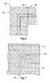
- FIG. 8is a plan view of a portion of a “T”-arrangement of the present invention formed from embodiments of the control joint of the present invention and having different thicknesses of plaster applied thereto;
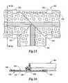
- FIG. 9is a cross-sectional view of the “T” arrangement of FIG. 8 taken along line IX-IX in FIG. 8 ;
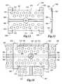
- FIG. 10is a partial top view of the “T”-arrangement depicted in FIGS. 8 and 9 prior to the application of the plaster material;
- FIG. 11is a bottom view of the “T”-arrangement of FIG. 10 ;
- FIG. 12is a top view of a coupling piece embodiment of the present invention.
- FIG. 13is a side elevational view of the coupling piece embodiment depicted in FIG. 12 ;
- FIG. 14is a bottom view of a coupling piece embodiment of the present invention attached to the “T”-arrangement depicted in FIGS. 10 and 11 ;
- FIG. 15is a top view of the coupling piece and “T”-arrangement of FIG. 14 ;
- FIG. 16is a partial cross-sectional view of the coupling piece and “T”-arrangement depicted in FIG. 15 taken along line XV-XV in FIG. 15 .
- FIG. 1illustrates one embodiment of the control joint 100 of the present invention used in connection with a multistory building 10 .
- various embodiments of the control joint of the present inventionmay be effectively used in connection with multistory structures that have walls constructed from dissimilar materials which would likely have differing expansion and contraction characteristics.
- the first story 12is fabricated from concrete block or solid concrete 14 to establish a first wall 16 that has a first exterior wall surface 18 .
- the second or upper story 20 located on and attached to the first wall 16may, for example, be constructed from wood or metal framing components 22 .
- Wall board material 24such as that material sold under the trademark CELOTEX or other sheet materials may be attached thereto to form a second wall 26 that has a second exterior wall surface 28 .
- the second exterior wall surface 28may be substantially coplanar with the first exterior wall surface 18 .
- a space or joint 30is formed between the first story wall 16 and the second story wall 26 .
- the control joint 100 of the present inventionis sized to span the joint 30 as shown in FIG. 1 .
- one embodiment of the control joint 100includes a first base portion 110 and a second base portion 120 .
- a first screed wall 130protrudes from the first base portion 110 and a second screed wall 140 protrudes from the second base portion 120 .
- a flexible attachment assembly generally designated as 150extends between the first screed wall 130 and the second screed wall 140 to facilitate movement between the first screed wall 130 and the second screed wall 140 .
- the first screed wall 130has a first proximal end 132 that is attached to or protrudes from the first base portion 110 .
- the first screed wall 130further has a first distal end 134 that is located remote from the first base portion 110 .
- the first distal end 134may be located a distance “A” from the first base portion 110 wherein distance “A” corresponds to a desired thickness of second plaster material 210 to be applied to the second exterior surface 28 of the second story wall 26 as will be discussed in further detail below.
- distance “A”may be approximately 7 ⁇ 8 of an inch.
- the second screed wall 140has a second proximal end 142 that is attached to or protrudes from the second base portion 120 .
- the second screed wall 140further has a second distal end 144 located a distance “B” from the second base portion 120 wherein distance “B” corresponds to a desired thickness of first plaster material 200 to be applied to the first exterior wall surface 18 of the first wall 16 as will be discussed in further detail below.
- distance “B”may be approximately 1 ⁇ 2 of an inch.
- the control joint 100could be fabricated such that distance “B” is greater than distance “A”.
- the flexible attachment assembly 150may have an accordion-like shape and include a first intermediate web 160 and a second intermediate web 170 .
- the first intermediate web 160is attached to or protrudes from the first distal end 134 of the first screed wall 130 and extends toward the first proximal end 132 of the first screed wall 130 to terminate in a first intermediate web end 162 .
- the first intermediate web end 162is spaced from the first proximal end 132 of the first screed wall 130 a distance “C” and from the second proximal end 142 of the second screed wall 140 a distance “D”.
- distance Ccould be approximately 1 ⁇ 4 inch and distance “D” could be approximately 1 ⁇ 4 inch. Other distances could also be employed which are sufficient to enable the first and second screed walls 130 , 140 to move relative to each other.
- the control joint 100 of the present inventionis fabricated from vinyl material utilizing conventional extrusion techniques and equipment.
- Exterior Grade polyvinylchloride (PVC)having the following grade numbers is particularly well-suited for exterior applications: ASTM-D-4216, ASTM-C-1063, and ASTM-D-1784.
- PVCExterior Grade polyvinylchloride
- ASTM-D-4216ASTM-D-4216
- ASTM-C-1063ASTM-D-1784
- other control joint embodimentscould be fabricated from other polymer materials having the desired ultraviolet light resistance, etc. or metal materials or the like could be employed without departing from the spirit and scope of the present invention.
- At least one and preferably a series of holes 112are provided through the first base portion 110 .
- Holes 112may be round as shown and may be provided in various sizes. See FIG. 3 . In the alternative, holes 112 may be provided in other shapes, sizes and arrangements without departing from the spirit and scope of the present invention.
- a series of fastener holes 114are provided through the first base portion 110 to receive fasteners therethrough for fastening the first base portion 110 to the first wall 16 as will be discussed in further detail below.
- holes 122are provided through the second base portion 120 .
- Holes 122may be round as shown and may be provided in various sizes. In the alternative, holes 122 may be provided in other shapes, sizes and arrangements without departing from the spirit and scope of the present invention.
- a series of fastener holes 124are provided through the second base portion 120 to receive fasteners therethrough for fastening the second base portion 120 to the second wall 26 as will be discussed in further detail below.
- the first screed wall 130may be formed with a first plaster retainer 136 .
- the first plaster retainer 136is formed at an acute angle with the first screed wall 130 .
- the first plaster retainer 136could be formed at various angles with respect to the first screed portion without departing from the spirit and scope of the present invention.
- the second screed wallis formed with a second plaster retainer 146 .
- the second plaster retainer 146is formed at an acute angle with the second screed wall 140 .
- the second plaster retainer 146could be formed at various angles with respect to the second screed portion without departing from the spirit and scope of the present invention.
- the control joint 100may be used as follows. After the first wall 16 and the second wall 26 have been constructed such that a space or joint 30 is formed therebetween, the control joint 100 is oriented such that it spans the joint 30 and the first base portion 110 is in confronting relationship with the outer surface 18 of the first wall 16 . Suitable fasteners 119 are inserted through at least some of the fastener holes 114 in the first base portion 110 to attach the first base portion to the first wall 16 .
- Fasteners 119may comprise conventional fasteners that are suited for the types of materials from which the first wall is fabricated.
- fasteners 119may comprise concrete fasteners, screws, nails, etc. In FIG. 1 , for example, fasteners 119 comprise conventional concrete fasteners.
- the second base portion 120is also oriented in confronting relationship with the outer surface 28 of the second wall 26 .
- Suitable fasteners 121are inserted through at least some of the fastener holes 124 in the second base portion 120 to attaché the second base portion 120 to the second wall 26 .
- Fasteners 121may comprise conventional fasteners that are suited for the types of materials from which the first wall is fabricated.
- fasteners 121may comprise concrete fasteners, screws, nails, etc.
- fasteners 119comprise conventional nails.
- the first amount of plaster 200is applied to the exterior surface 18 of the first wall 16 so that the outer surface 201 of the first plaster 200 stops at or is substantially even with the second distal end 144 of the second screed wall 140 as shown in FIG. 1 .
- the installermay find it convenient to place a portion of a screed tool or other type of leveling tool on the second distal end 144 to screed off the excess plaster so that the first amount of plaster has a substantially uniform thickness.
- the thickness of the first amount of plaster 200is substantially equivalent to distance “B” in this embodiment.
- the plaster 200covers the second base portion 210 and the heads of fasteners 120 .
- the second plaster retainer 146serves to assist in the retention of the first plaster 200 in abutting relationship with respect to the second screed wall 140 as shown in FIG. 1 .
- a second amount of plaster 210is applied to the outer surface 28 of the second wall 26 so that the outer surface 211 of the second amount of plaster 210 stops at or is substantially even with the first distal end 134 of the first screed wall 130 as shown in FIG. 1 .
- the installermay find it convenient to place a portion of the screed tool or other leveling tool on the first distal end to screed off or remove the excess plaster so that the second amount of plaster has a substantially uniform thickness.
- the thickness of the second amount of plaster 210is substantially equivalent to distance “A” in this embodiment.
- the second plaster 210covers the first base portion 110 and the heads of fasteners 121 .
- the first plaster retainer 136serves to assist in the retention of the second plaster 210 in abutting relationship with the first screed wall 130 as shown in FIG. 1 .
- the term “plaster”encompasses not only commercially available wall plaster materials, cement and stucco materials, but also essentially any materials that are flowable in an uncured state and which solidify in a cured state.
- first story and second story and “first wall” and “second wall”have been used herein in an exemplary manner to described one use of various embodiments of the subject invention. Such terms should in no way be deemed as limiting use of various embodiments to use solely between first and second story walls.
- Various embodiments of the present inventioncould be effectively used between a varieties of adjoining walls regardless of which stories the adjacent walls are located on.
- various embodiments of the present inventionhave been described herein as being used between adjoining walls wherein the joint formed between the walls essentially extends horizontally between the walls.
- the spatial orientation (i.e., horizontal, vertical, or angled orientation) of the joint formed between adjacent wallsis not important to the effective operation of various embodiments of the present invention.
- various embodiments of the control joint 100 present inventioncould, for example, be effectively employed at the vertically extending joint 30 ′ formed between two vertically extending walls 26 ′, 16 ′ which may be of similar or dissimilar construction in the manners described above.
- control joint of the present inventioncould be used in connection with surfaces that are oriented on an angle to form a flexible joint therebetween and to provide screed walls for adjacent amounts of plaster applied to the surfaces without departing from the spirit and scope of the present invention.
- Various embodiments of the present inventionmay also be used to form screed edges for plaster arrangements that are employed to create desired aesthetic effects such as the method of use illustrated in FIGS. 6 and 7 .
- pieces 302 , 304 of control joint 100may be mitered to form a corner arrangement 300 .
- the pieces 302 , 304 of control joint 100may be held together for installation purposes by, for example, commercially available tape 306 or other appropriate types of adhesive mediums.
- the pieces 302 , 304may be attached to underlying structures (i.e., wallboard, concrete, brick, etc.) by appropriate fasteners in the manner described above.
- the plaster materials 310 , 320may be applied thereto as shown in FIG. 7 .
- the thicknesses of the applied plaster materials 310 , 320may be governed by the heights of the first and second screed walls (distances “A” and “B” as described above). As in the other embodiments, the distances “A” and “B” are unequal.
- FIGS. 8-16Yet another embodiment of the present invention is depicted in FIGS. 8-16 . More particularly and with reference to FIGS. 8 and 9 , pieces 402 , 404 and 406 of control joint 100 may be mitered to form a “T” arrangement 400 that forms screed walls for supporting a first amount of plaster 410 that has a first thickness and a second amount of plaster 412 that has a second thickness and a third amount of plaster 414 that has a third thickness that is equal to the second thickness as will be discussed in further detail below.
- the pieces 402 , 404 , 406 of “T” arrangement 400may be held together for installation purposes by an attachment medium 419 .
- the attachment medium 419comprises pieces of commercially available tape 420 as shown in FIG. 11 .
- the attachment medium 419may comprise a commercially available adhesive medium or sealant such as silicone caulking 422 or the like that is applied to the joints wherein the pieces 402 , 404 , 406 come together as shown in FIG. 10 .
- a coupling piece 500may be employed to further support the pieces 402 , 404 , 406 in the interconnected orientation shown in FIGS. 8-11 .
- the coupling piece 500may be configured as shown in FIGS. 12 and 13 .
- the coupling piece 500includes a base portion 502 that is preferably sized to span the joints formed by the pieces 402 , 404 , 406 of the “T” arrangement 400 . See FIG. 14 .
- a hole 504is centrally located in the base portion 502 to assist the installer in centrally positioning the coupling piece 500 during installation. Protruding laterally outward from diametrically opposite portions of hole 504 are pairs of spaced legs 506 , 508 .
- a collection of holes 510are provided through the base portion 502 as shown in FIG. 12 to facilitate retention of the plaster materials, if desired. Holes 510 may be round as shown and may be provided in various sizes. In the alternative, holes 510 may be provided in other shapes, sizes and arrangements without departing from the spirit and scope of the present invention.
- a series of fastener holes 512are provided through the first base portion 502 to enable fasteners 514 for fastening the base portion 502 to an underlying structure 600 as will be discussed in further detail below.
- the coupling piece 500further has four clip arms 520 formed on the base portion to enable the coupling piece 500 to be clipped onto the “T” arrangement in the manner shown in FIGS. 9 and 14 - 16 .
- the legs 506 on each side of the central hole 504 in the base portion 502are received in the space or inverted V-shaped trough 171 formed between the second screed wall 140 and the second intermediate web 170 and the legs 508 on each side of the central hole 504 are received in the space or inverted V-shaped trough 161 between the first screed wall 130 and the first intermediate web 160 .
- Such arrangementprovides significant support to the “T” arrangement where the pieces 402 , 404 , 406 come together.
- the coupling pieceis fabricated from vinyl or the types of Polyvinylchloride described above utilizing conventional extrusion equipment and techniques.
- the coupling piece 500may be fabricated from a variety of other suitable polymer materials, metal material, etc. without departing from the spirit and scope of the present invention.
- each of the pieces 402 , 404 , 406is mitered in a desired manner to enable those ends to be abutted together as illustrated in FIGS. 10 and 11 .
- the readerwill appreciate that the other ends of the pieces 402 , 404 , 406 may be similarly mitered to enable those ends to be adjoined in a similar manner to other pieces of control joint 100 .
- the ends of pieces 402 , 404 , 406may be cut utilizing conventional cutting equipment commonly employed to cut banding beads and the like.
- the ends of the pieces 402 , 404 , 406are cut at desired angles, they are abutted together and they may be retained in that position by applying segments of commercially available tape 420 . See FIG. 11 .
- adhesive medium, sealant or caulking 422may be applied as shown in FIG. 10 .
- one or more of the coupling pieces 500are attached to the underlying structure 600 by fasteners 602 that extend through the fastener holes 512 in the base portion 502 .
- the underlying structure 600may be fabricated from a variety of different materials, such as wood, steel, brick, concrete, wallboard, etc. Appropriate fasteners 602 such as nails, screws, concrete fasteners, etc. may be used depending upon the composition of the underlying structure 600 .
- the “T”-arrangement 400may be snapped into the coupling pieces 500 and temporarily retained in position.
- Such arrangementmay also enable the installer to slide the “T”-arrangement 400 in the coupling pieces 500 to locate the “T”-arrangement 400 in the desired position.
- the pieces 402 , 404 , 406(and other pieces of control joint 100 attached thereto) may be attached to the underlying structure 600 by conventional fasteners 602 in the manner described above.
- the plaster materials 410 , 412 , 414may be applied thereto as shown in FIG. 8 .
- the thicknesses of the applied plaster materials 410 , 412 , 414may be governed by the heights of the first and second screed walls (distances “A” and “B” as described above). As in the other embodiments, the distances “A” and “B” are unequal.
- the unique and novel control joint embodiments of the present inventionsolve many problems encountered when applying different thicknesses of plaster along a building wall or walls.
- Such inventionprovides an effective way of establishing the desired thickness of materials to be applied while forming screed walls along a point wherein the different thicknesses of material are adjacent to each other.
- Various embodiments of the subject inventionalso enable the first screed wall to move independent from the second screed wall to accommodate different material movements due to, for example, differences in thermal expansion and contraction.
- various embodiments of the control joint of the present inventionare particularly well suited for use in connection with adjoining walls of dissimilar construction, various embodiments of the present invention can also be effectively used along joints between walls of like construction.
- the scope of protection afforded to various embodiments of the present inventionshould not solely be limited to applications involving use with walls, structures, etc. that are of dissimilar construction.
Landscapes
- Engineering & Computer Science (AREA)
- Architecture (AREA)
- Civil Engineering (AREA)
- Structural Engineering (AREA)
- Finishing Walls (AREA)
Abstract
Description
Claims (8)
Priority Applications (2)
| Application Number | Priority Date | Filing Date | Title |
|---|---|---|---|
| US11/034,591US7757450B2 (en) | 2005-01-13 | 2005-01-13 | Control joint |
| CA002532765ACA2532765A1 (en) | 2005-01-13 | 2006-01-11 | Control joint |
Applications Claiming Priority (1)
| Application Number | Priority Date | Filing Date | Title |
|---|---|---|---|
| US11/034,591US7757450B2 (en) | 2005-01-13 | 2005-01-13 | Control joint |
Publications (2)
| Publication Number | Publication Date |
|---|---|
| US20060150553A1 US20060150553A1 (en) | 2006-07-13 |
| US7757450B2true US7757450B2 (en) | 2010-07-20 |
Family
ID=36651804
Family Applications (1)
| Application Number | Title | Priority Date | Filing Date |
|---|---|---|---|
| US11/034,591Active2027-03-07US7757450B2 (en) | 2005-01-13 | 2005-01-13 | Control joint |
Country Status (2)
| Country | Link |
|---|---|
| US (1) | US7757450B2 (en) |
| CA (1) | CA2532765A1 (en) |
Cited By (33)
| Publication number | Priority date | Publication date | Assignee | Title |
|---|---|---|---|---|
| US20110197530A1 (en)* | 2010-01-13 | 2011-08-18 | Pacific Insulated Panel Llc | Composite insulating building panel and system and method for attaching building panels |
| US20110296768A1 (en)* | 2010-06-07 | 2011-12-08 | Clearfield Howard M | Method for sealing flashing joints below flashing |
| US8826481B1 (en)* | 2011-10-27 | 2014-09-09 | Versaflex, Inc. | Waterproof expansion joint |
| US9068297B2 (en) | 2012-11-16 | 2015-06-30 | Emseal Joint Systems Ltd. | Expansion joint system |
| US9322163B1 (en)* | 2011-10-14 | 2016-04-26 | Emseal Joint Systems, Ltd. | Flexible expansion joint seal |
| US9528262B2 (en) | 2008-11-20 | 2016-12-27 | Emseal Joint Systems Ltd. | Fire and water resistant expansion joint system |
| US9631362B2 (en) | 2008-11-20 | 2017-04-25 | Emseal Joint Systems Ltd. | Precompressed water and/or fire resistant tunnel expansion joint systems, and transitions |
| US9637915B1 (en) | 2008-11-20 | 2017-05-02 | Emseal Joint Systems Ltd. | Factory fabricated precompressed water and/or fire resistant expansion joint system transition |
| US9670666B1 (en) | 2008-11-20 | 2017-06-06 | Emseal Joint Sytstems Ltd. | Fire and water resistant expansion joint system |
| US9689158B1 (en) | 2009-03-24 | 2017-06-27 | Emseal Joint Systems Ltd. | Fire and water resistant expansion and seismic joint system |
| US9689157B1 (en) | 2009-03-24 | 2017-06-27 | Emseal Joint Systems Ltd. | Fire and water resistant expansion and seismic joint system |
| USD792610S1 (en) | 2015-08-28 | 2017-07-18 | Clarkwestern Dietrich Building Systems Llc | Control joint with metal lath attachment feature |
| US9739050B1 (en) | 2011-10-14 | 2017-08-22 | Emseal Joint Systems Ltd. | Flexible expansion joint seal system |
| USD800344S1 (en) | 2016-02-05 | 2017-10-17 | Clarkwestern Dietrich Building Systems Llc | Casing bead with a ribbed flange |
| USD800346S1 (en) | 2016-02-05 | 2017-10-17 | Clarkwestern Dietrich Building Systems Llc | Control joint with ribbed flanges |
| USD800921S1 (en) | 2016-02-05 | 2017-10-24 | Clarkwestern Dietrich Building Systems Llc | Framing accessory with a ribbed flange |
| US10017936B1 (en) | 2010-11-24 | 2018-07-10 | Innovations & Ideas, Llc | Casing bead control joint |
| US20180281346A1 (en)* | 2017-03-30 | 2018-10-04 | Joe Green Pte. Ltd. | Reinforcement tape and an assembly of the reinforcement tape and a substrate |
| USD839454S1 (en)* | 2017-04-24 | 2019-01-29 | Robert ZIEGAN | Grid edging |
| USD841833S1 (en) | 2017-01-09 | 2019-02-26 | Clarkwestern Dietrich Building Systems Llc | Channel reveal with ribbed and perforated flanges |
| USD842496S1 (en) | 2017-01-09 | 2019-03-05 | Clarkwestern Dietrich Building Systems Llc | Casing bead with a ribbed and perforated flange |
| USD842497S1 (en)* | 2017-01-09 | 2019-03-05 | Clarkwestern Dietrich Building Systems Llc | Control joint with ribbed and perforated flanges |
| USD843015S1 (en) | 2017-01-09 | 2019-03-12 | Clarkwestern Dietrich Building Systems Llc | Framing accessory with a ribbed and perforated flange |
| US10316661B2 (en) | 2008-11-20 | 2019-06-11 | Emseal Joint Systems, Ltd. | Water and/or fire resistant tunnel expansion joint systems |
| US10407840B2 (en) | 2017-05-16 | 2019-09-10 | Robert ZIEGAN | Surface system and method of installation |
| US10801537B2 (en) | 2018-01-05 | 2020-10-13 | Nova USA Wood Products, LLC | Resilient mounting clips, panel mount systems including the same, and associated methods |
| US10851542B2 (en) | 2008-11-20 | 2020-12-01 | Emseal Joint Systems Ltd. | Fire and water resistant, integrated wall and roof expansion joint seal system |
| USD904649S1 (en) | 2019-09-25 | 2020-12-08 | Clarkwestern Dietrich Building Systems Llc | Weep screed |
| RU206681U1 (en)* | 2020-03-17 | 2021-09-22 | Алексей Владимирович Беспалов | PLASTER LIGHTHOUSE |
| US11180995B2 (en) | 2008-11-20 | 2021-11-23 | Emseal Joint Systems, Ltd. | Water and/or fire resistant tunnel expansion joint systems |
| US11486150B2 (en) | 2016-12-20 | 2022-11-01 | Clarkwestern Dietrich Building Systems Llc | Finishing accessory with backing strip |
| US11885138B2 (en) | 2020-11-12 | 2024-01-30 | Clarkwestern Dietrich Building Systems Llc | Control joint |
| USD1026252S1 (en) | 2020-11-12 | 2024-05-07 | Clarkwestern Dietrich Building Systems Llc | Control joint |
Families Citing this family (20)
| Publication number | Priority date | Publication date | Assignee | Title |
|---|---|---|---|---|
| US20070062137A1 (en)* | 2005-09-16 | 2007-03-22 | Vinyl Corp. | Screed joints |
| US8584416B2 (en)* | 2005-12-02 | 2013-11-19 | Alabama Metal Industries Corporation | Movement control screed |
| US7634883B1 (en)* | 2006-01-03 | 2009-12-22 | Plastic Components, Inc. | Floor line transition joint with drip edge and stucco anchor |
| US7546719B1 (en)* | 2006-06-27 | 2009-06-16 | Plastic Components, Inc. | Foundation sill screed having tapering thickness vertical flange and alignment guide in front face of vertical flange for alignment of screed with respect to sill plate line |
| US20120240505A1 (en)* | 2007-03-09 | 2012-09-27 | Jerry Moscovitch | Drywall Apparatus and Method |
| US20100307093A1 (en)* | 2009-06-03 | 2010-12-09 | Zielonka Krzysztof | Expansion joint and method |
| US20140202103A1 (en)* | 2013-01-18 | 2014-07-24 | Vance Campbell | Membrane Interface for Building Apertures |
| USD761971S1 (en)* | 2015-05-22 | 2016-07-19 | Clarkwestern Dietrich Building Systems Llc | Casing bead with backing strip |
| USD762310S1 (en)* | 2015-05-22 | 2016-07-26 | Clarkwestern Dietrich Building Systems Llc | Casing bead with removable leg |
| USD800345S1 (en)* | 2016-02-05 | 2017-10-17 | Clarkwestern Dietrich Building Systems | Channel reveal with ribbed flanges |
| US20180051470A1 (en)* | 2016-08-19 | 2018-02-22 | Clarkwestern Dietrich Building Systems Llc | Metal lath accessory with metal lath attachment feature |
| US10494818B2 (en) | 2016-10-25 | 2019-12-03 | E-Z Bead, Llc | Vented stop bead apparatus, vented weep screed apparatus, and related systems and methods thereof |
| CA2991392C (en)* | 2017-01-10 | 2022-05-17 | E-Z Bead, Llc | Expansion/control joint for stucco surfaces and related systems and methods |
| US10648184B2 (en) | 2017-09-22 | 2020-05-12 | E-Z Bead, Llc | Stop bead for panel-based siding, and related methods and systems |
| US11091921B2 (en) | 2017-09-22 | 2021-08-17 | E-Z Bead, Llc | Stop bead for panel-based siding, and related methods and systems |
| US11180922B2 (en) | 2019-12-13 | 2021-11-23 | E-Z Bead, Llc | Bead stop for a wall having in interior cement board layer |
| US11629503B2 (en) | 2019-12-13 | 2023-04-18 | E-Z Bead, Llc | Bead stop for a wall having interior cement board layer |
| DE202020100740U1 (en)* | 2020-02-12 | 2020-03-17 | Vws-Befestigungstechnik Gmbh | Quick cleaning profile |
| GB202005744D0 (en)* | 2020-04-20 | 2020-06-03 | Marcil Sebastien | Moisture barrier molding to reduce water damage in walls |
| GB2618102A (en)* | 2022-04-27 | 2023-11-01 | Devlin Seamus | Control joint for between tiles, coatings and concrete finishes |
Citations (90)
| Publication number | Priority date | Publication date | Assignee | Title |
|---|---|---|---|---|
| US1029106A (en) | 1910-08-01 | 1912-06-11 | Walter L Collins | Metallic reinforcement for walls. |
| US1204955A (en) | 1915-10-27 | 1916-11-14 | Wheeling Corrugating Company | Structural member. |
| US1337840A (en) | 1919-10-01 | 1920-04-20 | William L Hawley | Wall-flashing |
| US1389057A (en) | 1921-02-02 | 1921-08-30 | Lavigue Moses | Molding and metal fastener for sashes and window-panes |
| US1624121A (en) | 1927-04-12 | Anchoring flange | ||
| US1673971A (en) | 1927-07-13 | 1928-06-19 | Dowell John Frank | Metal base |
| US1954847A (en) | 1932-10-19 | 1934-04-17 | Scholer Walter | Screed |
| US2114048A (en) | 1933-05-10 | 1938-04-12 | American Cyanamid & Chem Corp | Precast slab with insulating insert |
| US2142305A (en) | 1932-09-13 | 1939-01-03 | American Cyanamid & Chem Corp | Building unit and construction |
| US2272162A (en) | 1939-01-24 | 1942-02-03 | Cons Expanded Metals Companies | Wall construction and ground device therefor |
| US2298251A (en)* | 1940-04-16 | 1942-10-06 | Norman C Spong | Wallboard mounting |
| US2642632A (en) | 1951-11-13 | 1953-06-23 | Savage Stanley | Window frame construction |
| USRE24658E (en) | 1959-06-16 | Stop beads in suspended ceilings | ||
| US2922385A (en) | 1956-10-16 | 1960-01-26 | James M Murray | Cornice drip edge |
| US3114219A (en)* | 1961-04-24 | 1963-12-17 | Detroit Macoid Corp | Waterstop |
| US3139703A (en) | 1961-04-26 | 1964-07-07 | Hilt Rudolf | Sheet metal cover for existing window frame |
| US3192577A (en) | 1963-05-02 | 1965-07-06 | United States Gypsum Co | Control joint for building construction |
| US3255561A (en)* | 1960-02-23 | 1966-06-14 | Angeles Metal Trim Co | Wallboard trim construction |
| US3331176A (en) | 1965-07-06 | 1967-07-18 | Penn Metal Company Inc | Building construction and expansion joint therefor |
| US3358402A (en) | 1966-03-03 | 1967-12-19 | Broadway Metals & Fabricators | Weather sealed door-frame construction and method of fabrication |
| US3398494A (en)* | 1967-01-03 | 1968-08-27 | Elton H. Larson | Wall joint |
| US3411260A (en)* | 1966-02-25 | 1968-11-19 | Fox Harry | Control seal and fracturing member |
| US3440934A (en)* | 1967-04-27 | 1969-04-29 | Robert F Dill | Method and joint structure in monolithically-poured concrete |
| US3568391A (en)* | 1968-10-30 | 1971-03-09 | United States Gypsum Co | Casing bead for use in a joint construction |
| US3667174A (en) | 1970-02-13 | 1972-06-06 | Robert W Arnett | Expansible reveal with frontal tear strip for plaster walls |
| US3951562A (en)* | 1973-02-08 | 1976-04-20 | Elastometal Limited | Expansion joint |
| US3956557A (en)* | 1972-01-13 | 1976-05-11 | W. R. Grace & Co. | Waterstops |
| US4302262A (en) | 1978-03-20 | 1981-11-24 | Kay Francis X | Weather sealing strips for doors and windows |
| US4353192A (en) | 1976-10-08 | 1982-10-12 | Pearson Robert J | Fire-resistant metal stud |
| US4364212A (en) | 1976-10-08 | 1982-12-21 | National Gypsum Company | Fire-resistant metal stud |
| US4374442A (en)* | 1981-07-27 | 1983-02-22 | The General Tire & Rubber Company | Expansion joint sealing assembly for curb and roadway intersections |
| US4391074A (en) | 1981-01-08 | 1983-07-05 | Holsman Henrietta H | Weep screed |
| US4447172A (en)* | 1982-03-18 | 1984-05-08 | Structural Accessories, Inc. | Roadway expansion joint and seal |
| US4485600A (en) | 1981-11-27 | 1984-12-04 | Olson Jerome A | Compressible spacing and sealing apparatus for siding panel joints |
| US4651488A (en)* | 1986-02-03 | 1987-03-24 | Nicholas John D | Expansion joint for plaster walls |
| US4785601A (en) | 1987-06-26 | 1988-11-22 | Fry Reglet Corporation | Plaster control screed |
| US4932183A (en)* | 1989-01-19 | 1990-06-12 | Kawneer Company, Inc. | Bellows splice sleeve |
| US4967519A (en) | 1988-09-01 | 1990-11-06 | Outer-Seal, Inc. | Exterior interface sealing system |
| US5067297A (en)* | 1990-11-20 | 1991-11-26 | Watson Bowman Acme Corp. | Expansion-joint cover assemblies |
| US5079880A (en) | 1990-06-15 | 1992-01-14 | Eugene Reid | Trim for covering and securing dry wall adjacent to surrounding portion of a bathtub or shower stall |
| US5081814A (en) | 1990-10-22 | 1992-01-21 | Alabama Metal Industries | Lath panel and method of manufacture |
| US5248225A (en) | 1992-08-17 | 1993-09-28 | Rose William B | Insulating drainage method and diverter for building foundations |
| US5313755A (en)* | 1993-04-20 | 1994-05-24 | Trim-Tex, Inc. | Drywall corner-finishing accessory |
| US5338130A (en)* | 1990-04-24 | 1994-08-16 | Konrad Baerveldt | Extruded thermoplastic elastomer expansion joint |
| US5349797A (en)* | 1993-04-29 | 1994-09-27 | The Dow Chemical Company | Joint liquid stop |
| US5365713A (en)* | 1992-12-14 | 1994-11-22 | Pawling Corporation | Elastomeric seismic seal system |
| US5375386A (en)* | 1993-07-26 | 1994-12-27 | Greenstreak Plastic Products Company, Inc. | Waterstop/mechanical seal |
| US5423154A (en) | 1993-01-25 | 1995-06-13 | Alabama Metal Industries Corporation | Banding Bead |
| US5477643A (en)* | 1994-10-11 | 1995-12-26 | Trim-Tex, Inc. | Panel edge-finishing accessory |
| US5584152A (en)* | 1993-03-18 | 1996-12-17 | Baerveldt; Konrad | Joint seal retaining element |
| US5625986A (en)* | 1994-09-13 | 1997-05-06 | Mansfield; Mike | Skeletal reinforcing manufacture |
| US5630297A (en) | 1995-10-24 | 1997-05-20 | Flannery, Inc. | Universal weep screed |
| US5791111A (en)* | 1996-01-27 | 1998-08-11 | Migua Fugensysteme Gmbh | Sealing device for a settlement joint |
| US5799456A (en)* | 1997-06-02 | 1998-09-01 | Construction Specialties, Inc. | Expansion joint cover installation |
| US5802785A (en) | 1997-02-21 | 1998-09-08 | Crook; Derek James | Aluminum framed window molding |
| US5887400A (en)* | 1997-05-01 | 1999-03-30 | Watson Bowman Acme Corp. | Expansion control system |
| US5916095A (en) | 1997-10-20 | 1999-06-29 | Tamlyn; John Thomas | Starter strip for wall construction |
| US5937600A (en) | 1997-02-27 | 1999-08-17 | Plastic Components, Inc. | Exterior wall system and drip channel |
| US5946870A (en) | 1998-04-14 | 1999-09-07 | Vinyl Corporation | Panel support construction accessory |
| US5970671A (en) | 1998-04-14 | 1999-10-26 | Vinyl Corporation | Construction accessory |
| US5979123A (en) | 1998-10-13 | 1999-11-09 | Brockman; Robert D. | Protective shield for building construction |
| US6119416A (en) | 1999-01-30 | 2000-09-19 | Plastic Components, Inc. | Flashing system |
| US6161344A (en) | 1999-03-02 | 2000-12-19 | Blanchett; Paul T. | Water-proof window flange |
| US6170207B1 (en) | 1998-04-24 | 2001-01-09 | Michael Lee Saindon | Frame with water stop and method of installation |
| US6293064B1 (en) | 1999-08-17 | 2001-09-25 | Plastic Components, Inc. | Moisture management system |
| US6298609B1 (en) | 1998-04-14 | 2001-10-09 | Vinyl Corp. | Construction system with panel support accessory |
| US6305130B1 (en) | 2000-05-09 | 2001-10-23 | Dale Stanley Ackerman, Jr. | Window flashing |
| US6385932B1 (en) | 2001-01-26 | 2002-05-14 | Ugo L. Melchiori | Streamlined weep screed |
| US6470638B1 (en) | 2000-08-24 | 2002-10-29 | Plastics Components, Inc. | Moisture management system |
| JP2002364087A (en) | 2001-06-08 | 2002-12-18 | Torii Kinzoku Kogyo Kk | Venting throating material |
| US6591559B2 (en) | 2001-04-03 | 2003-07-15 | Victor Contreras | Exterior wall sealing system |
| US6609341B2 (en) | 2000-11-28 | 2003-08-26 | Alabama Metal Industries Corp. | Contoured stucco reveal |
| US6622432B2 (en) | 2001-03-12 | 2003-09-23 | Larson Manufacturing Company | Exterior door with overlays for sealing a gap between the door and a doorframe |
| US20030177725A1 (en) | 2002-03-20 | 2003-09-25 | Gatherum Roy Dean | Flange and drip edge integrated with window frame |
| US6640508B2 (en) | 2001-01-19 | 2003-11-04 | Vkr Holding A/S | Roof window assembly and components |
| US6663159B2 (en)* | 2001-07-20 | 2003-12-16 | Wells Cargo, Inc. | Flexible mount system |
| US6698144B1 (en) | 2002-04-18 | 2004-03-02 | Plastic Components, Inc. | Stucco casing bead |
| US6751919B2 (en)* | 1999-07-19 | 2004-06-22 | Jorge Gabrielli Zacharias Calixto | Sealing element for expansion joints |
| US6776423B1 (en) | 2002-02-08 | 2004-08-17 | Ernst Keller Gmbh & Co. Kg | Sealing device for a door or a window |
| US6948716B2 (en)* | 2003-03-03 | 2005-09-27 | Drouin Gerard | Waterstop having improved water and moisture sealing features |
| US6948287B2 (en)* | 2000-06-09 | 2005-09-27 | Doris Korn | Gap seal on a building structure |
| US20050257461A1 (en) | 2004-03-24 | 2005-11-24 | Daly James T Iv | Drywall joint fixture and method |
| US20060254169A1 (en) | 2005-04-19 | 2006-11-16 | Mcfadden Christopher S | Apparatus, system, and method for extending an exterior wall surface below a debridge of a weep screed |
| US20070062137A1 (en) | 2005-09-16 | 2007-03-22 | Vinyl Corp. | Screed joints |
| US20070130861A1 (en) | 2005-12-02 | 2007-06-14 | Gary Chenier | Movement control screed |
| US7240905B1 (en)* | 2003-06-13 | 2007-07-10 | Specified Technologies, Inc. | Method and apparatus for sealing a joint gap between two independently movable structural substrates |
| US20070169428A1 (en) | 2006-01-24 | 2007-07-26 | Amster Daniel S | Stucco draining apparatus and method |
| US20070180791A1 (en) | 2006-01-24 | 2007-08-09 | Amster Daniel S | Stucco draining apparatus and method |
| US7284357B2 (en)* | 2003-11-19 | 2007-10-23 | United States Of America As Represented By The Secretary Of The Army | Method of creating barrier to fluid flow under concrete surface coat of concrete floor |
| US20080016808A1 (en) | 2006-07-24 | 2008-01-24 | Pilz Donald A | Building construction product directed to minimizing water accumulation at floor joints |
Family Cites Families (2)
| Publication number | Priority date | Publication date | Assignee | Title |
|---|---|---|---|---|
| US7293031B1 (en)* | 2002-11-21 | 2007-11-06 | Ncr Corp. | Report specification generators and interfaces |
| US20060004745A1 (en)* | 2004-06-04 | 2006-01-05 | Agfa Corporation | Structured reporting report data manager |
- 2005
- 2005-01-13USUS11/034,591patent/US7757450B2/enactiveActive
- 2006
- 2006-01-11CACA002532765Apatent/CA2532765A1/ennot_activeAbandoned
Patent Citations (94)
| Publication number | Priority date | Publication date | Assignee | Title |
|---|---|---|---|---|
| US1624121A (en) | 1927-04-12 | Anchoring flange | ||
| USRE24658E (en) | 1959-06-16 | Stop beads in suspended ceilings | ||
| US1029106A (en) | 1910-08-01 | 1912-06-11 | Walter L Collins | Metallic reinforcement for walls. |
| US1204955A (en) | 1915-10-27 | 1916-11-14 | Wheeling Corrugating Company | Structural member. |
| US1337840A (en) | 1919-10-01 | 1920-04-20 | William L Hawley | Wall-flashing |
| US1389057A (en) | 1921-02-02 | 1921-08-30 | Lavigue Moses | Molding and metal fastener for sashes and window-panes |
| US1673971A (en) | 1927-07-13 | 1928-06-19 | Dowell John Frank | Metal base |
| US2142305A (en) | 1932-09-13 | 1939-01-03 | American Cyanamid & Chem Corp | Building unit and construction |
| US1954847A (en) | 1932-10-19 | 1934-04-17 | Scholer Walter | Screed |
| US2114048A (en) | 1933-05-10 | 1938-04-12 | American Cyanamid & Chem Corp | Precast slab with insulating insert |
| US2272162A (en) | 1939-01-24 | 1942-02-03 | Cons Expanded Metals Companies | Wall construction and ground device therefor |
| US2298251A (en)* | 1940-04-16 | 1942-10-06 | Norman C Spong | Wallboard mounting |
| US2642632A (en) | 1951-11-13 | 1953-06-23 | Savage Stanley | Window frame construction |
| US2922385A (en) | 1956-10-16 | 1960-01-26 | James M Murray | Cornice drip edge |
| US3255561A (en)* | 1960-02-23 | 1966-06-14 | Angeles Metal Trim Co | Wallboard trim construction |
| US3114219A (en)* | 1961-04-24 | 1963-12-17 | Detroit Macoid Corp | Waterstop |
| US3139703A (en) | 1961-04-26 | 1964-07-07 | Hilt Rudolf | Sheet metal cover for existing window frame |
| US3192577A (en) | 1963-05-02 | 1965-07-06 | United States Gypsum Co | Control joint for building construction |
| US3331176A (en) | 1965-07-06 | 1967-07-18 | Penn Metal Company Inc | Building construction and expansion joint therefor |
| US3411260A (en)* | 1966-02-25 | 1968-11-19 | Fox Harry | Control seal and fracturing member |
| US3358402A (en) | 1966-03-03 | 1967-12-19 | Broadway Metals & Fabricators | Weather sealed door-frame construction and method of fabrication |
| US3398494A (en)* | 1967-01-03 | 1968-08-27 | Elton H. Larson | Wall joint |
| US3440934A (en)* | 1967-04-27 | 1969-04-29 | Robert F Dill | Method and joint structure in monolithically-poured concrete |
| US3568391A (en)* | 1968-10-30 | 1971-03-09 | United States Gypsum Co | Casing bead for use in a joint construction |
| US3667174A (en) | 1970-02-13 | 1972-06-06 | Robert W Arnett | Expansible reveal with frontal tear strip for plaster walls |
| US3956557A (en)* | 1972-01-13 | 1976-05-11 | W. R. Grace & Co. | Waterstops |
| US3951562A (en)* | 1973-02-08 | 1976-04-20 | Elastometal Limited | Expansion joint |
| US4353192B1 (en) | 1976-10-08 | 1988-09-27 | ||
| US4353192A (en) | 1976-10-08 | 1982-10-12 | Pearson Robert J | Fire-resistant metal stud |
| US4364212A (en) | 1976-10-08 | 1982-12-21 | National Gypsum Company | Fire-resistant metal stud |
| US4302262A (en) | 1978-03-20 | 1981-11-24 | Kay Francis X | Weather sealing strips for doors and windows |
| US4391074A (en) | 1981-01-08 | 1983-07-05 | Holsman Henrietta H | Weep screed |
| US4374442A (en)* | 1981-07-27 | 1983-02-22 | The General Tire & Rubber Company | Expansion joint sealing assembly for curb and roadway intersections |
| US4485600A (en) | 1981-11-27 | 1984-12-04 | Olson Jerome A | Compressible spacing and sealing apparatus for siding panel joints |
| US4447172A (en)* | 1982-03-18 | 1984-05-08 | Structural Accessories, Inc. | Roadway expansion joint and seal |
| US4651488A (en)* | 1986-02-03 | 1987-03-24 | Nicholas John D | Expansion joint for plaster walls |
| US4785601A (en) | 1987-06-26 | 1988-11-22 | Fry Reglet Corporation | Plaster control screed |
| US4967519A (en) | 1988-09-01 | 1990-11-06 | Outer-Seal, Inc. | Exterior interface sealing system |
| US4932183A (en)* | 1989-01-19 | 1990-06-12 | Kawneer Company, Inc. | Bellows splice sleeve |
| US5338130A (en)* | 1990-04-24 | 1994-08-16 | Konrad Baerveldt | Extruded thermoplastic elastomer expansion joint |
| US5079880A (en) | 1990-06-15 | 1992-01-14 | Eugene Reid | Trim for covering and securing dry wall adjacent to surrounding portion of a bathtub or shower stall |
| US5081814A (en) | 1990-10-22 | 1992-01-21 | Alabama Metal Industries | Lath panel and method of manufacture |
| US5067297A (en)* | 1990-11-20 | 1991-11-26 | Watson Bowman Acme Corp. | Expansion-joint cover assemblies |
| US5248225A (en) | 1992-08-17 | 1993-09-28 | Rose William B | Insulating drainage method and diverter for building foundations |
| US5365713A (en)* | 1992-12-14 | 1994-11-22 | Pawling Corporation | Elastomeric seismic seal system |
| US5423154A (en) | 1993-01-25 | 1995-06-13 | Alabama Metal Industries Corporation | Banding Bead |
| US5584152A (en)* | 1993-03-18 | 1996-12-17 | Baerveldt; Konrad | Joint seal retaining element |
| US5628857A (en)* | 1993-03-18 | 1997-05-13 | Baerveldt; Konrad | Joint seal retaining element |
| US5313755A (en)* | 1993-04-20 | 1994-05-24 | Trim-Tex, Inc. | Drywall corner-finishing accessory |
| US5349797A (en)* | 1993-04-29 | 1994-09-27 | The Dow Chemical Company | Joint liquid stop |
| US5375386A (en)* | 1993-07-26 | 1994-12-27 | Greenstreak Plastic Products Company, Inc. | Waterstop/mechanical seal |
| US5625986A (en)* | 1994-09-13 | 1997-05-06 | Mansfield; Mike | Skeletal reinforcing manufacture |
| US5477643A (en)* | 1994-10-11 | 1995-12-26 | Trim-Tex, Inc. | Panel edge-finishing accessory |
| US5630297A (en) | 1995-10-24 | 1997-05-20 | Flannery, Inc. | Universal weep screed |
| US5791111A (en)* | 1996-01-27 | 1998-08-11 | Migua Fugensysteme Gmbh | Sealing device for a settlement joint |
| US5802785A (en) | 1997-02-21 | 1998-09-08 | Crook; Derek James | Aluminum framed window molding |
| US5937600A (en) | 1997-02-27 | 1999-08-17 | Plastic Components, Inc. | Exterior wall system and drip channel |
| US5887400A (en)* | 1997-05-01 | 1999-03-30 | Watson Bowman Acme Corp. | Expansion control system |
| US5799456A (en)* | 1997-06-02 | 1998-09-01 | Construction Specialties, Inc. | Expansion joint cover installation |
| US5916095A (en) | 1997-10-20 | 1999-06-29 | Tamlyn; John Thomas | Starter strip for wall construction |
| US5946870A (en) | 1998-04-14 | 1999-09-07 | Vinyl Corporation | Panel support construction accessory |
| US5970671A (en) | 1998-04-14 | 1999-10-26 | Vinyl Corporation | Construction accessory |
| US6119429A (en) | 1998-04-14 | 2000-09-19 | Vinyl Corp. | Construction system and accessory |
| US6134847A (en) | 1998-04-14 | 2000-10-24 | Vinyl Corporation | Construction accessory |
| US6298609B1 (en) | 1998-04-14 | 2001-10-09 | Vinyl Corp. | Construction system with panel support accessory |
| US6170207B1 (en) | 1998-04-24 | 2001-01-09 | Michael Lee Saindon | Frame with water stop and method of installation |
| US5979123A (en) | 1998-10-13 | 1999-11-09 | Brockman; Robert D. | Protective shield for building construction |
| US6119416A (en) | 1999-01-30 | 2000-09-19 | Plastic Components, Inc. | Flashing system |
| US6161344A (en) | 1999-03-02 | 2000-12-19 | Blanchett; Paul T. | Water-proof window flange |
| US6751919B2 (en)* | 1999-07-19 | 2004-06-22 | Jorge Gabrielli Zacharias Calixto | Sealing element for expansion joints |
| US6293064B1 (en) | 1999-08-17 | 2001-09-25 | Plastic Components, Inc. | Moisture management system |
| US6305130B1 (en) | 2000-05-09 | 2001-10-23 | Dale Stanley Ackerman, Jr. | Window flashing |
| US6948287B2 (en)* | 2000-06-09 | 2005-09-27 | Doris Korn | Gap seal on a building structure |
| US6470638B1 (en) | 2000-08-24 | 2002-10-29 | Plastics Components, Inc. | Moisture management system |
| US6609341B2 (en) | 2000-11-28 | 2003-08-26 | Alabama Metal Industries Corp. | Contoured stucco reveal |
| US6640508B2 (en) | 2001-01-19 | 2003-11-04 | Vkr Holding A/S | Roof window assembly and components |
| US6385932B1 (en) | 2001-01-26 | 2002-05-14 | Ugo L. Melchiori | Streamlined weep screed |
| US6622432B2 (en) | 2001-03-12 | 2003-09-23 | Larson Manufacturing Company | Exterior door with overlays for sealing a gap between the door and a doorframe |
| US6591559B2 (en) | 2001-04-03 | 2003-07-15 | Victor Contreras | Exterior wall sealing system |
| JP2002364087A (en) | 2001-06-08 | 2002-12-18 | Torii Kinzoku Kogyo Kk | Venting throating material |
| US6663159B2 (en)* | 2001-07-20 | 2003-12-16 | Wells Cargo, Inc. | Flexible mount system |
| US6776423B1 (en) | 2002-02-08 | 2004-08-17 | Ernst Keller Gmbh & Co. Kg | Sealing device for a door or a window |
| US20030177725A1 (en) | 2002-03-20 | 2003-09-25 | Gatherum Roy Dean | Flange and drip edge integrated with window frame |
| US6698144B1 (en) | 2002-04-18 | 2004-03-02 | Plastic Components, Inc. | Stucco casing bead |
| US6948716B2 (en)* | 2003-03-03 | 2005-09-27 | Drouin Gerard | Waterstop having improved water and moisture sealing features |
| US7240905B1 (en)* | 2003-06-13 | 2007-07-10 | Specified Technologies, Inc. | Method and apparatus for sealing a joint gap between two independently movable structural substrates |
| US7284357B2 (en)* | 2003-11-19 | 2007-10-23 | United States Of America As Represented By The Secretary Of The Army | Method of creating barrier to fluid flow under concrete surface coat of concrete floor |
| US20050257461A1 (en) | 2004-03-24 | 2005-11-24 | Daly James T Iv | Drywall joint fixture and method |
| US20060254169A1 (en) | 2005-04-19 | 2006-11-16 | Mcfadden Christopher S | Apparatus, system, and method for extending an exterior wall surface below a debridge of a weep screed |
| US20070062137A1 (en) | 2005-09-16 | 2007-03-22 | Vinyl Corp. | Screed joints |
| US20070130861A1 (en) | 2005-12-02 | 2007-06-14 | Gary Chenier | Movement control screed |
| US20070169428A1 (en) | 2006-01-24 | 2007-07-26 | Amster Daniel S | Stucco draining apparatus and method |
| US20070180791A1 (en) | 2006-01-24 | 2007-08-09 | Amster Daniel S | Stucco draining apparatus and method |
| US20080016808A1 (en) | 2006-07-24 | 2008-01-24 | Pilz Donald A | Building construction product directed to minimizing water accumulation at floor joints |
Non-Patent Citations (4)
| Title |
|---|
| Product Catalog, Vinyl Corp., 2004, Miami, FL. |
| Stucco Drywall Insulated Exteriors Accessories, Vinyl Corp. 1988, pp. 1-10, Miami. |
| Stucco Drywall Insulated Exteriors Accessories, Vinyl Corp. 1989, pp. 1-11, Miami, FL. |
| Stucco Plaster Veneer Drywall Insulated Wall & Ceiling Accessories, Vinyl Corp. 1990, pp. 1-15, Miami. |
Cited By (57)
| Publication number | Priority date | Publication date | Assignee | Title |
|---|---|---|---|---|
| US10179993B2 (en) | 2008-11-20 | 2019-01-15 | Emseal Joint Systems, Ltd. | Water and/or fire resistant expansion joint system |
| US11459748B2 (en) | 2008-11-20 | 2022-10-04 | Emseal Joint Systems, Ltd. | Fire resistant expansion joint systems |
| US11180995B2 (en) | 2008-11-20 | 2021-11-23 | Emseal Joint Systems, Ltd. | Water and/or fire resistant tunnel expansion joint systems |
| US10941562B2 (en) | 2008-11-20 | 2021-03-09 | Emseal Joint Systems Ltd. | Fire and water resistant expansion joint system |
| US10934702B2 (en) | 2008-11-20 | 2021-03-02 | Emseal Joint Systems Ltd. | Fire and water resistant expansion joint system |
| US10934704B2 (en) | 2008-11-20 | 2021-03-02 | Emseal Joint Systems Ltd. | Fire and/or water resistant expansion joint system |
| US10851542B2 (en) | 2008-11-20 | 2020-12-01 | Emseal Joint Systems Ltd. | Fire and water resistant, integrated wall and roof expansion joint seal system |
| US10794056B2 (en) | 2008-11-20 | 2020-10-06 | Emseal Joint Systems Ltd. | Water and/or fire resistant expansion joint system |
| US9528262B2 (en) | 2008-11-20 | 2016-12-27 | Emseal Joint Systems Ltd. | Fire and water resistant expansion joint system |
| US9631362B2 (en) | 2008-11-20 | 2017-04-25 | Emseal Joint Systems Ltd. | Precompressed water and/or fire resistant tunnel expansion joint systems, and transitions |
| US9637915B1 (en) | 2008-11-20 | 2017-05-02 | Emseal Joint Systems Ltd. | Factory fabricated precompressed water and/or fire resistant expansion joint system transition |
| US9644368B1 (en) | 2008-11-20 | 2017-05-09 | Emseal Joint Systems Ltd. | Fire and water resistant expansion joint system |
| US9670666B1 (en) | 2008-11-20 | 2017-06-06 | Emseal Joint Sytstems Ltd. | Fire and water resistant expansion joint system |
| US10519651B2 (en) | 2008-11-20 | 2019-12-31 | Emseal Joint Systems Ltd. | Fire resistant tunnel expansion joint systems |
| US10316661B2 (en) | 2008-11-20 | 2019-06-11 | Emseal Joint Systems, Ltd. | Water and/or fire resistant tunnel expansion joint systems |
| US9689157B1 (en) | 2009-03-24 | 2017-06-27 | Emseal Joint Systems Ltd. | Fire and water resistant expansion and seismic joint system |
| US9689158B1 (en) | 2009-03-24 | 2017-06-27 | Emseal Joint Systems Ltd. | Fire and water resistant expansion and seismic joint system |
| US10787806B2 (en) | 2009-03-24 | 2020-09-29 | Emseal Joint Systems Ltd. | Fire and/or water resistant expansion and seismic joint system |
| US10787805B2 (en) | 2009-03-24 | 2020-09-29 | Emseal Joint Systems Ltd. | Fire and/or water resistant expansion and seismic joint system |
| US20110197530A1 (en)* | 2010-01-13 | 2011-08-18 | Pacific Insulated Panel Llc | Composite insulating building panel and system and method for attaching building panels |
| US8635828B2 (en)* | 2010-01-13 | 2014-01-28 | Pacific Insulated Panel Llc | Composite insulating building panel and system and method for attaching building panels |
| US20110296768A1 (en)* | 2010-06-07 | 2011-12-08 | Clearfield Howard M | Method for sealing flashing joints below flashing |
| US8468750B2 (en)* | 2010-06-07 | 2013-06-25 | Dow Global Technologies Llc | Method for sealing flashing joints below flashing |
| US10683660B2 (en)* | 2010-11-24 | 2020-06-16 | Innovations & Ideas, Llc | Exterior wall system |
| US20190277024A1 (en)* | 2010-11-24 | 2019-09-12 | Innovations & Ideas, Llc | Exterior wall system |
| US10017936B1 (en) | 2010-11-24 | 2018-07-10 | Innovations & Ideas, Llc | Casing bead control joint |
| US9322163B1 (en)* | 2011-10-14 | 2016-04-26 | Emseal Joint Systems, Ltd. | Flexible expansion joint seal |
| US9850662B2 (en)* | 2011-10-14 | 2017-12-26 | Emseal Joint Systems Ltd. | Flexible expansion joint seal |
| US9739050B1 (en) | 2011-10-14 | 2017-08-22 | Emseal Joint Systems Ltd. | Flexible expansion joint seal system |
| US9234321B2 (en) | 2011-10-27 | 2016-01-12 | Versaflex, Inc. | Waterproof expansion joint |
| US8826481B1 (en)* | 2011-10-27 | 2014-09-09 | Versaflex, Inc. | Waterproof expansion joint |
| US9068297B2 (en) | 2012-11-16 | 2015-06-30 | Emseal Joint Systems Ltd. | Expansion joint system |
| US9963872B2 (en) | 2012-11-16 | 2018-05-08 | Emseal Joint Systems LTD | Expansion joint system |
| US10544582B2 (en) | 2012-11-16 | 2020-01-28 | Emseal Joint Systems Ltd. | Expansion joint system |
| USD792610S1 (en) | 2015-08-28 | 2017-07-18 | Clarkwestern Dietrich Building Systems Llc | Control joint with metal lath attachment feature |
| USD800344S1 (en) | 2016-02-05 | 2017-10-17 | Clarkwestern Dietrich Building Systems Llc | Casing bead with a ribbed flange |
| USD800921S1 (en) | 2016-02-05 | 2017-10-24 | Clarkwestern Dietrich Building Systems Llc | Framing accessory with a ribbed flange |
| USD800346S1 (en) | 2016-02-05 | 2017-10-17 | Clarkwestern Dietrich Building Systems Llc | Control joint with ribbed flanges |
| US12018496B2 (en) | 2016-12-20 | 2024-06-25 | Clarkwestern Dietrich Building Systems Llc | Finishing accessory with backing strip |
| US11725401B2 (en) | 2016-12-20 | 2023-08-15 | Clarkwestern Dietrich Building Systems Llc | Finishing accessory with backing strip |
| US11486150B2 (en) | 2016-12-20 | 2022-11-01 | Clarkwestern Dietrich Building Systems Llc | Finishing accessory with backing strip |
| USD843015S1 (en) | 2017-01-09 | 2019-03-12 | Clarkwestern Dietrich Building Systems Llc | Framing accessory with a ribbed and perforated flange |
| USD842497S1 (en)* | 2017-01-09 | 2019-03-05 | Clarkwestern Dietrich Building Systems Llc | Control joint with ribbed and perforated flanges |
| USD842496S1 (en) | 2017-01-09 | 2019-03-05 | Clarkwestern Dietrich Building Systems Llc | Casing bead with a ribbed and perforated flange |
| USD841833S1 (en) | 2017-01-09 | 2019-02-26 | Clarkwestern Dietrich Building Systems Llc | Channel reveal with ribbed and perforated flanges |
| US20180281346A1 (en)* | 2017-03-30 | 2018-10-04 | Joe Green Pte. Ltd. | Reinforcement tape and an assembly of the reinforcement tape and a substrate |
| USD839454S1 (en)* | 2017-04-24 | 2019-01-29 | Robert ZIEGAN | Grid edging |
| US10697132B2 (en) | 2017-05-16 | 2020-06-30 | Robert ZIEGAN | Surface system and method of installation |
| US10407840B2 (en) | 2017-05-16 | 2019-09-10 | Robert ZIEGAN | Surface system and method of installation |
| US12378732B2 (en) | 2017-05-16 | 2025-08-05 | Robert ZIEGAN | Surface system |
| US11306754B2 (en) | 2018-01-05 | 2022-04-19 | Nova USA Wood Products, LLC | Resilient mounting clips, panel mount systems including the same, and associated methods |
| US11598357B2 (en) | 2018-01-05 | 2023-03-07 | Nova USA Wood Products, LLC | Resilient mounting clips, panel mount systems including the same, and associated methods |
| US10801537B2 (en) | 2018-01-05 | 2020-10-13 | Nova USA Wood Products, LLC | Resilient mounting clips, panel mount systems including the same, and associated methods |
| USD904649S1 (en) | 2019-09-25 | 2020-12-08 | Clarkwestern Dietrich Building Systems Llc | Weep screed |
| RU206681U1 (en)* | 2020-03-17 | 2021-09-22 | Алексей Владимирович Беспалов | PLASTER LIGHTHOUSE |
| US11885138B2 (en) | 2020-11-12 | 2024-01-30 | Clarkwestern Dietrich Building Systems Llc | Control joint |
| USD1026252S1 (en) | 2020-11-12 | 2024-05-07 | Clarkwestern Dietrich Building Systems Llc | Control joint |
Also Published As
| Publication number | Publication date |
|---|---|
| US20060150553A1 (en) | 2006-07-13 |
| CA2532765A1 (en) | 2006-07-13 |
Similar Documents
| Publication | Publication Date | Title |
|---|---|---|
| US7757450B2 (en) | Control joint | |
| US20070062137A1 (en) | Screed joints | |
| US6591559B2 (en) | Exterior wall sealing system | |
| JP2739944B2 (en) | Panel and its construction method | |
| US8635824B2 (en) | Insulation panel system | |
| US3206806A (en) | Corner strip member for interconnecting panels | |
| US6516578B1 (en) | Thin brick panel system | |
| US12024902B2 (en) | Tapeless fastening and finishing system for wallboard installation | |
| US3251163A (en) | Clamp joint construction for prefabricated panels | |
| US20180135309A1 (en) | Panel veneer systems | |
| US10041257B2 (en) | Masonry support panel and associated methods of use | |
| AU2009329819B2 (en) | Flooring system and components therefore including a biscuit | |
| US8522508B1 (en) | Flashing support cant for a wall assembly and associated method | |
| US9512621B1 (en) | Structure connection system | |
| EP1766155B1 (en) | Construction system for constructing plane structures | |
| JPH0452367A (en) | Construction method of tiling and sticking wall material | |
| US4541215A (en) | Snap-in ceiling system | |
| JPS5918842A (en) | Ceiling structure used in building | |
| JP2004278224A (en) | Wall surface construction assembly, decorative plate, decorative plate fixing member, joint member and wall surface construction method | |
| US20090133346A1 (en) | Drywalls Joint | |
| US20110088337A1 (en) | Support panel for masonry | |
| CA2867967C (en) | Building veneer system | |
| JPH08260666A (en) | Tile-shaped article with fixture and wall material using tile-shaped article | |
| CA2761810C (en) | Insulation panel system | |
| AU2004201567B2 (en) | A flexible joint |
Legal Events
| Date | Code | Title | Description |
|---|---|---|---|
| AS | Assignment | Owner name:VINYL CORP., FLORIDA Free format text:ASSIGNMENT OF ASSIGNORS INTEREST;ASSIGNORS:REYES, ERENIO;KURPINSKI, MELVIN;REEL/FRAME:016473/0749 Effective date:20050407 | |
| AS | Assignment | Owner name:DIETRICH INDUSTRIES, INC., PENNSYLVANIA Free format text:MERGER;ASSIGNOR:VINYL CORP.;REEL/FRAME:021253/0856 Effective date:20080513 | |
| STCF | Information on status: patent grant | Free format text:PATENTED CASE | |
| AS | Assignment | Owner name:CLARKWESTERN DIETRICH BUILDING SYSTEMS LLC, OHIO Free format text:ASSIGNMENT OF ASSIGNORS INTEREST;ASSIGNOR:DIETRICH INDUSTRIES, INC.;REEL/FRAME:027202/0392 Effective date:20111031 | |
| FEPP | Fee payment procedure | Free format text:PAYOR NUMBER ASSIGNED (ORIGINAL EVENT CODE: ASPN); ENTITY STATUS OF PATENT OWNER: LARGE ENTITY | |
| FPAY | Fee payment | Year of fee payment:4 | |
| MAFP | Maintenance fee payment | Free format text:PAYMENT OF MAINTENANCE FEE, 8TH YEAR, LARGE ENTITY (ORIGINAL EVENT CODE: M1552) Year of fee payment:8 | |
| MAFP | Maintenance fee payment | Free format text:PAYMENT OF MAINTENANCE FEE, 12TH YEAR, LARGE ENTITY (ORIGINAL EVENT CODE: M1553); ENTITY STATUS OF PATENT OWNER: LARGE ENTITY Year of fee payment:12 |