US7756330B2 - Producing an extended dynamic range digital image - Google Patents
Producing an extended dynamic range digital imageDownload PDFInfo
- Publication number
- US7756330B2 US7756330B2US11/460,364US46036406AUS7756330B2US 7756330 B2US7756330 B2US 7756330B2US 46036406 AUS46036406 AUS 46036406AUS 7756330 B2US7756330 B2US 7756330B2
- Authority
- US
- United States
- Prior art keywords
- digital image
- image
- pixel values
- dynamic range
- pixel
- Prior art date
- Legal status (The legal status is an assumption and is not a legal conclusion. Google has not performed a legal analysis and makes no representation as to the accuracy of the status listed.)
- Expired - Fee Related, expires
Links
Images


Classifications
- H—ELECTRICITY
- H04—ELECTRIC COMMUNICATION TECHNIQUE
- H04N—PICTORIAL COMMUNICATION, e.g. TELEVISION
- H04N5/00—Details of television systems
- H04N5/14—Picture signal circuitry for video frequency region
- H04N5/20—Circuitry for controlling amplitude response
- G—PHYSICS
- G06—COMPUTING OR CALCULATING; COUNTING
- G06T—IMAGE DATA PROCESSING OR GENERATION, IN GENERAL
- G06T5/00—Image enhancement or restoration
- G06T5/50—Image enhancement or restoration using two or more images, e.g. averaging or subtraction
- H—ELECTRICITY
- H04—ELECTRIC COMMUNICATION TECHNIQUE
- H04N—PICTORIAL COMMUNICATION, e.g. TELEVISION
- H04N23/00—Cameras or camera modules comprising electronic image sensors; Control thereof
- H04N23/70—Circuitry for compensating brightness variation in the scene
- H04N23/741—Circuitry for compensating brightness variation in the scene by increasing the dynamic range of the image compared to the dynamic range of the electronic image sensors
- H—ELECTRICITY
- H04—ELECTRIC COMMUNICATION TECHNIQUE
- H04N—PICTORIAL COMMUNICATION, e.g. TELEVISION
- H04N25/00—Circuitry of solid-state image sensors [SSIS]; Control thereof
- H04N25/40—Extracting pixel data from image sensors by controlling scanning circuits, e.g. by modifying the number of pixels sampled or to be sampled
- H04N25/46—Extracting pixel data from image sensors by controlling scanning circuits, e.g. by modifying the number of pixels sampled or to be sampled by combining or binning pixels
- H—ELECTRICITY
- H04—ELECTRIC COMMUNICATION TECHNIQUE
- H04N—PICTORIAL COMMUNICATION, e.g. TELEVISION
- H04N25/00—Circuitry of solid-state image sensors [SSIS]; Control thereof
- H04N25/50—Control of the SSIS exposure
- H04N25/57—Control of the dynamic range
- H—ELECTRICITY
- H04—ELECTRIC COMMUNICATION TECHNIQUE
- H04N—PICTORIAL COMMUNICATION, e.g. TELEVISION
- H04N25/00—Circuitry of solid-state image sensors [SSIS]; Control thereof
- H04N25/40—Extracting pixel data from image sensors by controlling scanning circuits, e.g. by modifying the number of pixels sampled or to be sampled
- H04N25/44—Extracting pixel data from image sensors by controlling scanning circuits, e.g. by modifying the number of pixels sampled or to be sampled by partially reading an SSIS array
- H04N25/447—Extracting pixel data from image sensors by controlling scanning circuits, e.g. by modifying the number of pixels sampled or to be sampled by partially reading an SSIS array by preserving the colour pattern with or without loss of information
Definitions
- This inventionrelates to producing an extended dynamic range digital image.
- An electronic imaging systemdepends on an electronic image sensor to create an electronic representation of a visual image.
- electronic image sensorsinclude charge coupled device (CCD) image sensors and active pixel sensor (APS) devices (APS devices are often referred to as CMOS sensors because of the ability to fabricate them in a Complementary Metal Oxide Semiconductor process).
- CCDcharge coupled device
- APSactive pixel sensor
- a sensorconsists of a two-dimensional array of individual picture element sensors, or pixels. Regardless of electronic technology employed, e.g., CCD or CMOS, the pixel acts as a bucket in which photoelectrons are accumulated in direct proportion to amount of light that strikes the pixel. Photoelectrons are electrons that are created due to the interaction of light with the pixel and, therefore, represent the signal being detected by the pixel.
- Thermal electronsare created by the thermal conditions of the device and are generally not related to the light being sensed by the pixel. However, thermal electrons will coexist with photoelectrons within a pixel and are indistinguishable from photoelectrons. Thermal electrons represent a major source of noise in the response of the pixel.
- the maximum ratio of signal to noise for a pixelis about 100:1 which represents the maximum dynamic range of the pixel. Since the human visual system, at any given moment, is operating with a dynamic range of about 100:1, there is a good correspondence between the human visual system and the image capture capability of the sensor. However, scenes in nature often consist of visual information over a dynamic range that is much greater than 100:1. The human visual system is constantly adapting its brightness sensitivity so that the most visually important information stays within its 100:1 dynamic range capability. However, most electronic image sensors have no such real-time adjustment capability. It is up to the camera's exposure adjustment system to properly regulate the amount of light falling on the sensor.
- the exposure adjustment systemmakes an error, and selects the wrong portion of the scene to capture within the dynamic range of the sensor, the resulting image has either shadows that are too dark or highlights that are too light.
- the important parts of a sceneconsist of visual information over a dynamic range that is greater than 100:1, some of the important parts of a scene will be clipped regardless of the regulation by the exposure adjustment system.
- the dynamic range of the pixelcould be increased from 100:1, more scene information could be recorded at capture time and subsequent image processing could properly create an image with the desired rendering.
- the current industry trends in sensor manufacturingare to make pixels smaller and sensors cheaper. The smaller the pixel size, the fewer total photoelectrons it can accumulate. Since the number of thermal electrons accumulated stays roughly the same as the pixel shrinks in size, the overall result is that smaller pixels have smaller dynamic ranges.
- U.S. Pat. No. 6,040,858 issued Mar. 21, 2000 to Ikedaprovides a complete description of the problem of the limited dynamic range of electronic image sensors.
- Ikedadescribes methods of extending the dynamic range of an electronic image sensor by capturing multiple image signals with different exposures. These multiple signals are combined by using thresholds that determine which signal is of higher quality at each position in the image signal to form an image signal having extended dynamic range. Ikeda improves upon these methods by describing a method by which these thresholds are determined for each color. Using Ikeda's method, a very high dynamic range can be achieved by combining many images. However, the multiple images must be properly aligned because moving objects in the scene that change location from one image capture to the next introduce artifacts in the final image.
- Another way of producing an image with an extended dynamic rangeis by employing an electronic image sensor that has high sensitivity photosites interspersed with low sensitivity photosites (U.S. Pat. No. 6,943,831 issued Sep. 13, 2005).
- the difference in sensitivity between the high sensitivity photosites and the low sensitivity photositesis achieved by applying different gains to the two types of photosites.
- the maximum gain in a conventional electronic image sensoris typically selected to be the highest gain that can be applied while still producing an image that is pleasing and without too much noise. This maximum gain is applied, in the case of the apparatus described in U.S. Pat. No. 6,943,831, to the high sensitivity photosites and a gain that is lower than the maximum gain is applied to the low sensitivity photosites.
- the pixel values generated by the high sensitivity photosites in very dark areas of the imageare used to replace the pixel values generated by the low sensitivity photosites in the same areas, and the pixel values generated by the low sensitivity photosites in very light areas of the image are used to replace the pixel values generated by the high sensitivity photosites in the same areas, to form an image with an extended dynamic range.
- This methodrequires only one image capture to produce an extended dynamic range image. Therefore, scene object motion does not pose a problem when combining high pixel values with low pixel values.
- Nayar's methodincludes the utilization of an optical mask with spatially-varying transmittance, thereby forcing the effective response of each photosite in an electronic image sensor to change according to the amount of light impinging upon each photosite.
- the photosites of an electronic image sensorare most sensitive when sensing light from a very dark portion of a scene and the photosites of an electronic image sensor are least sensitive when sensing light from a very light portion of a scene.
- Nayar's approachdoes mimic the brightness adaptation property of the human eye.
- Nayar's methodalso requires using both slow shutter speeds, if extremely dark areas of a scene are to be imaged within the extended dynamic range, and a complicated and costly optical mask that cannot be used without first modifying the hardware of current image capture systems.
- the inventionprovides a method of producing a digital image with extended dynamic range, comprising:
- extended dynamic range imagescan be produced with basic changes to the image processing software from a single image capture without having to use slow shutter speeds to capture detail in the dark areas of the scene.
- Another advantageis that the resulting extended dynamic range image can be seamlessly inserted into a standard image processing chain for final rendering and use.
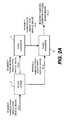
- FIG. 1is a block diagram of a conventional digital still camera system that can employ a conventional sensor and the processing methods of the current invention
- FIG. 2Ais a flow diagram which illustrates the operation of a first embodiment of the dynamic range extender of the present invention where a single first resolution digital image of a scene is captured and converted to a digital image with an extended dynamic range;
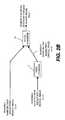
- FIG. 2Bis a flow diagram which illustrates the operation of a second embodiment of the dynamic range extender of the present invention where two digital images of a scene are captured and used to provide a digital image with an extended dynamic range;
- FIG. 3is a diagram of a digital image produced with a Bayer color filter array
- FIG. 4is a diagram of a digital image produced with an electronic image sensor with a Bayer color filter array.
- a digital imageis comprised of one or more digital image channels.
- Each digital image channelis comprised of a two-dimensional array of pixels.
- Each pixel valuerelates to the amount of light received by an electronic image sensor corresponding to the geometrical domain of the pixel.
- a digital imagewill typically consist of red, green, and blue digital image channels. Other configurations, such as using cyan, magenta, and yellow image channels, are also practiced.
- the digital imageconsists of one digital image channel.
- Motion imaging applicationscan be thought of as a time sequence of digital images. Those skilled in the art will recognize that the present invention can be applied to, but is not limited to, a digital image for any of the above-mentioned applications.
- the present inventiondescribes a digital image channel as a two-dimensional array of pixel values arranged by rows and columns, those skilled in the art will recognize that the present invention can be applied to mosaic (non-rectilinear) arrays with equal effect. Those skilled in the art will also recognize that, although the present invention describes replacing an original pixel value with processed pixel values, forming a new digital image with the processed pixel values and retaining the original pixel values is also contemplated.
- Imaging devices employing electronic image sensorsare well known in the art. Therefore, the present description will be directed, in particular, to elements forming part of, or cooperating more directly with, a method in accordance with the present invention. Elements not specifically shown or described herein are selected from those known in the art. Note that as used herein, the term image is a two-dimensional array of pixel values. An image can be a two-dimensional subset of another image. Given the invention as described in the following materials, software not specifically shown, described, or suggested herein, that is useful for implementation of the invention, is conventional and within the ordinary skill in such arts.
- FIG. 1The essential elements employed in the practice of the present invention are shown as a functional block diagram in FIG. 1 .
- an electronic image sensor 3such as a charged-coupled device (CCD) with a color filter array (CFA).
- CCDcharged-coupled device
- CFAcolor filter array
- CMOS devicesmay be used as the electronic image sensor 3 .
- An optical low pass filter 2placed between the lens 1 and the electronic image sensor 3 , performs a slight blurring of the imaged light in order to reduce the occurrence of aliasing.
- Each photosite of the electronic image sensor 3is typically provided with either a red, green, or blue filter, as described by Bayer in commonly assigned U.S. Pat. No. 3,971,065 issued Jul.
- the Bayer arrayis a color filter array in which green filters are located in a checkerboard pattern over the photosites with red and blue filters alternating line by line to fill the interstices of the checkerboard pattern producing twice as many green filter sites as either red or blue filter sites. Note that the method described herein may be easily extended to color filter arrays with different arrangements of the color filters, a different number of color filters, or a different set of color filters.
- An A/D converter 4receives the voltage signal corresponding to the imaged light from the photosites on the electronic imager sensor 3 and produces an image signal corresponding to the voltage signal. Since the electronic image sensor 3 has multiple types of photosites (e.g. red, green, or blue) but produces only a single value at each pixel location, the digital image, as captured, is a sparsely sampled digital image with respect to color.
- the pixel values of the digital image output from the A/D converter 4constitute a sparsely sampled digital image having red, green, and blue pixel values at neighboring pixel locations. The sparsely sampled digital image is then stored in memory 15 .
- the digital image processor 5receives the sparsely sampled digital image from memory 15 , modifies the image signal, and produces a digital image with red, green, and blue values for all pixel locations. It should be noted that the digital image processor 5 can be a programmed personal computer or a microprocessor. The present invention can be practiced in a digital camera, a mobile phone, a film or reflection scanner, or any other device that produces a digital image.
- the digital image processor 5 shown in FIG. 1contains two sub-components: the dynamic range extender 6 and the CFA interpolator 7 .
- the image signalis received from memory 15 , in which the sparsely sampled digital image output from the A/D converter 4 is stored, by the dynamic range extender 6 .
- the dynamic range extender 6processes the sparsely sampled digital image to create a new digital image with extended dynamic range.
- an extended dynamic range digital imageis created from a first digital image by replacing the pixel values in the first digital image where they are very low with processed pixel values from a second digital image that is a lower resolution version of the first digital image.
- the output from the dynamic range extender 6is a sparsely sampled third digital image with areas of both first resolution and lower second resolution.
- the dynamic range extender 6then transmits the extended dynamic range image to the CFA interpolator 7 where the color values are interpolated to provide red, green and blue color values at each pixel.
- the purpose of the CFA interpolator 7is to generate a full description of the color for each pixel location of the sensed photographic image. Any commonly known CFA interpolator can be used, and a description of one CFA interpolator is disclosed in U.S. Pat. No. 5,652,621 issued Jul. 29, 1997 to Adams et al.
- FIG. 2Arepresents the dynamic range extender in the first preferred embodiment of the present invention in which a single sparsely sampled digital image is captured by the electronic image sensor 3 .
- the sparsely sampled digital imageis transmitted from the A/D converter 4 to the digital image processor 5 .
- the dynamic range extender 6comprises an image copier 8 , a pixel combiner 9 , and an image combiner 10 .
- the image copier 8makes a copy of the single sparsely sampled digital image as received from the A/D converter 4 , wherein the pixel values are now named i(x,y), where (x,y) specifies the indices of the signal location with reference to the electronic image sensor 3 , and stores the copy in memory 15 .
- the sparsely sampled digital images produced by the image copier 8are i(x,y) and its copy i′(x,y) as shown in FIG. 2A .
- the image i′(x,y)is transmitted to the pixel combiner 9 , where each pixel is assigned to a pixel sub-array.
- a pixel sub-arrayis defined as an array of pixels that are all of the same type and are located close together.
- the pixel sub-array that is shown in FIG. 3is one row high and three columns wide and is composed of red pixels 11 , 12 , 13 .
- the present inventiondescribes a pixel combiner 9 that uses pixel sub-arrays that are one row high and three columns wide and contain three pixels of the same type, those skilled in the art will recognize that the present invention can be applied using pixel sub-arrays of other dimensions or that contain a different amount of pixels, or that contain pixels of different types with equal effect.
- a pixel sub-arrayis centered on one of the pixels of the sub-array and each pixel in the image belongs to only one pixel sub-array.
- the image represented in FIG. 4has six red sub-arrays that have the same size as the sub-array shown in FIG.
- the image that results after processing all the sub-arrays of image i′(x,y) as described aboveis a low-resolution image that has the same number and type of pixels as i(x,y). Therefore, the output of the pixel combiner 9 is a low resolution sparsely sampled digital image, c(x,y). Since the values of all the pixels in a sub-array are replaced by the same single sum value, the image c(x,y) has a higher signal and relatively less noise than i(x,y).
- the pixels in i(x,y) that have a very low valuewill result in significantly increased values in the corresponding pixels of c(x,y) and the pixels in i(x,y) that have a high value will result in clipped values for the corresponding pixels of c(x,y).
- Both images i(x,y) and c(x,y)are transmitted to the image combiner 10 from memory 15 .
- the combining function f(.,.)is such that the value of a pixel in d(x, y) is approximately equal to the value of the corresponding pixel in i(x,y) when the corresponding pixel in i(x,y) has a high value and the value of a pixel in d(x, y) is approximately equal to the value of the corresponding pixel in c(x,y) when the corresponding pixel in i(x,y) has a low value.
- the combining function f(.,.)is such that the value of a pixel in d(x, y) is equal to some combination of the value of the corresponding pixel in i(x,y) with the corresponding pixel in c(x,y) when the corresponding pixel in i(x,y) has a value that is neither high nor low.
- a low pixel valuecorresponds to a dark area of an image and a high pixel value corresponds to a light area of an image.
- the essential effect of the combining function f(.,.)is to replace dark regions in i(x,y) with corresponding regions from c(x,y) to provide a digital image with extended dynamic range.
- a dark regionis where a majority of the pixels have a digital code value which is less than 50% of the maximum code value.
- the image d(x,y), which is the output of the image combiner 10is a sparsely sampled extended dynamic range image because the dark areas of the scene that result in very low and noisy pixel values in i(x,y) result in higher and relatively less noisy pixel values in d(x,y).
- the image d(x,y)is transmitted to the CFA interpolator 7 to generate a full description of the color for each pixel location of the sensed photographic image.
- an extended dynamic range imageis produced from two or more images.
- the operation of the dynamic range extender 6is more fully explained in FIG. 2B with reference to FIG. 2A .
- two sequential digital imagesare captured by the image sensor 3 and transmitted as sparsely sampled digital images from the A/D converter 4 to memory 15 and then the image processor 5 wherein the dynamic range extender 6 receives the pixel values for the two sparsely sampled digital images as i 1 (x,y) and i 2 (x,y).
- the set of pixels values for the first sparsely sampled digital image i 1 (x,y)is transmitted directly to the image combiner 10 whereas the set of pixel values for the second sparsely sampled digital image i 2 (x,y) is transmitted to the pixel combiner 9 .
- a set of pixel values for a low resolution sparsely sampled digital image c(x,y)is produced by the pixel combiner 9 from the set of pixel values for the second sparsely sampled digital image i 2 (x,y).
- An extended dynamic range digital imageis then produced by the image combiner 10 from the two sets of pixels values i 1 (x,y) and c(x,y).
- This second preferred embodiment of the inventiondescribes how the second digital image is provided from a second capture of the scene with combined pixels.
- the charge from same colored pixelscan be combined or binned as is well known in the image sensor art. Combining or binning charge from two pixels doubles the signal level, while the noise associated with sampling and reading out the combined signal remains the same, thereby increasing the signal to noise ratio by a factor of two, representing a corresponding two times increase in the photosensitivity of the combined pixels.
- the digital representations of the light levels at same colored pixelscan be summed or averaged.
- the voltages corresponding to the measured amounts of charge in same colored pixelscan be averaged by first charging capacitors to the voltages produced by the pixels and then connecting the capacitors together to average the voltages, with the capacitors being of equal sizes to perform a simple average or of differing sizes to perform a weighted average.
- the resulting signalincreases by a factor of two, but the corresponding noise levels from reading the two pixels combine in quadrature, thereby increasing the noise by the square root of two; the resulting signal to noise ratio of the combined pixels therefore increases by the square root of two over the uncombined signals.
- a similar analysisapplies to voltage or digital averaging.
- the present inventiondescribes a method where the dynamic range extender 6 operates before the CFA interpolator 7 , those skilled in the art will recognize that the present invention can be applied to the case where the CFA interpolator 7 operates before the dynamic range extender 6 .
- Lens 2Optical lowpass filter 3
- Electronic image sensor 4A/D converter 5
- Digital image processor 6Dynamic range extender 7
- CFA interpolator 8Image copier 9
- Pixel combiner 10Image combiner 11 A red pixel belonging to the first red sub-array 12 A red pixel belonging to the first red sub-array 13 A red pixel belonging to the first red sub-array 14 A center red pixel 15 Memory
Landscapes
- Engineering & Computer Science (AREA)
- Multimedia (AREA)
- Signal Processing (AREA)
- Physics & Mathematics (AREA)
- General Physics & Mathematics (AREA)
- Theoretical Computer Science (AREA)
- Studio Devices (AREA)
- Image Processing (AREA)
Abstract
Description
d(x,y)=f(i(x,y),c(x,y)). (1)
The combining function f(.,.) is such that the value of a pixel in d(x, y) is approximately equal to the value of the corresponding pixel in i(x,y) when the corresponding pixel in i(x,y) has a high value and the value of a pixel in d(x, y) is approximately equal to the value of the corresponding pixel in c(x,y) when the corresponding pixel in i(x,y) has a low value. The combining function f(.,.) is such that the value of a pixel in d(x, y) is equal to some combination of the value of the corresponding pixel in i(x,y) with the corresponding pixel in c(x,y) when the corresponding pixel in i(x,y) has a value that is neither high nor low. A low pixel value corresponds to a dark area of an image and a high pixel value corresponds to a light area of an image. The essential effect of the combining function f(.,.) is to replace dark regions in i(x,y) with corresponding regions from c(x,y) to provide a digital image with extended dynamic range. A dark region is where a majority of the pixels have a digital code value which is less than 50% of the maximum code value. Although those skilled in the art will recognize that there are many combining functions f(.,.) that can be used in the spirit of the invention, an example for this first preferred embodiment is:
d(x,y)=(1−ewi(x,y))i(x,y)+(ewi(x,y))c(x,y) (2)
where w is a negative constant. The image d(x,y), which is the output of the
| 1 | |
| 2 | |
| 3 | Electronic image sensor |
| 4 | A/D converter |
| 5 | |
| 6 | |
| 7 | |
| 8 | |
| 9 | |
| 10 | Image combiner |
| 11 | A red pixel belonging to the first red sub-array |
| 12 | A red pixel belonging to the first red sub-array |
| 13 | A red pixel belonging to the first red sub-array |
| 14 | A center |
| 15 | Memory |
Claims (6)
d(x,y)=(1−ewi(x,y))i(x,y)+(ewi(x,y))c(x,y)
Priority Applications (4)
| Application Number | Priority Date | Filing Date | Title |
|---|---|---|---|
| US11/460,364US7756330B2 (en) | 2006-07-27 | 2006-07-27 | Producing an extended dynamic range digital image |
| JP2009521790AJP5189092B2 (en) | 2006-07-27 | 2007-07-23 | Generate digital images with extended dynamic range |
| EP07810689AEP2047670A1 (en) | 2006-07-27 | 2007-07-23 | Producing an extended dynamic range digital image |
| PCT/US2007/016556WO2008013770A1 (en) | 2006-07-27 | 2007-07-23 | Producing an extended dynamic range digital image |
Applications Claiming Priority (1)
| Application Number | Priority Date | Filing Date | Title |
|---|---|---|---|
| US11/460,364US7756330B2 (en) | 2006-07-27 | 2006-07-27 | Producing an extended dynamic range digital image |
Publications (2)
| Publication Number | Publication Date |
|---|---|
| US20080025634A1 US20080025634A1 (en) | 2008-01-31 |
| US7756330B2true US7756330B2 (en) | 2010-07-13 |
Family
ID=38720304
Family Applications (1)
| Application Number | Title | Priority Date | Filing Date |
|---|---|---|---|
| US11/460,364Expired - Fee RelatedUS7756330B2 (en) | 2006-07-27 | 2006-07-27 | Producing an extended dynamic range digital image |
Country Status (4)
| Country | Link |
|---|---|
| US (1) | US7756330B2 (en) |
| EP (1) | EP2047670A1 (en) |
| JP (1) | JP5189092B2 (en) |
| WO (1) | WO2008013770A1 (en) |
Cited By (4)
| Publication number | Priority date | Publication date | Assignee | Title |
|---|---|---|---|---|
| US20080055683A1 (en)* | 2006-09-06 | 2008-03-06 | Samsung Electronics Co., Ltd. | Image generation system, method and medium |
| US20100183071A1 (en)* | 2009-01-19 | 2010-07-22 | Segall Christopher A | Methods and Systems for Enhanced Dynamic Range Images and Video from Multiple Exposures |
| US8334911B2 (en) | 2011-04-15 | 2012-12-18 | Dolby Laboratories Licensing Corporation | Encoding, decoding, and representing high dynamic range images |
| US9036042B2 (en) | 2011-04-15 | 2015-05-19 | Dolby Laboratories Licensing Corporation | Encoding, decoding, and representing high dynamic range images |
Families Citing this family (71)
| Publication number | Priority date | Publication date | Assignee | Title |
|---|---|---|---|---|
| US7064740B2 (en)* | 2001-11-09 | 2006-06-20 | Sharp Laboratories Of America, Inc. | Backlit display with improved dynamic range |
| WO2005052673A2 (en)* | 2003-11-21 | 2005-06-09 | Sharp Laboratories Of America, Inc. | Liquid crystal display with adaptive color |
| US7602369B2 (en)* | 2004-05-04 | 2009-10-13 | Sharp Laboratories Of America, Inc. | Liquid crystal display with colored backlight |
| US7532192B2 (en)* | 2004-05-04 | 2009-05-12 | Sharp Laboratories Of America, Inc. | Liquid crystal display with filtered black point |
| US20050248553A1 (en)* | 2004-05-04 | 2005-11-10 | Sharp Laboratories Of America, Inc. | Adaptive flicker and motion blur control |
| US7505018B2 (en)* | 2004-05-04 | 2009-03-17 | Sharp Laboratories Of America, Inc. | Liquid crystal display with reduced black level insertion |
| US8395577B2 (en)* | 2004-05-04 | 2013-03-12 | Sharp Laboratories Of America, Inc. | Liquid crystal display with illumination control |
| US7872631B2 (en)* | 2004-05-04 | 2011-01-18 | Sharp Laboratories Of America, Inc. | Liquid crystal display with temporal black point |
| US7612757B2 (en)* | 2004-05-04 | 2009-11-03 | Sharp Laboratories Of America, Inc. | Liquid crystal display with modulated black point |
| US7777714B2 (en) | 2004-05-04 | 2010-08-17 | Sharp Laboratories Of America, Inc. | Liquid crystal display with adaptive width |
| US7898519B2 (en) | 2005-02-17 | 2011-03-01 | Sharp Laboratories Of America, Inc. | Method for overdriving a backlit display |
| US7525528B2 (en)* | 2004-11-16 | 2009-04-28 | Sharp Laboratories Of America, Inc. | Technique that preserves specular highlights |
| US8050512B2 (en)* | 2004-11-16 | 2011-11-01 | Sharp Laboratories Of America, Inc. | High dynamic range images from low dynamic range images |
| US8050511B2 (en)* | 2004-11-16 | 2011-11-01 | Sharp Laboratories Of America, Inc. | High dynamic range images from low dynamic range images |
| US7473745B2 (en)* | 2005-09-02 | 2009-01-06 | Equistar Chemicals, Lp | Preparation of multimodal polyethylene |
| US9143657B2 (en) | 2006-01-24 | 2015-09-22 | Sharp Laboratories Of America, Inc. | Color enhancement technique using skin color detection |
| US8121401B2 (en)* | 2006-01-24 | 2012-02-21 | Sharp Labortories of America, Inc. | Method for reducing enhancement of artifacts and noise in image color enhancement |
| US8941580B2 (en) | 2006-11-30 | 2015-01-27 | Sharp Laboratories Of America, Inc. | Liquid crystal display with area adaptive backlight |
| US7729602B2 (en)* | 2007-03-09 | 2010-06-01 | Eastman Kodak Company | Camera using multiple lenses and image sensors operable in a default imaging mode |
| US20120320237A1 (en)* | 2011-06-15 | 2012-12-20 | Wei-Ting Liu | Camera with function of removing unwanted object and method thereof |
| CN112911252B (en) | 2012-11-28 | 2023-07-04 | 核心光电有限公司 | Multi-aperture imaging system |
| KR101634516B1 (en) | 2013-06-13 | 2016-06-28 | 코어포토닉스 리미티드 | Dual aperture zoom digital camera |
| JP2016523389A (en) | 2013-07-04 | 2016-08-08 | コアフォトニクス リミテッド | Compact telephoto lens assembly |
| CN108989649B (en) | 2013-08-01 | 2021-03-19 | 核心光电有限公司 | Slim multi-aperture imaging system with autofocus and method of use |
| CN103888689B (en)* | 2014-03-13 | 2017-10-31 | 北京智谷睿拓技术服务有限公司 | Image-pickup method and image collecting device |
| US20150334309A1 (en)* | 2014-05-16 | 2015-11-19 | Htc Corporation | Handheld electronic apparatus, image capturing apparatus and image capturing method thereof |
| US9392188B2 (en) | 2014-08-10 | 2016-07-12 | Corephotonics Ltd. | Zoom dual-aperture camera with folded lens |
| CN112433331B (en) | 2015-01-03 | 2022-07-08 | 核心光电有限公司 | Miniature telephoto lens module and camera using the same |
| CN107407849B (en) | 2015-04-02 | 2018-11-06 | 核心光电有限公司 | Dual Voice Coil Coil Motor Structure in Dual Optical Module Camera |
| CN112394467B (en) | 2015-04-16 | 2023-06-09 | 核心光电有限公司 | Autofocus and Optical Image Stabilization in a Compact Folding Camera |
| CN110687655B (en) | 2015-05-28 | 2022-10-21 | 核心光电有限公司 | Bi-directional stiffness for optical image stabilization and auto-focus in dual aperture digital cameras |
| US10230898B2 (en) | 2015-08-13 | 2019-03-12 | Corephotonics Ltd. | Dual aperture zoom camera with video support and switching / non-switching dynamic control |
| EP3474070B1 (en) | 2015-09-06 | 2020-06-24 | Corephotonics Ltd. | Auto focus and optical image stabilization with roll compensation in a compact folded camera |
| KR102369223B1 (en) | 2015-12-29 | 2022-03-02 | 코어포토닉스 리미티드 | Dual-aperture zoom digital camera with automatic adjustable tele field of view |
| KR102002718B1 (en) | 2016-05-30 | 2019-10-18 | 코어포토닉스 리미티드 | Rotary Ball-Guid Voice Coil Motor |
| KR20240036133A (en) | 2016-06-19 | 2024-03-19 | 코어포토닉스 리미티드 | Frame synchronization in a dual-aperture camera system |
| US10706518B2 (en) | 2016-07-07 | 2020-07-07 | Corephotonics Ltd. | Dual camera system with improved video smooth transition by image blending |
| KR20240051317A (en) | 2016-07-07 | 2024-04-19 | 코어포토닉스 리미티드 | Linear ball guided voice coil motor for folded optic |
| EP3842853B1 (en) | 2016-12-28 | 2024-03-06 | Corephotonics Ltd. | Folded camera structure with an extended light-folding-element scanning range |
| US10884321B2 (en) | 2017-01-12 | 2021-01-05 | Corephotonics Ltd. | Compact folded camera |
| KR102212611B1 (en) | 2017-02-23 | 2021-02-05 | 코어포토닉스 리미티드 | Folded camera lens designs |
| KR102530535B1 (en) | 2017-03-15 | 2023-05-08 | 코어포토닉스 리미티드 | Cameras with panoramic scanning range |
| WO2019048904A1 (en) | 2017-09-06 | 2019-03-14 | Corephotonics Ltd. | Combined stereoscopic and phase detection depth mapping in a dual aperture camera |
| US10951834B2 (en) | 2017-10-03 | 2021-03-16 | Corephotonics Ltd. | Synthetically enlarged camera aperture |
| US11333955B2 (en) | 2017-11-23 | 2022-05-17 | Corephotonics Ltd. | Compact folded camera structure |
| CN114609746A (en) | 2018-02-05 | 2022-06-10 | 核心光电有限公司 | Folding camera device |
| CN113568251B (en) | 2018-02-12 | 2022-08-30 | 核心光电有限公司 | Digital camera and method for providing focus and compensating for camera tilt |
| US10694168B2 (en) | 2018-04-22 | 2020-06-23 | Corephotonics Ltd. | System and method for mitigating or preventing eye damage from structured light IR/NIR projector systems |
| KR20250053984A (en) | 2018-04-23 | 2025-04-22 | 코어포토닉스 리미티드 | An optical-path folding-element with an extended two degree of freedom rotation range |
| CN119919618A (en) | 2018-07-04 | 2025-05-02 | 核心光电有限公司 | Cameras with folded scanning beam path for automotive or surveillance applications |
| CN111316346B (en) | 2018-08-04 | 2022-11-29 | 核心光电有限公司 | Switchable continuous display information system above camera |
| US11635596B2 (en) | 2018-08-22 | 2023-04-25 | Corephotonics Ltd. | Two-state zoom folded camera |
| US11287081B2 (en) | 2019-01-07 | 2022-03-29 | Corephotonics Ltd. | Rotation mechanism with sliding joint |
| EP4224841B1 (en) | 2019-03-09 | 2025-06-25 | Corephotonics Ltd. | Method for dynamic stereoscopic calibration |
| US11368631B1 (en) | 2019-07-31 | 2022-06-21 | Corephotonics Ltd. | System and method for creating background blur in camera panning or motion |
| US11659135B2 (en) | 2019-10-30 | 2023-05-23 | Corephotonics Ltd. | Slow or fast motion video using depth information |
| CN114641983A (en) | 2019-12-09 | 2022-06-17 | 核心光电有限公司 | System and method for obtaining intelligent panoramic image |
| US11949976B2 (en) | 2019-12-09 | 2024-04-02 | Corephotonics Ltd. | Systems and methods for obtaining a smart panoramic image |
| EP4546027A3 (en) | 2020-02-22 | 2025-08-13 | Corephotonics Ltd. | Split screen feature for macro photography |
| EP4097773A4 (en) | 2020-04-26 | 2023-11-01 | Corephotonics Ltd. | TEMPERATURE CONTROL FOR HALL BAR SENSOR CORRECTION |
| CN117372249A (en) | 2020-05-17 | 2024-01-09 | 核心光电有限公司 | Image stitching of full field of view reference images |
| US11770609B2 (en) | 2020-05-30 | 2023-09-26 | Corephotonics Ltd. | Systems and methods for obtaining a super macro image |
| KR102862382B1 (en) | 2020-07-15 | 2025-09-18 | 코어포토닉스 리미티드 | Point of view aberrations correction in a scanning folded camera |
| US11637977B2 (en) | 2020-07-15 | 2023-04-25 | Corephotonics Ltd. | Image sensors and sensing methods to obtain time-of-flight and phase detection information |
| CN118433505A (en) | 2020-07-31 | 2024-08-02 | 核心光电有限公司 | camera |
| WO2022034402A1 (en) | 2020-08-12 | 2022-02-17 | Corephotonics Ltd. | Optical image stabilization in a scanning folded camera |
| KR102696960B1 (en) | 2020-12-26 | 2024-08-19 | 코어포토닉스 리미티드 | Video support in a multi-aperture mobile camera with a scanning zoom camera |
| CN112822413B (en)* | 2020-12-30 | 2024-01-26 | Oppo(重庆)智能科技有限公司 | Shooting preview method, shooting preview device, terminal and computer readable storage medium |
| KR102589548B1 (en) | 2021-03-11 | 2023-10-13 | 코어포토닉스 리미티드 | Pop-out camera system |
| US12007671B2 (en) | 2021-06-08 | 2024-06-11 | Corephotonics Ltd. | Systems and cameras for tilting a focal plane of a super-macro image |
| US12328505B2 (en) | 2022-03-24 | 2025-06-10 | Corephotonics Ltd. | Slim compact lens optical image stabilization |
Citations (12)
| Publication number | Priority date | Publication date | Assignee | Title |
|---|---|---|---|---|
| US3971065A (en) | 1975-03-05 | 1976-07-20 | Eastman Kodak Company | Color imaging array |
| US5235434A (en)* | 1991-06-27 | 1993-08-10 | Polaroid Corporation | Method and apparatus for selectively adjusting the brightness of large regions of an image |
| US5237431A (en)* | 1990-06-19 | 1993-08-17 | Fuji Xerox Co., Ltd. | Image reading apparatus for producing high quality images based on tone correction |
| US5652621A (en) | 1996-02-23 | 1997-07-29 | Eastman Kodak Company | Adaptive color plane interpolation in single sensor color electronic camera |
| US5870505A (en) | 1996-03-14 | 1999-02-09 | Polaroid Corporation | Method and apparatus for pixel level luminance adjustment |
| US6040858A (en) | 1994-11-18 | 2000-03-21 | Canon Kabushiki Kaisha | Method and apparatus for expanding the dynamic range of sensed color images |
| US20030117412A1 (en) | 2001-12-21 | 2003-06-26 | General Electric Company | Method for high dynamic range image construction based on multiple images with multiple illumination intensities |
| US20050013503A1 (en)* | 2003-07-15 | 2005-01-20 | Samsung Electronics Co., Ltd. | Apparatus for image enhancement and method of using the same |
| US6864916B1 (en) | 1999-06-04 | 2005-03-08 | The Trustees Of Columbia University In The City Of New York | Apparatus and method for high dynamic range imaging using spatially varying exposures |
| US20050103977A1 (en) | 2003-11-13 | 2005-05-19 | Alexander Krymski | Pixel signal binning and interpolation in column circuits of a sensor circuit |
| US6943831B2 (en) | 2001-01-24 | 2005-09-13 | Eastman Kodak Company | Method and apparatus to extend the effective dynamic range of an image sensing device and use residual images |
| US20080259181A1 (en)* | 2007-04-18 | 2008-10-23 | Haruo Yamashita | Imaging apparatus, imaging method, integrated circuit, and storage medium |
Family Cites Families (1)
| Publication number | Priority date | Publication date | Assignee | Title |
|---|---|---|---|---|
| JP4021261B2 (en)* | 2002-07-08 | 2007-12-12 | 松下電器産業株式会社 | Image processing device |
- 2006
- 2006-07-27USUS11/460,364patent/US7756330B2/ennot_activeExpired - Fee Related
- 2007
- 2007-07-23JPJP2009521790Apatent/JP5189092B2/ennot_activeExpired - Fee Related
- 2007-07-23WOPCT/US2007/016556patent/WO2008013770A1/enactiveApplication Filing
- 2007-07-23EPEP07810689Apatent/EP2047670A1/ennot_activeWithdrawn
Patent Citations (12)
| Publication number | Priority date | Publication date | Assignee | Title |
|---|---|---|---|---|
| US3971065A (en) | 1975-03-05 | 1976-07-20 | Eastman Kodak Company | Color imaging array |
| US5237431A (en)* | 1990-06-19 | 1993-08-17 | Fuji Xerox Co., Ltd. | Image reading apparatus for producing high quality images based on tone correction |
| US5235434A (en)* | 1991-06-27 | 1993-08-10 | Polaroid Corporation | Method and apparatus for selectively adjusting the brightness of large regions of an image |
| US6040858A (en) | 1994-11-18 | 2000-03-21 | Canon Kabushiki Kaisha | Method and apparatus for expanding the dynamic range of sensed color images |
| US5652621A (en) | 1996-02-23 | 1997-07-29 | Eastman Kodak Company | Adaptive color plane interpolation in single sensor color electronic camera |
| US5870505A (en) | 1996-03-14 | 1999-02-09 | Polaroid Corporation | Method and apparatus for pixel level luminance adjustment |
| US6864916B1 (en) | 1999-06-04 | 2005-03-08 | The Trustees Of Columbia University In The City Of New York | Apparatus and method for high dynamic range imaging using spatially varying exposures |
| US6943831B2 (en) | 2001-01-24 | 2005-09-13 | Eastman Kodak Company | Method and apparatus to extend the effective dynamic range of an image sensing device and use residual images |
| US20030117412A1 (en) | 2001-12-21 | 2003-06-26 | General Electric Company | Method for high dynamic range image construction based on multiple images with multiple illumination intensities |
| US20050013503A1 (en)* | 2003-07-15 | 2005-01-20 | Samsung Electronics Co., Ltd. | Apparatus for image enhancement and method of using the same |
| US20050103977A1 (en) | 2003-11-13 | 2005-05-19 | Alexander Krymski | Pixel signal binning and interpolation in column circuits of a sensor circuit |
| US20080259181A1 (en)* | 2007-04-18 | 2008-10-23 | Haruo Yamashita | Imaging apparatus, imaging method, integrated circuit, and storage medium |
Cited By (16)
| Publication number | Priority date | Publication date | Assignee | Title |
|---|---|---|---|---|
| US9077908B2 (en)* | 2006-09-06 | 2015-07-07 | Samsung Electronics Co., Ltd. | Image generation apparatus and method for generating plurality of images with different resolution and/or brightness from single image |
| US10187586B2 (en) | 2006-09-06 | 2019-01-22 | Samsung Electronics Co., Ltd. | Image generation apparatus and method for generating plurality of images with different resolution and/or brightness from single image |
| US20080055683A1 (en)* | 2006-09-06 | 2008-03-06 | Samsung Electronics Co., Ltd. | Image generation system, method and medium |
| US8773709B2 (en) | 2006-09-06 | 2014-07-08 | Samsung Electronics Co., Ltd. | Image generation system, method, and medium, generating plurality of images with different resolution and brightness from single image |
| US20100183071A1 (en)* | 2009-01-19 | 2010-07-22 | Segall Christopher A | Methods and Systems for Enhanced Dynamic Range Images and Video from Multiple Exposures |
| US8406569B2 (en)* | 2009-01-19 | 2013-03-26 | Sharp Laboratories Of America, Inc. | Methods and systems for enhanced dynamic range images and video from multiple exposures |
| US8508617B2 (en) | 2011-04-15 | 2013-08-13 | Dolby Laboratories Licensing Corporation | Encoding, decoding, and representing high dynamic range images |
| US9036042B2 (en) | 2011-04-15 | 2015-05-19 | Dolby Laboratories Licensing Corporation | Encoding, decoding, and representing high dynamic range images |
| US9271011B2 (en) | 2011-04-15 | 2016-02-23 | Dolby Laboratories Licensing Corporation | Encoding, decoding, and representing high dynamic range images |
| US9654781B2 (en) | 2011-04-15 | 2017-05-16 | Dolby Laboratories Licensing Corporation | Encoding, decoding, and representing high dynamic range images |
| US9819938B2 (en) | 2011-04-15 | 2017-11-14 | Dolby Laboratories Licensing Corporation | Encoding, decoding, and representing high dynamic range images |
| US10027961B2 (en) | 2011-04-15 | 2018-07-17 | Dolby Laboratories Licensing Corporation | Encoding, decoding, and representing high dynamic range images |
| US8334911B2 (en) | 2011-04-15 | 2012-12-18 | Dolby Laboratories Licensing Corporation | Encoding, decoding, and representing high dynamic range images |
| US10264259B2 (en) | 2011-04-15 | 2019-04-16 | Dolby Laboratories Licensing Corporation | Encoding, decoding, and representing high dynamic range images |
| US10511837B2 (en) | 2011-04-15 | 2019-12-17 | Dolby Laboratories Licensing Corporation | Encoding, decoding, and representing high dynamic range images |
| US10992936B2 (en) | 2011-04-15 | 2021-04-27 | Dolby Laboratories Licensing Corporation | Encoding, decoding, and representing high dynamic range images |
Also Published As
| Publication number | Publication date |
|---|---|
| WO2008013770A1 (en) | 2008-01-31 |
| US20080025634A1 (en) | 2008-01-31 |
| EP2047670A1 (en) | 2009-04-15 |
| JP5189092B2 (en) | 2013-04-24 |
| JP2009545233A (en) | 2009-12-17 |
Similar Documents
| Publication | Publication Date | Title |
|---|---|---|
| US7756330B2 (en) | Producing an extended dynamic range digital image | |
| US7602418B2 (en) | Digital image with reduced object motion blur | |
| CN112261391B (en) | Image processing method, camera assembly and mobile terminal | |
| US8823808B2 (en) | Method for improved digital video image quality | |
| US6813046B1 (en) | Method and apparatus for exposure control for a sparsely sampled extended dynamic range image sensing device | |
| JP3946492B2 (en) | How to generate a low resolution image | |
| US8218068B2 (en) | Exposing pixel groups in producing digital images | |
| JP4233257B2 (en) | Method and apparatus for extending the effective dynamic range of an imaging device and use of residual images | |
| US6476865B1 (en) | Sparsely sampled image sensing device with color and luminance photosites | |
| EP1209903B1 (en) | Method and system of noise removal for a sparsely sampled extended dynamic range image | |
| US20080219585A1 (en) | Image Processing Apparatus, Image Apparatus, Image Processing Method, and Computer Program | |
| US6909461B1 (en) | Method and apparatus to extend the effective dynamic range of an image sensing device | |
| JP4246428B2 (en) | Tone scale function generation method | |
| US12309502B2 (en) | Image processing method, camera assembly and mobile terminal | |
| JP2008514134A (en) | Extended effective dynamic range |
Legal Events
| Date | Code | Title | Description |
|---|---|---|---|
| AS | Assignment | Owner name:EASTMAN KODAK COMPANY, NEW YORK Free format text:ASSIGNMENT OF ASSIGNORS INTEREST;ASSIGNORS:BORDER, JOHN N.;MORALES, EFRAIN O.;REEL/FRAME:018012/0240 Effective date:20060727 | |
| FEPP | Fee payment procedure | Free format text:PAYOR NUMBER ASSIGNED (ORIGINAL EVENT CODE: ASPN); ENTITY STATUS OF PATENT OWNER: LARGE ENTITY | |
| AS | Assignment | Owner name:CITICORP NORTH AMERICA, INC., AS AGENT, NEW YORK Free format text:SECURITY INTEREST;ASSIGNORS:EASTMAN KODAK COMPANY;PAKON, INC.;REEL/FRAME:028201/0420 Effective date:20120215 | |
| FEPP | Fee payment procedure | Free format text:PAYOR NUMBER ASSIGNED (ORIGINAL EVENT CODE: ASPN); ENTITY STATUS OF PATENT OWNER: LARGE ENTITY Free format text:PAYER NUMBER DE-ASSIGNED (ORIGINAL EVENT CODE: RMPN); ENTITY STATUS OF PATENT OWNER: LARGE ENTITY | |
| AS | Assignment | Owner name:NPEC INC., NEW YORK Free format text:PATENT RELEASE;ASSIGNORS:CITICORP NORTH AMERICA, INC.;WILMINGTON TRUST, NATIONAL ASSOCIATION;REEL/FRAME:029913/0001 Effective date:20130201 Owner name:FAR EAST DEVELOPMENT LTD., NEW YORK Free format text:PATENT RELEASE;ASSIGNORS:CITICORP NORTH AMERICA, INC.;WILMINGTON TRUST, NATIONAL ASSOCIATION;REEL/FRAME:029913/0001 Effective date:20130201 Owner name:KODAK (NEAR EAST), INC., NEW YORK Free format text:PATENT RELEASE;ASSIGNORS:CITICORP NORTH AMERICA, INC.;WILMINGTON TRUST, NATIONAL ASSOCIATION;REEL/FRAME:029913/0001 Effective date:20130201 Owner name:EASTMAN KODAK COMPANY, NEW YORK Free format text:PATENT RELEASE;ASSIGNORS:CITICORP NORTH AMERICA, INC.;WILMINGTON TRUST, NATIONAL ASSOCIATION;REEL/FRAME:029913/0001 Effective date:20130201 Owner name:FPC INC., CALIFORNIA Free format text:PATENT RELEASE;ASSIGNORS:CITICORP NORTH AMERICA, INC.;WILMINGTON TRUST, NATIONAL ASSOCIATION;REEL/FRAME:029913/0001 Effective date:20130201 Owner name:KODAK AVIATION LEASING LLC, NEW YORK Free format text:PATENT RELEASE;ASSIGNORS:CITICORP NORTH AMERICA, INC.;WILMINGTON TRUST, NATIONAL ASSOCIATION;REEL/FRAME:029913/0001 Effective date:20130201 Owner name:KODAK PORTUGUESA LIMITED, NEW YORK Free format text:PATENT RELEASE;ASSIGNORS:CITICORP NORTH AMERICA, INC.;WILMINGTON TRUST, NATIONAL ASSOCIATION;REEL/FRAME:029913/0001 Effective date:20130201 Owner name:LASER-PACIFIC MEDIA CORPORATION, NEW YORK Free format text:PATENT RELEASE;ASSIGNORS:CITICORP NORTH AMERICA, INC.;WILMINGTON TRUST, NATIONAL ASSOCIATION;REEL/FRAME:029913/0001 Effective date:20130201 Owner name:KODAK AMERICAS, LTD., NEW YORK Free format text:PATENT RELEASE;ASSIGNORS:CITICORP NORTH AMERICA, INC.;WILMINGTON TRUST, NATIONAL ASSOCIATION;REEL/FRAME:029913/0001 Effective date:20130201 Owner name:KODAK PHILIPPINES, LTD., NEW YORK Free format text:PATENT RELEASE;ASSIGNORS:CITICORP NORTH AMERICA, INC.;WILMINGTON TRUST, NATIONAL ASSOCIATION;REEL/FRAME:029913/0001 Effective date:20130201 Owner name:EASTMAN KODAK INTERNATIONAL CAPITAL COMPANY, INC., Free format text:PATENT RELEASE;ASSIGNORS:CITICORP NORTH AMERICA, INC.;WILMINGTON TRUST, NATIONAL ASSOCIATION;REEL/FRAME:029913/0001 Effective date:20130201 Owner name:PAKON, INC., INDIANA Free format text:PATENT RELEASE;ASSIGNORS:CITICORP NORTH AMERICA, INC.;WILMINGTON TRUST, NATIONAL ASSOCIATION;REEL/FRAME:029913/0001 Effective date:20130201 Owner name:CREO MANUFACTURING AMERICA LLC, WYOMING Free format text:PATENT RELEASE;ASSIGNORS:CITICORP NORTH AMERICA, INC.;WILMINGTON TRUST, NATIONAL ASSOCIATION;REEL/FRAME:029913/0001 Effective date:20130201 Owner name:KODAK REALTY, INC., NEW YORK Free format text:PATENT RELEASE;ASSIGNORS:CITICORP NORTH AMERICA, INC.;WILMINGTON TRUST, NATIONAL ASSOCIATION;REEL/FRAME:029913/0001 Effective date:20130201 Owner name:KODAK IMAGING NETWORK, INC., CALIFORNIA Free format text:PATENT RELEASE;ASSIGNORS:CITICORP NORTH AMERICA, INC.;WILMINGTON TRUST, NATIONAL ASSOCIATION;REEL/FRAME:029913/0001 Effective date:20130201 Owner name:QUALEX INC., NORTH CAROLINA Free format text:PATENT RELEASE;ASSIGNORS:CITICORP NORTH AMERICA, INC.;WILMINGTON TRUST, NATIONAL ASSOCIATION;REEL/FRAME:029913/0001 Effective date:20130201 | |
| AS | Assignment | Owner name:INTELLECTUAL VENTURES FUND 83 LLC, NEVADA Free format text:ASSIGNMENT OF ASSIGNORS INTEREST;ASSIGNOR:EASTMAN KODAK COMPANY;REEL/FRAME:030221/0362 Effective date:20130201 | |
| FPAY | Fee payment | Year of fee payment:4 | |
| AS | Assignment | Owner name:MONUMENT PEAK VENTURES, LLC, TEXAS Free format text:ASSIGNMENT OF ASSIGNORS INTEREST;ASSIGNOR:INTELLECTUAL VENTURES FUND 83 LLC;REEL/FRAME:041941/0079 Effective date:20170215 | |
| FEPP | Fee payment procedure | Free format text:MAINTENANCE FEE REMINDER MAILED (ORIGINAL EVENT CODE: REM.) | |
| LAPS | Lapse for failure to pay maintenance fees | Free format text:PATENT EXPIRED FOR FAILURE TO PAY MAINTENANCE FEES (ORIGINAL EVENT CODE: EXP.) | |
| STCH | Information on status: patent discontinuation | Free format text:PATENT EXPIRED DUE TO NONPAYMENT OF MAINTENANCE FEES UNDER 37 CFR 1.362 | |
| FP | Lapsed due to failure to pay maintenance fee | Effective date:20180713 | |
| AS | Assignment | Owner name:MONUMENT PEAK VENTURES, LLC, TEXAS Free format text:RELEASE BY SECURED PARTY;ASSIGNOR:INTELLECTUAL VENTURES FUND 83 LLC;REEL/FRAME:064599/0304 Effective date:20230728 |