US7756319B2 - Optical system for determining the angular position of a radiating point source and method of employing - Google Patents
Optical system for determining the angular position of a radiating point source and method of employingDownload PDFInfo
- Publication number
- US7756319B2 US7756319B2US11/369,988US36998806AUS7756319B2US 7756319 B2US7756319 B2US 7756319B2US 36998806 AUS36998806 AUS 36998806AUS 7756319 B2US7756319 B2US 7756319B2
- Authority
- US
- United States
- Prior art keywords
- detector
- mask
- image
- array
- frequency
- Prior art date
- Legal status (The legal status is an assumption and is not a legal conclusion. Google has not performed a legal analysis and makes no representation as to the accuracy of the status listed.)
- Expired - Lifetime, expires
Links
Images


Classifications
- G—PHYSICS
- G01—MEASURING; TESTING
- G01B—MEASURING LENGTH, THICKNESS OR SIMILAR LINEAR DIMENSIONS; MEASURING ANGLES; MEASURING AREAS; MEASURING IRREGULARITIES OF SURFACES OR CONTOURS
- G01B11/00—Measuring arrangements characterised by the use of optical techniques
- G01B11/26—Measuring arrangements characterised by the use of optical techniques for measuring angles or tapers; for testing the alignment of axes
- G—PHYSICS
- G01—MEASURING; TESTING
- G01S—RADIO DIRECTION-FINDING; RADIO NAVIGATION; DETERMINING DISTANCE OR VELOCITY BY USE OF RADIO WAVES; LOCATING OR PRESENCE-DETECTING BY USE OF THE REFLECTION OR RERADIATION OF RADIO WAVES; ANALOGOUS ARRANGEMENTS USING OTHER WAVES
- G01S3/00—Direction-finders for determining the direction from which infrasonic, sonic, ultrasonic, or electromagnetic waves, or particle emission, not having a directional significance, are being received
- G01S3/78—Direction-finders for determining the direction from which infrasonic, sonic, ultrasonic, or electromagnetic waves, or particle emission, not having a directional significance, are being received using electromagnetic waves other than radio waves
- G01S3/782—Systems for determining direction or deviation from predetermined direction
- G01S3/783—Systems for determining direction or deviation from predetermined direction using amplitude comparison of signals derived from static detectors or detector systems
- G01S3/7835—Systems for determining direction or deviation from predetermined direction using amplitude comparison of signals derived from static detectors or detector systems using coding masks
- G—PHYSICS
- G01—MEASURING; TESTING
- G01S—RADIO DIRECTION-FINDING; RADIO NAVIGATION; DETERMINING DISTANCE OR VELOCITY BY USE OF RADIO WAVES; LOCATING OR PRESENCE-DETECTING BY USE OF THE REFLECTION OR RERADIATION OF RADIO WAVES; ANALOGOUS ARRANGEMENTS USING OTHER WAVES
- G01S11/00—Systems for determining distance or velocity not using reflection or reradiation
- G01S11/12—Systems for determining distance or velocity not using reflection or reradiation using electromagnetic waves other than radio waves
- G—PHYSICS
- G01—MEASURING; TESTING
- G01S—RADIO DIRECTION-FINDING; RADIO NAVIGATION; DETERMINING DISTANCE OR VELOCITY BY USE OF RADIO WAVES; LOCATING OR PRESENCE-DETECTING BY USE OF THE REFLECTION OR RERADIATION OF RADIO WAVES; ANALOGOUS ARRANGEMENTS USING OTHER WAVES
- G01S5/00—Position-fixing by co-ordinating two or more direction or position line determinations; Position-fixing by co-ordinating two or more distance determinations
- G01S5/16—Position-fixing by co-ordinating two or more direction or position line determinations; Position-fixing by co-ordinating two or more distance determinations using electromagnetic waves other than radio waves
Definitions
- the present inventionrelates to methods of employing an optical system for determining the angular position of a radiating point source as well as the system itself.
- the disclosure of the parent application identified aboveis hereby incorporated by reference herein.
- radiation from a point sourcetravels through a mask and onto the surface of a sensor.
- this general conceptis well known, however, the prior art fails to teach or suggest the specific techniques employed by Applicant to accurately measure angular position and distance using such a structure.
- Prior art systemshave used masked or coded apertures placed above multi-element detectors. All of these techniques have attempted to determine the position of a projected pattern on a detector surface by comparing signals from fixed detector elements arranged in a unique pattern or from comparison to fixed reference signals previously stored in a computer.
- the present inventionemploys a transmissivity mask with a plurality of sinusoids of different scale to achieve high image detection resolution, and corresponding high angular resolution.
- U.S. Pat. Nos. 4,193,689 and 4,314,761both to Reymond et al. disclose arrangements for locating radiating point sources including the use of a single axis detector array and an aperture mask containing a slit to project light onto the array.
- a cylinder lensis used, and in the later patent, the cylinder lens is replaced with an aperture that can be shuttered to allow light in from preferred directions.
- three single axis arraysare used, and three cameras are required to compute three planes that intersect to define a point in space.
- the embodiments of the present inventiondiffer from the teachings of the Reymond et al. patents since they include computing means to determine scales and shifts of image components and wherein the mask does not include a single slit.
- U.S. Pat. No. 4,209,780 to Fenimore et al. and U.S. Pat. No. 4,389,633 to Fenimoredisclose the technique of using uniformly redundant arrays for coded aperture imaging. Correlation between mask and image is used to determine a lag function of the received mask pattern. A mosaic pattern is disclosed as yielding results superior to those yielded through the use of a random array.
- the mask and detectorare either one or two dimensional.
- the Fenimore '780 patentonly discloses two dimensional imaging. The present invention differs from the teachings of the Fenimore patents since it does not compare an image to a fixed reference pattern.
- U.S. Pat. No. 4,435,838 to Gourlaydiscloses the concept of imaging planes of various distances in the field of tomographic imaging.
- the Gourlay techniqueimproves the prior art process of selecting various image sizes to correlate with detector response to select a particular depth plane.
- Gourlayteaches the setting of a coded aperture at a distance D/d, where D is the object-to-detector distance and d is the object-to-mask distance, so that the image can be kept at the same magnification, thereby simplifying the correlation process.
- the present inventiondiffers from the teachings of Gourlay and other prior art systems in the field of tomographic imaging, since, in the present invention, various object-to-mask distances or various image sizes are not chosen to select a particular depth, but, instead, the mask image scale is automatically determined using frequency domain techniques.
- the present inventionrelates to methods of employing an optical system for determining angular position of a radiating point source as well as the system itself.
- the present inventionincludes the following interrelated objects, aspects and features:
- the present inventionis disclosed in terms of a preferred embodiment, in which a transmissivity mask is located at a distance from a linear array comprising a detector surface.
- the transmissivity maskconsists of a plurality of frequencies varying in one dimension, e.g., in the Y-axis.
- a point radiating sourceilluminates the mask to cast an image onto the array.
- Computing meansare employed to identify phases of said plurality of frequencies to determine the image scale and shift along the detector array axis.
- Measurement of the phase of the lowest frequency componentis used to determine a coarse position measurement and is also used to measure the particular cycle of the next higher frequency component.
- the phase of the next higher frequency componentis used to determine the detector position to a finer degree.
- the next higher frequency componentis also used to determine the particular cycle of the next higher frequency component as the measurements become finer and more accurate consecutively.
- the mask lengthis longer than the detector to ensure that the detector is fully covered by the pattern for all source positions.
- the phase determination of each of the frequency componentsallows resolving to finer and finer degrees as with a vernier caliper.
- a convenient mathematical encryption of the spectral frequency and phase datauses a 3 digit number (base 5), where each digit defines one of five 72° positions for that spectral component.
- the MSB (Nf 0 )corresponds to the fundamental frequency and the LSB (Nf 2 ) corresponds to the highest frequency component.
- the interpolated residual of the f 2 phaseis included in this result to give a more accurate position along the detector surface.
- the angle of incidence between mask and detectoris determined from the mask to detector height X m and the mask position by:
- ⁇ ra ⁇ ⁇ tan ⁇ ( Y m X m )
- the present inventiondiffers from the invention disclosed in the parent application.
- the parent applicationdiscloses use of a linear detector array wherein optical data is read in a sequential manner.
- the present inventiondoes not employ such an array.
- a patterned detector arrayis employed which, in the preferred embodiment, consists of three separate and parallel arrays that each decode one phase of a particular mask image frequency.
- each of the three detector arraysin the preferred embodiment, consists of only five photodetector elements.
- the coarse arrayconsists of five equally spaced detector elements. This array decodes the fundamental frequency F 0 by sampling five separate phase points of the fundamental image frequency.
- the mid-frequency detector arrayalso has five groups each with five interleaved and sequential detector elements that sample five separate phase points of the five mid-frequency mask image cycles.
- the high frequency arrayconsists of five groups of 25 interleaved and connected detector elements that sample five separate phase points of the 25 high frequency mask image cycles.
- the arrangement of five sample points per cycle, every 72 degrees,is sufficient to measure phase accurately and without sensing other image frequencies.
- the mid-frequency detectoris not sensitive to the fundamental or high frequency mask image.
- the arraycomputes the frequency spectrum at three distinct frequency points F 0 , 5F 0 and 25F 0 .
- the critical high frequency phase detection arrayis “windowed” by shaping the pixels according to a Hann window function. This window function is necessary to facilitate achievement of best accuracy.
- the functions of the F 0 and 5F 0 arraysare merely to establish a coarse or medium resolution position, while the final accuracy of the detector is determined by the high frequency array.
- a unique aspect of the present inventionis that it permits parallel image processing of a relatively low number of channels.
- signal modulationcan be employed to reduce the susceptibility to optical or electromagnetic interference. This is a particularly important attribute in severe environments such as are found in jet cockpits where the full sun interference causes problems with conventional optical systems.
- modulation of 100 Khzis employed so that the system can operate even when facing the sun.
- FIG. 1shows a schematic perspective representation of the spatial relationship between a point source of radiation, a window mask pattern, and a detector.
- FIG. 2shows a front view of the FIG. 1 representation.
- FIG. 3shows a side view of the FIG. 1 representation.
- FIG. 4shows a top view of the FIG. 1 representation.
- FIG. 5shows graphical representations of an analog mask pattern for a first embodiment of the present invention.
- FIG. 6shows an enlarged gray scale image of the mask transmissivity function.
- FIG. 7shows the detector array used to measure the phase of the mask image.
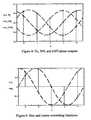
- FIG. 8shows an example of the three detector output signals.
- FIG. 9shows the correlating functions used to determine detector signal phases.
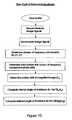
- FIG. 10shows a flowchart of operation of the preferred embodiment.
- FIG. 11shows an enlarged view of the detector array illustrated in FIG. 7 .
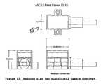
- FIG. 12shows a schematic representation of a two-dimensional angle of incidence embodiment of the present invention.
- FIG. 13shows a top view of the two-dimensional mask of the embodiment of FIG. 12 .
- FIG. 14shows a top view of a two-dimensional detector substrate.
- FIG. 15shows a drawing of jet canopy with optical tracking system and sun interference.
- FIG. 16shows a graph of light transmission versus wavelength for a third embodiment of the present invention consisting of an application in the cockpit of a jet aircraft.
- FIG. 17shows a graph of solar irradiance versus wavelength for the third embodiment of the present invention.
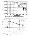
- FIG. 18shows a graph of canopy irradiance versus wavelength for the third embodiment of the present invention.
- FIG. 19shows a graph of canopy transmission, UV filter transmission, and combined transmission.
- a first embodiment of the present inventionis disclosed in detail with reference to FIGS. 1-11 .
- a primary aspect of the first embodiment 10 of the present inventiondescribes a method for determining the angular position of a point source of radiation 11 with respect to a detector 15 by examining the phases of periodic components of the projected image of a variable transmissivity mask 13 .
- the preferred embodimentencodes the transmissivity mask with several frequencies that have logarithmic separations and measures the phases of said frequencies received by the detector.
- the mask image fundamental period (1/f 0 )is made about 1.2% smaller than the detector length (D) to allow for 1.2% magnification at the nominal operating distance of 0.5 meter.
- FIG. 5shows a graphical representation of the constituent mask frequencies f0, 5f0, and 25f0, as well as a graph of the composite function.
- FIG. 6shows an enlargement of the transmissivity mask image of the mask 13 .
- the transmissivity maskis defined by the following equation:
- the detector 15is shown in FIGS. 7 and 11 and comprises three arrays 17 , 19 and 21 with element spacing to detect the fundamental frequency (f0), the fifth harmonic (5f0), and the 25 th harmonic (25f0), respectively.
- the arraysare situated adjacent one another, since the image is one-dimensional and the same optical encoded signal is imaged on each array. It should be noted that, in the preferred embodiment, each array has only five outputs each that sample the sinusoid in five equally separated positions or phases in the sine wave images.
- every fifth elementis connected in parallel, resulting in the summation of similar phase locations from numerous cycles along the wave train image.
- the fifth harmonic detector arraysamples five cycles, while the 25 th harmonic detector array samples 25 cycles.
- Each detector arrayis the same overall length (D).
- the window function applied to the high frequency pixelsis required to prevent aliasing particularly at image magnifications other than unity, which occur at distances other than 0.5 meters.
- the final accuracyis reliant on the phase measurement of the high frequency.
- the window functionis not needed for the lower frequencies, since it does not improve phase accuracy.
- detector array pixelsare in the order of 1 mm in length versus the typical integrated array pixel lengths of 10 um.
- the 100:1 increase in pixel sizeallows reduction of shot noise by the square root of the area ratio, or about 10 times.
- Another benefit of the larger pixelsis the reduction in laser speckle, should a laser be used as a source of emission. Also, the effects of dust and scratches in the optical surfaces are lessened.
- An equally important aspect of this embodimentis the parallel output of detector signals, which allows for signal modulation, thereby eliminating any sensitivity to sun ambient and other forms of lighting interference.
- the signalis modulated at 100 KHz typically to provide this ambient light immunity.
- Another aspect of the preferred embodimentis the use of a refractive medium between mask and detector plane such as fused Silica (Quartz), allowing great stability of the image forming region, and greatly reducing the effects of diffraction at incident angles up to ⁇ 60°.
- a refractive medium between mask and detector planesuch as fused Silica (Quartz)
- the integer number of cycles of the mid frequency componentis computed from the fundamental frequency phase by dividing the phase by 2PI/5 and truncating the remainder.
- the integer number of cycles of the 25 th harmonicis computed is computed from the mid frequency phase by dividing the phase by 2PI/5 and truncating the remainder.
- the overall image displacement or shiftis computed by combining the number of mid frequency cycles, high frequency cycles, and high frequency phase
- ⁇ ra ⁇ ⁇ tan ⁇ ( Y m X m )
- the preferred embodimentuses a refractive medium or window between mask and detector, in which case the angle of incidence in the air path between emitter and mask surface ( ⁇ i ) is computed from the angle of refraction ( ⁇ r ) and the window index of refraction (n w )
- ⁇ ia ⁇ ⁇ sin ⁇ ( sin ⁇ ⁇ ⁇ r n w )
- a second embodiment of the present inventioncomprises two pairs A and B of detectors 15 and masks 13 mounted in quadrature, using a common detector substrate 23 and common mask window 25 to allow two-dimensional sensing of the angle of incidence of an emitter.
- the two-dimensional maskconsists of first and second mask regions that are orthogonal to one another and coplanar.
- the respective detectorsare orthogonal to one another as well.
- FIG. 14shows the detector substrate with two orthogonal and coplanar detectors 15 A and 15 B.
- the advantage of this embodimentis the elimination of detector registration errors, in addition to sensor miniaturization, and the cost savings of using one mask, one detector substrate, one electronic circuit board, and one camera housing.
- the number of processing channels per camerareduces from 15 to 5 making use of multiplexing the low and mid-frequency channels, since their update rates are not required to be as high as the high-frequency channel.
- the two-dimensional sensor sizeis approximately 25 mm L ⁇ 16 mm H ⁇ 8.5 mm H, and the camera housing size is approximately 25 mm L ⁇ 16 mm W ⁇ 20 mm H.
- a third embodiment of the present inventionmay be used to track movements of a pilot's head within a helmet 30 within the cockpit 31 of, for example, a jet aircraft.
- the canopy 33is employed as a filter to remove sunlight from the sun 35 within the bandwidth of the emitter and detector.
- the canopy filtermay be used in conjunction with any radiation-based position and orientation measuring and display system.
- FIG. 15shows the configuration of a jet canopy 33 enclosing an optical helmet tracker system.
- the camera's detector 37measures light from a plurality of helmet-mounted emitters 39 to measure helmet position and orientation. Sunlight from the sun 35 also enters the camera pupil, causing interference and saturation of measurement signals.
- FIG. 16shows a typical canopy transmissivity curve (F16 canopy).
- FIG. 17shows the sun irradiance spectrum (air mass zero), which is an approximate irradiance encountered at flying altitude.
- FIG. 18shows the sun irradiance spectrum as filtered by the jet canopy curve of FIG. 16 .
- the preferred design of this embodimentuses the canopy filter characteristics as one filter to attenuate a portion of the spectrum that overlaps the signal spectrum, and another filter directly covering the detector and filtering sunlight while permitting radiation from the light source 39 to pass therethrough.
- an ultraviolet filteris placed over the detector to accept the emitter spectrum, but reject the portion of sunlight that the canopy transmits.
- FIG. 19shows the spectral transmission curve for a UV band-pass filter, the canopy transmission curve, and the combined transmission curve.
- the UV filter placed over the optical detectorallows almost full transmission of the UV signal, while sunlight must pass through both canopy and UV filter, being attenuated by three orders of magnitude, and having a bandwidth reduced to less than 20 nm.
- the inventioneffectively eliminates any sunlight interference, which has been the bane of optical systems in the jet cockpit environment.
Landscapes
- Physics & Mathematics (AREA)
- General Physics & Mathematics (AREA)
- Electromagnetism (AREA)
- Engineering & Computer Science (AREA)
- Radar, Positioning & Navigation (AREA)
- Remote Sensing (AREA)
- Length Measuring Devices By Optical Means (AREA)
Abstract
Description
Ym=[(Nf0*25+Nf1*5+Nf2)/(125*f0)]
For the fifth harmonic phase:
For the 25th harmonic phase:
Claims (32)
Priority Applications (1)
| Application Number | Priority Date | Filing Date | Title |
|---|---|---|---|
| US11/369,988US7756319B2 (en) | 2002-02-13 | 2006-03-08 | Optical system for determining the angular position of a radiating point source and method of employing |
Applications Claiming Priority (2)
| Application Number | Priority Date | Filing Date | Title |
|---|---|---|---|
| US10/073,335US7027634B2 (en) | 2002-02-13 | 2002-02-13 | Range adaptable system for determining the angular position and distance of a radiating point source and method of employing |
| US11/369,988US7756319B2 (en) | 2002-02-13 | 2006-03-08 | Optical system for determining the angular position of a radiating point source and method of employing |
Related Parent Applications (1)
| Application Number | Title | Priority Date | Filing Date |
|---|---|---|---|
| US10/073,335Continuation-In-PartUS7027634B2 (en) | 2002-02-13 | 2002-02-13 | Range adaptable system for determining the angular position and distance of a radiating point source and method of employing |
Publications (2)
| Publication Number | Publication Date |
|---|---|
| US20060165312A1 US20060165312A1 (en) | 2006-07-27 |
| US7756319B2true US7756319B2 (en) | 2010-07-13 |
Family
ID=46324028
Family Applications (1)
| Application Number | Title | Priority Date | Filing Date |
|---|---|---|---|
| US11/369,988Expired - LifetimeUS7756319B2 (en) | 2002-02-13 | 2006-03-08 | Optical system for determining the angular position of a radiating point source and method of employing |
Country Status (1)
| Country | Link |
|---|---|
| US (1) | US7756319B2 (en) |
Cited By (13)
| Publication number | Priority date | Publication date | Assignee | Title |
|---|---|---|---|---|
| US20100098323A1 (en)* | 2008-07-18 | 2010-04-22 | Agrawal Amit K | Method and Apparatus for Determining 3D Shapes of Objects |
| US8485430B2 (en) | 2011-12-06 | 2013-07-16 | Honeywell International, Inc. | Hand held bar code readers or mobile computers with cloud computing services |
| US8727225B2 (en) | 2012-04-20 | 2014-05-20 | Honeywell International Inc. | System and method for calibration and mapping of real-time location data |
| US8881982B2 (en) | 2012-04-20 | 2014-11-11 | Honeywell Scanning & Mobility | Portable encoded information reading terminal configured to acquire images |
| US9013275B2 (en) | 2012-04-20 | 2015-04-21 | Hand Held Products, Inc. | Portable encoded information reading terminal configured to adjust transmit power level |
| US9041518B2 (en) | 2012-01-26 | 2015-05-26 | Hand Held Products, Inc. | Portable RFID reading terminal with visual indication of scan trace |
| US9064254B2 (en) | 2012-05-17 | 2015-06-23 | Honeywell International Inc. | Cloud-based system for reading of decodable indicia |
| US9092683B2 (en) | 2012-07-10 | 2015-07-28 | Honeywell International Inc. | Cloud-based system for processing of decodable indicia |
| US9443119B2 (en) | 2012-04-20 | 2016-09-13 | Hand Held Products, Inc. | Portable encoded information reading terminal configured to locate groups of RFID tags |
| US9536219B2 (en) | 2012-04-20 | 2017-01-03 | Hand Held Products, Inc. | System and method for calibration and mapping of real-time location data |
| US9558386B2 (en) | 2012-05-15 | 2017-01-31 | Honeywell International, Inc. | Encoded information reading terminal configured to pre-process images |
| US9594939B2 (en) | 2013-09-09 | 2017-03-14 | Hand Held Products, Inc. | Initial point establishment using an image of a portion of an object |
| US9619683B2 (en) | 2014-12-31 | 2017-04-11 | Hand Held Products, Inc. | Portable RFID reading terminal with visual indication of scan trace |
Families Citing this family (9)
| Publication number | Priority date | Publication date | Assignee | Title |
|---|---|---|---|---|
| US8515257B2 (en)* | 2007-10-17 | 2013-08-20 | International Business Machines Corporation | Automatic announcer voice attenuation in a presentation of a televised sporting event |
| RU2399063C1 (en)* | 2008-12-16 | 2010-09-10 | Корпорация "САМСУНГ ЭЛЕКТРОНИКС Ко., Лтд." | Optical source angular position sensor |
| CN102597796B (en) | 2009-06-16 | 2015-02-04 | 百安托国际有限公司 | Two-dimensional position sensing system and its sensor |
| KR20120034205A (en)* | 2009-06-16 | 2012-04-10 | 바안토 인터내셔널 엘티디. | Two-dimensional and three-dimensional position sensing systems and sensors therefor |
| WO2013046100A1 (en)* | 2011-09-28 | 2013-04-04 | Koninklijke Philips Electronics N.V. | Object distance determination from image |
| US8923567B2 (en)* | 2011-12-19 | 2014-12-30 | General Electric Company | Apparatus and method for predicting solar irradiance variation |
| FR2993371B1 (en)* | 2012-07-13 | 2014-08-15 | Thales Sa | OPTICAL ORIENTATION AND POSITION MEASUREMENT SYSTEM WITHOUT PICTURE SOURCE IMAGE FORMATION AND MASK |
| FR3006759B1 (en)* | 2013-06-07 | 2015-06-05 | Thales Sa | OPTICAL ORIENTATION AND POSITION SOURCE MEASUREMENT SYSTEM, CENTRAL MASK, PHOTOSENSITIVE MATRIX SENSOR, AND CUBIC CORNER |
| CN114987796B (en)* | 2022-07-28 | 2022-10-21 | 中国民航大学 | Aircraft cabin display system test system and method based on comprehensive model |
Citations (9)
| Publication number | Priority date | Publication date | Assignee | Title |
|---|---|---|---|---|
| US4193689A (en) | 1977-07-29 | 1980-03-18 | Thomson-Csf | Arrangement for locating radiaring sources |
| US4209780A (en) | 1978-05-02 | 1980-06-24 | The United States Of America As Represented By The United States Department Of Energy | Coded aperture imaging with uniformly redundant arrays |
| US4314761A (en) | 1979-04-06 | 1982-02-09 | Thomson-Csf | Arrangement for locating radiating sources |
| US4389633A (en) | 1980-09-26 | 1983-06-21 | The United States Of America As Represented By The United States Department Of Energy | Coded aperture imaging with self-supporting uniformly redundant arrays |
| US4435838A (en) | 1981-03-30 | 1984-03-06 | International Business Machines Corporation | Method and apparatus for tomographical imaging |
| US5408323A (en) | 1990-10-20 | 1995-04-18 | British Technology Group, Ltd. | Position fixing apparatus with radiation sensor |
| US5640241A (en)* | 1994-02-23 | 1997-06-17 | Kabushikikaisha Wacom | Light spot position measuring method of detecting one-dimensional position by two-dimensional sensor |
| US6141104A (en) | 1997-09-09 | 2000-10-31 | Image Guided Technologies, Inc. | System for determination of a location in three dimensional space |
| US6457169B1 (en)* | 1998-08-25 | 2002-09-24 | International Business Machines Corporation | Geometric phase analysis for overlay measurement |
- 2006
- 2006-03-08USUS11/369,988patent/US7756319B2/ennot_activeExpired - Lifetime
Patent Citations (9)
| Publication number | Priority date | Publication date | Assignee | Title |
|---|---|---|---|---|
| US4193689A (en) | 1977-07-29 | 1980-03-18 | Thomson-Csf | Arrangement for locating radiaring sources |
| US4209780A (en) | 1978-05-02 | 1980-06-24 | The United States Of America As Represented By The United States Department Of Energy | Coded aperture imaging with uniformly redundant arrays |
| US4314761A (en) | 1979-04-06 | 1982-02-09 | Thomson-Csf | Arrangement for locating radiating sources |
| US4389633A (en) | 1980-09-26 | 1983-06-21 | The United States Of America As Represented By The United States Department Of Energy | Coded aperture imaging with self-supporting uniformly redundant arrays |
| US4435838A (en) | 1981-03-30 | 1984-03-06 | International Business Machines Corporation | Method and apparatus for tomographical imaging |
| US5408323A (en) | 1990-10-20 | 1995-04-18 | British Technology Group, Ltd. | Position fixing apparatus with radiation sensor |
| US5640241A (en)* | 1994-02-23 | 1997-06-17 | Kabushikikaisha Wacom | Light spot position measuring method of detecting one-dimensional position by two-dimensional sensor |
| US6141104A (en) | 1997-09-09 | 2000-10-31 | Image Guided Technologies, Inc. | System for determination of a location in three dimensional space |
| US6457169B1 (en)* | 1998-08-25 | 2002-09-24 | International Business Machines Corporation | Geometric phase analysis for overlay measurement |
Cited By (33)
| Publication number | Priority date | Publication date | Assignee | Title |
|---|---|---|---|---|
| US20100098323A1 (en)* | 2008-07-18 | 2010-04-22 | Agrawal Amit K | Method and Apparatus for Determining 3D Shapes of Objects |
| US9223860B2 (en) | 2011-12-06 | 2015-12-29 | Hand Held Products, Inc. | Hand held bar code readers or mobile computers with cloud computing services |
| US8485430B2 (en) | 2011-12-06 | 2013-07-16 | Honeywell International, Inc. | Hand held bar code readers or mobile computers with cloud computing services |
| US8820630B2 (en) | 2011-12-06 | 2014-09-02 | Honeywell International, Inc. | Hand held bar code readers or mobile computers with cloud computing services |
| US9529902B2 (en) | 2011-12-06 | 2016-12-27 | Honeywell International | Hand held bar code readers or mobile computers with cloud computing services |
| US20170011335A1 (en)* | 2012-01-26 | 2017-01-12 | Hand Held Products, Inc. | Portable rfid reading terminal with visual indication of scan trace |
| US9041518B2 (en) | 2012-01-26 | 2015-05-26 | Hand Held Products, Inc. | Portable RFID reading terminal with visual indication of scan trace |
| US9652736B2 (en)* | 2012-01-26 | 2017-05-16 | Hand Held Products, Inc. | Portable RFID reading terminal with visual indication of scan trace |
| US9454685B2 (en) | 2012-01-26 | 2016-09-27 | Hand Held Products, Inc. | Portable RFID reading terminal with visual indication of scan trace |
| US9256853B2 (en) | 2012-01-26 | 2016-02-09 | Hand Held Products, Inc. | Portable RFID reading terminal with visual indication of scan trace |
| US9013275B2 (en) | 2012-04-20 | 2015-04-21 | Hand Held Products, Inc. | Portable encoded information reading terminal configured to adjust transmit power level |
| US10387692B2 (en) | 2012-04-20 | 2019-08-20 | Hand Held Products, Inc. | Portable encoded information reading terminal configured to locate groups of RFID tags |
| US8727225B2 (en) | 2012-04-20 | 2014-05-20 | Honeywell International Inc. | System and method for calibration and mapping of real-time location data |
| US9443119B2 (en) | 2012-04-20 | 2016-09-13 | Hand Held Products, Inc. | Portable encoded information reading terminal configured to locate groups of RFID tags |
| US9652734B2 (en) | 2012-04-20 | 2017-05-16 | Hand Held Products, Inc. | Portable encoded information reading terminal configured to acquire images |
| US9471813B2 (en) | 2012-04-20 | 2016-10-18 | Hand Held Products, Inc. | Portable encoded information reading terminal configured to adjust transmit power level |
| US8881982B2 (en) | 2012-04-20 | 2014-11-11 | Honeywell Scanning & Mobility | Portable encoded information reading terminal configured to acquire images |
| US9536219B2 (en) | 2012-04-20 | 2017-01-03 | Hand Held Products, Inc. | System and method for calibration and mapping of real-time location data |
| US10037510B2 (en) | 2012-04-20 | 2018-07-31 | Hand Held Products, Inc. | System and method for calibration and mapping of real-time location data |
| US10127414B2 (en) | 2012-04-20 | 2018-11-13 | Hand Held Products, Inc. | Portable encoded information reading terminal configured to adjust transmit power level |
| US9165279B2 (en) | 2012-04-20 | 2015-10-20 | Hand Held Products, Inc. | System and method for calibration and mapping of real-time location data |
| US9558386B2 (en) | 2012-05-15 | 2017-01-31 | Honeywell International, Inc. | Encoded information reading terminal configured to pre-process images |
| US11727231B2 (en) | 2012-05-15 | 2023-08-15 | Honeywell International Inc. | Encoded information reading terminal configured to pre-process images |
| US11301661B2 (en) | 2012-05-15 | 2022-04-12 | Honeywell International Inc. | Encoded information reading terminal configured to pre-process images |
| US10885291B2 (en) | 2012-05-15 | 2021-01-05 | Honeywell International Inc. | Encoded information reading terminal configured to pre-process images |
| US9665655B2 (en) | 2012-05-17 | 2017-05-30 | Honeywell International, Inc. | Cloud-based system for reading of decodable indicia |
| US9398008B2 (en) | 2012-05-17 | 2016-07-19 | Honeywell International Inc. | Cloud-based system for reading of decodable indicia |
| US9064254B2 (en) | 2012-05-17 | 2015-06-23 | Honeywell International Inc. | Cloud-based system for reading of decodable indicia |
| US9755703B2 (en) | 2012-07-10 | 2017-09-05 | Honeywell International, Inc. | Cloud-based system for processing of decodable indicia |
| US9092683B2 (en) | 2012-07-10 | 2015-07-28 | Honeywell International Inc. | Cloud-based system for processing of decodable indicia |
| US10025968B2 (en) | 2013-09-09 | 2018-07-17 | Hand Held Products, Inc. | Initial point establishment using an image of a portion of an object |
| US9594939B2 (en) | 2013-09-09 | 2017-03-14 | Hand Held Products, Inc. | Initial point establishment using an image of a portion of an object |
| US9619683B2 (en) | 2014-12-31 | 2017-04-11 | Hand Held Products, Inc. | Portable RFID reading terminal with visual indication of scan trace |
Also Published As
| Publication number | Publication date |
|---|---|
| US20060165312A1 (en) | 2006-07-27 |
Similar Documents
| Publication | Publication Date | Title |
|---|---|---|
| US7756319B2 (en) | Optical system for determining the angular position of a radiating point source and method of employing | |
| US7027634B2 (en) | Range adaptable system for determining the angular position and distance of a radiating point source and method of employing | |
| US6815651B2 (en) | Optical position measurement system employing one or more linear detector arrays | |
| SU1450761A3 (en) | Device for measuring relative displacement of two objects | |
| US6118119A (en) | Spectral analyzer with wavelength and direction indicator | |
| US4969744A (en) | Optical angle-measuring device | |
| US4025197A (en) | Novel technique for spot position measurement | |
| US20120261548A1 (en) | Two-Dimensional Position Sensing Systems and Sensors Therefor | |
| JPH06229781A (en) | Displacement measuring equipment | |
| US7433052B2 (en) | Systems and methods for tilt and range measurement | |
| KR900002116B1 (en) | Spectral analyzer and direction indicator | |
| EP0802396B2 (en) | Inclination sensor and surveying instrument using the same | |
| US6603561B2 (en) | Chromatic diffraction range finder | |
| EP0205551B1 (en) | Spectral analyzer and direction indicator | |
| US6504605B1 (en) | Method and apparatus for determining the coordinates of an object | |
| US3937951A (en) | All-sky photoelectric lightning detector apparatus | |
| US5600123A (en) | High-resolution extended field-of-view tracking apparatus and method | |
| US4577099A (en) | Apparatus for proximity detection of an opaque pattern on a translucent substrate | |
| RU2384812C1 (en) | Autocollimator for measuring angle of torque | |
| RU2116618C1 (en) | Angle meter | |
| EP3825659B1 (en) | Position encoder | |
| EP0271024A2 (en) | Optical focus sensor system | |
| CN107765258B (en) | Optical detection device for judging relative position of reference object or light source | |
| KR980010375A (en) | Digital sun sensor | |
| JP3319666B2 (en) | Edge detection device |
Legal Events
| Date | Code | Title | Description |
|---|---|---|---|
| AS | Assignment | Owner name:ASCENSION TECHNOLOGY CORPORATION, VERMONT Free format text:ASSIGNMENT OF ASSIGNORS INTEREST;ASSIGNOR:ODELL, DON;REEL/FRAME:017666/0636 Effective date:20060308 | |
| STCF | Information on status: patent grant | Free format text:PATENTED CASE | |
| FEPP | Fee payment procedure | Free format text:PAYOR NUMBER ASSIGNED (ORIGINAL EVENT CODE: ASPN); ENTITY STATUS OF PATENT OWNER: LARGE ENTITY | |
| AS | Assignment | Owner name:ROPER ASCENSION ACQUISITION, INC., FLORIDA Free format text:ASSIGNMENT OF ASSIGNORS INTEREST;ASSIGNOR:ASCENSION TECHNOLOGY CORPORATION;REEL/FRAME:028816/0923 Effective date:20120531 Owner name:ASCENSION TECHNOLOGY CORPORATION, FLORIDA Free format text:CHANGE OF NAME;ASSIGNOR:ROPER ASCENSION ACQUISITION, INC.;REEL/FRAME:028816/0920 Effective date:20120531 | |
| FEPP | Fee payment procedure | Free format text:PAT HOLDER NO LONGER CLAIMS SMALL ENTITY STATUS, ENTITY STATUS SET TO UNDISCOUNTED (ORIGINAL EVENT CODE: STOL); ENTITY STATUS OF PATENT OWNER: LARGE ENTITY | |
| FPAY | Fee payment | Year of fee payment:4 | |
| MAFP | Maintenance fee payment | Free format text:PAYMENT OF MAINTENANCE FEE, 8TH YEAR, LARGE ENTITY (ORIGINAL EVENT CODE: M1552) Year of fee payment:8 | |
| AS | Assignment | Owner name:NORTHERN DIGITAL, INC., CANADA Free format text:ASSIGNMENT OF ASSIGNORS INTEREST;ASSIGNOR:ASCENSION TECHNOLOGY CORPORATION;REEL/FRAME:057505/0669 Effective date:20210916 | |
| MAFP | Maintenance fee payment | Free format text:PAYMENT OF MAINTENANCE FEE, 12TH YEAR, LARGE ENTITY (ORIGINAL EVENT CODE: M1553); ENTITY STATUS OF PATENT OWNER: LARGE ENTITY Year of fee payment:12 |