US7755829B2 - Thermally switched reflective optical shutter - Google Patents
Thermally switched reflective optical shutterDownload PDFInfo
- Publication number
- US7755829B2 US7755829B2US12/172,156US17215608AUS7755829B2US 7755829 B2US7755829 B2US 7755829B2US 17215608 AUS17215608 AUS 17215608AUS 7755829 B2US7755829 B2US 7755829B2
- Authority
- US
- United States
- Prior art keywords
- polarizer
- radiant energy
- reflective
- reflective polarizer
- incident
- Prior art date
- Legal status (The legal status is an assumption and is not a legal conclusion. Google has not performed a legal analysis and makes no representation as to the accuracy of the status listed.)
- Expired - Fee Related, expires
Links
Images


Classifications
- E—FIXED CONSTRUCTIONS
- E06—DOORS, WINDOWS, SHUTTERS, OR ROLLER BLINDS IN GENERAL; LADDERS
- E06B—FIXED OR MOVABLE CLOSURES FOR OPENINGS IN BUILDINGS, VEHICLES, FENCES OR LIKE ENCLOSURES IN GENERAL, e.g. DOORS, WINDOWS, BLINDS, GATES
- E06B9/00—Screening or protective devices for wall or similar openings, with or without operating or securing mechanisms; Closures of similar construction
- E06B9/24—Screens or other constructions affording protection against light, especially against sunshine; Similar screens for privacy or appearance; Slat blinds
- G—PHYSICS
- G02—OPTICS
- G02B—OPTICAL ELEMENTS, SYSTEMS OR APPARATUS
- G02B27/00—Optical systems or apparatus not provided for by any of the groups G02B1/00 - G02B26/00, G02B30/00
- G02B27/28—Optical systems or apparatus not provided for by any of the groups G02B1/00 - G02B26/00, G02B30/00 for polarising
- G—PHYSICS
- G02—OPTICS
- G02F—OPTICAL DEVICES OR ARRANGEMENTS FOR THE CONTROL OF LIGHT BY MODIFICATION OF THE OPTICAL PROPERTIES OF THE MEDIA OF THE ELEMENTS INVOLVED THEREIN; NON-LINEAR OPTICS; FREQUENCY-CHANGING OF LIGHT; OPTICAL LOGIC ELEMENTS; OPTICAL ANALOGUE/DIGITAL CONVERTERS
- G02F1/00—Devices or arrangements for the control of the intensity, colour, phase, polarisation or direction of light arriving from an independent light source, e.g. switching, gating or modulating; Non-linear optics
- G02F1/01—Devices or arrangements for the control of the intensity, colour, phase, polarisation or direction of light arriving from an independent light source, e.g. switching, gating or modulating; Non-linear optics for the control of the intensity, phase, polarisation or colour
- G02F1/0136—Devices or arrangements for the control of the intensity, colour, phase, polarisation or direction of light arriving from an independent light source, e.g. switching, gating or modulating; Non-linear optics for the control of the intensity, phase, polarisation or colour for the control of polarisation, e.g. state of polarisation [SOP] control, polarisation scrambling, TE-TM mode conversion or separation
- G—PHYSICS
- G02—OPTICS
- G02F—OPTICAL DEVICES OR ARRANGEMENTS FOR THE CONTROL OF LIGHT BY MODIFICATION OF THE OPTICAL PROPERTIES OF THE MEDIA OF THE ELEMENTS INVOLVED THEREIN; NON-LINEAR OPTICS; FREQUENCY-CHANGING OF LIGHT; OPTICAL LOGIC ELEMENTS; OPTICAL ANALOGUE/DIGITAL CONVERTERS
- G02F1/00—Devices or arrangements for the control of the intensity, colour, phase, polarisation or direction of light arriving from an independent light source, e.g. switching, gating or modulating; Non-linear optics
- G02F1/01—Devices or arrangements for the control of the intensity, colour, phase, polarisation or direction of light arriving from an independent light source, e.g. switching, gating or modulating; Non-linear optics for the control of the intensity, phase, polarisation or colour
- G02F1/0147—Devices or arrangements for the control of the intensity, colour, phase, polarisation or direction of light arriving from an independent light source, e.g. switching, gating or modulating; Non-linear optics for the control of the intensity, phase, polarisation or colour based on thermo-optic effects
- G—PHYSICS
- G02—OPTICS
- G02F—OPTICAL DEVICES OR ARRANGEMENTS FOR THE CONTROL OF LIGHT BY MODIFICATION OF THE OPTICAL PROPERTIES OF THE MEDIA OF THE ELEMENTS INVOLVED THEREIN; NON-LINEAR OPTICS; FREQUENCY-CHANGING OF LIGHT; OPTICAL LOGIC ELEMENTS; OPTICAL ANALOGUE/DIGITAL CONVERTERS
- G02F1/00—Devices or arrangements for the control of the intensity, colour, phase, polarisation or direction of light arriving from an independent light source, e.g. switching, gating or modulating; Non-linear optics
- G02F1/01—Devices or arrangements for the control of the intensity, colour, phase, polarisation or direction of light arriving from an independent light source, e.g. switching, gating or modulating; Non-linear optics for the control of the intensity, phase, polarisation or colour
- G02F1/13—Devices or arrangements for the control of the intensity, colour, phase, polarisation or direction of light arriving from an independent light source, e.g. switching, gating or modulating; Non-linear optics for the control of the intensity, phase, polarisation or colour based on liquid crystals, e.g. single liquid crystal display cells
- G02F1/132—Thermal activation of liquid crystals exhibiting a thermo-optic effect
- G—PHYSICS
- G02—OPTICS
- G02F—OPTICAL DEVICES OR ARRANGEMENTS FOR THE CONTROL OF LIGHT BY MODIFICATION OF THE OPTICAL PROPERTIES OF THE MEDIA OF THE ELEMENTS INVOLVED THEREIN; NON-LINEAR OPTICS; FREQUENCY-CHANGING OF LIGHT; OPTICAL LOGIC ELEMENTS; OPTICAL ANALOGUE/DIGITAL CONVERTERS
- G02F1/00—Devices or arrangements for the control of the intensity, colour, phase, polarisation or direction of light arriving from an independent light source, e.g. switching, gating or modulating; Non-linear optics
- G02F1/01—Devices or arrangements for the control of the intensity, colour, phase, polarisation or direction of light arriving from an independent light source, e.g. switching, gating or modulating; Non-linear optics for the control of the intensity, phase, polarisation or colour
- G02F1/13—Devices or arrangements for the control of the intensity, colour, phase, polarisation or direction of light arriving from an independent light source, e.g. switching, gating or modulating; Non-linear optics for the control of the intensity, phase, polarisation or colour based on liquid crystals, e.g. single liquid crystal display cells
- G02F1/133—Constructional arrangements; Operation of liquid crystal cells; Circuit arrangements
- G02F1/1333—Constructional arrangements; Manufacturing methods
- G02F1/1335—Structural association of cells with optical devices, e.g. polarisers or reflectors
- G02F1/133528—Polarisers
- G02F1/133536—Reflective polarizers
- E—FIXED CONSTRUCTIONS
- E06—DOORS, WINDOWS, SHUTTERS, OR ROLLER BLINDS IN GENERAL; LADDERS
- E06B—FIXED OR MOVABLE CLOSURES FOR OPENINGS IN BUILDINGS, VEHICLES, FENCES OR LIKE ENCLOSURES IN GENERAL, e.g. DOORS, WINDOWS, BLINDS, GATES
- E06B9/00—Screening or protective devices for wall or similar openings, with or without operating or securing mechanisms; Closures of similar construction
- E06B9/24—Screens or other constructions affording protection against light, especially against sunshine; Similar screens for privacy or appearance; Slat blinds
- E06B2009/2464—Screens or other constructions affording protection against light, especially against sunshine; Similar screens for privacy or appearance; Slat blinds featuring transparency control by applying voltage, e.g. LCD, electrochromic panels
- G—PHYSICS
- G02—OPTICS
- G02F—OPTICAL DEVICES OR ARRANGEMENTS FOR THE CONTROL OF LIGHT BY MODIFICATION OF THE OPTICAL PROPERTIES OF THE MEDIA OF THE ELEMENTS INVOLVED THEREIN; NON-LINEAR OPTICS; FREQUENCY-CHANGING OF LIGHT; OPTICAL LOGIC ELEMENTS; OPTICAL ANALOGUE/DIGITAL CONVERTERS
- G02F1/00—Devices or arrangements for the control of the intensity, colour, phase, polarisation or direction of light arriving from an independent light source, e.g. switching, gating or modulating; Non-linear optics
- G02F1/01—Devices or arrangements for the control of the intensity, colour, phase, polarisation or direction of light arriving from an independent light source, e.g. switching, gating or modulating; Non-linear optics for the control of the intensity, phase, polarisation or colour
- G02F1/0136—Devices or arrangements for the control of the intensity, colour, phase, polarisation or direction of light arriving from an independent light source, e.g. switching, gating or modulating; Non-linear optics for the control of the intensity, phase, polarisation or colour for the control of polarisation, e.g. state of polarisation [SOP] control, polarisation scrambling, TE-TM mode conversion or separation
- G02F1/0139—Polarisation scrambling devices; Depolarisers
- G—PHYSICS
- G02—OPTICS
- G02F—OPTICAL DEVICES OR ARRANGEMENTS FOR THE CONTROL OF LIGHT BY MODIFICATION OF THE OPTICAL PROPERTIES OF THE MEDIA OF THE ELEMENTS INVOLVED THEREIN; NON-LINEAR OPTICS; FREQUENCY-CHANGING OF LIGHT; OPTICAL LOGIC ELEMENTS; OPTICAL ANALOGUE/DIGITAL CONVERTERS
- G02F1/00—Devices or arrangements for the control of the intensity, colour, phase, polarisation or direction of light arriving from an independent light source, e.g. switching, gating or modulating; Non-linear optics
- G02F1/01—Devices or arrangements for the control of the intensity, colour, phase, polarisation or direction of light arriving from an independent light source, e.g. switching, gating or modulating; Non-linear optics for the control of the intensity, phase, polarisation or colour
- G02F1/13—Devices or arrangements for the control of the intensity, colour, phase, polarisation or direction of light arriving from an independent light source, e.g. switching, gating or modulating; Non-linear optics for the control of the intensity, phase, polarisation or colour based on liquid crystals, e.g. single liquid crystal display cells
- G02F1/133—Constructional arrangements; Operation of liquid crystal cells; Circuit arrangements
- G02F1/1333—Constructional arrangements; Manufacturing methods
- G02F1/1335—Structural association of cells with optical devices, e.g. polarisers or reflectors
- G02F1/133509—Filters, e.g. light shielding masks
- G02F1/133514—Colour filters
- G—PHYSICS
- G02—OPTICS
- G02F—OPTICAL DEVICES OR ARRANGEMENTS FOR THE CONTROL OF LIGHT BY MODIFICATION OF THE OPTICAL PROPERTIES OF THE MEDIA OF THE ELEMENTS INVOLVED THEREIN; NON-LINEAR OPTICS; FREQUENCY-CHANGING OF LIGHT; OPTICAL LOGIC ELEMENTS; OPTICAL ANALOGUE/DIGITAL CONVERTERS
- G02F1/00—Devices or arrangements for the control of the intensity, colour, phase, polarisation or direction of light arriving from an independent light source, e.g. switching, gating or modulating; Non-linear optics
- G02F1/01—Devices or arrangements for the control of the intensity, colour, phase, polarisation or direction of light arriving from an independent light source, e.g. switching, gating or modulating; Non-linear optics for the control of the intensity, phase, polarisation or colour
- G02F1/13—Devices or arrangements for the control of the intensity, colour, phase, polarisation or direction of light arriving from an independent light source, e.g. switching, gating or modulating; Non-linear optics for the control of the intensity, phase, polarisation or colour based on liquid crystals, e.g. single liquid crystal display cells
- G02F1/133—Constructional arrangements; Operation of liquid crystal cells; Circuit arrangements
- G02F1/1333—Constructional arrangements; Manufacturing methods
- G02F1/1335—Structural association of cells with optical devices, e.g. polarisers or reflectors
- G02F1/133528—Polarisers
- G02F1/133533—Colour selective polarisers
- G—PHYSICS
- G02—OPTICS
- G02F—OPTICAL DEVICES OR ARRANGEMENTS FOR THE CONTROL OF LIGHT BY MODIFICATION OF THE OPTICAL PROPERTIES OF THE MEDIA OF THE ELEMENTS INVOLVED THEREIN; NON-LINEAR OPTICS; FREQUENCY-CHANGING OF LIGHT; OPTICAL LOGIC ELEMENTS; OPTICAL ANALOGUE/DIGITAL CONVERTERS
- G02F1/00—Devices or arrangements for the control of the intensity, colour, phase, polarisation or direction of light arriving from an independent light source, e.g. switching, gating or modulating; Non-linear optics
- G02F1/01—Devices or arrangements for the control of the intensity, colour, phase, polarisation or direction of light arriving from an independent light source, e.g. switching, gating or modulating; Non-linear optics for the control of the intensity, phase, polarisation or colour
- G02F1/13—Devices or arrangements for the control of the intensity, colour, phase, polarisation or direction of light arriving from an independent light source, e.g. switching, gating or modulating; Non-linear optics for the control of the intensity, phase, polarisation or colour based on liquid crystals, e.g. single liquid crystal display cells
- G02F1/133—Constructional arrangements; Operation of liquid crystal cells; Circuit arrangements
- G02F1/1333—Constructional arrangements; Manufacturing methods
- G02F1/1335—Structural association of cells with optical devices, e.g. polarisers or reflectors
- G02F1/133528—Polarisers
- G02F1/133538—Polarisers with spatial distribution of the polarisation direction
Definitions
- the subject matter described hereinrelates to a device for controlling the flow of light and radiant heat through selective reflection.
- the technologyhas particular, but not exclusive, application in passive or active light-regulating and temperature-regulating films, materials and devices, especially as construction materials.
- Photodarkening materialshave been used for decades, for example, in sunglass lenses, to selectively attenuate incoming light when stimulated by ultraviolet (UV) radiation.
- UV radiationWhen incorporated into windows, such materials can be used to regulate the internal temperature of a structure by darkening to attenuate bright sunlight, and by becoming transparent again to allow artificial light or diffuse daylight to pass through unimpeded.
- Such systemsare passive and self-regulating, requiring no external signal other than ambient UV light in order to operate.
- UV lightrather than by temperature
- such systemsare of limited utility in temperature-regulating applications. For example, they may block wanted sunlight in cold weather as well as unwanted sunlight in hot weather.
- Electrodarkening materialshave also been used to regulate the transmission of light.
- the most widely used electrodarkening materialis a liquid crystal sandwiched between two highly efficient absorbing polarizers, which attenuate slightly more than 50% of the light passing through them, primarily by absorption. This material is controlled by an electric field created by coatings of a transparent, electrically conductive material such as indium-tin-oxide (ITO).
- ITOindium-tin-oxide
- Electrodarkening and photodarkening materialsattenuate incoming light primarily through absorption rather than reflection, meaning they will heat up when exposed to bright light. The heat absorbed by these materials may also offset the reductions in radiative transmission, and thus place significant limits on their ability to regulate temperature.
- Wire-grid polarizerswhich reflect infrared light rather than absorbing it, have been used since the 1960s and are described for example in U.S. Pat. No. 4,512,638 to Sriram, et al. With the advent of nanoscale lithography in the 1990s and 2000s, it became possible, though expensive, to produce broadband, wire-grid polarizers that reflect in visible and ultraviolet wavelengths, for use with high-end optics and laser technology as described, for example, in U.S. Pat. No. 6,122,103 to Perkins, et al.
- DBRdistributed Bragg reflector
- Such reflective polarizersare used in video displays to enhance brightness by reflecting the attenuated light back into the device rather than absorbing it as described, for example, in U.S. Pat. No. 7,038,745 to Weber, et al. and U.S. Pat. No. 6,099,758 to Verrall, et al.
- Such reflective polarizerscan exhibit specular reflection for one polarization of light, as in a mirror, or diffuse reflection for one polarization of light, as in a coating of white paint, or a combination of the two.
- reflective polarizerscan be made from certain types of liquid crystals. Whereas wire-grid polarizers and stretched polymer polarizers are linearly polarizing, these liquid crystal polarizers (LCPs) are generally circularly polarizing. Thus, light of one helicity (i.e., right- or left-handed) is transmitted and light of the opposite helicity is reflected.
- LCPsliquid crystal polarizers
- Thermal switchesallow the passage of heat energy in their ON or closed state, but prevent it in their OFF or open state. These switches are mechanical relays, which rely on contact between two conducting surfaces (typically made of metal) to enable the passage of heat. When the two surfaces are withdrawn, heat energy is unable to conduct between them except through the air gap. If the device is placed in vacuum, heat conduction is prevented entirely in the open state.
- Another type of thermal switchinvolves pumping a gas or liquid into or out of a chamber. When the chamber is full, it conducts heat. When empty, there is no conduction, although radiative transfer across the chamber may still occur.
- Lightcan be blocked by optical filters which absorb or reflect certain frequencies of light while allowing others to pass through, thus acting like an optical switch.
- a mechanical shuttercan turn an otherwise transparent material-including a filter-into an optical switch. When the shutter is open, light passes through easily. When the shutter is closed, no light passes.
- an electrodarkening materialsuch as a liquid crystal
- the switchis “nearly solid state,” with no moving parts except photons, electrons, and the liquid crystal molecules themselves.
- electrodarkening materialsdescribed for example in U.S. Pat. No. 7,099,062 to Azens, et al., can serve a similar function.
- These optical filter/switch combinationsare not passive, but must be operated by external signals, e.g., electrical signals.
- Switchable mirrorsare based on reversible metal hydride and metal lithide chemistry, described for example in U.S. Pat. No. 7,042,615 to Richardson. These switchable mirrors rely on the physical migration of ions across a barrier under the influence of an electric field and therefore have limited switching speeds and cycle lifetimes.
- electrically operated “light valves”combine liquid crystals with one or more reflective polarizers as described, for example, in U.S. Pat. No. 6,486,997 to Bruzzone, et al.
- the liquid crystaltypically serves as an electrotropic depolarizer, i.e., as a structure that changes or switches the rotation of the polarity of the light that passes through it on and off under the influence of an electric field.
- the technology disclosed hereinis directed to the temperature-based control over the transmissivity of a window or similar material or structure with regard to radiant energy (e.g., visible, UV, and infrared light), including the entire range of the solar spectrum, for the purpose of regulating the flow of heat into a structure based on external weather conditions, internal temperature, or any combination of the two.
- This technologymay be employed as a device having a temperature-responsive optical depolarizer, for example, a thermotropic liquid crystal) sandwiched between two polarizing filters to regulate the passage of light energy.
- the incident energies passing through this devicewill depend on the reflection and absorption efficiencies of the polarizers used. For example, for polarizers that are very efficient at reflecting radiant energy over the frequency bandwidths of interest.
- TSROSthermally switched reflective optical shutter
- polarizersor polarizers with frequency-dependent efficiencies, may be used to effect percentages of reflection above and below the threshold temperatures that are desirable for aesthetics, energy management, or other reasons. This effect can also be reversed such that the TSROS device is reflective in its cold state, or expanded such that the transmissivity of the TSROS is higher in the transparent state, or retarded such that the reflectivity of the TSROS device is lower in the reflective state.
- two reflective polarizing filterswhich transmit light of a polarization parallel to their own, and reflect (not absorb) light of a perpendicular polarization are arranged in succession.
- the reflective polarizersWhen the reflective polarizers are oriented in parallel, up to 50% of the incoming radiant energy may be reflected. In practice, a small amount is also absorbed, so that typically, the light transmission through two parallel polarizers is 30-40%.
- the reflective polarizersare oriented perpendicular to one another, up to 50% of the light is blocked at one polarizer and up to the remaining 50% transmitted by the first reflective polarizer is blocked by the second reflective polarizer. In this case, transmission of light through both reflective polarizers is very small (often less than 1%) and the majority of the light (often close to 100%) is reflected back in the direction of incidence.
- a switchable depolarizerwhich changes the polarization of the light passing through it, is configured in conjunction with two or more polarizers.
- the switchable polarizermay be a liquid crystal sandwiched between two sheets of transparent, microtextured material such as polymer-coated glass.
- the switchable depolarizermay be specifically selected or designed to be thermochromic, its polarization state shifts at a predetermined temperature. In the “off” state, the polarization state of incoming light is largely unaffected by the depolarizer, and in the “on” state, light of a particular polarization, having passed through the first polarizer, is rotated by a set amount.
- the combination of two reflective polarizing filters and a liquid crystalforms a switchable mirror that reflects either up to 50% or up to 100% of the incoming light, depending on the state of the liquid crystal.
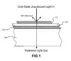
- FIG. 1is a schematic, cross section view of one embodiment of a TRSOS device depicting a layer of thermally sensitive depolarizer material sandwiched between two polarizing filters and attached to a transparent substrate. The action of incoming light is depicted for a cold state of the shutter.
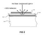
- FIG. 2is a schematic, cross section view of the embodiment of FIG. 1 , except that the action of incoming light is depicted for a hot state of the shutter.
- FIG. 3is a schematic representation of another embodiment of a TSROS device in which the polarizers define apertures or transparent areas to allow some unpolarized light from the external source to pass through the shutter without modification.
- FIG. 4is a schematic representation of an additional embodiment of a TSROS device in which an optional color filter has been included for aesthetic or other reasons.
- FIG. 5is a schematic representation of a further embodiment of a TSROS device, in which the thermotropic depolarizer has been replaced with, or additionally serves as, an electrotropic depolarizer, through the addition of two transparent electrodes and a control system.
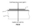
- FIG. 6is a schematic representation of an additional embodiment of a TSROS device, wherein the thermotropic depolarizer has been deleted, and the reflective polarizers themselves are thermotropic. The action of incoming light is depicted for a cold state of the shutter.
- FIG. 7is a schematic representation of the embodiment of FIG. 6 , except that the action of incoming light is depicted for a hot state of the shutter.
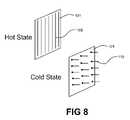
- FIG. 8is a schematic representation of an exemplary thermotropic reflective polarizer in both the hot and cold states.
- FIG. 9is a schematic representation of an additional embodiment of a TSROS device, wherein the first polarizer is a polarity-rotating polarizer.
- FIG. 10is a schematic representation of an exemplary polarity-rotating polarizer, in a cold state.
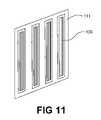
- FIG. 11is a schematic representation of an exemplary photovoltaic polarizer.
- thermotropic optical depolarizermay be used in conjunction with two reflective polarizers to create a thermally switched reflective optical shutter (TSROS) that allows light and radiant energy to pass through the shutter at low temperatures and reflects it away at high temperatures.
- the depolarizeris specifically selected or designed to be thermotropic, i.e., its polarization state shifts at a predetermined temperature.
- the TSROS devicehas particular, but not exclusive, application in regulating the temperatures of buildings, vehicles, or other structures by controlling the amount of solar radiation they absorb.
- thermotropic propertiesincluding liquid crystals, which transition from an ordered or “ON” state (e.g., crystalline, nematic, or smectic) to a disordered or “OFF” state (liquid, isoptropic, or non-polarizing) state at a temperature known as the “clearing point”.
- ONordered or “ON” state
- OFFdisordered or “OFF” state
- CB liquid crystalshave a clearing point of approximately 16.5 degrees centigrade, while 6CB liquid crystals have a clearing point of approximately 29.0 degrees centigrade, and thus “melt” (i.e., become isotropic) under conditions close to room temperature.
- Mixtures of 4CB and 6CBhave a clearing point between these two values, in direct, approximately linear, proportion to the percentage of each component in the mixture.
- the polarization state of incoming lightis largely unaffected by the depolarizer, and in the “on” state, light of a particular polarization, having passed through the first polarizer, is rotated by a set amount (e.g., 45 or 90 degrees, but also 180 or 270 degrees, or other values not divisible by 45).
- a set amounte.g. 45 or 90 degrees, but also 180 or 270 degrees, or other values not divisible by 45.
- the TSROS device in a cold (e.g., crystalline, nematic, or smectic) statereflects up to 50% of the light or other radiant energy that strikes it, and transmits approximately 40%.
- a hot (isotropic) statethe TSROS device reflects up to 100% of the incoming light.
- the opposite transitiona shutter that is reflective when cold and transmissive when hot—is also possible, depending on the exact arrangement of the polarizer and depolarizer layers.
- This technologyhas particular but not exclusive utility as a building or construction material to regulate the flow of radiant energy (including visible, UV, and IR light) through windows, skylights, and other transparent materials based on temperature, thereby restricting the admission of radiant energy (e.g., sunlight) at high temperatures.
- radiant energyincluding visible, UV, and IR light
- this technologycan be used to regulate the internal temperatures of buildings and other structures by controlling the amount of solar radiation they absorb.
- thermodeflectiveis used herein to describe a device or material with variable reflectivity that varies with or is directly controlled by temperature.
- radiation energyis used to refer to visible light, infrared, ultraviolet, radio, microwave, radar, and other wavelengths of electromagnetic radiation that obey the laws of optics.
- lightor optical
- opticalrefers to any effect of a material or device on radiant energy, for example, absorption, reflection, transmission, polarization, depolarization, or diffusion.
- thermotropic depolarizermeans a material in which the depolarization, e.g., rotation of polarization, varies with or is directly controlled by temperature.
- One way to construct a thermotropic depolarizeris to hold thermotropic liquid crystal between two alignment layers. The orientations of the thermotropic liquid crystal molecules are influenced both by the alignment layers, e.g., their chemistry and structure, and the temperature or temperature gradient.
- this structurecan be utilized as a waveblock where the rotation of polarization of various frequencies and bandwidths of light are temperature dependent, and where the crystal-like structure of the waveblock collapses above a threshold temperature. Note that this discussion of thermotropic liquid crystals is provided as an example and should not be considered as limiting the scope of the TSROS device.
- the term “switch”includes both solid-state and mechanical devices for selectively blocking or permitting the flow of energy, and includes both digital switches (e.g., transistors and relays) and analog regulators (e.g., tubes and rheostats). Furthermore, a valve for selectively blocking or regulating the flow of gases or fluids can be considered analogous to a switch so that, in principle, the two terms can be used interchangeably.
- the TSROS deviceis a solid-state optical switch, which moves from its “open” or transmissive state to its “closed” or reflective state based on the temperature of the TSROS device.
- the term “passive”refers to an object or device that responds to environmental conditions but operates independently of external signals or instructions from an operator.
- a devicemay include a number of complex components—even moving parts—and still be regarded as “passive” for the purposes of this document.
- the possible existence of a user override modedoes not alter, in any essential way, the passive nature of such a device.
- an active deviceis one that requires user input in order to perform its normal functions.
- light-sensitive sunglassesare a passive device, whereas a standard light bulb operated by a wall switch or dimmer switch is an active device.
- the term “depolarizer”refers to an object, device, or substance that rotates or otherwise alters the polarization vector of light passing through it in some way other than attenuation.
- the term “polarizer”refers to an object, device, or substance that blocks light of one polarity while transmitting light of orthogonal polarity or, in the case of circularly polarized light, of opposite helicity. Most typically, this blocking occurs by absorption.
- the term “reflective polarizer”refers specifically to a polarizer that blocks light of one polarity by reflecting it rather than by absorbing it. By this definition, a standard absorptive polarizing filter adjacent to a standard reflecting or semi-reflecting filter is not a reflective polarizer and should not be confused with one.
- these polarizersmay be less than 100% efficient (e.g., due to design choice or design and manufacturing limits), be partially absorptive, and have frequency-dependent and spacially dependent reflection, absorption, and transmission characteristics (e.g., due to design choice or design and manufacturing limits) and this should not be construed as limiting the scope of the invention.
- FIG. 1is a schematic, cross section view of one embodiment of a TSROS device depicting a depolarizer layer 102 sandwiched between two reflective polarizing filters 101 and 103 , and attached to an optional transparent substrate 104 .
- the external light sourcewill be unpolarized white light (i.e., light with significant intensity across a significant bandwidth of the visible, near-UV and near-IR spectrum).
- the external light sourceis the sun.
- the devicewill also function when the external light source is not white, as for example a street lamp or the diffuse radiant energy of the blue sky.
- Incoming lightfirst passes through the outer reflective polarizer 101 .
- the reflective polarizer 101include a wire grid polarizer composed of a microscopic array of metal wires affixed to or embedded within a transparent substrate such as glass or plastic, or a polymer-based reflective polarizing film, or a liquid crystal polarizer (LCP), although other forms may also be used.
- wire grid polarizershave the property of polarizing across an extremely broad range of wavelengths, including radio, microwave, and radar wavelengths, which may be particularly useful in some applications.
- the incoming lighte.g., sunlight
- the thermotropic depolarizer 102which is a device or material capable of exhibiting two different polarizing states. In its hot or isotropic or liquid state, the polarized light passing through it is not affected. In its cold (e.g., nematic or crystalline) state, the thermotropic depolarizer 102 rotates the polarization vector of the incoming light by a fixed amount. In the preferred embodiment, the depolarizer 102 is a twisted nematic liquid crystal that rotates the light's polarization vector by 90 degrees. However, a variety of other devices and materials are capable of serving as well, including nematic liquid crystals oriented at 45 degrees, or at some other angle, to the outer reflective polarizer 101 .
- the inner reflective polarizer 103also known as the “analyzer”, where it is either reflected or transmitted, depending on its polarization state.
- the inner reflective polarizer 103is oriented such that its polarization is perpendicular to that of the outer reflective polarizer.
- the light's polarityis perpendicular to that of the inner reflective polarizer 103 , and up to 100% of it is reflected.
- the cold statewhen the light's polarization vector has been rotated by 90 degrees and is parallel to the inner reflective polarizer 103 , some of the light is absorbed by the polarizer material, and the rest is transmitted through.
- the action of incoming lightis depicted for the device's cold state: the outer reflective polarizer 101 reflects up to 50% of the incoming light. The remaining light passes through the thermotropic depolarizer 102 , where its polarization vector is rotated, and then through the inner reflective polarizer or analyzer 103 , where it is largely unaffected. It then passes through an optional transparent substrate 104 , and finally exits the device.
- the deviceserves as a “half mirror” that reflects up to 50% of the light striking its outer surface, absorbs a small amount, and transmits the rest through to the inner surface.
- FIG. 2is a schematic, cross section view of the embodiment of FIG. 1 , except that the action of incoming light is depicted for a hot state of the shutter.
- the thermotropic depolarizer 102does not affect the polarization vector of the light passing through it. Thus, any light striking the inner reflective polarizer is of perpendicular polarity to it, and up to 100% is reflected back.
- the TSROS devicetherefore serves as a “full mirror” that reflects up to 100% of the light striking its outer surface.
- the shutterin its cold state transmits slightly less than half the light energy which strikes its outer surface, whereas in the hot state the shutter transmits substantially less than 1% of the light energy.
- the shuttercan be used to regulate the flow of light or radiant heat into a structure based on the temperature of the shutter.
- the transparent substrate 104is present only for reasons of structural support and convenience. This component may be deleted without significantly altering the function of the shutter. Alternatively, the transparent substrate 104 could be placed on the outer surface of the shutter rather than the inner surface, or transparent substrates 104 could be placed on both surfaces, or even inserted between one or more of the functional layers of the shutter, without significantly altering its function. Furthermore, if the transparent substrate 104 is located on the inside surface of the shutter as shown in FIGS. 1 and 2 , it need not be transparent to all wavelengths, and can in fact be a longpass, shortpass, or bandpass filter as long as the transmitted wavelengths are useful as heat energy, illumination, or for some other purpose. However, for convenience and cost it will generally be preferable to use an ordinary transparent material such as glass or acrylic as the substrate.
- preliminary evidenceindicates that a 50% attenuation of incoming light will appear, subjectively, to be approximately 84% as bright as the original, unattenuated light, but may vary.
- preliminary evidenceindicates a hot state transmission of approximately 10-20% of incident solar energy, and a cold state transmission of 50-70% of incident solar energy are desirable for window applications. Different transmissivity levels may thus be desirable for different uses and embodiments of the TSROS device
- the first stepis to create the liquid crystal (LC) cell or “bottle”.
- Two sheets of SiO 2 -coated (passivated) glassare scribed to a pre-determined size and placed in substrate holders. If there is an indium tin oxide (ITO) low emissivity coating on the glass, it should be etched off, leaving the SiO 2 in place.
- the sheetsare then placed in a 48 KHz ultrasonic cleaner (e.g., Crest Truesweep set at power level 8) for 15 minutes, using a pH neutral soap mixed at 1 oz per gallon of deionized (DI) water (28 Ohm purity or better).
- ITOindium tin oxide
- the sheetsmay be rewashed with Detrex soap. Larger sheets may be cleaned instead using a commercial glass washer (e.g., Billco Series 600).
- the sheetsmay be dried with isopropyl alcohol (IPA) and placed in a drying oven at 80-85 C for 120 minutes or longer as needed for moisture-free storage and staging, and are then placed in an ozone cleaner for 15 minutes.
- a PI alignment layer, dissolved in a solvent,is then deposited by spin coating at 500 RPM for 10 seconds followed by 2000 RPM for 45 seconds. Consistent coating requires approximately 1 ml per square inch of sheet.
- the PI solutionis deposited by inkjet printer. After coating, the substrates are heated to 85 C for 5 minutes to flash away any remaining solvent, and then baked at 180-190 C for 1 hour to harden the PI. The oven door should not be opened until the inside temperature is 85 C or lower.
- sheetsare then stored in a vacuum oven at 50 C until needed.
- the sheetsthen placed in a vacuum fixture to hold it in place, and rubbed with a block of polypropylene or aluminum wrapped with rub cloth material secured with double-sided tape.
- the rub blockis pushed across the surface 25 times in the same direction with no downward pressure other than its own weight.
- the rub directionis then marked (e.g., with a Sharpie pen) on the uncoated side of the sheets.
- a plurality of 7.5-micron spacer beadsare then applied to the rubbed surface of one sheet with an air puff machine, and a second sheet, with rub direction oriented at 90 degrees from the first substrate, is placed rubbed-side-down atop the first sheet.
- the edgesare sealed first with an optical adhesive (e.g., Norlin 68), which does not interact with the liquid crystal, and then with a waterproof sealer (e.g., Loctite 349) leaving at least two ports open, each approximately 1 cm wide.
- An optical adhesivee.g., Norlin 68
- a waterproof sealere.g., Loctite 349
- the Norlin 68is then UV cured with a dose of at least 4000 mJ/cm 2 and either baked for 12 hours at 50 C or else allowed to cure at room temperature for a full week.
- the bottleis then placed in a vacuum loader with a pressure of 20 milliTorr or less and at a temperature below the clearing point and above the freezing of the liquid crystal, and lowered into a slot containing the liquid crystal (e.g., a mixture of 5 parts 6 CB, 1.25 parts E7 and 0.008 parts 811 with a clearing point of 35 C).
- the liquid crystalis drawn into the bottle by capillary action.
- the bottleis removed from the vacuum chamber, the ports are sealed with Norlin 68 and Loctite 349, and the curing step is repeated, taking care to avoid unnecessary exposure of the liquid crystal mixture to UV light.
- the bottleis now complete.
- thermoreflective filtere.g., an LC bottle, polarizers, and UV protection only
- IGUinsulated glass unit
- thermoreflective filterlaminated to one pane.
- the LC bottleis laminated several times with layers of optically clear sheet adhesive (e.g., 3M 8141 and 3M 8142 optically clear adhesive), and reflective polarizer films (e.g., 3M advanced polarizing film (APF) or diffusive polarizing reflective film (DRPF)).
- optically clear sheet adhesivee.g., 3M 8141 and 3M 8142 optically clear adhesive
- reflective polarizer filmse.g., 3M advanced polarizing film (APF) or diffusive polarizing reflective film (DRPF)
- a layer of UV shieldingis then applied (e.g., GamColor 1510 UV film). All lamination steps are performed in a class 10,000 cleanroom environment with a class 1,000 downdraft hood to prevent particulates from causing air bubbles in any of the adhesive layers.
- the processbegins by using a 6 ft automatic/manual roll laminator to begin applying adhesive to the bottle. Using preset increments on the leveling knobs, an elevation is set on the laminator to avoid damaging the bottle. One layer of 3M 8141 is applied to the bottle, followed by a layer of either APF or DRPF. The process is then repeated on the reverse side of the bottle, with the polarizer film at 90° rotation from the previous layer. One more layer of 3M 8141 is applied to either side of the bottle, and then a layer of UV shielding is applied as the last step. At this point, the bottle has become a thermoreflective filter.
- thermoreflective filteris given two consecutive layers of 3M 8142 over the UV shielding.
- Tempered glasstypically larger than the bottle by 1-2 in, is then also given two consecutive layers of 3M 8142.
- the layers on the tempered glassare laminated with tape underneath the border to prevent the 3M 8142 from completely covering the glass.
- the adhesive backingis then removed from both the LC bottle and the tempered glass pane. The adhesive sides of each are placed together and then run through the laminator a final time, again set at an elevation that is suitable for lamination and prevents damaging the bottle.
- the assemblycan now have a standard insulated glass unit built around it.
- Standard aluminum spacers with desiccantare used to separate the two panes of IGU glass and are attached to the glass with PIB bonding beads and sealed around the edges with polyisobutylene (PIB) hot-melt sealant.
- PIBpolyisobutylene
- FIG. 3is a schematic representation of another embodiment of a TSROS device, in which there are gaps 105 in one or both polarizers 101 and 103 to allow some unpolarized light from the external source to pass through the shutter without modification.
- These gaps 105may take the form of holes or stripes, or alternatively the polarizer material itself may be applied in stripes or spots.
- This embodimentmay be useful, for example, in windows that are required to offer a relatively clear, unattenuated view. In this case, the attenuation or obstruction of the polarizers 101 and 103 in the reflective state would be similar to looking through a normal window screen.
- polarizers 101 and 103 with gaps 105increases the transmission of energy through the shutter under all conditions, and thus reduces the ability of the shutter to reflect light and radiant energy in its hot state.
- this arrangementmay be advantageous under circumstances where cold-state transparency is more important than hot-state reflectivity.
- gaps in, or other alterations to, the liquid crystal alignment layercan produce an effect similar to having gaps in the polarizer, and that under some circumstances this may be easier or otherwise more desirable. Also, gaps 105 of any sort can be arranged so that only indirect light is able to pass through the shutter.
- FIG. 4is a schematic representation of an additional embodiment of a TSROS device in which an optional color filter 106 has been added.
- exemplary forms of the color filter 106may include a band reflector (such as a distributed Bragg reflector (DBR) or rugate filter), which is designed to reflect a narrow range of wavelengths and transmit all others, or a bandpass filter (e.g., a sheet of colored glass or plastic), which is designed to transmit a range of wavelengths and reflect or absorb all others.
- DBRdistributed Bragg reflector
- rugate filtere.g., a sheet of colored glass or plastic
- the color filter 106is depicted as being on the exterior surface of the shutter. However, a person of ordinary skill in the art will understand that different aesthetic or optical effects could be created by placing the color filter 106 behind other layers in the shutter. For example, if the color filter 106 were placed on the inner surface of the shutter, then the color would not be apparent to an exterior observer when the shutter was in its hot, or 100% reflective, state.
- a color filterwill reduce the amount of light and radiant energy transmitted through the shutter in its cold, or 50% reflective, state.
- this arrangementmay be advantageous under circumstances where aesthetics, rejection of key wavelengths, or hot-state reflectivity are considered more important than cold-state transparency.
- the shuttercan be used with one or more colored polarizers (i.e., one which does not absorb or reflect across the entire visible spectrum) in place of one of the reflective polarizers.
- One exemplary colored polarizeris the 3M DBEF reflective polarizing film, which yields a magenta color (a combination of red and blue) in the hot or reflective state.
- FIG. 5is a schematic representation of a further embodiment of a TSROS, in which the thermotropic depolarizer 102 has been replaced with, or additionally serves as, an electrotropic depolarizer 102 ′, plus two transparent electrodes 107 and a control system 108 , which collectively perform the same function.
- An exemplary form of the transparent electrodesis a thin layer of indium tin oxide (ITO).
- the control system 108includes a temperature sensor, power supply, and controller hardware.
- An exemplary form of the control system 108is a thermostat and LCD controller consisting of a thermocouple connected to a programmable microcontroller and powered by a small battery or photovoltaic cell.
- the control systemapplies an AC or DC voltage between the transparent electrodes 107 that creates an AC or DC electric field across the electrotropic depolarizer 102 ′, such that its polarization properties are altered (e.g., by reorienting liquid crystal molecules).
- the design of such control systemsis commonplace in the prior art and needs no detailed elaboration herein.
- the operation and use of this embodimentare otherwise identical to operation and use of the embodiment shown in FIGS. 1 and 2 .
- FIG. 6is a schematic representation of an additional embodiment of a TSROS device, wherein the thermotropic depolarizer 102 has been deleted, and the reflective polarizers 101 ′ and 103 ′ are thermotropic.
- the design of the thermotropic reflective polarizers 101 ′ and 103 ′is such that they polarize normally in the hot state, and are minimally polarizing or nonpolarizing in the cold state.
- unpolarized light entering the shutterencounters the outer polarizer 101 ′ in its nonpolarizing state, and is not significantly affected by it, and then encounters the inner thermotropic reflective polarizer 103 ′ in its nonpolarizing state, and is not significantly affected by it either.
- the thermotropic reflective polarizers 101 ′ and 103 ′ in their nonpolarizing stateessentially 100% of the incoming light is transmitted through the shutter.
- FIG. 7is a schematic representation of the embodiment of FIG. 6 in a hot state.
- both thermotropic reflective polarizers 101 ′ and 103 ′are in their fully polarizing configuration, with no depolarizer between them.
- the outer thermotropic reflective polarizer 101 ′up to 50% of it is reflected as in the other embodiments.
- the light that passes throughis of opposite polarity, and therefore up to 100% of it is reflected.
- the shutterin its cold state the shutter is up to 100% transmissive, and in its hot state it is up to 100% reflective.
- this ideal reflectionoccurs when the two thermotropic reflective polarizers 101 ′ and 103 ′ are oriented 90 degrees apart.
- the amount of transmission and reflection in the hot statemay be adjusted by misaligning the two thermotropic reflective polarizers 101 ′ and 103 ′, and the amount of transmission and reflection in the cold state can be adjusted by placing a depolarizer between the two thermotropic reflective polarizers 101 ′ and 103 ′.
- FIG. 8is a schematic representation of an exemplary thermotropic reflective polarizer 101 , in both its hot and cold states.
- the polarizer 101is a wire grid polarizer composed of parallel metal wires 109 .
- the polarizer in this embodimentis a MEMS (microelectrical-mechanical systems) device with wires 109 composed of wire segments 110 made of a conductive, thermotropic material that changes its physical shape in response to temperature. Examples of such materials include, but are not limited to, shape memory alloys such as copper-aluminum-nickel alloy.
- the wire segments 110are formed such that they lie flat at high temperatures, and stand up away from the surface at low temperatures.
- thermotropic reflective polarizersare also possible, including versions composed of liquid crystals or nanoengineered optical and photonic materials or so-called “metamaterials”, and that these or other forms of thermotropic reflective polarizer can be employed in place of the design shown in FIG. 8 without altering the fundamental nature, intent, or functioning of this implementation.
- FIG. 9depicts the operation of this embodiment in the cold state: the polarized light then enters the depolarizer 102 , which is in its cold, organized state (e.g., a twisted nematic state) and thus functions to rotate the polarity of all the light passing through it, to match the polarity of the second polarizer or analyzer 103 , which is a standard reflective polarizer as in other embodiments previously described. Since the depolarized light matches the polarity of the second polarizer 103 , it is transmitted through. Therefore, in this embodiment the TSROS device is up to 100% transmissive in the cold state.
- the depolarizer 102which is in its cold, organized state (e.g., a twisted nematic state) and thus functions to rotate the polarity of all the light passing through it, to match the polarity of the second polarizer or analyzer 103 , which is a standard reflective polarizer as in other embodiments previously described. Since the depolarized light matches the polarity of the
- the depolarizer 102In the hot state, the depolarizer 102 becomes disorganized (i.e., the liquid or isotropic state) and does not affect the polarity of the light passing through it. Therefore, since the light is of opposite polarity to the second polarizer 103 , up to 100% of the light is reflected back. Thus, the TSROS device is up to 100% reflective in its hot state.
- FIG. 10is a schematic representation of an exemplary form of a polarity-rotating polarizer device, consisting of a wire grid polarizer 111 , a mirror 112 , and a depolarizer 113 .
- a polarity-rotating polarizer deviceconsisting of a wire grid polarizer 111 , a mirror 112 , and a depolarizer 113 .
- the polarizer 111When light of matching polarity strikes the polarizer 111 , it is transmitted through. However, when light of opposite polarity strikes the polarizer 111 , it is reflected at a 45-degree angle to the mirror 112 , which also reflects it at a 45-degree angle such that the light is traveling once again in its original direction.
- the reflected lightpasses through a permanent depolarizer (also known as a waveblock or waveplate) that rotates its polarity by a specific amount (usually 90 degrees).
- the polarity of the reflected lightnow matches the polarity of
- FIG. 11is a schematic representation of still another type of reflective polarizer, a photovoltaic polarizer, wherein, the conductive wires 109 of a wire grid polarizer 111 have been replaced with photovoltaic strips.
- these strips 109are Shotkey-type diodes consisting of a thin film of metal (e.g., aluminum) on top of a thin film of semiconductor (e.g., silicon).
- metale.g., aluminum
- semiconductore.g., silicon
- other photovoltaic materials or devicescould be substituted with no essential change to the nature or functioning of this embodiment of a TSROS device.
- one or more photovoltaic polarizerscan be employed in the present implementation, such that a portion of the light blocked by the polarizer or polarizers can be exploited in the form of electrical power. This occurs in addition to the normal thermoreflective behaviors of the shutter.
- a TSROS deviceis passive, self-regulating—requiring no external signals or user inputs in order to function and thus may be considered a so-called “smart material.”
- the TSROS devicemay also be understood as a nearly-solid-state optical switch.
- the switchcontains no moving parts, other than photons and electrons.
- the TSROS deviceregulates, based on temperature, the amount of light and radiant energy that passes through it. The shutter can thereby be used to help regulate the internal temperatures of buildings, vehicles, and other structures by controlling the reflection and absorption of solar energy or other incident light energy
- the TSROS devicemay have multiple configurations. For example, if the TSROS device is configured to transmit and reflect diffuse visible light, it may serve as an aesthetic, energy-regulating replacement for translucent building materials such as glass block, privacy glass, and textured polymers. Alternatively, if the TSROS device is configured to transmit and reflect collimated visible light with little diffusion, it serves as an aesthetic, energy-regulating replacement for transparent building materials such as glass or polymer windows. Further, if the TSROS device is configured to show reflection or transmission peaks in the visible spectrum, it may serve as an energy-regulating replacement for stained glass, tinted windows or window appliqués and coatings, or colored artificial light sources.
- the physical instantiation of a TSROS devicemay be thick or thin, strong or weak, rigid or flexible, monolithic or made up of separate parts, without altering its basic function in any significant way.
- TSROS devicethat is up to 50% reflective, 40% transmissive, and 10% absorptive in its cold state, and up to 50% reflective, 50% absorptive, and less than 1% transmissive in its hot state.
- TSROS devicewould absorb heat in its hot state, and thus would not block heat as effectively. Nevertheless, this arrangement might be advantageous if, for example, the cost of the TSROS device is considered more important than its performance.
- TSROS deviceit is possible to enhance the performance of a TSROS device by improving its cold-state light transmission, reflection, or absorption, by increasing or decreasing its thermal conductivity and/or thermal capacity. Furthermore, it is possible to increase the transparency of the TSROS device in both the cold and hot states by adjusting the structure of one or both polarizing layers (e.g., by alternating stripes or spots of polarizer material with transparent material). It is possible to increase or decrease the transparency of the TSROS device in the hot state, though not in the cold state, by adjusting the orientation of the polarizers with respect to one another (i.e., less than 90 degrees will produce less than 100% reflectivity in the hot state).
- TSROS deviceit is also possible to increase or decrease the transparency of the TSROS device in the cold state by adjusting the rotation of polarized light provided by the depolarizer.
- the TSROS deviceis also functionally enhanced for certain applications through the addition of optional features such as anti-reflection coatings, low-emissivity coatings, concentrating lenses, air gaps or vacuum gaps, phase change materials, or translucent thermal insulators including but not limited to foamed glass and silica aerogels.
- polarizer typesincluding but not limited to wire grid polarizers, stretched polymer polarizers, liquid crystal polarizers, absorptive polarizers, specular reflective polarizers, diffuse reflective polarizers, thermotropic polarizers whose function changes with temperature, and polarity-rotating polarizers
- the reflective polarizersmay be selected such that each has a different polarizing nature, e.g., the polarizing natures could be opposing as specular vs. diffusive or reflective vs. absorptive, at different frequencies.
- the addition of color filter layerscan alter the transmission spectrum (i.e., the color) of the light passing through the TSROS device, for aesthetic or other reasons.
- the resulting optical propertiesdo not closely resemble those of any other building material, although they may bear a passing resemblance to certain types of sunglasses.
- spectrally selective polarizersthat operate only over a particular range (or multiple ranges) of wavelengths, as well as polarizers which have different polarization efficiencies and degrees of absorptivity and reflectivity over particular ranges (or multiple ranges) or wavelengths.
- TSROS devicemay be rigid, there is no requirement for rigidity in order for it to perform the functions described herein. Furthermore, while the various components of the TSROS device are shown and described as being attached or in direct physical contact, the TSROS device will also function if the components are merely adjacent but physically separate.
- the TSROS devicecan be embodied as a solid object (e.g., a window, glass block, spandrel, or movable panel) or group of solid objects (e.g., components affixed to an optical workbench), it can also be embodied as a flexible object such as, for example, a tent material, blanket, curtain, or an appliqué film which can be applied to the surface of glass windows, spandrels, or glass block building materials.
- a solid objecte.g., a window, glass block, spandrel, or movable panel
- group of solid objectse.g., components affixed to an optical workbench
- a flexible objectsuch as, for example, a tent material, blanket, curtain, or an appliqué film which can be applied to the surface of glass windows, spandrels, or glass block building materials.
- the devicemay include features designed to enhance its thermal insulation properties including but not limited to air gaps, vacuum gaps, foams, beads, fiber pads, or aerogels. It may also include features designed to improve thermal sensing, response, and transition temperature accuracy capabilities, such as conductive adhesives, materials with large or small thermal masses, and phase change materials. It may be thick and rigid enough to serve as a structural component of vehicles or building walls. It may be wrapped around or formed upon complex surfaces. It may be aesthetically enhanced with color, or it may be camouflaged to resemble more conventional building materials. Thermochromic pigments may be added to certain surfaces to indicate when they are hot or cold.
- Additivese.g., chiral liquid crystal may be included in the thermotropic depolarizer to set a preferred direction of rotation of polarized light. This may improve the speed and optical properties of the transition between states.
- a solvente.g., Merck liquid crystal solvent ZLI1132
- additivesmay be included in the depolarizer, for example, to improve the temperature stability of transitions or to reduce the susceptibility of the depolarizer to light or energy of particular wavelengths or ranges of wavelengths to reduce chemical susceptibility to breakdown due to UV light, to prevent the absorption of certain wavelengths of light and conversion into heat, or to mitigate changes in transition temperatures due to chemical breakdown of other components).
- hexane and chloroformmay be introduced to adjust the freezing temperature or lower viscosity.
- Mechanical enhancementsmay be added to reorient components, either to face them toward or away from incoming light, or to alter their wavelength response or apparent thickness.
- the exact arrangement of the various layerscan be different than is depicted here, and (depending on the materials and wavelengths selected) different layers can be combined as single layers, objects, devices, or materials, without altering the essential structure and function of a TSROS device.
- the description abovecontains many specificities, these should not be construed as limiting the scope of the invention but rather construed as merely providing illustrations of certain exemplary embodiments of this invention.
- the TSROC deviceof different materials, and in different configurations.
- the structurecould be inflatable or could be optimized for use underwater or in outer space instead of in normal air.
- the TSROS devicecould incorporate one or more additional polarizers, whether parallel or rotated at some angle to one another and to the original two polarizers, in order to modify the polarization state of light at various positions within the TSROS device.
- additional polarizerswhether parallel or rotated at some angle to one another and to the original two polarizers, in order to modify the polarization state of light at various positions within the TSROS device.
- not all of the polarizerswill necessarily be reflective polarizers, although at least one must be.
- Numerous combinations of polarizer angle and liquid crystal molecule orientationcan be used to produce different optical effects (e.g., reflective when cold instead of reflective when hot, different colors in the transmissive state, etc.).
- the depolarizercan employ a wide variety of different combinations of nematic, twisted nematic, smectic, solid/crystalline, discotic, chiral, and other physical/molecular states, as well as alternative liquid crystal technologies such as polymer stabilized cholesterics, and guest-host cells, with or without electric fields, textured surfaces, internal guide wires, or other means to reorient the component molecules.
- depolarizerswhich are diffusive in the cold state and specular in the hot state (and reverse), are opalescent in one or both states, change the color balance of the transmitted and reflected light differently as the temperature changes, and similarly have different color balances when in the hot and cold state.
- reflections from the TSROS devicecan be sent in any direction, or can be diffused to limit the blinding “second sun” effect that sometimes occurs near large, mirrored surfaces.
- polarizersthat act on any of the various polarizations of light, (e.g. circular, elliptical, and linear). Such embodiments are explicitly claimed as part of the present invention.
- the depolarizer or one or more polarizerscould be mechanical in nature, physically rotating by 90 degrees (or by some other amount) in response to a shift in temperature.
- the thermotropic depolarizercould be designed such that its temperature affected the range of wavelengths over which it operated, rather than (or in addition to) affecting its ability to depolarize.
- a waveblock made from a material with very high coefficient of thermal expansionwould have this property.
- Any or all of the layers in the devicecould be composed of doped, nanostructured, or microstructured materials including but not limited to custom photonic crystals.
- One or more layerscould be non-planar in shape (e.g., parabolic mirrors formed from reflective polarizers), or other shaped reflectors or similar devices could be incorporated, to help concentrate, diffuse, or otherwise affect incoming light from a variety of angles.
- TSROS deviceas a thermally-regulating building material may be enhanced by careful positioning of the device, for example by placing it under the eave on the south face of a house so that the device is in full sunlight during winter days and is shadowed by the eave on summer days when the sun is higher in the sky.
- itcan be used in place of traditional skylights, or as a panel or appliqué affixed to ordinary glass windows or glass blocks.
- a TSROS devicecan be used to display temperature-controlled reflective images.
- imagesincluding text, line drawings, corporate logos, and monochromatic photographs, can be produced by arranging thermoreflective materials in the shape of the desired image, or by selectively varying the temperature response of the thermoreflective materials in particular areas so that the image appears at particular temperature or range of temperatures, or by manipulating liquid crystal alignment layers or other molecular alignment processes such that the material's thermoreflective response is enhanced or reduced in particular areas to form the image, or by other methods which do not fundamentally alter the nature of the image or its underlying technology.
- Such imagescan include reflective optical components such as mirrors, half-mirrors, gratings, grids, and fresnel lenses, such that the thermoreflective material or device exhibits markedly different optical properties at high temperature than at low temperature.
- All directional referencese.g., proximal, distal, upper, lower, inner, outer, upward, downward, left, right, lateral, front, back, top, bottom, above, below, vertical, horizontal, clockwise, and counterclockwise are only used for identification purposes to aid the reader's understanding of the present invention, and do not create limitations, particularly as to the position, orientation, or use of the invention.
- Connection referencese.g., attached, coupled, connected, and joined are to be construed broadly and may include intermediate members between a collection of elements and relative movement between elements unless otherwise indicated. As such, connection references do not necessarily imply that two elements are directly connected and in fixed relation to each other.
Landscapes
- Physics & Mathematics (AREA)
- Nonlinear Science (AREA)
- Optics & Photonics (AREA)
- General Physics & Mathematics (AREA)
- Crystallography & Structural Chemistry (AREA)
- Chemical & Material Sciences (AREA)
- Engineering & Computer Science (AREA)
- Structural Engineering (AREA)
- Mathematical Physics (AREA)
- Architecture (AREA)
- Civil Engineering (AREA)
- Liquid Crystal (AREA)
- Polarising Elements (AREA)
Abstract
Description
Claims (55)
Priority Applications (4)
| Application Number | Priority Date | Filing Date | Title |
|---|---|---|---|
| US12/172,156US7755829B2 (en) | 2007-07-11 | 2008-07-11 | Thermally switched reflective optical shutter |
| US12/830,068US8072672B2 (en) | 2007-07-11 | 2010-07-02 | Thermally switched reflective optical shutter |
| US13/311,212US8755105B2 (en) | 2007-07-11 | 2011-12-05 | Thermally switched reflective optical shutter |
| US14/307,274US20150070746A1 (en) | 2007-07-11 | 2014-06-17 | Thermally switched reflective optical shutter |
Applications Claiming Priority (3)
| Application Number | Priority Date | Filing Date | Title |
|---|---|---|---|
| US95909607P | 2007-07-11 | 2007-07-11 | |
| US1558907P | 2007-12-20 | 2007-12-20 | |
| US12/172,156US7755829B2 (en) | 2007-07-11 | 2008-07-11 | Thermally switched reflective optical shutter |
Related Child Applications (1)
| Application Number | Title | Priority Date | Filing Date |
|---|---|---|---|
| US12/830,068ContinuationUS8072672B2 (en) | 2007-07-11 | 2010-07-02 | Thermally switched reflective optical shutter |
Publications (2)
| Publication Number | Publication Date |
|---|---|
| US20090015902A1 US20090015902A1 (en) | 2009-01-15 |
| US7755829B2true US7755829B2 (en) | 2010-07-13 |
Family
ID=40229101
Family Applications (4)
| Application Number | Title | Priority Date | Filing Date |
|---|---|---|---|
| US12/172,156Expired - Fee RelatedUS7755829B2 (en) | 2007-07-11 | 2008-07-11 | Thermally switched reflective optical shutter |
| US12/830,068Expired - Fee RelatedUS8072672B2 (en) | 2007-07-11 | 2010-07-02 | Thermally switched reflective optical shutter |
| US13/311,212Expired - Fee RelatedUS8755105B2 (en) | 2007-07-11 | 2011-12-05 | Thermally switched reflective optical shutter |
| US14/307,274AbandonedUS20150070746A1 (en) | 2007-07-11 | 2014-06-17 | Thermally switched reflective optical shutter |
Family Applications After (3)
| Application Number | Title | Priority Date | Filing Date |
|---|---|---|---|
| US12/830,068Expired - Fee RelatedUS8072672B2 (en) | 2007-07-11 | 2010-07-02 | Thermally switched reflective optical shutter |
| US13/311,212Expired - Fee RelatedUS8755105B2 (en) | 2007-07-11 | 2011-12-05 | Thermally switched reflective optical shutter |
| US14/307,274AbandonedUS20150070746A1 (en) | 2007-07-11 | 2014-06-17 | Thermally switched reflective optical shutter |
Country Status (8)
| Country | Link |
|---|---|
| US (4) | US7755829B2 (en) |
| EP (1) | EP2171520A4 (en) |
| JP (1) | JP5558350B2 (en) |
| KR (1) | KR101265393B1 (en) |
| CN (2) | CN102967961B (en) |
| AU (1) | AU2008274933B2 (en) |
| CA (3) | CA2970259C (en) |
| WO (1) | WO2009009770A1 (en) |
Cited By (40)
| Publication number | Priority date | Publication date | Assignee | Title |
|---|---|---|---|---|
| US20090167971A1 (en)* | 2007-12-20 | 2009-07-02 | Ravenbrick, Llc | Thermally switched absorptive window shutter |
| US20090219603A1 (en)* | 2007-05-18 | 2009-09-03 | Jiuzhi Xue | Temperature activated optical films |
| US20090268273A1 (en)* | 2008-04-23 | 2009-10-29 | Ravenbrick Llc | Glare Management of Reflective and Thermoreflective Surfaces |
| US20100244495A1 (en)* | 2009-03-27 | 2010-09-30 | Gm Global Technology Operations, Inc. | Phase change material usage in window treatments |
| US20100271686A1 (en)* | 2007-07-11 | 2010-10-28 | Ravenbrick Llc | Thermally switched reflective optical shutter |
| US20110025934A1 (en)* | 2009-04-10 | 2011-02-03 | Ravenbrick Llc | Thermally switched optical filter incorporating a refractive optical structure |
| US20110216254A1 (en)* | 2007-01-24 | 2011-09-08 | Ravenbrick Llc | Thermally Switched Optical Downconverting Filter |
| US8102478B2 (en) | 2005-03-15 | 2012-01-24 | Serious Energy, Inc. | Windows with electrically controllable transmission and reflection |
| RU2465181C2 (en)* | 2010-07-29 | 2012-10-27 | Открытое акционерное общество "Российская корпорация ракетно-космического приборостроения и информационных систем" (ОАО "Российские космические системы") | Microstructural spacecraft thermal control system |
| US20130037746A1 (en)* | 2010-04-28 | 2013-02-14 | Merck Patent Gesellschaft Mit Beschrankter Haftung | Optical switch element comprising a liquid-crystalline medium |
| US20130087738A1 (en)* | 2010-05-19 | 2013-04-11 | Merck Patent Gesellschaft Mit Beschrankter Haftung | Optical switch element comprising a liquid-crystalline medium |
| WO2013060406A1 (en)* | 2011-10-24 | 2013-05-02 | Merck Patent Gmbh | Switch element comprising a liquid crystalline medium |
| US8665414B2 (en) | 2008-08-20 | 2014-03-04 | Ravenbrick Llc | Methods for fabricating thermochromic filters |
| US8699114B2 (en) | 2010-06-01 | 2014-04-15 | Ravenbrick Llc | Multifunctional building component |
| US8828176B2 (en) | 2010-03-29 | 2014-09-09 | Ravenbrick Llc | Polymer stabilized thermotropic liquid crystal device |
| US8867132B2 (en) | 2009-10-30 | 2014-10-21 | Ravenbrick Llc | Thermochromic filters and stopband filters for use with same |
| US8908267B2 (en) | 2007-09-19 | 2014-12-09 | Ravenbrick, Llc | Low-emissivity window films and coatings incorporating nanoscale wire grids |
| US8947760B2 (en) | 2009-04-23 | 2015-02-03 | Ravenbrick Llc | Thermotropic optical shutter incorporating coatable polarizers |
| US20150270621A1 (en)* | 2014-03-19 | 2015-09-24 | Airbus Operations (Sas) | Diffraction device intended to be fixed onto the outer face of a wall |
| US9182526B2 (en) | 2011-08-10 | 2015-11-10 | University Of Central Florida | Tunable optical diffraction grating apparatus and related methods |
| US9238775B2 (en) | 2010-10-20 | 2016-01-19 | Merck Patent Gmbh | Switch element comprising a liquid-crystalline medium |
| US9239476B2 (en) | 2011-01-28 | 2016-01-19 | Merck Patent Gmbh | Layer arrangement for the regulation of light transmission |
| US20160085131A1 (en)* | 2010-12-15 | 2016-03-24 | Switch Materials, Inc. | Variable transmittance optical devices |
| US9547206B2 (en) | 2011-12-29 | 2017-01-17 | Cardinal Ig Company | Multiple glazing with variable diffusion by liquid crystals |
| US9599872B2 (en) | 2012-11-07 | 2017-03-21 | Cardinal Ig Company | Electrically conductive support for a glazing unit having liquid-crystal-mediated variable scattering properties and such a glazing unit |
| US9617473B2 (en) | 2010-08-24 | 2017-04-11 | Merck Patent Gmbh | Switch element comprising a liquid-crystalline medium |
| US9658478B2 (en) | 2010-06-25 | 2017-05-23 | Cardinal Ig Company | Laminated glazing with variable liquid-crystal-induced scattering, and process and device for manufacturing it |
| US9726925B2 (en) | 2012-06-22 | 2017-08-08 | Cardinal Ig Company | Method for producing a multiple glazing unit with variable diffusion by PDLC layer and a multiple glazing unit with a PDLC layer produced according to said method |
| US9791759B2 (en) | 2010-09-03 | 2017-10-17 | Cardinal Ig Company | Multiple glazing with variable scattering by liquid crystals and its method of manufacture |
| US9891454B2 (en) | 2011-12-29 | 2018-02-13 | Cardinal Ig Company | Multiple glazing with variable diffusion by liquid crystals and method of manufacture thereof |
| US10054837B2 (en) | 2014-12-12 | 2018-08-21 | Samsung Display Co., Ltd. | Electro-optical device and wearable electronic device |
| US10139658B2 (en) | 2011-08-08 | 2018-11-27 | Merck Patent Gmbh | Layer arrangement for the regulation of light transmission |
| US10190363B2 (en) | 2013-04-10 | 2019-01-29 | Cardinal Ig Company | Multilayer film with electrically switchable optical properties |
| US10247936B2 (en)* | 2009-04-10 | 2019-04-02 | Ravenbrick Llc | Thermally switched optical filter incorporating a guest-host architecture |
| US10520655B2 (en) | 2010-12-10 | 2019-12-31 | 3M Innovative Properties Company | Glare reducing glazing articles |
| US10539822B2 (en) | 2012-10-31 | 2020-01-21 | Cardinal Ig Company | Glazing unit comprising a variable light scattering system and a pair of absorbing elements |
| RU2725947C1 (en)* | 2020-02-13 | 2020-07-07 | Акционерное общество «Российская корпорация ракетно-космического приборостроения и информационных систем» (АО «Российские космические системы») | Small spacecraft thermal control micro system |
| US10908490B2 (en) | 2012-06-08 | 2021-02-02 | Cardinal Ig Company | Reflective projection screen comprising a variable light scattering system |
| RU2774867C1 (en)* | 2021-07-29 | 2022-06-23 | Публичное акционерное общество "Ракетно-космическая корпорация "Энергия" имени С.П. Королева" (ПАО "РКК "Энергия") | Thermomechanical system for ensuring the thermal regime of the spacecraft |
| US20230010090A1 (en)* | 2021-07-07 | 2023-01-12 | Genesis Systems Llc | Atmospheric water generation systems and methods utilizing membrane-based water extraction |
Families Citing this family (60)
| Publication number | Priority date | Publication date | Assignee | Title |
|---|---|---|---|---|
| US7936500B2 (en)* | 2007-03-02 | 2011-05-03 | Ravenbrick Llc | Wavelength-specific optical switch |
| US7907338B2 (en)* | 2008-03-21 | 2011-03-15 | Alces Technology, Inc. | Microfabricated optical wave plate |
| US9116302B2 (en) | 2008-06-19 | 2015-08-25 | Ravenbrick Llc | Optical metapolarizer device |
| WO2010003112A2 (en)* | 2008-07-03 | 2010-01-07 | Ravenbrick, Llc | Insulating glass unit as shipping container |
| JP5746045B2 (en) | 2008-12-22 | 2015-07-08 | スリーエム イノベイティブ プロパティズ カンパニー | Internal pattern forming multilayer optical film having a plurality of birefringent layers |
| WO2011022423A2 (en)* | 2009-08-18 | 2011-02-24 | Liquidia Technologies, Inc. | Nanowire grid polarizers and methods for fabricating the same |
| US9129295B2 (en) | 2010-02-28 | 2015-09-08 | Microsoft Technology Licensing, Llc | See-through near-eye display glasses with a fast response photochromic film system for quick transition from dark to clear |
| US9091851B2 (en) | 2010-02-28 | 2015-07-28 | Microsoft Technology Licensing, Llc | Light control in head mounted displays |
| US9229227B2 (en) | 2010-02-28 | 2016-01-05 | Microsoft Technology Licensing, Llc | See-through near-eye display glasses with a light transmissive wedge shaped illumination system |
| US9285589B2 (en) | 2010-02-28 | 2016-03-15 | Microsoft Technology Licensing, Llc | AR glasses with event and sensor triggered control of AR eyepiece applications |
| US9134534B2 (en) | 2010-02-28 | 2015-09-15 | Microsoft Technology Licensing, Llc | See-through near-eye display glasses including a modular image source |
| US10180572B2 (en) | 2010-02-28 | 2019-01-15 | Microsoft Technology Licensing, Llc | AR glasses with event and user action control of external applications |
| US9097890B2 (en) | 2010-02-28 | 2015-08-04 | Microsoft Technology Licensing, Llc | Grating in a light transmissive illumination system for see-through near-eye display glasses |
| US9223134B2 (en) | 2010-02-28 | 2015-12-29 | Microsoft Technology Licensing, Llc | Optical imperfections in a light transmissive illumination system for see-through near-eye display glasses |
| US9097891B2 (en) | 2010-02-28 | 2015-08-04 | Microsoft Technology Licensing, Llc | See-through near-eye display glasses including an auto-brightness control for the display brightness based on the brightness in the environment |
| US9182596B2 (en) | 2010-02-28 | 2015-11-10 | Microsoft Technology Licensing, Llc | See-through near-eye display glasses with the optical assembly including absorptive polarizers or anti-reflective coatings to reduce stray light |
| US9128281B2 (en) | 2010-09-14 | 2015-09-08 | Microsoft Technology Licensing, Llc | Eyepiece with uniformly illuminated reflective display |
| US20120249797A1 (en) | 2010-02-28 | 2012-10-04 | Osterhout Group, Inc. | Head-worn adaptive display |
| WO2011106797A1 (en) | 2010-02-28 | 2011-09-01 | Osterhout Group, Inc. | Projection triggering through an external marker in an augmented reality eyepiece |
| US9341843B2 (en)* | 2010-02-28 | 2016-05-17 | Microsoft Technology Licensing, Llc | See-through near-eye display glasses with a small scale image source |
| US9366862B2 (en) | 2010-02-28 | 2016-06-14 | Microsoft Technology Licensing, Llc | System and method for delivering content to a group of see-through near eye display eyepieces |
| US9759917B2 (en) | 2010-02-28 | 2017-09-12 | Microsoft Technology Licensing, Llc | AR glasses with event and sensor triggered AR eyepiece interface to external devices |
| US20150309316A1 (en) | 2011-04-06 | 2015-10-29 | Microsoft Technology Licensing, Llc | Ar glasses with predictive control of external device based on event input |
| GB201009488D0 (en) | 2010-06-07 | 2010-07-21 | Merck Patent Gmbh | Switch element comprising a liquid-crystaline medium |
| EP2588902B1 (en)* | 2010-06-30 | 2017-10-25 | 3M Innovative Properties Company | Diffuse reflective optical films with spatially selective birefringence reduction |
| DE102012000065B4 (en) | 2011-01-27 | 2021-10-28 | Merck Patent Gmbh | Device containing a liquid-crystalline medium, its use, method for its production and method for temperature-dependent control of the light transmission with it |
| GB2488765B (en)* | 2011-03-04 | 2017-09-13 | Merck Patent Gmbh | Layer arrangement for the regulation of light transmission |
| US8724201B2 (en) | 2011-07-20 | 2014-05-13 | Brian Albus | MEMS actuator and MEMS actuated shutter mechanism |
| TWI477847B (en) | 2011-09-30 | 2015-03-21 | Ibm | Transparency adjusting apparatus and display system having the same |
| WO2013097919A1 (en) | 2011-12-27 | 2013-07-04 | Merck Patent Gmbh | Device for temperature-dependent regulation of the passage of energy through a light-permeable surface |
| CN103064216B (en)* | 2012-11-29 | 2015-07-29 | 明基材料有限公司 | Light modulation structure |
| KR102075982B1 (en)* | 2013-03-15 | 2020-02-12 | 삼성전자주식회사 | Semiconductor light emitting device package |
| US10301545B2 (en) | 2013-04-16 | 2019-05-28 | Merck Patent Gmbh | Device containing a liquid-crystalline medium |
| JP6702857B2 (en) | 2013-05-14 | 2020-06-03 | メルク パテント ゲゼルシャフト ミット ベシュレンクテル ハフツングMerck Patent Gesellschaft mit beschraenkter Haftung | Liquid crystal medium and liquid crystal device |
| KR102056902B1 (en)* | 2013-05-29 | 2019-12-18 | 삼성전자주식회사 | Wire grid polarizer and liquid crystal display panel and liquid crystal display device having the same |
| CN103587181B (en)* | 2013-11-01 | 2016-06-22 | 无锡海特新材料研究院有限公司 | Polarization membrane material |
| KR102150859B1 (en)* | 2014-01-13 | 2020-09-03 | 삼성디스플레이 주식회사 | Display device |
| US9126434B2 (en) | 2014-01-22 | 2015-09-08 | Ricoh Company, Ltd. | Radiant heat control with adjustable reflective element |
| US9506243B1 (en)* | 2014-03-20 | 2016-11-29 | E Ink Corporation | Thermally-responsive film |
| CN106033845B (en)* | 2015-03-20 | 2021-06-04 | 深圳光启高等理工研究院 | Metamaterial and manufacturing method of conductive microstructure of metamaterial |
| CN105044965B (en)* | 2015-07-09 | 2018-09-18 | 深圳市三利谱光电科技股份有限公司 | Intelligent window and its manufacturing method |
| CN104943614B (en)* | 2015-07-17 | 2017-03-01 | 京东方科技集团股份有限公司 | Rearview mirror |
| TWI678551B (en)* | 2015-07-28 | 2019-12-01 | 美商道康寧公司 | Smart optical materials, formulations, methods, uses, articles, and devices |
| KR102497784B1 (en)* | 2015-10-06 | 2023-02-09 | 삼성디스플레이 주식회사 | Display device |
| KR101883471B1 (en)* | 2016-06-29 | 2018-08-30 | 한국기계연구원 | Metamaterial and Device for Blocking of Thermal and Sound Waves |
| US10054857B2 (en) | 2016-11-17 | 2018-08-21 | Xerox Corporation | Switchable mirror lens system for redirecting laser energy during periods of non-printing |
| WO2018102193A1 (en) | 2016-11-29 | 2018-06-07 | 3M Innovative Properties Company | Optical stack |
| KR20200034745A (en)* | 2017-07-24 | 2020-03-31 | 테라헤르츠 그룹 리미티드 | High frequency optical switch and its manufacturing method |
| US10801258B2 (en)* | 2018-07-06 | 2020-10-13 | Guardian Glass, LLC | Flexible dynamic shade with post-sputtering modified surface, and/or method of making the same |
| CN109216931A (en)* | 2018-08-31 | 2019-01-15 | 西安电子科技大学 | Miniaturization low section frequency-selective surfaces based on nested curved structure |
| CN109709704B (en)* | 2019-02-28 | 2022-11-11 | 京东方科技集团股份有限公司 | Dimming glass and preparation method thereof |
| US11372134B2 (en)* | 2019-06-04 | 2022-06-28 | United States Of America As Represented By The Secretary Of The Air Force | Peel-and-adhere photonic crystal |
| US11294240B2 (en)* | 2019-08-10 | 2022-04-05 | Beam Engineering For Advanced Measurements Co. | Diffractive waveplate devices that operate over a wide temperature range |
| US12332508B2 (en)* | 2019-10-09 | 2025-06-17 | Nitta Corporation | Light shielding member |
| TWI704391B (en)* | 2019-11-27 | 2020-09-11 | 國立中央大學 | Reflective electronic display device |
| CN115698782A (en) | 2020-03-25 | 2023-02-03 | 奇跃公司 | Optical device with a single-way mirror |
| CN111446384A (en)* | 2020-04-14 | 2020-07-24 | Tcl华星光电技术有限公司 | Photomask and preparation method thereof |
| EP4318054A4 (en)* | 2021-03-29 | 2025-03-26 | Nitta Corporation | Light-blocking member |
| IT202100014507A1 (en)* | 2021-06-04 | 2022-12-04 | Out Of S R L | PROTECTIVE HELMET EQUIPPED WITH VISOR WITH LC LAYER AND DEPOLARIZING LAYER |
| CN113834783B (en)* | 2021-09-18 | 2024-06-18 | 王红珍 | Device and method for detecting semiconductor electronic device |
Citations (54)
| Publication number | Priority date | Publication date | Assignee | Title |
|---|---|---|---|---|
| US3990784A (en) | 1974-06-05 | 1976-11-09 | Optical Coating Laboratory, Inc. | Coated architectural glass system and method |
| US4268126A (en) | 1978-12-20 | 1981-05-19 | Allied Chemical Corporation | Thermal-pane window with liquid crystal shade |
| JPS5810717A (en) | 1981-07-13 | 1983-01-21 | Ricoh Co Ltd | light shutter |
| US4456335A (en) | 1978-12-20 | 1984-06-26 | Allied Corporation | Thermal-pane window with liquid crystal shade |
| US4475031A (en) | 1981-04-23 | 1984-10-02 | Grumman Aerospace Corporation | Solar-powered sun sensitive window |
| US4491390A (en) | 1982-05-06 | 1985-01-01 | Tong Shen Hsieh | Automatic liquid-crystal light shutter |
| US4512638A (en) | 1982-08-31 | 1985-04-23 | Westinghouse Electric Corp. | Wire grid polarizer |
| JPS61223719A (en) | 1985-03-28 | 1986-10-04 | Futaba Corp | Optical controlling element |
| US4641922A (en) | 1983-08-26 | 1987-02-10 | C-D Marketing, Ltd. | Liquid crystal panel shade |
| US4848875A (en) | 1987-06-25 | 1989-07-18 | Allied-Signal Inc. | Dual-pane thermal window with liquid crystal shade |
| US4871220A (en) | 1988-06-15 | 1989-10-03 | Litton Systems, Inc. | Short wavelength pass filter having a metal mesh on a semiconducting substrate |
| US4893902A (en) | 1987-06-25 | 1990-01-16 | Allied-Signal Inc. | Dual-pane thermal window with liquid crystal shade |
| US4899503A (en) | 1987-06-25 | 1990-02-13 | Allied-Signal Inc. | Dual-pane thermal window with liquid crystal shade |
| US4964251A (en) | 1987-06-25 | 1990-10-23 | Allied-Signal Inc. | Dual-pane thermal window with liquid crystal shade |
| US5009044A (en) | 1987-06-25 | 1991-04-23 | Allied-Signal Inc. | Dual-pane thermal window with liquid crystal shade |
| US5025602A (en) | 1987-06-25 | 1991-06-25 | Allied-Signal Inc. | Dual-pane thermal window with liquid crystal shade |
| US5111629A (en) | 1987-06-25 | 1992-05-12 | Allied-Signal Inc. | Dual-pane thermal window with liquid crystal shade |
| US5152111A (en) | 1987-06-25 | 1992-10-06 | Allied-Signal Inc. | Dual-pane thermal window with liquid crystal shade |
| US5197242A (en) | 1992-07-17 | 1993-03-30 | Allied-Signal Inc. | Dual-pane thermal window with liquid crystal shade |
| US5308706A (en) | 1988-07-27 | 1994-05-03 | Nippon Sheet Glass Co., Ltd. | Heat reflecting sandwich plate |
| US5319478A (en) | 1989-11-01 | 1994-06-07 | Hoffmann-La Roche Inc. | Light control systems with a circular polarizer and a twisted nematic liquid crystal having a minimum path difference of λ/2 |
| US5481400A (en) | 1993-11-09 | 1996-01-02 | Hughes Aircraft Company | Survivable window grids |
| US5525430A (en) | 1986-12-31 | 1996-06-11 | Chahroudi; Day | Electrically activated thermochromic optical shutters |
| US5881200A (en) | 1994-09-29 | 1999-03-09 | British Telecommunications Public Limited Company | Optical fibre with quantum dots |
| US5889288A (en) | 1993-09-14 | 1999-03-30 | Fujitsu Limited | Semiconductor quantum dot device |
| US5897957A (en) | 1996-01-11 | 1999-04-27 | Libbey-Owens-Ford Co. | Coated glass article having a solar control coating |
| US5940150A (en) | 1991-11-27 | 1999-08-17 | Reveo, Inc. | Electro-optical glazing structures having total-reflection and transparent modes of operation for use in dynamical control of electromagnetic radiation |
| US6099758A (en) | 1997-09-17 | 2000-08-08 | Merck Patent Gesellschaft Mit Beschrankter Haftung | Broadband reflective polarizer |
| US6122103A (en) | 1999-06-22 | 2000-09-19 | Moxtech | Broadband wire grid polarizer for the visible spectrum |
| US6218018B1 (en) | 1998-08-21 | 2001-04-17 | Atofina Chemicals, Inc. | Solar control coated glass |
| US6281519B1 (en) | 1997-08-13 | 2001-08-28 | Fujitsu Limited | Quantum semiconductor memory device including quantum dots |
| US6288840B1 (en) | 1999-06-22 | 2001-09-11 | Moxtek | Imbedded wire grid polarizer for the visible spectrum |
| US6294794B1 (en) | 1997-08-14 | 2001-09-25 | Fujitsu Limited | Non-linear optical device using quantum dots |
| US20020079485A1 (en) | 2000-09-22 | 2002-06-27 | Andreas Stintz | Quantum dash device |
| US20020114367A1 (en) | 2000-09-22 | 2002-08-22 | Andreas Stintz | Quantum dot lasers |
| US6486997B1 (en) | 1997-10-28 | 2002-11-26 | 3M Innovative Properties Company | Reflective LCD projection system using wide-angle Cartesian polarizing beam splitter |
| US6493482B1 (en) | 1999-11-23 | 2002-12-10 | L3 Optics, Inc. | Optical switch having a planar waveguide and a shutter actuator |
| US6504588B1 (en) | 1998-04-28 | 2003-01-07 | Citizen Watch Co., Ltd. | Reflection-type color liquid crystal display device having absorbing member containing fluorescent material |
| US6512242B1 (en) | 1998-01-12 | 2003-01-28 | Massachusetts Institute Of Technology | Resonant-tunneling electronic transportors |
| US20030066998A1 (en) | 2001-08-02 | 2003-04-10 | Lee Howard Wing Hoon | Quantum dots of Group IV semiconductor materials |
| US6559903B2 (en) | 1991-11-27 | 2003-05-06 | Reveo, Inc. | Non-absorptive electro-optical glazing structure employing composite infrared reflective polarizing filter |
| US6671008B1 (en) | 1991-11-27 | 2003-12-30 | Reveo, Inc. | Electro-optical glazing structures having scattering and transparent modes of operation and methods and apparatus for making the same |
| US6912018B2 (en) | 1991-11-27 | 2005-06-28 | Inventqjaya Sdn. Bhd. | Electro-optical glazing structures having total-reflection and transparent modes of operation for use in dynamical control of electromagnetic radiation |
| US6965420B2 (en) | 1991-11-27 | 2005-11-15 | Reveo, Inc. | Spectrum-controllable reflective polarizers having electrically-switchable modes of operation |
| US6978070B1 (en) | 2001-08-14 | 2005-12-20 | The Programmable Matter Corporation | Fiber incorporating quantum dots as programmable dopants |
| US20060011904A1 (en) | 2004-06-04 | 2006-01-19 | Snyder Gary E | Layered composite film incorporating quantum dots as programmable dopants |
| US7038745B2 (en) | 1993-12-21 | 2006-05-02 | 3M Innovative Properties Company | Brightness enhancing reflective polarizer |
| US7042615B2 (en) | 2002-05-17 | 2006-05-09 | The Regents Of The University Of California | Electrochromic devices based on lithium insertion |
| US7099062B2 (en) | 2001-09-26 | 2006-08-29 | Forskarpatent I Uppsala Ab | Electrochromic film and device comprising the same |
| US7133335B2 (en) | 2000-03-16 | 2006-11-07 | Hitachi, Ltd. | Wobble signal reproducing circuit |
| US20080210893A1 (en) | 2007-01-24 | 2008-09-04 | Ravenbrick, Llc | Thermally switched optical downconverting filter |
| US20090128893A1 (en) | 2007-09-19 | 2009-05-21 | Ravenbrick, Llc | Low-emissivity window films and coatings incorporating nanoscale wire grids |
| US20090167972A1 (en) | 2003-03-28 | 2009-07-02 | Jin Cheol Hong | Liquid crystal display device |
| US20090167971A1 (en)* | 2007-12-20 | 2009-07-02 | Ravenbrick, Llc | Thermally switched absorptive window shutter |
Family Cites Families (150)
| Publication number | Priority date | Publication date | Assignee | Title |
|---|---|---|---|---|
| JPS4994145A (en)* | 1973-01-10 | 1974-09-06 | ||
| GB1505344A (en) | 1974-02-28 | 1978-03-30 | Secretary Industry Brit | Radiant energy collectors |
| US4155895A (en) | 1978-05-30 | 1979-05-22 | American Can Company | Thermotropic ink |
| DE3239753C1 (en) | 1982-10-27 | 1984-03-29 | Dornier System Gmbh, 7990 Friedrichshafen | Color-neutral, solar-selective heat reflection layer for glass panes and process for the production of the layers |
| US4497390A (en)* | 1983-05-23 | 1985-02-05 | Wilson Frederick D | Self-adjusting ladder |
| US4640583A (en) | 1983-07-22 | 1987-02-03 | Kabushiki Kaisha Seiko Epson | Display panel having an inner and an outer seal and process for the production thereof |
| AU4117585A (en) | 1984-03-19 | 1985-10-11 | Kent State University | Light modulating material comprising a liquid crystal dispersion in a synthetic resin matrix |
| US4688901A (en) | 1984-06-11 | 1987-08-25 | Johnson Light Valve Inc. | Liquid crystal light valve method and apparatus using right and left-handed twist cholesteric liquid crystal |
| US4755673A (en)* | 1984-10-24 | 1988-07-05 | Hughes Aircraft Company | Selective thermal radiators |
| WO1987004556A1 (en) | 1986-01-27 | 1987-07-30 | Autodisplay A/S | An arrangement in a display or instrument board |
| FR2606418B1 (en) | 1986-11-07 | 1994-02-11 | Commissariat A Energie Atomique | THERMALLY, ELECTRICALLY OR MAGNETICALLY CONTROLLED LYOTROPIC LIQUID CRYSTAL OPTICAL DEVICES |
| US5377042A (en)* | 1986-12-31 | 1994-12-27 | Chahroudi; Day | Structure and preparation of automatic light valves |
| US4756758A (en) | 1987-04-24 | 1988-07-12 | Videojet Systems International, Inc. | Thermochromic jet ink |
| US5304323A (en) | 1987-10-20 | 1994-04-19 | Dainippon Ink And Chemicals, Inc. | Liquid crystal devices and process for producing the same |
| US4859994A (en)* | 1987-10-26 | 1989-08-22 | Malcolm Zola | Closed-captioned movie subtitle system |
| US4877675A (en)* | 1988-09-29 | 1989-10-31 | Waqidi Falicoff | Light transmitting or reflective sheet responsive to temperature variations |
| GB8904314D0 (en)* | 1989-02-24 | 1989-04-12 | Saitek Ltd | Sun exposure monitoring device |
| JP2631015B2 (en)* | 1989-06-06 | 1997-07-16 | 株式会社リコー | Liquid crystal polymer alignment method |
| DE4007144A1 (en) | 1990-03-07 | 1991-09-12 | Hoechst Ag | METHOD FOR ORIENTING LIQUID CRYSTAL POLYMERS AND THEIR USE AS AN ORIENTATION LAYER IN LIQUID CRYSTAL, SWITCHING AND DISPLAY DEVICES |
| US5013918A (en) | 1990-04-02 | 1991-05-07 | The United States Of America As Represented By The Secretary Of The Army | Multicolor infrared photodetector |
| JP2529476B2 (en)* | 1991-03-05 | 1996-08-28 | 松下電器産業株式会社 | Lighting equipment |
| US5347140A (en) | 1991-08-27 | 1994-09-13 | Matsushita Electric Industrial Co., Ltd. | Resonant electron transfer device |
| GB2261989B (en) | 1991-11-27 | 1995-07-12 | Hitachi Europ Ltd | Switching device |
| US5212584A (en) | 1992-04-29 | 1993-05-18 | At&T Bell Laboratories | Tunable etalon filter |
| US5274246A (en) | 1992-05-04 | 1993-12-28 | The United States Of America As Represented By The Secretary Of The Air Force | Optical modulation and switching with enhanced third order nonlinearity multiple quantum well effects |
| WO1994002313A1 (en)* | 1992-07-28 | 1994-02-03 | Day Chahroudi | Light admitting thermal insulating structure |
| US6160597A (en) | 1993-02-17 | 2000-12-12 | Rolic Ag | Optical component and method of manufacture |
| US6333516B1 (en) | 1993-09-16 | 2001-12-25 | Kabushiki Kaisha Toshiba | Quantum effect device |
| US20070091230A1 (en)* | 1993-12-21 | 2007-04-26 | 3M Innovative Properties Company | Display incorporating reflective polarizer |
| US5530263A (en) | 1994-08-16 | 1996-06-25 | International Business Machines Corporation | Three dot computing elements |
| US5585640A (en) | 1995-01-11 | 1996-12-17 | Huston; Alan L. | Glass matrix doped with activated luminescent nanocrystalline particles |
| CN1189224A (en)* | 1995-06-26 | 1998-07-29 | 美国3M公司 | Light panels switchable between reflective and transmissive states |
| US5686979A (en) | 1995-06-26 | 1997-11-11 | Minnesota Mining And Manufacturing Company | Optical panel capable of switching between reflective and transmissive states |
| US5574286A (en)* | 1995-06-30 | 1996-11-12 | Huston; Alan L. | Solar-blind radiation detector |
| US5714766A (en) | 1995-09-29 | 1998-02-03 | International Business Machines Corporation | Nano-structure memory device |
| JPH09124348A (en)* | 1995-10-30 | 1997-05-13 | Affinity Kk | Composite pipe and window using the same |
| JP3213529B2 (en) | 1995-11-30 | 2001-10-02 | 三洋電機株式会社 | Imaging device |
| JP3323725B2 (en) | 1995-12-08 | 2002-09-09 | キヤノン株式会社 | Polarization modulation laser, driving method thereof, and optical communication system using the same |
| US5763307A (en) | 1996-11-08 | 1998-06-09 | Advanced Micro Devices, Inc. | Block select transistor and method of fabrication |
| JPH10287449A (en)* | 1997-02-12 | 1998-10-27 | Affinity Kk | Polymer aqueous solution laminate and its production |
| JP3853905B2 (en) | 1997-03-18 | 2006-12-06 | 株式会社東芝 | Quantum effect device and device using BL tunnel element |
| JP3921268B2 (en) | 1997-03-19 | 2007-05-30 | 富士通株式会社 | Semiconductor optical modulator |
| JPH10311189A (en)* | 1997-05-09 | 1998-11-24 | Kanegafuchi Chem Ind Co Ltd | Light control glass and window using the same |
| AT405109B (en) | 1997-05-21 | 1999-05-25 | Wasshuber Christoph Dipl Ing D | ONE ELECTRON MEMORY COMPONENT |
| US6577360B1 (en)* | 1997-07-10 | 2003-06-10 | Citizen Watch Co., Ltd. | Liquid crystal display |
| JP4028043B2 (en) | 1997-10-03 | 2007-12-26 | コニカミノルタホールディングス株式会社 | Liquid crystal light modulation device and method for manufacturing liquid crystal light modulation device |
| US6926952B1 (en) | 1998-01-13 | 2005-08-09 | 3M Innovative Properties Company | Anti-reflective polymer constructions and method for producing same |
| TW539143U (en) | 1998-03-27 | 2003-06-21 | Koninkl Philips Electronics Nv | Backlight system and display device comprising such a system |
| US6208463B1 (en) | 1998-05-14 | 2001-03-27 | Moxtek | Polarizer apparatus for producing a generally polarized beam of light |
| GB2338592A (en) | 1998-06-19 | 1999-12-22 | Secr Defence | Single electron transistor |
| US6240114B1 (en) | 1998-08-07 | 2001-05-29 | Agere Systems Optoelectronics Guardian Corp. | Multi-quantum well lasers with selectively doped barriers |
| US6084702A (en) | 1998-10-15 | 2000-07-04 | Pleotint, L.L.C. | Thermochromic devices |
| US6260414B1 (en) | 1998-10-22 | 2001-07-17 | Jackson - Kie, Inc. | Liquid crystal liquid level indicator |
| EP1162496A1 (en) | 1999-01-21 | 2001-12-12 | Miwa Science Laboratory Inc. | Image recording medium, image recording/erasing device, and image recording method |
| US6381068B1 (en) | 1999-03-19 | 2002-04-30 | 3M Innovative Properties Company | Reflective projection screen and projection system |
| US6515785B1 (en) | 1999-04-22 | 2003-02-04 | 3M Innovative Properties Company | Optical devices using reflecting polarizing materials |
| US6304784B1 (en) | 1999-06-15 | 2001-10-16 | Arizona Board Of Regents, Acting For And On Behalf Of Arizona State University | Flexible probing device and methods for manufacturing the same |
| US20040005451A1 (en) | 1999-08-03 | 2004-01-08 | Minnesota Mining And Manufacturing Company | Diffuse reflective articles |
| EP1244543B1 (en) | 1999-09-29 | 2011-11-23 | Cygnet Works, Inc. | Thermochromic laminates and methods for controlling the temperature of a structure |
| JP4197813B2 (en) | 1999-11-02 | 2008-12-17 | 日東電工株式会社 | Liquid crystal display |
| US6724512B2 (en) | 1999-11-03 | 2004-04-20 | Optodot Corporation | Optical switch device |
| GB9928166D0 (en) | 1999-11-29 | 2000-01-26 | Microgrin Limited | Reflective diffuser |
| US6718086B1 (en) | 2000-02-10 | 2004-04-06 | Agere Systems, Inc. | Article comprising a tunable filter |
| JP4873335B2 (en) | 2000-04-28 | 2012-02-08 | 独立行政法人科学技術振興機構 | Information processing structure |
| JP4795610B2 (en) | 2000-05-01 | 2011-10-19 | ビーエイイー・システムズ・インフォメーション・アンド・エレクトロニック・システムズ・インテグレイション・インコーポレーテッド | Method and apparatus for compensating temperature fluctuations of a radiation sensor |
| WO2001084230A1 (en) | 2000-05-04 | 2001-11-08 | Schott Donnelly Llc | Chromogenic glazing |
| US7837361B2 (en) | 2000-07-14 | 2010-11-23 | Ledalite Architectural Products | Light control devices implemented with diffusers having controllable diffusion characteristics |
| US6329668B1 (en) | 2000-07-27 | 2001-12-11 | Mp Technologies L.L.C. | Quantum dots for optoelecronic devices |
| US6611640B2 (en) | 2000-10-03 | 2003-08-26 | Evident Technologies | Optical dispersion compensator |
| KR100355675B1 (en) | 2000-10-10 | 2002-10-11 | 한국과학기술원 | Evanescent-wave coupled microcavity laser |
| FR2819802B1 (en) | 2001-01-24 | 2004-07-23 | Saint Gobain | STRUCTURE, PARTICULARLY FOR THERMOCHROME GLAZING, COMPRISING A SUBSTANCE CONTAINED BETWEEN TWO GLASS SUBSTRATES |
| US6606142B2 (en) | 2001-02-12 | 2003-08-12 | Viztec, Inc. | Electrooptical displays with polymer localized in vicinities of substrate spacers |
| US20020152191A1 (en) | 2001-02-23 | 2002-10-17 | Hollenberg Lloyd Christopher Leonard | Method of interrogating a database using a quantum computer |
| US20030107927A1 (en) | 2001-03-12 | 2003-06-12 | Yeda Research And Development Co. Ltd. | Method using a synthetic molecular spring device in a system for dynamically controlling a system property and a corresponding system thereof |
| EP1262911A1 (en) | 2001-05-30 | 2002-12-04 | Hitachi Europe Limited | Quantum computer |
| JP4731728B2 (en) | 2001-06-01 | 2011-07-27 | 独立行政法人科学技術振興機構 | Infrared light control device |
| CA2450369A1 (en)* | 2001-06-12 | 2002-12-19 | Leonid Mikhaylovich Lobanov | Method for processing welded metalwork joints by high-frequency hummering |
| CA2455230A1 (en) | 2001-07-31 | 2003-02-13 | The Board Of Trustees Of The University Of Illinois | Coupled quantum dot and quantum well semiconductor device and method of making the same |
| US7166797B1 (en)* | 2001-08-23 | 2007-01-23 | The United States Of America As Represented By The United States Department Of Energy | Tandem filters using frequency selective surfaces for enhanced conversion efficiency in a thermophotovoltaic energy conversion system |
| JP4961650B2 (en) | 2001-09-18 | 2012-06-27 | 富士通株式会社 | Quantum circuit device |
| US6985291B2 (en) | 2001-10-01 | 2006-01-10 | 3M Innovative Properties Company | Non-inverting transflective assembly |
| EP1304161B1 (en) | 2001-10-19 | 2007-02-28 | Pacific Corporation | Thermotropic liquid crystal polymer microcapsules, a method for preparing the same, and cosmetic compositions containing the same |
| RU2001131068A (en)* | 2001-11-19 | 2003-08-20 | ООО "Оптива-Технологи " | Controlled electro-optical device, method for its manufacture and electro-optical anisotropic film crystal |
| US20030138209A1 (en) | 2002-01-10 | 2003-07-24 | Chan Edward Keat Leam | Filter device using thermo-optically controlled bragg grating |
| JP2003248204A (en) | 2002-02-25 | 2003-09-05 | Mitsubishi Electric Corp | Semiconductor optical element, semiconductor optical modulation element, and semiconductor optical receiving element |
| US6847662B2 (en) | 2002-03-25 | 2005-01-25 | Fujitsu Limited | Wavelength-selectable laser capable of high-speed frequency control |
| US6963435B2 (en) | 2002-03-27 | 2005-11-08 | Avery Dennison Corporation | Switchable electro-optical laminates |
| JP4370396B2 (en) | 2002-04-22 | 2009-11-25 | 独立行政法人産業技術総合研究所 | Multifunctional automatic light control insulation glass and air conditioning method |
| US6785050B2 (en) | 2002-05-09 | 2004-08-31 | Moxtek, Inc. | Corrosion resistant wire-grid polarizer and method of fabrication |
| US20030214632A1 (en) | 2002-05-16 | 2003-11-20 | Jiaying Ma | Projection display system |
| US20040036993A1 (en) | 2002-05-17 | 2004-02-26 | Tin Hla Ngwe | Transparent heat mirror for solar and heat gain and methods of making |
| US7355668B2 (en) | 2002-05-22 | 2008-04-08 | Kent State University | Polymer enhanced liquid crystal devices built with rigid or flexible substrates |
| US6859114B2 (en) | 2002-05-31 | 2005-02-22 | George V. Eleftheriades | Metamaterials for controlling and guiding electromagnetic radiation and applications therefor |
| JP3726900B2 (en)* | 2002-06-24 | 2005-12-14 | セイコーエプソン株式会社 | Display device and electronic apparatus equipped with the same |
| US7026641B2 (en) | 2002-08-15 | 2006-04-11 | Sarnoff Corporation | Electrically tunable quantum dots and methods for making and using same |
| AU2002950888A0 (en) | 2002-08-20 | 2002-09-12 | Unisearch Limited | Quantum device |
| EP2899015B1 (en) | 2002-08-29 | 2019-04-10 | The Regents of The University of California | Indefinite materials |
| EP1394821A3 (en) | 2002-08-30 | 2006-06-14 | Nippon Telegraph and Telephone Corporation | Magnetic body, magnetic device using the same, and method of manufacturing the same |
| US6933812B2 (en) | 2002-10-10 | 2005-08-23 | The Regents Of The University Of Michigan | Electro-ferromagnetic, tunable electromagnetic band-gap, and bi-anisotropic composite media using wire configurations |
| US7113335B2 (en)* | 2002-12-30 | 2006-09-26 | Sales Tasso R | Grid polarizer with suppressed reflectivity |
| JP4233431B2 (en) | 2003-04-01 | 2009-03-04 | 日東電工株式会社 | Optical element, polarizing element, illumination device, and liquid crystal display device |
| US7088405B2 (en) | 2003-05-05 | 2006-08-08 | 3M Innovative Properties Company | Structured transflectors for enhanced ambient and backlight operation of transmissive liquid crystal displays |
| US7068234B2 (en) | 2003-05-12 | 2006-06-27 | Hrl Laboratories, Llc | Meta-element antenna and array |
| US7154451B1 (en) | 2004-09-17 | 2006-12-26 | Hrl Laboratories, Llc | Large aperture rectenna based on planar lens structures |
| JP4237544B2 (en) | 2003-05-19 | 2009-03-11 | 日東電工株式会社 | Optical element, condensing backlight system, and liquid crystal display device |
| US7632540B2 (en)* | 2003-07-01 | 2009-12-15 | Transitions Optical, Inc. | Alignment facilities for optical dyes |
| US7221827B2 (en) | 2003-09-08 | 2007-05-22 | Aegis Semiconductor, Inc. | Tunable dispersion compensator |
| US7161737B2 (en) | 2003-09-08 | 2007-01-09 | Dai Nippon Printing Co., Ltd. | Projection screen and projection system comprising the same |
| US20050068629A1 (en)* | 2003-09-26 | 2005-03-31 | Primal Fernando | Adjustably opaque window |
| US8164721B2 (en) | 2003-12-11 | 2012-04-24 | Tan Kim L | Grating trim retarders |
| US7318651B2 (en) | 2003-12-18 | 2008-01-15 | Avago Technologies Ecbu Ip (Singapore) Pte. Ltd. | Flash module with quantum dot light conversion |
| US6946697B2 (en) | 2003-12-18 | 2005-09-20 | Freescale Semiconductor, Inc. | Synthetic antiferromagnet structures for use in MTJs in MRAM technology |
| TWI230834B (en) | 2003-12-31 | 2005-04-11 | Ind Tech Res Inst | High-transmissivity polarizing module constituted with sub-wavelength structure |
| US7760053B2 (en)* | 2003-12-31 | 2010-07-20 | Lake Shore Cryotronics, Inc. | Negative refractive index and opto-magnetic materials and method of fabricating same |
| JP4027940B2 (en)* | 2004-01-15 | 2007-12-26 | シャープ株式会社 | Display element and display device |
| JP4457699B2 (en)* | 2004-03-04 | 2010-04-28 | 日産自動車株式会社 | Light control material and vehicle using the same |
| WO2005090520A1 (en) | 2004-03-19 | 2005-09-29 | Japan Science And Technology Agency | Liquid crystal display device |
| WO2005122349A1 (en) | 2004-06-07 | 2005-12-22 | Nl Nanosemiconductor Gmbh | Electrooptically wavelength-tunable resonant cavity optoelectronic device for high-speed data transfer |
| US8545030B2 (en) | 2004-07-12 | 2013-10-01 | Gentex Corporation | Rearview mirror assemblies with anisotropic polymer laminates |
| KR101250059B1 (en) | 2004-07-23 | 2013-04-02 | 더 리젠트스 오브 더 유니이버시티 오브 캘리포니아 | Metamaterials |
| US7351346B2 (en) | 2004-11-30 | 2008-04-01 | Agoura Technologies, Inc. | Non-photolithographic method for forming a wire grid polarizer for optical and infrared wavelengths |
| JP2008522226A (en) | 2004-11-30 | 2008-06-26 | アグーラ テクノロジーズ インコーポレイテッド | Application and fabrication technology of large-scale wire grid polarizer |
| US20060147810A1 (en) | 2004-12-14 | 2006-07-06 | Koch Gene C | Holographic optical elements, devices and methods |
| US7619816B2 (en) | 2004-12-15 | 2009-11-17 | Api Nanofabrication And Research Corp. | Structures for polarization and beam control |
| WO2006068180A1 (en) | 2004-12-24 | 2006-06-29 | Nhk Spring Co., Ltd. | Identification medium, article equipped with identification medium, identifying method and device |
| US8271241B2 (en) | 2005-01-18 | 2012-09-18 | University Of Massachusetts Lowell | Chiral metamaterials |
| JP4986865B2 (en) | 2005-02-16 | 2012-07-25 | コーニンクレッカ フィリップス エレクトロニクス エヌ ヴィ | Luminescent body and use thereof |
| JP2006243485A (en) | 2005-03-04 | 2006-09-14 | Toshiba Corp | Transmitted light automatic dimming cell and member |
| US7525604B2 (en) | 2005-03-15 | 2009-04-28 | Naxellent, Llc | Windows with electrically controllable transmission and reflection |
| US7421178B2 (en)* | 2005-05-13 | 2008-09-02 | Podolskiy Viktor A | Left-handed materials and structures based on strong dielectric anisotropy |
| US7630132B2 (en) | 2005-05-23 | 2009-12-08 | Ricoh Company, Ltd. | Polarization control device |
| JP4669744B2 (en) | 2005-06-20 | 2011-04-13 | 独立行政法人理化学研究所 | OPTICAL MATERIAL, OPTICAL ELEMENT USING SAME, AND MANUFACTURING METHOD THEREOF |
| US8054146B2 (en) | 2005-11-14 | 2011-11-08 | Iowa State University Research Foundation, Inc. | Structures with negative index of refraction |
| JP4559997B2 (en) | 2006-03-31 | 2010-10-13 | 財団法人光産業技術振興協会 | Polarizer |
| US7876489B2 (en) | 2006-06-05 | 2011-01-25 | Pixtronix, Inc. | Display apparatus with optical cavities |
| US7601946B2 (en) | 2006-09-12 | 2009-10-13 | Ravenbrick, Llc | Electromagnetic sensor incorporating quantum confinement structures |
| WO2008059876A1 (en) | 2006-11-15 | 2008-05-22 | Dai Nippon Printing Co., Ltd. | Process for producing liquid crystal display element |
| US7889421B2 (en)* | 2006-11-17 | 2011-02-15 | Rensselaer Polytechnic Institute | High-power white LEDs and manufacturing method thereof |
| US20080160321A1 (en) | 2007-01-03 | 2008-07-03 | 3M Innovative Properties Company | Single pane glazing laminates |
| CA2620005C (en) | 2007-01-24 | 2011-04-19 | Ravenbrick, Llc | Thermally switched optical downconverting filter |
| US8363307B2 (en) | 2007-02-28 | 2013-01-29 | Ravenbrick, Llc | Multicolor light emitting device incorporating tunable quantum confinement devices |
| US7936500B2 (en) | 2007-03-02 | 2011-05-03 | Ravenbrick Llc | Wavelength-specific optical switch |
| WO2008112886A1 (en) | 2007-03-13 | 2008-09-18 | Evident Technologies, Inc. | Infrared display with luminescent quantum dots |
| TW200839320A (en) | 2007-03-28 | 2008-10-01 | Far Eastern Textile Ltd | Polarizer and its manufacturing method, and liquid crystal display panel |
| US7973998B2 (en) | 2007-05-18 | 2011-07-05 | Serious Materials, Inc. | Temperature activated optical films |
| US20080292820A1 (en) | 2007-05-23 | 2008-11-27 | 3M Innovative Properties Company | Light diffusing solar control film |
| CA2970259C (en)* | 2007-07-11 | 2018-11-06 | Ravenbrick, Llc | Thermally switched reflective optical shutter |
| US20090040132A1 (en) | 2007-07-24 | 2009-02-12 | Northeastern University | Anisotropic metal-dielectric metamaterials for broadband all-angle negative refraction and superlens imaging |
| TWI372294B (en) | 2008-07-21 | 2012-09-11 | Au Optronics Corp | Liquid crystal display panel and fabricating method thereof |
| KR100982991B1 (en) | 2008-09-03 | 2010-09-17 | 삼성엘이디 주식회사 | Light emitting device including quantum dot wavelength converter, method of manufacturing quantum dot wavelength converter and quantum dot wavelength converter |
- 2008
- 2008-07-11CACA2970259Apatent/CA2970259C/ennot_activeExpired - Fee Related
- 2008-07-11EPEP08826231Apatent/EP2171520A4/ennot_activeWithdrawn
- 2008-07-11WOPCT/US2008/069881patent/WO2009009770A1/enactiveApplication Filing
- 2008-07-11AUAU2008274933Apatent/AU2008274933B2/ennot_activeCeased
- 2008-07-11USUS12/172,156patent/US7755829B2/ennot_activeExpired - Fee Related
- 2008-07-11JPJP2010516287Apatent/JP5558350B2/ennot_activeExpired - Fee Related
- 2008-07-11CNCN201210422546.7Apatent/CN102967961B/ennot_activeExpired - Fee Related
- 2008-07-11KRKR1020107003004Apatent/KR101265393B1/ennot_activeExpired - Fee Related
- 2008-07-11CACA2693022Apatent/CA2693022C/ennot_activeExpired - Fee Related
- 2008-07-11CNCN2008801065716Apatent/CN101802679B/ennot_activeExpired - Fee Related
- 2008-07-11CACA2756602Apatent/CA2756602C/ennot_activeExpired - Fee Related
- 2010
- 2010-07-02USUS12/830,068patent/US8072672B2/ennot_activeExpired - Fee Related
- 2011
- 2011-12-05USUS13/311,212patent/US8755105B2/ennot_activeExpired - Fee Related
- 2014
- 2014-06-17USUS14/307,274patent/US20150070746A1/ennot_activeAbandoned
Patent Citations (58)
| Publication number | Priority date | Publication date | Assignee | Title |
|---|---|---|---|---|
| US3990784A (en) | 1974-06-05 | 1976-11-09 | Optical Coating Laboratory, Inc. | Coated architectural glass system and method |
| US4268126A (en) | 1978-12-20 | 1981-05-19 | Allied Chemical Corporation | Thermal-pane window with liquid crystal shade |
| US4456335A (en) | 1978-12-20 | 1984-06-26 | Allied Corporation | Thermal-pane window with liquid crystal shade |
| US4475031A (en) | 1981-04-23 | 1984-10-02 | Grumman Aerospace Corporation | Solar-powered sun sensitive window |
| JPS5810717A (en) | 1981-07-13 | 1983-01-21 | Ricoh Co Ltd | light shutter |
| US4491390A (en) | 1982-05-06 | 1985-01-01 | Tong Shen Hsieh | Automatic liquid-crystal light shutter |
| US4512638A (en) | 1982-08-31 | 1985-04-23 | Westinghouse Electric Corp. | Wire grid polarizer |
| US4641922A (en) | 1983-08-26 | 1987-02-10 | C-D Marketing, Ltd. | Liquid crystal panel shade |
| JPS61223719A (en) | 1985-03-28 | 1986-10-04 | Futaba Corp | Optical controlling element |
| US4789500A (en) | 1985-03-28 | 1988-12-06 | Futaba Denshi Kogyo Kabushiki Kaisha | Optical control element |
| US5525430A (en) | 1986-12-31 | 1996-06-11 | Chahroudi; Day | Electrically activated thermochromic optical shutters |
| US4848875A (en) | 1987-06-25 | 1989-07-18 | Allied-Signal Inc. | Dual-pane thermal window with liquid crystal shade |
| US4893902A (en) | 1987-06-25 | 1990-01-16 | Allied-Signal Inc. | Dual-pane thermal window with liquid crystal shade |
| US4899503A (en) | 1987-06-25 | 1990-02-13 | Allied-Signal Inc. | Dual-pane thermal window with liquid crystal shade |
| US4964251A (en) | 1987-06-25 | 1990-10-23 | Allied-Signal Inc. | Dual-pane thermal window with liquid crystal shade |
| US5009044A (en) | 1987-06-25 | 1991-04-23 | Allied-Signal Inc. | Dual-pane thermal window with liquid crystal shade |
| US5025602A (en) | 1987-06-25 | 1991-06-25 | Allied-Signal Inc. | Dual-pane thermal window with liquid crystal shade |
| US5111629A (en) | 1987-06-25 | 1992-05-12 | Allied-Signal Inc. | Dual-pane thermal window with liquid crystal shade |
| US5152111A (en) | 1987-06-25 | 1992-10-06 | Allied-Signal Inc. | Dual-pane thermal window with liquid crystal shade |
| US4871220A (en) | 1988-06-15 | 1989-10-03 | Litton Systems, Inc. | Short wavelength pass filter having a metal mesh on a semiconducting substrate |
| US5308706A (en) | 1988-07-27 | 1994-05-03 | Nippon Sheet Glass Co., Ltd. | Heat reflecting sandwich plate |
| US5319478A (en) | 1989-11-01 | 1994-06-07 | Hoffmann-La Roche Inc. | Light control systems with a circular polarizer and a twisted nematic liquid crystal having a minimum path difference of λ/2 |
| US6583827B2 (en) | 1991-11-27 | 2003-06-24 | Reveo, Inc. | Electro-optical glazing structures having bi-directional control of electromagnetic radiation during total-reflection, semi-transparent and totally-transparent modes of operation |
| US6671008B1 (en) | 1991-11-27 | 2003-12-30 | Reveo, Inc. | Electro-optical glazing structures having scattering and transparent modes of operation and methods and apparatus for making the same |
| US6559903B2 (en) | 1991-11-27 | 2003-05-06 | Reveo, Inc. | Non-absorptive electro-optical glazing structure employing composite infrared reflective polarizing filter |
| US6710823B2 (en) | 1991-11-27 | 2004-03-23 | Reveo, Inc. | Electro-optical glazing structures having reflection and transparent modes of operation |
| US6912018B2 (en) | 1991-11-27 | 2005-06-28 | Inventqjaya Sdn. Bhd. | Electro-optical glazing structures having total-reflection and transparent modes of operation for use in dynamical control of electromagnetic radiation |
| US5940150A (en) | 1991-11-27 | 1999-08-17 | Reveo, Inc. | Electro-optical glazing structures having total-reflection and transparent modes of operation for use in dynamical control of electromagnetic radiation |
| US6965420B2 (en) | 1991-11-27 | 2005-11-15 | Reveo, Inc. | Spectrum-controllable reflective polarizers having electrically-switchable modes of operation |
| US5197242A (en) | 1992-07-17 | 1993-03-30 | Allied-Signal Inc. | Dual-pane thermal window with liquid crystal shade |
| US5889288A (en) | 1993-09-14 | 1999-03-30 | Fujitsu Limited | Semiconductor quantum dot device |
| US5481400A (en) | 1993-11-09 | 1996-01-02 | Hughes Aircraft Company | Survivable window grids |
| US7038745B2 (en) | 1993-12-21 | 2006-05-02 | 3M Innovative Properties Company | Brightness enhancing reflective polarizer |
| US5881200A (en) | 1994-09-29 | 1999-03-09 | British Telecommunications Public Limited Company | Optical fibre with quantum dots |
| US5897957A (en) | 1996-01-11 | 1999-04-27 | Libbey-Owens-Ford Co. | Coated glass article having a solar control coating |
| US6281519B1 (en) | 1997-08-13 | 2001-08-28 | Fujitsu Limited | Quantum semiconductor memory device including quantum dots |
| US6294794B1 (en) | 1997-08-14 | 2001-09-25 | Fujitsu Limited | Non-linear optical device using quantum dots |
| US6099758A (en) | 1997-09-17 | 2000-08-08 | Merck Patent Gesellschaft Mit Beschrankter Haftung | Broadband reflective polarizer |
| US6486997B1 (en) | 1997-10-28 | 2002-11-26 | 3M Innovative Properties Company | Reflective LCD projection system using wide-angle Cartesian polarizing beam splitter |
| US6512242B1 (en) | 1998-01-12 | 2003-01-28 | Massachusetts Institute Of Technology | Resonant-tunneling electronic transportors |
| US6504588B1 (en) | 1998-04-28 | 2003-01-07 | Citizen Watch Co., Ltd. | Reflection-type color liquid crystal display device having absorbing member containing fluorescent material |
| US6218018B1 (en) | 1998-08-21 | 2001-04-17 | Atofina Chemicals, Inc. | Solar control coated glass |
| US6122103A (en) | 1999-06-22 | 2000-09-19 | Moxtech | Broadband wire grid polarizer for the visible spectrum |
| US6288840B1 (en) | 1999-06-22 | 2001-09-11 | Moxtek | Imbedded wire grid polarizer for the visible spectrum |
| US6493482B1 (en) | 1999-11-23 | 2002-12-10 | L3 Optics, Inc. | Optical switch having a planar waveguide and a shutter actuator |
| US7133335B2 (en) | 2000-03-16 | 2006-11-07 | Hitachi, Ltd. | Wobble signal reproducing circuit |
| US20020079485A1 (en) | 2000-09-22 | 2002-06-27 | Andreas Stintz | Quantum dash device |
| US20020114367A1 (en) | 2000-09-22 | 2002-08-22 | Andreas Stintz | Quantum dot lasers |
| US20030066998A1 (en) | 2001-08-02 | 2003-04-10 | Lee Howard Wing Hoon | Quantum dots of Group IV semiconductor materials |
| US6978070B1 (en) | 2001-08-14 | 2005-12-20 | The Programmable Matter Corporation | Fiber incorporating quantum dots as programmable dopants |
| US7276432B2 (en) | 2001-08-14 | 2007-10-02 | The Programmable Matter Corporation | Fiber incorporating quantum dots as programmable dopants |
| US7099062B2 (en) | 2001-09-26 | 2006-08-29 | Forskarpatent I Uppsala Ab | Electrochromic film and device comprising the same |
| US7042615B2 (en) | 2002-05-17 | 2006-05-09 | The Regents Of The University Of California | Electrochromic devices based on lithium insertion |
| US20090167972A1 (en) | 2003-03-28 | 2009-07-02 | Jin Cheol Hong | Liquid crystal display device |
| US20060011904A1 (en) | 2004-06-04 | 2006-01-19 | Snyder Gary E | Layered composite film incorporating quantum dots as programmable dopants |
| US20080210893A1 (en) | 2007-01-24 | 2008-09-04 | Ravenbrick, Llc | Thermally switched optical downconverting filter |
| US20090128893A1 (en) | 2007-09-19 | 2009-05-21 | Ravenbrick, Llc | Low-emissivity window films and coatings incorporating nanoscale wire grids |
| US20090167971A1 (en)* | 2007-12-20 | 2009-07-02 | Ravenbrick, Llc | Thermally switched absorptive window shutter |
Non-Patent Citations (20)
| Title |
|---|
| Author Unknown, "Liquid Crystal Research", http://chirality.swathmore.edu, printed Aug. 21, 2009. |
| Barbagallo, S., et al., "Synthesis of novel metamaterials," Chapter 2 (VDM Verlag 2008). |
| Eleftheriades, G.V., et al. (Editors), "Negative-Refraction Metamaterials," Chapter 1 (Wiley 2005), pp. 4-5, 16-30, 321-330. |
| Fedotov, V. A., et al., "Asymmetric Propagation of Electromagnetic Waves through a Planar Chiral Structure," The American Physical Society, PRL 97, Oct. 20, 2006, pp. 167401-1-167401-4. |
| Ginley, D. S., et al., "Transparent Conducting Oxides," MRS Bulletin, Aug. 2000, pp. 15-18. |
| Goldhaber-Gordon, David, et al., "Overview of Nanoelectronic Devices," Proceedings of the IEEE, vol. 85, No. 4, (Apr. 1997) pp. 521-533. |
| Harrison, "Quantum Wells, Wires, and Dots: Theoretical & Computational Physics of Semiconductor Nanostructures" 2nd Edition, John Wiley & Sons, Ltd (2005), 3 pages. |
| International Searching Authority; Korean Intellectual Property Office; International Search Report (Form PCT/ISA/210) for International application No. PCT/US2008/069881; Sep. 30, 2008; 3 pages. |
| International Searching Authority; Korean Intellectual Property Office; Written Opinion of the International Searching Authority (Form PCT/ISA/237) for International application No. PCT/US2008/069881; Sep. 30, 2008; 4 pages. |
| Korean Intellectual Property Office as International Searching Authority, International Search Report and Written Opinion for International Application No. PCT/US2008/051959, Jun. 3, 2008, 10 pages. |
| Korean Intellectual Property Office as International Searching Authority, International Search Report and Written Opinion for International Application No. PCT/US2008/087964, Mar. 31, 2009, 11 pages. |
| Lan, S., et al., "Survey on Roller-type Nanoimprint Lithography (RNIL) Process," International Conference on Smart Manufacturing Application, Apr. 9-11, 2008, in KINTEX, Gyeonggi-do, Korea, pp. 371-376. |
| Leatherdale, C.A., et al., "Photoconductivity in CdSe Quantum Dot Solids," Physical Review B, vol. 62, No. 4, (Jul. 15, 2000) pp. 2669-2680. |
| Manea, E., et al., "Optical Characterization of SnO2 thin Films Prepared by Sol Gel Method, for 'Honeycomb' Textured Silicon Solar Cells," International Semiconductor Conference, 2006, vol. 1, Issue, Sep. 2006, pp. 179-182. |
| Manea, E., et al., "SnO2 Thin Films Prepared by Sol Gel Method for 'Honeycomb' Textured Silicon Solar Cells," Romanian Journal of Information Science and Technology, vol. 10, No. 1, 2007, pp. 25-33. |
| Padilla, W. J., et al., "Electrically resonant terahertz metamaterials: Theoretical and experimental investigations" Physical Review B 75, 041102(R) (2007). |
| Rogacheva, A.V., et al., "Giant gyrotropy due to electromagnetic-field coupling in a bilayered chiral sStructure," Physical Review Letters 97, 177401 (Oct. 27, 2006). |
| Sarychev et al, "Negative refraction metamaterials," Chapter 8 (Wiley 2005). |
| Siegel, J. D., "The MSVD Low E 'Premium Performance' Myth," International Glass Review, Issue 1, 2002, pp. 55-58. |
| Zhang, W., "Giant optical activity in dielectric planar metamaterials with two-dimensional chirality," Journnal of Optics A: Pure and Applied optics, 8, pp. 878-90 (2006). |
Cited By (56)
| Publication number | Priority date | Publication date | Assignee | Title |
|---|---|---|---|---|
| US8102478B2 (en) | 2005-03-15 | 2012-01-24 | Serious Energy, Inc. | Windows with electrically controllable transmission and reflection |
| US8593581B2 (en) | 2007-01-24 | 2013-11-26 | Ravenbrick Llc | Thermally switched optical downconverting filter |
| US20110216254A1 (en)* | 2007-01-24 | 2011-09-08 | Ravenbrick Llc | Thermally Switched Optical Downconverting Filter |
| US20090219603A1 (en)* | 2007-05-18 | 2009-09-03 | Jiuzhi Xue | Temperature activated optical films |
| US20100118380A1 (en)* | 2007-05-18 | 2010-05-13 | Jiuzhi Xue | Temperature activated optical films |
| US7973998B2 (en) | 2007-05-18 | 2011-07-05 | Serious Materials, Inc. | Temperature activated optical films |
| US8072672B2 (en)* | 2007-07-11 | 2011-12-06 | Ravenbrick Llc | Thermally switched reflective optical shutter |
| US20100271686A1 (en)* | 2007-07-11 | 2010-10-28 | Ravenbrick Llc | Thermally switched reflective optical shutter |
| US8908267B2 (en) | 2007-09-19 | 2014-12-09 | Ravenbrick, Llc | Low-emissivity window films and coatings incorporating nanoscale wire grids |
| US20090167971A1 (en)* | 2007-12-20 | 2009-07-02 | Ravenbrick, Llc | Thermally switched absorptive window shutter |
| US8169685B2 (en)* | 2007-12-20 | 2012-05-01 | Ravenbrick, Llc | Thermally switched absorptive window shutter |
| US8760750B2 (en) | 2007-12-20 | 2014-06-24 | Ravenbrick Llc | Thermally switched absorptive window shutter |
| US8634137B2 (en)* | 2008-04-23 | 2014-01-21 | Ravenbrick Llc | Glare management of reflective and thermoreflective surfaces |
| US20090268273A1 (en)* | 2008-04-23 | 2009-10-29 | Ravenbrick Llc | Glare Management of Reflective and Thermoreflective Surfaces |
| US9188804B2 (en) | 2008-08-20 | 2015-11-17 | Ravenbrick Llc | Methods for fabricating thermochromic filters |
| US8665414B2 (en) | 2008-08-20 | 2014-03-04 | Ravenbrick Llc | Methods for fabricating thermochromic filters |
| US20100244495A1 (en)* | 2009-03-27 | 2010-09-30 | Gm Global Technology Operations, Inc. | Phase change material usage in window treatments |
| US8643795B2 (en) | 2009-04-10 | 2014-02-04 | Ravenbrick Llc | Thermally switched optical filter incorporating a refractive optical structure |
| US10247936B2 (en)* | 2009-04-10 | 2019-04-02 | Ravenbrick Llc | Thermally switched optical filter incorporating a guest-host architecture |
| US20110025934A1 (en)* | 2009-04-10 | 2011-02-03 | Ravenbrick Llc | Thermally switched optical filter incorporating a refractive optical structure |
| US8947760B2 (en) | 2009-04-23 | 2015-02-03 | Ravenbrick Llc | Thermotropic optical shutter incorporating coatable polarizers |
| US8867132B2 (en) | 2009-10-30 | 2014-10-21 | Ravenbrick Llc | Thermochromic filters and stopband filters for use with same |
| US8828176B2 (en) | 2010-03-29 | 2014-09-09 | Ravenbrick Llc | Polymer stabilized thermotropic liquid crystal device |
| US9416314B2 (en)* | 2010-04-28 | 2016-08-16 | Merck Patent Gmbh | Optical switch element comprising a liquid-crystalline medium |
| US20130037746A1 (en)* | 2010-04-28 | 2013-02-14 | Merck Patent Gesellschaft Mit Beschrankter Haftung | Optical switch element comprising a liquid-crystalline medium |
| US20130087738A1 (en)* | 2010-05-19 | 2013-04-11 | Merck Patent Gesellschaft Mit Beschrankter Haftung | Optical switch element comprising a liquid-crystalline medium |
| US9023238B2 (en)* | 2010-05-19 | 2015-05-05 | Merck Patent Gmbh | Optical switch element comprising a liquid-crystalline medium |
| US9256085B2 (en) | 2010-06-01 | 2016-02-09 | Ravenbrick Llc | Multifunctional building component |
| US8699114B2 (en) | 2010-06-01 | 2014-04-15 | Ravenbrick Llc | Multifunctional building component |
| US9658478B2 (en) | 2010-06-25 | 2017-05-23 | Cardinal Ig Company | Laminated glazing with variable liquid-crystal-induced scattering, and process and device for manufacturing it |
| RU2465181C2 (en)* | 2010-07-29 | 2012-10-27 | Открытое акционерное общество "Российская корпорация ракетно-космического приборостроения и информационных систем" (ОАО "Российские космические системы") | Microstructural spacecraft thermal control system |
| US9617473B2 (en) | 2010-08-24 | 2017-04-11 | Merck Patent Gmbh | Switch element comprising a liquid-crystalline medium |
| US9791759B2 (en) | 2010-09-03 | 2017-10-17 | Cardinal Ig Company | Multiple glazing with variable scattering by liquid crystals and its method of manufacture |
| US9238775B2 (en) | 2010-10-20 | 2016-01-19 | Merck Patent Gmbh | Switch element comprising a liquid-crystalline medium |
| US10520655B2 (en) | 2010-12-10 | 2019-12-31 | 3M Innovative Properties Company | Glare reducing glazing articles |
| US20160085131A1 (en)* | 2010-12-15 | 2016-03-24 | Switch Materials, Inc. | Variable transmittance optical devices |
| US10139695B2 (en)* | 2010-12-15 | 2018-11-27 | Switch Materials, Inc. | Variable transmittance optical devices |
| US9239476B2 (en) | 2011-01-28 | 2016-01-19 | Merck Patent Gmbh | Layer arrangement for the regulation of light transmission |
| US10139658B2 (en) | 2011-08-08 | 2018-11-27 | Merck Patent Gmbh | Layer arrangement for the regulation of light transmission |
| US9182526B2 (en) | 2011-08-10 | 2015-11-10 | University Of Central Florida | Tunable optical diffraction grating apparatus and related methods |
| WO2013060406A1 (en)* | 2011-10-24 | 2013-05-02 | Merck Patent Gmbh | Switch element comprising a liquid crystalline medium |
| US9507185B2 (en) | 2011-10-24 | 2016-11-29 | Merck Patent Gmbh | Switch element comprising a liquid crystalline medium |
| TWI579370B (en)* | 2011-10-24 | 2017-04-21 | 馬克專利公司 | Switching element containing a liquid-crystalline medium |
| US9891454B2 (en) | 2011-12-29 | 2018-02-13 | Cardinal Ig Company | Multiple glazing with variable diffusion by liquid crystals and method of manufacture thereof |
| US9547206B2 (en) | 2011-12-29 | 2017-01-17 | Cardinal Ig Company | Multiple glazing with variable diffusion by liquid crystals |
| US10908490B2 (en) | 2012-06-08 | 2021-02-02 | Cardinal Ig Company | Reflective projection screen comprising a variable light scattering system |
| US9726925B2 (en) | 2012-06-22 | 2017-08-08 | Cardinal Ig Company | Method for producing a multiple glazing unit with variable diffusion by PDLC layer and a multiple glazing unit with a PDLC layer produced according to said method |
| US10539822B2 (en) | 2012-10-31 | 2020-01-21 | Cardinal Ig Company | Glazing unit comprising a variable light scattering system and a pair of absorbing elements |
| US9599872B2 (en) | 2012-11-07 | 2017-03-21 | Cardinal Ig Company | Electrically conductive support for a glazing unit having liquid-crystal-mediated variable scattering properties and such a glazing unit |
| US10190363B2 (en) | 2013-04-10 | 2019-01-29 | Cardinal Ig Company | Multilayer film with electrically switchable optical properties |
| US20150270621A1 (en)* | 2014-03-19 | 2015-09-24 | Airbus Operations (Sas) | Diffraction device intended to be fixed onto the outer face of a wall |
| US9755316B2 (en)* | 2014-03-19 | 2017-09-05 | Airbus Operations Sas | Diffraction device intended to be fixed onto the outer face of a wall |
| US10054837B2 (en) | 2014-12-12 | 2018-08-21 | Samsung Display Co., Ltd. | Electro-optical device and wearable electronic device |
| RU2725947C1 (en)* | 2020-02-13 | 2020-07-07 | Акционерное общество «Российская корпорация ракетно-космического приборостроения и информационных систем» (АО «Российские космические системы») | Small spacecraft thermal control micro system |
| US20230010090A1 (en)* | 2021-07-07 | 2023-01-12 | Genesis Systems Llc | Atmospheric water generation systems and methods utilizing membrane-based water extraction |
| RU2774867C1 (en)* | 2021-07-29 | 2022-06-23 | Публичное акционерное общество "Ракетно-космическая корпорация "Энергия" имени С.П. Королева" (ПАО "РКК "Энергия") | Thermomechanical system for ensuring the thermal regime of the spacecraft |
Also Published As
| Publication number | Publication date |
|---|---|
| CA2756602A1 (en) | 2009-01-15 |
| KR20100039401A (en) | 2010-04-15 |
| KR101265393B1 (en) | 2013-05-20 |
| CA2756602C (en) | 2017-08-15 |
| JP5558350B2 (en) | 2014-07-23 |
| WO2009009770A1 (en) | 2009-01-15 |
| CA2693022C (en) | 2011-10-25 |
| EP2171520A1 (en) | 2010-04-07 |
| AU2008274933A1 (en) | 2009-01-15 |
| CA2970259C (en) | 2018-11-06 |
| US8072672B2 (en) | 2011-12-06 |
| HK1146499A1 (en) | 2011-06-10 |
| US20120140311A1 (en) | 2012-06-07 |
| CN101802679A (en) | 2010-08-11 |
| CA2693022A1 (en) | 2009-01-15 |
| AU2008274933B2 (en) | 2012-03-08 |
| CN101802679B (en) | 2012-12-12 |
| CA2970259A1 (en) | 2009-01-15 |
| US20090015902A1 (en) | 2009-01-15 |
| US20100271686A1 (en) | 2010-10-28 |
| CN102967961B (en) | 2016-01-20 |
| US20150070746A1 (en) | 2015-03-12 |
| JP2010533252A (en) | 2010-10-21 |
| CN102967961A (en) | 2013-03-13 |
| EP2171520A4 (en) | 2011-09-07 |
| US8755105B2 (en) | 2014-06-17 |
Similar Documents
| Publication | Publication Date | Title |
|---|---|---|
| US7755829B2 (en) | Thermally switched reflective optical shutter | |
| US8760750B2 (en) | Thermally switched absorptive window shutter | |
| US8699114B2 (en) | Multifunctional building component | |
| TWI589960B (en) | Layer arrangement for the regulation of light transmission | |
| KR101905229B1 (en) | Layer arrangement for the regulation of light transmission | |
| HK1146499B (en) | Thermally switched reflective optical shutter |
Legal Events
| Date | Code | Title | Description |
|---|---|---|---|
| AS | Assignment | Owner name:RAVENBRICK LLC, COLORADO Free format text:ASSIGNMENT OF ASSIGNORS INTEREST;ASSIGNORS:POWERS, RICHARD M.;MCCARTHY, WIL;REEL/FRAME:022402/0031 Effective date:20090313 | |
| FEPP | Fee payment procedure | Free format text:PAYOR NUMBER ASSIGNED (ORIGINAL EVENT CODE: ASPN); ENTITY STATUS OF PATENT OWNER: SMALL ENTITY | |
| STCF | Information on status: patent grant | Free format text:PATENTED CASE | |
| AS | Assignment | Owner name:THE STATE OF COLORADO, ACTING BY AND THROUGH THE G Free format text:COLLATERAL ASSIGNMENT;ASSIGNOR:RAVENBRICK LLC;REEL/FRAME:028074/0159 Effective date:20120412 | |
| FPAY | Fee payment | Year of fee payment:4 | |
| AS | Assignment | Owner name:RAVENBRICK LLC, COLORADO Free format text:RELEASE BY SECURED PARTY;ASSIGNOR:THE STATE OF COLORADO, ACTING BY AND THROUGH THE GOVERNOR'S ENERGY OFFICE;REEL/FRAME:040258/0006 Effective date:20140911 | |
| MAFP | Maintenance fee payment | Free format text:PAYMENT OF MAINTENANCE FEE, 8TH YR, SMALL ENTITY (ORIGINAL EVENT CODE: M2552) Year of fee payment:8 | |
| AS | Assignment | Owner name:ROSELLA HOLDINGS LIMITED, GUERNSEY Free format text:SECURITY INTEREST;ASSIGNOR:RAVENBRICK LLC;REEL/FRAME:048412/0285 Effective date:20190222 | |
| AS | Assignment | Owner name:ROSELLA HOLDINGS LIMITED, GUERNSEY Free format text:SECURITY INTEREST;ASSIGNOR:RAVENBRICK LLC;REEL/FRAME:049197/0683 Effective date:20190516 | |
| FEPP | Fee payment procedure | Free format text:MAINTENANCE FEE REMINDER MAILED (ORIGINAL EVENT CODE: REM.); ENTITY STATUS OF PATENT OWNER: SMALL ENTITY | |
| LAPS | Lapse for failure to pay maintenance fees | Free format text:PATENT EXPIRED FOR FAILURE TO PAY MAINTENANCE FEES (ORIGINAL EVENT CODE: EXP.); ENTITY STATUS OF PATENT OWNER: SMALL ENTITY | |
| STCH | Information on status: patent discontinuation | Free format text:PATENT EXPIRED DUE TO NONPAYMENT OF MAINTENANCE FEES UNDER 37 CFR 1.362 | |
| FP | Lapsed due to failure to pay maintenance fee | Effective date:20220713 |