US7755525B2 - Delta sigma modulator with unavailable output values - Google Patents
Delta sigma modulator with unavailable output valuesDownload PDFInfo
- Publication number
- US7755525B2 US7755525B2US12/241,940US24194008AUS7755525B2US 7755525 B2US7755525 B2US 7755525B2US 24194008 AUS24194008 AUS 24194008AUS 7755525 B2US7755525 B2US 7755525B2
- Authority
- US
- United States
- Prior art keywords
- output values
- output
- sigma modulator
- delta sigma
- values
- Prior art date
- Legal status (The legal status is an assumption and is not a legal conclusion. Google has not performed a legal analysis and makes no representation as to the accuracy of the status listed.)
- Expired - Fee Related, expires
Links
Images


Classifications
- H—ELECTRICITY
- H02—GENERATION; CONVERSION OR DISTRIBUTION OF ELECTRIC POWER
- H02M—APPARATUS FOR CONVERSION BETWEEN AC AND AC, BETWEEN AC AND DC, OR BETWEEN DC AND DC, AND FOR USE WITH MAINS OR SIMILAR POWER SUPPLY SYSTEMS; CONVERSION OF DC OR AC INPUT POWER INTO SURGE OUTPUT POWER; CONTROL OR REGULATION THEREOF
- H02M3/00—Conversion of DC power input into DC power output
- H02M3/02—Conversion of DC power input into DC power output without intermediate conversion into AC
- H02M3/04—Conversion of DC power input into DC power output without intermediate conversion into AC by static converters
- H02M3/10—Conversion of DC power input into DC power output without intermediate conversion into AC by static converters using discharge tubes with control electrode or semiconductor devices with control electrode
- H02M3/145—Conversion of DC power input into DC power output without intermediate conversion into AC by static converters using discharge tubes with control electrode or semiconductor devices with control electrode using devices of a triode or transistor type requiring continuous application of a control signal
- H02M3/155—Conversion of DC power input into DC power output without intermediate conversion into AC by static converters using discharge tubes with control electrode or semiconductor devices with control electrode using devices of a triode or transistor type requiring continuous application of a control signal using semiconductor devices only
- H02M3/156—Conversion of DC power input into DC power output without intermediate conversion into AC by static converters using discharge tubes with control electrode or semiconductor devices with control electrode using devices of a triode or transistor type requiring continuous application of a control signal using semiconductor devices only with automatic control of output voltage or current, e.g. switching regulators
- H02M3/157—Conversion of DC power input into DC power output without intermediate conversion into AC by static converters using discharge tubes with control electrode or semiconductor devices with control electrode using devices of a triode or transistor type requiring continuous application of a control signal using semiconductor devices only with automatic control of output voltage or current, e.g. switching regulators with digital control
Definitions
- the time period during which inductor current i L ramps downis commonly referred to as the “inductor flyback time”.
- diode 111is forward biased. Diode 111 prevents reverse current flow into inductor 110 when switch 108 is OFF.
- the switching power converter 102operates in discontinuous current mode, i.e. the inductor current i L ramp up time plus the inductor flyback time is less than the period of the control signal CS 0 , which controls the conductivity of switch 108 .
- the inductor current i L ramp-up time plus the inductor flyback timeequals the period of control signal CS 0 .
- PFC and output voltage controller 114increases the period TT of control signal CS 0 , and as the input voltage V X decreases, PFC and output voltage controller 114 decreases the period TT of control signal CS 0 .
- the pulse width PW of control signal CS 0is adjusted to maintain a constant duty cycle (D) of control signal CS 0 , and, thus, hold the output voltage V C constant.
- the PFC and output voltage controller 114updates the control signal CS 0 at a frequency much greater than the frequency of input voltage V X .
- the frequency of input voltage V Xis generally 50-60 Hz.
- an apparatusin one embodiment, includes a delta sigma modulator having two ranges of available output values and a range of one or more unavailable intermediate output values.
- the range of one or more unavailable intermediate output valuesrepresent a gap in available output values and represents output values that are unavailable for use in generating a duty cycle modulated control signal to control a switch of a switching power converter.
- the apparatusalso includes a duty cycle modulator, coupled to the delta sigma modulator, to receive the available output values from the delta sigma modulator and to generate the duty cycle modulated control signal to control the switch of the switching power converter.
- the pulse width of the control signal CS 1determines the ON time of the switch 211 .
- the avoided pulse widths of the control signal CS 1correspond to inefficient operation of the switch 211 .
- a range of pulse widthscorrespond to low power demand by a load 112 connected to the switching power converter 206 .
- Pulse widths of control signal CS 1 corresponding to low power demand by load 112are generally shorter relative to higher power operation. Short pulse widths can result in increasing switching inefficiencies because, for example, more power is used to turn the switch 211 ON and OFF more rapidly while transferring less energy from the switching power converter restricted output delta sigma modulator 207 to load 112 .
- Load 112can be any type of load including one or more light emitting diode based lighting fixtures.
- FIG. 6depicts a nonlinear output remapping-delta-sigma modulator 600 , which represents an embodiment of output remapping-delta-sigma modulators 400 and 500 .
- the input signal T 1 in FIG. 6represents the square of an initial determination of the ON time for switch 211 .
- Delta sigma modulator 600includes a summing node 604 that adds input signal T 1 and a [ ⁇ Q PW (n)] to determine a difference signal d(n).
- Loop filter 606filters difference signal d(n) to generate loop filter output signal u(n).
- Nonlinearity compensation module 608processes output signal u(n) with a square root function x 1/2 .
Landscapes
- Engineering & Computer Science (AREA)
- Power Engineering (AREA)
- Compression, Expansion, Code Conversion, And Decoders (AREA)
- Dc-Dc Converters (AREA)
Abstract
Description
This application claims the benefit under 35 U.S.C. §119(e) and 37 C.F.R. §1.78 of U.S. Provisional Application No. 61/024,582, filed Jan. 30, 2008 and entitled “Delta Sigma with Restricted Outputs.” Provisional Application No. 61/024,582 includes exemplary systems and methods and is incorporated by reference in its entirety.
1. Field of the Invention
The present invention relates in general to the field of signal processing, and more specifically to a power control system and method using a delta sigma modulator with unavailable intermediate output values.
2. Description of the Related Art
Power control systems often utilize a switching power converter to convert alternating current (AC) voltages to direct current (DC) voltages or DC-to-DC. Switching power converters often include a nonlinear energy transfer process to provide power factor corrected energy to a load. Power control systems often provide power factor corrected and regulated output voltages to many devices that utilize a regulated output voltage.
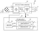
Thepower control system 100 includes a PFC andoutput voltage controller 114 to control power factor correction and regulate an output voltage VCofswitching power converter 102. The PFC andoutput voltage controller 114 controls an ON (i.e. conductive) and OFF (i.e. nonconductive) state ofswitch 108 by varying a state of pulse width modulated control signal CS0. Switching between states ofswitch 108 regulates the transfer of energy from the rectified line input voltage VXthroughinductor 110 tocapacitor 106. The inductor current iLramps ‘up’ when theswitch 108 is ON. The inductor current iLramps down whenswitch 108 is OFF and supplies current iLto rechargecapacitor 106. The time period during which inductor current iLramps down is commonly referred to as the “inductor flyback time”. During the inductor flyback time,diode 111 is forward biased.Diode 111 prevents reverse current flow intoinductor 110 whenswitch 108 is OFF. In at least one embodiment, theswitching power converter 102 operates in discontinuous current mode, i.e. the inductor current iLramp up time plus the inductor flyback time is less than the period of the control signal CS0, which controls the conductivity ofswitch 108. When operating in continuous conduction mode, the inductor current iLramp-up time plus the inductor flyback time equals the period of control signal CS0.
Inductor current iLis proportionate to the ‘on-time’ ofswitch 108, and the energy transferred toinductor 110 is proportionate to the ‘on-time’ squared. Thus, the energy transfer process is one embodiment of a nonlinear process. In at least one embodiment, control signal CS0is a pulse width modulated signal, and theswitch 108 is a field effect transistor (FET), such as an n-channel FET. Control signal CS0is a gate voltage ofswitch 108, and switch108 conducts when the pulse width of CS0is high. Thus, the ‘on-time’ ofswitch 108 is determined by the pulse width of control signal CS0. Accordingly, the energy transferred toinductor 110 is proportionate to a square of the pulse width of control signal CS0.
Capacitor106 supplies stored energy to load112. Thecapacitor 106 is sufficiently large so as to maintain a substantially constant output voltage VC, as established by PFC andoutput voltage controller 114. The output voltage VCremains substantially constant during constant load conditions. However, as load conditions change, the output voltage VCchanges. The PFC andoutput voltage controller 114 responds to the changes in VCand adjusts the control signal CS0to restore a substantially constant output voltage VCas quickly as possible. Theswitching power converter 102 includes asmall capacitor 115 to filter any high frequency signals from the input voltage VX.
The goal of power factor correction technology is to make theswitching power converter 102 appear resistive to thevoltage source 101. Thus, PFC andoutput voltage controller 114 attempts to control the inductor current iLso that the average inductor current iLis linearly and directly related to the line input voltage VX. Prodić,Compensator Design and Stability Assessment for Fast Voltage Loops of Power Factor Correction Rectifiers, IEEE Transactions on Power Electronics, Vol. 22, No. 5, Sep. 2007, pp. 1719-1729 (referred to herein as “Prodić”), describes an example of PFC andoutput voltage controller 114.
In at least one embodiment, the values of the pulse width and duty cycle of control signal CSodepend on sensing two signals, namely, the input voltage VXand the capacitor voltage/output voltage VC. PFC andoutput voltage controller 114 receives the two voltage signals, the input voltage VXand the output voltage VC, via a widebandwidth current loop 116 and aslower voltage loop 118. The input voltage VXis sensed from node120 between thediode rectifier 103 andinductor 110. The output voltage VCis sensed from node122 betweendiode 111 andload 112. Thecurrent loop 116 operates at a frequency fcthat is sufficient to allow the PFC andoutput voltage controller 114 to respond to changes in the line input voltage VXand cause the inductor current iLto track the input voltage VXto provide power factor correction. The current loop frequency is generally set to a value between 20 kHz and 130 kHz. Thevoltage loop 118 operates at a much slower frequency fv, typically 10-20 Hz. By operating at 10-20 Hz, thevoltage loop 118 functions as a low pass filter to filter an AC ripple component of the output voltage VC.
The PFC andoutput voltage controller 114 controls the pulse width (PW) and period (TT) of control signal CS0. Thus, PFC andoutput voltage controller 114 controls the nonlinear process of switchingpower converter 102 so that a desired amount of energy is transferred tocapacitor 106. The desired amount of energy depends upon the voltage and current requirements ofload 112. To regulate the amount of energy transferred and maintain a power factor close to one, PFC andoutput voltage controller 114 varies the period TT of control signal CS0so that the input current iLtracks the changes in input voltage VXand holds the output voltage VCconstant. Thus, as the input voltage VXincreases, PFC andoutput voltage controller 114 increases the period TT of control signal CS0, and as the input voltage VXdecreases, PFC andoutput voltage controller 114 decreases the period TT of control signal CS0. At the same time, the pulse width PW of control signal CS0is adjusted to maintain a constant duty cycle (D) of control signal CS0, and, thus, hold the output voltage VCconstant. In at least one embodiment, the PFC andoutput voltage controller 114 updates the control signal CS0at a frequency much greater than the frequency of input voltage VX. The frequency of input voltage VXis generally 50-60 Hz. Thefrequency 1/TT of control signal CS0is, for example, between 20 kHz and 130 kHz. Frequencies at or above 20 kHz avoid audio frequencies and frequencies at or below 130 kHz avoid significant switching inefficiencies while still maintaining good power factor, e.g. between 0.9 and 1, and an approximately constant output voltage VC.
Referring toFIG. 1 , the pulse width of control signal CS0varies over time. For example, when the power demand ofload 112 is low, such as whenload 112 is an idle or standby state, PFC andoutput voltage controller 114 controls the pulse width of control signal CS0so that some of the pulses of control signal CS0are very small. When the pulse width of control signal CS0is small,switch 108 turns ON and OFF quickly causing a short ON time duration. However, turning theswitch 108 ON for short durations can create a problem because short switching durations can be very inefficient. The inefficiency occurs because, for example, the ratio of the power required to turnswitch 108 ON to the power transferred toload 112 decreases as the ON time ofswitch 108 decreases.
In one embodiment of the present invention, an apparatus includes a delta sigma modulator having two ranges of available output values and a range of one or more unavailable intermediate output values. The range of one or more unavailable intermediate output values represent a gap in available output values and represents output values that are unavailable for use in generating a duty cycle modulated control signal to control a switch of a switching power converter. The apparatus also includes a duty cycle modulator, coupled to the delta sigma modulator, to receive the available output values from the delta sigma modulator and to generate the duty cycle modulated control signal to control the switch of the switching power converter.
In another embodiment of the present invention, a method includes generating output values with a delta sigma modulator. The output values of the delta sigma modulator include two ranges of available output values and a range of one or more unavailable intermediate output values. The range of one or more unavailable intermediate output values represents a gap in available output values and represents output values that are unavailable for use in generating a duty cycle modulated control signal to control a switch of a switching power converter. The method also includes generating the duty cycle modulated control signal to control the switch of the switching power converter using the available output values of the delta sigma modulator.
In a further embodiment of the present invention, an apparatus includes means for generating output values with a delta sigma modulator. The output values of the delta sigma modulator include two ranges of available output values and a range of one or more unavailable intermediate output values. The range of one or more unavailable intermediate output values represents a gap in available output values and represents output values that are unavailable for use in generating a duty cycle modulated control signal to control a switch of a switching power converter. The apparatus further includes means for generating the duty cycle modulated control signal to control the switch of the switching power converter using the available output values of the delta sigma modulator.
The present invention may be better understood, and its numerous objects, features and advantages made apparent to those skilled in the art by referencing the accompanying drawings. The use of the same reference number throughout the several figures designates a like or similar element.
At least one embodiment of a power control system includes a delta sigma modulator to generate output values for use in controlling a switching power converter. In at least one embodiment, the delta sigma modulator includes two ranges of available output values and a range of one or more unavailable intermediate output values, wherein the range of one or more unavailable intermediate output values represent a gap in available output values. Each unavailable intermediate output value represents an output value that is not generated by the delta sigma modulator. In at least one embodiment, the delta sigma modulator includes a quantizer output remapping module that remaps quantizer output values within the range of one or more unavailable intermediate output values of the delta sigma modulator to new output values within one of the ranges of available output values. In at least one embodiment, the unavailable output values correspond to pulse widths of the control signal to be avoided by the PFC and output voltage controller. In at least one embodiment, the PFC and output voltage controller avoids certain small control signal pulse widths that result in switching inefficiencies. In at least one embodiment, a duty cycle modulator of the PFC and output voltage controller converts the available output values of the delta sigma modulator into pulse widths of a control signal.
In at least one embodiment, the control signal represents a duty cycle modulated control signal generated by the PFC and output voltage controller. The pulse width of the control signal corresponds to available output values of the delta sigma modulator, and a pulse of the control signal causes a switch in a switching power converter to turn ON and OFF. The pulse width of the control signal determines the ON time of the switch. In at least one embodiment, the remapped delta sigma modulator output values are fed back to the delta sigma modulator, and the delta sigma modulator uses the fed back, remapped output values as the actual output value of the delta sigma modulator. In at least one embodiment, the delta sigma modulator is a conventional delta sigma modulator. In at least one embodiment, the delta sigma modulator is a nonlinear delta sigma modulator that models nonlinear processes, such as a nonlinear energy transfer process of a switching power converter.
In at least one embodiment, the avoided pulse widths of the control signal correspond to inefficient operation of the switch. For example, in at least one embodiment, a range of pulse widths correspond to low power demand by a load connected to the switching power converter. Pulse widths corresponding to low power demand are generally shorter relative to higher power operation. Short pulse widths can result in increasing switching inefficiencies because, for example, more power is used to turn the switch ON and OFF more rapidly while transferring less energy from the switching power converter.
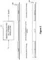
The duty cycle and periodcontrol signal generator 204 includes a restricted output delta sigma modulator207 to generate the pulse width control signal QPW(n). The restricted output delta sigma modulator207 converts input signal T1 into the pulse width control signal QPW(n). In at least one embodiment, the input signal T1 represents an initial determination of the pulse width of control signal CS1. In at least one embodiment, input signal T1 equals an initial determination of the square of the pulse width of control signal CS1. In at least one embodiment, the input signal T1 is determined as discussed in Melanson I. U.S. patent application Ser. No. 12/047,269, entitled “LIGHTING SYSTEM WITH POWER FACTOR CORRECTION CONTROL DATA DETERMINED FROM A PHASE MODULATED SIGNAL,” inventor John L. Melanson, assignee Cirrus Logic, Inc., and filing date Mar. 12, 2008 (referred to herein as “Melanson II”) also describes an exemplary determination of input signal T1. Melanson II is also hereby incorporated by reference in its entirety.
In at least one embodiment, the restricted outputdelta sigma modulator 207 restricts the possible values of the pulse width control signal QPW(n) so that control signal CS1avoids certain pulse widths. In at least one embodiment, the control signal represents a duty cycle modulated control signal generated by the PFC andoutput voltage controller 202. The pulse width of the control signal CS1corresponds to output values of the restricted outputdelta sigma modulator 207, and a pulse of the control signal CS1causes switch211 in switchingpower converter 206 to turn ON and OFF. Switch211 can be any type of switch. In at least one embodiment,switch 211 is the same type of switch asswitch 108, such as an n-channel field effect transistor.
The pulse width of the control signal CS1determines the ON time of theswitch 211. In at least one embodiment, the avoided pulse widths of the control signal CS1correspond to inefficient operation of theswitch 211. For example, in at least one embodiment, a range of pulse widths correspond to low power demand by aload 112 connected to the switchingpower converter 206. Pulse widths of control signal CS1corresponding to low power demand byload 112 are generally shorter relative to higher power operation. Short pulse widths can result in increasing switching inefficiencies because, for example, more power is used to turn theswitch 211 ON and OFF more rapidly while transferring less energy from the switching power converter restricted output delta sigma modulator207 to load112.Load 112 can be any type of load including one or more light emitting diode based lighting fixtures.
To improve efficiency, in at least one embodiment, the restricted output delta sigma modulator207 remaps all quantizer output values that are within an unavailable output range to output values in an available range. By remapping the quantizer output values, the duty cycle and periodcontrol signal generator 204 avoids pulse widths corresponding to the quantizer output values in the unavailable output value range.
Referring toFIGS. 2 and 3 , values of pulse width control signal QPW(n) directly correspond to the pulse width of control signal CS1. In at least one embodiment, the quantizer output values of restricted output delta sigma modulator207 are identified by discrete identifiers, and “0” indicates a quantizer output value corresponding to a pulse width of zero duration, a quantizer output value of “1” indicates the next smallest pulse width, and so on. If the output values304 of restricted output delta sigma modulator300 have an AVAILABLE OUTPUT RANGE0of {0}, AVAILABLE OUTPUT RANGE1of {5, 6, 7, . . . N}, and an UNAVAILABLE INTERMEDIATE OUTPUT RANGE0of {1, 2, 3, 4}, then the restricted outputdelta sigma modulator 207 avoids values of pulse width control signal QPW(n) in the range {1, 2, 3, 4}. “N” represents the last available output value in AVAILABLE OUTPUT RANGE1. In at least one embodiment, restricted output delta sigma modulator207 remaps output values in the UNAVAILABLE INTERMEDIATE OUTPUT RANGE0to output values in either AVAILABLE OUTPUT RANGE0or AVAILABLE OUTPUT RANGE1so that the control signal CS1will have a pulse width of 0 or a pulse width of 6. The pulse widths corresponding tooutput values 304 in the UNAVAILABLE INTERMEDIATE OUTPUT RANGE0represent short ON times ofswitch 211, with “1” being the smallest and “5” being the longest. By remapping the UNAVAILABLE INTERMEDIATE OUTPUT RANGE0ofoutput values 304 to either AVAILABLE OUTPUT RANGE0or AVAILABLE OUTPUT RANGE1, the short ON times ofswitch 211 associated with the UNAVAILABLE INTERMEDIATE OUTPUT RANGE0are eliminated. Thus, the efficiency ofswitch 211 is improved.
In at least one embodiment, the restricted outputdelta sigma modulator 207 ensures that the average pulse width of control signal CS1matches the average pulse width indicated by input signal T1. By maintaining the average pulse width of control signal CS1as indicated by input signal T1, remapping the unavailable range of output values does not affect the average power output of switchingpower converter 206.
The switchingpower converter 206 can be any type of switching power converter such as a boost, buck, or boost-buck type switching power converter. In at least one embodiment, the switchingpower converter 206 includes a powerfactor correction stage 208 and adriver stage 210. The configuration of the powerfactor correction stage 208 and thedriver stage 210 is a matter of design choice and depends upon the switching power converter type. In at least one embodiment, switchingpower converter 206 is configured identically to switchingpower converter 102 ofFIG. 1 .
The output remapping-delta-sigma modulator 400 also includes aremapping module 404. Theremapping module 404 remaps at least a subset of the values of the quantizer output q(n) to new values. In at least one embodiment, theremapping module 404 determines if the quantizer output q(n) has a value in an unavailable set of values, i.e. the subset of values to be remapped. If the quantizer output q(n) has a first value that is included in the unavailable set, then theremapping module 404 maps the first value to a second value. In at least one embodiment, if the quantizer output q(n) has a value that is not in the unavailable set, then theremapping module 404 does not remap the quantizer output q(n), and the pulse width control signal QPW(n) equals the quantizer output q(n). The values in the unavailable set are a matter of design choice. The values in the unavailable set can be consecutive values, nonconsecutive values, or any set or sets of values. The value or values to which the quantizer output q(n) is remapped (referred to as the “remapped values”) are a matter of design choice. In at least one embodiment, the unavailable set of quantizer output q(n) values correspond to pulse widths of control signal CS1to be avoided, and the remapped values correspond to zero duration pulse width and a pulse width having a duration greater than the longest avoided pulse width.
The output remapping-delta-sigma modulator 400 feeds back the pulse width control signal QPW(n) as if the pulse width control signal QPW(n) was the actual quantizer output q(n). Thedelay z −1406 indicates that the previous value of pulse width control signal QPW(n), i.e. pulse width control signal QPW(n−1), represents the quantizer feedback for delta sigma modulatorforward path 402. By feeding back the pulse width control signal QPW(n−1), the average value of pulse width control signal QPW(n) equals the average value of input signal T1. Thus, the average power output of switchingpower converter 206 is unaffected by output remapping-delta-sigma modulator 400.
Theremapping module 502 feeds the quantizer output q(n) intomultiplexer 504 and intovalue identifiers value identifier 506 determines that quantizer output q(n) is a member of the unavailable set {LOW}, thenvalue identifier 506 sends a select signal S0to a select node S ofmultiplexer 504 that causes the multiplexer output M0to equal low remapped value rL. Ifvalue identifier 506 determines that quantizer output q(n) is not a member of the unavailable set {LOW}, thenvalue identifier 506 sends a select signal S0to select node S ofmultiplexer 504 that causes the multiplexer output M0to equal the quantizer output q(n). The multiplexer output M0is fed into an input ofmultiplexer 510. Ifvalue identifier 508 determines that quantizer output q(n) is a member of the unavailable set {HIGH}, thenvalue identifier 508 sends a select signal S0to a select node S ofmultiplexer 510 that causes pulse width control signal QPW(n) to equal low remapped value rL. Ifvalue identifier 508 determines that quantizer output q(n) is not a member of the unavailable set {HIGH}, thenvalue identifier 508 sends a select signal S0to select node S ofmultiplexer 510 that causes pulse width control signal QPW(n) to equal the multiplexer output M0.
The particular values of the unavailable set {LOW, HIGH}, low remapped value rL, and high remapped value rHare a matter of design choice. For the set {LOW} equal {1,3,4}, {HIGH} equal {2}, low remapped value rLequal 0, and high remapped value rHequal 1, Table 1 below depicts exemplary values for quantizer output q(n) and pulse width control signal QPW(n):
| TABLE 1 | |||
| q(n) | QPW(n) | ||
| 1 | 0 | ||
| 2 | 5 | ||
| 3 | 0 | ||
| 4 | 0 | ||
So, the pulse width control signal QPW(n) will always be a 0 or a 5. Avoiding pulse widths of 1, 2, 3, and 4 creates a dead zone so that the pulse width of control signal CS0will either be zero or correspond to a quantizer output value of 5 or more. The dead zone prevents inefficient switching frequencies ofswitch 211.
In at least one embodiment, the quantizer output q(n) varies by +/−1 or +/−2. Thus, the quantizer output q(n) varies very little from output to output. If the previous value of quantizer output q(n) is 5, then the next value can only be as low as 3. If the previous value of pulse width control signal QPW(n−1)=5, then the next value of pulse width control signal QPW(n) should be 3, 4, 6, or 7. If the previous value of pulse width control signal QPW(n−1)=0, then the next value of pulse width control signal QPW(n) should be 1 or 2. Table 2 depicts the current quantizer output q(n), the normal output N, and the remapped output=pulse width control signal QPW(n):
| TABLE 2 | ||
| QPW(n − 1) | N | QPW(n) |
| 5 | 4 | 0 |
| 5 | 3 | 0 |
| 5 | 6 or 7 | 6 or 7 |
| 0 | 1 | 0 |
| 0 | 2 | 5 |
In accordance with Table 2, although the pulse width control signal QPW(n) varies between 0, 5, 6, and 7 when the quantizer output q(n) values in the unavailable set are remapped to 0 and 5, the average value of pulse width control signal QPW(n) matches the normal value N over time. Since the average pulse width control signal QPW(n) matches the normal value, the average power of switchingpower converter 206 is unaffected by remapping. The particular remapping scheme is a matter of design choice.
Table 3 below depicts exemplary values for quantizer output q(n) and pulse width control signal QPW(n) for nonlinear output remapping-delta-sigma modulator 600 for an unavailable range of output values of {1, 2, 3, 4}:
| TABLE 3 | |||
| q(n) | QPW(n) | ||
| 1 | 0 | ||
| 2 | 0 | ||
| 3 | 5 | ||
| 4 | 5 | ||
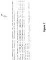
The output remapping-delta-sigma modulator 400 can be implemented in hardware, software, or a combination of hardware and software.FIG. 7 depictsexemplary C++ code 700 to implement output remapping-delta-sigma modulator 600. Thecode 700 can be stored in a memory and executed by a processor (not shown).
Thus, a power control system includes a delta sigma modulator having two ranges of available output values and a range of one or more unavailable intermediate output values. The range of one or more unavailable intermediate output values represents a gap in available output values. The power control system also includes a duty cycle modulator to receive the available output values from the delta sigma modulator and to generate a duty cycle modulated control signal to control a switch of a switching power converter.
Although the present invention has been described in detail, it should be understood that various changes, substitutions and alterations can be made hereto without departing from the spirit and scope of the invention as defined by the appended claims.
Claims (25)
1. An apparatus comprising:
a delta sigma modulator having two ranges of available output values and a range of one or more unavailable intermediate output values, wherein the range of one or more unavailable intermediate output values represent a gap in available output values and represents output values that are unavailable for use in generating a duty cycle modulated control signal to control a switch of a switching power converter; and
a duty cycle modulator, coupled to the delta sigma modulator, to receive the available output values from the delta sigma modulator and to generate the duty cycle modulated control signal to control the switch of the switching power converter.
2. The apparatus ofclaim 1 wherein the delta sigma modulator comprises:
a quantizer to generate quantizer output values; and
a remapping module to receive the quantizer output values and to remap quantizer output values having values in the range of unavailable intermediate output values to output values in at least one of the available output value ranges.
3. The apparatus ofclaim 2 wherein the delta sigma modulator includes a quantizer and the remapping module is further configured to provide remapped quantizer output values as quantizer feedback values.
4. The apparatus ofclaim 1 wherein each of the one or more unavailable intermediate output values is greater than each available output value in a first of the two ranges of available output values and each of the one or more unavailable intermediate output values is less than each available output value in a second of the two ranges of available output values.
5. The apparatus ofclaim 1 wherein the range of unavailable intermediate output values corresponds to a zero power zone for the switching power converter.
6. The apparatus ofclaim 5 wherein the zero power zone is a zone ranging from zero power to a power level that is less than fifty percent of a maximum output power of the switching power converter.
7. The apparatus ofclaim 1 wherein the delta sigma modulator includes multiple ranges of unavailable intermediate output values.
8. The apparatus ofclaim 1 wherein the range of unavailable intermediate output values correspond to a range of power output levels of the switching power converter.
9. The apparatus ofclaim 8 wherein the range of power output levels is from approximately zero power to less than or equal to approximately ten percent of maximum output power of the switching power converter.
10. The apparatus ofclaim 1 wherein the switching power converter is selected from a group consisting of a boost converter, a buck converter, and a boost/buck converter.
11. The apparatus ofclaim 1 wherein the delta sigma modulator is a nonlinear delta sigma modulator.
12. The apparatus ofclaim 1 wherein one of the ranges of available output values consists of a single output value, and the single output value is less than each of the one or more unavailable intermediate output values.
13. A method comprising:
generating output values with a delta sigma modulator, wherein (i) the output values of the delta sigma modulator include two ranges of available output values and a range of one or more unavailable intermediate output values and (ii) the range of one or more unavailable intermediate output values represents a gap in available output values and represents output values that are unavailable for use in generating a duty cycle modulated control signal to control a switch of a switching power converter; and
generating the duty cycle modulated control signal to control the switch of the switching power converter using the available output values of the delta sigma modulator.
14. The method ofclaim 13 wherein generating output values with a delta sigma modulator further comprises:
generating quantizer output values;
receiving the quantizer output values;
remapping quantizer output values having values in the range of unavailable intermediate output values to output values in at least one of the available output value ranges.
15. The method ofclaim 14 further comprising:
providing remapped quantizer output values as quantizer feedback values to the delta sigma modulator.
16. The method ofclaim 13 wherein each of the one or more unavailable intermediate output values is greater than each available output value in a first of the two ranges of available output values and each of the one or more unavailable intermediate output values is less than each available output value in a second of the two ranges of available output values.
17. The method ofclaim 13 wherein the range of unavailable intermediate output values corresponds to a zero power zone for the switching power converter.
18. The method ofclaim 17 wherein the zero power zone is a zone ranging from zero power to a power level that is less than fifty percent of a maximum output power of the switching power converter.
19. The method ofclaim 13 wherein the delta sigma modulator includes multiple ranges of unavailable intermediate output values.
20. The method ofclaim 13 wherein the range of unavailable intermediate output values correspond to a range of power output levels of the switching power converter.
21. The method ofclaim 20 wherein the range of power output levels is from approximately zero power to less than or equal to approximately ten percent of maximum output power of the switching power converter.
22. The method ofclaim 13 wherein the switching power converter is selected from a group consisting of a boost converter, buck converter, and boost/buck converter.
23. The method ofclaim 13 wherein the delta sigma modulator is a nonlinear delta sigma modulator.
24. The method ofclaim 13 wherein one of the ranges of available output values consists of a single output value, and the single output value is less than each of the one or more unavailable intermediate output values.
25. An apparatus comprising:
means for generating output values with a delta sigma modulator, wherein the output values of the delta sigma modulator include two ranges of available output values and a range of one or more unavailable intermediate output values, wherein the range of one or more unavailable intermediate output values represents a gap in available output values and represents output values that are unavailable for use in generating a duty cycle modulated control signal to control a switch of a switching power converter; and
means for generating the duty cycle modulated control signal to control the switch of the switching power converter using the available output values of the delta sigma modulator.
Priority Applications (2)
| Application Number | Priority Date | Filing Date | Title |
|---|---|---|---|
| US12/241,940US7755525B2 (en) | 2008-01-30 | 2008-09-30 | Delta sigma modulator with unavailable output values |
| PCT/US2009/032351WO2009099865A1 (en) | 2008-01-30 | 2009-01-29 | Delta sigma modulator with unavailable output values |
Applications Claiming Priority (2)
| Application Number | Priority Date | Filing Date | Title |
|---|---|---|---|
| US2458208P | 2008-01-30 | 2008-01-30 | |
| US12/241,940US7755525B2 (en) | 2008-01-30 | 2008-09-30 | Delta sigma modulator with unavailable output values |
Publications (2)
| Publication Number | Publication Date |
|---|---|
| US20090191837A1 US20090191837A1 (en) | 2009-07-30 |
| US7755525B2true US7755525B2 (en) | 2010-07-13 |
Family
ID=40899741
Family Applications (1)
| Application Number | Title | Priority Date | Filing Date |
|---|---|---|---|
| US12/241,940Expired - Fee RelatedUS7755525B2 (en) | 2008-01-30 | 2008-09-30 | Delta sigma modulator with unavailable output values |
Country Status (2)
| Country | Link |
|---|---|
| US (1) | US7755525B2 (en) |
| WO (1) | WO2009099865A1 (en) |
Cited By (7)
| Publication number | Priority date | Publication date | Assignee | Title |
|---|---|---|---|---|
| US8552893B1 (en)* | 2010-11-04 | 2013-10-08 | Cirrus Logic, Inc. | Control system using nonlinear delta-sigma modulator with switching period error compensation |
| US8643300B1 (en)* | 2011-07-21 | 2014-02-04 | Dale B. Stepps | Power control system and method for providing an optimal power level to a designated light fixture |
| US20150171888A1 (en)* | 2013-12-06 | 2015-06-18 | Nxp B.V. | Sigma-delta modulator |
| US9155139B2 (en) | 2012-03-09 | 2015-10-06 | Rockwell Automation Technologies, Inc. | LED driver circuits and methods |
| US9313840B2 (en) | 2011-06-03 | 2016-04-12 | Cirrus Logic, Inc. | Control data determination from primary-side sensing of a secondary-side voltage in a switching power converter |
| US9510401B1 (en) | 2010-08-24 | 2016-11-29 | Cirrus Logic, Inc. | Reduced standby power in an electronic power control system |
| US20230216405A1 (en)* | 2021-12-30 | 2023-07-06 | Stmicroelectronics S.R.L. | Control loop and efficiency enhancement for dc-dc converters |
Families Citing this family (8)
| Publication number | Priority date | Publication date | Assignee | Title |
|---|---|---|---|---|
| US7804697B2 (en)* | 2007-12-11 | 2010-09-28 | Cirrus Logic, Inc. | History-independent noise-immune modulated transformer-coupled gate control signaling method and apparatus |
| US8008898B2 (en) | 2008-01-30 | 2011-08-30 | Cirrus Logic, Inc. | Switching regulator with boosted auxiliary winding supply |
| US8008902B2 (en) | 2008-06-25 | 2011-08-30 | Cirrus Logic, Inc. | Hysteretic buck converter having dynamic thresholds |
| US8847719B2 (en) | 2008-07-25 | 2014-09-30 | Cirrus Logic, Inc. | Transformer with split primary winding |
| US8222872B1 (en) | 2008-09-30 | 2012-07-17 | Cirrus Logic, Inc. | Switching power converter with selectable mode auxiliary power supply |
| US8212493B2 (en) | 2009-06-30 | 2012-07-03 | Cirrus Logic, Inc. | Low energy transfer mode for auxiliary power supply operation in a cascaded switching power converter |
| US8198874B2 (en)* | 2009-06-30 | 2012-06-12 | Cirrus Logic, Inc. | Switching power converter with current sensing transformer auxiliary power supply |
| CN102255490A (en)* | 2011-04-29 | 2011-11-23 | 佛山市南海赛威科技技术有限公司 | PFC (power factor correction) circuit based on delta-sigma modulation technique and duty ratio control method thereof |
Citations (131)
| Publication number | Priority date | Publication date | Assignee | Title |
|---|---|---|---|---|
| US3790878A (en) | 1971-12-22 | 1974-02-05 | Keithley Instruments | Switching regulator having improved control circuiting |
| US3881167A (en) | 1973-07-05 | 1975-04-29 | Pelton Company Inc | Method and apparatus to maintain constant phase between reference and output signals |
| US4075701A (en) | 1975-02-12 | 1978-02-21 | Messerschmitt-Bolkow-Blohm Gesellschaft Mit Beschrankter Haftung | Method and circuit arrangement for adapting the measuring range of a measuring device operating with delta modulation in a navigation system |
| US4334250A (en) | 1978-03-16 | 1982-06-08 | Tektronix, Inc. | MFM data encoder with write precompensation |
| US4414493A (en) | 1981-10-06 | 1983-11-08 | Thomas Industries Inc. | Light dimmer for solid state ballast |
| US4476706A (en) | 1982-01-18 | 1984-10-16 | Delphian Partners | Remote calibration system |
| US4677366A (en) | 1986-05-12 | 1987-06-30 | Pioneer Research, Inc. | Unity power factor power supply |
| US4683529A (en) | 1986-11-12 | 1987-07-28 | Zytec Corporation | Switching power supply with automatic power factor correction |
| US4700188A (en) | 1985-01-29 | 1987-10-13 | Micronic Interface Technologies | Electric power measurement system and hall effect based electric power meter for use therein |
| US4797633A (en) | 1987-03-20 | 1989-01-10 | Video Sound, Inc. | Audio amplifier |
| US4940929A (en) | 1989-06-23 | 1990-07-10 | Apollo Computer, Inc. | AC to DC converter with unity power factor |
| US4973919A (en) | 1989-03-23 | 1990-11-27 | Doble Engineering Company | Amplifying with directly coupled, cascaded amplifiers |
| US4979087A (en) | 1988-09-09 | 1990-12-18 | Aviation Limited | Inductive coupler |
| US4992919A (en) | 1989-12-29 | 1991-02-12 | Lee Chu Quon | Parallel resonant converter with zero voltage switching |
| US4994952A (en) | 1988-02-10 | 1991-02-19 | Electronics Research Group, Inc. | Low-noise switching power supply having variable reluctance transformer |
| US5206540A (en) | 1991-05-09 | 1993-04-27 | Unitrode Corporation | Transformer isolated drive circuit |
| US5278490A (en) | 1990-09-04 | 1994-01-11 | California Institute Of Technology | One-cycle controlled switching circuit |
| EP0585789A1 (en) | 1992-09-01 | 1994-03-09 | Power Integrations, Inc. | Three-terminal switched mode power supply integrated circuit |
| US5323157A (en) | 1993-01-15 | 1994-06-21 | Motorola, Inc. | Sigma-delta digital-to-analog converter with reduced noise |
| US5359180A (en) | 1992-10-02 | 1994-10-25 | General Electric Company | Power supply system for arcjet thrusters |
| US5383109A (en) | 1993-12-10 | 1995-01-17 | University Of Colorado | High power factor boost rectifier apparatus |
| US5477481A (en) | 1991-02-15 | 1995-12-19 | Crystal Semiconductor Corporation | Switched-capacitor integrator with chopper stabilization performed at the sampling rate |
| US5481178A (en) | 1993-03-23 | 1996-01-02 | Linear Technology Corporation | Control circuit and method for maintaining high efficiency over broad current ranges in a switching regulator circuit |
| US5565761A (en) | 1994-09-02 | 1996-10-15 | Micro Linear Corp | Synchronous switching cascade connected offline PFC-PWM combination power converter controller |
| US5638265A (en) | 1993-08-24 | 1997-06-10 | Gabor; George | Low line harmonic AC to DC power supply |
| US5691890A (en) | 1995-12-01 | 1997-11-25 | International Business Machines Corporation | Power supply with power factor correction circuit |
| US5747977A (en) | 1995-03-30 | 1998-05-05 | Micro Linear Corporation | Switching regulator having low power mode responsive to load power consumption |
| US5781040A (en) | 1996-10-31 | 1998-07-14 | Hewlett-Packard Company | Transformer isolated driver for power transistor using frequency switching as the control signal |
| US5783909A (en) | 1997-01-10 | 1998-07-21 | Relume Corporation | Maintaining LED luminous intensity |
| US5900683A (en) | 1997-12-23 | 1999-05-04 | Ford Global Technologies, Inc. | Isolated gate driver for power switching device and method for carrying out same |
| US5929400A (en) | 1997-12-22 | 1999-07-27 | Otis Elevator Company | Self commissioning controller for field-oriented elevator motor/drive system |
| US5946202A (en) | 1997-01-24 | 1999-08-31 | Baker Hughes Incorporated | Boost mode power conversion |
| US5952849A (en) | 1997-02-21 | 1999-09-14 | Analog Devices, Inc. | Logic isolator with high transient immunity |
| US5963086A (en) | 1997-08-08 | 1999-10-05 | Velodyne Acoustics, Inc. | Class D amplifier with switching control |
| US5966297A (en) | 1997-08-28 | 1999-10-12 | Iwatsu Electric Co., Ltd. | Large bandwidth analog isolation circuit |
| US6016038A (en) | 1997-08-26 | 2000-01-18 | Color Kinetics, Inc. | Multicolored LED lighting method and apparatus |
| US6043633A (en) | 1998-06-05 | 2000-03-28 | Systel Development & Industries | Power factor correction method and apparatus |
| US6072969A (en) | 1996-03-05 | 2000-06-06 | Canon Kabushiki Kaisha | Developing cartridge |
| US6083276A (en) | 1998-06-11 | 2000-07-04 | Corel, Inc. | Creating and configuring component-based applications using a text-based descriptive attribute grammar |
| US6084450A (en) | 1997-01-14 | 2000-07-04 | The Regents Of The University Of California | PWM controller with one cycle response |
| US6211626B1 (en) | 1997-08-26 | 2001-04-03 | Color Kinetics, Incorporated | Illumination components |
| US6211627B1 (en) | 1997-07-29 | 2001-04-03 | Michael Callahan | Lighting systems |
| US6229271B1 (en) | 2000-02-24 | 2001-05-08 | Osram Sylvania Inc. | Low distortion line dimmer and dimming ballast |
| US6246183B1 (en) | 2000-02-28 | 2001-06-12 | Litton Systems, Inc. | Dimmable electrodeless light source |
| US6259614B1 (en) | 1999-07-12 | 2001-07-10 | International Rectifier Corporation | Power factor correction control circuit |
| US6304473B1 (en) | 2000-06-02 | 2001-10-16 | Iwatt | Operating a power converter at optimal efficiency |
| US6344811B1 (en) | 1999-03-16 | 2002-02-05 | Audio Logic, Inc. | Power supply compensation for noise shaped, digital amplifiers |
| US6385063B1 (en) | 1998-06-23 | 2002-05-07 | Siemens Aktiengesellschaft | Hybrid filter for an alternating current network |
| EP1213823A2 (en) | 2000-12-04 | 2002-06-12 | Sanken Electric Co., Ltd. | DC-to-DC converter |
| US6407691B1 (en) | 2000-10-18 | 2002-06-18 | Cirrus Logic, Inc. | Providing power, clock, and control signals as a single combined signal across an isolation barrier in an ADC |
| US6445600B2 (en) | 1998-07-13 | 2002-09-03 | Ben-Gurion University Of The Negev Research & Development Authority | Modular structure of an apparatus for regulating the harmonics of current drawn from power lines by an electronic load |
| US20020145041A1 (en) | 2001-03-16 | 2002-10-10 | Koninklijke Philips Electronics N.V. | RGB LED based light driver using microprocessor controlled AC distributed power system |
| US20020150151A1 (en) | 1997-04-22 | 2002-10-17 | Silicon Laboratories Inc. | Digital isolation system with hybrid circuit in ADC calibration loop |
| US20020166073A1 (en) | 2001-05-02 | 2002-11-07 | Nguyen James Hung | Apparatus and method for adaptively controlling power supplied to a hot-pluggable subsystem |
| WO2002091805A2 (en) | 2001-05-10 | 2002-11-14 | Color Kinetics Incorporated | Systems and methods for synchronizing lighting effects |
| US6509913B2 (en) | 1998-04-30 | 2003-01-21 | Openwave Systems Inc. | Configurable man-machine interface |
| US6583550B2 (en) | 2000-10-24 | 2003-06-24 | Toyoda Gosei Co., Ltd. | Fluorescent tube with light emitting diodes |
| US6636003B2 (en) | 2000-09-06 | 2003-10-21 | Spectrum Kinetics | Apparatus and method for adjusting the color temperature of white semiconduct or light emitters |
| US20030223255A1 (en) | 2002-05-31 | 2003-12-04 | Green Power Technologies Ltd. | Method and apparatus for active power factor correction with minimum input current distortion |
| US20040046683A1 (en) | 2001-03-08 | 2004-03-11 | Shindengen Electric Manufacturing Co., Ltd. | DC stabilized power supply |
| US6713974B2 (en) | 2002-01-10 | 2004-03-30 | Lightech Electronic Industries Ltd. | Lamp transformer for use with an electronic dimmer and method for use thereof for reducing acoustic noise |
| US6727832B1 (en)* | 2002-11-27 | 2004-04-27 | Cirrus Logic, Inc. | Data converters with digitally filtered pulse width modulation output stages and methods and systems using the same |
| US20040085030A1 (en) | 2002-10-30 | 2004-05-06 | Benoit Laflamme | Multicolor lamp system |
| US20040085117A1 (en) | 2000-12-06 | 2004-05-06 | Joachim Melbert | Method and device for switching on and off power semiconductors, especially for the torque-variable operation of an asynchronous machine, for operating an ignition system for spark ignition engines, and switched-mode power supply |
| US6741123B1 (en) | 2002-12-26 | 2004-05-25 | Cirrus Logic, Inc. | Delta-sigma amplifiers with output stage supply voltage variation compensation and methods and digital amplifier systems using the same |
| US6768655B1 (en) | 2003-02-03 | 2004-07-27 | System General Corp. | Discontinuous mode PFC controller having a power saving modulator and operation method thereof |
| US6781351B2 (en) | 2002-08-17 | 2004-08-24 | Supertex Inc. | AC/DC cascaded power converters having high DC conversion ratio and improved AC line harmonics |
| US20040169477A1 (en) | 2003-02-28 | 2004-09-02 | Naoki Yanai | Dimming-control lighting apparatus for incandescent electric lamp |
| US6788011B2 (en) | 1997-08-26 | 2004-09-07 | Color Kinetics, Incorporated | Multicolored LED lighting method and apparatus |
| US20040227571A1 (en) | 2003-05-12 | 2004-11-18 | Yasuji Kuribayashi | Power amplifier circuit |
| US20040228116A1 (en) | 2003-05-13 | 2004-11-18 | Carroll Miller | Electroluminescent illumination for a magnetic compass |
| US20040232971A1 (en) | 2003-03-06 | 2004-11-25 | Denso Corporation | Electrically insulated switching element drive circuit |
| US20040239262A1 (en) | 2002-05-28 | 2004-12-02 | Shigeru Ido | Electronic ballast for a discharge lamp |
| US6839247B1 (en) | 2003-07-10 | 2005-01-04 | System General Corp. | PFC-PWM controller having a power saving means |
| US6860628B2 (en) | 2002-07-17 | 2005-03-01 | Jonas J. Robertson | LED replacement for fluorescent lighting |
| US20050057237A1 (en) | 2002-01-11 | 2005-03-17 | Robert Clavel | Power factor controller |
| US6870325B2 (en) | 2002-02-22 | 2005-03-22 | Oxley Developments Company Limited | Led drive circuit and method |
| US6873065B2 (en) | 1997-10-23 | 2005-03-29 | Analog Devices, Inc. | Non-optical signal isolator |
| US6882552B2 (en) | 2000-06-02 | 2005-04-19 | Iwatt, Inc. | Power converter driven by power pulse and sense pulse |
| US6888322B2 (en) | 1997-08-26 | 2005-05-03 | Color Kinetics Incorporated | Systems and methods for color changing device and enclosure |
| US6894471B2 (en) | 2002-05-31 | 2005-05-17 | St Microelectronics S.R.L. | Method of regulating the supply voltage of a load and related voltage regulator |
| US20050156770A1 (en) | 2004-01-16 | 2005-07-21 | Melanson John L. | Jointly nonlinear delta sigma modulators |
| US6933706B2 (en) | 2003-09-15 | 2005-08-23 | Semiconductor Components Industries, Llc | Method and circuit for optimizing power efficiency in a DC-DC converter |
| US20050184895A1 (en) | 2004-02-25 | 2005-08-25 | Nellcor Puritan Bennett Inc. | Multi-bit ADC with sigma-delta modulation |
| US6940733B2 (en) | 2002-08-22 | 2005-09-06 | Supertex, Inc. | Optimal control of wide conversion ratio switching converters |
| US6944034B1 (en) | 2003-06-30 | 2005-09-13 | Iwatt Inc. | System and method for input current shaping in a power converter |
| US20050218838A1 (en) | 2004-03-15 | 2005-10-06 | Color Kinetics Incorporated | LED-based lighting network power control methods and apparatus |
| US6956750B1 (en) | 2003-05-16 | 2005-10-18 | Iwatt Inc. | Power converter controller having event generator for detection of events and generation of digital error |
| US6958920B2 (en) | 2003-10-02 | 2005-10-25 | Supertex, Inc. | Switching power converter and method of controlling output voltage thereof using predictive sensing of magnetic flux |
| US20050253533A1 (en) | 2002-05-09 | 2005-11-17 | Color Kinetics Incorporated | Dimmable LED-based MR16 lighting apparatus methods |
| US6967448B2 (en) | 1997-08-26 | 2005-11-22 | Color Kinetics, Incorporated | Methods and apparatus for controlling illumination |
| US6970503B1 (en) | 2000-04-21 | 2005-11-29 | National Semiconductor Corporation | Apparatus and method for converting analog signal to pulse-width-modulated signal |
| US6975079B2 (en) | 1997-08-26 | 2005-12-13 | Color Kinetics Incorporated | Systems and methods for controlling illumination sources |
| US20050275354A1 (en) | 2004-06-10 | 2005-12-15 | Hausman Donald F Jr | Apparatus and methods for regulating delivery of electrical energy |
| US20060023002A1 (en) | 2004-08-02 | 2006-02-02 | Oki Electric Industry Co., Ltd. | Color balancing circuit for a display panel |
| US20060022916A1 (en) | 2004-06-14 | 2006-02-02 | Natale Aiello | LED driving device with variable light intensity |
| EP1014563B1 (en) | 1998-12-14 | 2006-03-01 | Alcatel | Amplifier arrangement with voltage gain and reduced power consumption |
| US20060125420A1 (en) | 2004-12-06 | 2006-06-15 | Michael Boone | Candle emulation device |
| US7064498B2 (en) | 1997-08-26 | 2006-06-20 | Color Kinetics Incorporated | Light-emitting diode based products |
| US7075329B2 (en) | 2003-04-30 | 2006-07-11 | Analog Devices, Inc. | Signal isolators using micro-transformers |
| US7078963B1 (en) | 2003-03-21 | 2006-07-18 | D2Audio Corporation | Integrated PULSHI mode with shutdown |
| US7088059B2 (en) | 2004-07-21 | 2006-08-08 | Boca Flasher | Modulated control circuit and method for current-limited dimming and color mixing of display and illumination systems |
| US7102902B1 (en) | 2005-02-17 | 2006-09-05 | Ledtronics, Inc. | Dimmer circuit for LED |
| US7106603B1 (en) | 2005-05-23 | 2006-09-12 | Li Shin International Enterprise Corporation | Switch-mode self-coupling auxiliary power device |
| US7109791B1 (en) | 2004-07-09 | 2006-09-19 | Rf Micro Devices, Inc. | Tailored collector voltage to minimize variation in AM to PM distortion in a power amplifier |
| US20060226795A1 (en) | 2005-04-08 | 2006-10-12 | S.C. Johnson & Son, Inc. | Lighting device having a circuit including a plurality of light emitting diodes, and methods of controlling and calibrating lighting devices |
| US20060261754A1 (en) | 2005-05-18 | 2006-11-23 | Samsung Electro-Mechanics Co., Ltd. | LED driving circuit having dimming circuit |
| US7145295B1 (en) | 2005-07-24 | 2006-12-05 | Aimtron Technology Corp. | Dimming control circuit for light-emitting diodes |
| WO2006135584A1 (en) | 2005-06-10 | 2006-12-21 | Rf Micro Devices, Inc. | Doherty amplifier configuration for a collector controlled power amplifier |
| US7158633B1 (en) | 1999-11-16 | 2007-01-02 | Silicon Laboratories, Inc. | Method and apparatus for monitoring subscriber loop interface circuitry power dissipation |
| US20070029946A1 (en) | 2005-08-03 | 2007-02-08 | Yu Chung-Che | APPARATUS OF LIGHT SOURCE AND ADJUSTABLE CONTROL CIRCUIT FOR LEDs |
| US20070040512A1 (en) | 2005-08-17 | 2007-02-22 | Tir Systems Ltd. | Digitally controlled luminaire system |
| US7183957B1 (en) | 2005-12-30 | 2007-02-27 | Cirrus Logic, Inc. | Signal processing system with analog-to-digital converter using delta-sigma modulation having an internal stabilizer loop |
| US20070053182A1 (en) | 2005-09-07 | 2007-03-08 | Jonas Robertson | Combination fluorescent and LED lighting system |
| US20070103949A1 (en) | 2004-08-27 | 2007-05-10 | Sanken Electric Co., Ltd. | Power factor improving circuit |
| US7221130B2 (en) | 2005-01-05 | 2007-05-22 | Fyrestorm, Inc. | Switching power converter employing pulse frequency modulation control |
| US7233135B2 (en) | 2003-09-29 | 2007-06-19 | Murata Manufacturing Co., Ltd. | Ripple converter |
| US20070182699A1 (en) | 2006-02-09 | 2007-08-09 | Samsung Electro-Mechanics Co., Ltd. | Field sequential color mode liquid crystal display |
| US7255457B2 (en) | 1999-11-18 | 2007-08-14 | Color Kinetics Incorporated | Methods and apparatus for generating and modulating illumination conditions |
| US7266001B1 (en) | 2004-03-19 | 2007-09-04 | Marvell International Ltd. | Method and apparatus for controlling power factor correction |
| US7288902B1 (en) | 2007-03-12 | 2007-10-30 | Cirrus Logic, Inc. | Color variations in a dimmable lighting device with stable color temperature light sources |
| US7292013B1 (en) | 2004-09-24 | 2007-11-06 | Marvell International Ltd. | Circuits, systems, methods, and software for power factor correction and/or control |
| US7310244B2 (en) | 2006-01-25 | 2007-12-18 | System General Corp. | Primary side controlled switching regulator |
| US20080174372A1 (en) | 2007-01-19 | 2008-07-24 | Tucker John C | Multi-stage amplifier with multiple sets of fixed and variable voltage rails |
| US20080192509A1 (en) | 2007-02-13 | 2008-08-14 | Dhuyvetter Timothy A | Dc-dc converter with isolation |
| US20080224635A1 (en) | 2004-12-20 | 2008-09-18 | Outside In (Cambridge) Limited | Lighting Apparatus and Method |
| US20080259655A1 (en) | 2007-04-19 | 2008-10-23 | Da-Chun Wei | Switching-mode power converter and pulse-width-modulation control circuit with primary-side feedback control |
| US20080278132A1 (en) | 2007-05-07 | 2008-11-13 | Kesterson John W | Digital Compensation For Cable Drop In A Primary Side Control Power Supply Controller |
| US7545130B2 (en) | 2005-11-11 | 2009-06-09 | L&L Engineering, Llc | Non-linear controller for switching power supply |
| US20090147544A1 (en) | 2007-12-11 | 2009-06-11 | Melanson John L | Modulated transformer-coupled gate control signaling method and apparatus |
| US7554473B2 (en)* | 2007-05-02 | 2009-06-30 | Cirrus Logic, Inc. | Control system using a nonlinear delta-sigma modulator with nonlinear process modeling |
Family Cites Families (4)
| Publication number | Priority date | Publication date | Assignee | Title |
|---|---|---|---|---|
| US5901176A (en)* | 1997-04-29 | 1999-05-04 | Hewlett-Packard Company | Delta-sigma pulse width modulator control circuit |
| US6693571B2 (en)* | 2000-05-10 | 2004-02-17 | Cirrus Logic, Inc. | Modulation of a digital input signal using a digital signal modulator and signal splitting |
| US6452521B1 (en)* | 2001-03-14 | 2002-09-17 | Rosemount Inc. | Mapping a delta-sigma converter range to a sensor range |
| US7064531B1 (en)* | 2005-03-31 | 2006-06-20 | Micrel, Inc. | PWM buck regulator with LDO standby mode |
- 2008
- 2008-09-30USUS12/241,940patent/US7755525B2/ennot_activeExpired - Fee Related
- 2009
- 2009-01-29WOPCT/US2009/032351patent/WO2009099865A1/enactiveApplication Filing
Patent Citations (140)
| Publication number | Priority date | Publication date | Assignee | Title |
|---|---|---|---|---|
| US3790878A (en) | 1971-12-22 | 1974-02-05 | Keithley Instruments | Switching regulator having improved control circuiting |
| US3881167A (en) | 1973-07-05 | 1975-04-29 | Pelton Company Inc | Method and apparatus to maintain constant phase between reference and output signals |
| US4075701A (en) | 1975-02-12 | 1978-02-21 | Messerschmitt-Bolkow-Blohm Gesellschaft Mit Beschrankter Haftung | Method and circuit arrangement for adapting the measuring range of a measuring device operating with delta modulation in a navigation system |
| US4334250A (en) | 1978-03-16 | 1982-06-08 | Tektronix, Inc. | MFM data encoder with write precompensation |
| US4414493A (en) | 1981-10-06 | 1983-11-08 | Thomas Industries Inc. | Light dimmer for solid state ballast |
| US4476706A (en) | 1982-01-18 | 1984-10-16 | Delphian Partners | Remote calibration system |
| US4700188A (en) | 1985-01-29 | 1987-10-13 | Micronic Interface Technologies | Electric power measurement system and hall effect based electric power meter for use therein |
| US4677366A (en) | 1986-05-12 | 1987-06-30 | Pioneer Research, Inc. | Unity power factor power supply |
| US4683529A (en) | 1986-11-12 | 1987-07-28 | Zytec Corporation | Switching power supply with automatic power factor correction |
| US4797633A (en) | 1987-03-20 | 1989-01-10 | Video Sound, Inc. | Audio amplifier |
| US4994952A (en) | 1988-02-10 | 1991-02-19 | Electronics Research Group, Inc. | Low-noise switching power supply having variable reluctance transformer |
| US4979087A (en) | 1988-09-09 | 1990-12-18 | Aviation Limited | Inductive coupler |
| US4973919A (en) | 1989-03-23 | 1990-11-27 | Doble Engineering Company | Amplifying with directly coupled, cascaded amplifiers |
| US4940929A (en) | 1989-06-23 | 1990-07-10 | Apollo Computer, Inc. | AC to DC converter with unity power factor |
| US4992919A (en) | 1989-12-29 | 1991-02-12 | Lee Chu Quon | Parallel resonant converter with zero voltage switching |
| US5278490A (en) | 1990-09-04 | 1994-01-11 | California Institute Of Technology | One-cycle controlled switching circuit |
| US5477481A (en) | 1991-02-15 | 1995-12-19 | Crystal Semiconductor Corporation | Switched-capacitor integrator with chopper stabilization performed at the sampling rate |
| US5206540A (en) | 1991-05-09 | 1993-04-27 | Unitrode Corporation | Transformer isolated drive circuit |
| EP0585789A1 (en) | 1992-09-01 | 1994-03-09 | Power Integrations, Inc. | Three-terminal switched mode power supply integrated circuit |
| US5359180A (en) | 1992-10-02 | 1994-10-25 | General Electric Company | Power supply system for arcjet thrusters |
| US5323157A (en) | 1993-01-15 | 1994-06-21 | Motorola, Inc. | Sigma-delta digital-to-analog converter with reduced noise |
| US6580258B2 (en) | 1993-03-23 | 2003-06-17 | Linear Technology Corporation | Control circuit and method for maintaining high efficiency over broad current ranges in a switching regulator circuit |
| US5994885A (en) | 1993-03-23 | 1999-11-30 | Linear Technology Corporation | Control circuit and method for maintaining high efficiency over broad current ranges in a switching regulator circuit |
| US5481178A (en) | 1993-03-23 | 1996-01-02 | Linear Technology Corporation | Control circuit and method for maintaining high efficiency over broad current ranges in a switching regulator circuit |
| US6304066B1 (en) | 1993-03-23 | 2001-10-16 | Linear Technology Corporation | Control circuit and method for maintaining high efficiency over broad current ranges in a switching regular circuit |
| US5638265A (en) | 1993-08-24 | 1997-06-10 | Gabor; George | Low line harmonic AC to DC power supply |
| US5383109A (en) | 1993-12-10 | 1995-01-17 | University Of Colorado | High power factor boost rectifier apparatus |
| US5565761A (en) | 1994-09-02 | 1996-10-15 | Micro Linear Corp | Synchronous switching cascade connected offline PFC-PWM combination power converter controller |
| US5747977A (en) | 1995-03-30 | 1998-05-05 | Micro Linear Corporation | Switching regulator having low power mode responsive to load power consumption |
| US5691890A (en) | 1995-12-01 | 1997-11-25 | International Business Machines Corporation | Power supply with power factor correction circuit |
| US6072969A (en) | 1996-03-05 | 2000-06-06 | Canon Kabushiki Kaisha | Developing cartridge |
| US5781040A (en) | 1996-10-31 | 1998-07-14 | Hewlett-Packard Company | Transformer isolated driver for power transistor using frequency switching as the control signal |
| US5783909A (en) | 1997-01-10 | 1998-07-21 | Relume Corporation | Maintaining LED luminous intensity |
| US6084450A (en) | 1997-01-14 | 2000-07-04 | The Regents Of The University Of California | PWM controller with one cycle response |
| US5946202A (en) | 1997-01-24 | 1999-08-31 | Baker Hughes Incorporated | Boost mode power conversion |
| US5952849A (en) | 1997-02-21 | 1999-09-14 | Analog Devices, Inc. | Logic isolator with high transient immunity |
| US7003023B2 (en) | 1997-04-22 | 2006-02-21 | Silicon Laboratories Inc. | Digital isolation system with ADC offset calibration |
| US7050509B2 (en) | 1997-04-22 | 2006-05-23 | Silicon Laboratories Inc. | Digital isolation system with hybrid circuit in ADC calibration loop |
| US20020150151A1 (en) | 1997-04-22 | 2002-10-17 | Silicon Laboratories Inc. | Digital isolation system with hybrid circuit in ADC calibration loop |
| US6211627B1 (en) | 1997-07-29 | 2001-04-03 | Michael Callahan | Lighting systems |
| US5963086A (en) | 1997-08-08 | 1999-10-05 | Velodyne Acoustics, Inc. | Class D amplifier with switching control |
| US6150774A (en) | 1997-08-26 | 2000-11-21 | Color Kinetics, Incorporated | Multicolored LED lighting method and apparatus |
| US6211626B1 (en) | 1997-08-26 | 2001-04-03 | Color Kinetics, Incorporated | Illumination components |
| US6016038A (en) | 1997-08-26 | 2000-01-18 | Color Kinetics, Inc. | Multicolored LED lighting method and apparatus |
| US6788011B2 (en) | 1997-08-26 | 2004-09-07 | Color Kinetics, Incorporated | Multicolored LED lighting method and apparatus |
| US6967448B2 (en) | 1997-08-26 | 2005-11-22 | Color Kinetics, Incorporated | Methods and apparatus for controlling illumination |
| US6806659B1 (en) | 1997-08-26 | 2004-10-19 | Color Kinetics, Incorporated | Multicolored LED lighting method and apparatus |
| US6975079B2 (en) | 1997-08-26 | 2005-12-13 | Color Kinetics Incorporated | Systems and methods for controlling illumination sources |
| US7064498B2 (en) | 1997-08-26 | 2006-06-20 | Color Kinetics Incorporated | Light-emitting diode based products |
| US7135824B2 (en) | 1997-08-26 | 2006-11-14 | Color Kinetics Incorporated | Systems and methods for controlling illumination sources |
| US6888322B2 (en) | 1997-08-26 | 2005-05-03 | Color Kinetics Incorporated | Systems and methods for color changing device and enclosure |
| US5966297A (en) | 1997-08-28 | 1999-10-12 | Iwatsu Electric Co., Ltd. | Large bandwidth analog isolation circuit |
| US6873065B2 (en) | 1997-10-23 | 2005-03-29 | Analog Devices, Inc. | Non-optical signal isolator |
| US5929400A (en) | 1997-12-22 | 1999-07-27 | Otis Elevator Company | Self commissioning controller for field-oriented elevator motor/drive system |
| US5900683A (en) | 1997-12-23 | 1999-05-04 | Ford Global Technologies, Inc. | Isolated gate driver for power switching device and method for carrying out same |
| US6509913B2 (en) | 1998-04-30 | 2003-01-21 | Openwave Systems Inc. | Configurable man-machine interface |
| US6043633A (en) | 1998-06-05 | 2000-03-28 | Systel Development & Industries | Power factor correction method and apparatus |
| US6083276A (en) | 1998-06-11 | 2000-07-04 | Corel, Inc. | Creating and configuring component-based applications using a text-based descriptive attribute grammar |
| US6385063B1 (en) | 1998-06-23 | 2002-05-07 | Siemens Aktiengesellschaft | Hybrid filter for an alternating current network |
| US6445600B2 (en) | 1998-07-13 | 2002-09-03 | Ben-Gurion University Of The Negev Research & Development Authority | Modular structure of an apparatus for regulating the harmonics of current drawn from power lines by an electronic load |
| EP1014563B1 (en) | 1998-12-14 | 2006-03-01 | Alcatel | Amplifier arrangement with voltage gain and reduced power consumption |
| US6344811B1 (en) | 1999-03-16 | 2002-02-05 | Audio Logic, Inc. | Power supply compensation for noise shaped, digital amplifiers |
| US6259614B1 (en) | 1999-07-12 | 2001-07-10 | International Rectifier Corporation | Power factor correction control circuit |
| US7158633B1 (en) | 1999-11-16 | 2007-01-02 | Silicon Laboratories, Inc. | Method and apparatus for monitoring subscriber loop interface circuitry power dissipation |
| US7255457B2 (en) | 1999-11-18 | 2007-08-14 | Color Kinetics Incorporated | Methods and apparatus for generating and modulating illumination conditions |
| US6229271B1 (en) | 2000-02-24 | 2001-05-08 | Osram Sylvania Inc. | Low distortion line dimmer and dimming ballast |
| US6246183B1 (en) | 2000-02-28 | 2001-06-12 | Litton Systems, Inc. | Dimmable electrodeless light source |
| US6970503B1 (en) | 2000-04-21 | 2005-11-29 | National Semiconductor Corporation | Apparatus and method for converting analog signal to pulse-width-modulated signal |
| US6882552B2 (en) | 2000-06-02 | 2005-04-19 | Iwatt, Inc. | Power converter driven by power pulse and sense pulse |
| US6304473B1 (en) | 2000-06-02 | 2001-10-16 | Iwatt | Operating a power converter at optimal efficiency |
| US6636003B2 (en) | 2000-09-06 | 2003-10-21 | Spectrum Kinetics | Apparatus and method for adjusting the color temperature of white semiconduct or light emitters |
| US6407691B1 (en) | 2000-10-18 | 2002-06-18 | Cirrus Logic, Inc. | Providing power, clock, and control signals as a single combined signal across an isolation barrier in an ADC |
| US6583550B2 (en) | 2000-10-24 | 2003-06-24 | Toyoda Gosei Co., Ltd. | Fluorescent tube with light emitting diodes |
| EP1213823A2 (en) | 2000-12-04 | 2002-06-12 | Sanken Electric Co., Ltd. | DC-to-DC converter |
| US20040085117A1 (en) | 2000-12-06 | 2004-05-06 | Joachim Melbert | Method and device for switching on and off power semiconductors, especially for the torque-variable operation of an asynchronous machine, for operating an ignition system for spark ignition engines, and switched-mode power supply |
| US20040046683A1 (en) | 2001-03-08 | 2004-03-11 | Shindengen Electric Manufacturing Co., Ltd. | DC stabilized power supply |
| US20020145041A1 (en) | 2001-03-16 | 2002-10-10 | Koninklijke Philips Electronics N.V. | RGB LED based light driver using microprocessor controlled AC distributed power system |
| US20020166073A1 (en) | 2001-05-02 | 2002-11-07 | Nguyen James Hung | Apparatus and method for adaptively controlling power supplied to a hot-pluggable subsystem |
| WO2002091805A2 (en) | 2001-05-10 | 2002-11-14 | Color Kinetics Incorporated | Systems and methods for synchronizing lighting effects |
| US6713974B2 (en) | 2002-01-10 | 2004-03-30 | Lightech Electronic Industries Ltd. | Lamp transformer for use with an electronic dimmer and method for use thereof for reducing acoustic noise |
| US20050057237A1 (en) | 2002-01-11 | 2005-03-17 | Robert Clavel | Power factor controller |
| US6870325B2 (en) | 2002-02-22 | 2005-03-22 | Oxley Developments Company Limited | Led drive circuit and method |
| US20050253533A1 (en) | 2002-05-09 | 2005-11-17 | Color Kinetics Incorporated | Dimmable LED-based MR16 lighting apparatus methods |
| US20040239262A1 (en) | 2002-05-28 | 2004-12-02 | Shigeru Ido | Electronic ballast for a discharge lamp |
| US6894471B2 (en) | 2002-05-31 | 2005-05-17 | St Microelectronics S.R.L. | Method of regulating the supply voltage of a load and related voltage regulator |
| US20030223255A1 (en) | 2002-05-31 | 2003-12-04 | Green Power Technologies Ltd. | Method and apparatus for active power factor correction with minimum input current distortion |
| US6860628B2 (en) | 2002-07-17 | 2005-03-01 | Jonas J. Robertson | LED replacement for fluorescent lighting |
| US6781351B2 (en) | 2002-08-17 | 2004-08-24 | Supertex Inc. | AC/DC cascaded power converters having high DC conversion ratio and improved AC line harmonics |
| US6940733B2 (en) | 2002-08-22 | 2005-09-06 | Supertex, Inc. | Optimal control of wide conversion ratio switching converters |
| US20040085030A1 (en) | 2002-10-30 | 2004-05-06 | Benoit Laflamme | Multicolor lamp system |
| US6727832B1 (en)* | 2002-11-27 | 2004-04-27 | Cirrus Logic, Inc. | Data converters with digitally filtered pulse width modulation output stages and methods and systems using the same |
| US6741123B1 (en) | 2002-12-26 | 2004-05-25 | Cirrus Logic, Inc. | Delta-sigma amplifiers with output stage supply voltage variation compensation and methods and digital amplifier systems using the same |
| US6768655B1 (en) | 2003-02-03 | 2004-07-27 | System General Corp. | Discontinuous mode PFC controller having a power saving modulator and operation method thereof |
| US20040169477A1 (en) | 2003-02-28 | 2004-09-02 | Naoki Yanai | Dimming-control lighting apparatus for incandescent electric lamp |
| US20040232971A1 (en) | 2003-03-06 | 2004-11-25 | Denso Corporation | Electrically insulated switching element drive circuit |
| US7078963B1 (en) | 2003-03-21 | 2006-07-18 | D2Audio Corporation | Integrated PULSHI mode with shutdown |
| US7075329B2 (en) | 2003-04-30 | 2006-07-11 | Analog Devices, Inc. | Signal isolators using micro-transformers |
| US20040227571A1 (en) | 2003-05-12 | 2004-11-18 | Yasuji Kuribayashi | Power amplifier circuit |
| US20040228116A1 (en) | 2003-05-13 | 2004-11-18 | Carroll Miller | Electroluminescent illumination for a magnetic compass |
| US6956750B1 (en) | 2003-05-16 | 2005-10-18 | Iwatt Inc. | Power converter controller having event generator for detection of events and generation of digital error |
| US6944034B1 (en) | 2003-06-30 | 2005-09-13 | Iwatt Inc. | System and method for input current shaping in a power converter |
| US7161816B2 (en) | 2003-06-30 | 2007-01-09 | Iwatt Inc. | System and method for input current shaping in a power converter |
| US6839247B1 (en) | 2003-07-10 | 2005-01-04 | System General Corp. | PFC-PWM controller having a power saving means |
| US6933706B2 (en) | 2003-09-15 | 2005-08-23 | Semiconductor Components Industries, Llc | Method and circuit for optimizing power efficiency in a DC-DC converter |
| US7233135B2 (en) | 2003-09-29 | 2007-06-19 | Murata Manufacturing Co., Ltd. | Ripple converter |
| US6958920B2 (en) | 2003-10-02 | 2005-10-25 | Supertex, Inc. | Switching power converter and method of controlling output voltage thereof using predictive sensing of magnetic flux |
| US20050156770A1 (en) | 2004-01-16 | 2005-07-21 | Melanson John L. | Jointly nonlinear delta sigma modulators |
| US20050184895A1 (en) | 2004-02-25 | 2005-08-25 | Nellcor Puritan Bennett Inc. | Multi-bit ADC with sigma-delta modulation |
| US20050218838A1 (en) | 2004-03-15 | 2005-10-06 | Color Kinetics Incorporated | LED-based lighting network power control methods and apparatus |
| US7266001B1 (en) | 2004-03-19 | 2007-09-04 | Marvell International Ltd. | Method and apparatus for controlling power factor correction |
| US20050275354A1 (en) | 2004-06-10 | 2005-12-15 | Hausman Donald F Jr | Apparatus and methods for regulating delivery of electrical energy |
| US20060022916A1 (en) | 2004-06-14 | 2006-02-02 | Natale Aiello | LED driving device with variable light intensity |
| US7109791B1 (en) | 2004-07-09 | 2006-09-19 | Rf Micro Devices, Inc. | Tailored collector voltage to minimize variation in AM to PM distortion in a power amplifier |
| US7088059B2 (en) | 2004-07-21 | 2006-08-08 | Boca Flasher | Modulated control circuit and method for current-limited dimming and color mixing of display and illumination systems |
| US20060023002A1 (en) | 2004-08-02 | 2006-02-02 | Oki Electric Industry Co., Ltd. | Color balancing circuit for a display panel |
| US20070103949A1 (en) | 2004-08-27 | 2007-05-10 | Sanken Electric Co., Ltd. | Power factor improving circuit |
| US7292013B1 (en) | 2004-09-24 | 2007-11-06 | Marvell International Ltd. | Circuits, systems, methods, and software for power factor correction and/or control |
| US20060125420A1 (en) | 2004-12-06 | 2006-06-15 | Michael Boone | Candle emulation device |
| US20080224635A1 (en) | 2004-12-20 | 2008-09-18 | Outside In (Cambridge) Limited | Lighting Apparatus and Method |
| US7221130B2 (en) | 2005-01-05 | 2007-05-22 | Fyrestorm, Inc. | Switching power converter employing pulse frequency modulation control |
| US7102902B1 (en) | 2005-02-17 | 2006-09-05 | Ledtronics, Inc. | Dimmer circuit for LED |
| US20060226795A1 (en) | 2005-04-08 | 2006-10-12 | S.C. Johnson & Son, Inc. | Lighting device having a circuit including a plurality of light emitting diodes, and methods of controlling and calibrating lighting devices |
| US20060261754A1 (en) | 2005-05-18 | 2006-11-23 | Samsung Electro-Mechanics Co., Ltd. | LED driving circuit having dimming circuit |
| US7106603B1 (en) | 2005-05-23 | 2006-09-12 | Li Shin International Enterprise Corporation | Switch-mode self-coupling auxiliary power device |
| WO2006135584A1 (en) | 2005-06-10 | 2006-12-21 | Rf Micro Devices, Inc. | Doherty amplifier configuration for a collector controlled power amplifier |
| US7145295B1 (en) | 2005-07-24 | 2006-12-05 | Aimtron Technology Corp. | Dimming control circuit for light-emitting diodes |
| US20070029946A1 (en) | 2005-08-03 | 2007-02-08 | Yu Chung-Che | APPARATUS OF LIGHT SOURCE AND ADJUSTABLE CONTROL CIRCUIT FOR LEDs |
| US20070040512A1 (en) | 2005-08-17 | 2007-02-22 | Tir Systems Ltd. | Digitally controlled luminaire system |
| US20070053182A1 (en) | 2005-09-07 | 2007-03-08 | Jonas Robertson | Combination fluorescent and LED lighting system |
| US7545130B2 (en) | 2005-11-11 | 2009-06-09 | L&L Engineering, Llc | Non-linear controller for switching power supply |
| US7183957B1 (en) | 2005-12-30 | 2007-02-27 | Cirrus Logic, Inc. | Signal processing system with analog-to-digital converter using delta-sigma modulation having an internal stabilizer loop |
| US7310244B2 (en) | 2006-01-25 | 2007-12-18 | System General Corp. | Primary side controlled switching regulator |
| US20070182699A1 (en) | 2006-02-09 | 2007-08-09 | Samsung Electro-Mechanics Co., Ltd. | Field sequential color mode liquid crystal display |
| US20080174372A1 (en) | 2007-01-19 | 2008-07-24 | Tucker John C | Multi-stage amplifier with multiple sets of fixed and variable voltage rails |
| US20080192509A1 (en) | 2007-02-13 | 2008-08-14 | Dhuyvetter Timothy A | Dc-dc converter with isolation |
| US7288902B1 (en) | 2007-03-12 | 2007-10-30 | Cirrus Logic, Inc. | Color variations in a dimmable lighting device with stable color temperature light sources |
| US20080259655A1 (en) | 2007-04-19 | 2008-10-23 | Da-Chun Wei | Switching-mode power converter and pulse-width-modulation control circuit with primary-side feedback control |
| US7554473B2 (en)* | 2007-05-02 | 2009-06-30 | Cirrus Logic, Inc. | Control system using a nonlinear delta-sigma modulator with nonlinear process modeling |
| US20080278132A1 (en) | 2007-05-07 | 2008-11-13 | Kesterson John W | Digital Compensation For Cable Drop In A Primary Side Control Power Supply Controller |
| US20090147544A1 (en) | 2007-12-11 | 2009-06-11 | Melanson John L | Modulated transformer-coupled gate control signaling method and apparatus |
Non-Patent Citations (167)
| Title |
|---|
| "High Performance Power Factor Preregulator", Unitrode Products from Texas Instruments, SLUS382B, Jun. 1998, Revised Oct. 2005. |
| "HV9931 Unity Power Factor LED Lamp Driver, Initial Release" 2005, Supertex Inc., Sunnyvale, CA USA. |
| "HV9931 Unity Power Factor LED Lamp Driver, Initial Release", Supertex Inc., Sunnyvale, CA USA 2005. |
| A. Prodic, Compensator Design and Stability Assessment for Fast Voltage Loops of Power Factor Correction Rectifiers, IEEE Transactions on Power Electronics, vol. 22, No. 5, Sep. 2007. |
| A. R. Seidel et al., A Practical Comparison Among High-Power-Factor Electronic Ballasts with Similar Ideas, IEEE Transactions on Industry Applications, vol. 41, No. 6, Nov.-Dec. 2005. |
| A. Silva De Morais et al., A High Power Factor Ballast Using a Single Switch with Both Power Stages Integrated, IEEE Transactions on Power Electronics, vol. 21, No. 2, Mar. 2006. |
| Allegro Microsystems, A1442, "Low Voltage Full Bridge Brushless DC Motor Driver with Hall Commutation and Soft-Switching, and Reverse Battery, Short Circuit, and Thermal Shutdown Protection," Worcester MA, 2009. |
| Analog Devices, "120 kHz Bandwidth, Low Distortion, Isolation Amplifier", AD215, Norwood, MA, 1996. |
| AN-H52 Application Note: "HV9931 Unity Power Factor LED Lamp Driver" Mar. 7, 2007, Supertex Inc., Sunnyvale, CA, USA. |
| Azoteq, IQS17 Family, IQ Switch®—ProxSense™ Series, Touch Sensor, Load Control and User Interface, IQS17 Datasheet V2.00.doc, Jan. 2007. |
| B.A. Miwa et al., High Efficiency Power Factor Correction Using Interleaved Techniques, Applied Power Electronics Conference and Exposition, Seventh Annual Conference Proceedings, Feb. 23-27, 1992. |
| Balogh, Laszlo, "Design and Application Guide for High Speed MOSFET Gate Drive Circuits"[Online] 2001, Texas Instruments, Inc. SEM-1400, Unitrode Power Supply Design Seminar, Topic II, TI literature No. SLUP133, XP002552367, Retrieved from the Internet: URL:htt/://focus.ti.com/lit/ml/slup169/slup169.pdf the whole document. |
| Ben-Yaakov et al, "The Dynamics of a PWM Boost Converter with Resistive Input" IEEE Transactions on Industrial Electronics, IEEE Service Center, Piscataway, NJ, USA, vol. 46, No. 3, Jun. 1, 1999. |
| Burr-Brown, 150130, "High IMR, Low Cost Isolation Amplifier," SBOS220, US, Oct. 2001. |
| Burr-Brown, ISO120 and ISO121, "Precision Los Cost Isolation Amplifier," Tucson AZ, Mar. 1992. |
| C. Dilouie, Introducing the LED Driver, EC&M, Sep. 2004. |
| C. M. De Oliviera Stein et al., A ZCT Auxiliary Communication Circuit for Interleaved Boost Converters Operating in Critical Conduction Mode, IEEE Transactions on Power Electronics, vol. 17, No. 6, Nov. 2002. |
| Chromacity Shifts in High-Power White LED Systems due to Different Dimming Methods, Solid-State Lighting, http://www.lrc.rpi.edu/programs/solidstate/completedProjects.asp?=76, printed May 3, 2007. |
| Color Temperature, www.sizes.com/units/color—temperature.htm, printed Mar. 27, 2007. |
| D. Hausman, Lutron, RTISS-TE Operation, Real-Time Illumination Stability Systems for Trailing-Edge (Reverse Phase Control) Dimmers, v. 1.0 Dec. 2004. |
| D. Hausman, Real-Time Illumination Stability Systems for Trailing-Edge (Reverse Phase Control) Dimmers, Technical White Paper, Lutron, version 1.0, Dec. 2004, http://www.lutron.com/technical—info/pdf/RTISS-TE.pdf. |
| D. Maksimovic et al., "Switching Converters with Wide DC Conversion Range," Institute of Electrical and Electronic Engineer's (IEEE) Transactions on Power Electronics, Jan. 1991. |
| D. Rand et al., Issues, Models and Solutions for Triac Modulated Phase Dimming of LED Lamps, Power Electronics Specialists Conference, 2007. |
| D.K.W. Cheng et al., A New Improved Boost Converter with Ripple Free Input Current Using Coupled Inductors, Power Electronics and Variable Speed Drives, Sep. 21-23, 1998. |
| Dallas Semiconductor, Maxim, "Charge-Pump and Step-Up DC-DC Converter Solutions for Powering White LEDs in Series or Parallel Connections," Apr. 23, 2002. |
| Data Sheet LT3496 Triple Output LED Driver, 2007, Linear Technology Corporation, Milpitas, CA. |
| Data Sheet LT3496 Triple Output LED Driver, Linear Technology Corporation, Milpitas, CA 2007. |
| Dustin Rand et al: "Issues, Models and Solutions for Triac Modulated Phase Dimming of LED Lamps" Power Electronics Specialists Conference, 2007. PESC 2007, IEEE, IEEE, P1, Jun. 1, 2007, pp. 1398-1404. |
| Erickson, Robert W. et al, "Fundamentals of Power Electronics," Second Edition, Chapter 6, Boulder, CO, 2001. |
| F. T. Wakabayashi et al., An Improved Design Procedure for LCC Resonant Filter of Dimmable Electronic Ballasts for Fluorescent Lamps, Based on Lamp Model, IEEE Transactions on Power Electronics, vol. 20, No. 2, Sep. 2005. |
| F. Tao et al., "Single-Stage Power-Factor-Correction Electronic Ballast with a Wide Continuous Dimming Control for Fluorescent Lamps," IEEE Power Electronics Specialists Conference, vol. 2, 2001. |
| Fairchild Semiconductor, Application Note 42030, Theory and Application of the ML4821 Average Current Mode PFC Controller, Oct. 25, 2000. |
| Fairchild Semiconductor, Application Note 42030, Theory and Application of the ML4821 Average Currrent Mode PFC Controller, Aug. 1997. |
| Fairchild Semiconductor, Application Note 42047 Power Factor Correction (PFC) Basics, Rev. 0.9.0 Aug. 19, 2004. |
| Fairchild Semiconductor, Application Note 6004, 500W Power-Factor-Corrected (PFC) Converter Design with FAN4810, Rev. 1.0.1, Oct. 31, 2003. |
| Fairchild Semiconductor, Application Note AN4121, Design of Power Factor Correction Circuit Using FAN7527B, Rev.1.0.1, May 30, 2002. |
| Fairchild Semiconductor, FAN4800, Low Start-up Current PFC/PWM Controller Combos, Nov. 2006. |
| Fairchild Semiconductor, FAN4810, Power Factor Correction Controller, Sep. 24, 2003. |
| Fairchild Semiconductor, FAN4822, ZVA Average Current PFC Controller, Rev. 1.0.1 Aug. 10, 2001. |
| Fairchild Semiconductor, FAN4822, ZVS Average Current PFC Controller, Aug. 10, 2001. |
| Fairchild Semiconductor, FAN7527B, Power Factor Correction Controller, 2003. |
| Fairchild Semiconductor, FAN7532, Ballast Controller, Rev. 1.0.2, Jun. 2006. |
| Fairchild Semiconductor, FAN7544, Simple Ballast Controller, Rev. 1.0.0, 2004. |
| Fairchild Semiconductor, FAN7711, Ballast Control IC, Rev. 1.0.2, Mar. 2007. |
| Fairchild Semiconductor, KA7541, Simple Ballast Controller, Rev. 1.0.3, 2001. |
| Fairchild Semiconductor, ML4812, Power Factor Controller, Rev. 1.0.4, May 31, 2001. |
| Fairchild Semiconductor, ML4821, Power Factor Controller, Jun. 19, 2001. |
| Fairchild Semiconductor, ML4821, Power Factor Controller, Rev. 1.0.2, Jun. 19, 2001. |
| Freescale Semiconductor, AN1965, Design of Indirect Power Factor Correction Using 56F800/E, Jul. 2005. |
| Freescale Semiconductor, AN3052, Implementing PFC Average Current Mode Control Using the MC9S12E128, Nov. 2005. |
| Freescale Semiconductor, Inc., Dimmable Light Ballast with Power Factor Correction, Design Reference Manual, DRM067, Rev. 1, Dec. 2005. |
| G. Yao et al., Soft Switching Circuit for Interleaved Boost Converters, IEEE Transactions on Power Electronics, vol. 22, No. 1, Jan. 2007. |
| H. L. Cheng et al., A Novel Single-Stage High-Power-Factor Electronic Ballast with Symmetrical Topology, IEEE Transactions on Power Electronics, vol. 50, No. 4, Aug. 2003. |
| H. Peng et al., Modeling of Quantization Effects in Digitally Controlled DC-DC Converters, IEEE Transactions on Power Electronics, vol. 22, No. 1, Jan. 2007. |
| H. Wu et al., Single Phase Three-Level Power Factor Correction Circuit with Passive Lossless Snubber, IEEE Transactions on Power Electronics, Vol. 17, No. 2, Mar. 2006. |
| Hirota, Atsushi et al, "Analysis of Single Switch Delta-Sigma Modulated Pulse Space Modulation PFC Converter Effectively Using Switching Power Device," IEEE, US, 2002. |
| INFINEON, CCM-PFC Standalone Power Factor Correction (PFC) Controller in Continuous Conduction Mode (CCM), Version 2.1, Feb. 6, 2007. |
| International Rectifier, Application Note AN-1077,PFC Converter Design with IR1150 One Cycle Control IC, rev. 2.3, Jun. 2005. |
| International Rectifier, Data Sheet No. PD60143-O, Current Sensing Single Channel Driver, El Segundo, CA, dated Sep. 8, 2004. |
| International Rectifier, Data Sheet No. PD60230 revC, IR1150(S)(PbF), uPFC One Cycle Control PFC IC Feb. 5, 2007. |
| International Rectifier, Data Sheet PD60230 revC, Feb. 5, 2007. |
| International Rectifier, IRAC1150-300W Demo Board, User's Guide, Rev 3.0, Aug. 2, 2005. |
| International Search PCT/US2008/062387 dated Jan. 10, 2008. |
| International Search Report and Written Opinion for PCT/US2008/062384 dated Jan. 14, 2008. |
| International Search Report and Written Opinion, PCT US20080062378, dated Feb. 5, 2008. |
| International Search Report and Written Opinion, PCT US20080062387, dated Feb. 5, 2008. |
| International Search Report and Written Opinion, PCT US200900032358, dated Jan. 29, 2009. |
| International Search Report and Written Report PCT US20080062428 dated Feb. 5, 2008. |
| International Search Report for PCT/US2008/051072, mailed Jun. 4, 2008. |
| International Search Report PCT/GB2005/050228 dated Mar. 14, 2006. |
| International Search Report PCT/GB2006/003259 dated Jan. 12, 2007. |
| International Search Report PCT/US2008/056606 dated Dec. 3, 2008. |
| International Search Report PCT/US2008/056608 dated Dec. 3, 2008. |
| International Search Report PCT/US2008/056739 dated Dec. 3, 2008. |
| International Search Report PCT/US2008/062381 dated Feb. 5, 2008. |
| International Search Report PCT/US2008/062387 dated Jan. 10, 2008. |
| International Search Report PCT/US2008/062398 dated Feb. 5, 2008. |
| J. A. Vilela Jr. et al., An Electronic Ballast with High Power Factor and Low Voltage Stress, IEEE Transactions on Industry Applications, vol. 41, No. 4, Jul./Aug. 2005. |
| J. Qian et al., Charge Pump Power-Factor-Correction Technologies Part II: Ballast Applications, IEEE Transactions on Power Electronics, vol. 15, No. 1, Jan. 2000. |
| J. Qian et al., New Charge Pump Power-Factor-Correction Electronic Ballast with a Wide Range of Line Input Voltage, IEEE Transactions on Power Electronics, vol. 14, No. 1, Jan. 1999. |
| J. Turchi, Four Key Steps to Design a Continuous Conduction Mode PFC Stage Using the NCP1653, on Semiconductor, Publication Order No. AND184/D, Nov. 2004. |
| J. Zhou et al., Novel Sampling Algorithm for DSP Controlled 2 kW PFC Converter, IEEE Transactions on Power Electronics, vol. 16, No. 2, Mar. 2001. |
| J.W.F. Dorleijn et al., Standardisation of the Static Resistances of Fluorescent Lamp Cathodes and New Data for Preheating, Industry Applications Conference, vol. 1, Oct. 13, 2002-Oct. 18, 2002. |
| K. Leung et al., "Dynamic Hysteresis Band Control of the Buck Converter with Fast Transient Response," IEEE Transactions on Circuits and Systems—II: Express Briefs, vol. 52, No. 7, Jul. 2005. |
| K. Leung et al., "Use of State Trajectory Prediction in Hysteresis Control for Achieving Fast Transient Response of the Buck Converter," Circuits and Systems, 2003. ISCAS apos;03. Proceedings of the 2003 International Symposium, vol. 3, Issue , May 25-28, 2003 pp: III-439-III-442 vol. 3. |
| L. Balogh et al., Power-Factor Correction with Interleaved Boost Converters in Continuous-Inductor-Current Mode, Eighth Annual Applied Power Electronics Conference and Exposition, 1993. APEC '93. Conference Proceedings, Mar. 7, 1993-Mar. 11, 1993. |
| L. Gonthier et al., EN55015 Compliant 500W Dimmer with Low-Losses Symmetrical Switches, 2005 European Conference on Power Electronics and Applications, Sep. 2005. |
| Light Dimmer Circuits, www.epanorama.net/documents/lights/lightdimmer.html, printed Mar. 26, 2007. |
| Light Emitting Diode, http://en.wikipedia.org/wiki/Light-emitting—diode, printed Mar. 27, 2007. |
| Linear Technology, "Single Switch PWM Controller with Auxiliary Boost Converter," LT1950 Datasheet, Linear Technology, Inc. Milpitas, CA, 2003. |
| Linear Technology, 100 Watt LED Driver, Linear Technology, 2006. |
| Linear Technology, LT1248, Power Factor Controller, Apr. 20, 2007. |
| Linear Technology, News Release,Triple Output LED, LT3496, Linear Technology, Milpitas, CA, May 24, 2007. |
| Lu et al., International Rectifier, Bridgeless PFC Implementation Using One Cycle Control Technique, 2005. |
| M. Brkovic et al., "Automatic Current Shaper with Fast Output Regulation and Soft-Switching," S.15.C Power Converters, Telecommunications Energy Conference, 1993. |
| M. K. Kazimierczuk et al., Electronic Ballast for Fluorescent Lamps, IEEETransactions on Power Electronics, vol. 8, No. 4, Oct. 1993. |
| M. Madigan et al., Integrated High-Quality Rectifier-Regulators, IEEE Transactions on Industrial Electronics, vol. 46, No. 4, Aug. 1999. |
| M. Ponce et al., High-Efficient Integrated Electronic Ballast for Compact Fluorescent Lamps, IEEE Transactions on Power Electronics, vol. 21, No. 2, Mar. 2006. |
| M. Radecker et al., Application of Single-Transistor Smart-Power IC for Fluorescent Lamp Ballast, Thirty-Fourth Annual Industry Applications Conference IEEE, vol. 1, Oct. 3, 1999-Oct. 7, 1999. |
| M. Rico-Secades et al., Low Cost Electronic Ballast for a 36-W Fluorescent Lamp Based on a Current-Mode-Controlled Boost Inverter for a 120-V DC Bus Power Distribution, IEEE Transactions on Power Electronics, vol. 21, No. 4, Jul. 2006. |
| Megaman, D or S Dimming ESL, Product News, Mar. 15, 2007. |
| National Lighting Product Information Program, Specifier Reports, "Dimming Electronic Ballasts," vol. 7, No. 3, Oct. 1999. |
| News Release, Triple Output LED, LT3496. |
| Noon, Jim "UC3855A/B High Performance Power Factor Preregulator", Texas Instruments, SLUA146A, May 1996, Revised Apr. 2004. |
| NXP, TEA1750, GreenChip III SMPS control IC Product Data Sheet, Apr. 6, 2007. |
| O. Garcia et al., High Efficiency PFC Converter to Meet EN61000-3-2 AND A14, Proceedings of the 2002 IEEE International Symposium on Industrial Electronics, vol. 3, 2002. |
| On Semconductor, NCP1606, Cost Effective Power Factor Controller, Mar. 2007. |
| On Semiconductor, AND8123/D, Power Factor Correction Stages Operating in Critical Conduction Mode, Sep. 2003. |
| On Semiconductor, MC33260, GreenLine Compact Power Factor Controller: Innovative Circuit for Cost Effective Solutions, Sep. 2005. |
| On Semiconductor, NCP1605, Enhanced, High Voltage and Efficient Standby Mode, Power Factor Controller, Feb. 2007. |
| On Semiconductor, NCP1654, Product Review, Power Factor Controller for Compact and Robust, Continuous Conduction Mode Pre-Converters, Mar. 2007. |
| P. Green, A Ballast that can be Dimmed from a Domestic (Phase-Cut) Dimmer, IRPLCFL3 rev. b, International Rectifier, http://www.irf/com/technical-info/refdesigns/cfl-3.pdf, printed Mar. 24, 2007. |
| P. Lee et al., Steady-State Analysis of an Interleaved Boost Converter with Coupled Inductors, IEEE Transactions on Industrial Electronics, vol. 47, No. 4, Aug. 2000. |
| Partial International Search PCT/US2008/062387 dated Feb. 5, 2008. |
| Philips, Application Note, 90W Resonant SMPS with TEA1610 SwingChip, AN99011, 1999. |
| Power Integrations, Inc., "TOP200-4/14 TOPSwitch Family Three-terminal Off-line PWM Switch", XP-002524650, Jul. 1996, Sunnyvale, California. |
| Prodic, A. et al, "Dead Zone Digital Controller for Improved Dynamic Response of Power Factor Preregulators," IEEE, 2003. |
| Prodic, Aleksandar, "Digital Controller for High-Frequency Rectifiers with Power Factor Correction Suitable for On-Chip Implementation," IEEE, US, 2007. |
| Q. Li et al., An Analysis of the ZVS Two-Inductor Boost Converter under Variable Frequency Operation, IEEE Transactions on Power Electronics, vol. 22, No. 1, Jan. 2007. |
| Renesas Technology Releases Industry's First Critical-Conduction-Mode Power Factor Correction Control IC Implementing Interleaved Operation, Dec. 18, 2006. |
| Renesas, Application Note R2A20111 EVB, PFC Control IC R2A20111 Evaluation Board, Feb. 2007. |
| Renesas, HA16174P/FP, Power Factor Correction Controller IC, Jan. 6, 2006. |
| S. Ben-Yaakov et al., Statics and Dynamics of Fluorescent Lamps Operating at High Frequency: Modeling and Simulation, IEEE Transactions on Industry Applications, vol. 38, No. 6, Nov.-Dec. 2002. |
| S. Chan et al., Design and Implementation of Dimmable Electronic Ballast Based on Integrated Inductor, IEEE Transactions on Power Electronics, vol. 22, No. 1, Jan. 2007. |
| S. Dunlap et al., Design of Delta-Sigma Modulated Switching Power Supply, Circuits & Systems, Proceedings of the 1998 IEEE International Symposium, 1998. |
| S. Lee et al., A Novel Electrode Power Profiler for Dimmable Ballasts Using DC Link Voltage and Switching Frequency Controls, IEEE Transactions on Power Electronics, vol. 19, No. 3, May 2004. |
| S. Lee et al., TRIAC Dimmable Ballast with Power Equalization, IEEE Transactions on Power Electronics, vol. 20, No. 6, Nov. 2005. |
| S. Skogstad et al., A Proposed Stability Characterization and Verification Method for High-Order Single-Bit Delta-Sigma Modulators, Norchip Conference, Nov. 2006 http://folk.uio.no/savskogs/pub/A—Proposed—Stability—Characterization.pdf. |
| S. T.S. Lee et al., Use of Saturable Inductor to Improve the Dimming Characteristics of Frequency-Controlled Dimmable Electronic Ballasts, IEEE Transactions on Power Electronics, vol. 19, No. 6, Nov. 2004. |
| S. Zhou et al., "A High Efficiency, Soft Switching DC-DC Converter with Adaptive Current-Ripple Control for Portable Applications," IEEE Transactions on Circuits and Systems—II: Express Briefs, vol. 53, No. 4, Apr. 2006. |
| Spiazzi G et al: "Analysis of a High-Power Factor Electronic Ballast for High Brightness Light Emitting Diodes" Power Electronics Specialists, 2005 IEEE 36th Conference on Jun. 12, 2005, Piscataway, NJ, USA, IEEE, pp. 1494-1499. |
| Spiazzi G et al: "Analysis of a High-Power-Factor Electronic Ballast for High Brightness Light Emitting Diodes" Power Electronics Specialists, 2005 IEEE 36th Conference on Jun. 12, 2005, Piscataway, NJ USA, IEEE, pp. 1494-1499. |
| ST Microelectronics, AN993, Application Note, Electronic Ballast with PFC Using L6574 and L6561, May 2004. |
| ST Microelectronics, L6574, CFL/TL Ballast Driver Preheat and Dimming, Sep. 2003. |
| ST Microelectronics, Power Factor Corrector L6561, Jun. 2004. |
| STMicroelectronics, L6563, Advanced Transition-Mode PFC Controller, Mar. 2007. |
| Supertex Inc., 56W Off-line LED Driver, 120VAC with PFC, 160V, 350mA Load, Dimmer Switch Compatible, DN-H05, Feb. 2007. |
| Supertex Inc., Buck-based LED Drivers Using the HV9910B, Application Note AN-H48, Dec. 28, 2007. |
| Supertex Inc., HV9931 Unity Power Factor LED Lamp Driver, Application Note AN-H52, Mar. 7, 2007. |
| T. Wu et al., Single-Stage Electronic Ballast with Dimming Feature and Unity Power Factor, IEEE Transactions on Power Electronics, vol. 13, No. 3, May 1998. |
| Texas Instruments, Application Note SLUA321, Startup Current Transient of the Leading Edge Triggered PFC Controllers, Jul. 2004. |
| Texas Instruments, Application Report SLUA308, UCC3817 Current Sense Transformer Evaluation, Feb. 2004. |
| Texas Instruments, Application Report SLUA369B, 350-W, Two-Phase Interleaved PFC Pre-Regulator Design Review, Mar. 2007. |
| Texas Instruments, Application Report SPRA902A, Average Current Mode Controlled Power Factor Correctiom Converter using TMS320LF2407A, Jul. 2005. |
| Texas Instruments, Application Report, SLUA309A, Avoiding Audible Noise at Light Loads when using Leading Edge Triggered PFC Converters, Sep. 2004. |
| Texas Instruments, SLOS318F, "High-Speed, Low Noise, Fully-Differential I/O Amplifiers," THS4130 and THS4131, US, Jan. 2006. |
| Texas Instruments, SLUS828B, "8-Pin Continuous Conduction Mode (CCM) PFC Controller", UCC28019A, US, revised Apr. 2009. |
| Texas Instruments, Transition Mode PFC Controller, SLUS515D, Jul. 2005. |
| Texas Instruments, UCC3817 BiCMOS Power Factor Preregulator Evaluation Board User's Guide, Nov. 2002. |
| Unitrode Products From Texas Instruments, BiCMOS Power Factor Preregulator, Feb. 2006. |
| Unitrode Products From Texas Instruments, High Performance Power Factor Preregulator, Oct. 2005. |
| Unitrode Products From Texas Instruments, Programmable Output Power Factor Preregulator, Dec. 2004. |
| Unitrode, Design Note DN-39E, Optimizing Performance in UC3854 Power Factor Correction Applications, Nov. 1994. |
| Unitrode, High Power-Factor Preregulator, Oct. 1994. |
| Unitrode, L. Balogh, Design Note UC3854A/B and UC3855A/B Provide Power Limiting with Sinusoidal Input Current for PFC Front Ends, SLUA196A, Nov. 2001. |
| V. Nguyen et al., "Tracking Control of Buck Converter Using Sliding-Mode with Adaptive Hysteresis," Power Electronics Specialists Conference, 1995. PESC apos; 95 Record., 26th Annual IEEE vol. 2, Issue , Jun. 18-22, 1995 pp. 1086-1093. |
| W. Zhang et al., A New Duty Cycle Control Strategy for Power Factor Correction and FPGA Implementation, IEEE Transactions on Power Electronics, vol. 21, No. 6, Nov. 2006. |
| Why Different Dimming Ranges? The Difference Between Measured and Perceived Light, 2000 http://www.lutron.com/ballast/pdf/LutronBallastpg3.pdf. |
| Written Opinion of the International Searching Authority PCT/US2008/056606 dated Dec. 3, 2008. |
| Written Opinion of the International Searching Authority PCT/US2008/056608 dated Dec. 3, 2008. |
| Written Opinion of the International Searching Authority PCT/US2008/056739 dated Dec. 3, 2008. |
| Written Opinion of the International Searching Authority PCT/US2008/056739. |
| Written Opinion of the International Searching Authority PCT/US2008/062381 dated Feb. 5, 2008. |
| Y. Ji et al., Compatibility Testing of Fluorescent Lamp and Ballast Systems, IEEE Transactions on Industry Applications, vol. 35, No. 6, Nov./Dec. 1999. |
| Y. Ohno, Spectral Design Considerations for White LED Color Rendering, Final Manuscript, Optical Engineering, vol. 44, 111302 (2005). |
| Yu, Zhenyu, 3.3V DSP for Digital Motor Control, Texas Instruments, Application Report SPRA550 dated Jun. 1999. |
| Z. Lai et al., A Family of Power-Factor-Correction Controllers, Twelfth Annual Applied Power Electronics Conference and Exposition, vol. 1, Feb. 23, 1997-Feb. 27, 1997. |
Cited By (9)
| Publication number | Priority date | Publication date | Assignee | Title |
|---|---|---|---|---|
| US9510401B1 (en) | 2010-08-24 | 2016-11-29 | Cirrus Logic, Inc. | Reduced standby power in an electronic power control system |
| US8552893B1 (en)* | 2010-11-04 | 2013-10-08 | Cirrus Logic, Inc. | Control system using nonlinear delta-sigma modulator with switching period error compensation |
| US9313840B2 (en) | 2011-06-03 | 2016-04-12 | Cirrus Logic, Inc. | Control data determination from primary-side sensing of a secondary-side voltage in a switching power converter |
| US8643300B1 (en)* | 2011-07-21 | 2014-02-04 | Dale B. Stepps | Power control system and method for providing an optimal power level to a designated light fixture |
| US9155139B2 (en) | 2012-03-09 | 2015-10-06 | Rockwell Automation Technologies, Inc. | LED driver circuits and methods |
| US20150171888A1 (en)* | 2013-12-06 | 2015-06-18 | Nxp B.V. | Sigma-delta modulator |
| US10333545B2 (en)* | 2013-12-06 | 2019-06-25 | Nxp B.V. | Sigma-delta modulator |
| US20230216405A1 (en)* | 2021-12-30 | 2023-07-06 | Stmicroelectronics S.R.L. | Control loop and efficiency enhancement for dc-dc converters |
| US12015346B2 (en)* | 2021-12-30 | 2024-06-18 | Stmicroelectronics S.R.L. | Control loop and efficiency enhancement for DC-DC converters |
Also Published As
| Publication number | Publication date |
|---|---|
| WO2009099865A1 (en) | 2009-08-13 |
| US20090191837A1 (en) | 2009-07-30 |
Similar Documents
| Publication | Publication Date | Title |
|---|---|---|
| US7755525B2 (en) | Delta sigma modulator with unavailable output values | |
| US7554473B2 (en) | Control system using a nonlinear delta-sigma modulator with nonlinear process modeling | |
| US8723438B2 (en) | Switch power converter control with spread spectrum based electromagnetic interference reduction | |
| US7804256B2 (en) | Power control system for current regulated light sources | |
| EP2919374B1 (en) | Duty-ratio controller | |
| EP2130407B1 (en) | Power control system for current regulated light sources | |
| US7012413B1 (en) | Controller for a power factor corrector and method of regulating the power factor corrector | |
| US9488995B2 (en) | Voltage converter and voltage conversion method having multiple converter stages | |
| US10924010B2 (en) | Control circuit and control method for switching regulator and switching regulator with the same | |
| US7365998B2 (en) | Unregulated isolated DC/DC converter with ripple control | |
| US9491819B2 (en) | Hysteretic power factor control method for single stage power converters | |
| US20050156658A1 (en) | DC-DC converter | |
| CN101483383B (en) | Switching Controller with Programmable Feedback Circuit for Power Converters | |
| TWI814076B (en) | Sigma, delta and sigma-delta dc/dc converters for wide input and output voltage ranges | |
| US8300437B2 (en) | Multi-output DC-to-DC conversion apparatus with voltage-stabilizing function | |
| CN114759779A (en) | Control unit for switching converter operating in continuous conduction and peak current control modes | |
| US20140211519A1 (en) | Single-stage pfc converter with constant voltage and constant current | |
| US7795847B2 (en) | Power supply device, in particular for redundant operation with a plurality of further power supply devices connected in parallel on the output side | |
| US11095206B2 (en) | AC-DC converter with boost front end having flat current and active blanking control | |
| CN115669223A (en) | Drive circuit, LED circuit and drive method |
Legal Events
| Date | Code | Title | Description |
|---|---|---|---|
| AS | Assignment | Owner name:CIRRUS LOGIC, INC., TEXAS Free format text:ASSIGNMENT OF ASSIGNORS INTEREST;ASSIGNORS:NANDA, KARTIK;MELANSON, JOHN L.;REEL/FRAME:021627/0849 Effective date:20080930 | |
| STCF | Information on status: patent grant | Free format text:PATENTED CASE | |
| FPAY | Fee payment | Year of fee payment:4 | |
| MAFP | Maintenance fee payment | Free format text:PAYMENT OF MAINTENANCE FEE, 8TH YEAR, LARGE ENTITY (ORIGINAL EVENT CODE: M1552) Year of fee payment:8 | |
| FEPP | Fee payment procedure | Free format text:MAINTENANCE FEE REMINDER MAILED (ORIGINAL EVENT CODE: REM.); ENTITY STATUS OF PATENT OWNER: LARGE ENTITY | |
| LAPS | Lapse for failure to pay maintenance fees | Free format text:PATENT EXPIRED FOR FAILURE TO PAY MAINTENANCE FEES (ORIGINAL EVENT CODE: EXP.); ENTITY STATUS OF PATENT OWNER: LARGE ENTITY | |
| STCH | Information on status: patent discontinuation | Free format text:PATENT EXPIRED DUE TO NONPAYMENT OF MAINTENANCE FEES UNDER 37 CFR 1.362 | |
| FP | Lapsed due to failure to pay maintenance fee | Effective date:20220713 |