US7755310B2 - Method and apparatus for electric motor torque monitoring - Google Patents
Method and apparatus for electric motor torque monitoringDownload PDFInfo
- Publication number
- US7755310B2 US7755310B2US11/853,113US85311307AUS7755310B2US 7755310 B2US7755310 B2US 7755310B2US 85311307 AUS85311307 AUS 85311307AUS 7755310 B2US7755310 B2US 7755310B2
- Authority
- US
- United States
- Prior art keywords
- motor
- torque
- electric motor
- motor torque
- current
- Prior art date
- Legal status (The legal status is an assumption and is not a legal conclusion. Google has not performed a legal analysis and makes no representation as to the accuracy of the status listed.)
- Expired - Fee Related, expires
Links
Images


Classifications
- B—PERFORMING OPERATIONS; TRANSPORTING
- B60—VEHICLES IN GENERAL
- B60L—PROPULSION OF ELECTRICALLY-PROPELLED VEHICLES; SUPPLYING ELECTRIC POWER FOR AUXILIARY EQUIPMENT OF ELECTRICALLY-PROPELLED VEHICLES; ELECTRODYNAMIC BRAKE SYSTEMS FOR VEHICLES IN GENERAL; MAGNETIC SUSPENSION OR LEVITATION FOR VEHICLES; MONITORING OPERATING VARIABLES OF ELECTRICALLY-PROPELLED VEHICLES; ELECTRIC SAFETY DEVICES FOR ELECTRICALLY-PROPELLED VEHICLES
- B60L3/00—Electric devices on electrically-propelled vehicles for safety purposes; Monitoring operating variables, e.g. speed, deceleration or energy consumption
- H—ELECTRICITY
- H02—GENERATION; CONVERSION OR DISTRIBUTION OF ELECTRIC POWER
- H02P—CONTROL OR REGULATION OF ELECTRIC MOTORS, ELECTRIC GENERATORS OR DYNAMO-ELECTRIC CONVERTERS; CONTROLLING TRANSFORMERS, REACTORS OR CHOKE COILS
- H02P29/00—Arrangements for regulating or controlling electric motors, appropriate for both AC and DC motors
- H02P29/02—Providing protection against overload without automatic interruption of supply
- H02P29/032—Preventing damage to the motor, e.g. setting individual current limits for different drive conditions
- B—PERFORMING OPERATIONS; TRANSPORTING
- B60—VEHICLES IN GENERAL
- B60L—PROPULSION OF ELECTRICALLY-PROPELLED VEHICLES; SUPPLYING ELECTRIC POWER FOR AUXILIARY EQUIPMENT OF ELECTRICALLY-PROPELLED VEHICLES; ELECTRODYNAMIC BRAKE SYSTEMS FOR VEHICLES IN GENERAL; MAGNETIC SUSPENSION OR LEVITATION FOR VEHICLES; MONITORING OPERATING VARIABLES OF ELECTRICALLY-PROPELLED VEHICLES; ELECTRIC SAFETY DEVICES FOR ELECTRICALLY-PROPELLED VEHICLES
- B60L2210/00—Converter types
- B60L2210/20—AC to AC converters
- Y—GENERAL TAGGING OF NEW TECHNOLOGICAL DEVELOPMENTS; GENERAL TAGGING OF CROSS-SECTIONAL TECHNOLOGIES SPANNING OVER SEVERAL SECTIONS OF THE IPC; TECHNICAL SUBJECTS COVERED BY FORMER USPC CROSS-REFERENCE ART COLLECTIONS [XRACs] AND DIGESTS
- Y02—TECHNOLOGIES OR APPLICATIONS FOR MITIGATION OR ADAPTATION AGAINST CLIMATE CHANGE
- Y02T—CLIMATE CHANGE MITIGATION TECHNOLOGIES RELATED TO TRANSPORTATION
- Y02T10/00—Road transport of goods or passengers
- Y02T10/60—Other road transportation technologies with climate change mitigation effect
- Y02T10/64—Electric machine technologies in electromobility
- Y—GENERAL TAGGING OF NEW TECHNOLOGICAL DEVELOPMENTS; GENERAL TAGGING OF CROSS-SECTIONAL TECHNOLOGIES SPANNING OVER SEVERAL SECTIONS OF THE IPC; TECHNICAL SUBJECTS COVERED BY FORMER USPC CROSS-REFERENCE ART COLLECTIONS [XRACs] AND DIGESTS
- Y02—TECHNOLOGIES OR APPLICATIONS FOR MITIGATION OR ADAPTATION AGAINST CLIMATE CHANGE
- Y02T—CLIMATE CHANGE MITIGATION TECHNOLOGIES RELATED TO TRANSPORTATION
- Y02T10/00—Road transport of goods or passengers
- Y02T10/60—Other road transportation technologies with climate change mitigation effect
- Y02T10/72—Electric energy management in electromobility
Definitions
- the present inventiongenerally relates to electric motors, and more particularly relates to methods and apparatus for monitoring electric motor torque.
- Electric motorse.g., permanent magnet synchronous motors
- the electric motoris a fundamental component of the hybrid powertrain system.
- the electric motoris a torque source.
- the motormay be operated to produce a positive torque for propelling the vehicle in a motoring mode.
- the motormay also be operated to produce a negative torque for energy generation in a generating mode.
- the actual torque output of the electric motormay not necessarily correspond with a desired or commanded torque, and thus affect the torque integrity.
- the electric motormay produce a torque output having a polarity that is opposite of the commanded torque.
- the commanded torque valuemay be compared with the actual torque output of the electric motor to determine whether a threshold is exceeded for control.
- a number of variablese.g., measured motor speed, conditions contributing to losses, sensed rotor position, or the like) may affect the determination of the actual torque output.
- a methodfor monitoring an achieved motor torque produced by an electric motor in response to a torque command.
- the electric motoris operable at a motor speed.
- the methodcomprises determining the achieved motor torque based on a rotor position of the electric motor and a phase current of the electric motor when the motor speed is not greater than a first pre-determined threshold, determining the achieved motor torque based on a loss-compensated power supplied to the electric motor when the motor speed is greater than the first pre-determined threshold, comparing the achieved motor torque with the torque command, and indicating a fault when the achieved motor torque is not within a pre-determined margin of the torque command.
- a controllerfor monitoring an achieved motor torque produced by an electric motor in response to a torque command.
- the controllercomprises an input, an output, and a processor coupled to the input and the output.
- the inputis operable to receive the motor speed of the electric motor, the torque command, a rotor position of the electric motor, and a phase current of the electric motor.
- the outputis configured to provide a signal indicating a fault.
- the processoris configured to determine the achieved motor torque based on the rotor position of the electric motor and the phase current of the electric motor when the motor speed is not greater than a first pre-determined threshold, determine the achieved motor torque based on a loss-compensated power supplied to the electric motor when the motor speed is greater than the first pre-determined threshold, and produce the signal when the achieved motor torque is not within a pre-determined margin of the torque command.
- a software programcomprising software instructions arranged to run on a processor to monitor an achieved motor torque produced by an electric motor.
- the software programwhen installed and operating on the processor, results in the processor determining the achieved motor torque based on a rotor position of the electric motor and a phase current of the electric motor when the motor speed is not greater than a first pre-determined threshold, determining the achieved motor torque based on a loss-compensated power supplied to the electric motor when the motor speed is greater than the first pre-determined threshold, comparing the achieved motor torque with the torque command, and indicating a fault is the achieved motor torque is not within a pre-determined margin of the torque command.
- FIG. 1is a block diagram of a hybrid vehicle control system in accordance with an exemplary embodiment
- FIG. 2is a block diagram of a motor torque monitor in accordance with an exemplary embodiment
- FIG. 3is a block diagram illustrating a motor power test in accordance with an exemplary embodiment
- FIG. 4is a block diagram illustrating a motor torque determination in accordance with an exemplary embodiment.
- FIG. 5is a flow diagram of a method for monitoring an achieved motor torque produced by an electric motor in accordance with an exemplary embodiment.
- a method, controller, and software programare provided for monitoring a torque output of an electric motor, such as a permanent magnet (PM) machine.
- the torque produced by the electric motoris monitored to determine motor torque integrity, secure the delivery of torque from the electric motor, and provide a warning or transmit fault information if the motor torque integrity is not within desired operating criteria.
- the term “secure”is used herein to generally refer to an indication of reliability of variables used to determine the motor torque and of the motor torque itself. Appropriate remedial actions may be taken in response to the warning or upon receipt of the fault information.
- a motor torque monitoris provided to monitor the torque produced by the electric motor, for example, as part of an overall hybrid vehicle torque security.
- the MTMmay be integrated into multi-layer or multi-level control architectures for vehicle systems.
- the MTMmay be integrated with layer one diagnostics (e.g., a basic diagnostic layer) and assume the functionality of the layer one diagnostics including, but not necessarily limited to, electrical and performance diagnostics for resolvers, current sensors, voltage measurements, temperature measurements, or the like, of a vehicle system.
- the MTMmay assume the functionality of forward path torque control functions associated with the control architecture including, but not necessarily limited to, current feedback control, pulse width modulation (PWM), temperature compensation, torque limiting, torque protection, or the like.
- PWMpulse width modulation
- a vehicle control system 100is shown in accordance with an exemplary embodiment.
- the system 100comprises an electric motor 102 , a hybrid powertrain control system 104 coupled to the electric motor 102 , and a vehicle controller 122 in communication with the hybrid powertrain control system 104 (e.g., via a serial peripheral interface (SPI)).
- the vehicle controller 122interfaces with one or more control systems, such as an anti-lock brake system (ABS) electronic control unit (ECU) 108 , a power steering system 110 , or the like, and may interface with a central gateway 112 that provides communication with other vehicle control systems.
- ABSanti-lock brake system
- ECUelectronice control unit
- a power steering system 110e.g., a power steering system
- One or more additional electric motorsmay be coupled to, and thereby controlled by, the hybrid powertrain control system 104 .
- the system 100is described in the context of a hybrid vehicle powertrain (e.g., a gas-electric hybrid vehicle powertrain), the system 100
- the hybrid powertrain control system 104comprises an engine control module (ECM) 114 , a transmission control module 116 , a battery management module 118 , a motor control processor (MCP) 120 , and a hybrid control processor (HCP) 106 , although the hybrid powertrain control system 104 may include additional ECUs, processors, modules, or the like.
- ECMengine control module
- MCPmotor control processor
- HCPhybrid control processor
- the hybrid powertrain control system 104may include additional ECUs, processors, modules, or the like.
- two electric motorsare typically used with an internal combustion engine or with fuel cells, and each of the electric motors is controlled with a separate MCP.
- the hybrid powertrain control system 104may be partitioned in a variety of other configurations.
- the hybrid powertrain control system 104controls the operation of the electric motor 102 through the MCP 120 .
- the MCP 120performs forward path torque control functions including, but not necessarily limited to, current feedback control, pulse width modulation (PWM), temperature compensation, torque limiting, torque protection, or the like.
- PWMpulse width modulation
- the HCP 106establishes a pre-determined hybrid operating strategy and coordinates a variety of operations of the hybrid vehicle in furtherance thereof. For example, the HCP 106 determines a preferred motor torque for a given driver command and for a particular vehicle condition based on the pre-determined hybrid operating strategy.
- FIG. 2is a block diagram of a motor torque monitor (MTM) 200 in accordance with an exemplary embodiment.
- MTMmotor torque monitor
- the MTM 200is incorporated into the MCP 120 in one embodiment.
- Executable instruction sets within the MTM 200such as stored in a memory 202 of the MTM 200 , comprise software code for monitoring operations of the electric motor 102 .
- One or more of the components of the MTM 200may be embodied in software or firmware, hardware, such as an application specific integrated circuit (ASIC), an electronic circuit, a processor (shared, dedicated, or group) and memory that execute one or more software or firmware programs, a combinational logic circuit, and/or other suitable components, or a combination thereof.
- ASICapplication specific integrated circuit
- a primary function of the MTM 200is to monitor an achieved torque produced by the electric motor 102 , report the diagnostic result, and trigger remedial action if a fault is detected.
- the term “achieved torque”is referred to herein as a calculated torque output of the electric motor 102 based at least in part on a secured rotor position of the electric motor 102 and secured phase current signals or based in part on the estimated motor torque (e.g., based on an ideal power considering some or all losses).
- the MTM 200acquires one or more sensed current signals, a resolver signal, a V dc signal, a torque command (e.g., a torque setpoint signal or a requested torque), a motor speed signal, and information from one or more calibration look-up tables (LUTs) (e.g., from other data storage devices accessible by the MCP 120 within the hybrid powertrain control system 104 or via the HCP 106 or within the memory 202 of the MTM 200 ).
- LUTscalibration look-up tables
- the MTM 200operates as a higher level control (e.g., a layer two control of a multi-layer or multi-level control architecture) to capture or indicate faults that may not have been captured by a lower level (e.g., the layer one diagnostics).
- a remedial actionmay be taken.
- the HCP 106may initiate any number of different programs, executable instructions sets, or the like.
- layer one diagnostics of a multi-layer control architectureare applied to at least some of these signals prior to being received by the MTM 200 .
- the information contained in these signalsare transferred to the memory 202 of the MTM 200 , and the information contained in each of these signals is secured, directly or indirectly, by the MTM 200 prior to determining the achieved torque of the electric motor 102 and securing this achieved torque.
- a maximum loop time(e.g., about 10 ms) may be selected to ensure the receipt of the various signals by the MTM 200 and secure the achieved torque and torque capabilities.
- Layer one diagnosticsare applied to the one or more sensed current signals, which represent a current supplied to the electric motor 102 .
- a voltage source inverter(not shown) may be used to supply current to the electric motor 102 .
- the voltage source invertersupplies a current for each phase of the three-phase electric motor (e.g., a first phase current (i a ), a second phase current (i b ), and a third phase current (i c )), and three sensed current signals are derived from the three currents corresponding to each phase of the three-phase electric motor.
- the voltage source inverterproduces three-phase voltages (e.g., V a , V b , V c ) from a supply potential (e.g., a battery or DC bus voltage (2V dc )) and drives the electric motor 102 with the three-phase voltages.
- the voltage source inverterconverts the supply voltage (2V dc ) into an AC voltage which is used to drive the electric motor 102 , and the AC voltage is based on three phase currents (e.g., i a , i b , and i c ).
- Applying layer one diagnostics to the current sensor signalsmay determine, whether current sensor wires are faulty, whether a current-sensing circuit has a short to a power supply (e.g., a battery), or the like.
- the MTM 200secures the sensed current signals. For example, the MTM 200 compares a sum of the phase currents (e.g., i a , i b , and i c ) associated with each of the sensed current signals with a current threshold.
- the current thresholdmay be calibrated to judge a balance quality of the phase currents (i a , i b , and i c ). If this sum exceeds the current threshold, the MTM 200 transmits a signal indicating a fault alarm. If this sum is within the current threshold, the sensed current signals are secured.
- layer one diagnosticsmay be applied to the resolver signal, which indicates a rotor position ( ⁇ ) of the electric motor 102 .
- the layer one diagnostics applied to the resolver signalmay determine a short of the electric motor 102 to a ground or to a power supply (e.g., a battery); verify a resolver offset, or the like.
- a resolver decoding chip (not shown) in the MCP 120may also provide intensive diagnostics to ensure the correctness of the rotor angle produced by the resolver. Based on the rotor position ( ⁇ ), sine and cosine values of the rotor position ( ⁇ ) may be calculated by the MCP 120 or other processor or retrieved from a calibration LUT (e.g., as part of the layer one diagnostics).
- a motor torque integrity test performed by the MTM 200when the motor is at speed, indicates a fault if an error of the rotor angle exceeds a pre-determined maximum error, and this indirectly secures the rotor position signal.
- the MTM 200secures the resolver signal.
- the MTM 200may perform a motor speed correlation test during the normal course of operation.
- the motor speed correlation testincludes, among other analytical functions, a comparison of an engine speed and one or more electric motor speeds.
- the engine speed and the electric motor speedse.g., typically two electric motors
- should follow a pre-determined relationshipe.g., based on the hybrid operating strategy.
- the motor speed correlation testindicates a fault if the motor speed is not within a pre-determined operating range, and thus operates, in this capacity, as a rationality test for indirectly securing the motor speed signal.
- the V dc signalis indirectly secured by the MTM 200 .
- the V dc signalrepresents a high voltage, direct current (DC) bus voltage provided to the electric motor 102 .
- Layer one diagnosticsmay be applied to the V dc signal to determine whether the V dc value exceeds a pre-determined voltage range (e.g., is out-of-range (OOR) high or OOR low), whether a sensor for measuring the DC bus voltage is properly operating, or the like. Additionally, layer one diagnostics can perform a rationality test by correlating the V dc measurements from different locations of a battery pack supplying power to the electric motor 102 .
- the motor torque integrity test performed by the MTM 200indicates a fault if the DC bus voltage, represented by the V dc signal, is not within a pre-determined range, and thus indirectly secures the V dc signal.
- the MTM 200acquires the torque setpoint signal from the HCP 106 (e.g., as established by the hybrid operating strategy). For example, the MTM 200 reads a torque setpoint from an SPI register and reads a message rolling-counter associated with the torque setpoint. The torque setpoint may be established based on a torque command (e.g., produced in response to a driver input and in accordance with the hybrid operating strategy) to balance system torque (e.g., for vehicle propulsion).
- the MTM 200secures the torque setpoint, and thus the torque command, by testing SPI communication between the HCP 106 and the MCP 120 . For example, the MTM 200 performs a rolling-count detection to test whether the torque setpoint corresponds with the updated message.
- the MTM 200transmits a signal indicating a fault alarm.
- the checksum determinationmay also be performed for securing message transmission, and a time-out fault will be declared if the MCP 120 does not timely receive new SPI messages.
- FIG. 3is a block diagram illustrating a motor power test 300 .
- the motor power test 300secures the motor power associated with the particular operating mode (e.g., the motoring mode or the generating mode) of the electric motor 102 .
- a torque commandis secured (e.g., by securing the torque setpoint with the MTM 200 ), as indicated at 305
- the motor speedis secured (e.g., indirectly via the motor torque integrity test), as indicated at 310 .
- a motor poweris determined (e.g., via the MTM 200 ) based on the secured torque command and the secured motor speed, as indicated at 315 .
- the polarity of the motor power, and thus the operating mode of the electric motor 102is determined, as indicated at 320 .
- the motor poweris compared with zero. If the motor power is not greater than zero (e.g., the electric motor is operating in the generating mode), a supply current (e.g., a DC current (I_dc)) to the electric motor 102 is compared with a positive calibration threshold ((+)cal_threshold), as indicated at 325 . If the DC current (I_dc) is greater than the positive calibration threshold, the MTM 200 logs a power check fault and may also transmit a signal indicating a fault alarm, as indicated at 330 . If the DC current (I_dc) is not greater than the positive calibration threshold, the motor power is secure, as indicated at 335 .
- a supply currente.g., a DC current (I_dc)
- the DC current (I_dc)is compared with a negative calibration threshold (( ⁇ )cal_threshold), as indicated at 340 . If the DC current (I_dc) is less than the negative calibration threshold, the MTM 200 logs a power check fault and may also transmit a signal indicating a fault alarm, as indicated at 345 . If the DC current (I_dc) is not less than the negative calibration threshold, the motor power is secure, as indicated at 335 . In one embodiment, the calibration thresholds compensate for the field-weakening effect at high motor speeds.
- FIG. 4is block diagram illustrating a motor torque determination 400 in accordance with an exemplary embodiment.
- the calculated motor torque of the electric motor 102is based on electromagnetic principles, in this embodiment.
- the MTM 200calculates a motor torque based on the secured rotor position (e.g., represented by sin( ⁇ ) and cos( ⁇ )) and the secured current sensor signals.
- Phase currentse.g., i a , i b , and i c associated with the secured current signals supplied to a three-phase electric motor
- the secured rotor positione.g., sin( ⁇ ) and cos( ⁇ )
- the phase currents and secured rotor positionmay be stored in the memory 202 or in other memory locations.
- the MTM 200transforms these phase currents (i a , i b , and i c ) to a two-current representation (e.g., a d-axis current (i d ) and a q-axis current (i q )) based on the secured rotor position (sin( ⁇ ) and cos( ⁇ )).
- the MTM 200determines flux linkages (e.g., a d-axis flux linkage ( ⁇ d ) and a q-axis flux linkage ( ⁇ q )) based on this two-current representation (i d and i q ).
- the MTM 200retrieves the fluxes ( ⁇ d and ⁇ q ) from one or more calibration LUTs (e.g., in the memory 202 ) 406 .
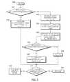
- FIG. 5is a flow diagram of a method 500 for monitoring an achieved motor torque produced by an electric motor in accordance with an exemplary embodiment.
- the motor speed of the electric motoris compared with a pre-determined threshold, as indicated at step 505 .
- the achieved motor torquecan be determined from either an electromagnetic torque relationship, such as the motor torque determination illustrated in FIG. 4 , or an estimated torque based on a balance of power (including compensation for one or more power losses) supplied to the electric motor.
- the MTM 200determines, for example, if the motor speed of the electric motor 102 is less than a calibrated low motor speed threshold (Cal_LowMotorSpeedBreakPoint). This threshold may be selected based on processor tolerances (e.g., based on division by low speed values) of the MTM 200 or the MCP 120 .
- a calibrated low motor speed thresholdCal_LowMotorSpeedBreakPoint
- the achieved motor torque (T achi )is determined from the electromagnetic torque relationship, as indicated at step 510 .
- the achieved motor torque (T achi )is determined to be the motor torque (T 1 ) based on the secured rotor position (sin( ⁇ ) and cos( ⁇ )) and the secured current sensor signals, which provide the three phase currents (i a , i b , and i c ), such as previously discussed in one exemplary embodiment (e.g., the motor torque determination shown in FIG. 4 ).
- the achieved motor torqueis determined from the estimated torque (e.g., based on the power balance and including loss compensation).
- the motor electrical power (P elec )is determined from a product of the DC bus voltage (V dc ) and the DC current (I dc ), as indicated at step 515 .
- One or more lossese.g., motor losses, inverter losses, or the like
- a motor torque (T 2 )is determined from a ratio of the compensated motor electrical power and the motor speed, as indicated at step 525 .
- the motor speedis compared with another threshold, as indicated at step 530 .
- the MTM 200determines if the motor speed of the electric motor 102 is greater than a calibrated high motor speed threshold (Cal_HighMotorSpeedBreakPoint). If the motor speed is greater than this threshold, the achieved motor torque is determined to be the motor torque (T 2 ) as indicated at step 535 .
- the achieved motor torqueis determined based on an interpolation of the motor torque (T 1 ) (e.g., based on the secured rotor position (sin( ⁇ ) and cos( ⁇ )) and the secured current sensor signals) and the motor torque (T 2 ) (e.g., based on the compensated motor electrical power) and the motor speed, as indicated at step 540 .
- the achieved motor torqueis compared with a torque command or requested torque, as indicated at step 545 .
- the MTM 200determines if the achieved motor torque (T achi ) is within a pre-determined margin (e.g., Cal_Threshold*) of the requested torque.
- a signalis transmitted (e.g., by the MTM 200 ), indicating a fault alarm, if the achieved torque (T achi ) is not within the pre-determined margin, as indicated at 550 .
- the achieved motor torqueis secure (e.g., Test Pass) if the achieved torque (T achi ) is within the pre-determined margin of the requested torque, as indicated at 555 .
- the pre-determined margin (Cal_Threshold*)may also be selected to be motor speed dependent.
- One or more portions of the method 500may be embodied in a software program comprising software instructions, instructions sets, executable modules, or the like, and arranged to run on a processor (e.g., the MCP 120 or the like) to monitor a motor torque produced by an electric motor in response to a torque command.
- a processore.g., the MCP 120 or the like
- the software programwhen installed and operating on the processor results in the processor performing or executing one or more portions of the software program.
Landscapes
- Engineering & Computer Science (AREA)
- Power Engineering (AREA)
- Life Sciences & Earth Sciences (AREA)
- Sustainable Development (AREA)
- Sustainable Energy (AREA)
- Transportation (AREA)
- Mechanical Engineering (AREA)
- Electric Propulsion And Braking For Vehicles (AREA)
- Control Of Ac Motors In General (AREA)
- Hybrid Electric Vehicles (AREA)
Abstract
Description
sin2(θ)+cos2(θ)=1 (eq. 1).
If the relationship shown in equation 1 is false (e.g., indicating an incorrect rotor position (θ), an incorrect look-up table value corresponding to the sine or cosine values of the rotor position (θ), or the like), the
T1=(3/2)p(ψdiq−ψqid) (eq. 2),
where p is the number of pole-pairs of the electric motor.
Claims (17)
Priority Applications (3)
| Application Number | Priority Date | Filing Date | Title |
|---|---|---|---|
| US11/853,113US7755310B2 (en) | 2007-09-11 | 2007-09-11 | Method and apparatus for electric motor torque monitoring |
| DE102008046240.3ADE102008046240B4 (en) | 2007-09-11 | 2008-09-08 | Method and device for monitoring the torque of an electric motor |
| CN2008102138364ACN101387688B (en) | 2007-09-11 | 2008-09-11 | Method and apparatus for electric motor torque monitoring |
Applications Claiming Priority (1)
| Application Number | Priority Date | Filing Date | Title |
|---|---|---|---|
| US11/853,113US7755310B2 (en) | 2007-09-11 | 2007-09-11 | Method and apparatus for electric motor torque monitoring |
Publications (2)
| Publication Number | Publication Date |
|---|---|
| US20090066281A1 US20090066281A1 (en) | 2009-03-12 |
| US7755310B2true US7755310B2 (en) | 2010-07-13 |
Family
ID=40431147
Family Applications (1)
| Application Number | Title | Priority Date | Filing Date |
|---|---|---|---|
| US11/853,113Expired - Fee RelatedUS7755310B2 (en) | 2007-09-11 | 2007-09-11 | Method and apparatus for electric motor torque monitoring |
Country Status (3)
| Country | Link |
|---|---|
| US (1) | US7755310B2 (en) |
| CN (1) | CN101387688B (en) |
| DE (1) | DE102008046240B4 (en) |
Cited By (51)
| Publication number | Priority date | Publication date | Assignee | Title |
|---|---|---|---|---|
| US20090125171A1 (en)* | 2007-11-08 | 2009-05-14 | Gm Global Technology Operations, Inc. | Processor security diagnostics for hybrid vehicle electric motor control system |
| US20110181216A1 (en)* | 2010-01-25 | 2011-07-28 | Sntech, Inc. | Speed-defined torque control |
| US20120109431A1 (en)* | 2010-11-01 | 2012-05-03 | Gm Global Technology Operations, Inc. | Robust motor torque performance diagnostics algorithm for electric drive systems in hybrid vehicles |
| US20140138079A1 (en)* | 2012-11-16 | 2014-05-22 | Us Well Services Llc | System for Pumping Hydraulic Fracturing Fluid Using Electric Pumps |
| US8831821B2 (en) | 2010-12-17 | 2014-09-09 | GM Global Technology Operations LLC | Controller area network message transmission disable testing systems and methods |
| US9122662B2 (en) | 2011-06-01 | 2015-09-01 | James Mason Faucett | Processor safety test control systems and methods |
| US9265585B2 (en) | 2012-10-23 | 2016-02-23 | Covidien Lp | Surgical instrument with rapid post event detection |
| US20160087561A1 (en)* | 2014-09-23 | 2016-03-24 | Hyundai Motor Company | Apparatus and method for controlling motor |
| US9611728B2 (en) | 2012-11-16 | 2017-04-04 | U.S. Well Services Llc | Cold weather package for oil field hydraulics |
| US9650871B2 (en) | 2012-11-16 | 2017-05-16 | Us Well Services Llc | Safety indicator lights for hydraulic fracturing pumps |
| US9650879B2 (en) | 2012-11-16 | 2017-05-16 | Us Well Services Llc | Torsional coupling for electric hydraulic fracturing fluid pumps |
| US9745840B2 (en) | 2012-11-16 | 2017-08-29 | Us Well Services Llc | Electric powered pump down |
| US9840901B2 (en) | 2012-11-16 | 2017-12-12 | U.S. Well Services, LLC | Remote monitoring for hydraulic fracturing equipment |
| US9893500B2 (en) | 2012-11-16 | 2018-02-13 | U.S. Well Services, LLC | Switchgear load sharing for oil field equipment |
| US9970278B2 (en) | 2012-11-16 | 2018-05-15 | U.S. Well Services, LLC | System for centralized monitoring and control of electric powered hydraulic fracturing fleet |
| US9995218B2 (en) | 2012-11-16 | 2018-06-12 | U.S. Well Services, LLC | Turbine chilling for oil field power generation |
| US10000197B2 (en) | 2015-08-10 | 2018-06-19 | Cummins Inc. | Mild hybrid powertrain controls |
| US10020711B2 (en) | 2012-11-16 | 2018-07-10 | U.S. Well Services, LLC | System for fueling electric powered hydraulic fracturing equipment with multiple fuel sources |
| US10036238B2 (en) | 2012-11-16 | 2018-07-31 | U.S. Well Services, LLC | Cable management of electric powered hydraulic fracturing pump unit |
| US10119381B2 (en) | 2012-11-16 | 2018-11-06 | U.S. Well Services, LLC | System for reducing vibrations in a pressure pumping fleet |
| US10232332B2 (en) | 2012-11-16 | 2019-03-19 | U.S. Well Services, Inc. | Independent control of auger and hopper assembly in electric blender system |
| US10254732B2 (en) | 2012-11-16 | 2019-04-09 | U.S. Well Services, Inc. | Monitoring and control of proppant storage from a datavan |
| US10280724B2 (en) | 2017-07-07 | 2019-05-07 | U.S. Well Services, Inc. | Hydraulic fracturing equipment with non-hydraulic power |
| US10284128B2 (en) | 2017-06-20 | 2019-05-07 | Regal Beloit America, Inc. | Controller for increasing torque output of electric motors |
| US10336212B2 (en) | 2013-11-27 | 2019-07-02 | Ford Global Technologies, Llc | Torque monitoring system and method |
| US10403116B2 (en) | 2017-06-20 | 2019-09-03 | General Electric Company | Electrical signature analysis of electrical rotating machines |
| US10408031B2 (en) | 2017-10-13 | 2019-09-10 | U.S. Well Services, LLC | Automated fracturing system and method |
| US10407990B2 (en) | 2012-11-16 | 2019-09-10 | U.S. Well Services, LLC | Slide out pump stand for hydraulic fracturing equipment |
| US10420577B2 (en) | 2014-03-31 | 2019-09-24 | Covidien Lp | Apparatus and method for tissue thickness sensing |
| US10526882B2 (en) | 2012-11-16 | 2020-01-07 | U.S. Well Services, LLC | Modular remote power generation and transmission for hydraulic fracturing system |
| US10598258B2 (en) | 2017-12-05 | 2020-03-24 | U.S. Well Services, LLC | Multi-plunger pumps and associated drive systems |
| US10648311B2 (en) | 2017-12-05 | 2020-05-12 | U.S. Well Services, LLC | High horsepower pumping configuration for an electric hydraulic fracturing system |
| US10648270B2 (en) | 2018-09-14 | 2020-05-12 | U.S. Well Services, LLC | Riser assist for wellsites |
| US10655435B2 (en) | 2017-10-25 | 2020-05-19 | U.S. Well Services, LLC | Smart fracturing system and method |
| US10928814B2 (en) | 2017-02-24 | 2021-02-23 | General Electric Technology Gmbh | Autonomous procedure for monitoring and diagnostics of machine based on electrical signature analysis |
| US11009162B1 (en) | 2019-12-27 | 2021-05-18 | U.S. Well Services, LLC | System and method for integrated flow supply line |
| US11035207B2 (en) | 2018-04-16 | 2021-06-15 | U.S. Well Services, LLC | Hybrid hydraulic fracturing fleet |
| US11067481B2 (en) | 2017-10-05 | 2021-07-20 | U.S. Well Services, LLC | Instrumented fracturing slurry flow system and method |
| US11114857B2 (en) | 2018-02-05 | 2021-09-07 | U.S. Well Services, LLC | Microgrid electrical load management |
| US11181107B2 (en) | 2016-12-02 | 2021-11-23 | U.S. Well Services, LLC | Constant voltage power distribution system for use with an electric hydraulic fracturing system |
| US11211801B2 (en) | 2018-06-15 | 2021-12-28 | U.S. Well Services, LLC | Integrated mobile power unit for hydraulic fracturing |
| US11208878B2 (en) | 2018-10-09 | 2021-12-28 | U.S. Well Services, LLC | Modular switchgear system and power distribution for electric oilfield equipment |
| US11449018B2 (en) | 2012-11-16 | 2022-09-20 | U.S. Well Services, LLC | System and method for parallel power and blackout protection for electric powered hydraulic fracturing |
| US11476781B2 (en) | 2012-11-16 | 2022-10-18 | U.S. Well Services, LLC | Wireline power supply during electric powered fracturing operations |
| US11542786B2 (en) | 2019-08-01 | 2023-01-03 | U.S. Well Services, LLC | High capacity power storage system for electric hydraulic fracturing |
| US11578577B2 (en) | 2019-03-20 | 2023-02-14 | U.S. Well Services, LLC | Oversized switchgear trailer for electric hydraulic fracturing |
| US11728709B2 (en) | 2019-05-13 | 2023-08-15 | U.S. Well Services, LLC | Encoderless vector control for VFD in hydraulic fracturing applications |
| US11959371B2 (en) | 2012-11-16 | 2024-04-16 | Us Well Services, Llc | Suction and discharge lines for a dual hydraulic fracturing unit |
| US12078110B2 (en) | 2015-11-20 | 2024-09-03 | Us Well Services, Llc | System for gas compression on electric hydraulic fracturing fleets |
| US12221872B2 (en) | 2014-10-14 | 2025-02-11 | U.S. Well Services, LLC | System and method for parallel power and blackout protection for electric powered hydraulic fracturing |
| US12442281B2 (en) | 2023-11-07 | 2025-10-14 | U.S. Well Services, LLC | Smart fracturing system and method |
Families Citing this family (39)
| Publication number | Priority date | Publication date | Assignee | Title |
|---|---|---|---|---|
| US8065050B2 (en)* | 2008-04-25 | 2011-11-22 | GM Global Technology Operations LLC | Method and apparatus for detecting an insufficient phase current in a permanent magnet synchronous motor |
| US8358095B2 (en)* | 2009-07-31 | 2013-01-22 | GM Global Technology Operations LLC | Method and system for testing electric motors |
| FR2953077B1 (en)* | 2009-11-26 | 2013-07-05 | Michelin Soc Tech | INVERTER FOR DRIVING A SYNCHRONOUS ELECTRIC MOTOR COMPRISING AN INTEGRATED REGULATOR. |
| AT509794B1 (en)* | 2010-04-29 | 2012-06-15 | Tttech Computertechnik Ag | PROCESS FOR THE SAFE OPERATION OF A CONVERTER FOR ROTATING ELECTRICAL MACHINES |
| CN102128698B (en)* | 2010-12-24 | 2012-05-02 | 哈尔滨工业大学 | Induction motor torque measuring method based on current sensor |
| US9566985B2 (en)* | 2011-02-08 | 2017-02-14 | GM Global Technology Operations LLC | Method and apparatus for monitoring a resolver in a torque machine |
| CN102694493B (en)* | 2011-03-23 | 2016-01-13 | 上海捷能汽车技术有限公司 | A kind of permanent magnet motor torque estimation method in fault model |
| DE102011075387A1 (en) | 2011-05-06 | 2012-11-08 | Robert Bosch Gmbh | Method and device for monitoring a torque of an electric motor |
| FR2985112B1 (en)* | 2011-12-21 | 2014-01-03 | Soc Tech Michelin | PILOT INVERTER WITH TORQUE ERROR DETECTOR |
| FR2985113B1 (en)* | 2011-12-21 | 2014-01-24 | Michelin Soc Tech | PILOT INVERTER WITH ABNORMAL TORQUE DETECTION DETECTOR |
| CN102437812B (en)* | 2011-12-30 | 2014-05-14 | 泰豪科技股份有限公司 | Dynamic magnetic link control method used for carrying out frequency conversion and speed regulation on asynchronous motor |
| FR2991526B1 (en) | 2012-05-30 | 2014-06-13 | Renault Sa | SYSTEM AND METHOD FOR MONITORING THE TORQUE OF A MOTOR VEHICLE ENGINE |
| FR3006949B1 (en) | 2013-06-17 | 2016-10-21 | Renault Sa | SYSTEM AND METHOD FOR MONITORING THE TORQUE PROVIDED BY THE ENGINE OF AN ELECTRIC OR HYBRID MOTOR VEHICLE. |
| CN103698702A (en)* | 2013-12-31 | 2014-04-02 | 江门市竞晖电器实业有限公司 | Multifunctional motor detection system |
| JP6290938B2 (en)* | 2014-02-04 | 2018-03-07 | 日立オートモティブシステムズ株式会社 | In-vehicle control device |
| US9448135B2 (en)* | 2014-07-16 | 2016-09-20 | Ford Global Technologies, Llc | Torque error detection and torque estimation system |
| CN104842818B (en) | 2014-08-13 | 2017-07-11 | 北汽福田汽车股份有限公司 | The torque monitoring method and its system of electric automobile |
| WO2016035575A1 (en)* | 2014-09-03 | 2016-03-10 | 株式会社堀場製作所 | Electric motor test system |
| CN104459537B (en)* | 2014-11-11 | 2017-05-17 | 奇瑞新能源汽车技术有限公司 | Health degree monitoring and diagnosing method of driving motor of electric vehicle |
| US10044310B2 (en)* | 2015-03-16 | 2018-08-07 | Deere & Company | Methods of auto tuning machine parameters and systems thereof |
| CN105553366B (en)* | 2015-12-23 | 2018-06-29 | 奇瑞汽车股份有限公司 | Rotor scaling method and device |
| CN105763128B (en)* | 2016-04-01 | 2018-09-11 | 北京新能源汽车股份有限公司 | Fault information processing method and system for rotary transformer decoding chip |
| CN105785268A (en)* | 2016-04-07 | 2016-07-20 | 中国海洋石油总公司 | Calibration method for slurry pulse generator of shearing valve |
| US10148209B2 (en)* | 2017-03-01 | 2018-12-04 | Ford Global Technologies, Llc | System and method for in-vehicle resolver alignment |
| JP6457583B2 (en) | 2017-05-02 | 2019-01-23 | ファナック株式会社 | Abnormality diagnosis apparatus and abnormality diagnosis method |
| FR3078214B1 (en)* | 2018-02-22 | 2020-03-20 | Valeo Equipements Electriques Moteur | METHOD FOR ASSISTING THE SETTING OF A HEAT ENGINE BY A ROTATING ELECTRIC MACHINE |
| US20200026269A1 (en)* | 2018-07-19 | 2020-01-23 | Aurora Flight Sciences Corporation | Performance monitoring system for an electric drive system |
| CN111277183A (en)* | 2018-11-20 | 2020-06-12 | 广东美的环境电器制造有限公司 | Motor rotating speed adjusting method, device, equipment and medium |
| CN109738795B (en)* | 2018-12-09 | 2023-06-09 | 西安航天精密机电研究所 | Multistage motor rotor magnetic pole detection device |
| GB2583343B (en)* | 2019-04-23 | 2023-11-29 | Trw Ltd | An electric motor apparatus |
| US11133771B2 (en)* | 2019-12-04 | 2021-09-28 | GM Global Technology Operations LLC | Integrated fault isolation and prognosis system for electric drive system |
| CN111351601A (en)* | 2020-04-28 | 2020-06-30 | 浙江睿驰同利汽车电子有限公司 | Method and device for testing torque of high-speed motor |
| CN112787561A (en)* | 2021-01-22 | 2021-05-11 | 广东省大湾区集成电路与系统应用研究院 | Torque monitoring method and device for vehicle motor and vehicle |
| CA3152029A1 (en)* | 2021-03-26 | 2022-09-26 | Taiga Motors Inc. | Locked rotor protection system and method for electric vehicle |
| CN113954639B (en)* | 2021-10-28 | 2023-10-27 | 中国第一汽车股份有限公司 | Method and device for determining torque capacity of motor wheel end, electronic equipment and storage medium |
| WO2022223854A1 (en)* | 2021-11-19 | 2022-10-27 | Chaves Garcia Jordi | Precision opening and closing mechanism for valves |
| CN114465534B (en)* | 2022-02-21 | 2022-10-11 | 小米汽车科技有限公司 | Motor rotor position determining method and device, medium and vehicle |
| CN114993541B (en)* | 2022-05-27 | 2023-09-22 | 中国第一汽车股份有限公司 | Method and system for testing starting static friction torque of 48V system |
| CN116620045A (en)* | 2023-06-28 | 2023-08-22 | 重庆长安汽车股份有限公司 | Motor torque control method and device and vehicle |
Citations (6)
| Publication number | Priority date | Publication date | Assignee | Title |
|---|---|---|---|---|
| US6163128A (en)* | 1999-08-20 | 2000-12-19 | General Motors Corporation | Method and drive system for controlling a permanent magnet synchronous machine |
| US20020105335A1 (en)* | 1999-09-16 | 2002-08-08 | Mir Sayeed A. | Current determination in a permanent magnet electric machine |
| US6495980B2 (en)* | 2000-09-28 | 2002-12-17 | Lg Electronics Inc. | Apparatus and method for sensing laundry amount in a washing machine |
| US6605912B1 (en)* | 1998-06-25 | 2003-08-12 | Delphi Technologies, Inc. | Method for controlling a permanent magnet motor |
| US6864662B2 (en)* | 2003-04-30 | 2005-03-08 | Visteon Global Technologies, Inc. | Electric power assist steering system and method of operation |
| US7049779B2 (en)* | 2004-09-09 | 2006-05-23 | Aisin A W Co., Ltd. | Motor drive control apparatus, motor drive control method and program of the same |
Family Cites Families (1)
| Publication number | Priority date | Publication date | Assignee | Title |
|---|---|---|---|---|
| EP0856427B1 (en) | 1996-07-30 | 2006-03-01 | Denso Corporation | Hybrid car controller |
- 2007
- 2007-09-11USUS11/853,113patent/US7755310B2/ennot_activeExpired - Fee Related
- 2008
- 2008-09-08DEDE102008046240.3Apatent/DE102008046240B4/ennot_activeExpired - Fee Related
- 2008-09-11CNCN2008102138364Apatent/CN101387688B/ennot_activeExpired - Fee Related
Patent Citations (6)
| Publication number | Priority date | Publication date | Assignee | Title |
|---|---|---|---|---|
| US6605912B1 (en)* | 1998-06-25 | 2003-08-12 | Delphi Technologies, Inc. | Method for controlling a permanent magnet motor |
| US6163128A (en)* | 1999-08-20 | 2000-12-19 | General Motors Corporation | Method and drive system for controlling a permanent magnet synchronous machine |
| US20020105335A1 (en)* | 1999-09-16 | 2002-08-08 | Mir Sayeed A. | Current determination in a permanent magnet electric machine |
| US6495980B2 (en)* | 2000-09-28 | 2002-12-17 | Lg Electronics Inc. | Apparatus and method for sensing laundry amount in a washing machine |
| US6864662B2 (en)* | 2003-04-30 | 2005-03-08 | Visteon Global Technologies, Inc. | Electric power assist steering system and method of operation |
| US7049779B2 (en)* | 2004-09-09 | 2006-05-23 | Aisin A W Co., Ltd. | Motor drive control apparatus, motor drive control method and program of the same |
Cited By (84)
| Publication number | Priority date | Publication date | Assignee | Title |
|---|---|---|---|---|
| US20090125171A1 (en)* | 2007-11-08 | 2009-05-14 | Gm Global Technology Operations, Inc. | Processor security diagnostics for hybrid vehicle electric motor control system |
| US20110181216A1 (en)* | 2010-01-25 | 2011-07-28 | Sntech, Inc. | Speed-defined torque control |
| US8587233B2 (en)* | 2010-01-25 | 2013-11-19 | Sntech, Inc. | Speed-defined torque control |
| US20120109431A1 (en)* | 2010-11-01 | 2012-05-03 | Gm Global Technology Operations, Inc. | Robust motor torque performance diagnostics algorithm for electric drive systems in hybrid vehicles |
| US8706346B2 (en)* | 2010-11-01 | 2014-04-22 | GM Global Technology Operations LLC | Robust motor torque performance diagnostics algorithm for electric drive systems in hybrid vehicles |
| US8831821B2 (en) | 2010-12-17 | 2014-09-09 | GM Global Technology Operations LLC | Controller area network message transmission disable testing systems and methods |
| US9122662B2 (en) | 2011-06-01 | 2015-09-01 | James Mason Faucett | Processor safety test control systems and methods |
| US10162312B2 (en) | 2012-10-23 | 2018-12-25 | Covidien Lp | Surgical instrument with rapid post event detection |
| US10838372B2 (en) | 2012-10-23 | 2020-11-17 | Covidien Lp | Surgical instrument with rapid post event detection |
| US9265585B2 (en) | 2012-10-23 | 2016-02-23 | Covidien Lp | Surgical instrument with rapid post event detection |
| US10731561B2 (en) | 2012-11-16 | 2020-08-04 | U.S. Well Services, LLC | Turbine chilling for oil field power generation |
| US11713661B2 (en) | 2012-11-16 | 2023-08-01 | U.S. Well Services, LLC | Electric powered pump down |
| US9611728B2 (en) | 2012-11-16 | 2017-04-04 | U.S. Well Services Llc | Cold weather package for oil field hydraulics |
| US9650871B2 (en) | 2012-11-16 | 2017-05-16 | Us Well Services Llc | Safety indicator lights for hydraulic fracturing pumps |
| US9650879B2 (en) | 2012-11-16 | 2017-05-16 | Us Well Services Llc | Torsional coupling for electric hydraulic fracturing fluid pumps |
| US9745840B2 (en) | 2012-11-16 | 2017-08-29 | Us Well Services Llc | Electric powered pump down |
| US9840901B2 (en) | 2012-11-16 | 2017-12-12 | U.S. Well Services, LLC | Remote monitoring for hydraulic fracturing equipment |
| US9893500B2 (en) | 2012-11-16 | 2018-02-13 | U.S. Well Services, LLC | Switchgear load sharing for oil field equipment |
| US9970278B2 (en) | 2012-11-16 | 2018-05-15 | U.S. Well Services, LLC | System for centralized monitoring and control of electric powered hydraulic fracturing fleet |
| US9995218B2 (en) | 2012-11-16 | 2018-06-12 | U.S. Well Services, LLC | Turbine chilling for oil field power generation |
| US12438480B2 (en) | 2012-11-16 | 2025-10-07 | U.S. Well Services, LLC | Wireline power supply during electric powered fracturing operations |
| US10020711B2 (en) | 2012-11-16 | 2018-07-10 | U.S. Well Services, LLC | System for fueling electric powered hydraulic fracturing equipment with multiple fuel sources |
| US10036238B2 (en) | 2012-11-16 | 2018-07-31 | U.S. Well Services, LLC | Cable management of electric powered hydraulic fracturing pump unit |
| US10107086B2 (en) | 2012-11-16 | 2018-10-23 | U.S. Well Services, LLC | Remote monitoring for hydraulic fracturing equipment |
| US10119381B2 (en) | 2012-11-16 | 2018-11-06 | U.S. Well Services, LLC | System for reducing vibrations in a pressure pumping fleet |
| US12404756B2 (en) | 2012-11-16 | 2025-09-02 | U.S. Well Services, LLC | Torsional coupling for electric hydraulic fracturing fluid pumps |
| US10232332B2 (en) | 2012-11-16 | 2019-03-19 | U.S. Well Services, Inc. | Independent control of auger and hopper assembly in electric blender system |
| US10254732B2 (en) | 2012-11-16 | 2019-04-09 | U.S. Well Services, Inc. | Monitoring and control of proppant storage from a datavan |
| US12228023B2 (en) | 2012-11-16 | 2025-02-18 | U.S. Well Services, LLC | Cable management of electric powered hydraulic fracturing pump unit |
| US12209490B2 (en) | 2012-11-16 | 2025-01-28 | U.S. Well Services, LLC | System for pumping hydraulic fracturing fluid using electric pumps |
| US10337308B2 (en) | 2012-11-16 | 2019-07-02 | U.S. Well Services, Inc. | System for pumping hydraulic fracturing fluid using electric pumps |
| US11959371B2 (en) | 2012-11-16 | 2024-04-16 | Us Well Services, Llc | Suction and discharge lines for a dual hydraulic fracturing unit |
| US11850563B2 (en) | 2012-11-16 | 2023-12-26 | U.S. Well Services, LLC | Independent control of auger and hopper assembly in electric blender system |
| US9410410B2 (en)* | 2012-11-16 | 2016-08-09 | Us Well Services Llc | System for pumping hydraulic fracturing fluid using electric pumps |
| US10407990B2 (en) | 2012-11-16 | 2019-09-10 | U.S. Well Services, LLC | Slide out pump stand for hydraulic fracturing equipment |
| US10408030B2 (en) | 2012-11-16 | 2019-09-10 | U.S. Well Services, LLC | Electric powered pump down |
| US11674352B2 (en) | 2012-11-16 | 2023-06-13 | U.S. Well Services, LLC | Slide out pump stand for hydraulic fracturing equipment |
| US10526882B2 (en) | 2012-11-16 | 2020-01-07 | U.S. Well Services, LLC | Modular remote power generation and transmission for hydraulic fracturing system |
| US11476781B2 (en) | 2012-11-16 | 2022-10-18 | U.S. Well Services, LLC | Wireline power supply during electric powered fracturing operations |
| US11449018B2 (en) | 2012-11-16 | 2022-09-20 | U.S. Well Services, LLC | System and method for parallel power and blackout protection for electric powered hydraulic fracturing |
| US11181879B2 (en) | 2012-11-16 | 2021-11-23 | U.S. Well Services, LLC | Monitoring and control of proppant storage from a datavan |
| US11136870B2 (en) | 2012-11-16 | 2021-10-05 | U.S. Well Services, LLC | System for pumping hydraulic fracturing fluid using electric pumps |
| US10686301B2 (en) | 2012-11-16 | 2020-06-16 | U.S. Well Services, LLC | Switchgear load sharing for oil field equipment |
| US11091992B2 (en) | 2012-11-16 | 2021-08-17 | U.S. Well Services, LLC | System for centralized monitoring and control of electric powered hydraulic fracturing fleet |
| US20140138079A1 (en)* | 2012-11-16 | 2014-05-22 | Us Well Services Llc | System for Pumping Hydraulic Fracturing Fluid Using Electric Pumps |
| US10927802B2 (en) | 2012-11-16 | 2021-02-23 | U.S. Well Services, LLC | System for fueling electric powered hydraulic fracturing equipment with multiple fuel sources |
| US11066912B2 (en) | 2012-11-16 | 2021-07-20 | U.S. Well Services, LLC | Torsional coupling for electric hydraulic fracturing fluid pumps |
| US10934824B2 (en) | 2012-11-16 | 2021-03-02 | U.S. Well Services, LLC | System for reducing vibrations in a pressure pumping fleet |
| US10947829B2 (en) | 2012-11-16 | 2021-03-16 | U.S. Well Services, LLC | Cable management of electric powered hydraulic fracturing pump unit |
| US10336212B2 (en) | 2013-11-27 | 2019-07-02 | Ford Global Technologies, Llc | Torque monitoring system and method |
| US10420577B2 (en) | 2014-03-31 | 2019-09-24 | Covidien Lp | Apparatus and method for tissue thickness sensing |
| US9413279B2 (en)* | 2014-09-23 | 2016-08-09 | Hyundai Motor Company | Apparatus and method for controlling motor |
| US20160087561A1 (en)* | 2014-09-23 | 2016-03-24 | Hyundai Motor Company | Apparatus and method for controlling motor |
| US12221872B2 (en) | 2014-10-14 | 2025-02-11 | U.S. Well Services, LLC | System and method for parallel power and blackout protection for electric powered hydraulic fracturing |
| US10000197B2 (en) | 2015-08-10 | 2018-06-19 | Cummins Inc. | Mild hybrid powertrain controls |
| US12085017B2 (en) | 2015-11-20 | 2024-09-10 | Us Well Services, Llc | System for gas compression on electric hydraulic fracturing fleets |
| US12078110B2 (en) | 2015-11-20 | 2024-09-03 | Us Well Services, Llc | System for gas compression on electric hydraulic fracturing fleets |
| US11181107B2 (en) | 2016-12-02 | 2021-11-23 | U.S. Well Services, LLC | Constant voltage power distribution system for use with an electric hydraulic fracturing system |
| US12092095B2 (en) | 2016-12-02 | 2024-09-17 | Us Well Services, Llc | Constant voltage power distribution system for use with an electric hydraulic fracturing system |
| US10928814B2 (en) | 2017-02-24 | 2021-02-23 | General Electric Technology Gmbh | Autonomous procedure for monitoring and diagnostics of machine based on electrical signature analysis |
| US10403116B2 (en) | 2017-06-20 | 2019-09-03 | General Electric Company | Electrical signature analysis of electrical rotating machines |
| US10284128B2 (en) | 2017-06-20 | 2019-05-07 | Regal Beloit America, Inc. | Controller for increasing torque output of electric motors |
| US10280724B2 (en) | 2017-07-07 | 2019-05-07 | U.S. Well Services, Inc. | Hydraulic fracturing equipment with non-hydraulic power |
| US11067481B2 (en) | 2017-10-05 | 2021-07-20 | U.S. Well Services, LLC | Instrumented fracturing slurry flow system and method |
| US11203924B2 (en) | 2017-10-13 | 2021-12-21 | U.S. Well Services, LLC | Automated fracturing system and method |
| US10408031B2 (en) | 2017-10-13 | 2019-09-10 | U.S. Well Services, LLC | Automated fracturing system and method |
| US10655435B2 (en) | 2017-10-25 | 2020-05-19 | U.S. Well Services, LLC | Smart fracturing system and method |
| US11959533B2 (en) | 2017-12-05 | 2024-04-16 | U.S. Well Services Holdings, Llc | Multi-plunger pumps and associated drive systems |
| US10598258B2 (en) | 2017-12-05 | 2020-03-24 | U.S. Well Services, LLC | Multi-plunger pumps and associated drive systems |
| US10648311B2 (en) | 2017-12-05 | 2020-05-12 | U.S. Well Services, LLC | High horsepower pumping configuration for an electric hydraulic fracturing system |
| US11114857B2 (en) | 2018-02-05 | 2021-09-07 | U.S. Well Services, LLC | Microgrid electrical load management |
| US11035207B2 (en) | 2018-04-16 | 2021-06-15 | U.S. Well Services, LLC | Hybrid hydraulic fracturing fleet |
| US12378865B2 (en) | 2018-04-16 | 2025-08-05 | U.S. Well Services, LLC | Hybrid hydraulic fracturing fleet |
| US11211801B2 (en) | 2018-06-15 | 2021-12-28 | U.S. Well Services, LLC | Integrated mobile power unit for hydraulic fracturing |
| US10648270B2 (en) | 2018-09-14 | 2020-05-12 | U.S. Well Services, LLC | Riser assist for wellsites |
| US11208878B2 (en) | 2018-10-09 | 2021-12-28 | U.S. Well Services, LLC | Modular switchgear system and power distribution for electric oilfield equipment |
| US11578577B2 (en) | 2019-03-20 | 2023-02-14 | U.S. Well Services, LLC | Oversized switchgear trailer for electric hydraulic fracturing |
| US12428942B2 (en) | 2019-03-20 | 2025-09-30 | U.S. Well Services, LLC | Oversized switchgear trailer for electric hydraulic fracturing |
| US11728709B2 (en) | 2019-05-13 | 2023-08-15 | U.S. Well Services, LLC | Encoderless vector control for VFD in hydraulic fracturing applications |
| US12385362B2 (en) | 2019-08-01 | 2025-08-12 | U.S. Well Services, LLC | High capacity power storage system for electric hydraulic fracturing |
| US11542786B2 (en) | 2019-08-01 | 2023-01-03 | U.S. Well Services, LLC | High capacity power storage system for electric hydraulic fracturing |
| US11009162B1 (en) | 2019-12-27 | 2021-05-18 | U.S. Well Services, LLC | System and method for integrated flow supply line |
| US12152711B2 (en) | 2019-12-27 | 2024-11-26 | U.S. Well Services, LLC | System and method for integrated flow supply line |
| US12442281B2 (en) | 2023-11-07 | 2025-10-14 | U.S. Well Services, LLC | Smart fracturing system and method |
Also Published As
| Publication number | Publication date |
|---|---|
| DE102008046240B4 (en) | 2020-07-09 |
| US20090066281A1 (en) | 2009-03-12 |
| CN101387688B (en) | 2011-06-15 |
| CN101387688A (en) | 2009-03-18 |
| DE102008046240A1 (en) | 2009-04-16 |
Similar Documents
| Publication | Publication Date | Title |
|---|---|---|
| US7755310B2 (en) | Method and apparatus for electric motor torque monitoring | |
| US9018881B2 (en) | Stator winding diagnostic systems and methods | |
| CN101927700B (en) | Methods and systems for diagnosing stator windings in an electric motor | |
| US8253365B2 (en) | Methods and systems for performing fault diagnostics for rotors of electric motors | |
| US8207694B2 (en) | Motor controller | |
| US8185342B2 (en) | Estimating rotor angular position and velocity and verifying accuracy of position sensor outputs | |
| US7977963B2 (en) | Methods, systems and apparatus for detecting abnormal operation of an inverter sub-module | |
| JP4793058B2 (en) | Fault diagnosis device for voltage sensor | |
| JP5055246B2 (en) | Control device for rotating electrical machine | |
| US9065376B2 (en) | Method for checking the plausibility of the torque of an electric machine and machine controller for controlling an electric machine and for carrying out the method | |
| US9473059B2 (en) | Control apparatus for AC motor | |
| US20090237013A1 (en) | Control Apparatus and Method for Motor Drive System | |
| US9172322B2 (en) | Control apparatus for AC motor | |
| US10826425B2 (en) | Drive device and control method for vehicle | |
| US9213065B2 (en) | Method and device for detecting a malfunction of an electric machine through the modulation of variables influencing the torque of the machine | |
| US11563225B2 (en) | System and method of controlling air compressor motor for fuel cell vehicle and system and method of controlling operation of fuel cell vehicle using same | |
| US11264928B2 (en) | Control device for electric motor and cable disconnection detection method | |
| US9425724B2 (en) | Motor abnormality detection apparatus | |
| JP6269328B2 (en) | Synchronous motor control device and vehicle control system including the same | |
| JP2020199945A (en) | Power generating system control device | |
| US11325478B2 (en) | Control apparatus, vehicle system, and control method | |
| US20150171777A1 (en) | Method for controlling driving motor |
Legal Events
| Date | Code | Title | Description |
|---|---|---|---|
| AS | Assignment | Owner name:GM GLOBAL TECHNOLOGY OPERATIONS, INC, MICHIGAN Free format text:ASSIGNMENT OF ASSIGNORS INTEREST;ASSIGNORS:WEST, STEPHEN T.;WANG, WEI D.;GLEASON, SEAN E.;REEL/FRAME:019807/0949;SIGNING DATES FROM 20070817 TO 20070820 Owner name:GM GLOBAL TECHNOLOGY OPERATIONS, INC, MICHIGAN Free format text:ASSIGNMENT OF ASSIGNORS INTEREST;ASSIGNORS:WEST, STEPHEN T.;WANG, WEI D.;GLEASON, SEAN E.;SIGNING DATES FROM 20070817 TO 20070820;REEL/FRAME:019807/0949 | |
| AS | Assignment | Owner name:UNITED STATES DEPARTMENT OF THE TREASURY, DISTRICT Free format text:SECURITY AGREEMENT;ASSIGNOR:GM GLOBAL TECHNOLOGY OPERATIONS, INC.;REEL/FRAME:022201/0405 Effective date:20081231 Owner name:UNITED STATES DEPARTMENT OF THE TREASURY,DISTRICT Free format text:SECURITY AGREEMENT;ASSIGNOR:GM GLOBAL TECHNOLOGY OPERATIONS, INC.;REEL/FRAME:022201/0405 Effective date:20081231 | |
| AS | Assignment | Owner name:CITICORP USA, INC. AS AGENT FOR BANK PRIORITY SECU Free format text:SECURITY AGREEMENT;ASSIGNOR:GM GLOBAL TECHNOLOGY OPERATIONS, INC.;REEL/FRAME:022554/0479 Effective date:20090409 Owner name:CITICORP USA, INC. AS AGENT FOR HEDGE PRIORITY SEC Free format text:SECURITY AGREEMENT;ASSIGNOR:GM GLOBAL TECHNOLOGY OPERATIONS, INC.;REEL/FRAME:022554/0479 Effective date:20090409 | |
| AS | Assignment | Owner name:GM GLOBAL TECHNOLOGY OPERATIONS, INC., MICHIGAN Free format text:RELEASE BY SECURED PARTY;ASSIGNOR:UNITED STATES DEPARTMENT OF THE TREASURY;REEL/FRAME:023124/0670 Effective date:20090709 Owner name:GM GLOBAL TECHNOLOGY OPERATIONS, INC.,MICHIGAN Free format text:RELEASE BY SECURED PARTY;ASSIGNOR:UNITED STATES DEPARTMENT OF THE TREASURY;REEL/FRAME:023124/0670 Effective date:20090709 | |
| AS | Assignment | Owner name:GM GLOBAL TECHNOLOGY OPERATIONS, INC., MICHIGAN Free format text:RELEASE BY SECURED PARTY;ASSIGNORS:CITICORP USA, INC. AS AGENT FOR BANK PRIORITY SECURED PARTIES;CITICORP USA, INC. AS AGENT FOR HEDGE PRIORITY SECURED PARTIES;REEL/FRAME:023155/0880 Effective date:20090814 Owner name:GM GLOBAL TECHNOLOGY OPERATIONS, INC.,MICHIGAN Free format text:RELEASE BY SECURED PARTY;ASSIGNORS:CITICORP USA, INC. AS AGENT FOR BANK PRIORITY SECURED PARTIES;CITICORP USA, INC. AS AGENT FOR HEDGE PRIORITY SECURED PARTIES;REEL/FRAME:023155/0880 Effective date:20090814 | |
| AS | Assignment | Owner name:UNITED STATES DEPARTMENT OF THE TREASURY, DISTRICT Free format text:SECURITY AGREEMENT;ASSIGNOR:GM GLOBAL TECHNOLOGY OPERATIONS, INC.;REEL/FRAME:023156/0264 Effective date:20090710 Owner name:UNITED STATES DEPARTMENT OF THE TREASURY,DISTRICT Free format text:SECURITY AGREEMENT;ASSIGNOR:GM GLOBAL TECHNOLOGY OPERATIONS, INC.;REEL/FRAME:023156/0264 Effective date:20090710 | |
| AS | Assignment | Owner name:UAW RETIREE MEDICAL BENEFITS TRUST, MICHIGAN Free format text:SECURITY AGREEMENT;ASSIGNOR:GM GLOBAL TECHNOLOGY OPERATIONS, INC.;REEL/FRAME:023162/0140 Effective date:20090710 Owner name:UAW RETIREE MEDICAL BENEFITS TRUST,MICHIGAN Free format text:SECURITY AGREEMENT;ASSIGNOR:GM GLOBAL TECHNOLOGY OPERATIONS, INC.;REEL/FRAME:023162/0140 Effective date:20090710 | |
| FEPP | Fee payment procedure | Free format text:PAYOR NUMBER ASSIGNED (ORIGINAL EVENT CODE: ASPN); ENTITY STATUS OF PATENT OWNER: LARGE ENTITY | |
| STCF | Information on status: patent grant | Free format text:PATENTED CASE | |
| AS | Assignment | Owner name:GM GLOBAL TECHNOLOGY OPERATIONS, INC., MICHIGAN Free format text:RELEASE BY SECURED PARTY;ASSIGNOR:UNITED STATES DEPARTMENT OF THE TREASURY;REEL/FRAME:025245/0780 Effective date:20100420 | |
| AS | Assignment | Owner name:GM GLOBAL TECHNOLOGY OPERATIONS, INC., MICHIGAN Free format text:RELEASE BY SECURED PARTY;ASSIGNOR:UAW RETIREE MEDICAL BENEFITS TRUST;REEL/FRAME:025314/0946 Effective date:20101026 | |
| AS | Assignment | Owner name:WILMINGTON TRUST COMPANY, DELAWARE Free format text:SECURITY AGREEMENT;ASSIGNOR:GM GLOBAL TECHNOLOGY OPERATIONS, INC.;REEL/FRAME:025324/0057 Effective date:20101027 | |
| AS | Assignment | Owner name:GM GLOBAL TECHNOLOGY OPERATIONS LLC, MICHIGAN Free format text:CHANGE OF NAME;ASSIGNOR:GM GLOBAL TECHNOLOGY OPERATIONS, INC.;REEL/FRAME:025781/0035 Effective date:20101202 | |
| FPAY | Fee payment | Year of fee payment:4 | |
| AS | Assignment | Owner name:GM GLOBAL TECHNOLOGY OPERATIONS LLC, MICHIGAN Free format text:RELEASE BY SECURED PARTY;ASSIGNOR:WILMINGTON TRUST COMPANY;REEL/FRAME:034185/0587 Effective date:20141017 | |
| MAFP | Maintenance fee payment | Free format text:PAYMENT OF MAINTENANCE FEE, 8TH YEAR, LARGE ENTITY (ORIGINAL EVENT CODE: M1552) Year of fee payment:8 | |
| FEPP | Fee payment procedure | Free format text:MAINTENANCE FEE REMINDER MAILED (ORIGINAL EVENT CODE: REM.); ENTITY STATUS OF PATENT OWNER: LARGE ENTITY | |
| LAPS | Lapse for failure to pay maintenance fees | Free format text:PATENT EXPIRED FOR FAILURE TO PAY MAINTENANCE FEES (ORIGINAL EVENT CODE: EXP.); ENTITY STATUS OF PATENT OWNER: LARGE ENTITY | |
| STCH | Information on status: patent discontinuation | Free format text:PATENT EXPIRED DUE TO NONPAYMENT OF MAINTENANCE FEES UNDER 37 CFR 1.362 | |
| FP | Lapsed due to failure to pay maintenance fee | Effective date:20220713 |