US7754022B2 - Wash chamber for appendage-washing method - Google Patents
Wash chamber for appendage-washing methodDownload PDFInfo
- Publication number
- US7754022B2 US7754022B2US12/330,145US33014508AUS7754022B2US 7754022 B2US7754022 B2US 7754022B2US 33014508 AUS33014508 AUS 33014508AUS 7754022 B2US7754022 B2US 7754022B2
- Authority
- US
- United States
- Prior art keywords
- nozzles
- wash chamber
- nozzle
- fluid
- cylinder
- Prior art date
- Legal status (The legal status is an assumption and is not a legal conclusion. Google has not performed a legal analysis and makes no representation as to the accuracy of the status listed.)
- Active
Links
Images


Classifications
- A—HUMAN NECESSITIES
- A47—FURNITURE; DOMESTIC ARTICLES OR APPLIANCES; COFFEE MILLS; SPICE MILLS; SUCTION CLEANERS IN GENERAL
- A47K—SANITARY EQUIPMENT NOT OTHERWISE PROVIDED FOR; TOILET ACCESSORIES
- A47K7/00—Body washing or cleaning implements
- A47K7/04—Mechanical washing or cleaning devices, hand or mechanically, i.e. power operated
- A—HUMAN NECESSITIES
- A61—MEDICAL OR VETERINARY SCIENCE; HYGIENE
- A61B—DIAGNOSIS; SURGERY; IDENTIFICATION
- A61B90/00—Instruments, implements or accessories specially adapted for surgery or diagnosis and not covered by any of the groups A61B1/00 - A61B50/00, e.g. for luxation treatment or for protecting wound edges
- A61B90/80—Implements for cleaning or washing the skin of surgeons or patients
- A—HUMAN NECESSITIES
- A61—MEDICAL OR VETERINARY SCIENCE; HYGIENE
- A61H—PHYSICAL THERAPY APPARATUS, e.g. DEVICES FOR LOCATING OR STIMULATING REFLEX POINTS IN THE BODY; ARTIFICIAL RESPIRATION; MASSAGE; BATHING DEVICES FOR SPECIAL THERAPEUTIC OR HYGIENIC PURPOSES OR SPECIFIC PARTS OF THE BODY
- A61H35/00—Baths for specific parts of the body
- A—HUMAN NECESSITIES
- A61—MEDICAL OR VETERINARY SCIENCE; HYGIENE
- A61L—METHODS OR APPARATUS FOR STERILISING MATERIALS OR OBJECTS IN GENERAL; DISINFECTION, STERILISATION OR DEODORISATION OF AIR; CHEMICAL ASPECTS OF BANDAGES, DRESSINGS, ABSORBENT PADS OR SURGICAL ARTICLES; MATERIALS FOR BANDAGES, DRESSINGS, ABSORBENT PADS OR SURGICAL ARTICLES
- A61L2/00—Methods or apparatus for disinfecting or sterilising materials or objects other than foodstuffs or contact lenses; Accessories therefor
- A61L2/16—Methods or apparatus for disinfecting or sterilising materials or objects other than foodstuffs or contact lenses; Accessories therefor using chemical substances
- A61L2/18—Liquid substances or solutions comprising solids or dissolved gases
- A—HUMAN NECESSITIES
- A61—MEDICAL OR VETERINARY SCIENCE; HYGIENE
- A61L—METHODS OR APPARATUS FOR STERILISING MATERIALS OR OBJECTS IN GENERAL; DISINFECTION, STERILISATION OR DEODORISATION OF AIR; CHEMICAL ASPECTS OF BANDAGES, DRESSINGS, ABSORBENT PADS OR SURGICAL ARTICLES; MATERIALS FOR BANDAGES, DRESSINGS, ABSORBENT PADS OR SURGICAL ARTICLES
- A61L2/00—Methods or apparatus for disinfecting or sterilising materials or objects other than foodstuffs or contact lenses; Accessories therefor
- A61L2/24—Apparatus using programmed or automatic operation
- A—HUMAN NECESSITIES
- A47—FURNITURE; DOMESTIC ARTICLES OR APPLIANCES; COFFEE MILLS; SPICE MILLS; SUCTION CLEANERS IN GENERAL
- A47K—SANITARY EQUIPMENT NOT OTHERWISE PROVIDED FOR; TOILET ACCESSORIES
- A47K2210/00—Combinations of water taps, soap dispensers and hand dryers
- A—HUMAN NECESSITIES
- A61—MEDICAL OR VETERINARY SCIENCE; HYGIENE
- A61H—PHYSICAL THERAPY APPARATUS, e.g. DEVICES FOR LOCATING OR STIMULATING REFLEX POINTS IN THE BODY; ARTIFICIAL RESPIRATION; MASSAGE; BATHING DEVICES FOR SPECIAL THERAPEUTIC OR HYGIENIC PURPOSES OR SPECIFIC PARTS OF THE BODY
- A61H2205/00—Devices for specific parts of the body
- A61H2205/06—Arms
- A61H2205/065—Hands
- Y—GENERAL TAGGING OF NEW TECHNOLOGICAL DEVELOPMENTS; GENERAL TAGGING OF CROSS-SECTIONAL TECHNOLOGIES SPANNING OVER SEVERAL SECTIONS OF THE IPC; TECHNICAL SUBJECTS COVERED BY FORMER USPC CROSS-REFERENCE ART COLLECTIONS [XRACs] AND DIGESTS
- Y10—TECHNICAL SUBJECTS COVERED BY FORMER USPC
- Y10T—TECHNICAL SUBJECTS COVERED BY FORMER US CLASSIFICATION
- Y10T29/00—Metal working
- Y10T29/49—Method of mechanical manufacture
- Y10T29/49826—Assembling or joining
- Y10T29/4984—Retaining clearance for motion between assembled parts
- Y—GENERAL TAGGING OF NEW TECHNOLOGICAL DEVELOPMENTS; GENERAL TAGGING OF CROSS-SECTIONAL TECHNOLOGIES SPANNING OVER SEVERAL SECTIONS OF THE IPC; TECHNICAL SUBJECTS COVERED BY FORMER USPC CROSS-REFERENCE ART COLLECTIONS [XRACs] AND DIGESTS
- Y10—TECHNICAL SUBJECTS COVERED BY FORMER USPC
- Y10T—TECHNICAL SUBJECTS COVERED BY FORMER US CLASSIFICATION
- Y10T29/00—Metal working
- Y10T29/53—Means to assemble or disassemble
Definitions
- the present inventionrelates to wash chambers for use in automated cleaning systems, and more particularly, to wash chambers used in automated washing devices used to clean at least a portion of an object or an appendage of a user.
- Touchless automated hand-washing devicesthat incorporate rotating cylinders are known and have been in use for some time. These devices are designed to wash and/or provide a proper amount of anti-microbial solution to a person's hand and forearm within in a set time.
- the cylinderscan be mounted in a free standing device and are adapted to receive the person's hand and forearm.
- the cylindersinclude an annulus or inner cavity that, in operation, is filled with cleaning fluid. As the inner cavity is filled, the cleaning fluid is forced out of a nozzle arrangement on the inner surface of the cylinder and into the interior of the cylinder. In order to provide greater coverage of the hand and forearm, the cylinders are rotated to provide a spray pattern.
- a nozzle arrangement known in the prior artis disclosed by U.S. Pat. No. 4,817,651 (“the '651 patent”).
- This patentdiscloses a three-set grouping of nozzles positioned on the interior surface of the rotating cylinder.
- a first set of nozzlesis positioned on a closed end of the cylinder opposite from an open end through which a person's hands are placed.
- the closed endincludes a frusto-conical shape that allows the first set of nozzles to be positioned such that cleaning fluid is sprayed toward the user's hand.
- the frusto-conical end portionmay include a drain through which spent cleaning fluid may exit the cylinder.
- a second set of nozzlesare arranged in a ring on the inner surface of the cylinder just inside the open end.
- the second set of nozzlesare angled downward, such that their spray is directed into the cylinder.
- a third set of nozzlesare positioned in a helical array along the length of the cylinder.
- the three-set nozzle arrangementhas several advantages. Firstly, the fingernails and the ends of the fingers receive a direct spray from the first set of nozzles. Secondly, the spray pattern that results from the second set of nozzles produces a “curtain” that prevents the cleaning fluid from being splashed or sprayed out of the cylinder. Lastly, the helical arrangement of nozzles along the length of the cylinder in combination the rotation of the cylinders results in debris and spent cleaning fluid being swept downward, toward the closed end of the cylinder. In particular, the third set of nozzles are disposed in a left-hand helical pattern which, when combined with the clock-wise rotation of the cylinders, results in a succession of sprays that travel down the arm from above the wrist towards the fingertips.
- the spray pattern that results from the nozzle arrangementdepends in part on the orientation and spray pattern of the individual nozzles. While the '651 patent contains little discussion of these details, U.S. Pat. No. 5,823,447 (“the '447 patent”) is directed to an angled fan nozzle for use with a rotating cleaning cylinder.
- the nozzle construction disclosed in the '447 patentproduces a flat “fan” pattern.
- cleaning fluidis ejected into the interior of the cylinder from a nozzle having a small square aperture.
- the spray of cleaning fluidspreads out through an angle while remaining substantially in a single plane.
- the nozzleis constructed such that the plane of the fan spray pattern is angled at 15 degrees with respect to the axis of the nozzle.
- the nozzlemay be positioned on the interior of the cylinder at a 15 degree tilt towards the closed end of the cylinder.
- the 15 degree angle of the fan spraycombines with the 15 degrees tilt of the nozzle, resulting in a fan spray directed partially downwards, towards the closed end of the cylinder.
- the fan sprayis directed downward at a 30 degree angle. This downwardly angled fan spray operates to direct spent cleaning fluid downwards, towards the closed end of the cylinder.
- a particular nozzlemay be positioned in a 0 degree rotational orientation, such that the flat fan spray is ejected from the nozzle “horizontally,” that is, in a plane parallel with the plane of the cylinder opening.
- a particular nozzlemay be positioned in the 90 degree orientation such that the flat fan spray is ejected “vertically,” that is, in a plane perpendicular to the plane of the cylinder opening.
- a particular nozzlecan be positioned at any angle between 0 and 90 degrees such that the flat fan spray has both a vertical and horizontal component.
- the present inventionis directed to a chamber, such as a wash chamber or cylinder, for use in connection with an automated fluid dispensing apparatus, such as a hand-washing machine.
- An embodiment of the wash cylinder described hereinincludes a plurality of nozzles disposed on the interior of the cylinder that deliver water and/or cleaning fluid as the cylinder rotates around a person's hand and forearm.
- the cylinderincludes an inner cylinder coupled to an outer cylinder. Water and/or cleaning fluid is delivered to the nozzles through an inner cavity located between the inner and outer cylinders.
- Wash cylinders in accordance with embodiments of the present inventioninclude features that allow for fast, reliable delivery of water and/or cleaning fluid.
- At least one embodiment of the present inventioncomprises a cylinder that includes a flow guidance structure disposed on a surface of the inner cylinder that reduces turbulence of the incoming fluid flow. Additionally, the cylinder may include a sealing mechanism that results in greater reliability under high pressure conditions.
- Cylinders in accordance with embodiments of the present inventioninclude drain holes sized to prevent fingers and/or jewelry from being caught while the cylinder is in motion.
- the drain holes or perforationsare preferably between in 1/32 inch to 1 ⁇ 4 inch in diameter.
- embodiments of the cylinderinclude structure that prevents fingers and/or jewelry from being caught between the rotating cylinder and non-moving parts of the machine.
- Cylinders in accordance with embodiments of the present inventioninclude features that produce an advantageous spray pattern.
- at least one embodiment of the present inventionuses a three-set nozzle arrangement having a bottom nozzle set, a top ring nozzle set, and a helical array nozzle set.
- the present inventionincludes a novel arrangement of helical nozzles that produce improved coverage of the hand and forearm of the user.
- a helical array of nozzles having progressively steeper rotational anglesis disclosed.
- embodiments of the present inventioninclude one or more off-helix nozzles.
- Embodiments of the present inventionmay comprise a nozzle strip or inlay that includes a plurality of nozzles along a preferred alignment, such as a linear alignment, a helical alignment, and/or a curved alignment.
- Embodiments of the presentsmay comprise a fluid conveyance feature to limit fluid volumes and decrease the cycle time.
- Embodiments of the present inventionmay comprise any one or more of the novel features described herein, including the in the Detailed Description, and/or shown in the drawings.
- each of the expressions “at least one of A, B and C”, “at least one of A, B, or C”, “one or more of A, B, and C”, “one or more of A, B, or C” and “A, B, and/or C”means A alone, B alone, C alone, A and B together, A and C together, B and C together, or A, B and C together.
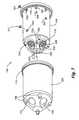
- FIG. 1is a perspective view of a cleaning station in accordance with embodiments of the present invention.
- FIG. 2Ais a schematic depiction of a portion of the cleaning station depicted in FIG. 1 ;
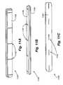
- FIG. 2Bis a perspective view of the wash cylinder shown in FIG. 2A ;
- FIG. 2Cis an additional perspective view of the wash cylinder shown in FIG. 2A ;
- FIG. 2Dis a close-up view of a portion of a cleaning station in accordance with embodiments of the present invention.
- FIG. 3Ais cross-sectional view of the wash cylinder and the seating assembly shown in FIG. 2A ;
- FIGS. 3B-Eare side elevation views of an inner cylinder in accordance with embodiments of the present invention.
- FIG. 4Ais a cross-sectional view of the closed end of the wash cylinder and the seating assembly shown in FIG. 2A ;
- FIG. 4Bis a detail view of a portion of FIG. 4A ;
- FIG. 5is a cross-sectional view of a prior art wash cylinder
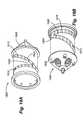
- FIG. 6is an exploded view of the seating assembly shown in FIG. 2A ;
- FIG. 7is an exploded perspective view of a wash cylinder in accordance with an embodiment of the present invention.
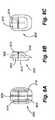
- FIG. 8Ais an elevation view of the inlet side of a square nozzle
- FIG. 8Bis a side elevation view of a square nozzle
- FIG. 8Cis an elevation view of outlet side of a square nozzle
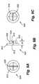
- FIG. 9Ais an elevation view of the inlet side of a straight nozzle
- FIG. 9Bis a side elevation view of a straight nozzle
- FIG. 9Cis an elevation view of outlet side of a straight nozzle
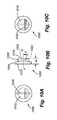
- FIG. 10Ais an elevation view of the inlet side of an angled nozzle
- FIG. 10Bis a side elevation view of an angled nozzle
- FIG. 10Cis an elevation view of outlet side of an angled nozzle
- FIGS. 11A-Care perspective views of a nozzle inlay
- FIG. 12Ais an elevation view of the inlet side of a nozzle inlay
- FIG. 12Bis a cross-sectional view of a nozzle inlay
- FIG. 12Cis an elevation view of the outlet side of a nozzle inlay
- FIG. 13is a perspective view of a nozzle inlay attached to a wash cylinder
- FIGS. 14A-Bare perspective views of an inner cylinder having a nozzle inlay
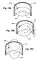
- FIGS. 15A-Care perspective views of the spray pattern produced by helical nozzles in accordance with embodiments of the present invention.
- FIG. 15Dis a perspective view of the spray pattern produced by a top ring nozzle in accordance with embodiments of the present invention.
- FIG. 16Ais a cut-away perspective view of the combined spray pattern produced by an exemplary nozzle arrangement in accordance with embodiments of the present invention.
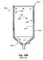
- FIG. 16Bis a cross-sectional view of a prior art wash cylinder
- FIG. 17is a exploded perspective view of an embodiment of the present invention having a fluid conveyance structure
- FIGS. 18A-Bare a perspective views of another embodiment of the present invention having a fluid conveyance structure
- FIGS. 19A-Bare perspective views of yet another embodiment of the present invention having a fluid conveyance structure
- FIG. 20is a cross-sectional view of cylinder in accordance with an embodiment of the present invention.
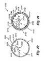
- FIG. 21is a cross-sectional view of wash chamber in accordance with an embodiment of the present invention.
- Embodiments of the present inventionare directed to one or more elements of a system and method for providing automated washing of an appendage of a person.
- embodiments of the present applicationare also applicable to other types of washing systems, including for example, boot-washing systems.
- cleaning effectivenesscan be improved from that of traditional sink and faucet systems, as well as existing automated cleaning stations by using an automated cleaning station with a novel wash cylinder construction.
- Various embodiments of the present inventionare described in the following text and in the drawings; however, it is to be understood that examples described herein are not meant to be limiting. Accordingly, the scope of the present invention includes modifications and alternatives to the example embodiments described in text and shown in the figures associated herewith.
- Cleaning stationsoperate to dispense one or more fluids, such as water, a cleaning fluid, such as soap, and/or a disinfectant, etc., while a person's hands are placed in a washbasin.
- a “washbasin” or “wash chamber”means a structure associated with the cleaning station where an appendage, such as a hand (or foot/boot) are cleaned, such as one or more wash cylinders, spray areas, pans, tubs, etc.
- Individualssuch as employees of a laboratory, food service related industry, or health care facility, may be instructed to wash their hands for a minimum amount of time that has been determined to be sufficient to provide a complete cleaning. In situations where hand (or boot) washing is required, or because of personal preferences, the user may be required to use (or otherwise desire to use) an automated cleaning station that incorporates a wash cylinder.
- the cleaning station 100includes a body 104 and a pair of washbasins, and more preferably, cylinders 108 residing within the body 104 for receiving an object.
- an “object”may refer to anything cleaned by the automated cleaning station.
- An objectmay be, for example, an appendage of a user, a tool, a boot, and/or an inanimate object, etc.
- inanimate objectmeans an object that is principally not a biological tissue, although biological matter may be associated with the inanimate object, for example, a virus, bacteria, and/or pieces of tissue on a tool.
- the various embodiments of the present inventionare discussed herein in connection with cleaning an appendage of a user. However, it should be understood that the various embodiments may be used in connection with other objects.
- the automated cleaning station 100is shown as a free standing machine. Alternatively, the automated cleaning station 100 may be incorporated into a counter top, wall, or other structure.
- Embodiments of the present inventioninclude at least one washbasin that comprises a cylinder 108 that rotates around a user's hand to clean the user's hand.
- the washbasin or wash chambermay comprise another shape.
- the cylindermay rotate either clockwise or counter-clockwise.
- Cleaningis performed by the application of fluids to the hands, wherein the fluids include water, a cleaning agent (such as soap), and/or a disinfectant, such as chlorhexidine gluconate (CHG).
- the fluidsare directed toward the user's hands through a series of nozzles, wherein the nozzles provide coverage of cleaning fluids to the user's hand to clean and rinse the user's hand.
- the userinserts their hand into the cylinder 108 and the cleaning station 100 automatically initiates a cleaning cycle by reading the presence of the user's hand within the cylinder 104 , such as by an optical sensor (not shown).
- At least one embodiment of the present inventionis directed to a novel wash cylinder for use in automated hand-washing machines.
- the rotating cylinder constructionis especially effective in providing a complete hand washing in a quick and reliable manner.
- the rotating cylindersmay be provided with a plurality of nozzle sets, such as a three-set nozzle arrangement.
- At least one embodiment of the present inventionfeatures a novel orientation and arrangement of cylinder nozzles.
- embodiments of the present inventioninclude other novel features of a wash cylinder that provide for improved flow of water and/or cleaning fluid in and out of the cylinder.
- the handsWhen a person places his or her hands in the wash cylinders 108 , they are washed and/or disinfected in a series of steps. Within approximately ten seconds the hands receive a (1) purge, (2) soap, and (3) rinse cycle.
- the purge cycleallows the water to reach the proper temperature.
- the soap cyclewashes and allows the soap or disinfectant to kill germs.
- the rinse cycleremoves the soap.
- FIG. 2Aprovides a view of part of an exemplary automated cleaning station 100 used by an employee whose hand 200 is being placed in position to be washed.
- One wash cylinder 108 and other components associated with the wash cylinder 108can be seen in FIG. 2A .
- the wash cylinder 108may be associated with a drive assembly 204 including a drive mechanism 208 and a drive belt 212 .
- the drive assembly 204operates to rotate the wash cylinder 108 when the automated cleaning station 100 is in use.
- a plurality of nozzles(not shown) disposed on the interior of the wash cylinder 108 spray water and/or cleaning fluid onto the hand 200 .
- the wash cylinder 108is interconnected to a seating assembly 216 that provides the wash cylinder 108 with a mounting within a receiving basin 220 .
- the receiving basin 220receives spent water and/or cleaning fluid that drains out of the wash cylinder 108 after use in connection with washing or rinsing the hand 200 .
- the spent fluidthen exits through the basin drain 222 towards the sewer or other disposal system.
- FIGS. 2B and 2Cshow detailed perspective views of the wash cylinder 108 .
- the wash cylinder 108includes an open end 224 and a frusto-conically shaped closed end 228 .
- the closed end 228includes a water inlet 232 and a plurality of drains 236 .
- the open end 224 of the wash cylinder 108features a rim 240 that includes a recessed portion 244 .
- the recessed portion 244is adapted to mate with a circular flange disposed on the automated cleaning station 100 .
- the circular flange 248can be seen with reference to FIG. 2D , which shows a close-up view of a portion of an automated cleaning station 100 , including a top portion of the wash cylinder 108 .
- the automated cleaning station 100may include a circular flange 248 that is operatively associated with the recessed portion 244 of the cylinder. This arrangement prevents a person's fingers, and/or loose items, such as jewelry, from being caught between the rotating cylinder and non-moving portions of the automated cleaning station 100 .
- FIG. 3Adepicts a cross-sectional view of the wash cylinder 108 and the seating assembly 216 .
- Cylinder 108preferably rotates around its rotational axis RA, such as in the direction of arrow R shown in FIG. 3A .
- At least one embodiment of the present inventionincludes nozzles arranged in a ring on the top end (the end proximate to the opening of the cylinder), nozzles arranged in a helical pattern along the length of the cylinder, one or more off-helix nozzles, and nozzles disposed on the bottom of the closed end of the cylinder.
- FIG. 3AA portion of the complete arrangement of nozzles can be seen in FIG. 3A .
- bottom nozzles 300are positioned on the closed end 228 of the wash cylinder 108 .
- Top ring nozzles 304are arranged just inside the open end 224 of the wash cylinder 108 .
- Helical nozzles 308are positioned in an array along the length of the wash cylinder 108 .
- Four helical nozzles 308are shown in FIG. 3A .
- the wash cylinder 108may include additional helical nozzles 308 disposed on portions of the cylinder 108 that are not visible in the cross sectional view shown in FIG. 3A .
- the complete wash cylinder 108may include any number of helical nozzles, such as for example, five, six, seven, eight, nine, or ten. Additionally, embodiments of the present invention include one or more off-helix nozzles 312 .
- the cylinder 108includes or comprises an appendage receiving member having an inner member, such as inner cylinder 316 , and an outer member, such as outer cylinder 320 .
- the appendage receiving member and its inner and outer membermay be cylindrical or substantially cylindrical in shape, or may comprise another shape.
- An annular cavity 324is established between the inner cylinder 316 and the outer cylinder 320 .
- the annular cavity 324is preferably 0.070 inches wide.
- the annular cavity 324may be between 1/16 inch and 3/16 inch wide.
- the length L of the wash cylinder 108is preferably 11.490 inches.
- the length L of wash cylinder 108may be between 12.5 and 10.5 inches.
- the diameter D of the wash cylinder 108is preferably 6.580 inches. Alternatively, the diameter D of the wash cylinder 108 but may be between 7.5 and 5.5 inches.
- the above noted dimensionsare example dimensions for a wash cylinder 108 used to clean a person's hands and are not meant to be limiting. Cylinders having different dimensions are within the scope of the present invention. For example, larger cylinders can be used to clean a person's hand, forearm and upper arm. Also, as those skilled in the art will appreciate, different sized cylinders can be used to clean a person's foot and/or lower leg.
- FIGS. 3B-Eshow a complete nozzle arrangement
- FIGS. 3B-3Eshows a nozzle arrangement having eight helical nozzles 308 a - h .
- the views shown in FIGS. 3B-Eare 90 degrees apart, such that FIGS. 3B-E together show a complete 360 degree view of the inner cylinder 316 .
- the inner cylinder 316includes four bottom nozzles 300 ; eight top ring nozzles 304 ; eight helical nozzles 308 a - h , and two off-helix nozzles 312 . It should be understood that alternative embodiments of the present invention may include any suitable number of top ring nozzles, helical nozzles, off-helix nozzles and bottom nozzles.
- the annular cavity 324 established between the inner cylinder 316 and the outer cylinder 320is filled with water and/or cleaning fluid under pressure. Fluid enters the annular cavity 324 through the fluid inlet 232 disposed on the closed end 228 of the wash cylinder 108 .
- the fluid inlet 232includes a circular hole 321 in the outer cylinder 320 and a tubular portion 322 depending therefrom.
- the annular cavity 324fills and becomes pressurized. The pressure within the annular cavity 324 forces the fluid through the nozzles 300 , 304 , 308 a - h and 312 and into the interior of the wash cylinder 108 .
- a spray patternis established in the interior of the wash cylinder 108 .
- Fluidis removed from the wash cylinder 108 through the drains 236 disposed on the closed end 228 .
- the spay pattern established in the interior of the cylinder 108is discussed in greater detail below.
- embodiments of the present inventioninclude a novel orientation and arrangement of nozzles that produce an advantageous spray pattern having greater coverage of the hand 200 and forearm of a user.
- FIG. 4Ashows a close-up view of the closed end 228 of an embodiment of a wash cylinder 108 .
- fluidenters through the fluid inlet 232 .
- flow arrows 404 a and 404 bthe fluid flows into the annular cavity 324 .
- FIG. 4Ais a cross-sectional view of the cylinder 108 , only a portion of the fluid flow it depicted. In reality, the fluid flowing in from the inlet 232 spreads out in all directions to enter the annular cavity 324 .
- FIG. 4Ashows the flow of fluid through only one nozzle 308 h , it should be understood that similar flow exists in other nozzles associated with the wash cylinder.
- the tip of the closed end 228 of the inner cylinder 316includes a flow guidance structure or protrusion 420 .
- the protrusion 420is disposed on the inner cylinder 316 in line with the inlet 232 . Fluid is deflected radially by the protrusion 420 as it enters through the inlet 232 into the cavity 324 between the inner cylinder 316 and the outer cylinder 320 . This deflection serves to direct the flow of fluid and leads to a decreased level of turbulence in the fluid.
- FIG. 5depicts the situation that results from fluid entering a cavity 500 without being deflected radially.
- the fluid 502flows perpendicularly into a surface 506 of an inner cylinder 504 .
- the fluid 502does not flow smoothly. This leads to a loss of fluid pressure and a longer time needed to fill the cylinder.
- the fluid guidance structure 420includes a symmetrical sloped surface that has its greatest location of projection 421 disposed in line with a central axis around which the wash cylinder 108 rotates.
- sloped surface 436 of protrusion 420is offset from the rotational axis RA of the cylinder 108 by an angle ⁇ , where angle ⁇ is less than 90°. The speed in which the cavity is filled is important for delivering a complete hand washing in a timely manner.
- the cleaning station 100utilizes a number of different cycles, such as wash and rinse, that require different fluids to flow in and out of the cylinder.
- cyclessuch as wash and rinse
- the overall time needed to complete the total number of cyclesis important for providing a reliable handwashing. It has been shown that people are more likely to wash their hands if the handwashing can be accomplished in a short period of time. Accordingly, for a number reasons, a reduction in the time needed to fill and pressurize the cavity 324 , as accomplished by the protrusion 420 , achieves an improved and more desirable handwashing.
- the seating assembly 216may become partially or totally submerged before the fluid exits through the basin drain 222 . Accordingly, the seating assembly 216 is designed to operate in the presence of water and/or cleaning fluid. Components of the seating assembly 216 can be better seen in the exploded view shown in FIG. 6 . As can be seen therein, the seating assembly 216 includes a bearing 600 and an O-ring 604 that are positioned within a bearing block 608 . The bearing block is secured by means of a washer 612 and a panel nut 616 or other retaining hardware. The O-ring 604 operates to prevent fluid from entering the seating assembly 216 .
- the connection between the wash cylinder 108 and the automated cleaning station 100operates more effectively over a longer lifetime.
- the O-ring 604provides for a smoother connection when the cylinder 108 is mounted to the seating assembly 216 , in comparison to previous friction-fit designs. Additionally, the O-ring 604 provides a seal between the bearing block 608 and the fluid inlet 232 preventing water and/or cleaning fluids from being lost in the receiving basin 220 .
- the appendage receiving membersuch as wash cylinder 108
- the appendage receiving memberincludes an inner member, such as inner cylinder 316 , assembled to or integrated with an outer member, such as outer cylinder 320 .
- the wash cylinder 108features a water tight seal between the inner cylinder 316 and the outer cylinder 320 .
- the inner cylinder 316includes protrusions 700 that contain holes 704 adapted to receive a connector, such as bolts or screws. The protrusions 700 are received in recessed portions 708 disposed on the outer cylinder 320 .
- the inner cylinder 316is interconnected to the outer cylinder 320 by screws that are driven through holes 712 in the recessed portions 708 into the holes 704 in the protrusions 700 . Additionally, there are no hardware holes or protrusions on the inside of the inner cylinder that can cause harm to a user's hand.
- the water tight seal between the inner cylinder 316 and the outer cylinder 320may include other connecting mechanisms such as rivets and/or glue.
- the outer cylinder 320includes a flange 714 that is adapted for engagement with a lip 718 disposed on the inner cylinder 316 .
- An O-ring(not shown) is positioned within the lip 718 to provide a seal between the inner cylinder 316 and the outer cylinder 320 .
- the combination of the flange 714 , lip 718 and the O-ringprovides a seal that can resist high pressures exerted by fluid in the cavity between the cylinders 316 and 320 . (The interconnection between the lip 718 and the flange 714 can be seen in FIG.
- the cavity 324may expand under high pressure conditions creating an opening between the cylinders 316 and 320 through which fluid may leak. A decreased fluid pressure will then be available at the nozzles and, accordingly, an inferior hand washing will result. Additionally, fluid leakage may result in unwanted fluid flow into portions of the automated cleaning station 100 that are unconnected to a drain 236 and/or are otherwise unable to receive fluid. Resulting fluid accumulation can lead to rust, electrical shorts, and/or other damage to components of the automated cleaning station 100 . Accordingly, the seal structure described above provides a configuration that maintains fluid pressures and prevents undesirable leakage.
- the drains 236are disposed on the inner cylinder 316 and include a drain wall 716 .
- each drain wall 716is received in, and protrudes through a hole 720 in the outer cylinder 320 .
- An O-ring(not shown) may be positioned around each drain wall 716 to provide a seal between the inner cylinder 316 and the outer cylinder 320 .
- the surface of each drain 236includes a plurality of perforations 724 , which are large enough to allow fluid to pass through, and yet small enough to prevent a finger or small object from passing through.
- This drain configurationprevents a person's finger and/or their jewelry from being caught in the drain 236 when the wash cylinder is in motion.
- the relatively small size of the perforations 724prevents trash that may be deposited in the wash cylinder 108 from working its way into and clogging the drainage system.
- the nozzles associated with the wash cylinder 108are connected to the inner cylinder 316 .
- the inner cylinder 316includes a plurality of shaped holes that are adapted to receive a nozzle of a particular shape. (Alternatively, the nozzle may simply be a slit in the in wall of the inner cylinder 316 .)
- the top ring nozzles 304 , the helical nozzles 308 a - h and the off-helix nozzles 312have a “hat-shaped” construction adapted to fit in a similarly shaped hole in the inner cylinder. As can be seen in FIG.
- an off-helix nozzle 312is shown removed from its shaped hole 732 a .
- a top ring nozzle 304is shown removed from its shaped hole 732 b .
- the bottom nozzles 300have a “square” construction. As can be seen in FIG. 7 , a bottom nozzle 300 can be seen residing in its shaped hole 732 c.
- the bottom nozzles 300are implemented as square nozzles 800 .
- the square nozzle 800 configurationis illustrated in FIGS. 8A-C .
- the square nozzle 800includes an inlet side 804 having an inlet slot 808 , and an outlet side 812 having an outlet slot 816 .
- the inlet slot 808 and the outlet slot 816are perpendicular to each other.
- the square nozzle 800has a shape that is adapted to be received in a similarly shaped nozzle hole 732 c associated with the inner cylinder 316 .
- the inlet side 804is flush with the outer surface 424 of the inner cylinder 316
- the outlet side 812is flush with the inner surface 428 of the inner cylinder 316 .
- the water and/or cleaning fluidflows from the annular cavity 324 through the slots 808 and 816 of the square nozzle 800 .
- the bottom nozzles 300are placed in a position wherein their spray may directly impact the fingernails and finger tips of the hand
- the bottom nozzles 300shown in FIG. 8A-C , include ribs 814 disposed on the inlet side 804 of nozzle 800 .
- the ribs 814prevent the nozzle from being pushed out and dislodged during operation of the wash cylinder.
- the ribs 814engage the inner wall 432 of the outer cylinder 320 when the inner cylinder 316 is installed in the outer cylinder 320 .
- any of the nozzles disclosed hereinmay incorporate a one or more ribs 814 .
- the wash cylinder 108may incorporate both a “straight” type nozzle and an “angled” type nozzle, both of which have a hat-shaped construction, as described above.
- the difference between the straight nozzle and the angled nozzleis in the orientation of internal slots that form a passageway in which fluid travels from the inlet side to the outlet side.
- Both the straight and the angled nozzlesproduce a flat “fan” spray pattern that emerges at a small-area opening on the outlet side and spreads out through an angle while remaining substantially in one plane.
- the angle at which the fan spray emerges from the straight nozzle 900(described in connection with FIGS. 9A-C ) is different from the angle at which the fan spray emerges from the angled nozzle 1000 (described in connection with FIGS. 10A-C ).
- FIGS. 9A-CAn exemplary straight nozzle 900 designed to be received in the shaped holes 732 a , is illustrated in FIGS. 9A-C .
- the straight nozzles 900include a first or larger-diameter disk 904 integrated with or interconnected to second or smaller-diameter disk 908 .
- the inlet side 912 of the straight nozzle 900corresponds to the outside face of the larger-diameter disk 904 .
- the outlet side 916 of the straight nozzle 900corresponds to the outside face of the smaller-diameter disk 908 .
- FIG. 4Awhen incorporated into the inner cylinder 316 , the inlet side 912 is flush with the outer surface 424 of the inner cylinder 316 , and the outlet side 916 is flush with the inner surface 428 of the inner cylinder 316 .
- the straight nozzle 900features two intersecting circular shaped slots 920 and 924 that together form a passageway through which fluid may travel.
- the inlet slot 920begins on the inlet side 912 and continues through a portion of the width W of the straight nozzle 900 .
- the outlet slot 924begins on the outlet side 916 and continues through a portion of the width W of the straight nozzle 900 such that an intersection is provided with the inlet slot 920 .
- the inlet slot 920includes a thin rectangularly-shaped inlet opening 928 in the inlet side 912 of the straight nozzle 900 .
- FIG. 9Athe inlet slot 920 includes a thin rectangularly-shaped inlet opening 928 in the inlet side 912 of the straight nozzle 900 .
- the outlet slot 924includes a thin rectangularly-shaped outlet opening 932 in the outlet side 916 of the straight nozzle 900 .
- the inlet opening 928 and the outlet opening 932are approximately perpendicular.
- the fan spray produced by the straight nozzle 900emerges at a 90 degree angle with respect to the outlet side 916 of the straight nozzle 900 .
- the helical nozzles 308 a - h and the off-helix nozzles 312are implemented as straight nozzles 900 .
- FIG. 10A through FIG. 10Cprovide illustrations of the angled nozzle 1000 .
- the angled nozzle 1000includes the hat-shaped construction described above, including a larger diameter disk 1004 and a smaller diameter disk 1008 .
- the angled nozzleadditionally includes an inlet side 1012 and an outlet side 1016 .
- the angled nozzle 1000features two intersecting circular shaped slots 1020 and 1024 that together form a passageway through which fluid may travel.
- the inlet slot 1020begins on the inlet side 1012 and continues through a portion of the width W of the angled nozzle 1000 .
- the outlet slot 1024begins on the outlet side 1016 and continues through a portion of the width W of the angled nozzle 1000 such that an intersection is provided with the inlet slot 1020 .
- the angled nozzle 1000includes an outlet slot 1024 disposed at an angle ⁇ with respect to the axis A of the nozzle 1000 .
- the angle between the outlet slot 1024 and the axis Ais preferably 15 degrees.
- the angle between the outlet slot 1024 and the axis Amay be between 5 and 30 degrees.
- the angle between the outlet slot 1024 and the axis Amay be between 1 and 90 degrees.
- the inlet slot 1020includes a thin rectangularly shaped inlet opening 1028 in the inlet side 1012 of the angled nozzle 1000 .
- the outlet slot 1024terminates in a thin rectangularly shaped outlet opening 1032 in the outlet side 1016 of the angled nozzle 1000 .
- the inlet opening 1028 and the outlet opening 1032are approximately perpendicular.
- the top ring nozzlesare implemented as angled nozzles 1000 .
- the top ring nozzles 304(shown in FIG. 3A ) are angled into the interior of the cylinder such that they provide a fluid “curtain” that minimizes the spraying and splashing of fluid out of the cylinder 108 and provides washing at the wrist of the hand 200 .
- the nozzle holes 732 a - cmay be a particular shape that is adapted to receive a particular nozzle.
- nozzles holes 732 a - bare adapted to receive hat-shaped nozzles (either a straight nozzle 900 or an angled nozzle 1000 ) and may include a smaller diameter portion adapted to fit only the smaller diameter-disk 904 , 1004 . Accordingly, it is only possible to insert the nozzle in one direction.
- the top ring nozzles 304may be of a different size than the helical nozzles 308 a - h .
- the nozzle holes 732 b associated with the top ring nozzles 304are of a different size than the nozzle holes 732 a associated with the helical nozzles 308 a - h . Accordingly, a nozzle to be used in connection with helical nozzle 308 a - h may not be inadvertently placed in a nozzle hole 732 b adapted to receive a top ring nozzle 304 , and vice versa. These nozzle features provide ease for manufacturing while improving quality of flow because the nozzles are located in their proper position.
- a particular nozzledoes not extend away from the inner surface 428 of the wash cylinder 108 . Accordingly, they do not present any protrusions that would contact the hand during a wash. Additionally, as the nozzles 900 , 1000 are not angled with respect to the wall of the cylinder, the width of the cavity may be manufactured at a smaller width than was possible in previous designs. Additionally, the complexity of the mold tool of assembly and cylinder is decreased.
- straight nozzles 900typically used to implement the helical nozzles 308 a - h and the off-helix nozzles 312
- the angled nozzles 1000typically used to implement the top ring nozzles 304
- a plurality of nozzlesmay be integrally formed within a single nozzle “inlay,” in order to provide greater ease in assembling a wash cylinder 108 .
- FIGS. 11A-Cdepict an example of a nozzle inlay 1100 in accordance with embodiments of the present invention. In particular, FIGS.
- FIGS. 12A-Cshow the exterior structure of a nozzle inlay 1100 having five nozzles 1102 .
- the nozzle inlay 1100may have a different number of nozzles, such as two, three, four, six or seven.
- the nozzle inlay 1100has a single relatively long nozzle (not shown).
- the nozzle inlay 1100has an inlet side 1104 and an outlet side 1108 .
- FIGS. 12A-Cshow the internal structure of the nozzle inlay 1100 , including inlet slots 1204 and outlet slots 1208 . While the nozzle inlay 1100 shown in FIGS. 11A-C and FIGS. 12A-C includes nozzles of the straight type, it should be understood that nozzle inlays that include nozzles of the angled type are within the scope of the invention.
- wash cylinders 108 that incorporate nozzle inlayspreferably include a channel or recessed portion 1300 that is adapted to receive the nozzle inlay 1100 . Accordingly, multiple nozzles may be installed in the cylinder 108 in one step.
- the inlet side 1204is flush with the outer surface 424 of the inner cylinder 316
- the outlet side 1208is flush with the inner surface 428 of the inner cylinder 316 .
- FIG. 14A and FIG. 14Bdepict various nozzle inlays incorporated into an inner cylinder 316 .
- the inner cylinder 316may include a curved type nozzle inlay 1400 that is disposed perpendicular to the axis of the cylinder, and a straight type nozzle inlay 1404 that is disposed parallel to the axis of the cylinder.
- the helical nozzles 308 a - hmay be implemented with straight nozzles 900 and each nozzle disposed at a different angular orientation in order to provide a spray pattern having improved coverage of the user's hand and forearm.
- the helical nozzles 308 a - hmay be disposed at different angular orientations around the axis A of the nozzle to produce a variety of different angled spray patterns.
- the different angular orientationsare achieved by the placement of the helical nozzles 308 a - h at different angles within its nozzle hole 732 a .
- the different angular orientations of the nozzlesmay be built into the nozzle inlay 1100 itself.
- the spray pattern produced by disposing a straight nozzle 900 at an angular orientation with respect to its axis Ais different from the spray pattern produced by the angled nozzle 1000 .
- a “pitch” and a “roll” angleare defined.
- the “pitch angle”is described as being the angle away from the axis of the nozzle.
- a “roll angle”is defined as being around the axis A of the nozzle.
- the internal structure of the nozzlesdetermines the pitch angle of the spray pattern that is produced.
- the angled slots 1020 and 1024 of the angled nozzle 1000result in a spray pattern having, for example, a 15 degree pitch angle.
- the orientation of the internal slots 920 and 924 of the straight nozzle 900result in spray pattern having a 0 degree pitch angle.
- the roll angleis determined by the orientation in which the nozzle is placed in its nozzle hole 732 a .
- a nozzle oriented such that its outlet opening 932 or 1032 lies in a plane parallel to a plane defined by the opening of the cylinder 108has a spray pattern with a 0 degree roll angle.
- the nozzles depicted thereinproduce spray patterns having various pitch and roll angles.
- the top ring nozzles 304may be implemented with angled nozzles 1000 .
- the nozzles 304are oriented such that their inlet openings 1028 are “vertical.”
- their outlet openings 1032are then “horizontal” or, equivalently, in a plane parallel to a plane defined by the opening of the cylinder 108 . Accordingly, and by way of example and not limitation, each nozzle 304 produces a fan spray having a 15 degree pitch angle and a 0 degree roll angle.
- the helical nozzles 308 a - hmay be implemented using straight nozzles 900 . As can seen from FIGS. 3B-E , the nozzles 308 a - h are oriented at various rotational angles. Accordingly, the helical nozzles 308 a - h produce fan sprays having 0 degree pitch angle and various roll angles.
- the helical nozzle 308 ahas a roll angle of approximately 0 to 10 degrees.
- the helical nozzle 308 amay be disposed at shallow angle defined herein as being between 0 degrees and 45 degrees.
- the helical nozzle 308 bhas a roll angle of approximately 10 to 20 degrees.
- FIGS. 15A-Dshow individual spray patterns produced by various nozzles.
- FIG. 15Ashows the spray pattern 1500 produced by the helical nozzle 308 a .
- the spray pattern produced by this nozzlehas 0 degree pitch angle and approximately a 0 degree roll angle.
- FIG. 15Bshows the spray pattern 1504 produced by helical nozzle 308 b , which has a 0 degree pitch angle and a 15 degree roll angle.
- FIG. 15Cshows the spray pattern 1508 produced by nozzle 308 h , which has a 0 degree pitch angle and a 90 degree roll angle.
- FIG. 15Ashows the spray pattern 1500 produced by the helical nozzle 308 a .
- the spray pattern produced by this nozzlehas 0 degree pitch angle and approximately a 0 degree roll angle.
- FIG. 15Bshows the spray pattern 1504 produced by helical nozzle 308 b , which has a 0 degree pitch angle and a 15 degree roll angle.
- FIG. 15Cshows the spray pattern 15
- FIG. 15Dshows the spray pattern 1512 produced by the top ring nozzle 304 , which has 15 degree pitch angle and a 0 degree roll angle.
- FIG. 15Bshows helical nozzle 308 b having a 0 degree pitch angle and a 15 degree roll angle
- FIG. 15Dshows top ring nozzle 304 having a 15 degree pitch angle and a 0 degree roll angle.
- FIG. 16shows a simplified illustration of the combined spray pattern that results from the nozzle arrangement in accordance with the embodiment of the present invention shown in FIGS. 3B-E .
- the shaded portionrepresents the area having improved spray coverage.
- the dotted linesrepresent individual spray patterns associated with the helical nozzles 308 a - h .
- the fan spray patterns associated with the helical nozzles 308begin with an upper-most nozzle 308 a having a spray pattern that is oriented approximately at 0 degree roll angle.
- the spray patternsbecome progressively steeper, ending with the spray pattern associated with the nozzle 308 h closest to the closed end 228 of the cylinder 108 , which is oriented at approximately a 90 degree roll angle. It has been found that this arrangement of nozzles when combined with the cylinder's rotation provides an advantageous coverage of cleaning spray to the hands and forearm of the user.
- the flat fan spray patterndiscussed above in connection with the various nozzles, is presented by way of illustration and not limitation.
- Alternative embodiments of the present inventionmay employ nozzles having different spray patterns.
- the present inventionmay use nozzles having a spherical spray pattern or a conical spray pattern.
- the present inventionmay use nozzles that having a pulsing spray or nozzles that have a jetted spray.
- a particular embodiment of the present inventionincludes a first nozzle 308 a disposed at a roll angle of between 0 and 15 degrees, a second nozzle 308 b disposed at a roll angle of between 15 and 30 degrees, a third nozzle 308 c disposed at a roll angle of between 30 and 45 degrees, a fourth nozzle 308 d disposed at a fourth roll angle of between 45 and 60 degrees, a fifth nozzle 308 e disposed at a roll angle of between 60 and 75 degrees, and a sixth nozzle 308 f disposed at a roll angle of between 75 and 90 degrees.
- Another embodiment of the present inventionincludes a first nozzle 308 a disposed at a roll angle of between 0 and 11 degrees, a second nozzle 308 b disposed at a roll angle of between 11 and 22 degrees, a third nozzle 308 c disposed at a roll angle of between 22 and 33 degrees, a fourth nozzle 308 d disposed at a fourth roll angle of between 33 and 44 degrees, a fifth nozzle 308 e disposed at a roll angle of between 44 and 55 degrees, a sixth nozzle 308 f disposed at a roll angle of between 55 and 66 degrees, a seventh nozzle 308 g disposed at a roll angle of between 66 and 77 degrees, and an eighth nozzle 308 h disposed at a eighth roll angle of between 77 and 90 degrees.
- FIG. 16BA configuration of nozzles known in the prior art is shown in FIG. 16B .
- FIG. 16Bincludes a wash chamber 6000 having a plurality of helical nozzles 6004 . As can be seen, each helical nozzle is oriented to produce a spray pattern having a substantially 90 degree roll angle.
- Other known prior art nozzle configurationsinclude a first portion of the helical nozzles 6004 which are oriented to produce a spray pattern having a substantially 0 degree roll angle and a second portion of the helical nozzles 6004 which are oriented to produce a spray pattern having a spray pattern having a substantially 90 degree roll.
- the present inventionincludes a nozzle arrangement having helical nozzles 308 oriented at progressively steeper roll angles. Additionally, the present invention may include a number of off-helix nozzles 312 .
- the wash chamber 6000 shown in FIG. 16Badditionally includes other features known in the prior art.
- the wash chamber 6000includes a drain 6008 .
- the drain 6008has a larger area opening than the drain 236 of the present invention.
- the drain 236 of the present inventionincludes drain holes sized to prevent fingers and/or jewelry from being caught while the cylinder is in motion.
- FIG. 16Bshows a top or opening portion 6012 of the wash chamber 6000 .
- the opening portion 6012does not include a recessed portion adapted to operate with a circular flange to provide a finger guard.
- the opening portiondoes not include a flange and lip structure, adapted to provide a water tight seal between the inner cylinder 6016 and the outer cylinder 6020 .
- the wash cylindermay include a structure for delivering fluid directly to one or more nozzles.
- the embodiment of the present invention depicted in FIG. 17includes a wash cylinder 1700 having a plurality of channels 1704 disposed on the inner cylinder 1708 .
- Each channel 1704serves to direct fluid to one or more nozzles 1712 .
- Embodiments of the present inventionmay include a fluid delivery structure that obviates the need for an outer cylinder.
- the embodiment of the present invention depicted in FIGS. 18A-Bincludes a wash cylinder 1800 having a plurality of tubes 1804 associated with a fluid manifold 1808 . Initially, fluid enters the fluid manifold 1808 and is then distributed through the tubes 1804 to a plurality of nozzles 1812 . Each tube 1804 may deliver fluid from the fluid manifold 1808 to one or more nozzles 1812 . By way of illustration and not limitation, each tube 1804 shown in FIGS. 18A-B delivers fluid to one nozzle 1812 .
- the embodiment of the present invention shown in FIGS. 19A-Bincludes wash cylinder 1900 having a fluid duct 1904 that delivers fluid from a fluid manifold 1908 to a plurality of nozzles. Initially, fluid enters the fluid manifold 1908 and is distributed through the duct 1904 to the nozzles.
- the fluid duct 1904may include a helical portion 1912 having a helical shape, which is adapted to deliver fluid to a series of nozzles arranged in a helical pattern.
- the fluid duct 1904may include a circular portion 1916 having a circular or partial shape, which is adapted to deliver fluid to a plurality of nozzles arranged in a ring.
- the helical portion 1912 and the circular portion 1916may be interconnected, as shown in FIGS. 19A-B .
- the circular portion 1916may include a separate fluid delivery structure adapted to deliver fluid from the fluid manifold 1908 to the circular portion 1916 .
- Both the tube system shown in FIGS. 18A-B and the duct system shown in FIGS. 19A-Bprovide an alternative to the wash cylinder 108 having an inner cylinder 316 and an outer cylinder 320 .
- the embodiments shown in FIGS. 18A-B and FIGS. 19A-Bdo not include an annular cavity 324 that is filled and pressurized in order to deliver fluid to a plurality of nozzles.
- the embodiments of the present invention shown in FIGS. 18A-B and FIGS. 19A-Binclude one or more void spaces 1816 , 1920 .
- the void spaces 1816 , 1920are adjacent to a fluid conveyance structure, such as the plurality of tubes 1804 or the fluid ducts 1904 , and are not filled with fluid during the operation of the wash cylinder 1800 , 1900 . Accordingly, a smaller space is filled each time a particular wash cycle is performed. As a result, the speed at which fluid is delivered to the hand and/or forearm of the user may be increased and the time between wash cycles may be decreased, and the volume of fluid used may be reduced.
- FIG. 20there is shown a single cylinder or wash chamber 2000 with fluid conveyance structure or fluid duct 2004 .
- the fluid duct 2004conveys fluid to the nozzle 2008 .
- the nozzle 2008preferably includes an outlet side 2006 that is flush with the inner surface 2010 of the wash chamber 2000 , and the nozzle 2008 projects fluid into the appendage receiving cavity 2014 of the wash chamber 2000 .
- the fluid duct 2004 shown in FIG. 20resides on an exterior surface 2012 of the wash chamber 2000 .
- the fluid duct 2004is located a radial distance 2016 from the center 2020 of the wash chamber 2000 .
- a void space 2024resides adjacent the fluid duct 2004 .
- the void space 2024is located a radial distance 2028 from the center 2020 of the wash chamber 2000 , wherein the radial distance 2028 of the void space 2024 is substantially equal to the radial distance 2016 from the center 2020 of the wash chamber 2000 to the fluid duct 2004 .
- the void space 2024is laterally adjacent to the fluid duct 2004 along a circular arc portion.
- the void space 2024 and the fluid duct 2004are laterally adjacent while being disposed at substantially the same radial distance from the center 2020 . More particularly, the void space 2024 and the fluid duct 2004 are offset from each other by an angle, such as angle ⁇ shown in FIG. 20 .
- a second fluid duct 2032is shown.
- the second fluid duct 2032 of FIG. 20comprises a tube.
- the second fluid duct 2032may be in fluidic communication with fluid duct 2004 , or it may not be in fluidic communication with the fluid duct 2004 .
- a wash chamber 2100comprising an outer member 2104 and an inner member 2108 .
- An annular cavity 2112is located between the outer member 2104 and the inner member 2108 , and at least one fluid conveyance structure or fluid duct 2116 directs fluid to a nozzle 2120 .
- the fluid duct 2116comprises a tube.
- the nozzle 2120preferably includes an outlet side 2124 that is flush with the inner surface 2128 of the inner member 2108 , and the nozzle 2120 projects fluid into the appendage receiving cavity 2132 of the wash chamber 2100 .
- the fluid duct 2116is located a radial distance 2136 from the center 2140 of the wash chamber 2100 .
- a void space 2144resides within the annular cavity 2112 and adjacent the fluid duct 2116 .
- the void space 2144is located a radial distance 2148 from the center 2140 of the wash chamber 2100 , wherein the radial distance 2148 of the void space 2144 is substantially equal to the radial distance 2136 from the center 2140 of the wash chamber 2100 to the fluid duct 2116 .
- the void space 2144is located along a different alignment or angular vector than the fluid duct 2116 relative to the center 2140 of the wash chamber 2100 . That is, the void space 2144 is laterally adjacent the fluid duct 2116 , but the void space 2144 is offset at an angle relative to the center 2140 , such as angle ⁇ shown in FIG. 21 .
- additional fluid ducts 2152are shown.
- the additional fluid ducts 2152 of FIG. 21comprise tubes.
- the additional fluid ducts 2152are not in fluidic communication with fluid duct 2116 , although they may be in fluidic communication with the fluid duct 2116 , such as by way of a laterally oriented tube (not shown).
- the wash chambers described hereinare anticipated for use in cleaning stations, the chambers may be used in non-cleaning uses or uses where cleaning the appendage is not the principal purpose of use (although some cleaning may still occur), such as for application of a topical treatment to an appendage.
- the appendage receiving members, chambers, and/or cylinders described hereinmay be used within an alternate device such as a solution dispensing apparatus for application or treating an appendage with a liquid, such as a liquid containing a medicinal agent or compound.
- Alternate usesinclude a system for application of: a tanning agent to an appendage; a moisturizer or non-medical treatment (e.g., perfume, deodorant, etc.) to an appendage; a chemical depilatory to remove hair from an appendage; a hot wax to an appendage; etc.
- a tanning agentto an appendage
- a moisturizer or non-medical treatmente.g., perfume, deodorant, etc.
- Embodiments of the present inventionmay also be used for applying a liquid to a tangible object or other item other than an person's appendage.
- the automated cleaning stations or adaptations thereofcan be used to wash, rinse, and/or apply a liquid to an animal or an object, such as an object that is being held by a person's hand, or that is being held by a holding mechanism, such as a support or a clamp.
- a holding mechanismsuch as a support or a clamp.
- Such automated cleaning stations, sub-assemblies, components and/or adaptations thereofare within the scope of the present invention.
- the present inventionin various embodiments, includes components, methods, processes, systems and/or apparatus substantially as depicted and described herein, including various embodiments, subcombinations, and subsets thereof. Those of skill in the art will understand how to make and use the present invention after understanding the present disclosure.
- the present inventionin various embodiments, includes providing devices and processes in the absence of items not depicted and/or described herein or in various embodiments hereof, including in the absence of such items as may have been used in previous devices or processes, e.g., for improving performance, achieving ease and/or reducing cost of implementation.
Landscapes
- Health & Medical Sciences (AREA)
- Public Health (AREA)
- Life Sciences & Earth Sciences (AREA)
- General Health & Medical Sciences (AREA)
- Epidemiology (AREA)
- Veterinary Medicine (AREA)
- Animal Behavior & Ethology (AREA)
- Surgery (AREA)
- Engineering & Computer Science (AREA)
- Pain & Pain Management (AREA)
- Mechanical Engineering (AREA)
- Physical Education & Sports Medicine (AREA)
- Chemical & Material Sciences (AREA)
- Chemical Kinetics & Catalysis (AREA)
- General Chemical & Material Sciences (AREA)
- Nuclear Medicine, Radiotherapy & Molecular Imaging (AREA)
- Oral & Maxillofacial Surgery (AREA)
- Pathology (AREA)
- Rehabilitation Therapy (AREA)
- Biomedical Technology (AREA)
- Heart & Thoracic Surgery (AREA)
- Medical Informatics (AREA)
- Molecular Biology (AREA)
- Cleaning By Liquid Or Steam (AREA)
- Nozzles (AREA)
- Devices For Medical Bathing And Washing (AREA)
- Inking, Control Or Cleaning Of Printing Machines (AREA)
Abstract
Description
Claims (26)
Priority Applications (1)
| Application Number | Priority Date | Filing Date | Title |
|---|---|---|---|
| US12/330,145US7754022B2 (en) | 2006-10-31 | 2008-12-08 | Wash chamber for appendage-washing method |
Applications Claiming Priority (4)
| Application Number | Priority Date | Filing Date | Title |
|---|---|---|---|
| US86375306P | 2006-10-31 | 2006-10-31 | |
| US90937007P | 2007-03-30 | 2007-03-30 | |
| US11/829,775US7607442B2 (en) | 2006-10-31 | 2007-07-27 | Wash chamber for automated appendage-washing apparatus |
| US12/330,145US7754022B2 (en) | 2006-10-31 | 2008-12-08 | Wash chamber for appendage-washing method |
Related Parent Applications (1)
| Application Number | Title | Priority Date | Filing Date |
|---|---|---|---|
| US11/829,775DivisionUS7607442B2 (en) | 2006-10-31 | 2007-07-27 | Wash chamber for automated appendage-washing apparatus |
Publications (2)
| Publication Number | Publication Date |
|---|---|
| US20090090389A1 US20090090389A1 (en) | 2009-04-09 |
| US7754022B2true US7754022B2 (en) | 2010-07-13 |
Family
ID=39328672
Family Applications (14)
| Application Number | Title | Priority Date | Filing Date |
|---|---|---|---|
| US11/829,783ActiveUS7757700B2 (en) | 2006-10-31 | 2007-07-27 | Wash chamber for automated appendage-washing apparatus |
| US11/829,775ActiveUS7607442B2 (en) | 2006-10-31 | 2007-07-27 | Wash chamber for automated appendage-washing apparatus |
| US11/829,781ActiveUS7607443B2 (en) | 2006-10-31 | 2007-07-27 | Wash chamber for automated appendage-washing apparatus |
| US11/829,769ActiveUS7641740B2 (en) | 2006-10-31 | 2007-07-27 | Wash chamber for automated appendage-washing apparatus |
| US11/829,764ActiveUS7617830B2 (en) | 2006-10-31 | 2007-07-27 | Wash chamber for automated appendage-washing apparatus |
| US12/330,179ActiveUS7883585B2 (en) | 2006-10-31 | 2008-12-08 | Wash chamber for appendage-washing method |
| US12/330,145ActiveUS7754022B2 (en) | 2006-10-31 | 2008-12-08 | Wash chamber for appendage-washing method |
| US12/330,111Active2027-08-10US7993471B2 (en) | 2006-10-31 | 2008-12-08 | Wash chamber for automated appendage-washing apparatus |
| US12/331,038ActiveUS7789095B2 (en) | 2006-10-31 | 2008-12-09 | Wash chamber for automated appendage-washing apparatus |
| US12/331,175ActiveUS7758701B2 (en) | 2006-10-31 | 2008-12-09 | Wash chamber for automated appendage-washing apparatus |
| US12/331,118ActiveUS7901513B2 (en) | 2006-10-31 | 2008-12-09 | Wash chamber for appendage-washing method |
| US12/346,198ActiveUS7754021B2 (en) | 2006-10-31 | 2008-12-30 | Wash chamber for appendage-washing apparatus |
| US12/862,432AbandonedUS20100313916A1 (en) | 2006-10-31 | 2010-08-24 | Wash chamber for appendage-washing apparatus |
| US13/164,577AbandonedUS20110247665A1 (en) | 2006-10-31 | 2011-06-20 | Wash chamber for automated appendage-washing apparatus |
Family Applications Before (6)
| Application Number | Title | Priority Date | Filing Date |
|---|---|---|---|
| US11/829,783ActiveUS7757700B2 (en) | 2006-10-31 | 2007-07-27 | Wash chamber for automated appendage-washing apparatus |
| US11/829,775ActiveUS7607442B2 (en) | 2006-10-31 | 2007-07-27 | Wash chamber for automated appendage-washing apparatus |
| US11/829,781ActiveUS7607443B2 (en) | 2006-10-31 | 2007-07-27 | Wash chamber for automated appendage-washing apparatus |
| US11/829,769ActiveUS7641740B2 (en) | 2006-10-31 | 2007-07-27 | Wash chamber for automated appendage-washing apparatus |
| US11/829,764ActiveUS7617830B2 (en) | 2006-10-31 | 2007-07-27 | Wash chamber for automated appendage-washing apparatus |
| US12/330,179ActiveUS7883585B2 (en) | 2006-10-31 | 2008-12-08 | Wash chamber for appendage-washing method |
Family Applications After (7)
| Application Number | Title | Priority Date | Filing Date |
|---|---|---|---|
| US12/330,111Active2027-08-10US7993471B2 (en) | 2006-10-31 | 2008-12-08 | Wash chamber for automated appendage-washing apparatus |
| US12/331,038ActiveUS7789095B2 (en) | 2006-10-31 | 2008-12-09 | Wash chamber for automated appendage-washing apparatus |
| US12/331,175ActiveUS7758701B2 (en) | 2006-10-31 | 2008-12-09 | Wash chamber for automated appendage-washing apparatus |
| US12/331,118ActiveUS7901513B2 (en) | 2006-10-31 | 2008-12-09 | Wash chamber for appendage-washing method |
| US12/346,198ActiveUS7754021B2 (en) | 2006-10-31 | 2008-12-30 | Wash chamber for appendage-washing apparatus |
| US12/862,432AbandonedUS20100313916A1 (en) | 2006-10-31 | 2010-08-24 | Wash chamber for appendage-washing apparatus |
| US13/164,577AbandonedUS20110247665A1 (en) | 2006-10-31 | 2011-06-20 | Wash chamber for automated appendage-washing apparatus |
Country Status (4)
| Country | Link |
|---|---|
| US (14) | US7757700B2 (en) |
| EP (1) | EP2086696B1 (en) |
| DK (1) | DK2086696T3 (en) |
| WO (1) | WO2008054907A2 (en) |
Cited By (18)
| Publication number | Priority date | Publication date | Assignee | Title |
|---|---|---|---|---|
| US20050244039A1 (en)* | 2004-04-23 | 2005-11-03 | Validity Sensors, Inc. | Methods and apparatus for acquiring a swiped fingerprint image |
| US20100328099A1 (en)* | 2005-07-13 | 2010-12-30 | Vitality, Inc. | Night Light With Embedded Cellular Modem |
| USD663016S1 (en) | 2011-08-25 | 2012-07-03 | Bradley Fixtures Corporation | Lavatory system with integrated hand dryer |
| US8296875B2 (en) | 2007-09-20 | 2012-10-30 | Bradley Fixtures Corporation | Lavatory system |
| US8421890B2 (en) | 2010-01-15 | 2013-04-16 | Picofield Technologies, Inc. | Electronic imager using an impedance sensor grid array and method of making |
| US8791792B2 (en) | 2010-01-15 | 2014-07-29 | Idex Asa | Electronic imager using an impedance sensor grid array mounted on or about a switch and method of making |
| US8866347B2 (en) | 2010-01-15 | 2014-10-21 | Idex Asa | Biometric image sensing |
| US8997271B2 (en) | 2009-10-07 | 2015-04-07 | Bradley Corporation | Lavatory system with hand dryer |
| US9170148B2 (en) | 2011-04-18 | 2015-10-27 | Bradley Fixtures Corporation | Soap dispenser having fluid level sensor |
| US9267736B2 (en) | 2011-04-18 | 2016-02-23 | Bradley Fixtures Corporation | Hand dryer with point of ingress dependent air delay and filter sensor |
| US9295251B1 (en) | 2011-04-08 | 2016-03-29 | Safehands Solutions, LLC | Synergistic antimicrobial compositions of PCMX and carboxylic acid and related methods |
| US9758953B2 (en) | 2012-03-21 | 2017-09-12 | Bradley Fixtures Corporation | Basin and hand drying system |
| US9798917B2 (en) | 2012-04-10 | 2017-10-24 | Idex Asa | Biometric sensing |
| US10041236B2 (en) | 2016-06-08 | 2018-08-07 | Bradley Corporation | Multi-function fixture for a lavatory system |
| US10100501B2 (en) | 2012-08-24 | 2018-10-16 | Bradley Fixtures Corporation | Multi-purpose hand washing station |
| US10941547B2 (en) | 2019-02-22 | 2021-03-09 | Zurn Industries, Llc | IoT connected handwashing monitoring and compliance for various applications |
| US11015329B2 (en) | 2016-06-08 | 2021-05-25 | Bradley Corporation | Lavatory drain system |
| US12014328B2 (en) | 2005-07-13 | 2024-06-18 | Vccb Holdings, Inc. | Medicine bottle cap with electronic embedded curved display |
Families Citing this family (33)
| Publication number | Priority date | Publication date | Assignee | Title |
|---|---|---|---|---|
| US20070016443A1 (en)* | 2005-07-13 | 2007-01-18 | Vitality, Inc. | Medication compliance systems, methods and devices with configurable and adaptable escalation engine |
| US20090134181A1 (en)* | 2005-07-13 | 2009-05-28 | Vitality, Inc. | Medication dispenser with automatic refill |
| US7698770B2 (en)* | 2006-10-31 | 2010-04-20 | Resurgent Health & Medical, Llc | Automated appendage cleaning apparatus with brush |
| US7818083B2 (en)* | 2006-10-31 | 2010-10-19 | Resurgent Health & Medical, Llc | Automated washing system with compliance verification and automated compliance monitoring reporting |
| US7682464B2 (en) | 2006-10-31 | 2010-03-23 | Resurgent Health & Medical, Llc | Automated washing system with compliance verification |
| US7757700B2 (en)* | 2006-10-31 | 2010-07-20 | Resurgent Health & Medical, Llc | Wash chamber for automated appendage-washing apparatus |
| WO2009134931A2 (en) | 2008-04-29 | 2009-11-05 | Meritech, Inc. | Complete hand care |
| FI120138B (en)* | 2008-09-03 | 2009-07-15 | Handysept Oy | Hand hygiene Machine |
| US20100155420A1 (en)* | 2008-12-19 | 2010-06-24 | Resurgent Health & Medical,Llc | Dispensing System for Cleaning Devices |
| US8191803B2 (en)* | 2010-02-19 | 2012-06-05 | Fluidic Technologies, Inc. | Automatic washing device with fluidic oscillator |
| USD720863S1 (en)* | 2011-10-21 | 2015-01-06 | Ethicon, Inc. | Basin for instrument reprocessor |
| USD715959S1 (en)* | 2011-10-21 | 2014-10-21 | Ethicon, Inc. | Instrument reprocessor |
| WO2013086217A1 (en) | 2011-12-06 | 2013-06-13 | Masco Corporation Of Indiana | Ozone distribution in a faucet |
| CN104398192B (en)* | 2014-11-26 | 2016-10-05 | 李锋华 | Hand washing machine |
| WO2017011506A1 (en) | 2015-07-13 | 2017-01-19 | Delta Faucet Company | Electrode for an ozone generator |
| CA2902754C (en)* | 2015-09-01 | 2023-04-11 | Op-Hygiene Ip Gmbh | Liquid hand cleaner dispensing as spray and liquid stream |
| CA2946465C (en) | 2015-11-12 | 2022-03-29 | Delta Faucet Company | Ozone generator for a faucet |
| CN115093008B (en) | 2015-12-21 | 2024-05-14 | 德尔塔阀门公司 | Fluid delivery system including a sterilizing device |
| CN106308645B (en)* | 2016-08-29 | 2018-09-07 | 谢兰英 | A kind of water-saving hand washing machine |
| CN106639805B (en)* | 2016-11-22 | 2019-01-18 | 重庆欧帆门业有限公司 | Intelligent lock safety anti-theft door |
| US10718105B2 (en)* | 2017-03-02 | 2020-07-21 | Kohler Co. | Handwashing station |
| US10398793B2 (en)* | 2017-05-23 | 2019-09-03 | Alva Foster | Hand sanitizing assembly |
| DE102017007264A1 (en)* | 2017-08-01 | 2019-02-07 | Arridus International Ag | Method and device for carrying out a cycle with at least one antimicrobial agent |
| CN109077816B (en)* | 2018-07-11 | 2020-12-18 | 吉林大学第一医院 | A five-finger type operating room hand sanitizer |
| CN108787610B (en)* | 2018-07-17 | 2023-12-12 | 重庆伦瑞风传动科技有限公司 | Engine gear machining device for mini-tiller |
| CN111248801B (en)* | 2020-03-09 | 2021-08-31 | 安徽一诺青春工业设计有限公司 | Environment-friendly energy-saving hand washing device used in public places |
| CN111956344B (en)* | 2020-07-03 | 2021-12-28 | 四川大学 | A kind of automatic hand washing device and washing method thereof |
| US12295530B2 (en)* | 2020-12-04 | 2025-05-13 | Thuan Dac Ngo | Hand washing, disinfection and automatic massage machine, and method of operating the same |
| CN112932304A (en)* | 2021-04-06 | 2021-06-11 | 广东德力实业有限公司 | Cleaning chamber and full-automatic hand washer |
| KR102295041B1 (en)* | 2021-06-22 | 2021-08-27 | 주식회사 클린엠테크 | Hand washing device using high pressure water |
| USD981570S1 (en)* | 2021-10-25 | 2023-03-21 | Dongguan Hongyu Plastic Co., Ltd. | Spa apparatus |
| US11963646B2 (en)* | 2022-01-27 | 2024-04-23 | Youssef Ouazzani | Hand cleaning device |
| CN119280582A (en)* | 2024-12-16 | 2025-01-10 | 山东省立第三医院 | A portable surgical hand disinfection sprayer |
Citations (212)
| Publication number | Priority date | Publication date | Assignee | Title |
|---|---|---|---|---|
| US2325008A (en) | 1940-08-19 | 1943-07-20 | Falk Corp | Spray nozzle |
| US2386455A (en) | 1942-06-05 | 1945-10-09 | Hartford Empire Co | Liquid spray discharge apparatus for and method of cooling the interior of bottles and other hollow glass articles |
| US2522928A (en) | 1947-11-18 | 1950-09-19 | Monarch Mfg Works Inc | Spraying nozzle |
| US2647801A (en) | 1950-10-09 | 1953-08-04 | Lycan Charles Lewis | Paint spraying nozzle |
| US2769547A (en) | 1951-06-25 | 1956-11-06 | Hirsch Abraham Adler | Articulated surface washing device with oscillatory nozzles for filter beds |
| US2826763A (en) | 1957-02-04 | 1958-03-18 | Bass Lillian | Spray bathing apparatus with scrubbers |
| US3059815A (en) | 1960-12-20 | 1962-10-23 | Jr Craig B Parsons | Surgeon's powder dispensing machine |
| US3081471A (en) | 1962-07-16 | 1963-03-19 | Robert E Newell | Hand washing machine |
| US3220424A (en) | 1963-05-06 | 1965-11-30 | Warren W Nelson | Hand sanitizer |
| US3243264A (en) | 1960-03-28 | 1966-03-29 | Fmc Corp | Apparatus for continuously extracting products from solid materials |
| US3437274A (en) | 1966-07-26 | 1969-04-08 | Edward W Apri | Liquid spray apparatus |
| US3529774A (en) | 1966-07-26 | 1970-09-22 | Edward W Apri | Adjustable liquid spray apparatus |
| US3639844A (en) | 1969-06-27 | 1972-02-01 | Whirlpool Co | Electronic timer for a multiple function appliance |
| US3647147A (en) | 1970-12-23 | 1972-03-07 | Norton Co | Spray nozzle orifice member |
| US3699984A (en) | 1971-01-12 | 1972-10-24 | Charles T Davis | Cleaning and sterilizing device |
| US3744149A (en) | 1971-05-06 | 1973-07-10 | R Helbling | Sucking flake hand dryer |
| US3754559A (en) | 1972-01-31 | 1973-08-28 | Macleod Co | Drum type washer for metal borings and the like |
| US3757806A (en) | 1972-01-19 | 1973-09-11 | Us Army | Pulsating hydrojet lavage device |
| US3817651A (en) | 1973-04-20 | 1974-06-18 | Carrier Corp | Control system having means for expanding the useful frequency response |
| US3844278A (en) | 1973-01-26 | 1974-10-29 | Internax Holdings Ltd | Hydrotherapeutic massage device |
| US3881328A (en) | 1971-12-22 | 1975-05-06 | Economics Lab | Electronic detergent dispensing system |
| US3918117A (en) | 1974-11-04 | 1975-11-11 | Lucille I Plante | Surgical washing device |
| US3918987A (en) | 1973-11-09 | 1975-11-11 | Rudolph J Kopfer | Surgeon hand and arm scrubbing apparatus |
| US3967478A (en) | 1975-06-09 | 1976-07-06 | Guinn Stanley G | Door latching apparatus actuated by cleansing agent sensor |
| US3992730A (en) | 1975-12-02 | 1976-11-23 | Edwin Dyer Davis | Scrub sink |
| US3997873A (en) | 1975-03-31 | 1976-12-14 | Manitou Systems, Inc. | Multiterminal monitoring system |
| US4001599A (en) | 1974-09-17 | 1977-01-04 | Whirlpool Corporation | Appliance programmer with integrated circuit |
| US4020856A (en) | 1976-06-28 | 1977-05-03 | Masterson Albert C | Fingernail and hand cleaning appliance |
| US4073301A (en) | 1975-09-26 | 1978-02-14 | Huntington Alloys, Inc. | Liquid treatment of small articles |
| US4120180A (en) | 1977-05-10 | 1978-10-17 | Jedora John J | Machine for cleaning a fabric workpiece |
| US4137929A (en) | 1977-07-29 | 1979-02-06 | Grossman Peter J | Fingernail cleaner |
| US4219367A (en) | 1978-10-05 | 1980-08-26 | Cary George R Jr | Surgical prep hand cleaning |
| US4275385A (en) | 1979-08-13 | 1981-06-23 | Bell Telephone Laboratories, Incorporated | Infrared personnel locator system |
| US4295233A (en) | 1977-12-30 | 1981-10-20 | Whirlpool Corporation | Automatic hand washer and drier |
| US4398310A (en) | 1979-03-26 | 1983-08-16 | Maschinenfabrik Ad. Schulthess & Co. A.G. | Washstand device |
| US4402331A (en) | 1981-03-27 | 1983-09-06 | Delta Manufacturing And Sales, Inc. | Portable lavage device |
| US4453286A (en) | 1983-04-21 | 1984-06-12 | Wieland Clarence W | Vacuum induced trash collection system |
| US4496519A (en) | 1981-03-09 | 1985-01-29 | Mcguire Paul J | Nuclear reactor vessel decontamination systems |
| US4509543A (en) | 1983-09-12 | 1985-04-09 | Beta Technology, Inc. | Industrial dishwasher monitor/controller with speech capability |
| US4601064A (en) | 1983-01-13 | 1986-07-15 | Fisher Berkeley Corporation | Communication system |
| US4606500A (en) | 1984-10-01 | 1986-08-19 | Rain Bird Consumer Products Mfg. Corp. | Releasable coupling assembly for oscillating wave lawn sprinkler |
| US4606085A (en) | 1985-03-27 | 1986-08-19 | Davies Joseph R | Hand washing device |
| US4670010A (en) | 1984-03-26 | 1987-06-02 | Giorgio Dragone | Liquid-nebulizing device for the dermatological treatment of the hands |
| US4688585A (en) | 1985-04-10 | 1987-08-25 | Arzneimittel Gmbh Apotheker Vetter & Co. Ravensburg | Automatic washer, especially for cleaning hands and sterilizing articles |
| US4769863A (en) | 1987-06-19 | 1988-09-13 | Satellite Industries, Inc. | Hand wash unit |
| US4817651A (en) | 1987-10-26 | 1989-04-04 | Scientific Growth, Inc. | Hand and forearm cleansing apparatus |
| US4896144A (en) | 1988-09-29 | 1990-01-23 | Bogstad Naomi C | Hand washing alert |
| US4916435A (en) | 1988-05-10 | 1990-04-10 | Guardian Technologies, Inc. | Remote confinement monitoring station and system incorporating same |
| US4921211A (en) | 1989-02-24 | 1990-05-01 | Recurrent Solutions Limited Partnership | Method and apparatus for flow control |
| US4925495A (en) | 1988-01-25 | 1990-05-15 | Scientific Growth, Inc. | Washing apparatus and method |
| US4942631A (en) | 1988-06-29 | 1990-07-24 | Barry Robertson | Hand sanitizing station |
| US4999613A (en) | 1987-04-21 | 1991-03-12 | Guardian Technologies, Inc. | Remote confinement system |
| US5016172A (en) | 1989-06-14 | 1991-05-14 | Ramp Comsystems, Inc. | Patient compliance and status monitoring system |
| US5031258A (en) | 1989-07-12 | 1991-07-16 | Bauer Industries Inc. | Wash station and method of operation |
| FR2659217A1 (en) | 1990-03-08 | 1991-09-13 | Lechartier Marcel | Handwasher with automatic hot air recycling |
| US5060323A (en) | 1989-07-12 | 1991-10-29 | Bauer Industries, Inc. | Modular system for automatic operation of a water faucet |
| US5074322A (en) | 1990-12-06 | 1991-12-24 | Jaw Chin Woei | Structure of sterilizing hand dryer |
| USRE33810E (en) | 1987-07-17 | 1992-02-04 | Portable isolation enclosure for use in cleaning contaminated environments | |
| US5086526A (en) | 1989-10-10 | 1992-02-11 | International Sanitary Ware Manufacturin Cy, S.A. | Body heat responsive control apparatus |
| US5119104A (en) | 1990-05-04 | 1992-06-02 | Heller Alan C | Location system adapted for use in multipath environments |
| US5184642A (en) | 1991-05-22 | 1993-02-09 | Powell Jay H | Automatic water faucet or water faucet controller |
| US5193563A (en) | 1990-04-30 | 1993-03-16 | Melech Victor P | Surgical suite scrub station |
| US5199118A (en) | 1991-02-11 | 1993-04-06 | World Dryer, Division Of Specialty Equipment Companies, Inc. | Hand wash station |
| US5202666A (en) | 1991-01-18 | 1993-04-13 | Net/Tech International Inc. | Method and apparatus for enhancing hygiene |
| US5238749A (en) | 1986-03-27 | 1993-08-24 | Clinitex Corporation | Antimicrobial coating process and product |
| US5257423A (en) | 1990-12-31 | 1993-11-02 | Leer Manufacturing Limited Partnership | Service island wash station enclosure |
| US5265628A (en)* | 1992-06-02 | 1993-11-30 | Meritech, Inc. | Automated cleansing chamber |
| US5291399A (en) | 1990-07-27 | 1994-03-01 | Executone Information Systems, Inc. | Method and apparatus for accessing a portable personal database as for a hospital environment |
| US5340581A (en) | 1991-08-23 | 1994-08-23 | Gillette Canada, Inc. | Sustained-release matrices for dental application |
| EP0396039B1 (en) | 1989-05-03 | 1994-09-07 | SIN-BIOS S.r.l. Ambiente e biotecnologie | Automatic hand cleaning device and relevant process |
| US5387993A (en) | 1993-06-25 | 1995-02-07 | Precision Tracking Fm, Inc. | Method for receiving and transmitting optical data and control information to and from remotely located receivers and transmitters in an optical locator system |
| USRE35035E (en) | 1980-10-06 | 1995-09-12 | Fisher Berkeley Corporation | Locating system and method |
| US5455851A (en) | 1993-07-02 | 1995-10-03 | Executone Information Systems, Inc. | System for identifying object locations |
| US5465082A (en) | 1990-07-27 | 1995-11-07 | Executone Information Systems, Inc. | Apparatus for automating routine communication in a facility |
| US5503840A (en) | 1991-08-09 | 1996-04-02 | E. I. Du Pont De Nemours And Company | Antimicrobial compositions, process for preparing the same and use |
| US5515426A (en) | 1994-02-28 | 1996-05-07 | Executone Information Systems, Inc. | Telephone communication system having a locator |
| US5548637A (en) | 1993-09-09 | 1996-08-20 | Precision Tracking Fm, Inc. | Method and apparatus for locating personnel and objects in response to telephone inquiries |
| US5561412A (en) | 1993-07-12 | 1996-10-01 | Hill-Rom, Inc. | Patient/nurse call system |
| US5572195A (en) | 1994-08-01 | 1996-11-05 | Precision Tracking Fm, Inc. | Sensory and control system for local area networks |
| US5594786A (en) | 1990-07-27 | 1997-01-14 | Executone Information Systems, Inc. | Patient care and communication system |
| US5601100A (en) | 1993-10-28 | 1997-02-11 | Mitsubishi Denki Kabushiki Kaisha | Washing apparatus |
| EP0758702A1 (en) | 1995-08-10 | 1997-02-19 | Hmsi Limited | Handwash station |
| US5610589A (en) | 1995-02-09 | 1997-03-11 | Bennie R. Evans | Method and apparatus for enforcing hygiene |
| US5633742A (en) | 1994-09-21 | 1997-05-27 | Fisher Berkeley Corporation | Optical data communication and location apparatus, system and method and transmitters and receivers for use therewith |
| US5670945A (en) | 1995-07-06 | 1997-09-23 | Applonie; Alan R. | Self-monitoring hand-sanitizing station |
| US5695091A (en) | 1995-10-25 | 1997-12-09 | The Path-X Corporation | Automated dispenser for disinfectant with proximity sensor |
| US5699038A (en) | 1993-07-12 | 1997-12-16 | Hill-Rom, Inc. | Bed status information system for hospital beds |
| US5702115A (en) | 1995-01-10 | 1997-12-30 | Pool; L. Frank | Patient care utility cart |
| US5727579A (en) | 1996-05-29 | 1998-03-17 | 144 Limited Partnership | Automatic hand washing and drying apparatus including combined blow drying means and towel dispensing means |
| US5765242A (en) | 1994-11-30 | 1998-06-16 | Marciano; Joseph | Hand sanitizing apparatus |
| US5774865A (en) | 1996-04-19 | 1998-06-30 | Ideal Ideas, Inc. | Patient compliance and monitoring system for multiple regimens using a movable bar code reader |
| US5781942A (en) | 1989-07-12 | 1998-07-21 | Sloan Valve Company | Wash stations and method of operation |
| US5793653A (en) | 1994-07-12 | 1998-08-11 | Segal; Noel B. | Apparatus and method for monitoring compliance with handsink use regimen |
| US5808553A (en) | 1997-10-29 | 1998-09-15 | Cunningham; William B. | Apparatus for enforcing hygiene |
| US5812059A (en) | 1996-02-23 | 1998-09-22 | Sloan Valve Company | Method and system for improving hand cleanliness |
| US5822544A (en) | 1990-07-27 | 1998-10-13 | Executone Information Systems, Inc. | Patient care and communication system |
| US5823447A (en)* | 1996-08-27 | 1998-10-20 | Meritech, Inc. | Angled fan nozzle and unibody cylinder |
| GB2324397A (en) | 1997-04-16 | 1998-10-21 | Michael Richard Goodier | Hand washing reminder alarm |
| US5838223A (en) | 1993-07-12 | 1998-11-17 | Hill-Rom, Inc. | Patient/nurse call system |
| US5845225A (en) | 1995-04-03 | 1998-12-01 | Mosher; Frederick A. | Microcomputer controlled engine cleaning system |
| US5860437A (en) | 1996-08-07 | 1999-01-19 | Csia Research Foundation | Self-cleaning hand washer |
| US5863497A (en) | 1996-03-11 | 1999-01-26 | The Proctor & Gamble Company | Electrostatic hand sanitizer |
| US5870015A (en) | 1997-03-14 | 1999-02-09 | Hinkel; Scott E. | Method and apparatus for instruction in toilet use and hygiene |
| US5900801A (en) | 1998-02-27 | 1999-05-04 | Food Safety Solutions Corp. | Integral master system for monitoring food service requirements for compliance at a plurality of food service establishments |
| US5900067A (en) | 1995-05-16 | 1999-05-04 | Jones; C. Kerry | Handwashing technique analysis |
| US5924148A (en) | 1998-02-26 | 1999-07-20 | Flowers, Sr.; Stanley E. | Automatic hand washing and drying machine |
| US5939974A (en) | 1998-02-27 | 1999-08-17 | Food Safety Solutions Corp. | System for monitoring food service requirements for compliance at a food service establishment |
| US5945068A (en) | 1996-01-26 | 1999-08-31 | Ferone; Daniel A. | Ozone hand sterilizer |
| US5945910A (en) | 1998-02-11 | 1999-08-31 | Simoniz Usa, Inc. | Method and apparatus for monitoring and reporting handwashing |
| US5952924A (en) | 1997-12-04 | 1999-09-14 | Bennie R. Evans | Method and apparatus for enforcing hygiene |
| US5954069A (en) | 1996-12-13 | 1999-09-21 | Hmsi Limited | Handwash apparatus |
| US5966573A (en) | 1998-10-08 | 1999-10-12 | Xerox Corporation | Seamed flexible electrostatographic imaging belt having a permanent localized solid attribute |
| US5966753A (en) | 1997-12-31 | 1999-10-19 | Sloan Valve Company | Method and apparatus for properly sequenced hand washing |
| US5979500A (en) | 1999-01-19 | 1999-11-09 | Arichel Technologies, Inc. | Duration-indicating automatic faucet |
| US5992430A (en) | 1998-09-28 | 1999-11-30 | 144 Limited Partnership | Automatic hand washing and drying apparatus including combined blow drying means, towel dispensing means and waste disposal means |
| US6029600A (en) | 1998-11-23 | 2000-02-29 | Davis; Claude G. | Clean hands assured |
| US6031461A (en) | 1998-10-13 | 2000-02-29 | Lynn; John M. | Method and apparatus for helping to assure the washing of hands |
| US6038331A (en) | 1997-02-18 | 2000-03-14 | Johnson; Raymond C. | Apparatus and method for monitoring hand washing |
| US6037871A (en) | 1999-08-05 | 2000-03-14 | Babylon; Stephen K. | Bathroom hygiene training system |
| US6038519A (en) | 1997-12-31 | 2000-03-14 | Sloan Valve Company | Control board for controlling and monitoring usage of water |
| US6110292A (en) | 1997-08-12 | 2000-08-29 | Warren R. Jewett | Oscillating liquid jet washing system |
| US6125482A (en) | 1991-11-22 | 2000-10-03 | H.M.S.I. Limited | Hand washing unit |
| US6131587A (en) | 1998-09-28 | 2000-10-17 | 144 Limited Partnership | Hand washing and drying apparatus and system including waste disposal apparatus and method |
| US6147607A (en) | 1998-10-13 | 2000-11-14 | Lynn; John M. | Method and apparatus for helping to assure the washing of hands |
| US6161227A (en) | 1999-08-17 | 2000-12-19 | Bargenquast; Scott | Portable hand cleaning device |
| US6195588B1 (en) | 1997-12-31 | 2001-02-27 | Sloan Valve Company | Control board for controlling and monitoring usage of water |
| US6232870B1 (en) | 1998-08-14 | 2001-05-15 | 3M Innovative Properties Company | Applications for radio frequency identification systems |
| US6236317B1 (en) | 1998-04-29 | 2001-05-22 | Food Safety Solution Corp. | Method and apparatus for monitoring actions taken by a user for enhancing hygiene |
| US6236953B1 (en) | 1994-07-12 | 2001-05-22 | Compliance Control, Inc. | System for monitoring compliance with apparatuses having predetermined operating parameters |
| US6235351B1 (en) | 1999-01-22 | 2001-05-22 | Northrop Grumman Corporation | Method for producing a self decontaminating surface |
| EP0616658B2 (en) | 1991-11-22 | 2001-05-23 | Polar Bay Limited | Hand washing unit |
| US6268797B1 (en) | 2000-03-15 | 2001-07-31 | Detection Systems, Inc. | Integrated portable tracking signal and access authorization signal generator |
| US6278372B1 (en) | 2000-06-01 | 2001-08-21 | Ecolab Inc. | Methods and apparatus for promoting hygiene |
| US6317717B1 (en) | 1999-02-25 | 2001-11-13 | Kenneth R. Lindsey | Voice activated liquid management system |
| US6335686B1 (en) | 1998-08-14 | 2002-01-01 | 3M Innovative Properties Company | Application for a radio frequency identification system |
| US6344794B1 (en) | 1997-11-03 | 2002-02-05 | Hill-Rom, Inc. | Personnel and asset tracking method and apparatus |
| US20020019709A1 (en) | 1994-07-12 | 2002-02-14 | Segal Noel B. | System for controlling operation of a sink |
| US6351866B1 (en) | 2001-08-31 | 2002-03-05 | Reiner George Bragulla | Arm scrubbing system |
| US6392546B1 (en) | 2000-09-07 | 2002-05-21 | Judson L. Smith | Hand washing compliance measurement and recording system |
| US6399853B1 (en) | 1998-06-29 | 2002-06-04 | The Proctor & Gamble Company | Disposable article having fecal component sensor |
| US6404837B1 (en) | 1998-06-11 | 2002-06-11 | Ecolab, Inc. | Usage competent hand soap dispenser with data collection and display capabilities |
| US6413921B1 (en) | 2000-08-01 | 2002-07-02 | Allegiance Corporation | Antimicrobial composition containing parachlorometaxylenol (PCMX) |
| US6417773B1 (en) | 2001-06-21 | 2002-07-09 | Gust N. Vlahos | Sound-actuated system for encouraging good personal hygiene in toilet facilities |
| US6424262B2 (en) | 1998-08-14 | 2002-07-23 | 3M Innovative Properties Company | Applications for radio frequency identification systems |
| US6426701B1 (en) | 2000-09-20 | 2002-07-30 | Ultraclenz Engineering Group | Handwash monitoring system |
| US20020104083A1 (en) | 1992-12-09 | 2002-08-01 | Hendricks John S. | Internally targeted advertisements using television delivery systems |
| US6431189B1 (en) | 1997-06-02 | 2002-08-13 | 700303 Alberta Ltd. | Apparatus for and method of disinfecting hands |
| US20020135486A1 (en) | 2001-03-23 | 2002-09-26 | Per Brohagen | Device and procedure for surveillance of the use of a hygiene station |
| US20020175182A1 (en) | 2001-05-23 | 2002-11-28 | Matthews Shaun Kerry | Self contained dispenser incorporating a user monitoring system |
| US6523193B2 (en) | 2000-10-17 | 2003-02-25 | Saraya Co., Ltd. | Prevention system and preventing method against infectious diseases, and apparatus for supplying fluids |
| US6524390B1 (en) | 1995-05-16 | 2003-02-25 | C. Kerry Jones | Handwashing technique analysis |
| US6539393B1 (en) | 1999-09-30 | 2003-03-25 | Hill-Rom Services, Inc. | Portable locator system |
| US6542568B1 (en) | 1999-12-09 | 2003-04-01 | Ecolab Inc. | Soap dispenser having reward program |
| DE19903079C2 (en) | 1999-01-27 | 2003-04-10 | Ophardt Product Kg | Procedure for monitoring disinfectant consumption in hospital rooms |
| US20030069815A1 (en) | 2001-10-10 | 2003-04-10 | 3M Innovative Properties Company | RFID time tracking |
| US20030089771A1 (en) | 2001-11-12 | 2003-05-15 | 3M Innovative Properties Company | Radio frequency identification systems for asset tracking |
| US6577240B2 (en) | 2000-06-30 | 2003-06-10 | David N. Armstrong | Hand antiseptic system and method |
| US20030197122A1 (en) | 2002-04-22 | 2003-10-23 | Faiola Norman A. | System and method for tracking germ contamination |
| US6663719B2 (en) | 2000-03-24 | 2003-12-16 | Ricoh Company, Ltd. | Cleaning system and a method of cleaning |
| US6671890B2 (en) | 2000-12-15 | 2004-01-06 | San-Ei Faucet Mfg. Co., Ltd. | Automatic water feed method in lavatory using artificial retina sensor and automatic water feed mechanism in lavatory using artificial retina sensor |
| US6706243B1 (en) | 1999-05-06 | 2004-03-16 | Intecon Systems, Inc. | Apparatus and method for cleaning particulate matter and chemical contaminants from a hand |
| US6727818B1 (en) | 1999-10-29 | 2004-04-27 | Hill-Rom Services, Inc. | Hygiene monitoring system |
| US20040083547A1 (en) | 1999-12-24 | 2004-05-06 | Joel Mercier | Hand washing-device |
| US6733595B1 (en) | 2002-09-04 | 2004-05-11 | Alphonse Grillo | Footbrush device and method of using |
| US6759959B2 (en) | 2001-05-25 | 2004-07-06 | Hill-Rom Services, Inc. | Waste segregation compliance system |
| US20040133081A1 (en) | 2002-10-09 | 2004-07-08 | Eric Teller | Method and apparatus for auto journaling of continuous or discrete body states utilizing physiological and/or contextual parameters |
| US20040150527A1 (en) | 2003-01-30 | 2004-08-05 | Harper Judith Lee | Method for monitoring hand hygiene compliance |
| US6832916B2 (en) | 2000-11-20 | 2004-12-21 | Venture Management Alliance, Llc | Soap dispenser hand wash interval timer |
| US20040255409A1 (en) | 2001-12-04 | 2004-12-23 | Alexander Hilscher | Dental cleaning device |
| US6882278B2 (en) | 2002-03-22 | 2005-04-19 | Path-X International, Inc. | Apparatus and methods for monitoring compliance with recommended hand-washing practices |
| US6883563B2 (en) | 2001-07-26 | 2005-04-26 | Judson L. Smith | Apparatus and method to monitor the usage of a network system of personal hand sanitizing dispensers |
| US6892143B2 (en) | 2003-05-22 | 2005-05-10 | Ecolab Inc. | Controlling chemical dispense operations based on conductivity offset |
| US6902397B2 (en) | 2002-08-01 | 2005-06-07 | Sunstar Americas, Inc. | Enhanced dental hygiene system with direct UVA photoexcitation |
| US20050134465A1 (en) | 2003-12-06 | 2005-06-23 | Rice Johnathan W. | Hand cleansing device with monitoring capability |
| US20050136949A1 (en) | 2002-05-23 | 2005-06-23 | Barnes Melvin L.Jr. | Portable communications device and method of use |
| US20050139239A1 (en) | 2003-10-13 | 2005-06-30 | Prae Gary L. | Electrostatic hand cleanser apparatus and method of use |
| US20050147526A1 (en) | 2003-12-24 | 2005-07-07 | Iwao Hishida | Process for washing and disinfecting hands and fingers |
| US20050171634A1 (en) | 2003-12-31 | 2005-08-04 | Kimberly-Clark Worldwide, Inc. | System and method for measuring, monitoring and controlling washroom dispensers and products |
| US6938282B2 (en) | 2002-06-04 | 2005-09-06 | Honda Giken Kogyo Kabushiki Kaisha | Article washing apparatus |
| US6956498B1 (en) | 2000-11-02 | 2005-10-18 | Sloan Valve Company | System for remote operation of a personal hygiene or sanitary appliance |
| US20050248461A1 (en) | 2001-01-23 | 2005-11-10 | Amron Corporation | Systems and methods for measuring hand hygiene compliance |
| US6970574B1 (en) | 2001-03-13 | 2005-11-29 | Johnson Raymond C | Pattern recognition system and method for monitoring hand washing or application of a disinfectant |
| USD512648S1 (en) | 2004-12-15 | 2005-12-13 | Smith Judson L | Dispenser for fluid material |
| US6992561B2 (en) | 2000-08-17 | 2006-01-31 | Aqua Rotter Gmbh | System for the control and monitoring of sanitary appliances |
| US7010369B2 (en) | 1997-11-07 | 2006-03-07 | Hill-Rom Services, Inc. | Medical equipment controller |
| US7020508B2 (en) | 2002-08-22 | 2006-03-28 | Bodymedia, Inc. | Apparatus for detecting human physiological and contextual information |
| US20060122474A1 (en) | 2000-06-16 | 2006-06-08 | Bodymedia, Inc. | Apparatus for monitoring health, wellness and fitness |
| US7107631B2 (en) | 2000-10-03 | 2006-09-19 | Edo Lang | Device for controlling and/or regulating the supply of a medium, devices of this type comprising washing or drying units and a corresponding method |
| US20060224051A1 (en) | 2000-06-16 | 2006-10-05 | Bodymedia, Inc. | Wireless communications device and personal monitor |
| US7120800B2 (en) | 1995-02-13 | 2006-10-10 | Intertrust Technologies Corp. | Systems and methods for secure transaction management and electronic rights protection |
| US20060229891A1 (en) | 2005-04-06 | 2006-10-12 | Ryko Manufacturing Company | Drive-up dispensing device for car wash facility |
| US20060231568A1 (en) | 2004-06-01 | 2006-10-19 | Lynn John M | Soap Dispenser and Method for Assuring Clean Hands |
| US20060241396A1 (en) | 2005-02-10 | 2006-10-26 | Fabian Carl E | Multi-modal detection of surgical sponges and implements |
| US7150293B2 (en) | 2004-01-12 | 2006-12-19 | Masco Corporation Of Indiana | Multi-mode hands free automatic faucet |
| US20070020212A1 (en) | 2005-07-19 | 2007-01-25 | Jesse Bernal | System and method to promote proper handwashing |
| US7174577B2 (en) | 2003-01-16 | 2007-02-13 | Technical Concepts, Llc | Automatic proximity faucet |
| US7242307B1 (en) | 2003-10-20 | 2007-07-10 | Cognetive Systems Incorporated | System for monitoring hygiene appliances |
| US7242306B2 (en) | 2001-05-08 | 2007-07-10 | Hill-Rom Services, Inc. | Article locating and tracking apparatus and method |
| US7248933B2 (en) | 2001-05-08 | 2007-07-24 | Hill-Rom Services, Inc. | Article locating and tracking system |
| US7271719B2 (en) | 2005-03-15 | 2007-09-18 | Industrial Technology Research Institute | RFID system for monitoring food hygiene |
| US7271728B2 (en) | 2005-06-13 | 2007-09-18 | Gojo Industries, Inc. | Method for assessing improvement in hand hygiene practices |
| US7270268B2 (en) | 1998-08-14 | 2007-09-18 | 3M Innovative Properties Company | Radio frequency identification systems applications |
| US20070257803A1 (en) | 2006-05-03 | 2007-11-08 | Duke University & Duke University Health Systems | Rf controlled devices to increase compliance with handwashing protocols |
| EP1872802A1 (en) | 2006-06-29 | 2008-01-02 | Ethicon, Inc. | Hand washing compliance system |
| US20080031838A1 (en) | 2006-08-03 | 2008-02-07 | Bolling Steven F | Tracing hand cleaner |
| US20080099048A1 (en) | 2006-10-31 | 2008-05-01 | Icon Systems, Llc | Wash chamber for automated appendage-washing apparatus |
| US20080099043A1 (en) | 2006-10-31 | 2008-05-01 | Icon Systems, Llc | Automated appendage cleaning apparatus with brush |
| US20080100441A1 (en) | 2006-10-31 | 2008-05-01 | Timothy Prodanovich | Sanitizer dispensers with compliance verification |
| US20080103636A1 (en) | 2006-10-31 | 2008-05-01 | James Glenn | Automated Washing System With Compliance Verification And Automated Compliance Monitoring Reporting |
| EP1935515A2 (en) | 2006-12-13 | 2008-06-25 | Validated Hygiene Solutions Limited | A facility decontamination system |
| US7423533B1 (en) | 2004-10-19 | 2008-09-09 | Cognetive Systems, Incorporated | System for monitoring and recording cross-contamination events |
| US7443305B2 (en) | 2004-10-06 | 2008-10-28 | Verdiramo Vincent L | Hand wash monitoring system and method |
Family Cites Families (12)
| Publication number | Priority date | Publication date | Assignee | Title |
|---|---|---|---|---|
| US2789865A (en)* | 1955-02-03 | 1957-04-23 | Shaver Mfg Company | Mobile watering device |
| US2896856A (en) | 1956-12-21 | 1959-07-28 | Licencia Talalmanyokat | Vaporizer for diesel engines |
| US3427274A (en)* | 1966-05-10 | 1969-02-11 | Sartomer Resins Inc | Impact resistant,alkali-washed mixed butadiene-styrene and methyl methacrylate molding composition |
| US4670945A (en)* | 1982-02-01 | 1987-06-09 | Banks Donald D | Double loop strap fastener with release tabs |
| JPH05329065A (en) | 1992-05-29 | 1993-12-14 | Matsushita Electric Works Ltd | Hand dryer |
| EP1191321B1 (en)* | 2001-06-07 | 2002-12-11 | Agilent Technologies, Inc. (a Delaware corporation) | Determination of properties of an optical device |
| AU2003226609A1 (en) | 2002-04-18 | 2003-10-27 | Right After - Advanced Hygiene Solutions Ltd. | A compound for cleansing the skin and a product impregnated therewith |
| US7178729B2 (en)* | 2005-02-25 | 2007-02-20 | Cisco Technology, Inc. | Methods and devices for providing alerts for spoilage and hazardous combinations |
| US7242577B2 (en)* | 2005-06-08 | 2007-07-10 | Belkin International, Inc. | CPU carrying cart with uninterruptible power supply |
| US20070096930A1 (en)* | 2005-11-02 | 2007-05-03 | Joseph Cardoso | System and method for detecting proper cleaning of people and items entering a controlled area |
| US7834544B2 (en)* | 2006-07-07 | 2010-11-16 | Hitachi Displays, Ltd. | Organic electroluminescent display device having a moisture-proof film |
| US20100155420A1 (en)* | 2008-12-19 | 2010-06-24 | Resurgent Health & Medical,Llc | Dispensing System for Cleaning Devices |
- 2007
- 2007-07-27USUS11/829,783patent/US7757700B2/enactiveActive
- 2007-07-27USUS11/829,775patent/US7607442B2/enactiveActive
- 2007-07-27USUS11/829,781patent/US7607443B2/enactiveActive
- 2007-07-27USUS11/829,769patent/US7641740B2/enactiveActive
- 2007-07-27USUS11/829,764patent/US7617830B2/enactiveActive
- 2007-08-01WOPCT/US2007/074995patent/WO2008054907A2/enactiveApplication Filing
- 2007-08-01EPEP07813667.8Apatent/EP2086696B1/enactiveActive
- 2007-08-01DKDK07813667.8Tpatent/DK2086696T3/enactive
- 2008
- 2008-12-08USUS12/330,179patent/US7883585B2/enactiveActive
- 2008-12-08USUS12/330,145patent/US7754022B2/enactiveActive
- 2008-12-08USUS12/330,111patent/US7993471B2/enactiveActive
- 2008-12-09USUS12/331,038patent/US7789095B2/enactiveActive
- 2008-12-09USUS12/331,175patent/US7758701B2/enactiveActive
- 2008-12-09USUS12/331,118patent/US7901513B2/enactiveActive
- 2008-12-30USUS12/346,198patent/US7754021B2/enactiveActive
- 2010
- 2010-08-24USUS12/862,432patent/US20100313916A1/ennot_activeAbandoned
- 2011
- 2011-06-20USUS13/164,577patent/US20110247665A1/ennot_activeAbandoned
Patent Citations (251)
| Publication number | Priority date | Publication date | Assignee | Title |
|---|---|---|---|---|
| US2325008A (en) | 1940-08-19 | 1943-07-20 | Falk Corp | Spray nozzle |
| US2386455A (en) | 1942-06-05 | 1945-10-09 | Hartford Empire Co | Liquid spray discharge apparatus for and method of cooling the interior of bottles and other hollow glass articles |
| US2522928A (en) | 1947-11-18 | 1950-09-19 | Monarch Mfg Works Inc | Spraying nozzle |
| US2647801A (en) | 1950-10-09 | 1953-08-04 | Lycan Charles Lewis | Paint spraying nozzle |
| US2769547A (en) | 1951-06-25 | 1956-11-06 | Hirsch Abraham Adler | Articulated surface washing device with oscillatory nozzles for filter beds |
| US2826763A (en) | 1957-02-04 | 1958-03-18 | Bass Lillian | Spray bathing apparatus with scrubbers |
| US3243264A (en) | 1960-03-28 | 1966-03-29 | Fmc Corp | Apparatus for continuously extracting products from solid materials |
| US3059815A (en) | 1960-12-20 | 1962-10-23 | Jr Craig B Parsons | Surgeon's powder dispensing machine |
| US3081471A (en) | 1962-07-16 | 1963-03-19 | Robert E Newell | Hand washing machine |
| US3220424A (en) | 1963-05-06 | 1965-11-30 | Warren W Nelson | Hand sanitizer |
| US3437274A (en) | 1966-07-26 | 1969-04-08 | Edward W Apri | Liquid spray apparatus |
| US3529774A (en) | 1966-07-26 | 1970-09-22 | Edward W Apri | Adjustable liquid spray apparatus |
| US3639844A (en) | 1969-06-27 | 1972-02-01 | Whirlpool Co | Electronic timer for a multiple function appliance |
| US3647147A (en) | 1970-12-23 | 1972-03-07 | Norton Co | Spray nozzle orifice member |
| US3699984A (en) | 1971-01-12 | 1972-10-24 | Charles T Davis | Cleaning and sterilizing device |
| US3744149A (en) | 1971-05-06 | 1973-07-10 | R Helbling | Sucking flake hand dryer |
| US3881328A (en) | 1971-12-22 | 1975-05-06 | Economics Lab | Electronic detergent dispensing system |
| US3757806A (en) | 1972-01-19 | 1973-09-11 | Us Army | Pulsating hydrojet lavage device |
| US3754559A (en) | 1972-01-31 | 1973-08-28 | Macleod Co | Drum type washer for metal borings and the like |
| US3844278A (en) | 1973-01-26 | 1974-10-29 | Internax Holdings Ltd | Hydrotherapeutic massage device |
| US3817651A (en) | 1973-04-20 | 1974-06-18 | Carrier Corp | Control system having means for expanding the useful frequency response |
| US3918987A (en) | 1973-11-09 | 1975-11-11 | Rudolph J Kopfer | Surgeon hand and arm scrubbing apparatus |
| US4001599A (en) | 1974-09-17 | 1977-01-04 | Whirlpool Corporation | Appliance programmer with integrated circuit |
| US3918117A (en) | 1974-11-04 | 1975-11-11 | Lucille I Plante | Surgical washing device |
| US3997873A (en) | 1975-03-31 | 1976-12-14 | Manitou Systems, Inc. | Multiterminal monitoring system |
| US3967478A (en) | 1975-06-09 | 1976-07-06 | Guinn Stanley G | Door latching apparatus actuated by cleansing agent sensor |
| US4073301A (en) | 1975-09-26 | 1978-02-14 | Huntington Alloys, Inc. | Liquid treatment of small articles |
| US3992730A (en) | 1975-12-02 | 1976-11-23 | Edwin Dyer Davis | Scrub sink |
| US4020856A (en) | 1976-06-28 | 1977-05-03 | Masterson Albert C | Fingernail and hand cleaning appliance |
| US4120180A (en) | 1977-05-10 | 1978-10-17 | Jedora John J | Machine for cleaning a fabric workpiece |
| US4137929A (en) | 1977-07-29 | 1979-02-06 | Grossman Peter J | Fingernail cleaner |
| US4295233A (en) | 1977-12-30 | 1981-10-20 | Whirlpool Corporation | Automatic hand washer and drier |
| US4219367A (en) | 1978-10-05 | 1980-08-26 | Cary George R Jr | Surgical prep hand cleaning |
| US4398310A (en) | 1979-03-26 | 1983-08-16 | Maschinenfabrik Ad. Schulthess & Co. A.G. | Washstand device |
| US4275385A (en) | 1979-08-13 | 1981-06-23 | Bell Telephone Laboratories, Incorporated | Infrared personnel locator system |
| USRE35035E (en) | 1980-10-06 | 1995-09-12 | Fisher Berkeley Corporation | Locating system and method |
| US4496519A (en) | 1981-03-09 | 1985-01-29 | Mcguire Paul J | Nuclear reactor vessel decontamination systems |
| US4402331A (en) | 1981-03-27 | 1983-09-06 | Delta Manufacturing And Sales, Inc. | Portable lavage device |
| US4601064A (en) | 1983-01-13 | 1986-07-15 | Fisher Berkeley Corporation | Communication system |
| US4453286A (en) | 1983-04-21 | 1984-06-12 | Wieland Clarence W | Vacuum induced trash collection system |
| US4509543A (en) | 1983-09-12 | 1985-04-09 | Beta Technology, Inc. | Industrial dishwasher monitor/controller with speech capability |
| US4670010A (en) | 1984-03-26 | 1987-06-02 | Giorgio Dragone | Liquid-nebulizing device for the dermatological treatment of the hands |
| US4606500A (en) | 1984-10-01 | 1986-08-19 | Rain Bird Consumer Products Mfg. Corp. | Releasable coupling assembly for oscillating wave lawn sprinkler |
| US4606085A (en) | 1985-03-27 | 1986-08-19 | Davies Joseph R | Hand washing device |
| US4688585A (en) | 1985-04-10 | 1987-08-25 | Arzneimittel Gmbh Apotheker Vetter & Co. Ravensburg | Automatic washer, especially for cleaning hands and sterilizing articles |
| US5238749A (en) | 1986-03-27 | 1993-08-24 | Clinitex Corporation | Antimicrobial coating process and product |
| US4999613A (en) | 1987-04-21 | 1991-03-12 | Guardian Technologies, Inc. | Remote confinement system |
| US4769863A (en) | 1987-06-19 | 1988-09-13 | Satellite Industries, Inc. | Hand wash unit |
| USRE33810E (en) | 1987-07-17 | 1992-02-04 | Portable isolation enclosure for use in cleaning contaminated environments | |
| US4817651A (en) | 1987-10-26 | 1989-04-04 | Scientific Growth, Inc. | Hand and forearm cleansing apparatus |
| US4925495A (en) | 1988-01-25 | 1990-05-15 | Scientific Growth, Inc. | Washing apparatus and method |
| US4916435A (en) | 1988-05-10 | 1990-04-10 | Guardian Technologies, Inc. | Remote confinement monitoring station and system incorporating same |
| US4942631A (en) | 1988-06-29 | 1990-07-24 | Barry Robertson | Hand sanitizing station |
| US4896144A (en) | 1988-09-29 | 1990-01-23 | Bogstad Naomi C | Hand washing alert |
| US4921211A (en) | 1989-02-24 | 1990-05-01 | Recurrent Solutions Limited Partnership | Method and apparatus for flow control |
| EP0396039B1 (en) | 1989-05-03 | 1994-09-07 | SIN-BIOS S.r.l. Ambiente e biotecnologie | Automatic hand cleaning device and relevant process |
| US5016172A (en) | 1989-06-14 | 1991-05-14 | Ramp Comsystems, Inc. | Patient compliance and status monitoring system |
| US5781942A (en) | 1989-07-12 | 1998-07-21 | Sloan Valve Company | Wash stations and method of operation |
| US5060323A (en) | 1989-07-12 | 1991-10-29 | Bauer Industries, Inc. | Modular system for automatic operation of a water faucet |
| US5031258A (en) | 1989-07-12 | 1991-07-16 | Bauer Industries Inc. | Wash station and method of operation |
| US5086526A (en) | 1989-10-10 | 1992-02-11 | International Sanitary Ware Manufacturin Cy, S.A. | Body heat responsive control apparatus |
| FR2659217A1 (en) | 1990-03-08 | 1991-09-13 | Lechartier Marcel | Handwasher with automatic hot air recycling |
| US5193563A (en) | 1990-04-30 | 1993-03-16 | Melech Victor P | Surgical suite scrub station |
| US5119104A (en) | 1990-05-04 | 1992-06-02 | Heller Alan C | Location system adapted for use in multipath environments |
| US5822544A (en) | 1990-07-27 | 1998-10-13 | Executone Information Systems, Inc. | Patient care and communication system |
| US5689229A (en) | 1990-07-27 | 1997-11-18 | Executone Information Systems Inc. | Patient care and communication system |
| US5594786A (en) | 1990-07-27 | 1997-01-14 | Executone Information Systems, Inc. | Patient care and communication system |
| US5291399A (en) | 1990-07-27 | 1994-03-01 | Executone Information Systems, Inc. | Method and apparatus for accessing a portable personal database as for a hospital environment |
| US5465082A (en) | 1990-07-27 | 1995-11-07 | Executone Information Systems, Inc. | Apparatus for automating routine communication in a facility |
| US5074322A (en) | 1990-12-06 | 1991-12-24 | Jaw Chin Woei | Structure of sterilizing hand dryer |
| US5257423A (en) | 1990-12-31 | 1993-11-02 | Leer Manufacturing Limited Partnership | Service island wash station enclosure |
| US5202666A (en) | 1991-01-18 | 1993-04-13 | Net/Tech International Inc. | Method and apparatus for enhancing hygiene |
| US5199118A (en) | 1991-02-11 | 1993-04-06 | World Dryer, Division Of Specialty Equipment Companies, Inc. | Hand wash station |
| US5184642A (en) | 1991-05-22 | 1993-02-09 | Powell Jay H | Automatic water faucet or water faucet controller |
| US5503840A (en) | 1991-08-09 | 1996-04-02 | E. I. Du Pont De Nemours And Company | Antimicrobial compositions, process for preparing the same and use |
| US5340581A (en) | 1991-08-23 | 1994-08-23 | Gillette Canada, Inc. | Sustained-release matrices for dental application |
| US6125482A (en) | 1991-11-22 | 2000-10-03 | H.M.S.I. Limited | Hand washing unit |
| EP0616658B2 (en) | 1991-11-22 | 2001-05-23 | Polar Bay Limited | Hand washing unit |
| US5265628A (en)* | 1992-06-02 | 1993-11-30 | Meritech, Inc. | Automated cleansing chamber |
| US20020104083A1 (en) | 1992-12-09 | 2002-08-01 | Hendricks John S. | Internally targeted advertisements using television delivery systems |
| US5387993A (en) | 1993-06-25 | 1995-02-07 | Precision Tracking Fm, Inc. | Method for receiving and transmitting optical data and control information to and from remotely located receivers and transmitters in an optical locator system |
| US5455851A (en) | 1993-07-02 | 1995-10-03 | Executone Information Systems, Inc. | System for identifying object locations |
| US5838223A (en) | 1993-07-12 | 1998-11-17 | Hill-Rom, Inc. | Patient/nurse call system |
| US5699038A (en) | 1993-07-12 | 1997-12-16 | Hill-Rom, Inc. | Bed status information system for hospital beds |
| US5561412A (en) | 1993-07-12 | 1996-10-01 | Hill-Rom, Inc. | Patient/nurse call system |
| US5548637A (en) | 1993-09-09 | 1996-08-20 | Precision Tracking Fm, Inc. | Method and apparatus for locating personnel and objects in response to telephone inquiries |
| US5601100A (en) | 1993-10-28 | 1997-02-11 | Mitsubishi Denki Kabushiki Kaisha | Washing apparatus |
| US5515426A (en) | 1994-02-28 | 1996-05-07 | Executone Information Systems, Inc. | Telephone communication system having a locator |
| US5822418A (en) | 1994-02-28 | 1998-10-13 | Executone Information Systems, Inc. | Telephone communication system having a locator |
| US6236953B1 (en) | 1994-07-12 | 2001-05-22 | Compliance Control, Inc. | System for monitoring compliance with apparatuses having predetermined operating parameters |
| US5793653A (en) | 1994-07-12 | 1998-08-11 | Segal; Noel B. | Apparatus and method for monitoring compliance with handsink use regimen |
| US20020019709A1 (en) | 1994-07-12 | 2002-02-14 | Segal Noel B. | System for controlling operation of a sink |
| US5572195A (en) | 1994-08-01 | 1996-11-05 | Precision Tracking Fm, Inc. | Sensory and control system for local area networks |
| US5818617A (en) | 1994-09-21 | 1998-10-06 | Fisher Berkeley Corporation | Optical data communication and location apparatus, system and method and transmitters and receivers for use therewith |
| US5745272A (en) | 1994-09-21 | 1998-04-28 | Fisher Berkeley Corporation | Optical data communication and location apparatus, system and method and transmitters and receivers for use therewith |
| US5633742A (en) | 1994-09-21 | 1997-05-27 | Fisher Berkeley Corporation | Optical data communication and location apparatus, system and method and transmitters and receivers for use therewith |
| US5765242A (en) | 1994-11-30 | 1998-06-16 | Marciano; Joseph | Hand sanitizing apparatus |
| US5702115A (en) | 1995-01-10 | 1997-12-30 | Pool; L. Frank | Patient care utility cart |
| US5610589A (en) | 1995-02-09 | 1997-03-11 | Bennie R. Evans | Method and apparatus for enforcing hygiene |
| US7120800B2 (en) | 1995-02-13 | 2006-10-10 | Intertrust Technologies Corp. | Systems and methods for secure transaction management and electronic rights protection |
| US5845225A (en) | 1995-04-03 | 1998-12-01 | Mosher; Frederick A. | Microcomputer controlled engine cleaning system |
| US6524390B1 (en) | 1995-05-16 | 2003-02-25 | C. Kerry Jones | Handwashing technique analysis |
| US5900067A (en) | 1995-05-16 | 1999-05-04 | Jones; C. Kerry | Handwashing technique analysis |
| US5670945A (en) | 1995-07-06 | 1997-09-23 | Applonie; Alan R. | Self-monitoring hand-sanitizing station |
| EP0758702A1 (en) | 1995-08-10 | 1997-02-19 | Hmsi Limited | Handwash station |
| US5695091A (en) | 1995-10-25 | 1997-12-09 | The Path-X Corporation | Automated dispenser for disinfectant with proximity sensor |
| US5945068A (en) | 1996-01-26 | 1999-08-31 | Ferone; Daniel A. | Ozone hand sterilizer |
| US5812059A (en) | 1996-02-23 | 1998-09-22 | Sloan Valve Company | Method and system for improving hand cleanliness |
| US5863497A (en) | 1996-03-11 | 1999-01-26 | The Proctor & Gamble Company | Electrostatic hand sanitizer |
| US5774865A (en) | 1996-04-19 | 1998-06-30 | Ideal Ideas, Inc. | Patient compliance and monitoring system for multiple regimens using a movable bar code reader |
| US5727579A (en) | 1996-05-29 | 1998-03-17 | 144 Limited Partnership | Automatic hand washing and drying apparatus including combined blow drying means and towel dispensing means |
| US5972126A (en) | 1996-08-07 | 1999-10-26 | Sunnybrook & Women's College Health Sciences Centre | Self-cleaning hand washer |
| US5860437A (en) | 1996-08-07 | 1999-01-19 | Csia Research Foundation | Self-cleaning hand washer |
| US5823447A (en)* | 1996-08-27 | 1998-10-20 | Meritech, Inc. | Angled fan nozzle and unibody cylinder |
| US5954069A (en) | 1996-12-13 | 1999-09-21 | Hmsi Limited | Handwash apparatus |
| US6038331A (en) | 1997-02-18 | 2000-03-14 | Johnson; Raymond C. | Apparatus and method for monitoring hand washing |
| US5870015A (en) | 1997-03-14 | 1999-02-09 | Hinkel; Scott E. | Method and apparatus for instruction in toilet use and hygiene |
| GB2324397A (en) | 1997-04-16 | 1998-10-21 | Michael Richard Goodier | Hand washing reminder alarm |
| US6431189B1 (en) | 1997-06-02 | 2002-08-13 | 700303 Alberta Ltd. | Apparatus for and method of disinfecting hands |
| US6110292A (en) | 1997-08-12 | 2000-08-29 | Warren R. Jewett | Oscillating liquid jet washing system |
| US6176941B1 (en) | 1997-08-12 | 2001-01-23 | Warren R. Jewett | Method of removing contaminants from an epidermal surface using an oscillating fluidic spray |
| US5808553A (en) | 1997-10-29 | 1998-09-15 | Cunningham; William B. | Apparatus for enforcing hygiene |
| US6462656B2 (en) | 1997-11-03 | 2002-10-08 | Hill-Rom Services, Inc. | Personnel and asset tracking method and apparatus |
| US6344794B1 (en) | 1997-11-03 | 2002-02-05 | Hill-Rom, Inc. | Personnel and asset tracking method and apparatus |
| US6825763B2 (en) | 1997-11-03 | 2004-11-30 | Hill-Rom Services, Inc. | Personnel and asset tracking method and apparatus |
| US20050151641A1 (en) | 1997-11-03 | 2005-07-14 | Hill-Rom Services, Inc. | Personnel and asset tracking method and apparatus |
| US7010369B2 (en) | 1997-11-07 | 2006-03-07 | Hill-Rom Services, Inc. | Medical equipment controller |
| US5952924A (en) | 1997-12-04 | 1999-09-14 | Bennie R. Evans | Method and apparatus for enforcing hygiene |
| US6038519A (en) | 1997-12-31 | 2000-03-14 | Sloan Valve Company | Control board for controlling and monitoring usage of water |
| US6195588B1 (en) | 1997-12-31 | 2001-02-27 | Sloan Valve Company | Control board for controlling and monitoring usage of water |
| US5966753A (en) | 1997-12-31 | 1999-10-19 | Sloan Valve Company | Method and apparatus for properly sequenced hand washing |
| US5945910A (en) | 1998-02-11 | 1999-08-31 | Simoniz Usa, Inc. | Method and apparatus for monitoring and reporting handwashing |
| US5924148A (en) | 1998-02-26 | 1999-07-20 | Flowers, Sr.; Stanley E. | Automatic hand washing and drying machine |
| US5900801A (en) | 1998-02-27 | 1999-05-04 | Food Safety Solutions Corp. | Integral master system for monitoring food service requirements for compliance at a plurality of food service establishments |
| US5939974A (en) | 1998-02-27 | 1999-08-17 | Food Safety Solutions Corp. | System for monitoring food service requirements for compliance at a food service establishment |
| US6236317B1 (en) | 1998-04-29 | 2001-05-22 | Food Safety Solution Corp. | Method and apparatus for monitoring actions taken by a user for enhancing hygiene |
| US6707873B2 (en) | 1998-06-11 | 2004-03-16 | Ecolab Inc. | Usage competent hand soap dispenser with data collection and display capabilities |
| US6404837B1 (en) | 1998-06-11 | 2002-06-11 | Ecolab, Inc. | Usage competent hand soap dispenser with data collection and display capabilities |
| US6399853B1 (en) | 1998-06-29 | 2002-06-04 | The Proctor & Gamble Company | Disposable article having fecal component sensor |
| US20070011893A1 (en) | 1998-08-14 | 2007-01-18 | 3M Innovative Properties Company | Applications for radio frequency identification systems |
| US6424262B2 (en) | 1998-08-14 | 2002-07-23 | 3M Innovative Properties Company | Applications for radio frequency identification systems |
| US6335686B1 (en) | 1998-08-14 | 2002-01-01 | 3M Innovative Properties Company | Application for a radio frequency identification system |
| US6600420B2 (en) | 1998-08-14 | 2003-07-29 | 3M Innovative Properties Company | Application for a radio frequency identification system |
| US6768419B2 (en) | 1998-08-14 | 2004-07-27 | 3M Innovative Properties Company | Applications for radio frequency identification systems |
| US7113094B2 (en) | 1998-08-14 | 2006-09-26 | 3M Innovative Properties Company | Applications for radio frequency identification systems |
| US7123151B2 (en) | 1998-08-14 | 2006-10-17 | 3M Innovative Properties Company | Applications for radio frequency identification systems |
| US6486780B1 (en) | 1998-08-14 | 2002-11-26 | 3M Innovative Properties Company | Applications for radio frequency identification systems |
| US6232870B1 (en) | 1998-08-14 | 2001-05-15 | 3M Innovative Properties Company | Applications for radio frequency identification systems |
| US7270268B2 (en) | 1998-08-14 | 2007-09-18 | 3M Innovative Properties Company | Radio frequency identification systems applications |
| US6448886B2 (en) | 1998-08-14 | 2002-09-10 | 3M Innovative Properties Company | Application for radio frequency identification systems |
| US20070273525A1 (en) | 1998-08-14 | 2007-11-29 | 3M Innovative Properties Company | Radio frequency identification systems applications |
| US5992430A (en) | 1998-09-28 | 1999-11-30 | 144 Limited Partnership | Automatic hand washing and drying apparatus including combined blow drying means, towel dispensing means and waste disposal means |
| US6131587A (en) | 1998-09-28 | 2000-10-17 | 144 Limited Partnership | Hand washing and drying apparatus and system including waste disposal apparatus and method |
| US5966573A (en) | 1998-10-08 | 1999-10-12 | Xerox Corporation | Seamed flexible electrostatographic imaging belt having a permanent localized solid attribute |
| US6211788B1 (en) | 1998-10-13 | 2001-04-03 | John M. Lynn | Method and apparatus for helping to assure the washing of hands |
| US6147607A (en) | 1998-10-13 | 2000-11-14 | Lynn; John M. | Method and apparatus for helping to assure the washing of hands |
| US6031461A (en) | 1998-10-13 | 2000-02-29 | Lynn; John M. | Method and apparatus for helping to assure the washing of hands |
| US6029600A (en) | 1998-11-23 | 2000-02-29 | Davis; Claude G. | Clean hands assured |
| US5979500A (en) | 1999-01-19 | 1999-11-09 | Arichel Technologies, Inc. | Duration-indicating automatic faucet |
| US6235351B1 (en) | 1999-01-22 | 2001-05-22 | Northrop Grumman Corporation | Method for producing a self decontaminating surface |
| DE19903079C2 (en) | 1999-01-27 | 2003-04-10 | Ophardt Product Kg | Procedure for monitoring disinfectant consumption in hospital rooms |
| US6317717B1 (en) | 1999-02-25 | 2001-11-13 | Kenneth R. Lindsey | Voice activated liquid management system |
| US6706243B1 (en) | 1999-05-06 | 2004-03-16 | Intecon Systems, Inc. | Apparatus and method for cleaning particulate matter and chemical contaminants from a hand |
| US6037871A (en) | 1999-08-05 | 2000-03-14 | Babylon; Stephen K. | Bathroom hygiene training system |
| US6161227A (en) | 1999-08-17 | 2000-12-19 | Bargenquast; Scott | Portable hand cleaning device |
| US6539393B1 (en) | 1999-09-30 | 2003-03-25 | Hill-Rom Services, Inc. | Portable locator system |
| US7080061B2 (en) | 1999-09-30 | 2006-07-18 | Hill-Rom Services, Inc. | Portable locator system |
| US7015816B2 (en) | 1999-10-29 | 2006-03-21 | Hill-Rom Services, Inc. | Hygiene monitoring system |
| US20060132316A1 (en) | 1999-10-29 | 2006-06-22 | Hill-Rom Services, Inc. | Hygiene monitoring system |
| US6727818B1 (en) | 1999-10-29 | 2004-04-27 | Hill-Rom Services, Inc. | Hygiene monitoring system |
| US6542568B1 (en) | 1999-12-09 | 2003-04-01 | Ecolab Inc. | Soap dispenser having reward program |
| US20040083547A1 (en) | 1999-12-24 | 2004-05-06 | Joel Mercier | Hand washing-device |
| US6268797B1 (en) | 2000-03-15 | 2001-07-31 | Detection Systems, Inc. | Integrated portable tracking signal and access authorization signal generator |
| US6663719B2 (en) | 2000-03-24 | 2003-12-16 | Ricoh Company, Ltd. | Cleaning system and a method of cleaning |
| US6278372B1 (en) | 2000-06-01 | 2001-08-21 | Ecolab Inc. | Methods and apparatus for promoting hygiene |
| US20060224051A1 (en) | 2000-06-16 | 2006-10-05 | Bodymedia, Inc. | Wireless communications device and personal monitor |
| US20060122474A1 (en) | 2000-06-16 | 2006-06-08 | Bodymedia, Inc. | Apparatus for monitoring health, wellness and fitness |
| US6577240B2 (en) | 2000-06-30 | 2003-06-10 | David N. Armstrong | Hand antiseptic system and method |
| US6413921B1 (en) | 2000-08-01 | 2002-07-02 | Allegiance Corporation | Antimicrobial composition containing parachlorometaxylenol (PCMX) |
| US6992561B2 (en) | 2000-08-17 | 2006-01-31 | Aqua Rotter Gmbh | System for the control and monitoring of sanitary appliances |
| US6392546B1 (en) | 2000-09-07 | 2002-05-21 | Judson L. Smith | Hand washing compliance measurement and recording system |
| US6426701B1 (en) | 2000-09-20 | 2002-07-30 | Ultraclenz Engineering Group | Handwash monitoring system |
| US7107631B2 (en) | 2000-10-03 | 2006-09-19 | Edo Lang | Device for controlling and/or regulating the supply of a medium, devices of this type comprising washing or drying units and a corresponding method |
| US6523193B2 (en) | 2000-10-17 | 2003-02-25 | Saraya Co., Ltd. | Prevention system and preventing method against infectious diseases, and apparatus for supplying fluids |
| US6956498B1 (en) | 2000-11-02 | 2005-10-18 | Sloan Valve Company | System for remote operation of a personal hygiene or sanitary appliance |
| US6832916B2 (en) | 2000-11-20 | 2004-12-21 | Venture Management Alliance, Llc | Soap dispenser hand wash interval timer |
| US6671890B2 (en) | 2000-12-15 | 2004-01-06 | San-Ei Faucet Mfg. Co., Ltd. | Automatic water feed method in lavatory using artificial retina sensor and automatic water feed mechanism in lavatory using artificial retina sensor |
| US20050248461A1 (en) | 2001-01-23 | 2005-11-10 | Amron Corporation | Systems and methods for measuring hand hygiene compliance |
| US6975231B2 (en) | 2001-01-23 | 2005-12-13 | Amron Corporation | Systems and methods for improving hand hygiene compliance |
| US6970574B1 (en) | 2001-03-13 | 2005-11-29 | Johnson Raymond C | Pattern recognition system and method for monitoring hand washing or application of a disinfectant |
| US20020135486A1 (en) | 2001-03-23 | 2002-09-26 | Per Brohagen | Device and procedure for surveillance of the use of a hygiene station |
| US20070247316A1 (en) | 2001-05-08 | 2007-10-25 | Wildman Timothy D | Article locating and tracking apparatus and method |
| US7242306B2 (en) | 2001-05-08 | 2007-07-10 | Hill-Rom Services, Inc. | Article locating and tracking apparatus and method |
| US7248933B2 (en) | 2001-05-08 | 2007-07-24 | Hill-Rom Services, Inc. | Article locating and tracking system |
| US20020175182A1 (en) | 2001-05-23 | 2002-11-28 | Matthews Shaun Kerry | Self contained dispenser incorporating a user monitoring system |
| US7119688B2 (en) | 2001-05-25 | 2006-10-10 | Hill-Rom Services, Inc. | Waste segregation compliance system |
| US6759959B2 (en) | 2001-05-25 | 2004-07-06 | Hill-Rom Services, Inc. | Waste segregation compliance system |
| US6417773B1 (en) | 2001-06-21 | 2002-07-09 | Gust N. Vlahos | Sound-actuated system for encouraging good personal hygiene in toilet facilities |
| US6883563B2 (en) | 2001-07-26 | 2005-04-26 | Judson L. Smith | Apparatus and method to monitor the usage of a network system of personal hand sanitizing dispensers |
| US6351866B1 (en) | 2001-08-31 | 2002-03-05 | Reiner George Bragulla | Arm scrubbing system |
| US20030069815A1 (en) | 2001-10-10 | 2003-04-10 | 3M Innovative Properties Company | RFID time tracking |
| US20030089771A1 (en) | 2001-11-12 | 2003-05-15 | 3M Innovative Properties Company | Radio frequency identification systems for asset tracking |
| US20040255409A1 (en) | 2001-12-04 | 2004-12-23 | Alexander Hilscher | Dental cleaning device |
| US6882278B2 (en) | 2002-03-22 | 2005-04-19 | Path-X International, Inc. | Apparatus and methods for monitoring compliance with recommended hand-washing practices |
| US20030197122A1 (en) | 2002-04-22 | 2003-10-23 | Faiola Norman A. | System and method for tracking germ contamination |
| US20050136949A1 (en) | 2002-05-23 | 2005-06-23 | Barnes Melvin L.Jr. | Portable communications device and method of use |
| US6938282B2 (en) | 2002-06-04 | 2005-09-06 | Honda Giken Kogyo Kabushiki Kaisha | Article washing apparatus |
| US6902397B2 (en) | 2002-08-01 | 2005-06-07 | Sunstar Americas, Inc. | Enhanced dental hygiene system with direct UVA photoexcitation |
| US20060264730A1 (en) | 2002-08-22 | 2006-11-23 | Bodymedia, Inc. | Apparatus for detecting human physiological and contextual information |
| US7020508B2 (en) | 2002-08-22 | 2006-03-28 | Bodymedia, Inc. | Apparatus for detecting human physiological and contextual information |
| US6733595B1 (en) | 2002-09-04 | 2004-05-11 | Alphonse Grillo | Footbrush device and method of using |
| US20040133081A1 (en) | 2002-10-09 | 2004-07-08 | Eric Teller | Method and apparatus for auto journaling of continuous or discrete body states utilizing physiological and/or contextual parameters |
| US7174577B2 (en) | 2003-01-16 | 2007-02-13 | Technical Concepts, Llc | Automatic proximity faucet |
| US20040150527A1 (en) | 2003-01-30 | 2004-08-05 | Harper Judith Lee | Method for monitoring hand hygiene compliance |
| US6892143B2 (en) | 2003-05-22 | 2005-05-10 | Ecolab Inc. | Controlling chemical dispense operations based on conductivity offset |
| US20050139239A1 (en) | 2003-10-13 | 2005-06-30 | Prae Gary L. | Electrostatic hand cleanser apparatus and method of use |
| US7242307B1 (en) | 2003-10-20 | 2007-07-10 | Cognetive Systems Incorporated | System for monitoring hygiene appliances |
| US20050134465A1 (en) | 2003-12-06 | 2005-06-23 | Rice Johnathan W. | Hand cleansing device with monitoring capability |
| US20050147526A1 (en) | 2003-12-24 | 2005-07-07 | Iwao Hishida | Process for washing and disinfecting hands and fingers |
| US20050171634A1 (en) | 2003-12-31 | 2005-08-04 | Kimberly-Clark Worldwide, Inc. | System and method for measuring, monitoring and controlling washroom dispensers and products |
| US7150293B2 (en) | 2004-01-12 | 2006-12-19 | Masco Corporation Of Indiana | Multi-mode hands free automatic faucet |
| US20060231568A1 (en) | 2004-06-01 | 2006-10-19 | Lynn John M | Soap Dispenser and Method for Assuring Clean Hands |
| US7443305B2 (en) | 2004-10-06 | 2008-10-28 | Verdiramo Vincent L | Hand wash monitoring system and method |
| US7423533B1 (en) | 2004-10-19 | 2008-09-09 | Cognetive Systems, Incorporated | System for monitoring and recording cross-contamination events |
| USD512648S1 (en) | 2004-12-15 | 2005-12-13 | Smith Judson L | Dispenser for fluid material |
| US20060241396A1 (en) | 2005-02-10 | 2006-10-26 | Fabian Carl E | Multi-modal detection of surgical sponges and implements |
| US7271719B2 (en) | 2005-03-15 | 2007-09-18 | Industrial Technology Research Institute | RFID system for monitoring food hygiene |
| US20060229891A1 (en) | 2005-04-06 | 2006-10-12 | Ryko Manufacturing Company | Drive-up dispensing device for car wash facility |
| US7271728B2 (en) | 2005-06-13 | 2007-09-18 | Gojo Industries, Inc. | Method for assessing improvement in hand hygiene practices |
| US20070020212A1 (en) | 2005-07-19 | 2007-01-25 | Jesse Bernal | System and method to promote proper handwashing |
| US20070257803A1 (en) | 2006-05-03 | 2007-11-08 | Duke University & Duke University Health Systems | Rf controlled devices to increase compliance with handwashing protocols |
| EP1872802A1 (en) | 2006-06-29 | 2008-01-02 | Ethicon, Inc. | Hand washing compliance system |
| US20080001763A1 (en) | 2006-06-29 | 2008-01-03 | Raja Vishnu R | Hand washing compliance system |
| US20080031838A1 (en) | 2006-08-03 | 2008-02-07 | Bolling Steven F | Tracing hand cleaner |
| US20080099048A1 (en) | 2006-10-31 | 2008-05-01 | Icon Systems, Llc | Wash chamber for automated appendage-washing apparatus |
| US20080099043A1 (en) | 2006-10-31 | 2008-05-01 | Icon Systems, Llc | Automated appendage cleaning apparatus with brush |
| US20080099049A1 (en) | 2006-10-31 | 2008-05-01 | Icon Systems, Llc | Wash chamber for automated appendage-washing apparatus |
| US20080103636A1 (en) | 2006-10-31 | 2008-05-01 | James Glenn | Automated Washing System With Compliance Verification And Automated Compliance Monitoring Reporting |
| US20080099046A1 (en) | 2006-10-31 | 2008-05-01 | Icon Systems, Llc | Wash chamber for automated appendage-washing apparatus |
| US20080099047A1 (en) | 2006-10-31 | 2008-05-01 | Icon Systems, Llc | Wash chamber for automated appendage-washing apparatus |
| US20080099045A1 (en) | 2006-10-31 | 2008-05-01 | Icon Systems, Llc | Automated washing system with compliance verification |
| US20090107528A1 (en) | 2006-10-31 | 2009-04-30 | Barnhill Paul R | Wash chamber for appendage-washing apparatus |
| US20080099050A1 (en) | 2006-10-31 | 2008-05-01 | Icon Systems, Llc | Wash chamber for automated appendage-washing apparatus |
| US20080100441A1 (en) | 2006-10-31 | 2008-05-01 | Timothy Prodanovich | Sanitizer dispensers with compliance verification |
| US20090084407A1 (en) | 2006-10-31 | 2009-04-02 | James Glenn | Automated washing system with compliance verification |
| US20090083970A1 (en) | 2006-10-31 | 2009-04-02 | Barnhill Paul R | Wash chamber for automated appendage washing apparatus |
| US20090084417A1 (en) | 2006-10-31 | 2009-04-02 | Barnhill Paul R | Wash chamber for automated appendage-washing apparatus |
| US20090084414A1 (en) | 2006-10-31 | 2009-04-02 | Barnhill Paul R | Wash chamber for automated appendage-washing apparatus |
| US20090090390A1 (en) | 2006-10-31 | 2009-04-09 | Barnhill Paul R | Wash chamber for automated appendage-washing apparatus |
| US20090094814A1 (en) | 2006-10-31 | 2009-04-16 | Barnhill Paul R | Wash chamber for automated appendage-washing apparatus |
| EP1935515A2 (en) | 2006-12-13 | 2008-06-25 | Validated Hygiene Solutions Limited | A facility decontamination system |
Non-Patent Citations (33)
| Title |
|---|
| "Case Study: FL hospital used IT to monitor hand washing", FierceHealthIT website, dated Aug. 3, 2009, available at http://www.fiercehealthit.com/node/8503/print, printed on Aug. 11, 2009, p. 1. |
| "HandGiene" available at http://handgienecorp.com/index.jsp, printed Nov. 2, 2009, pp. 1-2. |
| "HyGreen The Intelligent Hand Hygiene Solution", Xhale, Inc., date unknown, 2 pages. |
| "HyGreen: How it Works",available at http://www.xhale.com/hygreen/solution/How.asp,printed Jul. 14, 2009, pp. 1-2. |
| "HyGreen: Sample Reporting",available at http://www.xhale.com/hygreen/solution/Reporting.asp,printed Jul. 14, 2009, pp. 1-3. |
| "Michigan IT Companies Helping the University of Miami Center for Patient Safety Tackle a Leading Cause of Death Using an RTLS Solution to Monitor Staff Hand-Washing Compliance", prnewswire website, dated Jul. 29, 2009, available at http://news.prnewswire.com/DisplayReleaseContent.aspx?ACCT=104&STORY=/www/story/07-29-2009/0005068398&EDATE, printed on Aug. 10, 2009, pp. 1-2. |
| Background section of the above-captioned application (previously provided). |
| International Preliminary Report on Patentability for International (PCT) Patent Application No. PCT/US07/749950, mailed May 14, 2009. |
| International Search Report for International (PCT) Patent Application No. PCT/US07/749950, mailed Aug. 27, 2008. |
| Notice of Allowance for U.S. Appl. No. 11/829,764, mailed Jul. 2, 2009. |
| Notice of Allowance for U.S. Appl. No. 11/829,769, mailed Aug. 31, 2009. |
| Notice of Allowance for U.S. Appl. No. 11/829,775, mailed Jun. 15, 2009. |
| Notice of Allowance for U.S. Appl. No. 11/829,781, mailed Jun. 15, 2009. |
| Official Action for U.S. Appl. No. 11/689,582, mailed Jan. 27, 2009. |
| Official Action for U.S. Appl. No. 11/829,764, mailed Jan. 6, 2009. |
| Official Action for U.S. Appl. No. 11/829,769, mailed Feb. 11, 2009. |
| Official Action for U.S. Appl. No. 11/829,775, mailed Jan. 6, 2009. |
| Official Action for U.S. Appl. No. 11/829,781, mailed Jan. 6, 2009. |
| Official Action for U.S. Appl. No. 11/829,783, mailed Jan. 8, 2009. |
| Official Action for U.S. Appl. No. 11/829,783, mailed Jun. 24, 2009. |
| Official Action for U.S. Appl. No. 11/829,783, mailed Oct. 9, 2009. |
| Official Action for U.S. Appl. No. 12/330,179, mailed Dec. 16, 2009. |
| Official Action for U.S. Appl. No. 12/331,038, mailed Dec. 11, 2009. |
| Official Action for U.S. Appl. No. 12/331,118, mailed Oct. 1, 2009. |
| Official Action for U.S. Appl. No. 12/331,175, mailed Dec. 16, 2009. |
| Official Action for U.S. Appl. No. 12/346,198, mailed Dec. 14, 2009. |
| Search Results, Mar. 2007, 27 pages. |
| U.S. Appl. No. 12/432,693, filed Apr. 29, 2009, Barnhill. |
| U.S. Appl. No. 12/432,698, filed Apr. 29, 2009, Barnhill et al. |
| U.S. Appl. No. 12/432,711, filed Apr. 29, 2009, Glenn, et al. |
| U.S. Appl. No. 12/432,716, filed Apr. 29, 2009, Barnhill. |
| U.S. Appl. No. 12/432,718, filed Apr. 29, 2009, Barnhill, et al. |
| Written Opinion for International (PCT) Patent Application No. PCT/US07/749950, mailed Aug. 27, 2008. |
Cited By (31)
| Publication number | Priority date | Publication date | Assignee | Title |
|---|---|---|---|---|
| US20050244039A1 (en)* | 2004-04-23 | 2005-11-03 | Validity Sensors, Inc. | Methods and apparatus for acquiring a swiped fingerprint image |
| US8077935B2 (en) | 2004-04-23 | 2011-12-13 | Validity Sensors, Inc. | Methods and apparatus for acquiring a swiped fingerprint image |
| US20100328099A1 (en)* | 2005-07-13 | 2010-12-30 | Vitality, Inc. | Night Light With Embedded Cellular Modem |
| US12014328B2 (en) | 2005-07-13 | 2024-06-18 | Vccb Holdings, Inc. | Medicine bottle cap with electronic embedded curved display |
| US8950019B2 (en) | 2007-09-20 | 2015-02-10 | Bradley Fixtures Corporation | Lavatory system |
| US8296875B2 (en) | 2007-09-20 | 2012-10-30 | Bradley Fixtures Corporation | Lavatory system |
| US8997271B2 (en) | 2009-10-07 | 2015-04-07 | Bradley Corporation | Lavatory system with hand dryer |
| US8421890B2 (en) | 2010-01-15 | 2013-04-16 | Picofield Technologies, Inc. | Electronic imager using an impedance sensor grid array and method of making |
| US8791792B2 (en) | 2010-01-15 | 2014-07-29 | Idex Asa | Electronic imager using an impedance sensor grid array mounted on or about a switch and method of making |
| US8866347B2 (en) | 2010-01-15 | 2014-10-21 | Idex Asa | Biometric image sensing |
| US10115001B2 (en) | 2010-01-15 | 2018-10-30 | Idex Asa | Biometric image sensing |
| US11080504B2 (en) | 2010-01-15 | 2021-08-03 | Idex Biometrics Asa | Biometric image sensing |
| US10592719B2 (en) | 2010-01-15 | 2020-03-17 | Idex Biometrics Asa | Biometric image sensing |
| US9268988B2 (en) | 2010-01-15 | 2016-02-23 | Idex Asa | Biometric image sensing |
| US9600704B2 (en) | 2010-01-15 | 2017-03-21 | Idex Asa | Electronic imager using an impedance sensor grid array and method of making |
| US9659208B2 (en) | 2010-01-15 | 2017-05-23 | Idex Asa | Biometric image sensing |
| US9295251B1 (en) | 2011-04-08 | 2016-03-29 | Safehands Solutions, LLC | Synergistic antimicrobial compositions of PCMX and carboxylic acid and related methods |
| US9441885B2 (en) | 2011-04-18 | 2016-09-13 | Bradley Fixtures Corporation | Lavatory with dual plenum hand dryer |
| US9170148B2 (en) | 2011-04-18 | 2015-10-27 | Bradley Fixtures Corporation | Soap dispenser having fluid level sensor |
| US9267736B2 (en) | 2011-04-18 | 2016-02-23 | Bradley Fixtures Corporation | Hand dryer with point of ingress dependent air delay and filter sensor |
| USD663016S1 (en) | 2011-08-25 | 2012-07-03 | Bradley Fixtures Corporation | Lavatory system with integrated hand dryer |
| US9758953B2 (en) | 2012-03-21 | 2017-09-12 | Bradley Fixtures Corporation | Basin and hand drying system |
| US10114497B2 (en) | 2012-04-10 | 2018-10-30 | Idex Asa | Biometric sensing |
| US9798917B2 (en) | 2012-04-10 | 2017-10-24 | Idex Asa | Biometric sensing |
| US10101851B2 (en) | 2012-04-10 | 2018-10-16 | Idex Asa | Display with integrated touch screen and fingerprint sensor |
| US10088939B2 (en) | 2012-04-10 | 2018-10-02 | Idex Asa | Biometric sensing |
| US10100501B2 (en) | 2012-08-24 | 2018-10-16 | Bradley Fixtures Corporation | Multi-purpose hand washing station |
| US11015329B2 (en) | 2016-06-08 | 2021-05-25 | Bradley Corporation | Lavatory drain system |
| US10041236B2 (en) | 2016-06-08 | 2018-08-07 | Bradley Corporation | Multi-function fixture for a lavatory system |
| US10941547B2 (en) | 2019-02-22 | 2021-03-09 | Zurn Industries, Llc | IoT connected handwashing monitoring and compliance for various applications |
| US11965321B2 (en) | 2019-02-22 | 2024-04-23 | Zurn Water, Llc | Non-contact system and method for detecting fluid flow |
Also Published As
| Publication number | Publication date |
|---|---|
| US20080099047A1 (en) | 2008-05-01 |
| US20090084414A1 (en) | 2009-04-02 |
| US7758701B2 (en) | 2010-07-20 |
| US20080099049A1 (en) | 2008-05-01 |
| US20090083970A1 (en) | 2009-04-02 |
| US7607443B2 (en) | 2009-10-27 |
| US7789095B2 (en) | 2010-09-07 |
| US7641740B2 (en) | 2010-01-05 |
| US20090084417A1 (en) | 2009-04-02 |
| US20080099050A1 (en) | 2008-05-01 |
| US20090094814A1 (en) | 2009-04-16 |
| US7901513B2 (en) | 2011-03-08 |
| US20090090390A1 (en) | 2009-04-09 |
| DK2086696T3 (en) | 2019-02-11 |
| US7607442B2 (en) | 2009-10-27 |
| EP2086696B1 (en) | 2018-10-17 |
| US20110247665A1 (en) | 2011-10-13 |
| US7617830B2 (en) | 2009-11-17 |
| WO2008054907A2 (en) | 2008-05-08 |
| EP2086696A4 (en) | 2011-12-21 |
| WO2008054907A3 (en) | 2008-10-23 |
| US7754021B2 (en) | 2010-07-13 |
| US7883585B2 (en) | 2011-02-08 |
| US20080099046A1 (en) | 2008-05-01 |
| US20100313916A1 (en) | 2010-12-16 |
| US20090090389A1 (en) | 2009-04-09 |
| US7993471B2 (en) | 2011-08-09 |
| US20080099048A1 (en) | 2008-05-01 |
| EP2086696A2 (en) | 2009-08-12 |
| US7757700B2 (en) | 2010-07-20 |
| US20090107528A1 (en) | 2009-04-30 |
Similar Documents
| Publication | Publication Date | Title |
|---|---|---|
| US7754022B2 (en) | Wash chamber for appendage-washing method | |
| DE60306958T2 (en) | Connection of a fluid line with a rotatable nozzle | |
| IE52771B1 (en) | Partable lavage device | |
| US4465522A (en) | Method for surgically cleaning hands and arms | |
| GB2502248A (en) | Hand washing and drying device | |
| US8978175B2 (en) | Variable position shower apparatus and related methods | |
| WO2019225384A1 (en) | Cleaning head and cleaning device | |
| KR20110011180A (en) | Shower head with rotary filter | |
| KR20200056142A (en) | Bath apparatus for pet dog | |
| HK1132220A (en) | Wash chamber for automated appendage-washing apparatus | |
| HK1132220B (en) | Wash chamber for automated appendage-washing apparatus | |
| KR20100008809U (en) | Pulsating water scalp scrubber using double hermetic 3-chamber high flow boost pump | |
| US7424753B2 (en) | SPA with plastic foot plate and seal therefor | |
| KR100486631B1 (en) | Water supply apparatus be mounted inner wall | |
| JPS59500500A (en) | portable cleaning device | |
| JP2009028226A (en) | Bathroom cleaning equipment | |
| GB2586994A (en) | Improvements in or relating water powered personal care apparatus |
Legal Events
| Date | Code | Title | Description |
|---|---|---|---|
| AS | Assignment | Owner name:RESURGENT HEALTH & MEDICAL, LLC, COLORADO Free format text:CHANGE OF NAME;ASSIGNOR:ICON SYSTEMS, LLC;REEL/FRAME:023460/0360 Effective date:20080915 Owner name:RESURGENT HEALTH & MEDICAL, LLC,COLORADO Free format text:CHANGE OF NAME;ASSIGNOR:ICON SYSTEMS, LLC;REEL/FRAME:023460/0360 Effective date:20080915 | |
| STCF | Information on status: patent grant | Free format text:PATENTED CASE | |
| FPAY | Fee payment | Year of fee payment:4 | |
| SULP | Surcharge for late payment | ||
| MAFP | Maintenance fee payment | Free format text:PAYMENT OF MAINTENANCE FEE, 8TH YR, SMALL ENTITY (ORIGINAL EVENT CODE: M2552) Year of fee payment:8 | |
| AS | Assignment | Owner name:RESOLUTE CAPITAL PARTNERS FUND IV, L.P., TENNESSEE Free format text:SECURITY INTEREST;ASSIGNOR:MERITECH SYSTEMS, LLC;REEL/FRAME:047975/0238 Effective date:20190111 | |
| AS | Assignment | Owner name:MERITECH SYSTEMS, LLC, PENNSYLVANIA Free format text:ASSET PURCHASE AGREEMENT;ASSIGNORS:RESURGENT HEALTH & MEDICAL, LLC;MCCLENDON VENTURE COMPANY, L.L.C.;TERCET PARTNERS, L.L.C.;AND OTHERS;REEL/FRAME:051962/0427 Effective date:20190111 | |
| MAFP | Maintenance fee payment | Free format text:PAYMENT OF MAINTENANCE FEE, 12TH YR, SMALL ENTITY (ORIGINAL EVENT CODE: M2553); ENTITY STATUS OF PATENT OWNER: SMALL ENTITY Year of fee payment:12 | |
| AS | Assignment | Owner name:MERITECH SYSTEMS, LLC, COLORADO Free format text:RELEASE BY SECURED PARTY;ASSIGNOR:RESOLUTE CAPITAL PARTNERS FUND IV, L.P.;REEL/FRAME:072127/0527 Effective date:20250829 |