US7753949B2 - Valve prosthesis systems and methods - Google Patents
Valve prosthesis systems and methodsDownload PDFInfo
- Publication number
- US7753949B2 US7753949B2US11/869,972US86997207AUS7753949B2US 7753949 B2US7753949 B2US 7753949B2US 86997207 AUS86997207 AUS 86997207AUS 7753949 B2US7753949 B2US 7753949B2
- Authority
- US
- United States
- Prior art keywords
- valve prosthesis
- tissue engaging
- valve
- prosthesis according
- positioning element
- Prior art date
- Legal status (The legal status is an assumption and is not a legal conclusion. Google has not performed a legal analysis and makes no representation as to the accuracy of the status listed.)
- Active, expires
Links
- 238000000034methodMethods0.000titleclaimsabstractdescription25
- 239000012528membraneSubstances0.000claimsabstractdescription41
- 230000008878couplingEffects0.000claimsdescription18
- 238000010168coupling processMethods0.000claimsdescription18
- 238000005859coupling reactionMethods0.000claimsdescription18
- 238000002513implantationMethods0.000claimsdescription15
- 230000033001locomotionEffects0.000claimsdescription11
- 239000000463materialSubstances0.000claimsdescription11
- 230000002093peripheral effectEffects0.000claimsdescription5
- 230000008569processEffects0.000claimsdescription5
- 230000000916dilatatory effectEffects0.000claimsdescription2
- 210000003709heart valveAnatomy0.000description64
- 210000001519tissueAnatomy0.000description46
- 210000004379membraneAnatomy0.000description34
- 230000007246mechanismEffects0.000description15
- 210000000078clawAnatomy0.000description14
- 238000013461designMethods0.000description14
- 210000005003heart tissueAnatomy0.000description14
- 238000011065in-situ storageMethods0.000description13
- 210000001765aortic valveAnatomy0.000description11
- 210000004115mitral valveAnatomy0.000description10
- 238000003780insertionMethods0.000description9
- 230000037431insertionEffects0.000description9
- 210000003484anatomyAnatomy0.000description7
- 230000017531blood circulationEffects0.000description7
- 239000007943implantSubstances0.000description7
- 230000001965increasing effectEffects0.000description7
- 210000003102pulmonary valveAnatomy0.000description7
- 238000004873anchoringMethods0.000description6
- 230000008901benefitEffects0.000description6
- 210000000591tricuspid valveAnatomy0.000description6
- 238000007789sealingMethods0.000description5
- OYPRJOBELJOOCE-UHFFFAOYSA-NCalciumChemical compound[Ca]OYPRJOBELJOOCE-UHFFFAOYSA-N0.000description4
- 229910052791calciumInorganic materials0.000description4
- 239000011575calciumSubstances0.000description4
- 238000001356surgical procedureMethods0.000description4
- 0CICC=C[*@]1(CN=O)C(O)=CC=CC2C1C2Chemical compoundCICC=C[*@]1(CN=O)C(O)=CC=CC2C1C20.000description3
- 201000006800aortic valve disease 1Diseases0.000description3
- 239000008280bloodSubstances0.000description3
- 210000004369bloodAnatomy0.000description3
- 238000007599dischargingMethods0.000description3
- 201000010099diseaseDiseases0.000description3
- 208000037265diseases, disorders, signs and symptomsDiseases0.000description3
- 230000003993interactionEffects0.000description3
- 241000283690Bos taurusSpecies0.000description2
- 208000011682Mitral valve diseaseDiseases0.000description2
- 208000012287ProlapseDiseases0.000description2
- 210000000709aortaAnatomy0.000description2
- 238000006243chemical reactionMethods0.000description2
- 238000010276constructionMethods0.000description2
- 230000006378damageEffects0.000description2
- 238000006073displacement reactionMethods0.000description2
- 238000009826distributionMethods0.000description2
- 230000000694effectsEffects0.000description2
- 230000002708enhancing effectEffects0.000description2
- 238000003384imaging methodMethods0.000description2
- 229910052751metalInorganic materials0.000description2
- 239000002184metalSubstances0.000description2
- 238000012986modificationMethods0.000description2
- 230000004048modificationEffects0.000description2
- 230000002685pulmonary effectEffects0.000description2
- 238000000926separation methodMethods0.000description2
- 229910001220stainless steelInorganic materials0.000description2
- 239000010935stainless steelSubstances0.000description2
- 229920002994synthetic fiberPolymers0.000description2
- 230000000451tissue damageEffects0.000description2
- 231100000827tissue damageToxicity0.000description2
- 230000002861ventricularEffects0.000description2
- 208000027896Aortic valve diseaseDiseases0.000description1
- 206010067660Heart valve incompetenceDiseases0.000description1
- 208000020128Mitral stenosisDiseases0.000description1
- 206010027727Mitral valve incompetenceDiseases0.000description1
- 206010067171RegurgitationDiseases0.000description1
- 208000027418Wounds and injuryDiseases0.000description1
- 238000009825accumulationMethods0.000description1
- 238000013459approachMethods0.000description1
- 230000002238attenuated effectEffects0.000description1
- 230000004323axial lengthEffects0.000description1
- 238000010009beatingMethods0.000description1
- 230000015572biosynthetic processEffects0.000description1
- 230000000740bleeding effectEffects0.000description1
- 230000000903blocking effectEffects0.000description1
- 210000004204blood vesselAnatomy0.000description1
- 230000000747cardiac effectEffects0.000description1
- 230000002612cardiopulmonary effectEffects0.000description1
- 230000004087circulationEffects0.000description1
- 239000011248coating agentSubstances0.000description1
- 238000000576coating methodMethods0.000description1
- 238000004891communicationMethods0.000description1
- 230000000295complement effectEffects0.000description1
- 230000006835compressionEffects0.000description1
- 238000007906compressionMethods0.000description1
- 210000003748coronary sinusAnatomy0.000description1
- 238000005520cutting processMethods0.000description1
- 230000003412degenerative effectEffects0.000description1
- 230000008021depositionEffects0.000description1
- 230000010339dilationEffects0.000description1
- 230000004064dysfunctionEffects0.000description1
- 230000005489elastic deformationEffects0.000description1
- 230000001747exhibiting effectEffects0.000description1
- 239000004744fabricSubstances0.000description1
- 238000002695general anesthesiaMethods0.000description1
- 210000002837heart atriumAnatomy0.000description1
- 208000018578heart valve diseaseDiseases0.000description1
- 208000015181infectious diseaseDiseases0.000description1
- 208000014674injuryDiseases0.000description1
- 230000000302ischemic effectEffects0.000description1
- 210000005246left atriumAnatomy0.000description1
- 238000004519manufacturing processMethods0.000description1
- 239000011159matrix materialSubstances0.000description1
- 208000006887mitral valve stenosisDiseases0.000description1
- HLXZNVUGXRDIFK-UHFFFAOYSA-Nnickel titaniumChemical compound[Ti].[Ti].[Ti].[Ti].[Ti].[Ti].[Ti].[Ti].[Ti].[Ti].[Ti].[Ni].[Ni].[Ni].[Ni].[Ni].[Ni].[Ni].[Ni].[Ni].[Ni].[Ni].[Ni].[Ni].[Ni]HLXZNVUGXRDIFK-UHFFFAOYSA-N0.000description1
- 229910001000nickel titaniumInorganic materials0.000description1
- 230000001453nonthrombogenic effectEffects0.000description1
- 238000005457optimizationMethods0.000description1
- 210000003516pericardiumAnatomy0.000description1
- 230000008092positive effectEffects0.000description1
- 238000002360preparation methodMethods0.000description1
- 230000002250progressing effectEffects0.000description1
- 238000007634remodelingMethods0.000description1
- 230000008439repair processEffects0.000description1
- 239000000523sampleSubstances0.000description1
- 230000006641stabilisationEffects0.000description1
- 238000011105stabilizationMethods0.000description1
- 230000000087stabilizing effectEffects0.000description1
- 230000003068static effectEffects0.000description1
- 238000004381surface treatmentMethods0.000description1
- 238000011477surgical interventionMethods0.000description1
Images


Classifications
- A—HUMAN NECESSITIES
- A61—MEDICAL OR VETERINARY SCIENCE; HYGIENE
- A61F—FILTERS IMPLANTABLE INTO BLOOD VESSELS; PROSTHESES; DEVICES PROVIDING PATENCY TO, OR PREVENTING COLLAPSING OF, TUBULAR STRUCTURES OF THE BODY, e.g. STENTS; ORTHOPAEDIC, NURSING OR CONTRACEPTIVE DEVICES; FOMENTATION; TREATMENT OR PROTECTION OF EYES OR EARS; BANDAGES, DRESSINGS OR ABSORBENT PADS; FIRST-AID KITS
- A61F2/00—Filters implantable into blood vessels; Prostheses, i.e. artificial substitutes or replacements for parts of the body; Appliances for connecting them with the body; Devices providing patency to, or preventing collapsing of, tubular structures of the body, e.g. stents
- A61F2/02—Prostheses implantable into the body
- A61F2/24—Heart valves ; Vascular valves, e.g. venous valves; Heart implants, e.g. passive devices for improving the function of the native valve or the heart muscle; Transmyocardial revascularisation [TMR] devices; Valves implantable in the body
- A61F2/2412—Heart valves ; Vascular valves, e.g. venous valves; Heart implants, e.g. passive devices for improving the function of the native valve or the heart muscle; Transmyocardial revascularisation [TMR] devices; Valves implantable in the body with soft flexible valve members, e.g. tissue valves shaped like natural valves
- A—HUMAN NECESSITIES
- A61—MEDICAL OR VETERINARY SCIENCE; HYGIENE
- A61F—FILTERS IMPLANTABLE INTO BLOOD VESSELS; PROSTHESES; DEVICES PROVIDING PATENCY TO, OR PREVENTING COLLAPSING OF, TUBULAR STRUCTURES OF THE BODY, e.g. STENTS; ORTHOPAEDIC, NURSING OR CONTRACEPTIVE DEVICES; FOMENTATION; TREATMENT OR PROTECTION OF EYES OR EARS; BANDAGES, DRESSINGS OR ABSORBENT PADS; FIRST-AID KITS
- A61F2/00—Filters implantable into blood vessels; Prostheses, i.e. artificial substitutes or replacements for parts of the body; Appliances for connecting them with the body; Devices providing patency to, or preventing collapsing of, tubular structures of the body, e.g. stents
- A61F2/02—Prostheses implantable into the body
- A61F2/24—Heart valves ; Vascular valves, e.g. venous valves; Heart implants, e.g. passive devices for improving the function of the native valve or the heart muscle; Transmyocardial revascularisation [TMR] devices; Valves implantable in the body
- A61F2/2427—Devices for manipulating or deploying heart valves during implantation
- A61F2/2436—Deployment by retracting a sheath
- A—HUMAN NECESSITIES
- A61—MEDICAL OR VETERINARY SCIENCE; HYGIENE
- A61F—FILTERS IMPLANTABLE INTO BLOOD VESSELS; PROSTHESES; DEVICES PROVIDING PATENCY TO, OR PREVENTING COLLAPSING OF, TUBULAR STRUCTURES OF THE BODY, e.g. STENTS; ORTHOPAEDIC, NURSING OR CONTRACEPTIVE DEVICES; FOMENTATION; TREATMENT OR PROTECTION OF EYES OR EARS; BANDAGES, DRESSINGS OR ABSORBENT PADS; FIRST-AID KITS
- A61F2/00—Filters implantable into blood vessels; Prostheses, i.e. artificial substitutes or replacements for parts of the body; Appliances for connecting them with the body; Devices providing patency to, or preventing collapsing of, tubular structures of the body, e.g. stents
- A61F2/02—Prostheses implantable into the body
- A61F2/24—Heart valves ; Vascular valves, e.g. venous valves; Heart implants, e.g. passive devices for improving the function of the native valve or the heart muscle; Transmyocardial revascularisation [TMR] devices; Valves implantable in the body
- A61F2/2427—Devices for manipulating or deploying heart valves during implantation
- A61F2/2439—Expansion controlled by filaments
- A—HUMAN NECESSITIES
- A61—MEDICAL OR VETERINARY SCIENCE; HYGIENE
- A61F—FILTERS IMPLANTABLE INTO BLOOD VESSELS; PROSTHESES; DEVICES PROVIDING PATENCY TO, OR PREVENTING COLLAPSING OF, TUBULAR STRUCTURES OF THE BODY, e.g. STENTS; ORTHOPAEDIC, NURSING OR CONTRACEPTIVE DEVICES; FOMENTATION; TREATMENT OR PROTECTION OF EYES OR EARS; BANDAGES, DRESSINGS OR ABSORBENT PADS; FIRST-AID KITS
- A61F2/00—Filters implantable into blood vessels; Prostheses, i.e. artificial substitutes or replacements for parts of the body; Appliances for connecting them with the body; Devices providing patency to, or preventing collapsing of, tubular structures of the body, e.g. stents
- A61F2/02—Prostheses implantable into the body
- A61F2/24—Heart valves ; Vascular valves, e.g. venous valves; Heart implants, e.g. passive devices for improving the function of the native valve or the heart muscle; Transmyocardial revascularisation [TMR] devices; Valves implantable in the body
- A61F2/2427—Devices for manipulating or deploying heart valves during implantation
- A61F2/243—Deployment by mechanical expansion
Definitions
- the present disclosureis directed to advantageous valve prosthesis systems and associated methods/systems for placement of a heart valve prosthesis and, more particularly, to a mitral valve prosthesis that is adapted for secure and aligned placement relative to a heart annulus and associated methods/systems for placement thereof.
- Heart valve regurgitationoccurs when the heart valve does not close completely as a result of disease or injury. Mitral regurgitation due to ischemic and degenerative (prolapse) disease has been shown to contribute to left ventricular dilation and dysfunction due to remodeling, and is associated with increased rates of cardiac events and death. Currently, malfunctioning heart valves may be replaced with biologic or mechanical prostheses through open-heart surgery with the attendant significant risk of death, stroke, infection, bleeding, and complications due to the use of general anesthesia and cardiopulmonary bypass.
- Cribier et al.describe a balloon-expandable stent to which a biologic valve prosthesis is sewn. (See, “Percutaneous Transcatheter Implantation of an Aortic Valve Prosthesis for Calcific Aortic Stenosis,” Circulation, Dec. 10, 2002, pages 3006-3008.)
- the Cribier deviceis utilized to treat calcific aortic stenosis.
- Bonhoeffer et al.describe a similar stent approach with a bovine venous jugular) valve inserted to treat pulmonic valve disease.
- NorredU.S. Pat. No. 6,482,2278 discloses a percutaneous aortic valve replacement in which a heart valve prosthesis having ribs and a circular elastomeric canopy is folded for insertion into a catheter for delivery to the implantation region without surgery.
- the body and leaflets of the heart valve prosthesisare opened like an umbrella by pulling on a central column of suture-like members. Hinge joints are used to create a miniature umbrella.
- the aortic valve prosthesisis anchored using a stent system that is extended in the ascending aorta to anchor the valve in the aortic channel above the biologic aortic valve.
- the suture-like members used to open the umbrella structureare deployed as part of the stent system.
- Such a designis not amenable to placement of the heart valve prosthesis at the location of the biologic valve.
- stented heart valve prosthesesare described in the art in which the anchoring system is a passive one that requires either balloon expandable stents or a self-expanding stent design.
- the anchoring systemis a passive one that requires either balloon expandable stents or a self-expanding stent design.
- such stented designsare described in U.S. Pat. No. 6,454,799, US 2002/0138138, U.S. Pat. No. 6,582,462, U.S. Pat. No. 6,458,153, U.S. Pat. No. 6,425,916, and U.S. Pat. No. 5,855,601. It will be appreciated that once these stented heart valve prostheses are deployed, they cannot be repositioned, refolded, or easily removed.
- the rigidity of the stent as it is deployed in calcified positionsmay allow for regurgitation around the outside of the stent, as has been seen in the early aortic valve deployments which utilize this design. It is also difficult to position these designs as one has to inflate a balloon in a moving column of blood while the heart is beating and one only gets one chance to accurately deploy it.
- the nature by which the stent folds on a balloon and then expands with plastic deformabilitylimits the ratio of its initial to final size such that it will, by necessity, have a fairly large profile making percutaneous insertion via catheter more difficult in a valve annulus with a large diameter that has not been reduced by calcium deposition.
- Herrmann et al.disclose a percutaneously inserted bistable heart valve prosthesis that may be folded inside a catheter for delivery to the patient's heart for implantation.
- the heart valvehas an elastic annular ring, a body member having a plurality of legs, each leg connecting at one end to the annular ring, claws that are adjustable from a first position to a second position by application of external force so as to allow ingress of surrounding heart tissue into the claws in the second position, and leaflet membranes connected to the annular ring, the body member and/or the legs.
- the disclosed leaflet membraneshaving a first position for blocking blood flow therethrough and a second position for allowing blood flow therethrough.
- the heart valveis designed such that upon removal of the external force, the claws elastically revert to the first position so as to grip the heart tissue positioned within the claws, thereby holding the heart valve in place.
- the body member and clawsmay be integrated into a one-piece design.
- the heart valve so designedmay be used as a prosthesis for the mitral valve, aortic valve, pulmonary valve, or tricuspid valve by adapting the annular ring to fit in a respective mitral, aortic, pulmonary, or tricuspid valve opening of the heart.
- Machold et al.disclose an implant that is sized and configured to attach to the annulus of a dysfunctional heart valve. In use, the implant extends across the major axis of the annulus above and/or along the valve annulus. The implant reshapes the major axis dimension and/or other surrounding anatomic structures and is intended to restore a more functional anatomic shape and tension.
- Machold et al.contemplate a pair of struts that are joined by a rail and that carry other structures to enhance the anchorage and stabilization of the implant in the heart valve annulus.
- the anchoring mechanismsmay be located below the plane of the annulus to engage infra-annular heart tissue adjoining the annulus in the ventricle and/or may be located at or above the plane of the annulus, to engage tissue on the annulus or in the atrium.
- Machold et al.further disclose that the struts may be used to simply locate the implant in the valve, imparting little or no force on their own. In this arrangement, the annulus reshaping forces of the Machold design emanate from the rail(s) above the commissures.
- the Machold et al. strut on the leading end of the implantis freed from a sheath and seated retrograde in the posterior commissure of the valve annulus.
- Anchoring structures or mechanisms associated with the strutare also placed into contact with adjoining tissue below and/or above the plane of the annulus.
- the delivery cathetermaintains force on the leading strut within the posterior commissure as the sheath is withdrawn in line with the coaptation line in a posterior-to-anterior direction along the coaptation line.
- Similar structures for positioning an implant relative to an annulusare disclosed by Vazquez et al. (U.S. Pat. No. 6,287,339)
- a needremains for an improved heart valve prosthesis design that allows a low profile for insertion via a catheter but, in the absence of a balloon or stent, transforms to a large profile once deployed.
- a heart valve prosthesis designis also desired that can be deployed, folded, removed, and then redeployed so as to increase the safety as well as the preciseness of prosthesis deployment.
- a needremains for heart valve prosthesis design(s) that may be effectively aligned and/or oriented relative to the heart and, most desirably, is substantially self-aligning and/or self-orienting with respect thereto. Reliable and effective deployment systems and methods for such advantageous heart valve prostheses are also needed.
- a mitral valve prosthesisis provided that is adapted for secure and aligned placement relative to a heart annulus.
- the disclosed valve prosthesis systemsmay be placed in a non-invasive manner, e.g., via trans-catheter techniques, and may be positioned/repositioned until proper alignment and positioning is achieved.
- An exemplary valve prosthesisincludes a resilient ring, a plurality of leaflet membranes mounted with respect to the resilient ring, and a plurality of positioning elements movably mounted with respect to the flexible ring, each of the positioning elements defining a first tissue engaging region and a second tissue engaging region spaced from the first tissue engaging region.
- the positioning elementsare advantageously adapted to substantially completely invert by rotating relative to the resilient ring between a first position in which each of the first and second tissue engaging regions is inwardly directed for facilitating positioning of the valve prosthesis within a delivery catheter, and a second position in which each of the first and second tissue engaging regions is outwardly directed for engaging tissue.
- the tissue engaging regionsmay include or define various features and/or structures.
- the tissue engaging regionsdefine a tissue engaging arc.
- the tissue engaging regionsmay define a plurality of tissue engaging spikes, a plurality of tissue engaging teeth or a combination thereof.
- the positioning elementsare generally resilient and adapted to resiliently deflect to engage tissue disposed between the first and second tissue engaging regions.
- the positioning elementsmay define a set of spaced jaws that are adapted to move with respect to each other, and the first and second tissue engaging regions may be defined by respective opposing jaw portions directed toward each other for engaging tissue disposed therebetween.
- one or more of the tissue engaging regionsmay define a resilient coil that is adapted to be uncoiled as against a coiling bias to permit an outwardly directed end of the uncoiled coil to engage tissue.
- a third tissue engaging regionmay be defined by the positioning elements, and such third tissue engaging region may define a plurality of tissue engaging holes, a plurality of tissue engaging barbs/spikes, or a combination thereof.
- the disclosed resilient ringgenerally includes multiple instances of a hoop segment that define a hoop plane and are separated by a corresponding number of gaps within the hoop plane.
- Coupling segmentsmay be provided that extend vertically relative to the hoop plane, the coupling segments advantageously defining a spring having two leaves joined at a bend region for imparting an elastic force on the hoop segments.
- Suture-accommodating notchesmay be provided for use in securing leaflet membranes with respect to the resilient ring.
- the resilient ringtypically defines a circular or elliptical peripheral geometry.
- the positioning elementsare typically biased in favor of rotating away from the first position and toward the second position within a plane defined by the inversion.
- Such inversiongenerally involves, at least in part, rotation outward and away from the first position, and toward and into the second position, in an overturning motion with respect to the flexible ring.
- a hubmay be disposed substantially centrally with respect to the resilient ring, and a plurality of legs may be directed radially with respect to the resilient ring.
- the legsare generally mounted with respect to the hub and a positioning element.
- the legsmay include an intermediate joint and corresponding leg lengths extending from the joint for allowing the leg to collapse against itself to facilitate the positioning element to assume the first position.
- the legsmay include intermediate joints and corresponding leg lengths extending therefrom for forming a spring to bias the positioning element outward and away from the first position and toward the second position when the positioning element is in the first position.
- the legsmay also form springs to bias the positioning element away from the second position and back toward the first position when the positioning element is in the second position.
- a jointmay be defined between the hub and the leg for forming a second spring to bias the positioning element away from the second position and back toward the first position when the positioning element is in the second position.
- the hubis disposed at an elevation below that of the resilient ring when the positioning element is in the first position and, upon the positioning element rotating away from the first position and into the second position, the hub shifts upward to an elevation even with or above that of the resilient ring.
- the disclosed legsmay include an intermediate joint and corresponding leg lengths extending from the joint for forming a spring to bias the positioning element either outward and away from the first position and toward the second position, or away from the second position and back toward the first position, depending on whether the positioning element is in the first position or the second position, respectively.
- Each positioning elementis generally adapted to invert by rotating away from the first position and toward and into the second position in a first direction to define an inversion plane, and is further adapted to be rotated further within the inversion plane in the first direction from the second position to a third position in which a distal one of the first and second tissue engaging elements is directed substantially downward for dilating obstructing tissue during a process of advancing the valve prosthesis downward into an anatomical annulus for implantation with respect thereto.
- the positioning elementsare typically biased in favor of rotating away from the third position and toward the second position within a plane defined by the inversion when the positioning element is in the third position.
- Each positioninggenerally includes a pair of apertures for permitting the positioning element to be releasably engaged by a filament looped through the apertures of the pair thereof.
- the filamentmay be used by a practitioner to urge/cause the positioning element to rotate within a plane defined by the inversion.
- the leaflet membranesare generally fabricated from xenographic materials.
- the valve prosthesisis adapted to be implanted with respect to an anatomical annulus such that the first tissue engaging region engages tissue associated with a proximal portion of the anatomical annulus, and the second tissue engaging portion engages tissue associated with a distal portion of the anatomical annulus.
- the disclosed valve prosthesismay also include a valve skirt that is mounted with respect to the resilient ring.
- the valve skirttypically extends to an elevation below that of the resilient ring and may also extend to an elevation above that of the resilient ring.
- the valve skirtmay define a variable thickness, e.g., a tapering thickness.
- valve prosthesisis advantageously adapted for trans-catheter delivery.
- the flexible ring and each positioning elementare adapted to be collapsed to an extent sufficient to permit the same to be lodged together in a catheter lumen, e.g., a lumen of 26 French or less.
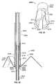
- FIG. 1is a downward perspective of an exemplary valve prosthesis system according to the present disclosure
- FIG. 2is a partially-sectional side view of an exemplary valve prosthesis system according to the present disclosure positioned relative to a heart annulus;
- FIG. 3Ais a side view of an exemplary prosthesis system according to the present disclosure, wherein an exemplary heart valve prosthesis is positioned within an exemplary delivery structure;
- FIG. 3Bis a partially-sectional side view of the exemplary prosthesis system of FIG. 3A , also shown positioned within the exemplary delivery structure;
- FIGS. 4A , 4 B, 4 C, 4 D, 4 E, 4 F, 4 G, 4 H, and 4 Iare schematic views illustrating percutaneous placement of a heart valve prosthesis relative to an annulus according to an exemplary embodiment of the present disclosure
- FIGS. 5 , 6 , and 7are schematic perspective views of variations of a positioning element according to the present disclosure.
- FIGS. 8 , 9 , 10 , 11 and 12are schematic side elevational and perspective views of variations of a prosthetic heart valve in accordance with the present disclosure
- FIGS. 13 and 14are respective side and views of a flexible ring according to the present disclosure.
- FIG. 15is a schematic side view of an exemplary valve prosthesis contained within a delivery catheter in accordance with the present disclosure
- FIGS. 16 , 17 , 18 , 19 and 20are sequential side views of an exemplary valve prosthesis being outwardly deployed from within a delivery catheter in accordance with the present invention
- FIG. 21is a schematic perspective view of a variation of a valve prosthesis system in accordance with the present disclosure.
- FIG. 22is a schematic perspective view of a folded/compressed valve prosthesis of the valve prosthesis system of FIG. 21 ;
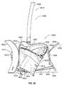
- FIG. 23is a side view of a deployed valve prosthesis of the valve prosthesis system of FIG. 21 ;
- FIG. 24is a cutaway detail view of the deployed valve prosthesis of FIG. 23 ;
- FIG. 25is a schematic perspective view of a folded/compressed valve prosthesis in accordance with the present disclosure.
- FIG. 26is a side view of a deployed valve prosthesis of the valve prosthesis system of FIG. 25 ;
- FIG. 27is a cutaway detail view of the deployed valve prosthesis of FIG. 26 ;
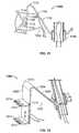
- FIG. 28is a schematic perspective view of a variation of a valve prosthesis system in accordance with the present invention.
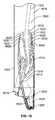
- FIG. 29is a side elevational view of a valve prosthesis of the valve prosthesis system of FIG. 28 ;
- FIG. 30is a perspective view of a cable guide tube of the valve prosthesis system of FIG. 28 ;
- FIG. 31is an end view of a valve prosthesis of the valve prosthesis system of FIG. 28 ;
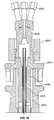
- FIG. 32is a sectional side view of a valve prosthesis of the valve prosthesis system of FIG. 28 taken along section line 32 - 32 appearing in FIG. 31 ;
- FIG. 33is a perspective view of a resilient element in the valve prosthesis illustrated in FIG. 32 ;
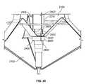
- FIG. 34is an end view of the valve prosthesis system of FIG. 28 ;
- FIG. 35is a sectional side view of a tool of the valve prosthesis system of FIG. 28 taken along section line 35 - 35 appearing in FIG. 34 ;
- FIG. 36is a sectional side view of part of the tool of the valve prosthesis system of FIG. 28 taken along section line 35 - 35 appearing in FIG. 35 ;
- FIG. 37is a sectional side view of another part of the tool of the valve prosthesis system of FIG. 28 taken along section line 35 - 35 appearing in FIG. 35 .
- valve prosthesis systems and deployment systems/methodsare provided according to the present disclosure.
- the disclosed systems and methodspermit surgeons/clinicians to improve heart valve function without invasive surgical intervention.
- the disclosed valve prosthesis systemspermit a heart valve prosthesis to be percutaneously delivered to a desired anatomical location. Once located in the desired anatomical region/locale, the disclosed valve prosthesis system facilitates secure and aligned placement of a heart valve prosthesis relative to a heart annulus.
- Percutaneous delivery of the disclosed heart valve prosthesis as disclosed hereinprovides for efficient and effective clinical placement of a heart valve prosthesis.
- the disclosed heart valve prosthesis and associated delivery techniquesoffer numerous clinical benefits, including enhanced valve function without the need to remove existing valve leaflets, an ability to effectively and efficiently deliver a valve prosthesis percutaneously, and an ability to position and reposition a valve prosthesis relative to an annulus to ensure proper orientation relative to anatomical features.
- the valve prosthesis system 100includes a heart valve prosthesis 102 and a delivery structure 104 .
- the valve prosthesis 102includes a flexible ring 106 .
- Mounted with respect to the flexible ring 106are a plurality of leaflet membranes 108 , a valve skirt 110 , and a resilient element 112 .
- the resilient element 112may include a hub 114 and a plurality of legs 116 , each of the legs 116 extending from the hub 114 (e.g., in a regular radial arrangement, as shown in FIG.
- valve prosthesis 102may further include a corresponding plurality of positioning elements 120 , each such positioning element 120 being attached to one of the legs 116 of the resilient element 112 .
- the valve prosthesis 102may include three (3) leaflet membranes 108 , each leaflet membrane 108 assuming an inwardly bowed orientation when mounted with respect to the flexible ring 106 . More or fewer of the leaflet membranes 108 may be employed without departing from the spirit or scope of the present disclosure, provided the desired blood flow functionality is achieved.
- the leaflet membranes 108may be fabricated from xenograft tissue, e.g., the valve leaflets may be fabricated from standard biologic or artificial prosthetic material, such as cryo- or chemically-preserved bovine pericardium or porcine heart valve tissue.
- Synthetic membrane materialsmay also be employed in the fabrication of the leaflet membranes 108 , e.g., fiber-reinforced matrix materials.
- the leaflet membranes 108may be secured with respect to the flexible ring 106 through conventional means, e.g., creation of an annulus and/or cuff that surrounds, in whole or in part, the flexible ring 106 such that each of the plurality of leaflet membranes 108 extends downwardly with respect to the flexible ring 106 .
- the valve skirt 110may extend to a full extent of the flexible ring 106 , e.g., to a full extent of the circumference of the flexible ring 106 .
- the valve skirt 110may be formed from a single, contiguous structure, or may be defined by a plurality of adjacent and/or overlapping elements that, together, extend along the circumference of flexible ring 106 .
- the valve skirt 110may be sutured with respect to the flexible ring 106 .
- a cuffmay be formed at an edge of the valve skirt 110 , such cuff being adapted to receive the flexible ring 106 therewithin.
- the cuffmay extend along the entire edge of the valve skirt 110 or may be defined at discrete intervals along the length of the valve skirt 110 , such that the valve skirt 110 is mounted with respect to the flexible ring 106 at spaced intervals.
- the valve skirt 110may be fabricated from a variety of substantially flexible and/or pliable materials, e.g., xenographic tissue or a synthetic material that is compatible with blood flow, e.g., a non-thrombogenic material.
- valve skirt 110 and the leaflet membranes 108may be fabricated as integral/contiguous structures, e.g., from a desired xenographic and/or synthetic material, and such integral/continuous structure may be advantageously mounted with respect to the flexible ring 106 such that the functionalities of both elements (i.e., leaflet membrane functionality and valve skirt functionality) are achieved.
- the thickness of the valve skirt 110may be substantially uniform from edge-to-edge or may vary along its length.
- the valve skirt 110would be thicker in a region thereof adjacent the flexible ring 106 and thinner in a region thereof relatively more distant from the flexible ring 106 , thereby enhancing the flexibility of the valve skirt 110 in the latter region to provide more effective sealing functionality relative to adjacent anatomical structures/tissue.
- the thicker region adjacent the flexible ring 106may serve to reduce the likelihood of the valve skirt 110 disengaging from the flexible ring 106 .
- valve skirt 110may extend in a single direction relative to the flexible ring 106 , i.e., downward, it is contemplated according to the present disclosure that the valve skirt 110 may extend both upwardly and downwardly relative to the flexible ring 106 .
- the attachment means for securing the valve skirt 110 relative to the flexible ring 106would not necessarily be located at an edge thereof. Rather, such attachment means, e.g., cuff(s) and/or suturing, may be positioned along an intermediate line/region of the valve skirt 110 .
- a first portion of the valve skirt 110would be free to extend above the flexible ring 106
- a second portion of the valve skirt 110would be free to extend below the flexible ring 106 .
- Both portions of the valve skirt 110i.e., the portions above and below the flexible ring 106 , would advantageously function to seal the valve prosthesis 102 relative to a patient's anatomy when the valve prosthesis 102 is deployed relative thereto, as described in greater detail below.
- a portion of the valve skirt 110 extending above the flexible ring 106may include a notch or discontinuity to accommodate structures associated with the positioning elements 120 , as described in greater detail below.
- the valve skirt 110may have a downward length that is effective to achieve a desired level of sealing relative to surrounding anatomical structures.
- the valve skirt 110may have a downward length of about five (5) millimeters to about fifteen (15) millimeters relative to the flexible ring 106 . Similar dimensions are contemplated for the upward extending portion of the valve skirt 110 in implementations wherein the valve skirt 110 extends both above and below the flexible ring 106 .
- valve skirt 110may be tacked or otherwise secured in at least some manner relative to the resilient element 112 (e.g., to one or more of the legs 116 of the resilient element 112 ). In an alternative embodiment, the valve skirt 110 may be positioned radially outward of the positioning elements 120 .
- the resilient element 112may include three (3) legs 116 mounted in a circumferentially-spaced manner with respect to the flexible ring 106 via the mounting elements 118 .
- Each leg 116may be configured or adapted to include or assume an arcuate shape or bend in the vicinity of the flexible ring 106 .
- the legs 116may be spaced by about 120° relative to each other, although an alternative number and/or spacing of the legs 116 may be employed without departing from the spirit or scope of the present disclosure.
- the mounting elements 118may be of any suitable shape, design, configuration, and/or attachment technique relative to the legs 116 to permit rotational and/or overturning motion of the legs 116 relative to the hub 114 , and/or relative to the flexible ring 106 .
- the mounting elements 118may be substantially C-shaped, and/or tube shaped.
- the mounting elements 118may, for example, be affixed to respective undersides of the legs 116 (e.g., within an arcuate or bent portion thereof) through an appropriate mounting technique, e.g., a tack weld.
- the mounting elements 118may overlay the valve skirt 110 to the extent that the valve skirt 110 is secured to the flexible ring 106 in such circumferential region. Further, the valve skirt 110 may be tacked, adhered or otherwise joined to the underside of one or more of the legs 116 where the same extend over the valve skirt 110 .
- each of the positioning elements 120may be shaped, configured, and/or otherwise adapted to engage tissue, and/or to position the valve prosthesis 102 relative to tissue.
- each positioning element 120may define an outer surface 122 , an inner surface 124 opposite the outer surface 122 , an upper arcuate region 126 , and a lower arcuate region 128 opposite the upper arcuate region 126 .
- Each of the positioning elements 120may be coupled (e.g., fixedly joined) to a corresponding leg 116 of the resilient element 112 , e.g., through a weld between the inner surface 124 of the positioning element 120 a corresponding outer surface of the leg 116 .
- the positioning elements 120may be dimensioned such that the upper arcuate regions 126 thereof extend above the flexible ring 106 (e.g., when the valve prosthesis 102 assumes the orientation depicted in FIG. 1 ).
- the upper and lower arcuate regions 126 , 128 of the positioning elements 120may be spaced by a distance that facilitates positioning of the valve prosthesis 102 relative to a heart annulus, as described in greater detail below.
- the upper and lower arcuate regions 126 , 128may be spaced by between about seven (7) millimeters and about twenty-five (25) millimeters.
- the positioning elements 120 and the legs 116may be fabricated from a material that permits at least some degree of flexibility/deformation (e.g., elastic deformation), such as stainless steel or Nitinol of an appropriate thickness/gauge. Other materials for the positioning elements 120 and/or the legs 116 are possible.
- the lower arcuate regions 128 of the positioning elements 120may include a pair of spaced apertures 130 , 132 .
- the delivery structure 104may include a plurality of filaments or cords 134 , each cord 134 being threaded through a positioning element 120 via the pair of spaced apertures 130 , 132 formed therein, such that separate lengths 136 of the cord 134 extend away from the apertures 130 , 132 and radially inwardly toward the hub 114 of the resilient element 112 . As may be more clearly seen in FIG.
- the hub 114 of the resilient element 112may include one or more lumen(s) 200 (e.g., a centrally-located lumen 200 ), the delivery structure 104 may include a delivery tube 202 having one or more corresponding lumens 204 (e.g., an axially located lumen), and the lengths 136 of the cords 134 may pass from the respective lower arcuate regions 128 of the positioning elements 120 toward the hub 114 , into and through the lumen 200 thereof, and into and through the lumen 204 of the delivery tube 202 .
- lumen(s) 200e.g., a centrally-located lumen 200
- the delivery structure 104may include a delivery tube 202 having one or more corresponding lumens 204 (e.g., an axially located lumen)
- the lengths 136 of the cords 134may pass from the respective lower arcuate regions 128 of the positioning elements 120 toward the hub 114 , into and through the lumen 200 thereof, and into and through the
- Such lengths 136 of the cords 134may facilitate deployment of the valve prosthesis 102 relative to an annulus and/or associated heart tissue.
- the delivery tube 202may be flexible, and the lumen or lumens 204 may accommodate passage of a plurality of lengths 136 of cords 134 .
- three (3) positioning elements 120are associated with the valve prosthesis 102 and each positioning element 120 interacts with a separate cord 134 .
- the respective lumen(s) 200 , 204 of the hub 114 and the delivery tube 200may be appropriately sized and/or of an appropriate number to accommodate least six (6) separate lengths 136 of cords 134 , based on the looping of each cord 134 through a pair of spaced apertures 130 , 132 formed at or near the respective lower arcuate regions 128 of the positioning elements 120 .
- the legs 116 of the resilient element 112may cooperate with the hub 114 thereof and/or with the flexible ring 106 to provide stability to the valve prosthesis 102 , e.g., during the deployment process, and/or during the useful life of the valve prosthesis 102 in situ.
- the structural interaction between the legs 116 and the flexible ring 106 , and/or between the legs 116 and the hub 114permits a surgeon/clinician to utilize the lengths 136 of the cords 134 and the delivery structure 104 to remotely operate the valve prosthesis 102 (e.g., to remotely move/rotate the legs 116 relative to the flexible ring 106 and/or relative to the hub 114 ).
- Each of the legs 116may, for example, include one or more joints along its respective length (e.g., one or more living hinges at or near a mid-point thereof) to facilitate collapse of valve prosthesis 102 for catheter-based delivery thereof.
- one or more such jointsmay store energy so as to facilitate the delivery of a spring force to expand the flexible ring 106 to a full diameter thereof (or at least a substantial fraction thereof), or assist in an otherwise substantially self-powered expansion thereof, upon deployment of the valve prosthesis 102 in situ.
- one or more such jointsmay further store energy so as to urge the positioning elements 120 radially outward (e.g., toward secure engagement with corresponding tissue, and/or radially outward from a compressed shape associated with intra-catheter delivery).
- three (3) legs 116may extend from the hub 114 , such that the resilient element 112 assumes a ‘tripod’-type shape for expanding and/or supporting the valve prosthesis 102 (e.g., helping the flexible ring 106 to assume and/or maintain a shape consistent with the intended function of the valve prosthesis 102 , and/or to urge the positioning elements 120 radially outward) during deployment and/or while implanted in situ.
- valve prosthesis 102 of the valve prosthesis system 100is depicted in alignment and engagement with an heart valve annulus “A” and a heart wall “W” of a patient.
- the valve prosthesis 102is further shown displacing heart valve leaflet structure “V” (e.g., the valve prosthesis 102 is implanted within the annulus A for purposes of providing the valve function for which the valve leaflet structure V is no longer well suited).
- the annulus Ais depicted in an enlarged and symmetric fashion for ease of description.
- the actual geometric and dimensional details of the relevant anatomical structuresare well known to persons skilled in the art. As shown in FIG.
- each of the upper arcuate regions 126 of the respective positioning elements 120may be positioned advantageously so as to engage a corresponding part of an upper portion of the annulus A. In this fashion, at least, the positioning elements 120 may be employed in cooperation with each other to align the valve prosthesis 102 relative to the annulus A. As also shown in FIG. 2 , each of the lower arcuate regions 128 may be positioned advantageously so as to engage a corresponding part of the wall W below the annulus A. In this fashion, at least, the positioning elements 120 may be employed in cooperation with each other to stabilize and secure the valve prosthesis 102 relative to the overall anatomical environment.
- valve prosthesis 102may deflect the lower arcuate regions 128 of the positioning elements 120 inward by pulling or otherwise manipulating or moving the respective lengths 136 of the cords 134 a sufficient extent radially inwardly and/or upwardly through the hub 114 and the delivery tube 202 to cause the lower arcuate regions 128 of the positioning elements 120 to disengage from the wall W.
- the surgeon/clinicianmay then reposition the structure of the valve prosthesis 102 relative to the overall anatomical environment by pulling, pushing, or otherwise manipulating or moving the delivery tube 202 to a desired extent with respect to the delivery catheter (not separately shown). Such manipulation may, for example, be translated to the valve prosthesis 102 via the hub 114 and the legs 116 of the resilient element 112 .
- Such manipulationmay, for example, be translated to the valve prosthesis 102 via the hub 114 and the legs 116 of the resilient element 112 .
- the surgeon/clinicianmay elect to pull the valve prosthesis 102 at least partially back upward, causing the lower arcuate regions 128 of the positioning elements to engage a corresponding part of a lower portion of the annulus A, and/or to engage the heart valve leaflet structure V, which in at least some instances results in the valve prosthesis 102 to be lodged and/or anchored in a particularly secure fashion within the annulus A.
- the surgeon/clinicianmay withdraw the cords 134 from the valve prosthesis 102 through the delivery tube 202 by pulling outward on one length 136 thereof to a sufficient extent while leaving the other length 136 loose.
- the surgeon/clinicianmay further withdraw the remainder of the delivery structure 104 from the valve prosthesis 102 by separating the delivery tube 202 from the hub 114 of the resilient element 112 .
- Means for disconnecting the delivery tube 202 from the hub 114may take a variety of forms, e.g., a screw thread arrangement at the end of the delivery tube 202 that may be disengaged from a corresponding socket associated with the hub 114 .
- connection and/or disconnection meansare possible, including bayonet lock mechanisms, detent engagement mechanisms, and the like, at least some of which are further described hereinbelow.
- Tissue-engaging featurese.g., barbs, tacks or the like, may be formed on, in, and/or through one or more tissue-engaging surfaces of the respective positioning elements 120 .
- tissue-engaging featuresmay be formed on the outer surface 122 of the positioning elements 120 , e.g., within the upper and/or lower arcuate regions 126 , 128 .
- surface treatments and/or adjunct structuresmay be associated with the positioning elements 120 to promote tissue in-growth, thereby further enhancing the stability/security of an implanted valve prosthesis according to the present disclosure.
- a biologic coating and/or a material or fabric that promotes tissue in-growthe.g., DACRONTM material, may be applied to a desired portion/region of the respective outer surfaces 122 of the positioning elements 120 .
- valve prostheses and valve prosthesis systems and methodshave applicability in a variety of anatomical regions, e.g., as a prosthesis for the mitral valve, aortic valve, pulmonary valve, or tricuspid valve.
- Embodiments of the disclosed valve prosthesishave particular applicability for mitral valve applications.
- the valve prosthesis system 100 and/or the valve prosthesis 102may be sized and dimensioned to accommodate such use by adapting the annular ring to fit in the requisite anatomical space, e.g., a mitral, aortic, pulmonary, or tricuspid valve opening of the heart.
- the heart valve prosthesis 102may assume a collapsed configuration within a lumen 300 of a catheter 302 .
- the positioning elements 120may be substantially inverted, e.g., rotated approximately 180° relative to the flexible ring 106 to which they are mounted and relative to the hub 114 of the resilient element 112 , as compared to the relative positions or orientations the positioning elements 120 may tend to occupy with respect to such structure (e.g., as shown in FIG. 1 ) when not being subjected to the application of opposing outside forces.
- the flexible ring 106may also be substantially deformed and the legs 116 of the resilient element 112 may be deflected so as to permit the valve prosthesis 102 to fit within the catheter 302 .
- the upper and lower arcuate regions 126 , 128 associated with the respective positioning elements 120may be inwardly directed toward the delivery tube 202 .
- the upper and lower arcuate portions 126 , 128 of the respective positioning elements 120may be associated with and/or terminate in respective tips 304 , 306 , and such tips 304 , 306 may feature cut-outs (not shown in FIGS.
- FIGS. 4A-4Ian exemplary sequence of steps for percutaneously delivering and positioning the disclosed valve prosthesis 102 in a desired anatomical location are schematically depicted.
- the valve prosthesis 102may be navigated to the desired anatomical location, e.g., adjacent a mitral valve, aortic valve, pulmonary valve, or tricuspid valve, within a delivery catheter 400 having a distal end 402 .
- the valve prosthesis 102may be delivered to the mitral valve cavity transseptally or by direct venous or arterial delivery to the aortic valve, pulmonary valve, or tricuspid valve cavities.
- the valve prosthesismay be navigated to a desired location using a guide wire (not shown) that cooperates with a corresponding guide wire lumen (not shown) formed in or otherwise present within the delivery catheter 400 .
- the valve prosthesis 102may be advanced through the delivery catheter 400 along an associated guide wire in a collapsed/inverted orientation (by being pushed, for example, by the delivery tube 202 ) to the implantation position (e.g., left atrium for mitral valve) where the valve prosthesis 102 is deployed adjacent the diseased valve for subsequent implantation therein.
- valve prosthesis 102may be pre-positioned within the delivery catheter 400 at or near the distal end 402 , and both the valve prosthesis 102 and the distal end 402 of the delivery catheter 400 may be so advanced in unison along an associated guide wire.
- the delivery tube 202may be extended relative to the delivery catheter 400 to push the valve prosthesis 102 outward of the catheter via a corresponding opening in the distal end 402 .
- resilient properties of several components of the valve prosthesis 102particularly the flexible ring 106 and the legs 116 of the resilient element 112 ( FIG. 2 ), may cause at least the flexible ring 106 to automatically resume its non-deformed/uncompressed shape (e.g., as seen in FIG. 4B as well as all later figures in the sequence of FIGS.
- valve prosthesis 102may tend eventually to fully relax, and assume a generally non-deformed orientation, wherein the positioning elements 120 are seen to have overturned or become inverted by rotating both outwardly and downwardly past the horizontal (e.g., so that the outer surfaces 122 thereof face generally outward again, and the upper and lower arcuate regions 126 , 128 thereof are, once again, outwardly directed).
- the valve skirt 110may be appropriately substantially downwardly oriented and positioned for performing an advantageous sealing function (e.g., as against valve prolapse) upon being positioned in a desired anatomical position.
- the surgeon/clinicianmay deflect the lower arcuate regions 128 of the positioning elements 120 inward by pulling the respective lengths 136 of the cords 134 ( FIG. 2 ) a sufficient extent radially inward toward, and/or upward through, the hub 114 ( FIG. 2 ) and the delivery tube 202 in such a way as to continue (see FIG. 4D ) an overturning or inverting motion of the positioning elements 120 relative to the flexible ring 106 and the hub 114 ( FIG. 2 ), progressing through sequential orientations as depicted in FIGS. 4D and 4E and arriving at the particularly notable orientation depicted in FIG.
- the surgeon/clinicianmay be permitted to accomplish such deflection of the positioning elements 120 by grasping or otherwise seizing respective proximal ends (not shown) of the lengths 136 of the plurality of cords 134 ( FIG. 2 ) disposed outside the delivery catheter 400 and outside the patient's body and pulling such ends outward of the delivery catheter 400 and the patient's body.
- Such withdrawal of the lengths 136 of the cords 134results in the lower arcuate regions 128 of the positioning elements 120 being pulled radially inwardly, e.g., to a point where the tips 306 of the lower arcuate regions 128 extend at least partially downwardly toward the diseased valve.
- such downwardly-directed and relatively more closely spaced lower arcuate regions 128may be utilized in the manner of a probe or ‘plow’ to deflect the patient's leaflet membranes (see, e.g., valve structure V in FIG. 2 ) and/or otherwise facilitate advancing the valve prosthesis 102 downward into the patient's diseased valve such that the valve prosthesis 102 is able to be positioned at an appropriate implantation elevation and an appropriate lateral position relative to the annulus A,
- the upper arcuate regions 126 of the respective positioning elements 120may be cooperatively adapted to be contained within a common plane, e.g., in the manner of a “top hat”, so as to facilitate positioning/alignment of the valve prosthesis 102 relative to the annulus A.
- the circumferentially interrupted aspect exhibited by of the valve prosthesis 102 and collectively defined by the positioning elements 120may facilitate both inversion of the positioning elements 120 during percutaneous introduction, and effective alignment and tissue engagement/stability upon final implantation and in situ valve function.
- the valve prosthesis 102may be generally aligned in a desirable fashion upon each of the plurality of upper arcuate regions 126 substantially engaging a corresponding part of the upper portion of the annulus A.
- the valve prosthesis 102may now be further positioned and/or spatially oriented relative to the annulus A in the manner desired by the surgeon/clinician, e.g., as viewed through conventional imaging instrumentation.
- the positioning elements 120and particularly, the upper arcuate regions 126 thereof
- the surgeon/clinicianmay begin to relax an accumulated degree of tension within the lengths 136 of the plurality of cords 134 ( FIG. 2 ), and thereby begin to allow a corresponding accumulation of energy/spring force contained in the legs 116 ( FIG. 2 ) of the resilient element 112 ( FIG.
- the lower arcuate regions 128may be allowed to rotate radially outward to an extent sufficient to permit the respective tips 306 thereof to contact and/or engage the cardiac tissue comprising the wall W. Having retracted to an extent sufficient to permit such tissue engagement, the legs 116 of the resilient element 112 and/or the positioning elements 120 may still retain sufficient energy/spring force to further cause the respective tips 306 to collectively press against and/or become substantially embedded in place with respect to the wall W.
- Such collective spring forcemay be sufficient to permit the lower arcuate regions 128 of the positioning elements 120 to offer a degree of resistance against vertically upward pullout or displacement of the valve prosthesis 102 , e.g., a degree of resistance at least comparable to a naturally strong degree of resistance against vertically downward displacement thereof offered by the upper arcuate elements 126 positioned across and/or against the annulus A.
- the cords 134may be withdrawn from the positioning elements 120 . Thereafter, the remainder of the delivery structure 104 may be disconnected and/or separated from the valve prosthesis 102 (e.g., the delivery tube 202 may be disconnected from the hub 114 ( FIG. 2 ), thereby leaving the valve prosthesis 102 in an appropriate position relative to the patient's diseased heart valve to serve as a functional replacement thereof.
- the positioning elements 120may serve to maintain the native leaflet membranes (see valve structure V in FIG. 2 ) in an open position, and each of the leaflet membranes 108 and the valve skirt 110 mounted with respect to the flexible ring 106 may function to ensure appropriate directional control of blood flow therethrough.
- the disclosed valve prosthesis and associated delivery structures/methodsoffer numerous advantages relative to existing systems.
- the positioning elements associated with the disclosed valve prosthesis valveinclude upper and lower arcuate regions that may advantageously function to engage the annulus as well as the wall of the ventricular chamber below the annulus, thereby securely aligning and stabilizing the valve prosthesis (e.g., in a re-deployable manner) relative thereto.
- the invertible and collapsible aspects of the valve prosthesismay facilitate efficient percutaneous delivery and in situ manipulation of the disclosed valve prosthesis system.
- the disclosed valve skirtmay enhance sealing functionality of the disclosed valve prosthesis when positioned in situ as compared to that which might otherwise be the case (e.g., without such a skirt and/or the annular sealing function provided thereby).
- the “top-hat” geometry and/or functionality of the upper arcuate regions of the positioning elementsmay advantageously function to accurately and securely position the valve prosthesis relative to an annulus and associated anatomical structures.
- the disclosed design and implantation methodologymay not require extensive surgery, and that the disclosed positioning elements may function to provide stable and well aligned implantation, central blood flow, and/or a stable platform for the leaflet membranes. Moreover, positioning may be more precise than with a balloon expandable device, such as a stent. Additionally, and also unlike a stent, the positioning may potentially be repeated (e.g., until the desired implantation position and/or orientation is achieved).
- the heart valve prosthesis described hereinmay also allow anchoring relative to the valve annulus in states of the diseased valve in which a stent may not encounter sufficient tissue to which to adhere (e.g., as is commonly the case with respect to mitral valve disease).
- the heart valve prosthesismay be placed squarely at the site of a diseased heart valve, as distinct from certain existing heart valve prosthesis implementations characterized by the use of stents configured for placement in the connecting blood vessels adjacent to and/or near the diseased heart valve, and, as such, are designed to be disposed in spaced relation therewith, whether during or after implantation, or during in situ operation.
- stentsconfigured for placement in the connecting blood vessels adjacent to and/or near the diseased heart valve, and, as such, are designed to be disposed in spaced relation therewith, whether during or after implantation, or during in situ operation.
- the positioning elements 120 of the present disclosuremay be implemented by one or more of a plurality of variations, including those depicted in FIGS. 5-7 . More particularly, a positioning element 500 depicted in FIG. 5 is one such variation of the positioning element 120 .
- the positioning element 500may include upper and lower arcuate regions 502 , 504 , an intermediate region 506 disposed therebetween, and an outer surface 508 .
- An array 510 of holes 512may be formed in the outer surface 508 in a vicinity of the intermediate region 506 to encourage in-growth of tissue, increasing positional and orientational stability in situ.
- a positioning element 600is another such variation of the positioning element 120 .
- the positioning element 600may include upper and lower arcuate regions 602 , 604 , an intermediate region 606 disposed therebetween, and an outer surface 608 .
- An array 610 of spikes or spurs 612may be provided, extending from the outer surface 608 in a vicinity of the intermediate region 606 to facilitate secure engagement of tissue, similarly increasing positional and orientational stability in situ.
- a positioning element 700 depicted in FIG. 7is yet another variation of the positioning element 120 .
- the positioning element 700may include upper and lower arcuate regions 702 , 704 , an intermediate region 706 disposed therebetween, and an outer surface 708 .
- An array 710 of holes 712may be formed in, and spikes or spurs 714 may be provided so as to extend from, the outer surface 708 in a vicinity of the intermediate region 706 to facilitate both in-growth of tissue and secure engagement of tissue, also increasing positional and orientational stability in situ. While the holes 512 and 712 and the spurs 612 and 714 are shown in FIGS. 5-7 as appearing in the respective intermediate regions 506 , 606 , 706 of the respective positioning elements 500 , 600 , 700 , such features may alternatively, and/or in addition, be positioned in one or both of the upper 502 , 602 , 702 and lower 504 , 604 , 704 arcuate regions thereof.
- a leg 802 of a resilient element 804may support the positioning element 800 , which may in turn include a lower arcuate region 806 having a tissue-engaging tip 808 that, in a retracted state of the lower arcuate region 806 , may be coiled or ‘rolled up’ so as to extend inward toward an intermediate region 810 of the positioning element and/or downward toward itself
- a deployment structure 812may include a cord 814 attached to the lower arcuate region 806 (e.g., near the tip 808 thereof) to uncoil the lower arcuate region 806 so as to permit the tip 808 to be redirected outward so as to be capable of engaging with a the cardiac tissue comprising a patient's heart wall (not shown).
- a surgeon/clinicianmay be permitted to pull outward on the cord 814 during positioning of the positioning element 800 , and once the tip 808 has begun to engage the cardiac tissue, to release the cord 814 , allowing an accumulated energy/spring force inherent in the lower arcuate region 806 (e.g., the same having a coil-spring configuration) to impinge with additional force upon the cardiac tissue.
- Multiple instances of the positioning element 800may be provided in a valve prosthesis 816 (not otherwise shown) such that at least some balancing of reaction forces can be achieved, and an upper arcuate region 818 of the positioning element 800 may have a similar coiled configuration (not separately shown) to that of the lower arcuate region 806 .
- the valve prosthesis 900may include a resilient element 902 having a leg 904 generally similar to the legs 116 associated with the above-described resilient element 112 .
- the leg 904may support a claw 906 having an upper jaw 908 , a lower jaw 910 , and a hinge 912 disposed between the upper and lower jaws 908 , 910 .
- the valve prosthesis 900may further include a torsional spring (not shown) for biasing the upper and lower jaws 908 , 910 of the claw 906 in favor of closure toward each other, and securely engaging the cardiac tissue of a patient's heart wall.
- a deployment structure 914may include a cord 916 attached to the upper and lower jaws 908 , 910 .
- a surgeon/clinicianmay be permitted to pull outward on the cord 916 to hold the claw 906 open during positioning of the claw 906 .
- the surgeon/clinicianmay be permitted to release the cord 916 , allowing the spring bias to act on the upper and lower jaws 908 , 910 and thereby allowing the claw 906 to affix itself to the cardiac tissue.
- Multiple instances (not shown) of the claw 906may be provided in the valve prosthesis 900 .
- valve prostheses 1000 , 1100 , and 1200shown partially and schematically in FIGS. 10 , 11 and 12 , respectively.
- the valve prosthesis 1000 of FIG. 10may include a resilient element 1002 having multiple instances of a leg 1004 extending from a hub 1006 .
- the leg 1004may itself be a spring, and may include at least two leaves 1008 joined at an arcuate or bend region 1010 .
- the valve prosthesis 1000may further include one or more engaging elements 1012 , each of which may include a plurality of prongs 1014 for piercing and/or otherwise invasively engaging cardiac tissue as appropriate to secure the valve prosthesis 1000 in place relative to a diseased heart valve, and/or relative to an annulus associated therewith.
- the engaging element 1012may be supported by one of the leaves 1008 of the leg 1004 , and the valve prosthesis 1000 may include a plurality of sets of two engaging elements 1012 (e.g., having two prongs 1014 each) as shown in FIG. 10 .
- the valve prosthesis 1100 of FIG. 11may include a resilient element 1102 having multiple instances of a leg 1104 extending from a hub 1106 .
- the leg 1104may itself be a spring, and may include at least two leaves 1108 joined at an arcuate or bend region 1110 .
- the valve prosthesis 1100may further include one or more engaging elements 1112 , each of which may include two arms 1114 extending outward from a common point of connection in a V shape.
- the valve prosthesis 1100may further include biasing springs (indicated schematically at reference numeral 1116 ) for urging the arms 1114 of the engaging elements 1112 together for purposes of closing the engaging element 1112 about an annulus associated with a patient's diseased heart valve.
- the engaging element 1112may be supported by one of the leaves 1108 of the leg 1104 , and the valve prosthesis 1100 may include a plurality of such engaging elements 1112 .
- the valve prosthesis 1200 of FIG. 12may include a resilient element 1202 having multiple instances of a leg 1204 extending from a hub 1206 .
- the leg 1204may itself be a spring, and includes at least two leaves 1208 joined at an arcuate or bend region 1210 .
- the valve prosthesis 1200may further include one or more engaging elements 1212 , each of which may include a plurality of teeth 1214 for engaging cardiac tissue as appropriate to secure the valve prosthesis 1200 relative to a diseased heart valve.
- the engaging element 1212may be directly affixed to one of the leaves 1208 of the leg 1204 (e.g., the valve prosthesis 1200 may include a plurality of engaging elements 1212 having two rows of teeth 1214 each as shown in FIG. 12 ).
- the engaging element 1212may be hinged at a central location between the two rows of teeth 1214 such that the engaging element 1212 may be movable to at least some degree relative to the leg 1204 . Accordingly, in at least some such embodiments, the engaging element 1212 may be utilized in the manner of a toothed claw otherwise structurally and functionally similar to the claw 906 described above with reference to FIG. 9 .
- a variation of the above-discussed flexible ring 106is embodied by a flexible ring 1300 illustrated in FIGS. 13 and 14 .
- the flexible ring 1300may be resilient such that it may tend (e.g., absent any substantial compressive forces) to expand outward to assume a three-dimensional shape (e.g., the three-dimensional shape shown FIG. 14 ), in which the flexible ring 1300 may have a not insubstantial vertical height, in addition to a characteristic lateral width or diameter. More particularly, the flexible ring 1300 may include multiple instances of a hoop segment 1302 .
- the hoop segments 1302may be contained within a common horizontal plane (e.g., upon the flexible ring 1300 being expanded out to its maximum width and height) wherein the hoop segments may be separated by and/or coupled via a corresponding number of instances of a coupling segment 1304 extending vertically relative to the common horizontal plane, constituting at least a portion of the height extent of the flexible ring 1300 .
- Each hoop segment 1302may further include a notch 1306 to facilitate secure coupling of one or more of a valve skirt similar to the above-described valve skirt 110 , at least one leaflet membrane similar to the above-described leaflet membranes 108 , and/or an associated annulus or cuff similar to that described above.
- such couplingmay be obtained via a knotted suture (not shown) at least partially lodged within the notch 1306 so as to restrict relative movement of the valve skirt, leaflet membrane, and/or cuff relative to and/or about a circumference of the flexible ring 1300 .
- Each of the coupling segments 1304may comprise a spring having two leaves 1308 joined at an arcuate or bend region 1310 , whereby the flexible ring 1300 may be particularly amenable to being radially compressed and/or to assume a compact shape suitable for compressing a corresponding valve prosthesis (not separately shown) of which the flexible ring 1300 is a part, and/or passing such a prosthesis through a narrow-gauge catheter (not shown).
- the flexible ring 1300may include intermittent breaks in its circumference in the plane of the hoop segments 1302 (e.g., associated with the coupling segments 1304 ), its geometry may further contribute to an elastic radial compressibility exhibited by the flexible ring 1300 .
- the bend regions 1310 of the coupling segments 1304may further serve as anchoring points functionally similar to the notches 1306 .
- such notches 1306may be used as anchoring points for securing, and/or limiting a length extent of, commisure seams (not shown in FIGS. 13-14 ; see, e.g., corresponding structure illustrated and described below with reference to FIGS. 16-20 ) formed between corresponding leaflet membranes (not shown) of a heart valve prosthesis (not shown) incorporating the flexible ring 1300 in accordance with embodiments of the present disclosure.
- valve prosthesis 1500illustrated in FIG. 15 .
- the resilient element 1502 of the valve prosthesis 1500may be structurally and functionally similar to the above-described resilient element 112 .
- the legs 1504 of the resilient element 1502may flex inwardly toward the delivery tube 202 .
- the legs 1504may be adapted to flex inwardly toward the delivery tube 202 in a manner that facilitates an enhanced degree of radial compression of the valve prosthesis 1500 .
- Such flexure of the legs 1504may further permit the valve prosthesis 1500 to pass along a lumen 1506 of a catheter 1508 exhibiting a smaller internal diameter than would otherwise be the case.
- a modified version of the valve prosthesis system 100 in accordance with the present disclosureis embodied by a valve prosthesis system 1600 illustrated in various stages of operation in FIGS. 16 , 17 , 18 , 19 , and 20 .
- the valve prosthesis system 1600may include a valve prosthesis 1602 that is a modified version of the valve prosthesis 102 including substantially all structural and functional features thereof, with at least some exceptions as discussed below.
- the valve prosthesis 1602may include a resilient element 1604 having multiple instances of a leg 1606 extending radially outward from a hub 1608 , and multiple instances of a leaflet membrane 1610 .
- Commissures 1612 between the leaflet membranes 1610may be partially closed, or at least limited in length via respective sutured seams 1614 formed between the leaflet membranes 1610 .
- the sutured seams 1614may extend from a flexible ring 1616 of the valve prosthesis 1602 , or from a location in spaced relation below the flexible ring 1616 (e.g., as in embodiments of the valve prosthesis (not specifically shown) in which each of the leaflet membranes 1610 forms a portion of a larger membrane structure of unitary construction), downward to a point coinciding with respective free ends or distal edges of the leaflet membranes 1610 .
- the valve prosthesis system 1600may further include a delivery structure 1618 that, in addition to having cables 1620 and a delivery tube 1622 structurally and functionally similar to corresponding aspects of the delivery structure 104 , further includes a tower 1624 extending downward from the hub 1608 .
- the tower 1624may at least participate in defining a central axis 1625 of the valve prosthesis system 1600 , and may further introduce an axial (e.g., vertical or lengthwise) separation between an elevation (e.g., generally indicated at 1626 in FIG. 20 ) at which the legs 1606 meet the hub 1608 and an elevation (e.g., generally indicated at 1628 in FIG. 20 ) at which the cables 1620 extend, and/or are deployed, outward from the central axis 1625 .
- an elevatione.g., generally indicated at 1626 in FIG. 20
- an elevatione.g., generally indicated at 1628 in FIG. 20
- such an arrangementmay have the advantage of displacing and/or routing the cables 1620 generally away from an elevation (e.g., generally shown at 1630 in FIG.
- such an arrangementmay advantageously reduce and/or eliminate a risk of the cables 1620 abrading or cutting the leaflet membranes 1610 and/or the sutures of the sutured seams 1614 during a process of deploying, adjusting a position of, and/or otherwise implanting the valve prosthesis 1602 .
- a riskdoes not necessarily exist with respect to any particular embodiment of a heart valve prosthesis in accordance with the present embodiment.
- the use of a tower 1624 , or of another component structurally and/or functionally similar thereto, to introduce an appropriate axial separation between the cables 1620 and the leaflet membranes 1610 , and/or between the cables 1620 and the sutured seams 1614may provide a particular advantage.
- such an arrangementmay further permit additional energy and/or spring force to be built up within the resilient element 1604 by imparting significant flexure to the resilient element 1604 where the legs 1608 meet the hub 1606 .
- a sufficient amount of flexuremay be imparted thereby to the resilient element 1604 to cause the hub 1606 to be raised to an elevation substantially entirely above those of the respective positioning elements 1632 during a corresponding process of deployment from a catheter 1634 , in which the positioning elements 1632 may be overturned or inverted relative to the flexible ring 1616 and the hub 1608 in preparation for placement of the valve prosthesis 1602 with respect to a patient's diseased heart valve.
- Such elevated placement of the hub 1608 relative to the positioning elements 1632may further persist in the final in situ configuration of the valve prosthesis 1602 within the diseased heart valve (not specifically shown), such that an elevation of the hub 1608 may be and/or remain even with or above that of the corresponding annulus A (see FIG. 2 for comparison).
- the legs 1608may assume a final configuration relative to the hub 1606 such that: i) the legs 1608 either effectively no longer extend vertically upward from the hub 1608 ; or ii) an extent to which the legs 1608 continues to so extend upward from the hub 1606 is substantially reduced; and/or iii), the legs 1608 have substantially completely been overturned relative to the flexible ring 1616 so as to extend substantially completely downwardly from the hub 1608 . Any one or all of these arrangements of the legs 1608 of the resilient element 1604 relative to the hub 1606 thereof and/or relative to the flexible ring 1616 may have the advantageous effect of reducing an occurrence of or an extent of eddies or turbulence in the flow of blood past or through the resilient element 1604 .
- an extent and/or magnitude of a shear force characteristic of the flow of blood through the heart valve prosthesis 1602may be beneficially adjusted, limited, and/or reduced.
- a variation of the valve prosthesis system 100is embodied by a valve prosthesis system 2100 illustrated in FIG. 21 .
- the valve prosthesis system 2100may include a valve prosthesis 2102 and a delivery structure 2104 .
- the valve prosthesis 2102may be a variation of the above-discussed valve prosthesis 102
- the delivery structure 2104may be a variation of the above-discussed delivery structure 104 .
- the delivery structure 2104may include an outer catheter 2106 , a guide wire 2108 , and a tool 2110 for allowing a surgeon/clinician to move the valve prosthesis 2102 within and relative to the outer catheter 2106 along the guide wire 2108 .
- the valve prosthesis 2102is shown twice in FIG.
- valve prosthesis 2102is shown in the folded/compressed configuration shown in FIG. 21 for movement within the outer catheter 2106 along the guide wire 2108 .
- the valve prosthesis 2102may include a sleeve 2200 extending downward to at least some extent from a hub 2202 of a resilient element 2204 .
- the delivery structure 2104may further include a cable guide tube 2206 for accommodating the guide wire 2108 and a set of deployment cables 2208 , and a delivery tube 2210 including a central lumen 2212 .
- the delivery structure 2104may still further include a fitting 2214 .
- the fitting 2214may extend entirely through the hub 2202 and the sleeve 2200 such that at least an upper portion 2216 of the fitting 2214 is disposed above the hub 2202 , and at least a lower portion 2218 of the fitting 2214 is disposed below the sleeve 2200 .
- the fitting 2214may include a central lumen 2220 via which the guide wire 2108 and the deployment cables 2208 may pass through the fitting 2214 (and, thereby, through the hub 2202 ).
- the upper portion 2216 of the fitting 2214may be sized and shaped (e.g., via external circumferential ribs 2222 ) for press-fit insertion within the central lumen 2212 of the delivery tube 2210 , and/or to receive a corresponding end of the cable guide tube 2206 for press-fit termination thereof within the central lumen 2220 .
- the lower portion 2218 of the fitting 2214may form a tower 2224 .
- the tower 2224may be a variation of the above-described tower 1624 ( FIG. 16 ).
- the delivery tube 2210 and the fitting 2214may be keyed to each other to prevent relative rotation therebetween.
- an end of the delivery tube 2210 adjacent the hub 2202may include one or more slots 2226
- the fitting 2214may include one or more complementary radially-protruding tabs (not separately shown) to mate with the slots 2226 upon the fitting 2214 being press-fit within the central lumen 2212 of the delivery tube 2210 .
- Other anti-rotation solutions and/or featuresare possible.
- the cable guide tube 2200may have multiple components, including an internal length of metal tubing 2228 , and an external length of shroud-type tubing 2230 .
- the internal length of metal tubingmay be thin-walled and braided for stiffness and/or resistance to kinking.
- the external length of shroud-type tubingmay be sized, shaped and configured to facilitate formation of a press-fit termination within the central lumen 2220 of the fitting 2214 .
- valve prosthesis 2102is shown after having emerged from the discharging end 2114 of the outer catheter 2106 , and after the surgeon/clinician has permitted the positioning elements 2300 to overturn relative to a flexible ring 2302 and/or relative to the hub 2202 (e.g., via an internally-generated spring force), and/or has utilized the tool 2110 ( FIG. 21 ) and the cables 2208 to cause or assist in causing the positioning elements 2300 to overturn relative thereto.
- the tool 2110FIG. 21
- the cables 2208to cause or assist in causing the positioning elements 2300 to overturn relative thereto.
- the tower 2224may beneficially extend a point of radial distribution of the cables 2208 axially downward to an elevation below that at which a plurality of legs 2302 of the resilient element 2204 meet the hub 2202 thereof.
- the sleeve 2200which may be funnel-shaped and swaged to the hub 2202 , may facilitate this function by providing lateral support to the cable deployment tower 2224 .
- the delivery structure 2104may further include one or more additional cables 2400 .
- the cables 2400may function to axially secure the delivery tube 2210 to the hub 2202 , and/or to the sleeve 2200 , until such time as the valve prosthesis 2102 is determined to be properly positioned and oriented relative to the patient's diseased heart valve. More particularly, each instance of a cable 2400 may form a corresponding loop around a portion of the sleeve 2200 , and include lengths 2402 passing upward therefrom. For example, one such length 2402 may pass through the central lumen 2212 ( FIG.
- Such cables 2400may further be withdrawn from the delivery structure 2104 when no longer needed (e.g., upon the valve prosthesis 2102 being determined to be properly positioned and oriented relative to the patient's diseased heart valve).
- the delivery tube 2210 and the hub 2202may now no longer axially secured to each other, and the fitting 2214 and the delivery tube 2210 may remain axially secured to each other.
- the surgeon/clinicianmay elect to withdraw the delivery tube 2210 from the patient's body via the outer catheter 2106 ( FIG.
- the surgeon/clinicianmay, by pulling upward on the delivery tube 2210 , further withdraw the tower 2224 upward from and out of the hub 2202 .
- the sleeve 2200may travel outward of the patient's body along with the delivery tube 2210 .
- the valve prosthesis system 2500may include a valve prosthesis 2502 and a delivery structure 2504 .
- the valve prosthesis 2502may be a variation of the above-discussed valve prosthesis 102
- the delivery structure 2504may be a variation of the above-discussed delivery structure 104 .
- the delivery structure 2504may include an outer catheter 2506 and a guide wire 2508 for allowing a surgeon/clinician to move the valve prosthesis 2502 within and relative to the outer catheter 2506 via an appropriate tool (e.g., tool 2110 of FIG. 1 ) along the guide wire 2508 .
- the valve prosthesis 2502is shown in a folded/compressed configuration for movement within the outer catheter 2506 along the guide wire 2508 .
- the delivery structure 2504may further include a set of deployment cables 2510 , a delivery tube 2512 including a central lumen 2514 , and a fitting 2516 .
- the fitting 2516may extend entirely through a hub 2518 of a resilient element 2520 of the valve prosthesis 2502 such that at least an upper portion 2522 of the fitting 2516 is disposed above the hub 2518 , and at least a lower portion 2524 of the fitting 2516 is disposed below the hub 2518 .
- the fitting 2516may include a central lumen 2526 via which the guide wire 2508 and the deployment cables 2510 may pass through the fitting 2516 (and, thereby, through the hub 2518 ).
- the upper portion 2522 of the fitting 2516may be sized and shaped (e.g., via external circumferential ribs 2528 ) for press-fit insertion within the central lumen 2514 of the delivery tube 2512 .
- the lower portion 2524 of the fitting 2516may form a tower 2530 .
- the tower 2530may be a variation of the above-described tower 1624 ( FIG. 16 ).
- the valve prosthesis 2502is shown after having emerged from the outer catheter 2506 ( FIG. 22 ), and after the surgeon/clinician has permitted the positioning elements 2600 to overturn relative to a flexible ring 2602 and/or relative to the hub 2518 (e.g., via an internally-generated spring force), and/or has utilized an appropriate tool (e.g., tool 2110 of FIG. 21 ) and the cables 2510 to cause the positioning elements 2600 to overturn or invert relative thereto.
- the tower 2530may beneficially extend a point of radial distribution of the cables 2510 axially downward to an elevation below that at which a plurality of legs 2604 of the resilient element 2520 meet the hub 2518 thereof.
- the fitting 2516may further includes multiple instances of an outwardly-biased, inwardly deflectable finger 2700 extending from a point on the cable deployment tower 2530 below the hub 2518 , through a corresponding cutout in the hub 2518 , and upward to a point on the fitting 2516 above the hub 2518 .
- an outwardly-biased, inwardly deflectable finger 2700extending from a point on the cable deployment tower 2530 below the hub 2518 , through a corresponding cutout in the hub 2518 , and upward to a point on the fitting 2516 above the hub 2518 .
- corresponding interlocking features(not separately shown) formed in the hub 2518 and the fingers 2700 may cooperate to secure the valve prosthesis 2502 axially relative to the fitting 2516 .
- Each such finger 2700may be further deflectable radially inwardly into an accommodating cavity 2702 formed in the fitting 2516 .
- the delivery structure 2504may further include a collar 2704 that may be disposed around the fitting 2516 between each such finger 2700 and its corresponding cavity 2702 , such that whenever the collar 2704 is so positioned, the finger 2700 may be prevented from being deflected into its corresponding cavity 2702 .
- the delivery structure 2504may still further include one or more cables 2706 forming a corresponding loop around each such finger 2700 so as to be useable to pull or retract each such finger 2700 into its corresponding cavity 2702 in the absence of the collar 2704 .
- the delivery structure 2504may yet further include one or more cables 2708 forming corresponding loops around a flange 2710 of the collar 2704 so as to be useable to pull the collar 2704 upward and away from the fingers 2700 such that the collar 2704 ceases to block inward deflection of the fingers 2700 . Accordingly, upon the valve prosthesis 2502 being determined to be properly positioned and oriented relative to the patient's diseased heart valve, a surgeon/clinician may pull or otherwise manipulate the cables 2708 to displace the collar 2704 upward and away from the fingers 2700 , and pull or otherwise manipulate the cables 2706 to deflect the fingers 2700 inward toward the cavities 2702 , and out of engagement with the hub 2518 .
- the hub 2518 and the fitting 2516may now no longer being axially secured relative to each other, and the fitting 2516 and the delivery tube 2512 ( FIG. 25 ) may remain axially secured relative to each other.
- the surgeon/clinicianmay elect to withdraw each of the fitting 2516 and the delivery tube 2512 from the patient's body via the outer catheter 2506 by pulling upward on the delivery tube 2512 .
- the tower 2530may be part of the fitting 2516
- the surgeon/clinicianmay, by pulling upward on the delivery tube 2512 , withdraw the tower 2530 upward from and outward of the hub 2518 .
- valve prosthesis system 2800may include a valve prosthesis 2802 and a delivery structure 2804 .
- the valve prosthesis 2802may be a variation of the above-discussed valve prosthesis 102
- the delivery structure 2804may be a variation of the above-discussed delivery structure 104 .
- the delivery structure 2804may include a release tube 2806 having a distal end 2808 adjacent the valve prosthesis 2802 , a locking sleeve 2810 positioned adjacent the valve prosthesis 2802 and coupled to the release tube 2806 at the distal end 2808 thereof, and a tower 2812 extending through and beyond the valve prosthesis 2802 .
- the tower 2818may be a variation of the above-discussed tower 1624 .
- the delivery structure 2804may further include a tool 2814 .
- the tool 2814may be configured to permit and/or facilitate a surgeon/clinician, among other functions described in more detail hereinafter, to move the valve prosthesis 2802 within and relative to an outer catheter (not shown) along a guide wire (not shown), to deliver and/or deploy the valve prosthesis 2802 adjacent a patient's diseased heart valve, to position the deployed valve prosthesis 2802 relative to such heart valve before and during a prosthesis implantation procedure, and/or to cause the valve prosthesis 2802 to be released after deployment and positioning thereof in situ., allowing the valve prosthesis 2802 to remain in place and the delivery structure 2804 to be entirely withdrawn from the patient's body.
- the tool 2814may include a body 2816 having a proximal end 2818 directed away from the patient and a distal end 2820 directed toward the patient, a gripping handle 2822 disposed between the proximal end 2818 and the distal end 2820 , a prosthesis manipulation mechanism 2824 mounted with respect to the body 2816 at the proximal end 2818 thereof, and a prosthesis release mechanism 2826 mounted with respect to the body 2816 at the distal end 2820 thereof.
- the prosthesis deployment mechanism 2824may include an actuation arm 2828 movably mounted the body 2816 , a cable mount 2830 , and an attachment fitting 2832 for attaching the cable mount 2830 to the actuation arm 2828 for movement therewith relative to the body 2816 .
- the cable mount 2830may include a port 2834 for receiving and/or discharging a guide wire (not shown), and multiple instances of an attachment fitting 2836 for attaching a respective cable (not shown) to the cable mount 2830 for movement therewith relative to the body 2816 .
- the prosthesis release mechanism 2826may include an attachment fitting 2838 for attaching the release tube 2806 to the tool 2814 , and an actuation wheel 2840 movably mounted to the body 2816 for moving the release tube 2806 and the locking sleeve 2810 relative to the body 2816 , and/or relative to the valve prosthesis 2802 .
- the valve prosthesis 2802may include a hub 2900 and a resilient element 2902 coupled to the hub 2900 .
- the resilient element 2902may include a hub flange 2904 at which the resilient element 2902 may be coupled to the hub 2900 and multiple instances of a leg 2906 that may extend radially outward from the hub flange 2904 .
- One or more of the multiple instances of a leg 2906may be of unitary construction with the hub flange 2904 .
- the valve prosthesis 2802is shown after having emerged from an outer catheter (not shown), and after the surgeon/clinician has utilized the tool 2814 ( FIG.
- the delivery structure 2804includes a cable guide tube 2908 disposed within the release tube 2806 . As shown in FIGS.
- the cable guide tube 2908includes an interior wall 3000 defining a central lumen 3002 , an exterior wall 3004 defining an outer surface 3006 and, with a series of radially-extending interior walls 3008 , defining multiple instances of a peripheral lumen 3010 arranged in a regular pattern around the central lumen 3002 .
- the hub 2900 of the valve prosthesis 2802includes a body 3200 including a wall 3202 .
- the wall 3202is cylindrical in shape so as to define a central lumen 3204 passing through the body 3200 , the central lumen 3204 being sized and shaped so as to receive and accommodate the cable deployment tower 2812 .
- Each of the hub 2900 and the cable deployment tower 2812may be fabricated from stainless steel, and the inner diameter of the central lumen 3204 of the hub 2900 and the outer diameter of the cable deployment tower 2812 may be controlled relative to each other such that a relatively precise lateral fit exists between the two parts while also permitting relatively free movement of the cable deployment tower 2812 in the axial direction relative to the hub 2900 for purposes of pulling the cable deployment tower 2812 free of the valve prosthesis 2802 upon the latter being implanted within a patient's diseased heart valve (not shown) (e.g., wherein the only available reaction force is that which is provided by the cardiac tissue with which the valve prosthesis 2802 is engaged).
- the wall 3202 of the hub 2900extends axially to define the central lumen 3204 .
- an annular ledge 3206extends outward from the wall 3202 .
- the hub flange 2904 of the resilient element 2902attaches to the hub 2900 at the circumferential skirt 3206 .
- the body 3200further includes a coupling interface 3208 .
- the coupling interface 3208includes an annular protrusion 3210 extending outward from the wall 3202 , which as shown in FIG. 32 , may be have a rounded profile.
- the delivery structure 2804further includes a guide wire sleeve 3212 , a fitting 3214 , and a resilient element 3216 .
- the guide wire sleeve 3212is disposed within the cable deployment tower 2812 .
- the fitting 3214joins, within the release tube 2806 , the cable guide tube 2908 (on one side of the fitting 3214 ) with the cable deployment tower 2812 and the guide wire sleeve 3212 (on an opposite side of the fitting 3214 ).
- the resilient element 3216includes a distal end 3300 that includes a collar 3302 that at least partially defines a central lumen 3304 through the resilient element 3216 , and a proximal end 3306 featuring a coupling interface 3308 .
- the coupling interface 3308is peripherally segmented and includes multiple instances of an outwardly biased and inwardly deflectable spring finger 3310 .
- Each such spring finger 3310includes a depression 3312 having a segmented annular shape and sectional profile to match that of the annular protrusion 3210 ( FIG. 32 ) of the coupling interface 3208 of the hub 2900 .
- the resilient element 3216may be affixed to the cable deployment tower 2812 such that the latter is lodged within the central lumen 3304 of the former.
- the locking sleeve 2810includes an axially narrowed distal end 3218 near which the locking sleeve 2810 is lodged within the proximal end 2808 of the release tube 2806 , and an axially expanded proximal end 3220 extending toward the valve prosthesis 2802 .
- the proximal end 3220 of the locking sleeve 2810is of a large enough interior diameter to surround and extend over the proximal end 3306 ( FIG. 33 ) of the resilient element 3216 .
- the relative dimensions of the resilient element 3216 and the locking sleeve 2810are such that the locking sleeve 2810 is capable of deflecting the spring fingers 3310 ( FIG. 33 ) of the resilient element 3216 inward. If at this time the coupling interface 3308 ( FIG. 33 ) of the resilient element 3216 and the coupling interface 3208 of the hub 2900 overlap each other (e.g., axially), the hub 2900 and the resilient element 3216 will become axially coupled, and may be moved axially within an outside catheter (not shown) together as a unit.
- valve prosthesis 2802upon the valve prosthesis 2802 being properly positioned and oriented with respect to a patient's diseased heart valve, such an arrangement enables a surgeon/clinician to release the valve prosthesis 2802 by causing the release tube 2806 to retract away from the valve prosthesis 2802 and the resilient element 3216 such that the spring fingers 3310 deflect radially outward and lose their grip on the annular protrusion 3210 of the hub 2900 .
- the cable deployment tower 2812can be smoothly withdrawn from within the hub 2900 , and the delivery structure 2804 completely withdrawn from the patient via the external catheter (not shown).
- the tool 2814includes a central lumen 3500 extending through an entire axial length of the tool 2814 .
- the central lumen 3500is adapted to accommodate, at least, a guide wire (not shown).
- the body 2816 of the tool 2814includes a central cavity 3600 , and the actuation arm 2828 of the prosthesis deployment mechanism 2824 is disposed within and moves relative to the central cavity 3600 .
- Cables (not shown) passing through the actuation arm 2828may pass into the cable mount 2830 and extend into one or more passages in communication therewith and terminating in an attachment fitting 2832 , at which the cable (not shown) may be axially secured to the cable mount 2830 , and by extension, to the actuation arm 2828 .
- up to six separate cablesmay be so accommodated and axially coupled to the cable mount 2830 .
- Other numbers of cables accommodated by a cable mount with more or fewer attachment fittingsare possible.
- the cable guide tube 2908may extend through the tool 2814 , e.g., at least to an extent of the prosthesis deployment mechanism 2824 . In at least some circumstances in accordance with embodiments of the present disclosure, a surgeon/clinician may not necessarily require the cable guide tube 2908 to be or remain axially fixed with respect to the tool 2814 .
- the tool 2814may include no particular securing mechanism with respect to the cable guide tube 2908 , in which case a proximal end of the cable guide tube 2908 may extend into the tool 2814 , wherein neither the proximal end nor or any other portion of the cable guide tube 2908 will necessarily be lodged in a corresponding fitting, or terminated in any particular way, facilitating axial relative motion between the cable guide tube 2908 and the tool 2814 .
- a surgeon/clinicianrequiring the cable guide tube 2908 to at least temporarily be or remain axially fixed with respect to the tool 2814 .
- the surgeon/clinicianmay rely on an overall or locally substantial static or dynamic friction within the delivery structure 2804 (e.g., between the cable guide tube 2908 and other portions of the delivery structure 2804 , such as the release tube 2806 ).
- the tool 2814may further include a clamp or fitting (not shown) or other similar mechanism or securing means to at least temporarily secure (e.g., axially fix) the cable guide tube 2908 with respect to the tool 2814 , e.g., with respect to the body 2816 of the tool 2814 , and/or to the prosthesis deployment mechanism 2824 thereof.
- Other configurationsare possible.
- a surgeon/clinicianmay grasp the gripping handle 2822 with one hand, grasp the actuation arm 2828 with the other hand, and pull the actuation arm 2828 outward of the body 2816 to move the cables outward of the valve prosthesis 2802 to cause the valve prosthesis to assume the proper shape for insertion into the valve (e.g., see, e.g., FIGS. 4F and 20 ).
- the actuation arm 2828may be rotated relative to the body 2830 to engage a catch (not separately shown) that preserves the existing axial positions of the actuation arm 2828 and the body 2830 relative to each other, enabling the surgeon/clinician to focus on proper placement of the valve prosthesis 2802 relative to the diseased valve without being concerned that the valve prosthesis 2802 will abruptly revert to a previously held shape or assume any other shape that is not intended.
- the prosthesis release mechanism 2826may further include an attachment sleeve 3700 that is spring biased outward of the proximal end 2820 of the tool 2814 but is moveable axially relative to the body 2816 .
- the attachment sleeve 3700receives the release tube 2806 and the attachment fitting 2838 , wherein the attachment fitting 2838 cooperates with the attachment sleeve 3700 to axially secure a distal end 3702 of the release tube 2806 relative to the attachment sleeve 3700 .
- the prosthesis release mechanism 2826further includes one or more anti-rotation pins 3704 emerging from the attachment sleeve 3700 and interacting with an axially-extending channel 3706 formed in the body 2816 of the tool 2814 so as to prevent rotation of the attachment sleeve 3700 relative to the body 2816 but permit the attachment sleeve 3700 to translate axially relative thereto.
- the actuation wheel 2840may be coupled to the body 2816 of the tool 2814 via screw threads and may be adapted to contact the pins 3704 and urge the pins 3704 axially inward relative to the body 2816 . This may cause the release tube 2806 to retract away from the valve prosthesis 2802 , such that the resilient element 3216 ( FIG.
- the delivery structure 2804may be withdrawn from the patient, leaving the valve prosthesis 2802 in place relative to the diseased heart valve.
Landscapes
- Health & Medical Sciences (AREA)
- Cardiology (AREA)
- Engineering & Computer Science (AREA)
- Biomedical Technology (AREA)
- Heart & Thoracic Surgery (AREA)
- Transplantation (AREA)
- Oral & Maxillofacial Surgery (AREA)
- Vascular Medicine (AREA)
- Life Sciences & Earth Sciences (AREA)
- Animal Behavior & Ethology (AREA)
- General Health & Medical Sciences (AREA)
- Public Health (AREA)
- Veterinary Medicine (AREA)
- Prostheses (AREA)
- Surgical Instruments (AREA)
Abstract
Description
Claims (40)
Priority Applications (21)
| Application Number | Priority Date | Filing Date | Title |
|---|---|---|---|
| US11/869,972US7753949B2 (en) | 2007-02-23 | 2007-10-10 | Valve prosthesis systems and methods |
| US11/870,001US20080208328A1 (en) | 2007-02-23 | 2007-10-10 | Systems and Methods For Placement of Valve Prosthesis System |
| JP2009550947AJP2010518976A (en) | 2007-02-23 | 2008-01-03 | Artificial valve system and method |
| AU2008218947AAU2008218947B2 (en) | 2007-02-23 | 2008-01-03 | Valve prosthesis systems and methods |
| EP08713452.4AEP2114305B1 (en) | 2007-02-23 | 2008-01-03 | Valve prosthesis systems and methods |
| EP08713462AEP2114306A2 (en) | 2007-02-23 | 2008-01-03 | Systems and methods for placement of valve phosthesis system |
| CA2678970ACA2678970C (en) | 2007-02-23 | 2008-01-03 | Valve prosthesis systems and methods |
| PCT/US2008/050096WO2008103497A2 (en) | 2007-02-23 | 2008-01-03 | Valve prosthesis systems and methods |
| CA002678971ACA2678971A1 (en) | 2007-02-23 | 2008-01-03 | Systems and methods for placement of valve prosthesis system |
| AU2008218948AAU2008218948A1 (en) | 2007-02-23 | 2008-01-03 | Systems and methods for placement of valve prosthesis system |
| PCT/US2008/050113WO2008103498A2 (en) | 2007-02-23 | 2008-01-03 | Systems and methods for placement of valve phosthesis system |
| JP2009550948AJP2010518977A (en) | 2007-02-23 | 2008-01-03 | Artificial valve system placement system and method |
| US12/028,572US8070802B2 (en) | 2007-02-23 | 2008-02-08 | Mitral valve system |
| CA002678940ACA2678940A1 (en) | 2007-02-23 | 2008-02-20 | Mitral valve system |
| PCT/US2008/054410WO2008103722A2 (en) | 2007-02-23 | 2008-02-20 | Mitral valve system |
| JP2009550619AJP2010518947A (en) | 2007-02-23 | 2008-02-20 | Mitral valve system |
| AU2008218700AAU2008218700A1 (en) | 2007-02-23 | 2008-02-20 | Mitral valve system |
| EP08730251AEP2124827A2 (en) | 2007-02-23 | 2008-02-20 | Mitral valve system |
| IL200430AIL200430A0 (en) | 2007-02-23 | 2009-08-17 | Valve prosthesis systems and methods |
| IL200475AIL200475A0 (en) | 2007-02-23 | 2009-08-18 | Mitral valve system |
| IL200474AIL200474A0 (en) | 2007-02-23 | 2009-08-18 | Systems and methods for placement of valve prosthesis system |
Applications Claiming Priority (2)
| Application Number | Priority Date | Filing Date | Title |
|---|---|---|---|
| US90298807P | 2007-02-23 | 2007-02-23 | |
| US11/869,972US7753949B2 (en) | 2007-02-23 | 2007-10-10 | Valve prosthesis systems and methods |
Related Child Applications (1)
| Application Number | Title | Priority Date | Filing Date |
|---|---|---|---|
| US12/028,572Continuation-In-PartUS8070802B2 (en) | 2007-02-23 | 2008-02-08 | Mitral valve system |
Publications (2)
| Publication Number | Publication Date |
|---|---|
| US20080208332A1 US20080208332A1 (en) | 2008-08-28 |
| US7753949B2true US7753949B2 (en) | 2010-07-13 |
Family
ID=39710690
Family Applications (2)
| Application Number | Title | Priority Date | Filing Date |
|---|---|---|---|
| US11/869,972Active2028-02-27US7753949B2 (en) | 2007-02-23 | 2007-10-10 | Valve prosthesis systems and methods |
| US11/870,001AbandonedUS20080208328A1 (en) | 2007-02-23 | 2007-10-10 | Systems and Methods For Placement of Valve Prosthesis System |
Family Applications After (1)
| Application Number | Title | Priority Date | Filing Date |
|---|---|---|---|
| US11/870,001AbandonedUS20080208328A1 (en) | 2007-02-23 | 2007-10-10 | Systems and Methods For Placement of Valve Prosthesis System |
Country Status (7)
| Country | Link |
|---|---|
| US (2) | US7753949B2 (en) |
| EP (2) | EP2114305B1 (en) |
| JP (2) | JP2010518977A (en) |
| AU (2) | AU2008218947B2 (en) |
| CA (2) | CA2678971A1 (en) |
| IL (2) | IL200430A0 (en) |
| WO (2) | WO2008103497A2 (en) |
Cited By (153)
| Publication number | Priority date | Publication date | Assignee | Title |
|---|---|---|---|---|
| US20050216079A1 (en)* | 2000-09-20 | 2005-09-29 | Ample Medical, Inc. | Heart valve annulus device and method of using same |
| US20070093890A1 (en)* | 2005-10-26 | 2007-04-26 | Eliasen Kenneth A | Heart valve implant |
| US20100022948A1 (en)* | 2008-06-13 | 2010-01-28 | Cardiosolutions | Steerable Catheter and Dilator and System and Method for Implanting a Heart Implant |
| US20100100117A1 (en)* | 2008-10-16 | 2010-04-22 | Obalon Therapeutics, Inc. | Intragastric device |
| US20100241218A1 (en)* | 2009-03-23 | 2010-09-23 | Medtronic Vascular, Inc. | Branch Vessel Prosthesis With a Roll-Up Sealing Assembly |
| US7846199B2 (en)* | 2007-11-19 | 2010-12-07 | Cook Incorporated | Remodelable prosthetic valve |
| US20110319990A1 (en)* | 2000-09-20 | 2011-12-29 | Mvrx, Inc. | Devices, systems, and methods for supplementing, repairing or replacing a native heart valve leaflet |
| US8216302B2 (en) | 2005-10-26 | 2012-07-10 | Cardiosolutions, Inc. | Implant delivery and deployment system and method |
| US8449606B2 (en) | 2005-10-26 | 2013-05-28 | Cardiosolutions, Inc. | Balloon mitral spacer |
| US8480730B2 (en) | 2007-05-14 | 2013-07-09 | Cardiosolutions, Inc. | Solid construct mitral spacer |
| US8486136B2 (en) | 2005-10-26 | 2013-07-16 | Cardiosolutions, Inc. | Mitral spacer |
| US8597347B2 (en) | 2007-11-15 | 2013-12-03 | Cardiosolutions, Inc. | Heart regurgitation method and apparatus |
| US20140031923A1 (en)* | 2012-07-25 | 2014-01-30 | Medtronic Vascular Galway Limited | Trans-Aortic Surgical Syringe-Type Device for Deployment of a Prosthetic Valve |
| US8778017B2 (en) | 2005-10-26 | 2014-07-15 | Cardiosolutions, Inc. | Safety for mitral valve implant |
| US8852270B2 (en) | 2007-11-15 | 2014-10-07 | Cardiosolutions, Inc. | Implant delivery system and method |
| US9034033B2 (en) | 2011-10-19 | 2015-05-19 | Twelve, Inc. | Prosthetic heart valve devices, prosthetic mitral valves and associated systems and methods |
| US9125740B2 (en) | 2011-06-21 | 2015-09-08 | Twelve, Inc. | Prosthetic heart valve devices and associated systems and methods |
| US9186249B2 (en) | 2012-08-10 | 2015-11-17 | Sorin Group Italia S.R.L. | Valve prosthesis and kit |
| US9232998B2 (en) | 2013-03-15 | 2016-01-12 | Cardiosolutions Inc. | Trans-apical implant systems, implants and methods |
| US9259317B2 (en) | 2008-06-13 | 2016-02-16 | Cardiosolutions, Inc. | System and method for implanting a heart implant |
| US9289297B2 (en) | 2013-03-15 | 2016-03-22 | Cardiosolutions, Inc. | Mitral valve spacer and system and method for implanting the same |
| USD755384S1 (en) | 2014-03-05 | 2016-05-03 | Edwards Lifesciences Cardiaq Llc | Stent |
| US9333073B2 (en) | 2009-04-15 | 2016-05-10 | Edwards Lifesciences Cardiaq Llc | Vascular implant and delivery method |
| US9339377B2 (en) | 2008-09-29 | 2016-05-17 | Edwards Lifesciences Cardiaq Llc | Body cavity prosthesis |
| US9375312B2 (en) | 2010-07-09 | 2016-06-28 | Highlife Sas | Transcatheter atrio-ventricular valve prosthesis |
| US9421098B2 (en) | 2010-12-23 | 2016-08-23 | Twelve, Inc. | System for mitral valve repair and replacement |
| US9480560B2 (en) | 2009-09-29 | 2016-11-01 | Edwards Lifesciences Cardiaq Llc | Method of securing an intralumenal frame assembly |
| US9545305B2 (en) | 2013-06-14 | 2017-01-17 | Cardiosolutions, Inc. | Mitral valve spacer and system and method for implanting the same |
| US9554897B2 (en) | 2011-04-28 | 2017-01-31 | Neovasc Tiara Inc. | Methods and apparatus for engaging a valve prosthesis with tissue |
| US9572665B2 (en) | 2013-04-04 | 2017-02-21 | Neovasc Tiara Inc. | Methods and apparatus for delivering a prosthetic valve to a beating heart |
| US9579198B2 (en) | 2012-03-01 | 2017-02-28 | Twelve, Inc. | Hydraulic delivery systems for prosthetic heart valve devices and associated methods |
| US9579193B2 (en) | 2010-09-23 | 2017-02-28 | Transmural Systems Llc | Methods and systems for delivering prostheses using rail techniques |
| US9597183B2 (en) | 2008-10-01 | 2017-03-21 | Edwards Lifesciences Cardiaq Llc | Delivery system for vascular implant |
| US9655722B2 (en) | 2011-10-19 | 2017-05-23 | Twelve, Inc. | Prosthetic heart valve devices, prosthetic mitral valves and associated systems and methods |
| US9681951B2 (en) | 2013-03-14 | 2017-06-20 | Edwards Lifesciences Cardiaq Llc | Prosthesis with outer skirt and anchors |
| US9713529B2 (en) | 2011-04-28 | 2017-07-25 | Neovasc Tiara Inc. | Sequentially deployed transcatheter mitral valve prosthesis |
| US9717591B2 (en) | 2009-12-04 | 2017-08-01 | Edwards Lifesciences Corporation | Prosthetic valve for replacing mitral valve |
| US9730791B2 (en) | 2013-03-14 | 2017-08-15 | Edwards Lifesciences Cardiaq Llc | Prosthesis for atraumatically grasping intralumenal tissue and methods of delivery |
| US9763780B2 (en) | 2011-10-19 | 2017-09-19 | Twelve, Inc. | Devices, systems and methods for heart valve replacement |
| US9770329B2 (en) | 2010-05-05 | 2017-09-26 | Neovasc Tiara Inc. | Transcatheter mitral valve prosthesis |
| US9895225B2 (en) | 2012-03-23 | 2018-02-20 | Sorin Group Italia S.R.L. | Collapsible valve prosthesis |
| US9901443B2 (en) | 2011-10-19 | 2018-02-27 | Twelve, Inc. | Prosthetic heart valve devices, prosthetic mitral valves and associated systems and methods |
| USD815744S1 (en) | 2016-04-28 | 2018-04-17 | Edwards Lifesciences Cardiaq Llc | Valve frame for a delivery system |
| US9949827B2 (en) | 2009-09-29 | 2018-04-24 | Edwards Lifesciences Cardiaq Llc | Replacement heart valves, delivery devices and methods |
| US9974669B2 (en) | 2005-11-10 | 2018-05-22 | Edwards Lifesciences Cardiaq Llc | Percutaneous heart valve |
| US10004599B2 (en) | 2014-02-21 | 2018-06-26 | Edwards Lifesciences Cardiaq Llc | Prosthesis, delivery device and methods of use |
| US10010414B2 (en) | 2014-06-06 | 2018-07-03 | Edwards Lifesciences Corporation | Prosthetic valve for replacing a mitral valve |
| US10016275B2 (en) | 2012-05-30 | 2018-07-10 | Neovasc Tiara Inc. | Methods and apparatus for loading a prosthesis onto a delivery system |
| US10045765B2 (en) | 2014-03-27 | 2018-08-14 | Transmural Systems Llc | Devices and methods for closure of transvascular or transcameral access ports |
| US10092400B2 (en) | 2015-06-23 | 2018-10-09 | Edwards Lifesciences Cardiaq Llc | Systems and methods for anchoring and sealing a prosthetic heart valve |
| US10111747B2 (en) | 2013-05-20 | 2018-10-30 | Twelve, Inc. | Implantable heart valve devices, mitral valve repair devices and associated systems and methods |
| US10117744B2 (en) | 2015-08-26 | 2018-11-06 | Edwards Lifesciences Cardiaq Llc | Replacement heart valves and methods of delivery |
| US10143550B2 (en) | 2013-08-08 | 2018-12-04 | Sorin Group Italia S.R.L. | Heart valve prosthesis |
| US10179044B2 (en) | 2014-05-19 | 2019-01-15 | Edwards Lifesciences Cardiaq Llc | Replacement mitral valve |
| US10226335B2 (en) | 2015-06-22 | 2019-03-12 | Edwards Lifesciences Cardiaq Llc | Actively controllable heart valve implant and method of controlling same |
| US10238490B2 (en) | 2015-08-21 | 2019-03-26 | Twelve, Inc. | Implant heart valve devices, mitral valve repair devices and associated systems and methods |
| US10245141B2 (en) | 2014-05-14 | 2019-04-02 | Sorin Group Italia S.R.L. | Implant device and implantation kit |
| US10265172B2 (en) | 2016-04-29 | 2019-04-23 | Medtronic Vascular, Inc. | Prosthetic heart valve devices with tethered anchors and associated systems and methods |
| US10292816B2 (en) | 2012-05-20 | 2019-05-21 | Tel Hashomer Medical Research Infrastructure And Services Ltd. | Prosthetic mitral valve |
| US10321995B1 (en) | 2018-09-20 | 2019-06-18 | Vdyne, Llc | Orthogonally delivered transcatheter heart valve replacement |
| US10321998B2 (en) | 2010-09-23 | 2019-06-18 | Transmural Systems Llc | Methods and systems for delivering prostheses using rail techniques |
| US10350066B2 (en) | 2015-08-28 | 2019-07-16 | Edwards Lifesciences Cardiaq Llc | Steerable delivery system for replacement mitral valve and methods of use |
| US10350065B2 (en) | 2006-07-28 | 2019-07-16 | Edwards Lifesciences Cardiaq Llc | Percutaneous valve prosthesis and system and method for implanting the same |
| US10350062B2 (en) | 2016-07-21 | 2019-07-16 | Edwards Lifesciences Corporation | Replacement heart valve prosthesis |
| US10376363B2 (en) | 2015-04-30 | 2019-08-13 | Edwards Lifesciences Cardiaq Llc | Replacement mitral valve, delivery system for replacement mitral valve and methods of use |
| EP3102152B1 (en) | 2014-02-04 | 2019-08-21 | Innovheart S.r.l. | Prosthetic device for a heart valve |
| US10398551B2 (en) | 2011-09-22 | 2019-09-03 | Transmural Systems Llc | Devices, systems and methods for repairing lumenal systems |
| US10426482B2 (en) | 2015-09-15 | 2019-10-01 | The United States Of America, As Represented By The Secretary, Department Of Health And Human Services | Devices and methods for effectuating percutaneous Glenn and Fontan procedures |
| US10433961B2 (en) | 2017-04-18 | 2019-10-08 | Twelve, Inc. | Delivery systems with tethers for prosthetic heart valve devices and associated methods |
| US10441416B2 (en) | 2015-04-21 | 2019-10-15 | Edwards Lifesciences Corporation | Percutaneous mitral valve replacement device |
| US10463520B2 (en) | 2011-01-21 | 2019-11-05 | Obalon Therapeutics, Inc. | Intragastric device |
| US10485660B2 (en) | 2010-06-21 | 2019-11-26 | Edwards Lifesciences Cardiaq Llc | Replacement heart valve |
| US10500038B1 (en) | 2011-05-20 | 2019-12-10 | Tel Hashomer Medical Research Infrastructure And Services Ltd. | Prosthetic mitral valve, and methods and devices for deploying the prosthetic mitral valve |
| US10537453B2 (en) | 2015-12-16 | 2020-01-21 | Obalon Therapeutics, Inc. | Intragastric device with expandable portions |
| US10575951B2 (en) | 2015-08-26 | 2020-03-03 | Edwards Lifesciences Cardiaq Llc | Delivery device and methods of use for transapical delivery of replacement mitral valve |
| US10575950B2 (en) | 2017-04-18 | 2020-03-03 | Twelve, Inc. | Hydraulic systems for delivering prosthetic heart valve devices and associated methods |
| US10583002B2 (en) | 2013-03-11 | 2020-03-10 | Neovasc Tiara Inc. | Prosthetic valve with anti-pivoting mechanism |
| US10583000B2 (en) | 2013-03-14 | 2020-03-10 | Edwards Lifesciences Cardiaq Llc | Prosthesis for atraumatically grasping intralumenal tissue and methods of delivery |
| US10595994B1 (en) | 2018-09-20 | 2020-03-24 | Vdyne, Llc | Side-delivered transcatheter heart valve replacement |
| US10631983B1 (en) | 2019-03-14 | 2020-04-28 | Vdyne, Inc. | Distal subannular anchoring tab for side-delivered transcatheter valve prosthesis |
| US10639143B2 (en) | 2016-08-26 | 2020-05-05 | Edwards Lifesciences Corporation | Multi-portion replacement heart valve prosthesis |
| US10646338B2 (en) | 2017-06-02 | 2020-05-12 | Twelve, Inc. | Delivery systems with telescoping capsules for deploying prosthetic heart valve devices and associated methods |
| US10646340B2 (en) | 2016-08-19 | 2020-05-12 | Edwards Lifesciences Corporation | Steerable delivery system for replacement mitral valve |
| US10653522B1 (en) | 2018-12-20 | 2020-05-19 | Vdyne, Inc. | Proximal tab for side-delivered transcatheter heart valve prosthesis |
| US10702380B2 (en) | 2011-10-19 | 2020-07-07 | Twelve, Inc. | Devices, systems and methods for heart valve replacement |
| US10702378B2 (en) | 2017-04-18 | 2020-07-07 | Twelve, Inc. | Prosthetic heart valve device and associated systems and methods |
| US10709591B2 (en) | 2017-06-06 | 2020-07-14 | Twelve, Inc. | Crimping device and method for loading stents and prosthetic heart valves |
| US10729541B2 (en) | 2017-07-06 | 2020-08-04 | Twelve, Inc. | Prosthetic heart valve devices and associated systems and methods |
| US10758348B2 (en) | 2016-11-02 | 2020-09-01 | Edwards Lifesciences Corporation | Supra and sub-annular mitral valve delivery system |
| US10758346B1 (en) | 2019-03-14 | 2020-09-01 | Vdyne, Inc. | A2 clip for side-delivered transcatheter mitral valve prosthesis |
| US10779937B2 (en) | 2018-06-22 | 2020-09-22 | Vdyne, Inc. | Transcatheter heart valve with plication window and tissue anchors |
| US10786352B2 (en) | 2017-07-06 | 2020-09-29 | Twelve, Inc. | Prosthetic heart valve devices and associated systems and methods |
| US10792151B2 (en) | 2017-05-11 | 2020-10-06 | Twelve, Inc. | Delivery systems for delivering prosthetic heart valve devices and associated methods |
| US10813757B2 (en) | 2017-07-06 | 2020-10-27 | Edwards Lifesciences Corporation | Steerable rail delivery system |
| US11051934B2 (en) | 2018-02-28 | 2021-07-06 | Edwards Lifesciences Corporation | Prosthetic mitral valve with improved anchors and seal |
| US11071627B2 (en) | 2018-10-18 | 2021-07-27 | Vdyne, Inc. | Orthogonally delivered transcatheter heart valve frame for valve in valve prosthesis |
| US11076956B2 (en) | 2019-03-14 | 2021-08-03 | Vdyne, Inc. | Proximal, distal, and anterior anchoring tabs for side-delivered transcatheter mitral valve prosthesis |
| US11109969B2 (en) | 2018-10-22 | 2021-09-07 | Vdyne, Inc. | Guidewire delivery of transcatheter heart valve |
| US11166814B2 (en) | 2019-08-20 | 2021-11-09 | Vdyne, Inc. | Delivery and retrieval devices and methods for side-deliverable transcatheter prosthetic valves |
| US11173027B2 (en)* | 2019-03-14 | 2021-11-16 | Vdyne, Inc. | Side-deliverable transcatheter prosthetic valves and methods for delivering and anchoring the same |
| US11185409B2 (en) | 2019-01-26 | 2021-11-30 | Vdyne, Inc. | Collapsible inner flow control component for side-delivered transcatheter heart valve prosthesis |
| US11202706B2 (en) | 2019-05-04 | 2021-12-21 | Vdyne, Inc. | Cinch device and method for deployment of a side-delivered prosthetic heart valve in a native annulus |
| US11202704B2 (en) | 2011-10-19 | 2021-12-21 | Twelve, Inc. | Prosthetic heart valve devices, prosthetic mitral valves and associated systems and methods |
| US11234813B2 (en) | 2020-01-17 | 2022-02-01 | Vdyne, Inc. | Ventricular stability elements for side-deliverable prosthetic heart valves and methods of delivery |
| US11253359B2 (en) | 2018-12-20 | 2022-02-22 | Vdyne, Inc. | Proximal tab for side-delivered transcatheter heart valves and methods of delivery |
| US11273032B2 (en) | 2019-01-26 | 2022-03-15 | Vdyne, Inc. | Collapsible inner flow control component for side-deliverable transcatheter heart valve prosthesis |
| US11278437B2 (en) | 2018-12-08 | 2022-03-22 | Vdyne, Inc. | Compression capable annular frames for side delivery of transcatheter heart valve replacement |
| US11298227B2 (en) | 2019-03-05 | 2022-04-12 | Vdyne, Inc. | Tricuspid regurgitation control devices for orthogonal transcatheter heart valve prosthesis |
| US11298117B2 (en) | 2016-02-16 | 2022-04-12 | Cardiovalve Ltd. | Techniques for providing a replacement valve and transseptal communication |
| US11304805B2 (en) | 2017-09-19 | 2022-04-19 | Cardiovalve Ltd. | Prosthetic valve with inflatable cuff configured to fill a volume between atrial and ventricular tissue anchors |
| US11331186B2 (en) | 2019-08-26 | 2022-05-17 | Vdyne, Inc. | Side-deliverable transcatheter prosthetic valves and methods for delivering and anchoring the same |
| US11344410B2 (en)* | 2011-08-05 | 2022-05-31 | Cardiovalve Ltd. | Implant for heart valve |
| US11344413B2 (en) | 2018-09-20 | 2022-05-31 | Vdyne, Inc. | Transcatheter deliverable prosthetic heart valves and methods of delivery |
| US11382746B2 (en) | 2017-12-13 | 2022-07-12 | Cardiovalve Ltd. | Prosthetic valve and delivery tool therefor |
| US11426155B2 (en) | 2010-07-21 | 2022-08-30 | Cardiovalve Ltd. | Helical anchor implantation |
| US11491011B2 (en) | 2018-09-17 | 2022-11-08 | Cardiovalve Ltd. | Leaflet-grouping system |
| US11504231B2 (en) | 2018-05-23 | 2022-11-22 | Corcym S.R.L. | Cardiac valve prosthesis |
| US11517436B2 (en) | 2011-08-05 | 2022-12-06 | Cardiovalve Ltd. | Implant for heart valve |
| US11571298B2 (en) | 2017-08-03 | 2023-02-07 | Cardiovalve Ltd. | Prosthetic valve with appendages |
| US11633277B2 (en) | 2018-01-10 | 2023-04-25 | Cardiovalve Ltd. | Temperature-control during crimping of an implant |
| US11648122B2 (en) | 2017-10-19 | 2023-05-16 | Cardiovalve Ltd. | Techniques for use with prosthetic valve leaflets |
| US11653910B2 (en) | 2010-07-21 | 2023-05-23 | Cardiovalve Ltd. | Helical anchor implantation |
| US11672658B2 (en) | 2015-02-05 | 2023-06-13 | Cardiovalve Ltd. | Prosthetic valve with aligned inner and outer frames |
| US11684474B2 (en) | 2018-01-25 | 2023-06-27 | Edwards Lifesciences Corporation | Delivery system for aided replacement valve recapture and repositioning post-deployment |
| US11701225B2 (en) | 2014-07-30 | 2023-07-18 | Cardiovalve Ltd. | Delivery of a prosthetic valve |
| US11779458B2 (en) | 2016-08-10 | 2023-10-10 | Cardiovalve Ltd. | Prosthetic valve with leaflet connectors |
| US11786366B2 (en) | 2018-04-04 | 2023-10-17 | Vdyne, Inc. | Devices and methods for anchoring transcatheter heart valve |
| US11793635B2 (en) | 2015-02-05 | 2023-10-24 | Cardiovalve Ltd. | Prosthetic valve with angularly offset frames |
| US11839541B2 (en) | 2009-12-08 | 2023-12-12 | Cardiovalve Ltd. | Prosthetic heart valve with upper skirt |
| US11844691B2 (en) | 2013-01-24 | 2023-12-19 | Cardiovalve Ltd. | Partially-covered prosthetic valves |
| US11864995B2 (en) | 2011-08-05 | 2024-01-09 | Cardiovalve Ltd. | Implant for heart valve |
| US12029646B2 (en) | 2017-08-03 | 2024-07-09 | Cardiovalve Ltd. | Prosthetic heart valve |
| US12036115B2 (en) | 2019-08-14 | 2024-07-16 | Innovalve Bio Medical Ltd. | Atrioventricular valve replacement |
| US12053378B2 (en) | 2012-11-07 | 2024-08-06 | Transmural Systems Llc | Devices, systems and methods for repairing lumenal systems |
| US12053379B2 (en) | 2016-08-01 | 2024-08-06 | Cardiovalve Ltd. | Minimally-invasive delivery systems |
| US12090048B2 (en) | 2017-08-03 | 2024-09-17 | Cardiovalve Ltd. | Prosthetic heart valve |
| US12127757B2 (en) | 2019-02-11 | 2024-10-29 | Cardiovalve Ltd. | Device for conditioning ex vivo pericardial tissue |
| US12138160B2 (en) | 2014-11-26 | 2024-11-12 | Edwards Lifesciences Corporation | Transcatheter prosthetic heart valve and delivery system |
| US12186187B2 (en) | 2018-09-20 | 2025-01-07 | Vdyne, Inc. | Transcatheter deliverable prosthetic heart valves and methods of delivery |
| US12295584B2 (en) | 2015-03-20 | 2025-05-13 | Edwards Lifesciences Corporation | Systems and methods for delivering an implantable device |
| US12295839B2 (en) | 2019-04-23 | 2025-05-13 | Edwards Lifesciences Corporation | Motorized implant delivery system |
| US12303385B2 (en) | 2013-02-04 | 2025-05-20 | Edwards Lifesciences Corporation | Method of implanting a spacer body in a mitral valve |
| US12310853B2 (en) | 2014-09-28 | 2025-05-27 | Edwards Lifesciences Corporation | Systems and methods for treating cardiac dysfunction |
| US12310850B2 (en) | 2018-09-20 | 2025-05-27 | Vdyne, Inc. | Transcatheter deliverable prosthetic heart valves and methods of delivery |
| US12318289B2 (en) | 2018-05-23 | 2025-06-03 | Corcym S.R.L. | Device for the in-situ delivery of heart valve prosthesis |
| US12343256B2 (en) | 2019-01-10 | 2025-07-01 | Vdyne, Inc. | Anchor hook for side-delivery transcatheter heart valve prosthesis |
| US12350156B2 (en) | 2018-11-14 | 2025-07-08 | Sheba Impact Ltd. | Atrioventricular valve repair |
| US12357459B2 (en) | 2020-12-03 | 2025-07-15 | Cardiovalve Ltd. | Transluminal delivery system |
| US12364587B2 (en) | 2020-12-18 | 2025-07-22 | Edwards Lifesciences Corporation | Storage jar assembly for a prosthetic heart valve |
| US12376961B2 (en) | 2008-05-01 | 2025-08-05 | Edwards Lifesciences Corporation | Method of implanting a prosthetic heart valve assembly |
| US12376956B2 (en) | 2017-09-01 | 2025-08-05 | Transmural Systems Llc | Percutaneous shunt devices and related methods |
| US12427016B2 (en) | 2009-04-29 | 2025-09-30 | Edwards Lifesciences Corporation | Apparatus and method for replacing a diseased cardiac valve |
| US12440335B2 (en) | 2023-05-11 | 2025-10-14 | Edwards Lifesciences Corporation | Delivery system for aided replacement valve recapture and repositioning post-deployment |
Families Citing this family (216)
| Publication number | Priority date | Publication date | Assignee | Title |
|---|---|---|---|---|
| EP1309289A2 (en) | 2000-08-18 | 2003-05-14 | Atritech, Inc. | Expandable implant devices for filtering blood flow from atrial appendages |
| US7621948B2 (en)* | 2003-07-21 | 2009-11-24 | The Trustees Of The University Of Pennsylvania | Percutaneous heart valve |
| US9005273B2 (en) | 2003-12-23 | 2015-04-14 | Sadra Medical, Inc. | Assessing the location and performance of replacement heart valves |
| US20050137694A1 (en) | 2003-12-23 | 2005-06-23 | Haug Ulrich R. | Methods and apparatus for endovascularly replacing a patient's heart valve |
| US11278398B2 (en) | 2003-12-23 | 2022-03-22 | Boston Scientific Scimed, Inc. | Methods and apparatus for endovascular heart valve replacement comprising tissue grasping elements |
| US8828078B2 (en) | 2003-12-23 | 2014-09-09 | Sadra Medical, Inc. | Methods and apparatus for endovascular heart valve replacement comprising tissue grasping elements |
| US7329279B2 (en) | 2003-12-23 | 2008-02-12 | Sadra Medical, Inc. | Methods and apparatus for endovascularly replacing a patient's heart valve |
| US7381219B2 (en) | 2003-12-23 | 2008-06-03 | Sadra Medical, Inc. | Low profile heart valve and delivery system |
| US7445631B2 (en) | 2003-12-23 | 2008-11-04 | Sadra Medical, Inc. | Methods and apparatus for endovascularly replacing a patient's heart valve |
| US7959666B2 (en) | 2003-12-23 | 2011-06-14 | Sadra Medical, Inc. | Methods and apparatus for endovascularly replacing a heart valve |
| US8603160B2 (en) | 2003-12-23 | 2013-12-10 | Sadra Medical, Inc. | Method of using a retrievable heart valve anchor with a sheath |
| US8343213B2 (en) | 2003-12-23 | 2013-01-01 | Sadra Medical, Inc. | Leaflet engagement elements and methods for use thereof |
| US20120041550A1 (en) | 2003-12-23 | 2012-02-16 | Sadra Medical, Inc. | Methods and Apparatus for Endovascular Heart Valve Replacement Comprising Tissue Grasping Elements |
| EP2529699B1 (en) | 2003-12-23 | 2014-01-29 | Sadra Medical, Inc. | Repositionable heart valve |
| US8840663B2 (en) | 2003-12-23 | 2014-09-23 | Sadra Medical, Inc. | Repositionable heart valve method |
| US8579962B2 (en) | 2003-12-23 | 2013-11-12 | Sadra Medical, Inc. | Methods and apparatus for performing valvuloplasty |
| US7780725B2 (en) | 2004-06-16 | 2010-08-24 | Sadra Medical, Inc. | Everting heart valve |
| US9526609B2 (en) | 2003-12-23 | 2016-12-27 | Boston Scientific Scimed, Inc. | Methods and apparatus for endovascularly replacing a patient's heart valve |
| US20050137687A1 (en) | 2003-12-23 | 2005-06-23 | Sadra Medical | Heart valve anchor and method |
| US8182528B2 (en) | 2003-12-23 | 2012-05-22 | Sadra Medical, Inc. | Locking heart valve anchor |
| DE102005003632A1 (en) | 2005-01-20 | 2006-08-17 | Fraunhofer-Gesellschaft zur Förderung der angewandten Forschung e.V. | Catheter for the transvascular implantation of heart valve prostheses |
| US7962208B2 (en) | 2005-04-25 | 2011-06-14 | Cardiac Pacemakers, Inc. | Method and apparatus for pacing during revascularization |
| US20070213813A1 (en) | 2005-12-22 | 2007-09-13 | Symetis Sa | Stent-valves for valve replacement and associated methods and systems for surgery |
| EP1988851A2 (en) | 2006-02-14 | 2008-11-12 | Sadra Medical, Inc. | Systems and methods for delivering a medical implant |
| US8070802B2 (en)* | 2007-02-23 | 2011-12-06 | The Trustees Of The University Of Pennsylvania | Mitral valve system |
| US7753949B2 (en)* | 2007-02-23 | 2010-07-13 | The Trustees Of The University Of Pennsylvania | Valve prosthesis systems and methods |
| US7896915B2 (en) | 2007-04-13 | 2011-03-01 | Jenavalve Technology, Inc. | Medical device for treating a heart valve insufficiency |
| DE102007043830A1 (en) | 2007-09-13 | 2009-04-02 | Lozonschi, Lucian, Madison | Heart valve stent |
| BR112012021347A2 (en) | 2008-02-26 | 2019-09-24 | Jenavalve Tecnology Inc | stent for positioning and anchoring a valve prosthesis at an implantation site in a patient's heart |
| US9044318B2 (en) | 2008-02-26 | 2015-06-02 | Jenavalve Technology Gmbh | Stent for the positioning and anchoring of a valvular prosthesis |
| US8323336B2 (en)* | 2008-04-23 | 2012-12-04 | Medtronic, Inc. | Prosthetic heart valve devices and methods of valve replacement |
| WO2009132187A1 (en)* | 2008-04-23 | 2009-10-29 | Medtronic, Inc. | Stented heart valve devices |
| US8323335B2 (en) | 2008-06-20 | 2012-12-04 | Edwards Lifesciences Corporation | Retaining mechanisms for prosthetic valves and methods for using |
| US8652202B2 (en) | 2008-08-22 | 2014-02-18 | Edwards Lifesciences Corporation | Prosthetic heart valve and delivery apparatus |
| EP3238661B1 (en) | 2008-10-10 | 2019-05-22 | Boston Scientific Scimed, Inc. | Medical devices and delivery systems for delivering medical devices |
| US8690936B2 (en) | 2008-10-10 | 2014-04-08 | Edwards Lifesciences Corporation | Expandable sheath for introducing an endovascular delivery device into a body |
| US8137398B2 (en)* | 2008-10-13 | 2012-03-20 | Medtronic Ventor Technologies Ltd | Prosthetic valve having tapered tip when compressed for delivery |
| WO2010073246A2 (en) | 2008-12-22 | 2010-07-01 | Valtech Cardio, Ltd. | Adjustable annuloplasty devices and adjustment mechanisms therefor |
| US8808368B2 (en)* | 2008-12-22 | 2014-08-19 | Valtech Cardio, Ltd. | Implantation of repair chords in the heart |
| US10517719B2 (en) | 2008-12-22 | 2019-12-31 | Valtech Cardio, Ltd. | Implantation of repair devices in the heart |
| WO2010106438A2 (en)* | 2009-03-17 | 2010-09-23 | Biomedxl | Heart valve prosthesis with collapsible valve and method of delivery thereof |
| US9968452B2 (en) | 2009-05-04 | 2018-05-15 | Valtech Cardio, Ltd. | Annuloplasty ring delivery cathethers |
| EP3300695B1 (en) | 2009-12-08 | 2023-05-24 | Avalon Medical Ltd. | Device and system for transcatheter mitral valve replacement |
| US10433956B2 (en) | 2010-02-24 | 2019-10-08 | Medtronic Ventor Technologies Ltd. | Mitral prosthesis and methods for implantation |
| US9522062B2 (en) | 2010-02-24 | 2016-12-20 | Medtronic Ventor Technologies, Ltd. | Mitral prosthesis and methods for implantation |
| HUE059497T2 (en)* | 2010-03-05 | 2022-11-28 | Edwards Lifesciences Corp | Support structures for heart valve prosthesis |
| US20110224785A1 (en) | 2010-03-10 | 2011-09-15 | Hacohen Gil | Prosthetic mitral valve with tissue anchors |
| US10856978B2 (en) | 2010-05-20 | 2020-12-08 | Jenavalve Technology, Inc. | Catheter system |
| WO2011147849A1 (en) | 2010-05-25 | 2011-12-01 | Jenavalve Technology Inc. | Prosthetic heart valve and transcatheter delivered endoprosthesis comprising a prosthetic heart valve and a stent |
| US8992604B2 (en) | 2010-07-21 | 2015-03-31 | Mitraltech Ltd. | Techniques for percutaneous mitral valve replacement and sealing |
| US9132009B2 (en) | 2010-07-21 | 2015-09-15 | Mitraltech Ltd. | Guide wires with commissural anchors to advance a prosthetic valve |
| US9326853B2 (en) | 2010-07-23 | 2016-05-03 | Edwards Lifesciences Corporation | Retaining mechanisms for prosthetic valves |
| AU2011300644B2 (en) | 2010-09-10 | 2015-08-20 | Symetis Sa | Valve replacement devices and a system comprising the valve replacement device and a delivery device therefor |
| EP2629699B1 (en) | 2010-10-21 | 2017-01-04 | Medtronic, Inc. | Mitral bioprosthesis with low ventricular profile |
| EP2688516B1 (en) | 2011-03-21 | 2022-08-17 | Cephea Valve Technologies, Inc. | Disk-based valve apparatus |
| EP2520251A1 (en) | 2011-05-05 | 2012-11-07 | Symetis SA | Method and Apparatus for Compressing Stent-Valves |
| US9522064B2 (en) | 2011-05-16 | 2016-12-20 | Hlt, Inc. | Inversion delivery device and method for a prosthesis |
| EP3967268A1 (en)* | 2011-05-16 | 2022-03-16 | Hlt, Inc. | Inversion delivery device for a prosthesis |
| EP3345573B1 (en) | 2011-06-23 | 2020-01-29 | Valtech Cardio, Ltd. | Closure element for use with annuloplasty structure |
| US8998976B2 (en) | 2011-07-12 | 2015-04-07 | Boston Scientific Scimed, Inc. | Coupling system for medical devices |
| US20140324164A1 (en) | 2011-08-05 | 2014-10-30 | Mitraltech Ltd. | Techniques for percutaneous mitral valve replacement and sealing |
| EP4289398A3 (en) | 2011-08-11 | 2024-03-13 | Tendyne Holdings, Inc. | Improvements for prosthetic valves and related inventions |
| US8858623B2 (en) | 2011-11-04 | 2014-10-14 | Valtech Cardio, Ltd. | Implant having multiple rotational assemblies |
| US9131926B2 (en) | 2011-11-10 | 2015-09-15 | Boston Scientific Scimed, Inc. | Direct connect flush system |
| US8940014B2 (en) | 2011-11-15 | 2015-01-27 | Boston Scientific Scimed, Inc. | Bond between components of a medical device |
| US8951243B2 (en) | 2011-12-03 | 2015-02-10 | Boston Scientific Scimed, Inc. | Medical device handle |
| US9827092B2 (en) | 2011-12-16 | 2017-11-28 | Tendyne Holdings, Inc. | Tethers for prosthetic mitral valve |
| US9510945B2 (en) | 2011-12-20 | 2016-12-06 | Boston Scientific Scimed Inc. | Medical device handle |
| US9277993B2 (en) | 2011-12-20 | 2016-03-08 | Boston Scientific Scimed, Inc. | Medical device delivery systems |
| WO2013112547A1 (en) | 2012-01-25 | 2013-08-01 | Boston Scientific Scimed, Inc. | Valve assembly with a bioabsorbable gasket and a replaceable valve implant |
| EP3628247B1 (en) | 2012-02-07 | 2022-08-10 | Intervene, Inc. | System for endoluminal valve creation |
| CN104684504B (en)* | 2012-05-16 | 2017-06-23 | Hlt股份有限公司 | Inversion transfer device and method for prosthesis |
| US9883941B2 (en) | 2012-06-19 | 2018-02-06 | Boston Scientific Scimed, Inc. | Replacement heart valve |
| WO2014022124A1 (en) | 2012-07-28 | 2014-02-06 | Tendyne Holdings, Inc. | Improved multi-component designs for heart valve retrieval device, sealing structures and stent assembly |
| WO2014021905A1 (en) | 2012-07-30 | 2014-02-06 | Tendyne Holdings, Inc. | Improved delivery systems and methods for transcatheter prosthetic valves |
| US9510946B2 (en) | 2012-09-06 | 2016-12-06 | Edwards Lifesciences Corporation | Heart valve sealing devices |
| EP2911593B1 (en) | 2012-10-23 | 2020-03-25 | Valtech Cardio, Ltd. | Percutaneous tissue anchor techniques |
| WO2014064694A2 (en) | 2012-10-23 | 2014-05-01 | Valtech Cardio, Ltd. | Controlled steering functionality for implant-delivery tool |
| EP4162902A1 (en) | 2012-11-21 | 2023-04-12 | Edwards Lifesciences Corporation | Retaining mechanisms for prosthetic heart valves |
| CA2896333C (en) | 2012-12-27 | 2021-01-12 | Transcatheter Technologies Gmbh | Apparatus and set for folding or unfolding a medical implant comprising a clamping mechanism |
| WO2014110460A1 (en) | 2013-01-10 | 2014-07-17 | Intervene, Inc. | Systems and methods for endoluminal valve creation |
| US9486306B2 (en) | 2013-04-02 | 2016-11-08 | Tendyne Holdings, Inc. | Inflatable annular sealing device for prosthetic mitral valve |
| US11224510B2 (en) | 2013-04-02 | 2022-01-18 | Tendyne Holdings, Inc. | Prosthetic heart valve and systems and methods for delivering the same |
| US10463489B2 (en) | 2013-04-02 | 2019-11-05 | Tendyne Holdings, Inc. | Prosthetic heart valve and systems and methods for delivering the same |
| US10478293B2 (en) | 2013-04-04 | 2019-11-19 | Tendyne Holdings, Inc. | Retrieval and repositioning system for prosthetic heart valve |
| US9610159B2 (en) | 2013-05-30 | 2017-04-04 | Tendyne Holdings, Inc. | Structural members for prosthetic mitral valves |
| CN105658178B (en) | 2013-06-25 | 2018-05-08 | 坦迪尼控股股份有限公司 | Thrombus management and structural compliance features for prosthetic heart valves |
| US8870948B1 (en) | 2013-07-17 | 2014-10-28 | Cephea Valve Technologies, Inc. | System and method for cardiac valve repair and replacement |
| WO2015013666A1 (en) | 2013-07-26 | 2015-01-29 | Cardiaq Valve Technologies, Inc. | Systems and methods for sealing openings in an anatomical wall |
| AU2014296087B2 (en) | 2013-08-01 | 2019-08-01 | Tendyne Holdings, Inc. | Epicardial anchor devices and methods |
| CN105491978A (en) | 2013-08-30 | 2016-04-13 | 耶拿阀门科技股份有限公司 | Radially collapsible frame for a prosthetic valve and method for manufacturing such a frame |
| US10195028B2 (en) | 2013-09-10 | 2019-02-05 | Edwards Lifesciences Corporation | Magnetic retaining mechanisms for prosthetic valves |
| WO2015048565A2 (en) | 2013-09-27 | 2015-04-02 | Intervene, Inc. | Visualization devices, systems, and methods for informing intravascular procedures on blood vessel valves |
| WO2015058039A1 (en) | 2013-10-17 | 2015-04-23 | Robert Vidlund | Apparatus and methods for alignment and deployment of intracardiac devices |
| EP3062744B1 (en) | 2013-10-28 | 2020-01-22 | Tendyne Holdings, Inc. | Prosthetic heart valve and systems for delivering the same |
| US9526611B2 (en) | 2013-10-29 | 2016-12-27 | Tendyne Holdings, Inc. | Apparatus and methods for delivery of transcatheter prosthetic valves |
| US9622863B2 (en) | 2013-11-22 | 2017-04-18 | Edwards Lifesciences Corporation | Aortic insufficiency repair device and method |
| WO2015120122A2 (en) | 2014-02-05 | 2015-08-13 | Robert Vidlund | Apparatus and methods for transfemoral delivery of prosthetic mitral valve |
| US9986993B2 (en) | 2014-02-11 | 2018-06-05 | Tendyne Holdings, Inc. | Adjustable tether and epicardial pad system for prosthetic heart valve |
| JP6865037B2 (en) | 2014-03-10 | 2021-04-28 | テンダイン ホールディングス,インコーポレイテッド | Devices and methods for positioning the artificial mitral valve and monitoring the tether load of the artificial mitral valve |
| WO2015148581A1 (en) | 2014-03-24 | 2015-10-01 | Intervene, Inc. | Devices, systems, and methods for controlled hydrodissection of vessel walls |
| US10195026B2 (en) | 2014-07-22 | 2019-02-05 | Edwards Lifesciences Corporation | Mitral valve anchoring |
| US10058424B2 (en) | 2014-08-21 | 2018-08-28 | Edwards Lifesciences Corporation | Dual-flange prosthetic valve frame |
| EP3206632B1 (en) | 2014-10-13 | 2023-01-04 | Hlt, Inc. | Inversion delivery device for a prosthesis |
| US9901445B2 (en) | 2014-11-21 | 2018-02-27 | Boston Scientific Scimed, Inc. | Valve locking mechanism |
| WO2016090308A1 (en) | 2014-12-04 | 2016-06-09 | Edwards Lifesciences Corporation | Percutaneous clip for repairing a heart valve |
| WO2016093877A1 (en) | 2014-12-09 | 2016-06-16 | Cephea Valve Technologies, Inc. | Replacement cardiac valves and methods of use and manufacture |
| WO2016100574A2 (en) | 2014-12-16 | 2016-06-23 | Intervene, Inc. | Intravascular devices, systems, and methods for the controlled dissection of body lumens |
| AU2016205371B2 (en) | 2015-01-07 | 2019-10-10 | Tendyne Holdings, Inc. | Prosthetic mitral valves and apparatus and methods for delivery of same |
| WO2016115375A1 (en) | 2015-01-16 | 2016-07-21 | Boston Scientific Scimed, Inc. | Displacement based lock and release mechanism |
| US9861477B2 (en) | 2015-01-26 | 2018-01-09 | Boston Scientific Scimed Inc. | Prosthetic heart valve square leaflet-leaflet stitch |
| WO2016126524A1 (en) | 2015-02-03 | 2016-08-11 | Boston Scientific Scimed, Inc. | Prosthetic heart valve having tubular seal |
| US9788942B2 (en) | 2015-02-03 | 2017-10-17 | Boston Scientific Scimed Inc. | Prosthetic heart valve having tubular seal |
| AU2016215197B2 (en) | 2015-02-05 | 2020-01-02 | Tendyne Holdings Inc. | Expandable epicardial pads and devices and methods for their delivery |
| US10285809B2 (en) | 2015-03-06 | 2019-05-14 | Boston Scientific Scimed Inc. | TAVI anchoring assist device |
| US10426617B2 (en) | 2015-03-06 | 2019-10-01 | Boston Scientific Scimed, Inc. | Low profile valve locking mechanism and commissure assembly |
| US10080652B2 (en) | 2015-03-13 | 2018-09-25 | Boston Scientific Scimed, Inc. | Prosthetic heart valve having an improved tubular seal |
| EP3270825B1 (en) | 2015-03-20 | 2020-04-22 | JenaValve Technology, Inc. | Heart valve prosthesis delivery system |
| US10010417B2 (en) | 2015-04-16 | 2018-07-03 | Edwards Lifesciences Corporation | Low-profile prosthetic heart valve for replacing a mitral valve |
| US10064718B2 (en) | 2015-04-16 | 2018-09-04 | Edwards Lifesciences Corporation | Low-profile prosthetic heart valve for replacing a mitral valve |
| CA2983002C (en) | 2015-04-16 | 2023-07-04 | Tendyne Holdings, Inc. | Apparatus and methods for delivery, repositioning, and retrieval of transcatheter prosthetic valves |
| US10709555B2 (en) | 2015-05-01 | 2020-07-14 | Jenavalve Technology, Inc. | Device and method with reduced pacemaker rate in heart valve replacement |
| EP3294219B1 (en) | 2015-05-14 | 2020-05-13 | Edwards Lifesciences Corporation | Heart valve sealing devices and delivery devices therefor |
| EP3294220B1 (en) | 2015-05-14 | 2023-12-06 | Cephea Valve Technologies, Inc. | Cardiac valve delivery devices and systems |
| AU2016262564B2 (en) | 2015-05-14 | 2020-11-05 | Cephea Valve Technologies, Inc. | Replacement mitral valves |
| WO2018136959A1 (en) | 2017-01-23 | 2018-07-26 | Cephea Valve Technologies, Inc. | Replacement mitral valves |
| WO2017004377A1 (en) | 2015-07-02 | 2017-01-05 | Boston Scientific Scimed, Inc. | Adjustable nosecone |
| US10195392B2 (en) | 2015-07-02 | 2019-02-05 | Boston Scientific Scimed, Inc. | Clip-on catheter |
| US10179041B2 (en) | 2015-08-12 | 2019-01-15 | Boston Scientific Scimed Icn. | Pinless release mechanism |
| US10136991B2 (en) | 2015-08-12 | 2018-11-27 | Boston Scientific Scimed Inc. | Replacement heart valve implant |
| US10779940B2 (en) | 2015-09-03 | 2020-09-22 | Boston Scientific Scimed, Inc. | Medical device handle |
| US10327894B2 (en)* | 2015-09-18 | 2019-06-25 | Tendyne Holdings, Inc. | Methods for delivery of prosthetic mitral valves |
| US10376364B2 (en) | 2015-11-10 | 2019-08-13 | Edwards Lifesciences Corporation | Implant delivery capsule |
| US10470876B2 (en) | 2015-11-10 | 2019-11-12 | Edwards Lifesciences Corporation | Transcatheter heart valve for replacing natural mitral valve |
| AU2016362474B2 (en) | 2015-12-03 | 2021-04-22 | Tendyne Holdings, Inc. | Frame features for prosthetic mitral valves |
| CA3007660A1 (en) | 2015-12-15 | 2017-06-22 | Neovasc Tiara Inc. | Transseptal delivery system |
| WO2017117109A1 (en) | 2015-12-28 | 2017-07-06 | Tendyne Holdings, Inc. | Atrial pocket closures for prosthetic heart valves |
| US10433952B2 (en) | 2016-01-29 | 2019-10-08 | Neovasc Tiara Inc. | Prosthetic valve for avoiding obstruction of outflow |
| US10342660B2 (en) | 2016-02-02 | 2019-07-09 | Boston Scientific Inc. | Tensioned sheathing aids |
| US11219746B2 (en) | 2016-03-21 | 2022-01-11 | Edwards Lifesciences Corporation | Multi-direction steerable handles for steering catheters |
| US10799675B2 (en) | 2016-03-21 | 2020-10-13 | Edwards Lifesciences Corporation | Cam controlled multi-direction steerable handles |
| US10835714B2 (en) | 2016-03-21 | 2020-11-17 | Edwards Lifesciences Corporation | Multi-direction steerable handles for steering catheters |
| US10646247B2 (en) | 2016-04-01 | 2020-05-12 | Intervene, Inc. | Intraluminal tissue modifying systems and associated devices and methods |
| US10470877B2 (en) | 2016-05-03 | 2019-11-12 | Tendyne Holdings, Inc. | Apparatus and methods for anterior valve leaflet management |
| WO2017195125A1 (en) | 2016-05-13 | 2017-11-16 | Jenavalve Technology, Inc. | Heart valve prosthesis delivery system and method for delivery of heart valve prosthesis with introducer sheath and loading system |
| US10583005B2 (en) | 2016-05-13 | 2020-03-10 | Boston Scientific Scimed, Inc. | Medical device handle |
| US10201416B2 (en) | 2016-05-16 | 2019-02-12 | Boston Scientific Scimed, Inc. | Replacement heart valve implant with invertible leaflets |
| US11039921B2 (en) | 2016-06-13 | 2021-06-22 | Tendyne Holdings, Inc. | Sequential delivery of two-part prosthetic mitral valve |
| WO2017218877A1 (en) | 2016-06-17 | 2017-12-21 | Cephea Valve Technologies, Inc. | Cardiac valve delivery devices and systems |
| JP6968113B2 (en)* | 2016-06-30 | 2021-11-17 | テンダイン ホールディングス,インコーポレイテッド | Transapical delivery device for artificial heart valves |
| US10973638B2 (en) | 2016-07-07 | 2021-04-13 | Edwards Lifesciences Corporation | Device and method for treating vascular insufficiency |
| WO2018013515A1 (en) | 2016-07-12 | 2018-01-18 | Tendyne Holdings, Inc. | Apparatus and methods for trans-septal retrieval of prosthetic heart valves |
| USD800908S1 (en) | 2016-08-10 | 2017-10-24 | Mitraltech Ltd. | Prosthetic valve element |
| US10653862B2 (en) | 2016-11-07 | 2020-05-19 | Edwards Lifesciences Corporation | Apparatus for the introduction and manipulation of multiple telescoping catheters |
| CA3042588A1 (en) | 2016-11-21 | 2018-05-24 | Neovasc Tiara Inc. | Methods and systems for rapid retraction of a transcatheter heart valve delivery system |
| US10905554B2 (en) | 2017-01-05 | 2021-02-02 | Edwards Lifesciences Corporation | Heart valve coaptation device |
| AU2018203053B2 (en) | 2017-01-23 | 2020-03-05 | Cephea Valve Technologies, Inc. | Replacement mitral valves |
| WO2018138658A1 (en) | 2017-01-27 | 2018-08-02 | Jenavalve Technology, Inc. | Heart valve mimicry |
| US11224511B2 (en)* | 2017-04-18 | 2022-01-18 | Edwards Lifesciences Corporation | Heart valve sealing devices and delivery devices therefor |
| EP4613214A2 (en) | 2017-04-18 | 2025-09-10 | Edwards Lifesciences Corporation | Heart valve sealing devices and delivery devices therefor |
| US10799312B2 (en) | 2017-04-28 | 2020-10-13 | Edwards Lifesciences Corporation | Medical device stabilizing apparatus and method of use |
| US10959846B2 (en) | 2017-05-10 | 2021-03-30 | Edwards Lifesciences Corporation | Mitral valve spacer device |
| US10828154B2 (en) | 2017-06-08 | 2020-11-10 | Boston Scientific Scimed, Inc. | Heart valve implant commissure support structure |
| CN111050702B (en) | 2017-07-13 | 2022-07-05 | 坦迪尼控股股份有限公司 | Prosthetic heart valve and devices and methods for delivering the prosthetic heart valve |
| EP3431040A1 (en)* | 2017-07-20 | 2019-01-23 | The Provost, Fellows, Foundation Scholars, and The Other Members of Board, of The College of The Holy and Undivided Trinity of Queen Elizabeth | A stented valve |
| EP3661458A1 (en) | 2017-08-01 | 2020-06-10 | Boston Scientific Scimed, Inc. | Medical implant locking mechanism |
| US10537426B2 (en) | 2017-08-03 | 2020-01-21 | Cardiovalve Ltd. | Prosthetic heart valve |
| US11246704B2 (en) | 2017-08-03 | 2022-02-15 | Cardiovalve Ltd. | Prosthetic heart valve |
| US10575948B2 (en) | 2017-08-03 | 2020-03-03 | Cardiovalve Ltd. | Prosthetic heart valve |
| US10939996B2 (en) | 2017-08-16 | 2021-03-09 | Boston Scientific Scimed, Inc. | Replacement heart valve commissure assembly |
| CA3073834A1 (en) | 2017-08-25 | 2019-02-28 | Neovasc Tiara Inc. | Sequentially deployed transcatheter mitral valve prosthesis |
| AU2018323900A1 (en) | 2017-08-28 | 2020-02-27 | Tendyne Holdings, Inc. | Prosthetic heart valves with tether coupling features |
| US11051940B2 (en) | 2017-09-07 | 2021-07-06 | Edwards Lifesciences Corporation | Prosthetic spacer device for heart valve |
| US11065117B2 (en) | 2017-09-08 | 2021-07-20 | Edwards Lifesciences Corporation | Axisymmetric adjustable device for treating mitral regurgitation |
| US11040174B2 (en) | 2017-09-19 | 2021-06-22 | Edwards Lifesciences Corporation | Multi-direction steerable handles for steering catheters |
| US10105222B1 (en) | 2018-01-09 | 2018-10-23 | Edwards Lifesciences Corporation | Native valve repair devices and procedures |
| US10245144B1 (en) | 2018-01-09 | 2019-04-02 | Edwards Lifesciences Corporation | Native valve repair devices and procedures |
| US10076415B1 (en) | 2018-01-09 | 2018-09-18 | Edwards Lifesciences Corporation | Native valve repair devices and procedures |
| FI3964175T3 (en) | 2018-01-09 | 2024-12-03 | Edwards Lifesciences Corp | Native valve repair devices |
| US10123873B1 (en) | 2018-01-09 | 2018-11-13 | Edwards Lifesciences Corporation | Native valve repair devices and procedures |
| US10136993B1 (en) | 2018-01-09 | 2018-11-27 | Edwards Lifesciences Corporation | Native valve repair devices and procedures |
| US10973639B2 (en) | 2018-01-09 | 2021-04-13 | Edwards Lifesciences Corporation | Native valve repair devices and procedures |
| US10238493B1 (en) | 2018-01-09 | 2019-03-26 | Edwards Lifesciences Corporation | Native valve repair devices and procedures |
| US10111751B1 (en) | 2018-01-09 | 2018-10-30 | Edwards Lifesciences Corporation | Native valve repair devices and procedures |
| US10231837B1 (en) | 2018-01-09 | 2019-03-19 | Edwards Lifesciences Corporation | Native valve repair devices and procedures |
| US10159570B1 (en) | 2018-01-09 | 2018-12-25 | Edwards Lifesciences Corporation | Native valve repair devices and procedures |
| US11246625B2 (en) | 2018-01-19 | 2022-02-15 | Boston Scientific Scimed, Inc. | Medical device delivery system with feedback loop |
| EP3740160A2 (en) | 2018-01-19 | 2020-11-25 | Boston Scientific Scimed Inc. | Inductance mode deployment sensors for transcatheter valve system |
| EP3749252A1 (en) | 2018-02-07 | 2020-12-16 | Boston Scientific Scimed, Inc. | Medical device delivery system with alignment feature |
| EP3758651B1 (en) | 2018-02-26 | 2022-12-07 | Boston Scientific Scimed, Inc. | Embedded radiopaque marker in adaptive seal |
| US11389297B2 (en) | 2018-04-12 | 2022-07-19 | Edwards Lifesciences Corporation | Mitral valve spacer device |
| US11207181B2 (en) | 2018-04-18 | 2021-12-28 | Edwards Lifesciences Corporation | Heart valve sealing devices and delivery devices therefor |
| CN112399836B (en) | 2018-05-15 | 2024-10-15 | 波士顿科学国际有限公司 | Replacement heart valve commissure assembly |
| US11241310B2 (en) | 2018-06-13 | 2022-02-08 | Boston Scientific Scimed, Inc. | Replacement heart valve delivery device |
| WO2020073056A1 (en)* | 2018-10-06 | 2020-04-09 | Gifford Iii Hanson S | Modular valve replacement systems and associated devices and methods of use |
| US10945844B2 (en) | 2018-10-10 | 2021-03-16 | Edwards Lifesciences Corporation | Heart valve sealing devices and delivery devices therefor |
| CN113271890B (en) | 2018-11-08 | 2024-08-30 | 内奥瓦斯克迪亚拉公司 | Ventricular deployment of transcatheter mitral valve prosthesis |
| CN113226223A (en) | 2018-11-20 | 2021-08-06 | 爱德华兹生命科学公司 | Deployment tools and methods for delivering devices to native heart valves |
| CA3118988A1 (en) | 2018-11-21 | 2020-05-28 | Edwards Lifesciences Corporation | Heart valve sealing devices, delivery devices therefor, and retrieval devices |
| CR20210312A (en) | 2018-11-29 | 2021-09-14 | Edwards Lifesciences Corp | Catheterization method and apparatus |
| US11241312B2 (en) | 2018-12-10 | 2022-02-08 | Boston Scientific Scimed, Inc. | Medical device delivery system including a resistance member |
| ES2969252T3 (en) | 2019-02-14 | 2024-05-17 | Edwards Lifesciences Corp | Heart valve sealing devices and delivery devices therefor |
| CA3132873A1 (en) | 2019-03-08 | 2020-09-17 | Neovasc Tiara Inc. | Retrievable prosthesis delivery system |
| CA3135753C (en) | 2019-04-01 | 2023-10-24 | Neovasc Tiara Inc. | Controllably deployable prosthetic valve |
| US11491006B2 (en) | 2019-04-10 | 2022-11-08 | Neovasc Tiara Inc. | Prosthetic valve with natural blood flow |
| US11439504B2 (en) | 2019-05-10 | 2022-09-13 | Boston Scientific Scimed, Inc. | Replacement heart valve with improved cusp washout and reduced loading |
| US11779742B2 (en) | 2019-05-20 | 2023-10-10 | Neovasc Tiara Inc. | Introducer with hemostasis mechanism |
| JP7520897B2 (en) | 2019-06-20 | 2024-07-23 | ニオバスク ティアラ インコーポレイテッド | Thin prosthetic mitral valve |
| EP3831343B1 (en) | 2019-12-05 | 2024-01-31 | Tendyne Holdings, Inc. | Braided anchor for mitral valve |
| US11648114B2 (en) | 2019-12-20 | 2023-05-16 | Tendyne Holdings, Inc. | Distally loaded sheath and loading funnel |
| US11951002B2 (en) | 2020-03-30 | 2024-04-09 | Tendyne Holdings, Inc. | Apparatus and methods for valve and tether fixation |
| US11771501B2 (en) | 2020-06-23 | 2023-10-03 | Intervene, Inc. | Endovascular valve formation system with imaging capability |
| EP4199860A1 (en) | 2020-08-19 | 2023-06-28 | Tendyne Holdings, Inc. | Fully-transseptal apical pad with pulley for tensioning |
| CN113679512A (en) | 2021-08-11 | 2021-11-23 | 上海傲流医疗科技有限公司 | Repair device for treating tricuspid valve regurgitation |
| WO2024102411A1 (en) | 2022-11-09 | 2024-05-16 | Jenavalve Technology, Inc. | Catheter system for sequential deployment of an expandable implant |
| USD1071198S1 (en) | 2023-06-28 | 2025-04-15 | Edwards Lifesciences Corporation | Cradle |
Citations (71)
| Publication number | Priority date | Publication date | Assignee | Title |
|---|---|---|---|---|
| US3143742A (en)* | 1963-03-19 | 1964-08-11 | Surgitool Inc | Prosthetic sutureless heart valve |
| US3686740A (en)* | 1970-06-19 | 1972-08-29 | Donald P Shiley | Method of assemblying a sutureless heart valve |
| US4705516A (en)* | 1983-04-20 | 1987-11-10 | Barone Hector D | Setting for a cardiac valve |
| US4759759A (en) | 1983-06-23 | 1988-07-26 | Walker David K | Bubble heart valve |
| US5197979A (en)* | 1990-09-07 | 1993-03-30 | Baxter International Inc. | Stentless heart valve and holder |
| US5554185A (en) | 1994-07-18 | 1996-09-10 | Block; Peter C. | Inflatable prosthetic cardiovascular valve for percutaneous transluminal implantation of same |
| WO1998010719A1 (en) | 1996-09-13 | 1998-03-19 | Medtronic, Inc. | Prosthetic heart valve with suturing member having non-uniform radial width |
| US5855601A (en) | 1996-06-21 | 1999-01-05 | The Trustees Of Columbia University In The City Of New York | Artificial heart valve and method and device for implanting the same |
| US5984959A (en)* | 1997-09-19 | 1999-11-16 | United States Surgical | Heart valve replacement tools and procedures |
| US6042554A (en)* | 1996-05-08 | 2000-03-28 | Heartport, Inc. | Valve sizer and method of use |
| US6074418A (en)* | 1998-04-20 | 2000-06-13 | St. Jude Medical, Inc. | Driver tool for heart valve prosthesis fasteners |
| WO2000044311A2 (en) | 1999-05-25 | 2000-08-03 | Eric Berreklouw | Fixing device, in particular for fixing to vascular wall tissue |
| US20010002445A1 (en) | 1997-12-29 | 2001-05-31 | The Cleveland Clinic Foundation | Bioprosthetic cardiovascular valve system |
| US6287339B1 (en)* | 1999-05-27 | 2001-09-11 | Sulzer Carbomedics Inc. | Sutureless heart valve prosthesis |
| US20010044656A1 (en)* | 1996-02-23 | 2001-11-22 | Warren P. Williamson | Means and method of replacing a heart valve in a minimally invasive manner |
| US20020055774A1 (en) | 2000-09-07 | 2002-05-09 | Liddicoat John R. | Fixation band for affixing a prosthetic heart valve to tissue |
| US6425916B1 (en) | 1999-02-10 | 2002-07-30 | Michi E. Garrison | Methods and devices for implanting cardiac valves |
| US20020133226A1 (en) | 1999-01-26 | 2002-09-19 | Salvador Marquez | Holder for flexible heart valve |
| US20020138138A1 (en) | 2001-03-23 | 2002-09-26 | Jibin Yang | Rolled minimally-invasive heart valves and methods of use |
| US6458153B1 (en) | 1999-12-31 | 2002-10-01 | Abps Venture One, Ltd. | Endoluminal cardiac and venous valve prostheses and methods of manufacture and delivery thereof |
| US20020173843A1 (en) | 1999-12-30 | 2002-11-21 | St. Jude Medical, Inc. | Heart valve |
| EP1281375A2 (en) | 2001-08-03 | 2003-02-05 | Philipp Bonhoeffer | Implantation device and method for an endoprosthesis |
| US6551344B2 (en) | 2000-04-26 | 2003-04-22 | Ev3 Inc. | Septal defect occluder |
| US20030125805A1 (en) | 2002-01-02 | 2003-07-03 | Medtronic, Inc. | Heart valve system |
| US6605102B1 (en) | 1994-07-08 | 2003-08-12 | Ev3, Inc. | Intravascular trap and method of trapping particles in bodily fluids |
| WO2003088873A1 (en) | 2002-04-16 | 2003-10-30 | Viacor, Inc. | Fixation band for affixing a prosthetic heart valve to tissue |
| US6676698B2 (en)* | 2000-06-26 | 2004-01-13 | Rex Medicol, L.P. | Vascular device with valve for approximating vessel wall |
| US6682559B2 (en) | 2000-01-27 | 2004-01-27 | 3F Therapeutics, Inc. | Prosthetic heart valve |
| US20040024451A1 (en) | 2002-01-02 | 2004-02-05 | Medtronic, Inc. | Prosthetic heart valve system |
| US20040034411A1 (en)* | 2002-08-16 | 2004-02-19 | Quijano Rodolfo C. | Percutaneously delivered heart valve and delivery means thereof |
| US20040044406A1 (en) | 2001-09-07 | 2004-03-04 | Woolfson Steven B. | Fixation band for affixing a prosthetic heart valve to tissue |
| WO2004019811A2 (en) | 2002-08-28 | 2004-03-11 | Heart Leaflet Technologies | Method and device for treating diseased valve |
| WO2004028558A1 (en) | 2002-09-27 | 2004-04-08 | Takeda Pharmaceutical Company Limited | Preventives/remedies for neurodegenerative disease |
| WO2004030569A2 (en) | 2002-10-01 | 2004-04-15 | Ample Medical, Inc. | Devices, systems, and methods for reshaping a heart valve annulus |
| WO2004030570A2 (en) | 2002-10-01 | 2004-04-15 | Ample Medical, Inc. | Devices for retaining native heart valve leaflet |
| WO2004030568A2 (en) | 2002-10-01 | 2004-04-15 | Ample Medical, Inc. | Device and method for repairing a native heart valve leaflet |
| US20040097979A1 (en) | 2002-11-14 | 2004-05-20 | Oleg Svanidze | Aortic valve implantation device |
| WO2004043293A2 (en) | 2002-11-13 | 2004-05-27 | Viacor, Inc. | Cardiac valve procedure methods and devices |
| US20040122516A1 (en) | 2002-12-20 | 2004-06-24 | Fogarty Thomas J. | Biologically implantable prosthesis and methods of using the same |
| US20040138745A1 (en) | 2001-10-01 | 2004-07-15 | Ample Medical, Inc. | Methods and devices for heart valve treatments |
| US20040186563A1 (en) | 2003-03-18 | 2004-09-23 | Lobbi Mario M. | Minimally-invasive heart valve with cusp positioners |
| US20040210304A1 (en) | 1999-11-17 | 2004-10-21 | Corevalve, S.A. | Prosthetic valve for transluminal delivery |
| US20040225353A1 (en) | 2003-05-05 | 2004-11-11 | Rex Medical | Percutaneous aortic valve |
| US20040260393A1 (en) | 2000-09-20 | 2004-12-23 | Ample Medical, Inc. | Devices, systems, and methods for reshaping a heart valve annulus |
| WO2005009285A2 (en) | 2003-07-21 | 2005-02-03 | The Trustees Of The University Of Pennsylvania | Percutaneous heart valve |
| US20050033398A1 (en) | 2001-07-31 | 2005-02-10 | Jacques Seguin | Assembly for setting a valve prosthesis in a corporeal duct |
| US20050043760A1 (en) | 2003-08-22 | 2005-02-24 | Fogarty Thomas J. | Prosthesis fixturing device and methods of using the same |
| US20050055089A1 (en) | 2000-09-20 | 2005-03-10 | Ample Medical, Inc. | Devices, systems, and methods for reshaping a heart valve annulus |
| US20050075584A1 (en) | 2003-10-06 | 2005-04-07 | Cali Douglas S. | Minimally invasive valve replacement system |
| US6893459B1 (en)* | 2000-09-20 | 2005-05-17 | Ample Medical, Inc. | Heart valve annulus device and method of using same |
| US6896690B1 (en) | 2000-01-27 | 2005-05-24 | Viacor, Inc. | Cardiac valve procedure methods and devices |
| WO2005046528A1 (en) | 2003-10-06 | 2005-05-26 | 3F Therapeutics, Inc. | Minimally invasive valve replacement system |
| US20050137697A1 (en) | 2003-12-23 | 2005-06-23 | Amr Salahieh | Leaflet engagement elements and methods for use thereof |
| US20050182486A1 (en)* | 2004-02-13 | 2005-08-18 | Shlomo Gabbay | Support apparatus and heart valve prosthesis for sutureless implantation |
| US6951571B1 (en)* | 2004-09-30 | 2005-10-04 | Rohit Srivastava | Valve implanting device |
| US20060020333A1 (en) | 2004-05-05 | 2006-01-26 | Lashinski Randall T | Method of in situ formation of translumenally deployable heart valve support |
| US20060089671A1 (en) | 1999-04-09 | 2006-04-27 | Evalve, Inc. | Fixation devices for variation in engagement of tissue |
| US20060161249A1 (en)* | 2004-11-22 | 2006-07-20 | Fidel Realyvasquez | Ring-shaped valve prosthesis attachment device |
| US20060253191A1 (en) | 2003-12-23 | 2006-11-09 | Amr Salahieh | Methods and apparatus for endovascular heart valve replacement comprising tissue grasping elements |
| US20060271081A1 (en) | 2003-03-30 | 2006-11-30 | Fidel Realyvasquez | Apparatus and methods for valve repair |
| US20070010877A1 (en) | 2003-12-23 | 2007-01-11 | Amr Salahieh | Methods and Apparatus for Endovascularly Replacing a Heart Valve |
| US20070260305A1 (en)* | 2006-04-29 | 2007-11-08 | Drews Michael J | Guide shields for multiple component prosthetic heart valve assemblies and apparatus and methods for using them |
| US20070265701A1 (en)* | 2006-04-29 | 2007-11-15 | Gurskis Donnell W | Multiple component prosthetic heart valve assemblies and apparatus for delivering them |
| US7329279B2 (en)* | 2003-12-23 | 2008-02-12 | Sadra Medical, Inc. | Methods and apparatus for endovascularly replacing a patient's heart valve |
| US7374571B2 (en)* | 2001-03-23 | 2008-05-20 | Edwards Lifesciences Corporation | Rolled minimally-invasive heart valves and methods of manufacture |
| US20080208328A1 (en)* | 2007-02-23 | 2008-08-28 | Endovalve, Inc. | Systems and Methods For Placement of Valve Prosthesis System |
| US20080221672A1 (en)* | 2007-02-23 | 2008-09-11 | Endovalve, Inc. | Mitral Valve System |
| US7429269B2 (en)* | 2003-07-08 | 2008-09-30 | Ventor Technologies Ltd. | Aortic prosthetic devices |
| US7442204B2 (en)* | 2003-07-08 | 2008-10-28 | Ventor Technologies, Ltd. | Fluid flow prosthetic device |
| US20080281411A1 (en)* | 2004-03-26 | 2008-11-13 | Eric Berreklouw | Assembly Comprising A Ring For Attachment In A Passage Surrounded By Body Tissue As Well As An Applicator For Fitting The Ring In The Passage |
| US7569071B2 (en)* | 2005-09-21 | 2009-08-04 | Boston Scientific Scimed, Inc. | Venous valve, system, and method with sinus pocket |
Family Cites Families (9)
| Publication number | Priority date | Publication date | Assignee | Title |
|---|---|---|---|---|
| US3731955A (en)* | 1971-09-24 | 1973-05-08 | A Borsum | Push-pull connector having a shear-resistant locking ring |
| US7569062B1 (en)* | 1998-07-15 | 2009-08-04 | St. Jude Medical, Inc. | Mitral and tricuspid valve repair |
| US6165183A (en)* | 1998-07-15 | 2000-12-26 | St. Jude Medical, Inc. | Mitral and tricuspid valve repair |
| US7226467B2 (en)* | 1999-04-09 | 2007-06-05 | Evalve, Inc. | Fixation device delivery catheter, systems and methods of use |
| US6231561B1 (en)* | 1999-09-20 | 2001-05-15 | Appriva Medical, Inc. | Method and apparatus for closing a body lumen |
| US7635674B2 (en)* | 2001-07-17 | 2009-12-22 | N-Gene Research Laboratories, Inc. | Synergistic pharmaceutical combination for the prevention or treatment of diabetes |
| US6974464B2 (en)* | 2002-02-28 | 2005-12-13 | 3F Therapeutics, Inc. | Supportless atrioventricular heart valve and minimally invasive delivery systems thereof |
| DE10313004B3 (en)* | 2003-03-24 | 2005-01-20 | Siemens Ag | Modulation method, mode providing method and receiving unit for a magnetic resonance apparatus |
| US20080033541A1 (en)* | 2006-08-02 | 2008-02-07 | Daniel Gelbart | Artificial mitral valve |
- 2007
- 2007-10-10USUS11/869,972patent/US7753949B2/enactiveActive
- 2007-10-10USUS11/870,001patent/US20080208328A1/ennot_activeAbandoned
- 2008
- 2008-01-03JPJP2009550948Apatent/JP2010518977A/ennot_activeWithdrawn
- 2008-01-03WOPCT/US2008/050096patent/WO2008103497A2/enactiveApplication Filing
- 2008-01-03CACA002678971Apatent/CA2678971A1/ennot_activeAbandoned
- 2008-01-03JPJP2009550947Apatent/JP2010518976A/ennot_activeWithdrawn
- 2008-01-03AUAU2008218947Apatent/AU2008218947B2/ennot_activeCeased
- 2008-01-03AUAU2008218948Apatent/AU2008218948A1/ennot_activeAbandoned
- 2008-01-03CACA2678970Apatent/CA2678970C/ennot_activeExpired - Fee Related
- 2008-01-03EPEP08713452.4Apatent/EP2114305B1/ennot_activeNot-in-force
- 2008-01-03EPEP08713462Apatent/EP2114306A2/ennot_activeWithdrawn
- 2008-01-03WOPCT/US2008/050113patent/WO2008103498A2/enactiveApplication Filing
- 2009
- 2009-08-17ILIL200430Apatent/IL200430A0/enunknown
- 2009-08-18ILIL200474Apatent/IL200474A0/enunknown
Patent Citations (103)
| Publication number | Priority date | Publication date | Assignee | Title |
|---|---|---|---|---|
| US3143742A (en)* | 1963-03-19 | 1964-08-11 | Surgitool Inc | Prosthetic sutureless heart valve |
| US3686740A (en)* | 1970-06-19 | 1972-08-29 | Donald P Shiley | Method of assemblying a sutureless heart valve |
| US4705516A (en)* | 1983-04-20 | 1987-11-10 | Barone Hector D | Setting for a cardiac valve |
| US4759759A (en) | 1983-06-23 | 1988-07-26 | Walker David K | Bubble heart valve |
| US5197979A (en)* | 1990-09-07 | 1993-03-30 | Baxter International Inc. | Stentless heart valve and holder |
| US5336258A (en)* | 1990-09-07 | 1994-08-09 | Baxter International Inc. | Stentless heart valve and holder |
| US6605102B1 (en) | 1994-07-08 | 2003-08-12 | Ev3, Inc. | Intravascular trap and method of trapping particles in bodily fluids |
| US5554185A (en) | 1994-07-18 | 1996-09-10 | Block; Peter C. | Inflatable prosthetic cardiovascular valve for percutaneous transluminal implantation of same |
| US20010044656A1 (en)* | 1996-02-23 | 2001-11-22 | Warren P. Williamson | Means and method of replacing a heart valve in a minimally invasive manner |
| US6042554A (en)* | 1996-05-08 | 2000-03-28 | Heartport, Inc. | Valve sizer and method of use |
| US5855601A (en) | 1996-06-21 | 1999-01-05 | The Trustees Of Columbia University In The City Of New York | Artificial heart valve and method and device for implanting the same |
| WO1998010719A1 (en) | 1996-09-13 | 1998-03-19 | Medtronic, Inc. | Prosthetic heart valve with suturing member having non-uniform radial width |
| US5984959A (en)* | 1997-09-19 | 1999-11-16 | United States Surgical | Heart valve replacement tools and procedures |
| US20010002445A1 (en) | 1997-12-29 | 2001-05-31 | The Cleveland Clinic Foundation | Bioprosthetic cardiovascular valve system |
| US6074418A (en)* | 1998-04-20 | 2000-06-13 | St. Jude Medical, Inc. | Driver tool for heart valve prosthesis fasteners |
| US6786925B1 (en)* | 1998-04-20 | 2004-09-07 | St. Jude Medical Inc. | Driver tool with multiple drive gear layers for heart prosthesis fasteners |
| US20020133226A1 (en) | 1999-01-26 | 2002-09-19 | Salvador Marquez | Holder for flexible heart valve |
| US7481838B2 (en)* | 1999-01-26 | 2009-01-27 | Edwards Lifesciences Corporation | Flexible heart valve and associated connecting band |
| US20050261759A1 (en) | 1999-01-27 | 2005-11-24 | Medtronic, Inc. | Cardiac valve procedure methods and devices |
| US6425916B1 (en) | 1999-02-10 | 2002-07-30 | Michi E. Garrison | Methods and devices for implanting cardiac valves |
| US20060089671A1 (en) | 1999-04-09 | 2006-04-27 | Evalve, Inc. | Fixation devices for variation in engagement of tissue |
| US6790229B1 (en)* | 1999-05-25 | 2004-09-14 | Eric Berreklouw | Fixing device, in particular for fixing to vascular wall tissue |
| US7524330B2 (en)* | 1999-05-25 | 2009-04-28 | Eric Berreklouw | Fixing device, in particular for fixing to vascular wall tissue |
| WO2000044311A2 (en) | 1999-05-25 | 2000-08-03 | Eric Berreklouw | Fixing device, in particular for fixing to vascular wall tissue |
| US6287339B1 (en)* | 1999-05-27 | 2001-09-11 | Sulzer Carbomedics Inc. | Sutureless heart valve prosthesis |
| US20040210304A1 (en) | 1999-11-17 | 2004-10-21 | Corevalve, S.A. | Prosthetic valve for transluminal delivery |
| US7316712B2 (en) | 1999-12-30 | 2008-01-08 | St. Jude Medical, Inc. | Tissue heart valve with annulus support structure |
| US20020173843A1 (en) | 1999-12-30 | 2002-11-21 | St. Jude Medical, Inc. | Heart valve |
| US6458153B1 (en) | 1999-12-31 | 2002-10-01 | Abps Venture One, Ltd. | Endoluminal cardiac and venous valve prostheses and methods of manufacture and delivery thereof |
| US6682559B2 (en) | 2000-01-27 | 2004-01-27 | 3F Therapeutics, Inc. | Prosthetic heart valve |
| US6896690B1 (en) | 2000-01-27 | 2005-05-24 | Viacor, Inc. | Cardiac valve procedure methods and devices |
| US6551344B2 (en) | 2000-04-26 | 2003-04-22 | Ev3 Inc. | Septal defect occluder |
| US6676698B2 (en)* | 2000-06-26 | 2004-01-13 | Rex Medicol, L.P. | Vascular device with valve for approximating vessel wall |
| US6846325B2 (en) | 2000-09-07 | 2005-01-25 | Viacor, Inc. | Fixation band for affixing a prosthetic heart valve to tissue |
| US20020055774A1 (en) | 2000-09-07 | 2002-05-09 | Liddicoat John R. | Fixation band for affixing a prosthetic heart valve to tissue |
| US20050010287A1 (en) | 2000-09-20 | 2005-01-13 | Ample Medical, Inc. | Devices, systems, and methods for supplementing, repairing, or replacing a native heart valve leaflet |
| US20040260393A1 (en) | 2000-09-20 | 2004-12-23 | Ample Medical, Inc. | Devices, systems, and methods for reshaping a heart valve annulus |
| US20050267573A9 (en) | 2000-09-20 | 2005-12-01 | Ample Medical, Inc. | Devices, systems, and methods for supplementing, repairing, or replacing a native heart valve leaflet |
| US20050216079A1 (en) | 2000-09-20 | 2005-09-29 | Ample Medical, Inc. | Heart valve annulus device and method of using same |
| US6893459B1 (en)* | 2000-09-20 | 2005-05-17 | Ample Medical, Inc. | Heart valve annulus device and method of using same |
| US20040127981A1 (en) | 2000-09-20 | 2004-07-01 | Ample Medical, Inc. | Devices, systems, and methods for retaining a native heart valve leaflet |
| US20050055089A1 (en) | 2000-09-20 | 2005-03-10 | Ample Medical, Inc. | Devices, systems, and methods for reshaping a heart valve annulus |
| US20020138138A1 (en) | 2001-03-23 | 2002-09-26 | Jibin Yang | Rolled minimally-invasive heart valves and methods of use |
| US7374571B2 (en)* | 2001-03-23 | 2008-05-20 | Edwards Lifesciences Corporation | Rolled minimally-invasive heart valves and methods of manufacture |
| US20050033398A1 (en) | 2001-07-31 | 2005-02-10 | Jacques Seguin | Assembly for setting a valve prosthesis in a corporeal duct |
| EP1281375A2 (en) | 2001-08-03 | 2003-02-05 | Philipp Bonhoeffer | Implantation device and method for an endoprosthesis |
| US20030036791A1 (en) | 2001-08-03 | 2003-02-20 | Bonhoeffer Philipp | Implant implantation unit and procedure for implanting the unit |
| US7097659B2 (en)* | 2001-09-07 | 2006-08-29 | Medtronic, Inc. | Fixation band for affixing a prosthetic heart valve to tissue |
| US20040044406A1 (en) | 2001-09-07 | 2004-03-04 | Woolfson Steven B. | Fixation band for affixing a prosthetic heart valve to tissue |
| US7611535B2 (en)* | 2001-09-07 | 2009-11-03 | Medtronic, Inc. | Fixation band for affixing a prosthetic heart valve to tissue |
| US20040138745A1 (en) | 2001-10-01 | 2004-07-15 | Ample Medical, Inc. | Methods and devices for heart valve treatments |
| US20040024451A1 (en) | 2002-01-02 | 2004-02-05 | Medtronic, Inc. | Prosthetic heart valve system |
| US20030125805A1 (en) | 2002-01-02 | 2003-07-03 | Medtronic, Inc. | Heart valve system |
| WO2003088873A1 (en) | 2002-04-16 | 2003-10-30 | Viacor, Inc. | Fixation band for affixing a prosthetic heart valve to tissue |
| US20040034411A1 (en)* | 2002-08-16 | 2004-02-19 | Quijano Rodolfo C. | Percutaneously delivered heart valve and delivery means thereof |
| US7041132B2 (en)* | 2002-08-16 | 2006-05-09 | 3F Therapeutics, Inc, | Percutaneously delivered heart valve and delivery means thereof |
| US20040092858A1 (en) | 2002-08-28 | 2004-05-13 | Heart Leaflet Technologies, Inc. | Leaflet valve |
| WO2004019811A2 (en) | 2002-08-28 | 2004-03-11 | Heart Leaflet Technologies | Method and device for treating diseased valve |
| WO2004028558A1 (en) | 2002-09-27 | 2004-04-08 | Takeda Pharmaceutical Company Limited | Preventives/remedies for neurodegenerative disease |
| US20040127982A1 (en) | 2002-10-01 | 2004-07-01 | Ample Medical, Inc. | Devices, systems, and methods for reshaping a heart valve annulus |
| WO2004030570A2 (en) | 2002-10-01 | 2004-04-15 | Ample Medical, Inc. | Devices for retaining native heart valve leaflet |
| WO2004030569A2 (en) | 2002-10-01 | 2004-04-15 | Ample Medical, Inc. | Devices, systems, and methods for reshaping a heart valve annulus |
| WO2004030568A2 (en) | 2002-10-01 | 2004-04-15 | Ample Medical, Inc. | Device and method for repairing a native heart valve leaflet |
| WO2004043293A2 (en) | 2002-11-13 | 2004-05-27 | Viacor, Inc. | Cardiac valve procedure methods and devices |
| US20040097979A1 (en) | 2002-11-14 | 2004-05-20 | Oleg Svanidze | Aortic valve implantation device |
| US20040122516A1 (en) | 2002-12-20 | 2004-06-24 | Fogarty Thomas J. | Biologically implantable prosthesis and methods of using the same |
| US20040186563A1 (en) | 2003-03-18 | 2004-09-23 | Lobbi Mario M. | Minimally-invasive heart valve with cusp positioners |
| US20060271081A1 (en) | 2003-03-30 | 2006-11-30 | Fidel Realyvasquez | Apparatus and methods for valve repair |
| US6974476B2 (en)* | 2003-05-05 | 2005-12-13 | Rex Medical, L.P. | Percutaneous aortic valve |
| US20040225353A1 (en) | 2003-05-05 | 2004-11-11 | Rex Medical | Percutaneous aortic valve |
| US7429269B2 (en)* | 2003-07-08 | 2008-09-30 | Ventor Technologies Ltd. | Aortic prosthetic devices |
| US7442204B2 (en)* | 2003-07-08 | 2008-10-28 | Ventor Technologies, Ltd. | Fluid flow prosthetic device |
| WO2005009285A2 (en) | 2003-07-21 | 2005-02-03 | The Trustees Of The University Of Pennsylvania | Percutaneous heart valve |
| US20070016286A1 (en)* | 2003-07-21 | 2007-01-18 | Herrmann Howard C | Percutaneous heart valve |
| US20050043760A1 (en) | 2003-08-22 | 2005-02-24 | Fogarty Thomas J. | Prosthesis fixturing device and methods of using the same |
| US20050075584A1 (en) | 2003-10-06 | 2005-04-07 | Cali Douglas S. | Minimally invasive valve replacement system |
| WO2005046528A1 (en) | 2003-10-06 | 2005-05-26 | 3F Therapeutics, Inc. | Minimally invasive valve replacement system |
| US20070010877A1 (en) | 2003-12-23 | 2007-01-11 | Amr Salahieh | Methods and Apparatus for Endovascularly Replacing a Heart Valve |
| US20060253191A1 (en) | 2003-12-23 | 2006-11-09 | Amr Salahieh | Methods and apparatus for endovascular heart valve replacement comprising tissue grasping elements |
| US20050137697A1 (en) | 2003-12-23 | 2005-06-23 | Amr Salahieh | Leaflet engagement elements and methods for use thereof |
| US7329279B2 (en)* | 2003-12-23 | 2008-02-12 | Sadra Medical, Inc. | Methods and apparatus for endovascularly replacing a patient's heart valve |
| US7311730B2 (en)* | 2004-02-13 | 2007-12-25 | Shlomo Gabbay | Support apparatus and heart valve prosthesis for sutureless implantation |
| US20050182486A1 (en)* | 2004-02-13 | 2005-08-18 | Shlomo Gabbay | Support apparatus and heart valve prosthesis for sutureless implantation |
| US20080281411A1 (en)* | 2004-03-26 | 2008-11-13 | Eric Berreklouw | Assembly Comprising A Ring For Attachment In A Passage Surrounded By Body Tissue As Well As An Applicator For Fitting The Ring In The Passage |
| US20060025855A1 (en) | 2004-05-05 | 2006-02-02 | Lashinski Randall T | Translumenally implantable heart valve with multiple chamber formed in place support |
| US20060020333A1 (en) | 2004-05-05 | 2006-01-26 | Lashinski Randall T | Method of in situ formation of translumenally deployable heart valve support |
| US20060025854A1 (en) | 2004-05-05 | 2006-02-02 | Lashinski Randall T | Translumenally implantable heart valve with formed in place support |
| US20080015687A1 (en) | 2004-05-05 | 2008-01-17 | Direct Flow Medical, Inc. | Method of in situ formation of translumenally deployable heart valve support |
| US7320704B2 (en) | 2004-05-05 | 2008-01-22 | Direct Flow Medical, Inc. | Nonstented temporary valve for cardiovascular therapy |
| US20060020327A1 (en) | 2004-05-05 | 2006-01-26 | Lashinski Randall T | Nonstented heart valves with formed in situ support |
| US20060020332A1 (en) | 2004-05-05 | 2006-01-26 | Lashinski Randall T | Nonstented temporary valve for cardiovascular therapy |
| US20060020334A1 (en) | 2004-05-05 | 2006-01-26 | Lashinski Randall T | Methods of cardiac valve replacement using nonstented prosthetic valve |
| WO2005112827A2 (en) | 2004-05-14 | 2005-12-01 | Ample Medical, Inc. | Devices, systems, and methods for reshaping a heart valve annulus |
| US6951571B1 (en)* | 2004-09-30 | 2005-10-04 | Rohit Srivastava | Valve implanting device |
| US20060161249A1 (en)* | 2004-11-22 | 2006-07-20 | Fidel Realyvasquez | Ring-shaped valve prosthesis attachment device |
| US7569071B2 (en)* | 2005-09-21 | 2009-08-04 | Boston Scientific Scimed, Inc. | Venous valve, system, and method with sinus pocket |
| US20070288089A1 (en)* | 2006-04-29 | 2007-12-13 | Gurskis Donnell W | Multiple component prosthetic heart valve assemblies and methods for delivering them |
| US20080033543A1 (en)* | 2006-04-29 | 2008-02-07 | Gurskis Donnell W | Foldable prostheses, multiple component prosthetic heart valve assemblies, and apparatus and methods for delivering them |
| US20070265701A1 (en)* | 2006-04-29 | 2007-11-15 | Gurskis Donnell W | Multiple component prosthetic heart valve assemblies and apparatus for delivering them |
| US20070260305A1 (en)* | 2006-04-29 | 2007-11-08 | Drews Michael J | Guide shields for multiple component prosthetic heart valve assemblies and apparatus and methods for using them |
| US20080221672A1 (en)* | 2007-02-23 | 2008-09-11 | Endovalve, Inc. | Mitral Valve System |
| US20080208332A1 (en)* | 2007-02-23 | 2008-08-28 | Endovalve, Inc. | Valve Prosthesis Systems and Methods |
| US20080208328A1 (en)* | 2007-02-23 | 2008-08-28 | Endovalve, Inc. | Systems and Methods For Placement of Valve Prosthesis System |
Non-Patent Citations (9)
| Title |
|---|
| Block, P.C., "Precutaneous Mitral Valve Repair for Mitral Regurgitation," J. of Interventional Cardiology, 2003, 16(1) 93-96. |
| Bonhoeffer, et al., "Precutaneous Insertion of the Pulmonary Valve," J. of the Am. College of Cardionogy, 2002, 39(10), 1664-1669. |
| Cribier, et al., "Precutaneous ranscatheter implantation of an Aortic Valve Prostheses for Calcific Aortic Stenosis," Circulation, 2002, 3006-3008. |
| Davies, H., "Catheter-Mounted Valve For Temporary Relief of Aortic Insufficiency," The Lancet, Jan. 30, 1965. |
| European Search Report dated Mar. 28, 2007. |
| PCT International Search Report dated Aug. 12, 2008. |
| PCT International Search Report dated Aug. 8, 2008 (PCT/US08/50096). |
| PCT International Search Report dated Aug. 8, 2008 (PCT/US08/54410). |
| PCT International Search Report dated Feb. 9, 2005. |
Cited By (358)
| Publication number | Priority date | Publication date | Assignee | Title |
|---|---|---|---|---|
| US9610161B2 (en)* | 2000-09-20 | 2017-04-04 | Mvrx, Inc. | Devices, systems, and methods for supplementing, repairing or replacing a native heart valve leaflet |
| US7887583B2 (en)* | 2000-09-20 | 2011-02-15 | Mvrx, Inc. | Heart valve annulus device and method of using same |
| US20110319990A1 (en)* | 2000-09-20 | 2011-12-29 | Mvrx, Inc. | Devices, systems, and methods for supplementing, repairing or replacing a native heart valve leaflet |
| US20050216079A1 (en)* | 2000-09-20 | 2005-09-29 | Ample Medical, Inc. | Heart valve annulus device and method of using same |
| US8092525B2 (en)* | 2005-10-26 | 2012-01-10 | Cardiosolutions, Inc. | Heart valve implant |
| US9232999B2 (en) | 2005-10-26 | 2016-01-12 | Cardiosolutions Inc. | Mitral spacer |
| US9517129B2 (en) | 2005-10-26 | 2016-12-13 | Cardio Solutions, Inc. | Implant delivery and deployment system and method |
| US8778017B2 (en) | 2005-10-26 | 2014-07-15 | Cardiosolutions, Inc. | Safety for mitral valve implant |
| US8894705B2 (en) | 2005-10-26 | 2014-11-25 | Cardiosolutions, Inc. | Balloon mitral spacer |
| US8216302B2 (en) | 2005-10-26 | 2012-07-10 | Cardiosolutions, Inc. | Implant delivery and deployment system and method |
| US8449606B2 (en) | 2005-10-26 | 2013-05-28 | Cardiosolutions, Inc. | Balloon mitral spacer |
| US8888844B2 (en) | 2005-10-26 | 2014-11-18 | Cardiosolutions, Inc. | Heart valve implant |
| US8486136B2 (en) | 2005-10-26 | 2013-07-16 | Cardiosolutions, Inc. | Mitral spacer |
| US8506623B2 (en) | 2005-10-26 | 2013-08-13 | Cardiosolutions, Inc. | Implant delivery and deployment system and method |
| US20070093890A1 (en)* | 2005-10-26 | 2007-04-26 | Eliasen Kenneth A | Heart valve implant |
| US9974669B2 (en) | 2005-11-10 | 2018-05-22 | Edwards Lifesciences Cardiaq Llc | Percutaneous heart valve |
| US10456277B2 (en) | 2005-11-10 | 2019-10-29 | Edwards Lifesciences Cardiaq Llc | Percutaneous heart valve |
| US10350065B2 (en) | 2006-07-28 | 2019-07-16 | Edwards Lifesciences Cardiaq Llc | Percutaneous valve prosthesis and system and method for implanting the same |
| US11141265B2 (en) | 2006-07-28 | 2021-10-12 | Edwards Lifesciences Cardiaq Llc | Percutaneous valve prosthesis and system and method for implanting the same |
| US8480730B2 (en) | 2007-05-14 | 2013-07-09 | Cardiosolutions, Inc. | Solid construct mitral spacer |
| US8597347B2 (en) | 2007-11-15 | 2013-12-03 | Cardiosolutions, Inc. | Heart regurgitation method and apparatus |
| US8852270B2 (en) | 2007-11-15 | 2014-10-07 | Cardiosolutions, Inc. | Implant delivery system and method |
| US9770330B2 (en) | 2007-11-15 | 2017-09-26 | Cardiosolutions, Inc. | Implant delivery system and method |
| US7846199B2 (en)* | 2007-11-19 | 2010-12-07 | Cook Incorporated | Remodelable prosthetic valve |
| US12376961B2 (en) | 2008-05-01 | 2025-08-05 | Edwards Lifesciences Corporation | Method of implanting a prosthetic heart valve assembly |
| US20100022948A1 (en)* | 2008-06-13 | 2010-01-28 | Cardiosolutions | Steerable Catheter and Dilator and System and Method for Implanting a Heart Implant |
| US9259317B2 (en) | 2008-06-13 | 2016-02-16 | Cardiosolutions, Inc. | System and method for implanting a heart implant |
| US8591460B2 (en) | 2008-06-13 | 2013-11-26 | Cardiosolutions, Inc. | Steerable catheter and dilator and system and method for implanting a heart implant |
| US10149756B2 (en) | 2008-09-29 | 2018-12-11 | Edwards Lifesciences Cardiaq Llc | Heart valve |
| US10646334B2 (en) | 2008-09-29 | 2020-05-12 | Edwards Lifesciences Cardiaq Llc | Heart valve |
| US9339377B2 (en) | 2008-09-29 | 2016-05-17 | Edwards Lifesciences Cardiaq Llc | Body cavity prosthesis |
| US11819404B2 (en) | 2008-09-29 | 2023-11-21 | Edwards Lifesciences Cardiaq Llc | Heart valve |
| US9456896B2 (en) | 2008-09-29 | 2016-10-04 | Edwards Lifesciences Cardiaq Llc | Body cavity prosthesis |
| US11589983B2 (en) | 2008-09-29 | 2023-02-28 | Edwards Lifesciences Cardiaq Llc | Heart valve |
| US9597183B2 (en) | 2008-10-01 | 2017-03-21 | Edwards Lifesciences Cardiaq Llc | Delivery system for vascular implant |
| US12102547B2 (en) | 2008-10-16 | 2024-10-01 | Reshape Lifesciences Inc. | Intragastric volume-occupying device and method for fabricating same |
| US8162969B2 (en)* | 2008-10-16 | 2012-04-24 | Obalon Therapeutics, Inc. | Intragastric device |
| US11219543B2 (en) | 2008-10-16 | 2022-01-11 | Reshape Lifesciences Inc. | Intragastric device |
| US10874537B2 (en) | 2008-10-16 | 2020-12-29 | Obalon Therapeutics, Inc. | Intragastric volume-occupying device and method for fabricating same |
| US20100100117A1 (en)* | 2008-10-16 | 2010-04-22 | Obalon Therapeutics, Inc. | Intragastric device |
| US12090075B2 (en) | 2008-10-16 | 2024-09-17 | Reshape Lifesciences Inc. | Intragastric device |
| US8052741B2 (en)* | 2009-03-23 | 2011-11-08 | Medtronic Vascular, Inc. | Branch vessel prosthesis with a roll-up sealing assembly |
| US20100241218A1 (en)* | 2009-03-23 | 2010-09-23 | Medtronic Vascular, Inc. | Branch Vessel Prosthesis With a Roll-Up Sealing Assembly |
| US9333074B2 (en) | 2009-04-15 | 2016-05-10 | Edwards Lifesciences Cardiaq Llc | Vascular implant and delivery system |
| US9339380B2 (en) | 2009-04-15 | 2016-05-17 | Edwards Lifesciences Cardiaq Llc | Vascular implant |
| US12343252B2 (en) | 2009-04-15 | 2025-07-01 | Edwards Lifesciences Cardiaq Llc | Vascular implant and delivery system |
| US10441412B2 (en) | 2009-04-15 | 2019-10-15 | Edwards Lifesciences Cardiaq Llc | Vascular implant and delivery system |
| US9333073B2 (en) | 2009-04-15 | 2016-05-10 | Edwards Lifesciences Cardiaq Llc | Vascular implant and delivery method |
| US9339379B2 (en) | 2009-04-15 | 2016-05-17 | Edwards Lifesciences Cardiaq Llc | Vascular implant and delivery system |
| US9339378B2 (en) | 2009-04-15 | 2016-05-17 | Edwards Lifesciences Cardiaq Llc | Vascular implant and delivery system |
| US9585747B2 (en) | 2009-04-15 | 2017-03-07 | Edwards Lifesciences Cardiaq Llc | Vascular implant |
| US11376119B2 (en) | 2009-04-15 | 2022-07-05 | Edwards Lifesciences Cardiaq Llc | Vascular implant and delivery system |
| US12427016B2 (en) | 2009-04-29 | 2025-09-30 | Edwards Lifesciences Corporation | Apparatus and method for replacing a diseased cardiac valve |
| US9949827B2 (en) | 2009-09-29 | 2018-04-24 | Edwards Lifesciences Cardiaq Llc | Replacement heart valves, delivery devices and methods |
| US9480560B2 (en) | 2009-09-29 | 2016-11-01 | Edwards Lifesciences Cardiaq Llc | Method of securing an intralumenal frame assembly |
| US10166097B2 (en) | 2009-09-29 | 2019-01-01 | Edwards Lifesciences Cardiaq Llc | Replacement heart valve and method |
| US9730790B2 (en) | 2009-09-29 | 2017-08-15 | Edwards Lifesciences Cardiaq Llc | Replacement valve and method |
| US10524901B2 (en) | 2009-09-29 | 2020-01-07 | Edwards Lifesciences Cardiaq Llc | Replacement heart valve |
| US10758342B2 (en) | 2009-12-04 | 2020-09-01 | Edwards Lifesciences Corporation | Prosthetic valve for replacing mitral valve |
| US11583396B2 (en) | 2009-12-04 | 2023-02-21 | Edwards Lifesciences Corporation | Prosthetic valve for replacing mitral valve |
| US10507102B2 (en) | 2009-12-04 | 2019-12-17 | Edwards Lifesciences Corporation | Prosthetic valve for replacing mitral valve |
| US12115062B2 (en) | 2009-12-04 | 2024-10-15 | Edwards Lifesciences Corporation | Prosthetic valve having multi-part frame |
| US12409031B2 (en) | 2009-12-04 | 2025-09-09 | Edwards Lifesciences Corporation | Prosthetic valve having a multi-part frame |
| US12433743B2 (en) | 2009-12-04 | 2025-10-07 | Edwards Lifesciences Corporation | System for replacing a native valve of the heart |
| US10111748B2 (en) | 2009-12-04 | 2018-10-30 | Edwards Lifesciences Corporation | Prosthetic valve for replacing mitral valve |
| US11911264B2 (en) | 2009-12-04 | 2024-02-27 | Edwards Lifesciences Corporation | Valve repair and replacement devices |
| US9717591B2 (en) | 2009-12-04 | 2017-08-01 | Edwards Lifesciences Corporation | Prosthetic valve for replacing mitral valve |
| US11839541B2 (en) | 2009-12-08 | 2023-12-12 | Cardiovalve Ltd. | Prosthetic heart valve with upper skirt |
| US9770329B2 (en) | 2010-05-05 | 2017-09-26 | Neovasc Tiara Inc. | Transcatheter mitral valve prosthesis |
| US11419720B2 (en) | 2010-05-05 | 2022-08-23 | Neovasc Tiara Inc. | Transcatheter mitral valve prosthesis |
| US11432924B2 (en) | 2010-05-05 | 2022-09-06 | Neovasc Tiara Inc. | Transcatheter mitral valve prosthesis |
| US10449042B2 (en) | 2010-05-05 | 2019-10-22 | Neovasc Tiara Inc. | Transcatheter mitral valve prosthesis |
| US10639146B2 (en) | 2010-06-21 | 2020-05-05 | Edwards Lifesciences Cardiaq Llc | Replacement heart valve |
| US11452597B2 (en) | 2010-06-21 | 2022-09-27 | Edwards Lifesciences Cardiaq Llc | Replacement heart valve |
| US10485660B2 (en) | 2010-06-21 | 2019-11-26 | Edwards Lifesciences Cardiaq Llc | Replacement heart valve |
| US11446140B2 (en) | 2010-07-09 | 2022-09-20 | Highlife Sas | Transcatheter atrio-ventricular valve prosthesis |
| US11259921B2 (en) | 2010-07-09 | 2022-03-01 | Highlife Sas | Transcatheter atrio-ventricular valve prosthesis |
| US11883283B2 (en) | 2010-07-09 | 2024-01-30 | Highlife Sas | Transcatheter atrio-ventricular valve prosthesis |
| US11311377B2 (en) | 2010-07-09 | 2022-04-26 | Highlife Sas | Transcatheter atrio-ventricular valve prosthesis |
| US11259922B2 (en) | 2010-07-09 | 2022-03-01 | Highlife Sas | Transcatheter atrio-ventricular valve prosthesis |
| US9375312B2 (en) | 2010-07-09 | 2016-06-28 | Highlife Sas | Transcatheter atrio-ventricular valve prosthesis |
| US9931206B2 (en) | 2010-07-09 | 2018-04-03 | Highlife Sas | Transcatheter atrio-ventricular valve prosthesis |
| US11653910B2 (en) | 2010-07-21 | 2023-05-23 | Cardiovalve Ltd. | Helical anchor implantation |
| US12310575B2 (en) | 2010-07-21 | 2025-05-27 | Cardiovalve Ltd. | Helical anchor implantation |
| US11969163B2 (en) | 2010-07-21 | 2024-04-30 | Cardiovalve Ltd. | Valve prosthesis configured for deployment in annular spacer |
| US11426155B2 (en) | 2010-07-21 | 2022-08-30 | Cardiovalve Ltd. | Helical anchor implantation |
| US10881510B2 (en) | 2010-09-23 | 2021-01-05 | Edwards Lifesciences Cardiaq Llc | Replacement heart valves, delivery devices and methods |
| US11135061B2 (en) | 2010-09-23 | 2021-10-05 | Transmural Systems Llc | Methods and systems for delivering prostheses using rail techniques |
| US10610362B2 (en) | 2010-09-23 | 2020-04-07 | Edwards Lifesciences Cardiaq Llc | Replacement heart valves, delivery devices and methods |
| US12318290B2 (en) | 2010-09-23 | 2025-06-03 | Edwards Lifesciences Cardiaq Llc | Replacement heart valves, delivery devices and methods |
| US12433748B2 (en) | 2010-09-23 | 2025-10-07 | Transmural Systems Llc | Methods and systems for delivering prostheses using rail techniques |
| US10321998B2 (en) | 2010-09-23 | 2019-06-18 | Transmural Systems Llc | Methods and systems for delivering prostheses using rail techniques |
| US9579193B2 (en) | 2010-09-23 | 2017-02-28 | Transmural Systems Llc | Methods and systems for delivering prostheses using rail techniques |
| US9770331B2 (en) | 2010-12-23 | 2017-09-26 | Twelve, Inc. | System for mitral valve repair and replacement |
| US11571303B2 (en) | 2010-12-23 | 2023-02-07 | Twelve, Inc. | System for mitral valve repair and replacement |
| US10517725B2 (en) | 2010-12-23 | 2019-12-31 | Twelve, Inc. | System for mitral valve repair and replacement |
| US9421098B2 (en) | 2010-12-23 | 2016-08-23 | Twelve, Inc. | System for mitral valve repair and replacement |
| US12178702B2 (en) | 2010-12-23 | 2024-12-31 | Twelve, Inc. | System for mitral valve repair and replacement |
| US11779482B2 (en) | 2011-01-21 | 2023-10-10 | Reshape Lifesciences Inc. | Intragastric device |
| US11974934B2 (en) | 2011-01-21 | 2024-05-07 | Reshape Lifesciences Inc. | Intragastric device |
| US12350179B2 (en) | 2011-01-21 | 2025-07-08 | Reshape Lifesciences Inc. | Intragastric device |
| US10463520B2 (en) | 2011-01-21 | 2019-11-05 | Obalon Therapeutics, Inc. | Intragastric device |
| US11737899B2 (en) | 2011-01-21 | 2023-08-29 | Reshape Lifesciences Inc. | Intragastric device |
| US10610396B2 (en) | 2011-01-21 | 2020-04-07 | Obalon Therapeutics, Inc. | Intragastric device |
| US11903825B2 (en) | 2011-02-23 | 2024-02-20 | Edwards Lifesciences Cardiaq Llc | Replacement heart valve and method |
| US10779938B2 (en) | 2011-02-23 | 2020-09-22 | Edwards Lifesciences Cardiaq Llc | Replacement heart valve and method |
| US9713529B2 (en) | 2011-04-28 | 2017-07-25 | Neovasc Tiara Inc. | Sequentially deployed transcatheter mitral valve prosthesis |
| US9554897B2 (en) | 2011-04-28 | 2017-01-31 | Neovasc Tiara Inc. | Methods and apparatus for engaging a valve prosthesis with tissue |
| US12208003B2 (en) | 2011-05-20 | 2025-01-28 | Sheba Impact Ltd. | Prosthetic mitral valve |
| US10500038B1 (en) | 2011-05-20 | 2019-12-10 | Tel Hashomer Medical Research Infrastructure And Services Ltd. | Prosthetic mitral valve, and methods and devices for deploying the prosthetic mitral valve |
| US11583394B2 (en) | 2011-05-20 | 2023-02-21 | Tel HaShomer Med. Rsch. Infra. and Services Ltd. | Methods for deploying a prosthetic mitral valve |
| US10028827B2 (en) | 2011-06-21 | 2018-07-24 | Twelve, Inc. | Prosthetic heart valve devices and associated systems and methods |
| US11712334B2 (en) | 2011-06-21 | 2023-08-01 | Twelve, Inc. | Prosthetic heart valve devices and associated systems and methods |
| US10751173B2 (en) | 2011-06-21 | 2020-08-25 | Twelve, Inc. | Prosthetic heart valve devices and associated systems and methods |
| US9572662B2 (en) | 2011-06-21 | 2017-02-21 | Twelve, Inc. | Prosthetic heart valve devices and associated systems and methods |
| US9579196B2 (en) | 2011-06-21 | 2017-02-28 | Twelve, Inc. | Prosthetic heart valve devices and associated systems and methods |
| US9125740B2 (en) | 2011-06-21 | 2015-09-08 | Twelve, Inc. | Prosthetic heart valve devices and associated systems and methods |
| US9585751B2 (en) | 2011-06-21 | 2017-03-07 | Twelve, Inc. | Prosthetic heart valve devices and associated systems and methods |
| US11523900B2 (en) | 2011-06-21 | 2022-12-13 | Twelve, Inc. | Prosthetic heart valve devices and associated systems and methods |
| US10034750B2 (en) | 2011-06-21 | 2018-07-31 | Twelve, Inc. | Prosthetic heart valve devices and associated systems and methods |
| US11864995B2 (en) | 2011-08-05 | 2024-01-09 | Cardiovalve Ltd. | Implant for heart valve |
| US12396848B2 (en) | 2011-08-05 | 2025-08-26 | Cardiovalve Ltd. | Method for use at a heart valve |
| US11690712B2 (en) | 2011-08-05 | 2023-07-04 | Cardiovalve Ltd. | Clip-secured implant for heart valve |
| US11951005B2 (en) | 2011-08-05 | 2024-04-09 | Cardiovalve Ltd. | Implant for heart valve |
| US11344410B2 (en)* | 2011-08-05 | 2022-05-31 | Cardiovalve Ltd. | Implant for heart valve |
| US11517436B2 (en) | 2011-08-05 | 2022-12-06 | Cardiovalve Ltd. | Implant for heart valve |
| US10449046B2 (en) | 2011-09-22 | 2019-10-22 | Transmural Systems Llc | Devices, systems and methods for repairing lumenal systems |
| US10398551B2 (en) | 2011-09-22 | 2019-09-03 | Transmural Systems Llc | Devices, systems and methods for repairing lumenal systems |
| US11826249B2 (en) | 2011-10-19 | 2023-11-28 | Twelve, Inc. | Devices, systems and methods for heart valve replacement |
| US11197758B2 (en) | 2011-10-19 | 2021-12-14 | Twelve, Inc. | Prosthetic heart valve devices, prosthetic mitral valves and associated systems and methods |
| US9763780B2 (en) | 2011-10-19 | 2017-09-19 | Twelve, Inc. | Devices, systems and methods for heart valve replacement |
| US10299917B2 (en) | 2011-10-19 | 2019-05-28 | Twelve, Inc. | Prosthetic heart valve devices, prosthetic mitral valves and associated systems and methods |
| US9034033B2 (en) | 2011-10-19 | 2015-05-19 | Twelve, Inc. | Prosthetic heart valve devices, prosthetic mitral valves and associated systems and methods |
| US9034032B2 (en) | 2011-10-19 | 2015-05-19 | Twelve, Inc. | Prosthetic heart valve devices, prosthetic mitral valves and associated systems and methods |
| US9039757B2 (en) | 2011-10-19 | 2015-05-26 | Twelve, Inc. | Prosthetic heart valve devices, prosthetic mitral valves and associated systems and methods |
| US10299927B2 (en) | 2011-10-19 | 2019-05-28 | Twelve, Inc. | Prosthetic heart valve devices, prosthetic mitral valves and associated systems and methods |
| US9901443B2 (en) | 2011-10-19 | 2018-02-27 | Twelve, Inc. | Prosthetic heart valve devices, prosthetic mitral valves and associated systems and methods |
| US9655722B2 (en) | 2011-10-19 | 2017-05-23 | Twelve, Inc. | Prosthetic heart valve devices, prosthetic mitral valves and associated systems and methods |
| US10945835B2 (en) | 2011-10-19 | 2021-03-16 | Twelve, Inc. | Prosthetic heart valve devices, prosthetic mitral valves and associated systems and methods |
| US12370042B2 (en) | 2011-10-19 | 2025-07-29 | Twelve, Inc. | Devices, systems and methods for heart valve replacement |
| US11497603B2 (en) | 2011-10-19 | 2022-11-15 | Twelve, Inc. | Prosthetic heart valve devices, prosthetic mitral valves and associated systems and methods |
| US10702380B2 (en) | 2011-10-19 | 2020-07-07 | Twelve, Inc. | Devices, systems and methods for heart valve replacement |
| US10335278B2 (en) | 2011-10-19 | 2019-07-02 | Twelve, Inc. | Prosthetic heart valve devices, prosthetic mitral valves and associated systems and methods |
| US11617648B2 (en) | 2011-10-19 | 2023-04-04 | Twelve, Inc. | Prosthetic heart valve devices, prosthetic mitral valves and associated systems and methods |
| US11628063B2 (en) | 2011-10-19 | 2023-04-18 | Twelve, Inc. | Prosthetic heart valve devices, prosthetic mitral valves and associated systems and methods |
| US9295552B2 (en) | 2011-10-19 | 2016-03-29 | Twelve, Inc. | Prosthetic heart valve devices, prosthetic mitral valves and associated systems and methods |
| US10052204B2 (en) | 2011-10-19 | 2018-08-21 | Twelve, Inc. | Prosthetic heart valve devices, prosthetic mitral valves and associated systems and methods |
| US10016271B2 (en) | 2011-10-19 | 2018-07-10 | Twelve, Inc. | Prosthetic heart valve devices, prosthetic mitral valves and associated systems and methods |
| US11202704B2 (en) | 2011-10-19 | 2021-12-21 | Twelve, Inc. | Prosthetic heart valve devices, prosthetic mitral valves and associated systems and methods |
| US10537422B2 (en) | 2011-11-23 | 2020-01-21 | Neovasc Tiara Inc. | Sequentially deployed transcatheter mitral valve prosthesis |
| US11413139B2 (en) | 2011-11-23 | 2022-08-16 | Neovasc Tiara Inc. | Sequentially deployed transcatheter mitral valve prosthesis |
| US12053369B2 (en) | 2011-11-23 | 2024-08-06 | Neovasc Tiara Inc. | Sequentially deployed transcatheter mitral valve prosthesis |
| US10363133B2 (en) | 2012-02-14 | 2019-07-30 | Neovac Tiara Inc. | Methods and apparatus for engaging a valve prosthesis with tissue |
| US11497602B2 (en) | 2012-02-14 | 2022-11-15 | Neovasc Tiara Inc. | Methods and apparatus for engaging a valve prosthesis with tissue |
| US12138159B2 (en) | 2012-02-14 | 2024-11-12 | Neovasc Tiara Inc. | Methods and apparatus for engaging a valve prosthesis with tissue |
| US9579198B2 (en) | 2012-03-01 | 2017-02-28 | Twelve, Inc. | Hydraulic delivery systems for prosthetic heart valve devices and associated methods |
| US12161552B2 (en) | 2012-03-01 | 2024-12-10 | Twelve, Inc. | Hydraulic delivery systems for prosthetic heart valve devices and associated methods |
| US10258468B2 (en) | 2012-03-01 | 2019-04-16 | Twelve, Inc. | Hydraulic delivery systems for prosthetic heart valve devices and associated methods |
| US11129714B2 (en) | 2012-03-01 | 2021-09-28 | Twelve, Inc. | Hydraulic delivery systems for prosthetic heart valve devices and associated methods |
| US9895225B2 (en) | 2012-03-23 | 2018-02-20 | Sorin Group Italia S.R.L. | Collapsible valve prosthesis |
| US11779459B2 (en) | 2012-05-20 | 2023-10-10 | Tel Hashomer Medical Research Infra And Svcs Ltd | Frame for prosthetic valve |
| US11065114B2 (en) | 2012-05-20 | 2021-07-20 | Tel Hashomer Medical Research Infrastructure And Services Ltd. | Frame for prosthetic valve |
| US10292816B2 (en) | 2012-05-20 | 2019-05-21 | Tel Hashomer Medical Research Infrastructure And Services Ltd. | Prosthetic mitral valve |
| US12097114B2 (en) | 2012-05-20 | 2024-09-24 | Tel Hashomer Medical Research Infrastructure And Services Ltd. | Ventricular structure reshaping atrio-ventricular valve |
| US10314705B2 (en) | 2012-05-30 | 2019-06-11 | Neovasc Tiara Inc. | Methods and apparatus for loading a prosthesis onto a delivery system |
| US11389294B2 (en) | 2012-05-30 | 2022-07-19 | Neovasc Tiara Inc. | Methods and apparatus for loading a prosthesis onto a delivery system |
| US10940001B2 (en) | 2012-05-30 | 2021-03-09 | Neovasc Tiara Inc. | Methods and apparatus for loading a prosthesis onto a delivery system |
| US10016275B2 (en) | 2012-05-30 | 2018-07-10 | Neovasc Tiara Inc. | Methods and apparatus for loading a prosthesis onto a delivery system |
| US11617650B2 (en) | 2012-05-30 | 2023-04-04 | Neovasc Tiara Inc. | Methods and apparatus for loading a prosthesis onto a delivery system |
| US20140031923A1 (en)* | 2012-07-25 | 2014-01-30 | Medtronic Vascular Galway Limited | Trans-Aortic Surgical Syringe-Type Device for Deployment of a Prosthetic Valve |
| US9186249B2 (en) | 2012-08-10 | 2015-11-17 | Sorin Group Italia S.R.L. | Valve prosthesis and kit |
| US12053378B2 (en) | 2012-11-07 | 2024-08-06 | Transmural Systems Llc | Devices, systems and methods for repairing lumenal systems |
| US11357627B2 (en) | 2012-11-07 | 2022-06-14 | Transmural Systems Llc | Devices, systems and methods for repairing lumenal systems |
| US11839543B2 (en) | 2012-11-07 | 2023-12-12 | Transmural Systems Llc | Devices, systems and methods for repairing lumenal systems |
| US11844691B2 (en) | 2013-01-24 | 2023-12-19 | Cardiovalve Ltd. | Partially-covered prosthetic valves |
| US12357453B2 (en) | 2013-02-04 | 2025-07-15 | Edwards Lifesciences Corporation | Prosthetic heart valve with atrial sealing member |
| US12303385B2 (en) | 2013-02-04 | 2025-05-20 | Edwards Lifesciences Corporation | Method of implanting a spacer body in a mitral valve |
| US10583002B2 (en) | 2013-03-11 | 2020-03-10 | Neovasc Tiara Inc. | Prosthetic valve with anti-pivoting mechanism |
| US11951001B2 (en) | 2013-03-14 | 2024-04-09 | Edwards Lifesciences Cardiaq Llc | Prosthesis for atraumatically grapsing intralumenal tissue and methods of delivery |
| US9681951B2 (en) | 2013-03-14 | 2017-06-20 | Edwards Lifesciences Cardiaq Llc | Prosthesis with outer skirt and anchors |
| US12285330B2 (en) | 2013-03-14 | 2025-04-29 | Edwards Lifesciences Cardiaq Llc | Prosthesis for atraumatically grasping intralumenal tissue and methods of delivery |
| US10716664B2 (en) | 2013-03-14 | 2020-07-21 | Edwards Lifesciences Cardiaq Llc | Prosthesis for atraumatically grasping intralumenal tissue and methods of delivery |
| US9730791B2 (en) | 2013-03-14 | 2017-08-15 | Edwards Lifesciences Cardiaq Llc | Prosthesis for atraumatically grasping intralumenal tissue and methods of delivery |
| US11324591B2 (en) | 2013-03-14 | 2022-05-10 | Edwards Lifesciences Cardiaq Llc | Prosthesis for atraumatically grasping intralumenal tissue and methods of delivery |
| US10583000B2 (en) | 2013-03-14 | 2020-03-10 | Edwards Lifesciences Cardiaq Llc | Prosthesis for atraumatically grasping intralumenal tissue and methods of delivery |
| US9232998B2 (en) | 2013-03-15 | 2016-01-12 | Cardiosolutions Inc. | Trans-apical implant systems, implants and methods |
| US9833316B2 (en) | 2013-03-15 | 2017-12-05 | Cardiosolutions, Inc. | Trans-apical implant systems, implants and methods |
| US9289297B2 (en) | 2013-03-15 | 2016-03-22 | Cardiosolutions, Inc. | Mitral valve spacer and system and method for implanting the same |
| US9572665B2 (en) | 2013-04-04 | 2017-02-21 | Neovasc Tiara Inc. | Methods and apparatus for delivering a prosthetic valve to a beating heart |
| US10383728B2 (en) | 2013-04-04 | 2019-08-20 | Neovasc Tiara Inc. | Methods and apparatus for delivering a prosthetic valve to a beating heart |
| US11389291B2 (en) | 2013-04-04 | 2022-07-19 | Neovase Tiara Inc. | Methods and apparatus for delivering a prosthetic valve to a beating heart |
| US11234821B2 (en) | 2013-05-20 | 2022-02-01 | Twelve, Inc. | Implantable heart valve devices, mitral valve repair devices and associated systems and methods |
| US10111747B2 (en) | 2013-05-20 | 2018-10-30 | Twelve, Inc. | Implantable heart valve devices, mitral valve repair devices and associated systems and methods |
| US9980812B2 (en) | 2013-06-14 | 2018-05-29 | Cardiosolutions, Inc. | Mitral valve spacer and system and method for implanting the same |
| US9545305B2 (en) | 2013-06-14 | 2017-01-17 | Cardiosolutions, Inc. | Mitral valve spacer and system and method for implanting the same |
| US10143550B2 (en) | 2013-08-08 | 2018-12-04 | Sorin Group Italia S.R.L. | Heart valve prosthesis |
| EP3102152B1 (en) | 2014-02-04 | 2019-08-21 | Innovheart S.r.l. | Prosthetic device for a heart valve |
| US10952849B2 (en) | 2014-02-21 | 2021-03-23 | Edwards Lifesciences Cardiaq Llc | Prosthesis, delivery device and methods of use |
| US11633279B2 (en) | 2014-02-21 | 2023-04-25 | Edwards Lifesciences Cardiaq Llc | Prosthesis, delivery device and methods of use |
| US10004599B2 (en) | 2014-02-21 | 2018-06-26 | Edwards Lifesciences Cardiaq Llc | Prosthesis, delivery device and methods of use |
| USD755384S1 (en) | 2014-03-05 | 2016-05-03 | Edwards Lifesciences Cardiaq Llc | Stent |
| US10045765B2 (en) | 2014-03-27 | 2018-08-14 | Transmural Systems Llc | Devices and methods for closure of transvascular or transcameral access ports |
| US10058315B2 (en) | 2014-03-27 | 2018-08-28 | Transmural Systems Llc | Devices and methods for closure of transvascular or transcameral access ports |
| US10245141B2 (en) | 2014-05-14 | 2019-04-02 | Sorin Group Italia S.R.L. | Implant device and implantation kit |
| USRE49792E1 (en) | 2014-05-14 | 2024-01-09 | Corcym S.R.L. | Implant device and implantation kit |
| US12083011B2 (en) | 2014-05-19 | 2024-09-10 | Edwards Lifesciences Cardiaq Llc | Replacement heart valve |
| US10179044B2 (en) | 2014-05-19 | 2019-01-15 | Edwards Lifesciences Cardiaq Llc | Replacement mitral valve |
| US11045313B2 (en) | 2014-05-19 | 2021-06-29 | Edwards Lifesciences Cardiaq Llc | Replacement mitral valve |
| US10010414B2 (en) | 2014-06-06 | 2018-07-03 | Edwards Lifesciences Corporation | Prosthetic valve for replacing a mitral valve |
| US12403004B2 (en) | 2014-06-06 | 2025-09-02 | Edwards Lifesciences Corporation | Method for replacing a tricuspid valve |
| US10687939B2 (en) | 2014-06-06 | 2020-06-23 | Edwards Lifesciences Corporation | Prosthetic valve for replacing a mitral valve |
| US11684471B2 (en) | 2014-06-06 | 2023-06-27 | Edwards Lifesciences Corporation | Prosthetic valve for replacing a native mitral or tricuspid valve |
| US12053380B2 (en) | 2014-07-30 | 2024-08-06 | Cardiovalve Ltd. | Anchoring of a prosthetic valve |
| US11701225B2 (en) | 2014-07-30 | 2023-07-18 | Cardiovalve Ltd. | Delivery of a prosthetic valve |
| US11872130B2 (en) | 2014-07-30 | 2024-01-16 | Cardiovalve Ltd. | Prosthetic heart valve implant |
| US12310853B2 (en) | 2014-09-28 | 2025-05-27 | Edwards Lifesciences Corporation | Systems and methods for treating cardiac dysfunction |
| US12138160B2 (en) | 2014-11-26 | 2024-11-12 | Edwards Lifesciences Corporation | Transcatheter prosthetic heart valve and delivery system |
| US11793638B2 (en) | 2015-02-05 | 2023-10-24 | Cardiovalve Ltd. | Prosthetic valve with pivoting tissue anchor portions |
| US11793635B2 (en) | 2015-02-05 | 2023-10-24 | Cardiovalve Ltd. | Prosthetic valve with angularly offset frames |
| US11672658B2 (en) | 2015-02-05 | 2023-06-13 | Cardiovalve Ltd. | Prosthetic valve with aligned inner and outer frames |
| US11801135B2 (en) | 2015-02-05 | 2023-10-31 | Cardiovalve Ltd. | Techniques for deployment of a prosthetic valve |
| US12396851B2 (en) | 2015-02-05 | 2025-08-26 | Cardiovalve Ltd. | Prosthetic valve with arms and flanges |
| US12295584B2 (en) | 2015-03-20 | 2025-05-13 | Edwards Lifesciences Corporation | Systems and methods for delivering an implantable device |
| US11850147B2 (en) | 2015-04-21 | 2023-12-26 | Edwards Lifesciences Corporation | Percutaneous mitral valve replacement device |
| US10441416B2 (en) | 2015-04-21 | 2019-10-15 | Edwards Lifesciences Corporation | Percutaneous mitral valve replacement device |
| US10376363B2 (en) | 2015-04-30 | 2019-08-13 | Edwards Lifesciences Cardiaq Llc | Replacement mitral valve, delivery system for replacement mitral valve and methods of use |
| US11389292B2 (en) | 2015-04-30 | 2022-07-19 | Edwards Lifesciences Cardiaq Llc | Replacement mitral valve, delivery system for replacement mitral valve and methods of use |
| US10226335B2 (en) | 2015-06-22 | 2019-03-12 | Edwards Lifesciences Cardiaq Llc | Actively controllable heart valve implant and method of controlling same |
| US11083576B2 (en) | 2015-06-22 | 2021-08-10 | Edwards Lifesciences Cardiaq Llc | Actively controllable heart valve implant and method of controlling same |
| US10092400B2 (en) | 2015-06-23 | 2018-10-09 | Edwards Lifesciences Cardiaq Llc | Systems and methods for anchoring and sealing a prosthetic heart valve |
| US10842620B2 (en) | 2015-06-23 | 2020-11-24 | Edwards Lifesciences Cardiaq Llc | Systems and methods for anchoring and sealing a prosthetic heart valve |
| US11844690B2 (en) | 2015-06-23 | 2023-12-19 | Edwards Lifesciences Cardiaq Llc | Systems and methods for anchoring and sealing a prosthetic heart valve |
| US11576782B2 (en) | 2015-08-21 | 2023-02-14 | Twelve, Inc. | Implantable heart valve devices, mitral valve repair devices and associated systems and methods |
| US10238490B2 (en) | 2015-08-21 | 2019-03-26 | Twelve, Inc. | Implant heart valve devices, mitral valve repair devices and associated systems and methods |
| US10820996B2 (en) | 2015-08-21 | 2020-11-03 | Twelve, Inc. | Implantable heart valve devices, mitral valve repair devices and associated systems and methods |
| US10758345B2 (en) | 2015-08-26 | 2020-09-01 | Edwards Lifesciences Cardiaq Llc | Replacement heart valves and methods of delivery |
| US10575951B2 (en) | 2015-08-26 | 2020-03-03 | Edwards Lifesciences Cardiaq Llc | Delivery device and methods of use for transapical delivery of replacement mitral valve |
| US10117744B2 (en) | 2015-08-26 | 2018-11-06 | Edwards Lifesciences Cardiaq Llc | Replacement heart valves and methods of delivery |
| US12023245B2 (en) | 2015-08-26 | 2024-07-02 | Edwards Lifesciences Cardiaq Llc | Delivery device and methods of use for transapical delivery of replacement valve |
| US11278405B2 (en) | 2015-08-26 | 2022-03-22 | Edwards Lifesciences Cardiaq Llc | Delivery device and methods of use for transapical delivery of replacement valve |
| US12004949B2 (en) | 2015-08-26 | 2024-06-11 | Edwards Lifesciences Cardiaq Llc | Replacement heart valves and methods of delivery |
| US12161553B2 (en) | 2015-08-28 | 2024-12-10 | Edwards Lifesciences Cardiaq Llc | Steerable delivery system for replacement mitral valve and methods of use |
| US10350066B2 (en) | 2015-08-28 | 2019-07-16 | Edwards Lifesciences Cardiaq Llc | Steerable delivery system for replacement mitral valve and methods of use |
| US11253364B2 (en) | 2015-08-28 | 2022-02-22 | Edwards Lifesciences Cardiaq Llc | Steerable delivery system for replacement mitral valve and methods of use |
| US11871928B2 (en) | 2015-09-15 | 2024-01-16 | Transmural Systems Llc | Devices and methods for effectuating percutaneous shunt procedures |
| US10426482B2 (en) | 2015-09-15 | 2019-10-01 | The United States Of America, As Represented By The Secretary, Department Of Health And Human Services | Devices and methods for effectuating percutaneous Glenn and Fontan procedures |
| US11179156B2 (en) | 2015-09-15 | 2021-11-23 | The United States Of America, As Represented By The Secretary, Department Of Health And Human Services | Devices and methods for effectuating percutaneous glenn and fontan procedures |
| US10537453B2 (en) | 2015-12-16 | 2020-01-21 | Obalon Therapeutics, Inc. | Intragastric device with expandable portions |
| US11937795B2 (en) | 2016-02-16 | 2024-03-26 | Cardiovalve Ltd. | Techniques for providing a replacement valve and transseptal communication |
| US11298117B2 (en) | 2016-02-16 | 2022-04-12 | Cardiovalve Ltd. | Techniques for providing a replacement valve and transseptal communication |
| USD815744S1 (en) | 2016-04-28 | 2018-04-17 | Edwards Lifesciences Cardiaq Llc | Valve frame for a delivery system |
| US11033390B2 (en) | 2016-04-29 | 2021-06-15 | Medtronic Vascular, Inc. | Prosthetic heart valve devices with tethered anchors and associated systems and methods |
| US10265172B2 (en) | 2016-04-29 | 2019-04-23 | Medtronic Vascular, Inc. | Prosthetic heart valve devices with tethered anchors and associated systems and methods |
| US12109113B2 (en) | 2016-04-29 | 2024-10-08 | Medtronic Vascular, Inc. | Prosthetic heart valve devices with tethered anchors and associated systems and methods |
| US11224507B2 (en) | 2016-07-21 | 2022-01-18 | Edwards Lifesciences Corporation | Replacement heart valve prosthesis |
| US10350062B2 (en) | 2016-07-21 | 2019-07-16 | Edwards Lifesciences Corporation | Replacement heart valve prosthesis |
| US12053379B2 (en) | 2016-08-01 | 2024-08-06 | Cardiovalve Ltd. | Minimally-invasive delivery systems |
| US11779458B2 (en) | 2016-08-10 | 2023-10-10 | Cardiovalve Ltd. | Prosthetic valve with leaflet connectors |
| US11931258B2 (en) | 2016-08-19 | 2024-03-19 | Edwards Lifesciences Corporation | Steerable delivery system for replacement mitral valve and methods of use |
| US10646340B2 (en) | 2016-08-19 | 2020-05-12 | Edwards Lifesciences Corporation | Steerable delivery system for replacement mitral valve |
| US11504229B2 (en) | 2016-08-26 | 2022-11-22 | Edwards Lifesciences Corporation | Multi-portion replacement heart valve prosthesis |
| US10639143B2 (en) | 2016-08-26 | 2020-05-05 | Edwards Lifesciences Corporation | Multi-portion replacement heart valve prosthesis |
| US10758348B2 (en) | 2016-11-02 | 2020-09-01 | Edwards Lifesciences Corporation | Supra and sub-annular mitral valve delivery system |
| US11510778B2 (en) | 2016-11-02 | 2022-11-29 | Edwards Lifesciences Corporation | Supra and sub-annular mitral valve delivery system |
| US10433961B2 (en) | 2017-04-18 | 2019-10-08 | Twelve, Inc. | Delivery systems with tethers for prosthetic heart valve devices and associated methods |
| US12201523B2 (en) | 2017-04-18 | 2025-01-21 | Twelve, Inc. | Hydraulic systems for delivering prosthetic heart valve devices and associated methods |
| US10575950B2 (en) | 2017-04-18 | 2020-03-03 | Twelve, Inc. | Hydraulic systems for delivering prosthetic heart valve devices and associated methods |
| US11654021B2 (en) | 2017-04-18 | 2023-05-23 | Twelve, Inc. | Prosthetic heart valve device and associated systems and methods |
| US11389295B2 (en) | 2017-04-18 | 2022-07-19 | Twelve, Inc. | Delivery systems with tethers for prosthetic heart valve devices and associated methods |
| US11737873B2 (en) | 2017-04-18 | 2023-08-29 | Twelve, Inc. | Hydraulic systems for delivering prosthetic heart valve devices and associated methods |
| US10702378B2 (en) | 2017-04-18 | 2020-07-07 | Twelve, Inc. | Prosthetic heart valve device and associated systems and methods |
| US10792151B2 (en) | 2017-05-11 | 2020-10-06 | Twelve, Inc. | Delivery systems for delivering prosthetic heart valve devices and associated methods |
| US11786370B2 (en) | 2017-05-11 | 2023-10-17 | Twelve, Inc. | Delivery systems for delivering prosthetic heart valve devices and associated methods |
| US11559398B2 (en) | 2017-06-02 | 2023-01-24 | Twelve, Inc. | Delivery systems with telescoping capsules for deploying prosthetic heart valve devices and associated methods |
| US10646338B2 (en) | 2017-06-02 | 2020-05-12 | Twelve, Inc. | Delivery systems with telescoping capsules for deploying prosthetic heart valve devices and associated methods |
| US12329639B2 (en) | 2017-06-02 | 2025-06-17 | Twelve, Inc. | Delivery systems with telescoping capsules for deploying prosthetic heart valve devices and associated methods |
| US12274632B2 (en) | 2017-06-06 | 2025-04-15 | Twelve, Inc. | Crimping device for loading stents and prosthetic heart valves |
| US11464659B2 (en) | 2017-06-06 | 2022-10-11 | Twelve, Inc. | Crimping device for loading stents and prosthetic heart valves |
| US10709591B2 (en) | 2017-06-06 | 2020-07-14 | Twelve, Inc. | Crimping device and method for loading stents and prosthetic heart valves |
| US10813757B2 (en) | 2017-07-06 | 2020-10-27 | Edwards Lifesciences Corporation | Steerable rail delivery system |
| US11877926B2 (en) | 2017-07-06 | 2024-01-23 | Twelve, Inc. | Prosthetic heart valve devices and associated systems and methods |
| US11883287B2 (en) | 2017-07-06 | 2024-01-30 | Edwards Lifesciences Corporation | Steerable rail delivery system |
| US12016772B2 (en) | 2017-07-06 | 2024-06-25 | Twelve, Inc. | Prosthetic heart valve devices and associated systems and methods |
| US10729541B2 (en) | 2017-07-06 | 2020-08-04 | Twelve, Inc. | Prosthetic heart valve devices and associated systems and methods |
| US11123186B2 (en) | 2017-07-06 | 2021-09-21 | Edwards Lifesciences Corporation | Steerable delivery system and components |
| US10786352B2 (en) | 2017-07-06 | 2020-09-29 | Twelve, Inc. | Prosthetic heart valve devices and associated systems and methods |
| US12029646B2 (en) | 2017-08-03 | 2024-07-09 | Cardiovalve Ltd. | Prosthetic heart valve |
| US12064347B2 (en) | 2017-08-03 | 2024-08-20 | Cardiovalve Ltd. | Prosthetic heart valve |
| US11571298B2 (en) | 2017-08-03 | 2023-02-07 | Cardiovalve Ltd. | Prosthetic valve with appendages |
| US12090048B2 (en) | 2017-08-03 | 2024-09-17 | Cardiovalve Ltd. | Prosthetic heart valve |
| US12232958B2 (en) | 2017-08-03 | 2025-02-25 | Cardiovalve Ltd. | Prosthetic heart valve |
| US12376956B2 (en) | 2017-09-01 | 2025-08-05 | Transmural Systems Llc | Percutaneous shunt devices and related methods |
| US11304806B2 (en) | 2017-09-19 | 2022-04-19 | Cardiovalve Ltd. | Prosthetic valve with atrial tissue anchors having variable flexibility and ventricular tissue anchors having constant flexibility |
| US11304805B2 (en) | 2017-09-19 | 2022-04-19 | Cardiovalve Ltd. | Prosthetic valve with inflatable cuff configured to fill a volume between atrial and ventricular tissue anchors |
| US11337803B2 (en) | 2017-09-19 | 2022-05-24 | Cardiovalve Ltd. | Prosthetic valve with inner and outer frames connected at a location of tissue anchor portion |
| US11337804B2 (en) | 2017-09-19 | 2022-05-24 | Cardiovalve Ltd. | Prosthetic valve with radially-deformable tissue anchors configured to restrict axial valve migration |
| US12023243B2 (en) | 2017-09-19 | 2024-07-02 | Cardiovalve Ltd. | Prosthetic valve with protective fabric covering around tissue anchor bases |
| US11337802B2 (en) | 2017-09-19 | 2022-05-24 | Cardiovalve Ltd. | Heart valve delivery systems and methods |
| US11819405B2 (en) | 2017-09-19 | 2023-11-21 | Cardiovalve Ltd. | Prosthetic valve with inflatable cuff configured for radial extension |
| US11864996B2 (en) | 2017-09-19 | 2024-01-09 | Cardiovalve Ltd. | Prosthetic valve with protective sleeve around an outlet rim |
| US11318014B2 (en) | 2017-09-19 | 2022-05-03 | Cardiovalve Ltd. | Prosthetic valve delivery system with multi-planar steering |
| US11304804B2 (en) | 2017-09-19 | 2022-04-19 | Cardiovalve, Ltd. | Prosthetic valve with connecting struts of variable size and tissue anchoring legs of variable size that extend from junctions |
| US11648122B2 (en) | 2017-10-19 | 2023-05-16 | Cardiovalve Ltd. | Techniques for use with prosthetic valve leaflets |
| US11980547B2 (en) | 2017-10-19 | 2024-05-14 | Cardiovalve Ltd. | Techniques for use with prosthetic valve leaflets |
| US11382746B2 (en) | 2017-12-13 | 2022-07-12 | Cardiovalve Ltd. | Prosthetic valve and delivery tool therefor |
| US11872131B2 (en) | 2017-12-13 | 2024-01-16 | Cardiovalve Ltd. | Prosthetic valve and delivery tool therefor |
| US11633277B2 (en) | 2018-01-10 | 2023-04-25 | Cardiovalve Ltd. | Temperature-control during crimping of an implant |
| US11872124B2 (en) | 2018-01-10 | 2024-01-16 | Cardiovalve Ltd. | Temperature-control during crimping of an implant |
| US11684474B2 (en) | 2018-01-25 | 2023-06-27 | Edwards Lifesciences Corporation | Delivery system for aided replacement valve recapture and repositioning post-deployment |
| US11051934B2 (en) | 2018-02-28 | 2021-07-06 | Edwards Lifesciences Corporation | Prosthetic mitral valve with improved anchors and seal |
| US11786366B2 (en) | 2018-04-04 | 2023-10-17 | Vdyne, Inc. | Devices and methods for anchoring transcatheter heart valve |
| US11504231B2 (en) | 2018-05-23 | 2022-11-22 | Corcym S.R.L. | Cardiac valve prosthesis |
| US12318289B2 (en) | 2018-05-23 | 2025-06-03 | Corcym S.R.L. | Device for the in-situ delivery of heart valve prosthesis |
| US11969341B2 (en) | 2018-05-23 | 2024-04-30 | Corcym S.R.L. | Cardiac valve prosthesis |
| US10779937B2 (en) | 2018-06-22 | 2020-09-22 | Vdyne, Inc. | Transcatheter heart valve with plication window and tissue anchors |
| US11491011B2 (en) | 2018-09-17 | 2022-11-08 | Cardiovalve Ltd. | Leaflet-grouping system |
| US11883293B2 (en) | 2018-09-17 | 2024-01-30 | Cardiovalve Ltd. | Leaflet-grouping system |
| US11344413B2 (en) | 2018-09-20 | 2022-05-31 | Vdyne, Inc. | Transcatheter deliverable prosthetic heart valves and methods of delivery |
| US12310850B2 (en) | 2018-09-20 | 2025-05-27 | Vdyne, Inc. | Transcatheter deliverable prosthetic heart valves and methods of delivery |
| US10321995B1 (en) | 2018-09-20 | 2019-06-18 | Vdyne, Llc | Orthogonally delivered transcatheter heart valve replacement |
| US12186187B2 (en) | 2018-09-20 | 2025-01-07 | Vdyne, Inc. | Transcatheter deliverable prosthetic heart valves and methods of delivery |
| US11273033B2 (en) | 2018-09-20 | 2022-03-15 | Vdyne, Inc. | Side-delivered transcatheter heart valve replacement |
| US10595994B1 (en) | 2018-09-20 | 2020-03-24 | Vdyne, Llc | Side-delivered transcatheter heart valve replacement |
| US11071627B2 (en) | 2018-10-18 | 2021-07-27 | Vdyne, Inc. | Orthogonally delivered transcatheter heart valve frame for valve in valve prosthesis |
| US11109969B2 (en) | 2018-10-22 | 2021-09-07 | Vdyne, Inc. | Guidewire delivery of transcatheter heart valve |
| US12350156B2 (en) | 2018-11-14 | 2025-07-08 | Sheba Impact Ltd. | Atrioventricular valve repair |
| US11278437B2 (en) | 2018-12-08 | 2022-03-22 | Vdyne, Inc. | Compression capable annular frames for side delivery of transcatheter heart valve replacement |
| US12150852B2 (en) | 2018-12-20 | 2024-11-26 | Vdyne, Inc. | Proximal tab for side-delivered transcatheter heart valves and methods of delivery |
| US10653522B1 (en) | 2018-12-20 | 2020-05-19 | Vdyne, Inc. | Proximal tab for side-delivered transcatheter heart valve prosthesis |
| US11253359B2 (en) | 2018-12-20 | 2022-02-22 | Vdyne, Inc. | Proximal tab for side-delivered transcatheter heart valves and methods of delivery |
| US12343256B2 (en) | 2019-01-10 | 2025-07-01 | Vdyne, Inc. | Anchor hook for side-delivery transcatheter heart valve prosthesis |
| US11273032B2 (en) | 2019-01-26 | 2022-03-15 | Vdyne, Inc. | Collapsible inner flow control component for side-deliverable transcatheter heart valve prosthesis |
| US12144731B2 (en) | 2019-01-26 | 2024-11-19 | Vdyne, Inc. | Collapsible inner flow control component for side-deliverable transcatheter heart valve prosthesis |
| US11185409B2 (en) | 2019-01-26 | 2021-11-30 | Vdyne, Inc. | Collapsible inner flow control component for side-delivered transcatheter heart valve prosthesis |
| US12127757B2 (en) | 2019-02-11 | 2024-10-29 | Cardiovalve Ltd. | Device for conditioning ex vivo pericardial tissue |
| US11298227B2 (en) | 2019-03-05 | 2022-04-12 | Vdyne, Inc. | Tricuspid regurgitation control devices for orthogonal transcatheter heart valve prosthesis |
| US12324737B2 (en) | 2019-03-05 | 2025-06-10 | Vdyne, Inc. | Tricuspid regurgitation control devices for orthogonal transcatheter heart valve prosthesis |
| US11076956B2 (en) | 2019-03-14 | 2021-08-03 | Vdyne, Inc. | Proximal, distal, and anterior anchoring tabs for side-delivered transcatheter mitral valve prosthesis |
| US12138158B2 (en) | 2019-03-14 | 2024-11-12 | Vdyne, Inc. | Side-deliverable transcatheter prosthetic valves and methods for delivering and anchoring the same |
| US11173027B2 (en)* | 2019-03-14 | 2021-11-16 | Vdyne, Inc. | Side-deliverable transcatheter prosthetic valves and methods for delivering and anchoring the same |
| US10631983B1 (en) | 2019-03-14 | 2020-04-28 | Vdyne, Inc. | Distal subannular anchoring tab for side-delivered transcatheter valve prosthesis |
| US10758346B1 (en) | 2019-03-14 | 2020-09-01 | Vdyne, Inc. | A2 clip for side-delivered transcatheter mitral valve prosthesis |
| US12295839B2 (en) | 2019-04-23 | 2025-05-13 | Edwards Lifesciences Corporation | Motorized implant delivery system |
| US12318286B2 (en) | 2019-05-04 | 2025-06-03 | Vdyne, Inc. | Cinch device and method for deployment of a side-delivered prosthetic heart valve in a native annulus |
| US11712335B2 (en) | 2019-05-04 | 2023-08-01 | Vdyne, Inc. | Cinch device and method for deployment of a side-delivered prosthetic heart valve in a native annulus |
| US11202706B2 (en) | 2019-05-04 | 2021-12-21 | Vdyne, Inc. | Cinch device and method for deployment of a side-delivered prosthetic heart valve in a native annulus |
| US12138157B2 (en) | 2019-08-14 | 2024-11-12 | Innovalve Bio Medical Ltd. | Atrioventricular valve replacement |
| US12036115B2 (en) | 2019-08-14 | 2024-07-16 | Innovalve Bio Medical Ltd. | Atrioventricular valve replacement |
| US12396847B2 (en) | 2019-08-14 | 2025-08-26 | Innovalve Bio Medical Ltd. | Atrioventricular valve replacement |
| US11179239B2 (en) | 2019-08-20 | 2021-11-23 | Vdyne, Inc. | Delivery and retrieval devices and methods for side-deliverable transcatheter prosthetic valves |
| US11166814B2 (en) | 2019-08-20 | 2021-11-09 | Vdyne, Inc. | Delivery and retrieval devices and methods for side-deliverable transcatheter prosthetic valves |
| US11344412B2 (en) | 2019-08-20 | 2022-05-31 | Vdyne, Inc. | Delivery and retrieval devices and methods for side-deliverable transcatheter prosthetic valves |
| US11331186B2 (en) | 2019-08-26 | 2022-05-17 | Vdyne, Inc. | Side-deliverable transcatheter prosthetic valves and methods for delivering and anchoring the same |
| US11337807B2 (en) | 2019-08-26 | 2022-05-24 | Vdyne, Inc. | Side-deliverable transcatheter prosthetic valves and methods for delivering and anchoring the same |
| US11234813B2 (en) | 2020-01-17 | 2022-02-01 | Vdyne, Inc. | Ventricular stability elements for side-deliverable prosthetic heart valves and methods of delivery |
| US12357459B2 (en) | 2020-12-03 | 2025-07-15 | Cardiovalve Ltd. | Transluminal delivery system |
| US12364587B2 (en) | 2020-12-18 | 2025-07-22 | Edwards Lifesciences Corporation | Storage jar assembly for a prosthetic heart valve |
| US12440335B2 (en) | 2023-05-11 | 2025-10-14 | Edwards Lifesciences Corporation | Delivery system for aided replacement valve recapture and repositioning post-deployment |
Also Published As
| Publication number | Publication date |
|---|---|
| WO2008103497A2 (en) | 2008-08-28 |
| WO2008103497A3 (en) | 2009-12-30 |
| JP2010518976A (en) | 2010-06-03 |
| CA2678970C (en) | 2016-05-24 |
| EP2114305A4 (en) | 2013-05-15 |
| US20080208332A1 (en) | 2008-08-28 |
| CA2678970A1 (en) | 2008-08-28 |
| EP2114305A2 (en) | 2009-11-11 |
| EP2114306A2 (en) | 2009-11-11 |
| EP2114305B1 (en) | 2018-09-05 |
| AU2008218948A1 (en) | 2008-08-28 |
| AU2008218947A1 (en) | 2008-08-28 |
| AU2008218947B2 (en) | 2013-02-07 |
| US20080208328A1 (en) | 2008-08-28 |
| CA2678971A1 (en) | 2008-08-28 |
| IL200430A0 (en) | 2010-04-29 |
| WO2008103498A3 (en) | 2008-10-16 |
| JP2010518977A (en) | 2010-06-03 |
| WO2008103498A2 (en) | 2008-08-28 |
| IL200474A0 (en) | 2010-04-29 |
Similar Documents
| Publication | Publication Date | Title |
|---|---|---|
| US7753949B2 (en) | Valve prosthesis systems and methods | |
| US20220338988A1 (en) | Delivery systems with tethers for prosthetic heart valve devices and associated methods | |
| US11969346B2 (en) | Heart valve coaptation device | |
| US12178702B2 (en) | System for mitral valve repair and replacement | |
| US8070802B2 (en) | Mitral valve system | |
| EP4104801B1 (en) | Device for replacing mitral valve | |
| AU2021281246A1 (en) | Methods and devices for leaflet folding or capture | |
| EP4149392A1 (en) | Prosthetic heart valve leaflet commissure assemblies and methods |
Legal Events
| Date | Code | Title | Description |
|---|---|---|---|
| AS | Assignment | Owner name:THE TRUSTEES OF THE UNIVERSITY OF PENNSYLVANIA,PEN Free format text:ASSIGNMENT OF ASSIGNORS INTEREST;ASSIGNOR:HERRMANN, HOWARD C.;REEL/FRAME:020108/0239 Effective date:20071016 Owner name:THE TRUSTEES OF THE UNIVERSITY OF PENNSYLVANIA, PE Free format text:ASSIGNMENT OF ASSIGNORS INTEREST;ASSIGNOR:HERRMANN, HOWARD C.;REEL/FRAME:020108/0239 Effective date:20071016 | |
| AS | Assignment | Owner name:ENDOVALVE, INC.,NEW JERSEY Free format text:ASSIGNMENT OF ASSIGNORS INTEREST;ASSIGNORS:LAMPHERE, DAVID A.;NGUYEN, TUAN ANH;REEL/FRAME:020203/0394 Effective date:20071016 Owner name:ENDOVALVE, INC., NEW JERSEY Free format text:ASSIGNMENT OF ASSIGNORS INTEREST;ASSIGNORS:LAMPHERE, DAVID A.;NGUYEN, TUAN ANH;REEL/FRAME:020203/0394 Effective date:20071016 | |
| STCF | Information on status: patent grant | Free format text:PATENTED CASE | |
| FPAY | Fee payment | Year of fee payment:4 | |
| FEPP | Fee payment procedure | Free format text:MAINTENANCE FEE REMINDER MAILED (ORIGINAL EVENT CODE: REM.) | |
| FEPP | Fee payment procedure | Free format text:7.5 YR SURCHARGE - LATE PMT W/IN 6 MO, SMALL ENTITY (ORIGINAL EVENT CODE: M2555) | |
| MAFP | Maintenance fee payment | Free format text:PAYMENT OF MAINTENANCE FEE, 8TH YR, SMALL ENTITY (ORIGINAL EVENT CODE: M2552) Year of fee payment:8 | |
| FEPP | Fee payment procedure | Free format text:MAINTENANCE FEE REMINDER MAILED (ORIGINAL EVENT CODE: REM.); ENTITY STATUS OF PATENT OWNER: SMALL ENTITY | |
| FEPP | Fee payment procedure | Free format text:11.5 YR SURCHARGE- LATE PMT W/IN 6 MO, SMALL ENTITY (ORIGINAL EVENT CODE: M2556); ENTITY STATUS OF PATENT OWNER: SMALL ENTITY | |
| MAFP | Maintenance fee payment | Free format text:PAYMENT OF MAINTENANCE FEE, 12TH YR, SMALL ENTITY (ORIGINAL EVENT CODE: M2553); ENTITY STATUS OF PATENT OWNER: SMALL ENTITY Year of fee payment:12 |