US7753939B2 - Polyaxial connection device and method - Google Patents
Polyaxial connection device and methodDownload PDFInfo
- Publication number
- US7753939B2 US7753939B2US10/776,094US77609404AUS7753939B2US 7753939 B2US7753939 B2US 7753939B2US 77609404 AUS77609404 AUS 77609404AUS 7753939 B2US7753939 B2US 7753939B2
- Authority
- US
- United States
- Prior art keywords
- tension link
- attachment device
- connector
- head
- hollow core
- Prior art date
- Legal status (The legal status is an assumption and is not a legal conclusion. Google has not performed a legal analysis and makes no representation as to the accuracy of the status listed.)
- Expired - Fee Related, expires
Links
- 238000000034methodMethods0.000titleclaimsdescription28
- 239000007943implantSubstances0.000claimsabstractdescription98
- 210000000988bone and boneAnatomy0.000claimsabstractdescription28
- 230000007246mechanismEffects0.000claimsabstractdescription19
- 238000003780insertionMethods0.000claimsabstractdescription16
- 230000037431insertionEffects0.000claimsabstractdescription16
- 230000000717retained effectEffects0.000claimsdescription5
- 238000004873anchoringMethods0.000abstractdescription4
- 230000008878couplingEffects0.000abstractdescription3
- 238000010168coupling processMethods0.000abstractdescription3
- 238000005859coupling reactionMethods0.000abstractdescription3
- 230000000712assemblyEffects0.000abstract2
- 238000000429assemblyMethods0.000abstract2
- 230000008569processEffects0.000description16
- 238000006073displacement reactionMethods0.000description11
- 239000000853adhesiveSubstances0.000description7
- 230000001070adhesive effectEffects0.000description7
- 238000002513implantationMethods0.000description6
- 210000001519tissueAnatomy0.000description6
- 230000013011matingEffects0.000description4
- 238000001356surgical procedureMethods0.000description4
- 230000008901benefitEffects0.000description3
- 239000000463materialSubstances0.000description3
- 230000003387muscularEffects0.000description3
- 230000003746surface roughnessEffects0.000description3
- 230000006978adaptationEffects0.000description2
- 238000005452bendingMethods0.000description2
- 238000010276constructionMethods0.000description2
- 230000003111delayed effectEffects0.000description2
- 238000013461designMethods0.000description2
- 230000035876healingEffects0.000description2
- 208000014674injuryDiseases0.000description2
- 238000012986modificationMethods0.000description2
- 230000004048modificationEffects0.000description2
- 208000002193PainDiseases0.000description1
- 206010033372Pain and discomfortDiseases0.000description1
- 208000004550Postoperative PainDiseases0.000description1
- 208000027418Wounds and injuryDiseases0.000description1
- 230000002159abnormal effectEffects0.000description1
- 230000003466anti-cipated effectEffects0.000description1
- 230000009286beneficial effectEffects0.000description1
- 230000015572biosynthetic processEffects0.000description1
- 150000001875compoundsChemical class0.000description1
- 238000012937correctionMethods0.000description1
- 230000006378damageEffects0.000description1
- 230000007547defectEffects0.000description1
- 230000007812deficiencyEffects0.000description1
- 230000003412degenerative effectEffects0.000description1
- 238000005755formation reactionMethods0.000description1
- 238000009434installationMethods0.000description1
- 238000011900installation processMethods0.000description1
- 230000007774longtermEffects0.000description1
- 238000004519manufacturing processMethods0.000description1
- 230000011164ossificationEffects0.000description1
- 230000001009osteoporotic effectEffects0.000description1
- 239000002689soilSubstances0.000description1
- 230000000087stabilizing effectEffects0.000description1
- 230000008733traumaEffects0.000description1
- 239000011800void materialSubstances0.000description1
Images


Classifications
- A—HUMAN NECESSITIES
- A61—MEDICAL OR VETERINARY SCIENCE; HYGIENE
- A61B—DIAGNOSIS; SURGERY; IDENTIFICATION
- A61B17/00—Surgical instruments, devices or methods
- A61B17/56—Surgical instruments or methods for treatment of bones or joints; Devices specially adapted therefor
- A61B17/58—Surgical instruments or methods for treatment of bones or joints; Devices specially adapted therefor for osteosynthesis, e.g. bone plates, screws or setting implements
- A61B17/68—Internal fixation devices, including fasteners and spinal fixators, even if a part thereof projects from the skin
- A61B17/70—Spinal positioners or stabilisers, e.g. stabilisers comprising fluid filler in an implant
- A61B17/7001—Screws or hooks combined with longitudinal elements which do not contact vertebrae
- A61B17/7035—Screws or hooks, wherein a rod-clamping part and a bone-anchoring part can pivot relative to each other
- A61B17/7037—Screws or hooks, wherein a rod-clamping part and a bone-anchoring part can pivot relative to each other wherein pivoting is blocked when the rod is clamped
- A—HUMAN NECESSITIES
- A61—MEDICAL OR VETERINARY SCIENCE; HYGIENE
- A61B—DIAGNOSIS; SURGERY; IDENTIFICATION
- A61B17/00—Surgical instruments, devices or methods
- A61B17/56—Surgical instruments or methods for treatment of bones or joints; Devices specially adapted therefor
- A61B17/58—Surgical instruments or methods for treatment of bones or joints; Devices specially adapted therefor for osteosynthesis, e.g. bone plates, screws or setting implements
- A61B17/68—Internal fixation devices, including fasteners and spinal fixators, even if a part thereof projects from the skin
- A61B17/70—Spinal positioners or stabilisers, e.g. stabilisers comprising fluid filler in an implant
- A61B17/7001—Screws or hooks combined with longitudinal elements which do not contact vertebrae
- A61B17/7041—Screws or hooks combined with longitudinal elements which do not contact vertebrae with single longitudinal rod offset laterally from single row of screws or hooks
- A—HUMAN NECESSITIES
- A61—MEDICAL OR VETERINARY SCIENCE; HYGIENE
- A61B—DIAGNOSIS; SURGERY; IDENTIFICATION
- A61B17/00—Surgical instruments, devices or methods
- A61B17/00234—Surgical instruments, devices or methods for minimally invasive surgery
- A61B2017/00238—Type of minimally invasive operation
- A61B2017/00261—Discectomy
Definitions
- This inventionrelates generally to polyaxial securement devices and, more particularly, to a screw for insertion into human bone having a polyaxial coupling for adjustably mounting a foreign object to the bone and, even more particularly, to a screw for insertion into spinal bone having a polyaxial coupling and locking mechanism for mounting a stabilizing rod to a sequence of vertebrae.
- fixation devicesfor the treatment of vertebrae deformities and injuries is well known in the art.
- Various fixation devicesare used in medical treatment to correct curvatures and deformities, treat trauma and remedy various abnormal spinal conditions. Treatment of these conditions generally requires the implantation of various component pieces such as support rods, crosslinks, caudal facing hooks, cranial facing hooks and like components, which form a spinal implant system.
- Bone screwsare commonly used for anchoring spinal implant systems.
- the exact final position of a bone screwis difficult, if not impossible, to predict prior to the exposure of the patient's bone. This unpredictability results from the uncertainty of exact bone formation and shape within an individual patient. Additionally, it can be difficult to predetermine the structure of the bone, i.e. whether the bone is soft or even osteoporotic. Even if the final position of the screw can be predetermined, the necessary shape and position of a spinal rod implant may create unwanted stress upon the bone screw or the bone itself.
- Increased complexity of the installation procedureis undesirable because it increases a patient's time in surgery. Increased operating time is known to increase the risk of many complications associated with surgery. The additional time necessary to remove, or even temporarily dislocate, bone or muscular tissue also increases operating time, and thus the risk of complications.
- a spinal implant systemthat allows the vertebral column to settle naturally under the weight of the human body. Human bone heals more readily under some pressure.
- the patient's spinal columnmay be unnaturally held apart by the structure of the implant. It is possible that this stretching of the vertebrae, in relation to one another, results in delayed or incomplete healing of the bone.
- a polyaxial connector deviceis provided with a socket for receiving a headed connecting link.
- a surgical implant assembly employing the polyaxial connector deviceis also disclosed.
- the surgical implant assembly of the present inventionincludes an attachment device, a headed anchor shaft (or tension link), and a connector.
- the attachment device of the present inventionhas a shank with a securement mechanism on one end and an enlarged area on the other end.
- the securement mechanismmay be selected from any known method of securing one article to another, for example, a hook, a plate, a flanged device, or an adhesive, however, it is anticipated that the most common securement mechanism used will be screw threads.
- the enlarged areaincludes a hollow core, i.e., a socket, and a central aperture providing access to the hollow core.
- the enlarged areaneed only be large enough to envelop the head of the anchoring shaft and provide a wall thickness necessary for strength considerations.
- the attachment devicemay include additional features to enable the insertion of the head end of the tension link into the hollow core.
- the enlarged area of the attachment devicemay include an entry channel, leading to the hollow core, that accommodates the tension link head end so that the tension link may be advanced, shaft end first, until the head of the tension link is positioned within the hollow core.
- the entry channel and the central aperturemay be connected by an slot through the wall of the enlarged area. In this way, the tension link head end may be positioned within the hollow core without extending the entire length of the tension link beyond the enlarged area of the attachment device opposite the central aperture. The surgeon may place only the head end of the tension link at the entry channel, slide the tension link shaft through the tension link slot, and draw the head end into the hollow core.
- the enlarged areamay include one or more expansion slots.
- the head of the tension linkmay be inserted into the hollow core through the central aperture by the application of enough force to expand the central aperture. Once the head of the tension link is properly received into the hollow core, the enlarged area returns to its original size and shape. Unwanted expansion of the enlarged area is prevented by the connector once the enlarged area is properly seated into a head receptacle on the connector during implantation. This maintains the head of the tension link within the hollow core.
- the external surface of the enlarged area of the attachment devicemay be formed into one of limitless geometries.
- the external surfacemay be spherical, or at least semi-spherical.
- the external surfacemay be at least slightly aspheric.
- the contact surface between the attachment device and the connectorcan thereby control the degree of freedom of the connector relative to the attachment device.
- the external surfacemay be conical, or a truncated cone shape, to allow rotational freedom while maintaining a coaxial relationship between the attachment device and the connector.
- the external surfacemay be polyhedral or provided with facets to allow angular displacement in only finite steps or prevented altogether.
- the mating head receptacle of the connectormay have corresponding geometry.
- the tension linksecures and maintains the position of the connector relative to the attachment device.
- the tension linkis a shaft with a head end and a thread end.
- the head endas described above, is contained within the hollow core of the attachment device.
- the threaded endextends through the connector and is secured to the connector by a link nut threaded onto the thread end.
- the tension linkmay be provided with a projection to prevent undesirable rotation of the link when tightening or loosening the link nut, yet still enable angular displacement necessary to provide a polyaxial connection.
- a link retainer, or a projectionmay be provided on the shaft of the tension link. In this embodiment, it is necessary to provide a link retainer recess within the tension link cavity of the connector.
- the link retainer, or projectionmay be provided at the intersection of the tension link shaft and the head end, and extending over a portion of the surface of the head end. In this embodiment, used with the attachment device embodiment including a tension link slot, the rotation may be prevented by contacting the link retainer with one side of the tension link slot.
- a retaining process, or small projectionmay be provided on the tension link head.
- the retaining processshould be positioned such that the retaining process is within the entry channel. Undesired rotation may be prevented by contacting the small projection with the wall of the entry channel.
- the connectorcouples the attachment device to the implant component, such as a spinal rod implant.
- the connectorhas a connecting end with a head receptacle, a rod end with a rod aperture, and a tension link cavity.
- the tension linkwith its head positioned in the hollow core of the attachment device, is inserted through the tension link cavity so that an enlarged area of the attachment device nests in the head receptacle.
- the rod aperturesecures the implant component in a desired position.
- the rod aperturemay be secured by the tension link when the link nut is threaded and tightened on the link.
- the rod end of the connectorhas a gap on one side of the rod aperture.
- the tension link cavityextends continuously through the tension link on both sides of the gap.
- the upper portion of the rod endforms a tab. As the tab is drawn toward the receiver end of the connector the gap narrows until the rod aperture firmly clamps the implant component or until the gap is drawn completely together.
- the gapis connected to the rod aperture in a position that does not intersect the rod aperture.
- a separate screw, or other connection deviceis required to secure the implant component in the rod aperture. The tension link is then used to secure the connector to the attachment device.
- the implant componentmay be supplied with flanges, or other extensions to constrain axial movement of the implant component within a desired range.
- the surgeonmay attach an attachment device, selected from one of the embodiments of the present invention.
- the surgeonmay insert a tension link of the present invention by positioning the head end of the tension link within the hollow core of the attachment device.
- the surgeonmay then place a connector, with a head receptacle designed for mating with the second end of the attachment device, upon the attachment device by inserting the tension link through the tension link cavity of the connector.
- the surgeonmay select the desired angle of position of the connector for attaching a implant component.
- the link nutmay be secured to the tension link, thereby securing the elements together in the desired position.
- the link nutmay be loosened, as necessary, to readjust the placement of the implant component.
- the step of securing the link nutmay be delayed until after the implant component is secured in the rod aperture and properly positioned.
- a connector deviceis provided with a small and simple polyaxial adjustment mechanism.
- the minimal size of the enlarged area of the connector deviceallows attachment of the device to human bone without significant displacement of human tissue. Therefore, the complexity of surgery and the following pain and discomfort of the patient may be minimized.
- the polyaxial nature of the device, combined with the small sizemay allow a surgeon to attach the securement device to a secure portion of the human body without the need to remove bony processes to accommodate a larger attachment device.
- a simple surgical implant assemblyincluding the polyaxial attachment device, is provided. The simplicity of the elements, and the assembly process thereof, may reduce the patient's time in surgery, thus reducing the risk and probability of surgical complications.
- a number of embodiments of the present inventionmay be used in combination to allow the surgeon great latitude in selection of materials.
- the surgeonmay select from different embodiments of the attachment device, the tension link, and the connector to best fit the surgical implant parameters. With these choices the surgeon may then best determine which embodiments of which elements to select to minimize removal or displacement of bodily tissue or bone, and thereby reduce both the patient's risk of surgical complications and post-surgical pain and discomfort.
- FIG. 1 ais a partial cross-sectional view of one embodiment of the connector device of the present invention.
- FIG. 1 bis an end perspective view of an alternative embodiment of the connector device of the present invention.
- FIG. 2is an end perspective view of an alternative embodiment of the connector device of the present invention.
- FIG. 3is a cross-sectional view of the connector device shown if FIG. 2 ;
- FIG. 4is an end perspective view of another alternative embodiment of the connector device of the present invention.
- FIG. 5is a top plan view of the connector device shown in FIG. 4 ;
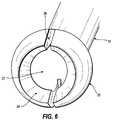
- FIG. 6is an end perspective view of yet another alternative embodiment of the connector device of the present invention.
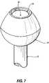
- FIG. 7is an end perspective view of still another alternative embodiment of the connector device of the present invention.
- FIG. 8is an elevation view of the connector device shown in FIG. 7 ;
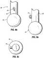
- FIG. 9 ais an front elevation view of one embodiment of the tension link with a link retainer of the present invention.
- FIG. 9 bis a side elevation view of the tension link with link retainer shown in FIG. 7 a;
- FIG. 9 cis an end view of the tension link with link retainer shown in FIG. 7 a;
- FIG. 10 ais an front elevation view of an alternative embodiment of the tension link with a link retainer of the present invention.
- FIG. 10 bis a side elevation view of the tension link with link retainer shown in FIG. 8 a;
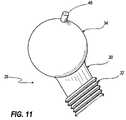
- FIG. 11is a perspective view of the tension link with head end process of the present invention.
- FIG. 12is a side elevation view of one embodiment of the connector of the present invention.
- FIG. 13is a side perspective view of an alternative embodiment of the connector of the present invention.
- FIG. 14is an bottom perspective view of the connector shown in FIG. 11 ;
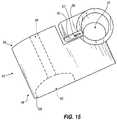
- FIG. 15is a side perspective view of another alternative embodiment of the connector of the present invention.
- FIG. 16is a side elevation view of yet another alternative embodiment of the connector of the present invention.
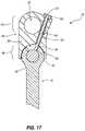
- FIG. 17is a cross-sectional view of one embodiment of the surgical implant assembly of the present invention.
- FIG. 18is a perspective view of an alternative embodiment of the surgical implant assembly of the present invention.
- FIG. 19 ais a cross-sectional elevation view of another alternative embodiment of the surgical implant assembly of the present invention.
- FIG. 19 bis a plan view of the surgical implant assembly shown in FIG. 19 a.
- the attachment device 10includes a shank 12 having a first end 14 and a second end 16 .
- the first end 14 of the shank 12includes a securement mechanism 18 .
- the securement mechanism 18may be screw threads. It is noted, however, that the securement mechanism 18 may include any known method of securing one item to another.
- the securement mechanism 18may be a hook, a plate, a flange, or adhesive.
- the securement mechanism 18may require additional hardware such as screws, bolts, or adhesive to secure the plate or flange to the intended object.
- additional hardwaresuch as screws, bolts, or adhesive
- the adhesivewould necessarily be applied to the securement mechanism 18 , not included within it. Additionally, adhesive could be used with the securement mechanism 18 , e.g., applied to screw threads, for additional securement capacity.
- the second end 16 of the shank 12generally comprises an enlarged area 20 including a central core 22 and an aperture 24 .
- the second end 16 of FIG. 1is shown in cross-sectional view to more clearly show the central core 22 and the aperture 24 .
- the enlarged area 20includes a hollow core 22 and a central aperture 24 .
- the enlarged areaalso includes an entry channel 26 .
- the entry channel 26is operatively connected with the hollow core 22 such that a tension link 28 , having a shaft 30 with a threaded end 32 and a head end 34 , may be inserted, threaded end 32 first, through the entry channel 26 , the hollow core 22 , and central aperture 24 until the head end 34 of the tension link 28 is retained within the hollow core 22 by the central aperture 24 .
- FIG. 3clarifies the operational relationship between the entry channel 26 , the hollow core 22 and the central aperture 24 .
- FIG. 4an alternative embodiment of the attachment device 10 is shown.
- This embodimentis similar to the embodiment of FIGS. 2 and 3 , but with an additional element.
- a tension link slot 36is provided between the entry channel 26 and the central aperture 24 .
- the tension link slot 36allows the shaft 30 of the tension link 28 to be inserted through the tension link slot 36 .
- the tension link 28may be inserted through the tension link slot 36 to pass through both central aperture 24 and the entry channel 26 .
- the tension link 28may then be drawn through the aperture 24 until the tension link head end 34 passes through the entry channel 26 and rests in the hollow core 22 .
- This embodimentmay allow the surgeon to insert a tension link 28 into an attachment device 10 secured to the human body in cases where the obstacles, including the human body itself, or parts thereof, prevent the length of the tension link 28 from extending completely beyond the entry channel 26 opposite the central aperture 24 .
- FIG. 5shows an end view, from the second end 16 , of the embodiment of the attachment device 10 from FIG. 4 .
- FIG. 5clarifies the relationship between the tension link slot 36 and the central aperture 24 , the hollow core 22 and the entry channel 26 .
- the central aperture 24is shown in FIG. 5 as located at top dead center of the enlarged portion 20 of the attachment device 10 .
- the location of the central aperture 24may be at any angular relationship to the shank 12 . This location of the central aperture 24 applies to this, and every other, embodiment of the attachment device 10 .
- the hollow core 22should be sized to receive the head end 34 of the tension link 28 , in this and other embodiments of the present invention.
- the central aperture 24should be sized to accommodate the tension link shaft 30 , and with enough clearance to provide the desired angular displacement. For example, it may be desirable to provide from about 0 to 60 degrees of angular displacement of the tension link 28 from the longitudinal axis of the attachment device 10 . In some instances, a smaller range may be advantageous.
- the enlarged area 20 of the attachment device 10includes a hollow core 22 and a central aperture 24 , but does not include an entry channel 26 . Instead, at least one expansion slot 38 extends from the central aperture 24 along the exterior surface of the enlarged area 20 .
- the expansion slot 38extends completely through the wall defined by the hollow core 22 and the exterior surface of the enlarged area 20 .
- the embodiment of FIG. 6includes two expansion slots 38 diametrically opposite from one another, however, the number of expansion slots 38 and their location in radial relation to the central aperture 24 may be selected in the design of the attachment device 10 according to, among other things, the application, or the size and material of construction of the attachment device 10 .
- the expansion slots 38may allow insertion of the head end 34 of the tension link 28 into the hollow core 22 through the central aperture 24 by allowing deformation of the enlarged area 20 .
- the connector 40more specifically, the head receptacle 42 of the connector 40 , when properly installed over the enlarged area 20 prevents further deformation of the enlarged area 20 , and thus the central aperture 24 retains the head 34 of the tension link 28 within the hollow core 22 .
- the enlarged area 20 of the attachment device 10includes a substantially conical portion around the central aperture 24 .
- the head receptacle 42 of the connector 40has mating geometry to the enlarged area 20 .
- the partially conical shape of the enlarged area 20allows polyaxial positioning of the connector 40 while controlling movement in one degree of freedom.
- the connector 40may rotate around the central axis of the conical section, however, the mating geometry of the head receptacle 42 prevents angular displacement relative to the central axis of the conical section.
- the central aperture 24may require that the shape of the enlarged area 20 not be truly conical.
- the central aperture 24may necessitate the geometry of the enlarged area 20 to be more aptly described as a truncated cone shape.
- FIG. 8shows the embodiment of the attachment device 10 of FIG. 7 in an elevation view. While FIG. 8 shows the enlarged area 20 to include a hollow core 22 , a central aperture 24 , and an entry channel 26 , it is noted that conical-shaped enlarged area 20 shown in FIGS. 7 and 8 may be used with any alternative embodiments of the attachment device 10 related to the method of insertion of the tension link head 34 into the hollow core 22 , including, for example, the expansion slots 38 , or the tension link slot 36 .
- the exterior surface of the enlarged area 20may other configurations.
- the exterior surface of the enlarged area 20may be formed as a polyhedron, such as a dodecahedron, or be provided with facets.
- the head receptacle 42 of the connector 40will also have a corresponding geometry. In this way, a polyaxial relationship is provided between the attachment device 10 and the connector 40 , yet limiting this polyaxial relationship to a finite number of angular displacement.
- the enlarged area 20is shown in the drawings as at least approximately spheric. It is noted, however that the enlarged area 20 and/or the head receptacle 42 of the connector 40 may also be aspheric. The use of the aspheric construction of either the enlarged area 20 or the head receptacle 42 , or both, may accommodate the elasticity and deformation of the material the structure.
- the amount of asphericitymay be selected to control the area of surface contact between the enlarged area 20 and the head receptacle 42 of the connector 40 . The amount of asphericity may also be selected to control or vary the degree of freedom required by the linkage.
- the external surface of the enlarged area 20may be textured, i.e., provided with a specified surface roughness.
- the texture, or surface roughness, of the enlarged area 20may be selected to properly control the friction between the enlarged area 20 and the head receptacle 42 , and thus controlling, among other things, the tension force required to secure the devices together or degrees of freedom in their combination.
- the internal wall of the hollow core 22 , the head end 34 of the tension link 28 , and/or the head receptacle 42 of the connector 40may also be provided with a texture, or surface roughness.
- the tension link 28is generally a shaft 30 with a head end 34 and a thread end 32 .
- one embodiment of the tension link 28may include a link retainer 44 .
- the link retainer 44in this embodiment, comprises a projection on the shaft 30 of the tension link 28 .
- the link retainer 44may be used to prevent unwanted rotation, but not angular orientation, of the tension link 28 within the hollow core 22 of the attachment device 10 .
- FIG. 9 ashows an embodiment of the tension link with a link retainer 44 in partial side elevation.
- FIG. 9 bshows the same embodiment in front elevation.
- FIG. 9 cshows this embodiment in plan view as seen from the thread end 32 of the tension link 28 .
- the thread end 28 of the tension link 28is not shown in FIGS. 9 a , 9 b , and 9 c.
- FIGS. 10 a and 10 ban alternative embodiment of the link retainer 44 of the tension link 28 is shown.
- the tension link 28is shown in partial side elevation and partial front elevation, in FIG. 10 a and FIG. 10 b , respectively. Again, this view is “partial” because the thread end 32 of the tension link 28 is omitted from the drawing.
- the link retainer 44 in this embodimentis a projection that spans the intersection of the shaft 30 and the head end 34 of the tension link 28 and extends partially along the surface of the head end 34 .
- This embodimentmay be used in conjunction with the embodiment of the attachment device 10 including the tension link slot 36 , as shown in FIGS. 4 and 5 above.
- the tension linkmay be prevented from unwanted rotation of the tension link 28 within the hollow core 22 .
- the link retainer 44may be placed in contact with the wall of the tension link slot 36 to prevent such rotation.
- the tension link 28again includes a shaft 30 with a head end 34 and a thread end 32 , and, in this embodiment, a head end process 46 .
- the head end process 46is a projection on the head end 34 of the tension link 28 .
- the head end process 46may be used to prevent rotation of the tension link 28 within the hollow core 22 similar to the link retainer 44 .
- this embodimentwould most commonly be used with an attachment device 10 having a entry channel 26 , and the head end process 46 could be placed in contact with a wall of the entry channel 26 to prevent the rotation.
- the connectorhas a receiving end 48 and a rod end 50 .
- the receiving end 48includes a head receptacle 42 for receiving the enlarged area 20 of the attachment device 10 .
- the rod end 50includes a rod aperture 52 for receiving a implant component 54 , such as a spinal rod implant or other device.
- a tension link cavity 56is provided from the head receptacle 42 to the rod end 50 .
- the tension link cavity 56is sized to allow the insertion of the thread end 32 of a tension link 28 through the connector 40 .
- a link nut recess 58is provided at the rod end 50 adjacent to the tension link cavity 56 for seating a link nut 60 used to secure the connector 40 to the tension link 28 .
- the connectormay include a gap 62 located medially between the receiving end 48 and the rod end 50 , and in operative relationship with the rod aperture 52 such that when the gap 62 is closed, the rod aperture 52 may secure the implant component 54 .
- tightening of the link nut 60 on the tension link 28closes the gap 62 , and thus secures the implant component 54 , concurrently with securing the connector 40 to the attachment device 10 in a desired position.
- the embodiment shown in FIG. 12includes the alternative feature of a link retainer recess 64 .
- the link retainer recess 64is a void located along the tension link cavity 56 and adjacent to the head receptacle 42 .
- the link retainer recess 64accommodates the link retainer 44 of the embodiment shown in FIG. 9 a , 9 b and 9 c , such that the link retainer 44 may contact the wall of the link retainer recess 64 and prevent undesired rotation of the tension link 28 .
- the link retainer recess 64should be sized accordingly.
- the connector 40 of this embodimenthas a receiving end 48 with a head receptacle 42 , a rod end 50 with a rod aperture 52 , and a tension link cavity 56 .
- the rod aperture 52is offset from the body of the connector 40 . The ability to offset the rod aperture 52 may provide greater latitude to the surgeon when attempting to avoid obstacles such as bones or other tissues.
- FIG. 14shows the embodiment of the connector 40 of FIG. 13 from the receiving end 48 .
- the tension link cavity 56 in this embodimentdoes not include the alternative element of the link retainer recess 64 .
- FIG. 15an alternative embodiment of the connector 40 is shown.
- the implant component 54is secured in the rod aperture 52 separately from securing the connector 40 to the attachment device 10 by the tension link 28 .
- the tension link cavity 56does not intersect the gap 62 in the wall of the rod aperture 52 .
- a portion of the wall of the rod apertureforms a tab 66 with a implant securement hole 67 .
- the tab 66may be secured to the connector 40 by a implant securement screw 69 inserted through the implant securement hole 67 and into the connector 40 . This configuration may provide further offset capacity for the connector from the attachment device 10 .
- FIG. 16a further embodiment of the connector 40 is provided wherein the implant component 54 is secured in the rod aperture 52 separately from securing the connector 40 to the attachment device 10 .
- a portion of the wall of the rod apertureforms a tab 66 with a implant securement hole 67 .
- the tab 66may be secured to the connector 40 by a implant securement screw 69 inserted through the implant securement hole 67 and into the connector 40 .
- the tab 66is located toward the exterior of the connector 40 .
- the surgical implant system 70includes a attachment device 10 , a tension link 28 , a connector 40 , and a link nut 60 .
- the implant component 54is omitted from this drawing.
- the tension link head end 34is inserted into the hollow core 22 of the attachment device 10 .
- the tension link 28extends through the tension link cavity 56 of the connector 40 such that the enlarged area 20 of the attachment device 10 is received into the head receptacle 42 of the connector 40 .
- the connector 40may then be secured to the attachment device 10 in proper position by tightening the link nut 60 on the tension link 28 . In this embodiment, tightening the link nut 60 will also close the rod aperture gap 62 and secure the implant component 54 within the rod aperture 52 .
- the head receptacle wall 68is shown extending to approximately the “equator” or diameter of the enlarged area 20 of the attachment device 10 . It should be noted that the extent that the head receptacle wall 68 engages the enlarged area 20 may be varied. For instance, a smaller wall 68 engagement may be desirable to increase the polyaxial adjustment of the assembly. Alternatively, it may be desirable to provide greater wall 68 engagement with the enlarged area 20 to prevent unnecessary deformation of the enlarged area 20 , for example when the enlarged area 20 is provided with an expansion slot 38 or a tension link slot 36 .
- the head receptacle wall 68may match the contour of the enlarged area 20 .
- the size of the head receptacle 42at the farthest point on the receiving end 48 of the connector 40 , may be smaller than the maximum size of the enlarged area 20 at its “equator.” This may provide an additional advantage to the surgeon. In this situation, a tactile or audible signal may be provided when the enlarged area 20 is properly received into the head receptacle 42 .
- the connectors 40secure a implant component 54 , in this case a rod, to the attachment devices 10 .
- the orientation of the attachment devices 10illustrate the polyaxial nature of the system 70 .
- the attachment devicesmay be secured to whatever structure is necessary at different angles and on different planes.
- FIGS. 19 a and 19 ban alternative embodiment of the surgical implantation system 70 is provided.
- a dynamic systemis created wherein the implant component 54 is allowed to move freely along its longitudinal axis within connector rod aperture 52 . This is accomplished by manufacturing some clearance tolerance within the rod aperture 52 when the link nut 60 is completely tightened on tension link 28 .
- FIG. 19 aalso shows an alternative embodiment of a retaining recess 72 adjacent to the connector rod aperture 52 .
- the retaining recess 72corresponds with a retaining process 74 on the implant component 54 to limit the extent of dynamic nature within the implant.
- the retaining recess 72 and the retaining process 74are sized and work in relation to one another such that the longitudinal movement of the implant component 54 is arrested when the retaining process 74 nests in the retaining recess 72 .
- the retaining process 74without the retaining recess 72 . It this aspect, the longitudinal movement of the implant component 54 is arrested when the retaining process 74 contacts the exterior surface of the connector 40 at the rod aperture 52 . It is also possible to use either of the two above embodiments on either side of the rod aperture 52 , wherein the longitudinal movement of the implant component 54 can be constrained in one or both directions.
- the attachment device 10may be used in conjunction with a hook in place of the tension link 28 .
- the hookwould have a ball end and a hook end. The ball end would be inserted into the central core 22 of the attachment device 10 and the hook end would be used to secure some bodily structure, such as a bone.
- the hook rodwould be capable of polyaxial movement.
- the present inventionalso relates to a method of using the embodiments as set forth above.
- the method using a surgical implant system 70would first require the selective insertion of the attachment device 10 into a human bone.
- the tension link head end 34could then inserted into the hollow core 22 of the attachment device 10 .
- the step of insertion of the head end 34would depend upon the embodiment of the attachment device 10 selected. For example, if a attachment device 10 with an entry channel 26 , but no tension link slot 36 , is provided, the tension link 28 is positioned in the aperture 24 by way of the entry channel 26 .
- the connector 40is positioned on the tension link 28 by inserting the tension link 28 through the connector tension link cavity 56 .
- the surgeoncan position the connector 40 such that the implant component 54 , when properly inserted in connector rod aperture 52 , is held in the desired position along the spinal column.
- the surgeoncan then secure the position of the implant component 54 and the connector 40 in relation to the attachment device 10 by tightening the link nut 60 on the tension link threaded end 32 .
- This processis repeated, as necessary, along the spinal column at various points along the implant component 54 .
- the surgeonhas implemented the above described embodiments as a method for using the surgical implant system, for example, in repairing a degenerative spinal condition.
- the polyaxial securing mechanism of the present inventionis not limited to medical implants.
- the present inventioncould be used to secure guy wires or rods.
- the anchor screwcould be inserted into the ground, e.g., set directly in to the soil, mounted in a concrete footing, or similar mounting.
- the guy wire or rodi.e., the tension link
- the guy rodmay include a turnbuckle. The turn buckle can then be adjusted to the desired tension in the guy rod. In this way, some room for error in the location of the anchor bolt is built into the installation process.
- the guy rodmay be installed between the anchor screw and the structure without placing undue stress on the guy rod, or requiring unnecessary bending of the guy rod, due to misalignment between the connection point on the structure and the anchor bolt position. This is especially beneficial when a turnbuckle is implemented in the guy rod.
- the polyaxial nature of the anchor screwwould allow the turnbuckle to be more easily adjusted since the stress within the guy rod is limited to the axial direction of the rod, i.e., no bending stress on the turnbuckle.
Landscapes
- Health & Medical Sciences (AREA)
- Orthopedic Medicine & Surgery (AREA)
- Life Sciences & Earth Sciences (AREA)
- Neurology (AREA)
- Surgery (AREA)
- Heart & Thoracic Surgery (AREA)
- Engineering & Computer Science (AREA)
- Biomedical Technology (AREA)
- Nuclear Medicine, Radiotherapy & Molecular Imaging (AREA)
- Medical Informatics (AREA)
- Molecular Biology (AREA)
- Animal Behavior & Ethology (AREA)
- General Health & Medical Sciences (AREA)
- Public Health (AREA)
- Veterinary Medicine (AREA)
- Surgical Instruments (AREA)
- Prostheses (AREA)
Abstract
Description
This application is a divisional of U.S. patent application Ser. No. 09/898,478 filed on Jul. 2, 2001 now U.S. Pat. No. 6,736,816 and entitled “POLYAXIAL CONNECTION DEVICE AND METHOD”, which claimed priority from U.S. Provisional Patent Application No. 60/215,602 filed on Jun. 30, 2000. The entire disclosures of these applications are considered to be part of the disclosure of the present application and are hereby incorporated by reference in their entirety.
This invention relates generally to polyaxial securement devices and, more particularly, to a screw for insertion into human bone having a polyaxial coupling for adjustably mounting a foreign object to the bone and, even more particularly, to a screw for insertion into spinal bone having a polyaxial coupling and locking mechanism for mounting a stabilizing rod to a sequence of vertebrae.
The use of fixation devices for the treatment of vertebrae deformities and injuries is well known in the art. Various fixation devices are used in medical treatment to correct curvatures and deformities, treat trauma and remedy various abnormal spinal conditions. Treatment of these conditions generally requires the implantation of various component pieces such as support rods, crosslinks, caudal facing hooks, cranial facing hooks and like components, which form a spinal implant system.
It is necessary in spinal implant systems to properly anchor the system to bone to provide necessary support of the implant. Bone screws are commonly used for anchoring spinal implant systems. However, there are several problems with the use of fixed screws for anchoring spinal implants. The exact final position of a bone screw is difficult, if not impossible, to predict prior to the exposure of the patient's bone. This unpredictability results from the uncertainty of exact bone formation and shape within an individual patient. Additionally, it can be difficult to predetermine the structure of the bone, i.e. whether the bone is soft or even osteoporotic. Even if the final position of the screw can be predetermined, the necessary shape and position of a spinal rod implant may create unwanted stress upon the bone screw or the bone itself. This is especially true where a plurality of screws is required along the spinal column for securement of an implant. The alignment of the rod with several screws along the vertebrae compounds this problem and makes undesired stress much more probable. Moreover, this misalignment may influence the extent and speed of correction of the spinal defect.
It is thus desirable to have a polyaxial securement method. There exists a number of patents drawn to polyaxial bone screws. Unfortunately, the advantage of many of these designs comes at the expense of bulk in the connection means or complexity of implantation. As the size of a bone screw increases, so too does the displacement of normal bodily formations, such as muscular tissue or bone. It is common in the insertion of spinal implants to necessarily remove portions of vertebral bone to allow proper insertion of a bone screw. Moreover, this bulk may result in long-term muscular displacement that may lead to a patient's pain or discomfort.
Increased complexity of the installation procedure is undesirable because it increases a patient's time in surgery. Increased operating time is known to increase the risk of many complications associated with surgery. The additional time necessary to remove, or even temporarily dislocate, bone or muscular tissue also increases operating time, and thus the risk of complications.
It is also desirable with some patients to have a spinal implant system that allows the vertebral column to settle naturally under the weight of the human body. Human bone heals more readily under some pressure. In a rigid spinal implant system, the patient's spinal column may be unnaturally held apart by the structure of the implant. It is possible that this stretching of the vertebrae, in relation to one another, results in delayed or incomplete healing of the bone.
In view of the above, there is a long felt but unsolved need for a method and system that avoids the above-mentioned deficiencies of the prior art and that provides an effective system that is relatively simple to employ and requires minimal displacement or removal of bodily tissue.
In accordance with the present invention, a polyaxial connector device is provided with a socket for receiving a headed connecting link. A surgical implant assembly employing the polyaxial connector device is also disclosed. The surgical implant assembly of the present invention includes an attachment device, a headed anchor shaft (or tension link), and a connector. The attachment device of the present invention has a shank with a securement mechanism on one end and an enlarged area on the other end. The securement mechanism may be selected from any known method of securing one article to another, for example, a hook, a plate, a flanged device, or an adhesive, however, it is anticipated that the most common securement mechanism used will be screw threads. The enlarged area includes a hollow core, i.e., a socket, and a central aperture providing access to the hollow core. The enlarged area need only be large enough to envelop the head of the anchoring shaft and provide a wall thickness necessary for strength considerations.
The attachment device may include additional features to enable the insertion of the head end of the tension link into the hollow core. The enlarged area of the attachment device may include an entry channel, leading to the hollow core, that accommodates the tension link head end so that the tension link may be advanced, shaft end first, until the head of the tension link is positioned within the hollow core. Additionally, the entry channel and the central aperture may be connected by an slot through the wall of the enlarged area. In this way, the tension link head end may be positioned within the hollow core without extending the entire length of the tension link beyond the enlarged area of the attachment device opposite the central aperture. The surgeon may place only the head end of the tension link at the entry channel, slide the tension link shaft through the tension link slot, and draw the head end into the hollow core. Alternatively, in lieu of an entry channel or tension link slot, the enlarged area may include one or more expansion slots. In this embodiment, the head of the tension link may be inserted into the hollow core through the central aperture by the application of enough force to expand the central aperture. Once the head of the tension link is properly received into the hollow core, the enlarged area returns to its original size and shape. Unwanted expansion of the enlarged area is prevented by the connector once the enlarged area is properly seated into a head receptacle on the connector during implantation. This maintains the head of the tension link within the hollow core.
The external surface of the enlarged area of the attachment device may be formed into one of limitless geometries. For example, the external surface may be spherical, or at least semi-spherical. The external surface may be at least slightly aspheric. By controlling the degree of asphericity, the contact surface between the attachment device and the connector can thereby control the degree of freedom of the connector relative to the attachment device. Alternatively, the external surface may be conical, or a truncated cone shape, to allow rotational freedom while maintaining a coaxial relationship between the attachment device and the connector. Also, the external surface may be polyhedral or provided with facets to allow angular displacement in only finite steps or prevented altogether. In embodiments including conical, truncated cone shape, polyhedral or faceted geometries of the external surface of the enlarged area, the mating head receptacle of the connector may have corresponding geometry.
The tension link secures and maintains the position of the connector relative to the attachment device. The tension link is a shaft with a head end and a thread end. The head end, as described above, is contained within the hollow core of the attachment device. The threaded end extends through the connector and is secured to the connector by a link nut threaded onto the thread end.
The tension link may be provided with a projection to prevent undesirable rotation of the link when tightening or loosening the link nut, yet still enable angular displacement necessary to provide a polyaxial connection. In one embodiment, a link retainer, or a projection, may be provided on the shaft of the tension link. In this embodiment, it is necessary to provide a link retainer recess within the tension link cavity of the connector. In an alternative embodiment, the link retainer, or projection, may be provided at the intersection of the tension link shaft and the head end, and extending over a portion of the surface of the head end. In this embodiment, used with the attachment device embodiment including a tension link slot, the rotation may be prevented by contacting the link retainer with one side of the tension link slot. In either of the two foregoing embodiments, it is desirable to undersize the link retainer, relative to the link retainer recess or the tension link slot, so that the polyaxial freedom of the tension link and attachment device combination is not unduly limited. In an alternative embodiment, a retaining process, or small projection, may be provided on the tension link head. The retaining process should be positioned such that the retaining process is within the entry channel. Undesired rotation may be prevented by contacting the small projection with the wall of the entry channel.
The connector couples the attachment device to the implant component, such as a spinal rod implant. The connector has a connecting end with a head receptacle, a rod end with a rod aperture, and a tension link cavity. The tension link, with its head positioned in the hollow core of the attachment device, is inserted through the tension link cavity so that an enlarged area of the attachment device nests in the head receptacle. The rod aperture secures the implant component in a desired position. The rod aperture may be secured by the tension link when the link nut is threaded and tightened on the link. In this embodiment, the rod end of the connector has a gap on one side of the rod aperture. The tension link cavity extends continuously through the tension link on both sides of the gap. The upper portion of the rod end forms a tab. As the tab is drawn toward the receiver end of the connector the gap narrows until the rod aperture firmly clamps the implant component or until the gap is drawn completely together.
In still other embodiments, it may also be desirable to provide a separate system for securing the connector to the attachment device and for securing the implant component to the connector. Therefore, in an alternative embodiment, the gap is connected to the rod aperture in a position that does not intersect the rod aperture. In this embodiment, a separate screw, or other connection device, is required to secure the implant component in the rod aperture. The tension link is then used to secure the connector to the attachment device.
In either of the two foregoing connector embodiments, it may be desirable to secure the rod within the rod aperture without clamping to the extent axial movement of the rod within the rod aperture is prevented. In this way, for example, the spine may settle under its own weight and provide a better healing environment for the bone. In conjunction with this embodiment, the implant component may be supplied with flanges, or other extensions to constrain axial movement of the implant component within a desired range.
To surgically implant a device of the present invention, the surgeon may attach an attachment device, selected from one of the embodiments of the present invention. After successful attachment, the surgeon may insert a tension link of the present invention by positioning the head end of the tension link within the hollow core of the attachment device. The surgeon may then place a connector, with a head receptacle designed for mating with the second end of the attachment device, upon the attachment device by inserting the tension link through the tension link cavity of the connector. At this point, the surgeon may select the desired angle of position of the connector for attaching a implant component. Once the connector is properly adjusted, the link nut may be secured to the tension link, thereby securing the elements together in the desired position. The link nut may be loosened, as necessary, to readjust the placement of the implant component. Alternatively, if a connector having a separate implant component securement device is used, the step of securing the link nut may be delayed until after the implant component is secured in the rod aperture and properly positioned.
Based on the foregoing summary, a number of worthwhile aspects of the present invention can be readily identified. A connector device is provided with a small and simple polyaxial adjustment mechanism. The minimal size of the enlarged area of the connector device allows attachment of the device to human bone without significant displacement of human tissue. Therefore, the complexity of surgery and the following pain and discomfort of the patient may be minimized. The polyaxial nature of the device, combined with the small size, may allow a surgeon to attach the securement device to a secure portion of the human body without the need to remove bony processes to accommodate a larger attachment device. Additionally, a simple surgical implant assembly, including the polyaxial attachment device, is provided. The simplicity of the elements, and the assembly process thereof, may reduce the patient's time in surgery, thus reducing the risk and probability of surgical complications. Finally, a number of embodiments of the present invention may be used in combination to allow the surgeon great latitude in selection of materials. The surgeon may select from different embodiments of the attachment device, the tension link, and the connector to best fit the surgical implant parameters. With these choices the surgeon may then best determine which embodiments of which elements to select to minimize removal or displacement of bodily tissue or bone, and thereby reduce both the patient's risk of surgical complications and post-surgical pain and discomfort.
Additional advantages of the present invention will become readily apparent from the following discussion, particularly when taken together with the accompanying drawings.
With reference toFIG. 1 , one embodiment of the attachment device (or connection device) of the present invention is shown in partial cross-section. Theattachment device 10 includes ashank 12 having afirst end 14 and asecond end 16. Thefirst end 14 of theshank 12 includes asecurement mechanism 18. As shown inFIG. 1 , thesecurement mechanism 18 may be screw threads. It is noted, however, that thesecurement mechanism 18 may include any known method of securing one item to another. For example, thesecurement mechanism 18 may be a hook, a plate, a flange, or adhesive. In the case of thesecurement mechanism 18 as a flange or plate, thesecurement mechanism 18 may require additional hardware such as screws, bolts, or adhesive to secure the plate or flange to the intended object. In the case of thesecurement mechanism 18 as an adhesive, or requiring the additional use of adhesive, the adhesive would necessarily be applied to thesecurement mechanism 18, not included within it. Additionally, adhesive could be used with thesecurement mechanism 18, e.g., applied to screw threads, for additional securement capacity.
Thesecond end 16 of theshank 12 generally comprises anenlarged area 20 including acentral core 22 and anaperture 24. Thesecond end 16 ofFIG. 1 is shown in cross-sectional view to more clearly show thecentral core 22 and theaperture 24.
With reference toFIG. 2 , an embodiment of thesecond end 16 of theshank 12 is shown. In this embodiment, theenlarged area 20 includes ahollow core 22 and acentral aperture 24. The enlarged area also includes anentry channel 26. Theentry channel 26 is operatively connected with thehollow core 22 such that atension link 28, having ashaft 30 with a threadedend 32 and ahead end 34, may be inserted, threadedend 32 first, through theentry channel 26, thehollow core 22, andcentral aperture 24 until thehead end 34 of thetension link 28 is retained within thehollow core 22 by thecentral aperture 24.
With reference toFIG. 3 , the embodiment of thesecond end 16 ofattachment device 10 is shown in cross-section.FIG. 3 clarifies the operational relationship between theentry channel 26, thehollow core 22 and thecentral aperture 24.
With reference toFIG. 4 , an alternative embodiment of theattachment device 10 is shown. This embodiment is similar to the embodiment ofFIGS. 2 and 3 , but with an additional element. In this embodiment, atension link slot 36 is provided between theentry channel 26 and thecentral aperture 24. Thetension link slot 36 allows theshaft 30 of thetension link 28 to be inserted through thetension link slot 36. In this way, thetension link 28 may be inserted through thetension link slot 36 to pass through bothcentral aperture 24 and theentry channel 26. Thetension link 28 may then be drawn through theaperture 24 until the tension link head end34 passes through theentry channel 26 and rests in thehollow core 22. This embodiment may allow the surgeon to insert atension link 28 into anattachment device 10 secured to the human body in cases where the obstacles, including the human body itself, or parts thereof, prevent the length of the tension link28 from extending completely beyond theentry channel 26 opposite thecentral aperture 24.
With reference toFIG. 6 , an additional alternative embodiment of theenlarged area 20 of theattachment device 10 is shown. In this embodiment, theenlarged area 20 includes ahollow core 22 and acentral aperture 24, but does not include anentry channel 26. Instead, at least one expansion slot38 extends from thecentral aperture 24 along the exterior surface of theenlarged area 20. The expansion slot38 extends completely through the wall defined by thehollow core 22 and the exterior surface of theenlarged area 20. The embodiment ofFIG. 6 includes two expansion slots38 diametrically opposite from one another, however, the number of expansion slots38 and their location in radial relation to thecentral aperture 24 may be selected in the design of theattachment device 10 according to, among other things, the application, or the size and material of construction of theattachment device 10. The expansion slots38 may allow insertion of thehead end 34 of thetension link 28 into thehollow core 22 through thecentral aperture 24 by allowing deformation of theenlarged area 20. As explained in more detail below, theconnector 40, more specifically, thehead receptacle 42 of theconnector 40, when properly installed over theenlarged area 20 prevents further deformation of theenlarged area 20, and thus thecentral aperture 24 retains thehead 34 of thetension link 28 within thehollow core 22.
With reference toFIG. 7 , yet another alternative embodiment of theenlarged area 20 of theattachment device 10 is shown. In this embodiment, at least a portion of theenlarged area 20 includes a substantially conical portion around thecentral aperture 24. Thehead receptacle 42 of theconnector 40 has mating geometry to theenlarged area 20. Thus, the partially conical shape of theenlarged area 20 allows polyaxial positioning of theconnector 40 while controlling movement in one degree of freedom. Theconnector 40 may rotate around the central axis of the conical section, however, the mating geometry of thehead receptacle 42 prevents angular displacement relative to the central axis of the conical section. Obviously, thecentral aperture 24 may require that the shape of theenlarged area 20 not be truly conical. Thecentral aperture 24 may necessitate the geometry of theenlarged area 20 to be more aptly described as a truncated cone shape.
In alternative embodiments not shown in the drawings, the exterior surface of theenlarged area 20 may other configurations. For example, the exterior surface of theenlarged area 20 may be formed as a polyhedron, such as a dodecahedron, or be provided with facets. In this embodiment, thehead receptacle 42 of theconnector 40 will also have a corresponding geometry. In this way, a polyaxial relationship is provided between theattachment device 10 and theconnector 40, yet limiting this polyaxial relationship to a finite number of angular displacement.
Theenlarged area 20 is shown in the drawings as at least approximately spheric. It is noted, however that theenlarged area 20 and/or thehead receptacle 42 of theconnector 40 may also be aspheric. The use of the aspheric construction of either theenlarged area 20 or thehead receptacle 42, or both, may accommodate the elasticity and deformation of the material the structure. The amount of asphericity may be selected to control the area of surface contact between theenlarged area 20 and thehead receptacle 42 of theconnector 40. The amount of asphericity may also be selected to control or vary the degree of freedom required by the linkage.
Further, in any embodiment or configuration of theenlarged area 20, the external surface of theenlarged area 20 may be textured, i.e., provided with a specified surface roughness. The texture, or surface roughness, of theenlarged area 20 may be selected to properly control the friction between theenlarged area 20 and thehead receptacle 42, and thus controlling, among other things, the tension force required to secure the devices together or degrees of freedom in their combination. It should be noted that the internal wall of thehollow core 22, thehead end 34 of thetension link 28, and/or thehead receptacle 42 of theconnector 40 may also be provided with a texture, or surface roughness.
With reference toFIGS. 9 a,9b, and9c, atension link 28 is shown. Thetension link 28 is generally ashaft 30 with ahead end 34 and athread end 32. As shown inFIGS. 9 a,9b, and9c, one embodiment of thetension link 28 may include alink retainer 44. Thelink retainer 44, in this embodiment, comprises a projection on theshaft 30 of thetension link 28. Thelink retainer 44 may be used to prevent unwanted rotation, but not angular orientation, of thetension link 28 within thehollow core 22 of theattachment device 10.
With reference toFIGS. 10 aand10b, an alternative embodiment of thelink retainer 44 of thetension link 28 is shown. Thetension link 28 is shown in partial side elevation and partial front elevation, inFIG. 10 aandFIG. 10 b, respectively. Again, this view is “partial” because thethread end 32 of thetension link 28 is omitted from the drawing. Thelink retainer 44 in this embodiment is a projection that spans the intersection of theshaft 30 and thehead end 34 of thetension link 28 and extends partially along the surface of thehead end 34. This embodiment may be used in conjunction with the embodiment of theattachment device 10 including thetension link slot 36, as shown inFIGS. 4 and 5 above. As in the previous embodiment, the tension link may be prevented from unwanted rotation of thetension link 28 within thehollow core 22. Thelink retainer 44 may be placed in contact with the wall of thetension link slot 36 to prevent such rotation.
With reference toFIG. 11 , an alternative embodiment of thetension link 28 is shown. The tension link28 again includes ashaft 30 with ahead end 34 and athread end 32, and, in this embodiment, ahead end process 46. Thehead end process 46 is a projection on thehead end 34 of thetension link 28. Thehead end process 46 may be used to prevent rotation of thetension link 28 within thehollow core 22 similar to thelink retainer 44. However, this embodiment would most commonly be used with anattachment device 10 having aentry channel 26, and thehead end process 46 could be placed in contact with a wall of theentry channel 26 to prevent the rotation.
With reference toFIG. 12 , an embodiment of theconnector 40 is shown. The connector has a receivingend 48 and arod end 50. The receivingend 48 includes ahead receptacle 42 for receiving theenlarged area 20 of theattachment device 10. Therod end 50 includes arod aperture 52 for receiving aimplant component 54, such as a spinal rod implant or other device. Atension link cavity 56 is provided from thehead receptacle 42 to therod end 50. Thetension link cavity 56 is sized to allow the insertion of thethread end 32 of atension link 28 through theconnector 40. In the embodiment of theconnector 40 shown inFIG. 12 , alink nut recess 58 is provided at therod end 50 adjacent to thetension link cavity 56 for seating alink nut 60 used to secure theconnector 40 to thetension link 28. As shown inFIG. 12 , the connector may include agap 62 located medially between the receivingend 48 and therod end 50, and in operative relationship with therod aperture 52 such that when thegap 62 is closed, therod aperture 52 may secure theimplant component 54. In this embodiment, tightening of thelink nut 60 on thetension link 28 closes thegap 62, and thus secures theimplant component 54, concurrently with securing theconnector 40 to theattachment device 10 in a desired position. The embodiment shown inFIG. 12 includes the alternative feature of alink retainer recess 64. Thelink retainer recess 64 is a void located along thetension link cavity 56 and adjacent to thehead receptacle 42. Thelink retainer recess 64 accommodates thelink retainer 44 of the embodiment shown inFIG. 9 a,9band9c, such that thelink retainer 44 may contact the wall of thelink retainer recess 64 and prevent undesired rotation of thetension link 28. Thelink retainer recess 64 should be sized accordingly.
Referring now toFIG. 13 , an alternative embodiment of theconnector 40 of the present invention is shown. Like the embodiment ofFIG. 13 , theconnector 40 of this embodiment has a receivingend 48 with ahead receptacle 42, arod end 50 with arod aperture 52, and atension link cavity 56. In this embodiment, however, therod aperture 52 is offset from the body of theconnector 40. The ability to offset therod aperture 52 may provide greater latitude to the surgeon when attempting to avoid obstacles such as bones or other tissues.
With reference toFIG. 15 , an alternative embodiment of theconnector 40 is shown. In this embodiment, theimplant component 54 is secured in therod aperture 52 separately from securing theconnector 40 to theattachment device 10 by thetension link 28. Thetension link cavity 56 does not intersect thegap 62 in the wall of therod aperture 52. Instead, a portion of the wall of the rod aperture forms atab 66 with aimplant securement hole 67. Thetab 66 may be secured to theconnector 40 by aimplant securement screw 69 inserted through theimplant securement hole 67 and into theconnector 40. This configuration may provide further offset capacity for the connector from theattachment device 10.
Referring now toFIG. 16 , a further embodiment of theconnector 40 is provided wherein theimplant component 54 is secured in therod aperture 52 separately from securing theconnector 40 to theattachment device 10. As in the embodiment ofFIG. 15 , a portion of the wall of the rod aperture forms atab 66 with aimplant securement hole 67. Thetab 66 may be secured to theconnector 40 by aimplant securement screw 69 inserted through theimplant securement hole 67 and into theconnector 40. However, in this embodiment, thetab 66 is located toward the exterior of theconnector 40.
With reference toFIG. 17 , a possible combination of the above described elements is provided to show a surgical implantation system. Thesurgical implant system 70 includes aattachment device 10, atension link 28, aconnector 40, and alink nut 60. Theimplant component 54 is omitted from this drawing. The tension linkhead end 34 is inserted into thehollow core 22 of theattachment device 10. Thetension link 28 extends through thetension link cavity 56 of theconnector 40 such that theenlarged area 20 of theattachment device 10 is received into thehead receptacle 42 of theconnector 40. Theconnector 40 may then be secured to theattachment device 10 in proper position by tightening thelink nut 60 on thetension link 28. In this embodiment, tightening thelink nut 60 will also close therod aperture gap 62 and secure theimplant component 54 within therod aperture 52.
As an aside, thehead receptacle wall 68 is shown extending to approximately the “equator” or diameter of theenlarged area 20 of theattachment device 10. It should be noted that the extent that thehead receptacle wall 68 engages theenlarged area 20 may be varied. For instance, asmaller wall 68 engagement may be desirable to increase the polyaxial adjustment of the assembly. Alternatively, it may be desirable to providegreater wall 68 engagement with theenlarged area 20 to prevent unnecessary deformation of theenlarged area 20, for example when theenlarged area 20 is provided with an expansion slot38 or atension link slot 36. Further, if thehead receptacle wall 68 is designed for engagement beyond the “equator” of the enlarged area, thehead receptacle wall 68 may match the contour of theenlarged area 20. In other words, the size of thehead receptacle 42, at the farthest point on the receivingend 48 of theconnector 40, may be smaller than the maximum size of theenlarged area 20 at its “equator.” This may provide an additional advantage to the surgeon. In this situation, a tactile or audible signal may be provided when theenlarged area 20 is properly received into thehead receptacle 42.
With reference toFIG. 18 , an alternative arrangement of thesurgical implant system 70 is shown. In this embodiment, theconnectors 40 secure aimplant component 54, in this case a rod, to theattachment devices 10. The orientation of theattachment devices 10 illustrate the polyaxial nature of thesystem 70. The attachment devices may be secured to whatever structure is necessary at different angles and on different planes.
Referring now toFIGS. 19 aand19b, an alternative embodiment of thesurgical implantation system 70 is provided. In this embodiment, a dynamic system is created wherein theimplant component 54 is allowed to move freely along its longitudinal axis withinconnector rod aperture 52. This is accomplished by manufacturing some clearance tolerance within therod aperture 52 when thelink nut 60 is completely tightened ontension link 28.FIG. 19 aalso shows an alternative embodiment of a retainingrecess 72 adjacent to theconnector rod aperture 52. The retainingrecess 72 corresponds with a retainingprocess 74 on theimplant component 54 to limit the extent of dynamic nature within the implant. The retainingrecess 72 and the retainingprocess 74 are sized and work in relation to one another such that the longitudinal movement of theimplant component 54 is arrested when the retainingprocess 74 nests in the retainingrecess 72.
Although it is not shown in the drawings, it is also possible to use the retainingprocess 74 without the retainingrecess 72. It this aspect, the longitudinal movement of theimplant component 54 is arrested when the retainingprocess 74 contacts the exterior surface of theconnector 40 at therod aperture 52. It is also possible to use either of the two above embodiments on either side of therod aperture 52, wherein the longitudinal movement of theimplant component 54 can be constrained in one or both directions.
Additional embodiments of the present invention are not shown in the drawings. For example, it is expected that theattachment device 10 may be used in conjunction with a hook in place of thetension link 28. In this embodiment, the hook would have a ball end and a hook end. The ball end would be inserted into thecentral core 22 of theattachment device 10 and the hook end would be used to secure some bodily structure, such as a bone. The hook rod would be capable of polyaxial movement.
The present invention also relates to a method of using the embodiments as set forth above. In one embodiment, the method using asurgical implant system 70 would first require the selective insertion of theattachment device 10 into a human bone. The tension linkhead end 34 could then inserted into thehollow core 22 of theattachment device 10. The step of insertion of thehead end 34 would depend upon the embodiment of theattachment device 10 selected. For example, if aattachment device 10 with anentry channel 26, but notension link slot 36, is provided, thetension link 28 is positioned in theaperture 24 by way of theentry channel 26. Theconnector 40 is positioned on thetension link 28 by inserting thetension link 28 through the connectortension link cavity 56.
At this point, the surgeon can position theconnector 40 such that theimplant component 54, when properly inserted inconnector rod aperture 52, is held in the desired position along the spinal column. The surgeon can then secure the position of theimplant component 54 and theconnector 40 in relation to theattachment device 10 by tightening thelink nut 60 on the tension link threadedend 32. This process is repeated, as necessary, along the spinal column at various points along theimplant component 54. In this way, the surgeon has implemented the above described embodiments as a method for using the surgical implant system, for example, in repairing a degenerative spinal condition.
It is understood that the present invention has application outside the surgical implantation field. The polyaxial securing mechanism of the present invention is not limited to medical implants. The present invention, for example, could be used to secure guy wires or rods. In this application, the anchor screw could be inserted into the ground, e.g., set directly in to the soil, mounted in a concrete footing, or similar mounting. The guy wire or rod (i.e., the tension link) could then be inserted through the anchor screw and connected to the structure to be secured. The guy rod may include a turnbuckle. The turn buckle can then be adjusted to the desired tension in the guy rod. In this way, some room for error in the location of the anchor bolt is built into the installation process. The guy rod may be installed between the anchor screw and the structure without placing undue stress on the guy rod, or requiring unnecessary bending of the guy rod, due to misalignment between the connection point on the structure and the anchor bolt position. This is especially beneficial when a turnbuckle is implemented in the guy rod. The polyaxial nature of the anchor screw would allow the turnbuckle to be more easily adjusted since the stress within the guy rod is limited to the axial direction of the rod, i.e., no bending stress on the turnbuckle.
This is just one example of the possible applications of the present invention outside the field of medical implants. Other applications, by no means exhaustive, may include connecting legs of a tripod to a base and mounting track lighting fixtures.
While various embodiments of the present invention have been described in detail, it is apparent that modifications and adaptations of those embodiments will occur to those skilled in the art. However, it is to be expressly understood that such modifications and adaptations are within the spirit and scope of the present invention, as set forth in the following claims.
Claims (20)
1. An attachment device adapted for use with a tension link, the tension link including a tension link head and shaft, the device comprising:
a shank having first and second ends,
said first end having a securing mechanism, and
said second end devoid of threads and comprising at least a wall defined by a hollow core, a first expansion slot disposed on said wall, and a central aperture, wherein said wall includes a curved exterior surface, wherein said second end is expandably deformable to accommodate the insertion of the tension link head through the central aperture and into said hollow core, and wherein the tension link head is retained within said hollow core after insertion therein;
wherein said attachment device receivingly accepts a connector, said connector comprising a head receptacle that at least partially surrounds said second end when said connector is seated on said attachment device, said head receptacle having a curved surface for engaging the curved exterior surface of the second end when the connector is seated on the attachment device, wherein when the tension link head is inserted in the hollow core and the connector is seated on the attachment device, said head receptacle limits the deformation of the second end when a tensile force is applied through the tension link, thereby securing the tension link head within the hollow core, said tensile force operating to secure the connector to the attachment device.
2. A method of installing a surgical implant assembly, comprising the steps of:
a) securing an attachment device to human bone, said attachment device having a shank with first and second ends, said second end having a wall defined by a hollow core, a central aperture, and an expansion slot disposed on said wall through said second end to said hollow core;
b) inserting a tension link including a proximal end having a tension link head and a distal end having threads, into said attachment device by expanding said second end of said attachment device and placing said tension link head within said hollow core such that said distal end of said tension link extends through said central aperture;
c) seating a connector onto at least a portion of said second end of said attachment device, wherein said distal end of said tension link extends through a tension link cavity in said connector, further wherein said connector includes a head receptacle to receive said at least a portion of said second end of said attachment device during said seating step;
d) inserting an implant component through an aperture in said connector; and
e) securing said connector to said attachment device, and said implant component to said connector by threading and tightening a link nut onto said distal end of said tension link;
wherein, said head receptacle of said receptacle acts to partially confine said second end of said attachment device and limits expansion of said second end after said securing step.
3. The method as claimed inclaim 2 , wherein during step (e), tightening the link nut causes a closing of a gap, the closing of the gap causing the implant component to be secured within the aperture.
4. A surgical implant assembly, comprising:
an attachment device having first and second ends, said second end comprising an enlarged area including a wall defined by a hollow core, a central aperture contiguous with said hollow core, and at least one expansion slot disposed on said wall, wherein said wall includes a curved exterior surface;
a tension link having a proximal end and a distal end, said proximal end having a tension link head and said distal end including means for securing, said tension link head insertable into said hollow core through said central aperture by deforming said enlarged area using said expansion slot, the tension link head thereby retained within said hollow core; and
a connector having a head receptacle and a tension link cavity, said head receptacle having a curved surface for engaging the curved exterior surface of the second end when the connector is seated on the attachment device, wherein when the tension link head is inserted in the hollow core and the connector is seated on the attachment device, said head receptacle limits the deformation of the second end when a tensile force is applied through the tension link, thereby securing the tension link head within the hollow core, said tensile force being applied by the securing means and operating to secure the connector to the attachment device.
5. The surgical implant assembly as claimed inclaim 4 , wherein said means for securing comprises a link nut threaded onto said distal end of said tension link.
6. The surgical implant assembly as claimed inclaim 4 , further comprising at least a second expansion slot.
7. The surgical implant assembly as claimed inclaim 6 , wherein said second expansion slot is positioned substantially diametrically opposite said at least one expansion slot.
8. The surgical implant assembly as claimed inclaim 4 , wherein said second end is devoid of threads.
9. The surgical implant assembly as claimed inclaim 4 , wherein said first end of said attachment device comprises screw threads.
10. The attachment device as claimed inclaim 4 , wherein said connector further comprises a gap provided in association with an implant component aperture, wherein when an implant component is inserted in said implant component aperture, said tension additionally operates to close said gap to thereby secure said implant component in said implant component aperture.
11. An attachment device adapted for use with a tension link, the tension link including a tension link head and shaft, the device comprising:
a shank having first and second ends,
said first end having a securing mechanism, and
said second end devoid of threads and comprising at least a wall defined by a hollow core, a first expansion slot disposed on said wall, and a central aperture, wherein said wall includes a curved exterior surface, wherein said second end is expandably deformable to accommodate the insertion of the tension link head through the central aperture and into said hollow core, and wherein the tension link head is retained within said hollow core after insertion therein;
wherein said attachment device receivingly accepts a connector, said connector comprising a head receptacle that at least partially surrounds said second end when said connector is seated on said attachment device, said head receptacle having a curved surface for engaging the curved exterior surface of the second end when the connector is seated on the attachment device, wherein when the tension link head is inserted in the hollow core and the connector is seated on the attachment device, said head receptacle limits the deformation of the second end when a tensile force is applied through the tension link, thereby securing the tension link head within the hollow core, said tensile force operating to secure the connector to the attachment device;
wherein said connector further comprises a gap provided in association with an implant component aperture, wherein when an implant component is inserted in said implant component aperture, said tension additionally operates to close said gap to thereby secure said implant component in said implant component aperture.
12. A surgical implant assembly, comprising:
an attachment device having first and second ends, said second end comprising an enlarged area including a wall defined by a hollow core, a central aperture contiguous with said hollow core, wherein said wall includes a curved exterior surface;
a tension link having a proximal end and a distal end, said proximal end having a tension link head and said distal end including means for securing, said tension link head insertable into said hollow core;
an implant component; and
a connector having a head receptacle provided in association with a tension link cavity, and an implant component aperture provided in association with a gap, said implant component aperture operable to receive the implant component, said head receptacle having a curved surface for engaging the curved exterior surface of the second end when the connector is seated on the attachment device, wherein the tension link head is inserted completely into the hollow core and the connector is seated on the attachment device, a tensile force applied by the securing means operates to secure the connector to the attachment device, wherein said tensile force also operates to close said gap to thereby secure the implant component within the implant component aperture, and further wherein said head receptacle limits deformation of said second end of said attachment device when said tensile force is applied.
13. The surgical implant assembly as claimed inclaim 12 , wherein said means for securing comprises a link nut threaded onto said distal end of said tension link.
14. The surgical implant assembly ofclaim 12 wherein said second end of said attachment device includes an expansion slot disposed on said wall and is deformable to accommodate the insertion of the tension link head through the central aperture and into said hollow core, and
wherein the tension link head is retained within said hollow core by an engagement between the head receptacle and the curved exterior surface of the second end, the engagement occurring when the tension link head is inserted in the hollow core and the connector is seated on the attachment device, wherein said engagement is maintained by a tensile force applied by the securing mechanism through the tension link, and operates to limit the deformation of the second end when thereby securing the tension link head within the hollow core.
15. The surgical implant assembly as claimed inclaim 14 , further comprising at least a second expansion slot.
16. The surgical implant assembly as claimed inclaim 15 , wherein said second expansion slot is positioned substantially diametrically opposite said at least one expansion slot.
17. The surgical implant assembly as claimed inclaim 12 , wherein said attachment device includes entry channel operable to receive said tension link.
18. The surgical implant assembly as claimed inclaim 17 , wherein said attachment device includes a tension link slot.
19. The surgical implant assembly as claimed inclaim 12 , wherein said second end is devoid of threads.
20. The surgical implant assembly as claimed inclaim 12 , wherein said first end of said attachment device comprises screw threads.
Priority Applications (1)
| Application Number | Priority Date | Filing Date | Title |
|---|---|---|---|
| US10/776,094US7753939B2 (en) | 2000-06-30 | 2004-02-10 | Polyaxial connection device and method |
Applications Claiming Priority (3)
| Application Number | Priority Date | Filing Date | Title |
|---|---|---|---|
| US21560200P | 2000-06-30 | 2000-06-30 | |
| US09/898,478US6736816B2 (en) | 2000-06-30 | 2001-07-02 | Polyaxial connection device and method |
| US10/776,094US7753939B2 (en) | 2000-06-30 | 2004-02-10 | Polyaxial connection device and method |
Related Parent Applications (1)
| Application Number | Title | Priority Date | Filing Date |
|---|---|---|---|
| US09/898,478DivisionUS6736816B2 (en) | 2000-06-30 | 2001-07-02 | Polyaxial connection device and method |
Publications (2)
| Publication Number | Publication Date |
|---|---|
| US20040172023A1 US20040172023A1 (en) | 2004-09-02 |
| US7753939B2true US7753939B2 (en) | 2010-07-13 |
Family
ID=22803638
Family Applications (2)
| Application Number | Title | Priority Date | Filing Date |
|---|---|---|---|
| US09/898,478Expired - Fee RelatedUS6736816B2 (en) | 2000-06-30 | 2001-07-02 | Polyaxial connection device and method |
| US10/776,094Expired - Fee RelatedUS7753939B2 (en) | 2000-06-30 | 2004-02-10 | Polyaxial connection device and method |
Family Applications Before (1)
| Application Number | Title | Priority Date | Filing Date |
|---|---|---|---|
| US09/898,478Expired - Fee RelatedUS6736816B2 (en) | 2000-06-30 | 2001-07-02 | Polyaxial connection device and method |
Country Status (6)
| Country | Link |
|---|---|
| US (2) | US6736816B2 (en) |
| EP (1) | EP1294295A4 (en) |
| JP (2) | JP2004516040A (en) |
| AU (2) | AU2001280476B2 (en) |
| CA (1) | CA2415072C (en) |
| WO (1) | WO2002002022A1 (en) |
Cited By (4)
| Publication number | Priority date | Publication date | Assignee | Title |
|---|---|---|---|---|
| US20120209332A1 (en)* | 2011-02-14 | 2012-08-16 | Pioneer Surgical Technology, Inc. | Spinal Fixation System And Method |
| US9844398B2 (en) | 2012-05-11 | 2017-12-19 | Orthopediatrics Corporation | Surgical connectors and instrumentation |
| US10557521B2 (en)* | 2018-05-16 | 2020-02-11 | The North Face Apparel Corp. | Stake with cord lock |
| US10898240B2 (en) | 2016-11-18 | 2021-01-26 | Jgmg Bengochea, Llc | Implants and instruments for enhancing vertebral alignment and sagittal balance |
Families Citing this family (133)
| Publication number | Priority date | Publication date | Assignee | Title |
|---|---|---|---|---|
| AU2001280476B2 (en)* | 2000-06-30 | 2005-11-24 | Stephen Ritland | Polyaxial connection device and method |
| US7833250B2 (en) | 2004-11-10 | 2010-11-16 | Jackson Roger P | Polyaxial bone screw with helically wound capture connection |
| US6692434B2 (en) | 2000-09-29 | 2004-02-17 | Stephen Ritland | Method and device for retractor for microsurgical intermuscular lumbar arthrodesis |
| US7166073B2 (en) | 2000-09-29 | 2007-01-23 | Stephen Ritland | Method and device for microsurgical intermuscular spinal surgery |
| US6726689B2 (en) | 2002-09-06 | 2004-04-27 | Roger P. Jackson | Helical interlocking mating guide and advancement structure |
| US8377100B2 (en) | 2000-12-08 | 2013-02-19 | Roger P. Jackson | Closure for open-headed medical implant |
| US6802844B2 (en)* | 2001-03-26 | 2004-10-12 | Nuvasive, Inc | Spinal alignment apparatus and methods |
| FR2823095B1 (en)* | 2001-04-06 | 2004-02-06 | Ldr Medical | RACHIS OSTEOSYNTHESIS DEVICE AND PLACEMENT METHOD |
| US10729469B2 (en) | 2006-01-09 | 2020-08-04 | Roger P. Jackson | Flexible spinal stabilization assembly with spacer having off-axis core member |
| US10258382B2 (en) | 2007-01-18 | 2019-04-16 | Roger P. Jackson | Rod-cord dynamic connection assemblies with slidable bone anchor attachment members along the cord |
| US8292926B2 (en) | 2005-09-30 | 2012-10-23 | Jackson Roger P | Dynamic stabilization connecting member with elastic core and outer sleeve |
| US7862587B2 (en) | 2004-02-27 | 2011-01-04 | Jackson Roger P | Dynamic stabilization assemblies, tool set and method |
| US8353932B2 (en) | 2005-09-30 | 2013-01-15 | Jackson Roger P | Polyaxial bone anchor assembly with one-piece closure, pressure insert and plastic elongate member |
| FR2827499B1 (en)* | 2001-07-20 | 2004-05-07 | Henry Graf | INTERVERTEBRAL LINK DEVICE |
| DE60238997D1 (en) | 2001-09-28 | 2011-03-03 | Stephen Ritland | CHROME OR HOOKS |
| FR2831049B1 (en)* | 2001-10-18 | 2004-08-13 | Ldr Medical | PLATE FOR OSTEOSYNTHESIS DEVICE AND PRE-ASSEMBLY METHOD |
| FR2831048B1 (en)* | 2001-10-18 | 2004-09-17 | Ldr Medical | PROGRESSIVE APPROACH OSTEOSYNTHESIS DEVICE AND PRE-ASSEMBLY PROCESS |
| FR2833151B1 (en)* | 2001-12-12 | 2004-09-17 | Ldr Medical | BONE ANCHORING IMPLANT WITH POLYAXIAL HEAD |
| ATE476930T1 (en) | 2002-02-20 | 2010-08-15 | Stephen Ritland | DEVICE FOR CONNECTING HAND SCREWS |
| US6966910B2 (en)* | 2002-04-05 | 2005-11-22 | Stephen Ritland | Dynamic fixation device and method of use |
| ATE552789T1 (en)* | 2002-05-08 | 2012-04-15 | Stephen Ritland | DYNAMIC FIXATION DEVICE |
| US8257402B2 (en) | 2002-09-06 | 2012-09-04 | Jackson Roger P | Closure for rod receiving orthopedic implant having left handed thread removal |
| WO2006052796A2 (en) | 2004-11-10 | 2006-05-18 | Jackson Roger P | Helical guide and advancement flange with break-off extensions |
| US8876868B2 (en) | 2002-09-06 | 2014-11-04 | Roger P. Jackson | Helical guide and advancement flange with radially loaded lip |
| US8282673B2 (en) | 2002-09-06 | 2012-10-09 | Jackson Roger P | Anti-splay medical implant closure with multi-surface removal aperture |
| US7306602B2 (en)* | 2002-10-31 | 2007-12-11 | Depuy Actomed, Inc. | Snap-in washers and assemblies thereof |
| US20040087952A1 (en)* | 2002-10-31 | 2004-05-06 | Amie Borgstrom | Universal polyaxial washer assemblies |
| EP1596738A4 (en) | 2003-02-25 | 2010-01-20 | Stephen Ritland | Adjustable rod and connector device and method of use |
| US6716214B1 (en) | 2003-06-18 | 2004-04-06 | Roger P. Jackson | Polyaxial bone screw with spline capture connection |
| US8540753B2 (en) | 2003-04-09 | 2013-09-24 | Roger P. Jackson | Polyaxial bone screw with uploaded threaded shank and method of assembly and use |
| US7621918B2 (en) | 2004-11-23 | 2009-11-24 | Jackson Roger P | Spinal fixation tool set and method |
| US7377923B2 (en) | 2003-05-22 | 2008-05-27 | Alphatec Spine, Inc. | Variable angle spinal screw assembly |
| WO2004110247A2 (en) | 2003-05-22 | 2004-12-23 | Stephen Ritland | Intermuscular guide for retractor insertion and method of use |
| US8366753B2 (en) | 2003-06-18 | 2013-02-05 | Jackson Roger P | Polyaxial bone screw assembly with fixed retaining structure |
| US7967850B2 (en) | 2003-06-18 | 2011-06-28 | Jackson Roger P | Polyaxial bone anchor with helical capture connection, insert and dual locking assembly |
| US7766915B2 (en) | 2004-02-27 | 2010-08-03 | Jackson Roger P | Dynamic fixation assemblies with inner core and outer coil-like member |
| US8398682B2 (en)* | 2003-06-18 | 2013-03-19 | Roger P. Jackson | Polyaxial bone screw assembly |
| US8257398B2 (en) | 2003-06-18 | 2012-09-04 | Jackson Roger P | Polyaxial bone screw with cam capture |
| US7776067B2 (en) | 2005-05-27 | 2010-08-17 | Jackson Roger P | Polyaxial bone screw with shank articulation pressure insert and method |
| US8926670B2 (en) | 2003-06-18 | 2015-01-06 | Roger P. Jackson | Polyaxial bone screw assembly |
| US8137386B2 (en) | 2003-08-28 | 2012-03-20 | Jackson Roger P | Polyaxial bone screw apparatus |
| US8377102B2 (en) | 2003-06-18 | 2013-02-19 | Roger P. Jackson | Polyaxial bone anchor with spline capture connection and lower pressure insert |
| US8092500B2 (en) | 2007-05-01 | 2012-01-10 | Jackson Roger P | Dynamic stabilization connecting member with floating core, compression spacer and over-mold |
| FR2859095B1 (en) | 2003-09-01 | 2006-05-12 | Ldr Medical | BONE ANCHORING IMPLANT WITH A POLYAXIAL HEAD AND METHOD OF PLACING THE IMPLANT |
| US7527638B2 (en) | 2003-12-16 | 2009-05-05 | Depuy Spine, Inc. | Methods and devices for minimally invasive spinal fixation element placement |
| US7179261B2 (en) | 2003-12-16 | 2007-02-20 | Depuy Spine, Inc. | Percutaneous access devices and bone anchor assemblies |
| US11419642B2 (en) | 2003-12-16 | 2022-08-23 | Medos International Sarl | Percutaneous access devices and bone anchor assemblies |
| US20050173472A1 (en)* | 2004-02-11 | 2005-08-11 | Page Steven M. | Angled caulk tube extension |
| US7160300B2 (en) | 2004-02-27 | 2007-01-09 | Jackson Roger P | Orthopedic implant rod reduction tool set and method |
| JP2007525274A (en) | 2004-02-27 | 2007-09-06 | ロジャー・ピー・ジャクソン | Orthopedic implant rod reduction instrument set and method |
| US8152810B2 (en) | 2004-11-23 | 2012-04-10 | Jackson Roger P | Spinal fixation tool set and method |
| US7455639B2 (en) | 2004-09-20 | 2008-11-25 | Stephen Ritland | Opposing parallel bladed retractor and method of use |
| US7651502B2 (en) | 2004-09-24 | 2010-01-26 | Jackson Roger P | Spinal fixation tool set and method for rod reduction and fastener insertion |
| US20070225713A1 (en)* | 2004-10-20 | 2007-09-27 | Moti Altarac | Systems and methods for posterior dynamic stabilization of the spine |
| US8926672B2 (en) | 2004-11-10 | 2015-01-06 | Roger P. Jackson | Splay control closure for open bone anchor |
| US9216041B2 (en) | 2009-06-15 | 2015-12-22 | Roger P. Jackson | Spinal connecting members with tensioned cords and rigid sleeves for engaging compression inserts |
| US8444681B2 (en) | 2009-06-15 | 2013-05-21 | Roger P. Jackson | Polyaxial bone anchor with pop-on shank, friction fit retainer and winged insert |
| US9168069B2 (en) | 2009-06-15 | 2015-10-27 | Roger P. Jackson | Polyaxial bone anchor with pop-on shank and winged insert with lower skirt for engaging a friction fit retainer |
| US9980753B2 (en) | 2009-06-15 | 2018-05-29 | Roger P Jackson | pivotal anchor with snap-in-place insert having rotation blocking extensions |
| WO2006057837A1 (en) | 2004-11-23 | 2006-06-01 | Jackson Roger P | Spinal fixation tool attachment structure |
| US8308782B2 (en) | 2004-11-23 | 2012-11-13 | Jackson Roger P | Bone anchors with longitudinal connecting member engaging inserts and closures for fixation and optional angulation |
| US7875065B2 (en) | 2004-11-23 | 2011-01-25 | Jackson Roger P | Polyaxial bone screw with multi-part shank retainer and pressure insert |
| WO2006058221A2 (en) | 2004-11-24 | 2006-06-01 | Abdou Samy M | Devices and methods for inter-vertebral orthopedic device placement |
| US7578833B2 (en)* | 2004-12-13 | 2009-08-25 | Dr. Robert S. Bray, Jr. | Bone fastener assembly for bone retention apparatus |
| ES2232323B1 (en)* | 2005-02-08 | 2006-02-16 | Juan Jesus Sanchez Gutierrez | OSEO ANCHOR SCREW. |
| US7901437B2 (en) | 2007-01-26 | 2011-03-08 | Jackson Roger P | Dynamic stabilization member with molded connection |
| US7476239B2 (en)* | 2005-05-10 | 2009-01-13 | Jackson Roger P | Polyaxial bone screw with compound articulation |
| US10076361B2 (en) | 2005-02-22 | 2018-09-18 | Roger P. Jackson | Polyaxial bone screw with spherical capture, compression and alignment and retention structures |
| WO2006096381A2 (en)* | 2005-03-03 | 2006-09-14 | Accelerated Innovation Llc | Spinal stabilization using bone anchor seat and cross coupling with improved locking feature |
| JP4988735B2 (en) | 2005-07-19 | 2012-08-01 | リットランド、ステファン | Rod extension for elongating fusion structures |
| US7628799B2 (en) | 2005-08-23 | 2009-12-08 | Aesculap Ag & Co. Kg | Rod to rod connector |
| CA2620615A1 (en)* | 2005-08-26 | 2007-03-01 | Innovative Spinal Technologies, Inc. | Alignment instrument for dynamic spinal stabilization systems |
| US8105368B2 (en) | 2005-09-30 | 2012-01-31 | Jackson Roger P | Dynamic stabilization connecting member with slitted core and outer sleeve |
| US7927359B2 (en)* | 2005-10-06 | 2011-04-19 | Paradigm Spine, Llc | Polyaxial screw |
| US7704271B2 (en) | 2005-12-19 | 2010-04-27 | Abdou M Samy | Devices and methods for inter-vertebral orthopedic device placement |
| WO2007121271A2 (en) | 2006-04-11 | 2007-10-25 | Synthes (U.S.A) | Minimally invasive fixation system |
| US7959564B2 (en) | 2006-07-08 | 2011-06-14 | Stephen Ritland | Pedicle seeker and retractor, and methods of use |
| CA2670988C (en) | 2006-12-08 | 2014-03-25 | Roger P. Jackson | Tool system for dynamic spinal implants |
| US7744632B2 (en) | 2006-12-20 | 2010-06-29 | Aesculap Implant Systems, Inc. | Rod to rod connector |
| US8366745B2 (en) | 2007-05-01 | 2013-02-05 | Jackson Roger P | Dynamic stabilization assembly having pre-compressed spacers with differential displacements |
| US8475498B2 (en) | 2007-01-18 | 2013-07-02 | Roger P. Jackson | Dynamic stabilization connecting member with cord connection |
| US10792074B2 (en) | 2007-01-22 | 2020-10-06 | Roger P. Jackson | Pivotal bone anchor assemly with twist-in-place friction fit insert |
| US8012177B2 (en) | 2007-02-12 | 2011-09-06 | Jackson Roger P | Dynamic stabilization assembly with frusto-conical connection |
| US10383660B2 (en) | 2007-05-01 | 2019-08-20 | Roger P. Jackson | Soft stabilization assemblies with pretensioned cords |
| US8979904B2 (en) | 2007-05-01 | 2015-03-17 | Roger P Jackson | Connecting member with tensioned cord, low profile rigid sleeve and spacer with torsion control |
| US7942909B2 (en) | 2009-08-13 | 2011-05-17 | Ortho Innovations, Llc | Thread-thru polyaxial pedicle screw system |
| US7947065B2 (en) | 2008-11-14 | 2011-05-24 | Ortho Innovations, Llc | Locking polyaxial ball and socket fastener |
| US7942910B2 (en) | 2007-05-16 | 2011-05-17 | Ortho Innovations, Llc | Polyaxial bone screw |
| US8197518B2 (en) | 2007-05-16 | 2012-06-12 | Ortho Innovations, Llc | Thread-thru polyaxial pedicle screw system |
| US7942911B2 (en) | 2007-05-16 | 2011-05-17 | Ortho Innovations, Llc | Polyaxial bone screw |
| US7951173B2 (en) | 2007-05-16 | 2011-05-31 | Ortho Innovations, Llc | Pedicle screw implant system |
| CA2690038C (en) | 2007-05-31 | 2012-11-27 | Roger P. Jackson | Dynamic stabilization connecting member with pre-tensioned solid core |
| FR2916956B1 (en) | 2007-06-08 | 2012-12-14 | Ldr Medical | INTERSOMATIC CAGE, INTERVERTEBRAL PROSTHESIS, ANCHORING DEVICE AND IMPLANTATION INSTRUMENTATION |
| US8313515B2 (en) | 2007-06-15 | 2012-11-20 | Rachiotek, Llc | Multi-level spinal stabilization system |
| CA2694010C (en) | 2007-07-19 | 2015-04-21 | Synthes Usa, Llc | Clamps used for interconnecting a bone anchor to a rod |
| US8911477B2 (en) | 2007-10-23 | 2014-12-16 | Roger P. Jackson | Dynamic stabilization member with end plate support and cable core extension |
| AU2010260521C1 (en) | 2008-08-01 | 2013-08-01 | Roger P. Jackson | Longitudinal connecting member with sleeved tensioned cords |
| US8075603B2 (en) | 2008-11-14 | 2011-12-13 | Ortho Innovations, Llc | Locking polyaxial ball and socket fastener |
| CN102497828B (en) | 2009-05-20 | 2015-09-09 | 斯恩蒂斯有限公司 | What patient installed retracts part |
| CN103826560A (en) | 2009-06-15 | 2014-05-28 | 罗杰.P.杰克逊 | Polyaxial Bone Anchor with Socket Stem and Winged Inserts with Friction Fit Compression Collars |
| US9668771B2 (en) | 2009-06-15 | 2017-06-06 | Roger P Jackson | Soft stabilization assemblies with off-set connector |
| US11229457B2 (en) | 2009-06-15 | 2022-01-25 | Roger P. Jackson | Pivotal bone anchor assembly with insert tool deployment |
| US8998959B2 (en) | 2009-06-15 | 2015-04-07 | Roger P Jackson | Polyaxial bone anchors with pop-on shank, fully constrained friction fit retainer and lock and release insert |
| US9095444B2 (en) | 2009-07-24 | 2015-08-04 | Warsaw Orthopedic, Inc. | Implant with an interference fit fastener |
| EP2485654B1 (en) | 2009-10-05 | 2021-05-05 | Jackson P. Roger | Polyaxial bone anchor with non-pivotable retainer and pop-on shank, some with friction fit |
| US8764806B2 (en) | 2009-12-07 | 2014-07-01 | Samy Abdou | Devices and methods for minimally invasive spinal stabilization and instrumentation |
| US8535318B2 (en) | 2010-04-23 | 2013-09-17 | DePuy Synthes Products, LLC | Minimally invasive instrument set, devices and related methods |
| US12383311B2 (en) | 2010-05-14 | 2025-08-12 | Roger P. Jackson | Pivotal bone anchor assembly and method for use thereof |
| WO2012030712A1 (en) | 2010-08-30 | 2012-03-08 | Zimmer Spine, Inc. | Polyaxial pedicle screw |
| AU2011299558A1 (en) | 2010-09-08 | 2013-05-02 | Roger P. Jackson | Dynamic stabilization members with elastic and inelastic sections |
| AU2011324058A1 (en) | 2010-11-02 | 2013-06-20 | Roger P. Jackson | Polyaxial bone anchor with pop-on shank and pivotable retainer |
| JP5865479B2 (en) | 2011-03-24 | 2016-02-17 | ロジャー・ピー・ジャクソン | Multiaxial bone anchor with compound joint and pop-mounted shank |
| CN103717159B (en) | 2011-05-27 | 2016-08-17 | 新特斯有限责任公司 | Minimally Invasive Spinal Fixation System Including Vertebral Alignment Features |
| US8845728B1 (en) | 2011-09-23 | 2014-09-30 | Samy Abdou | Spinal fixation devices and methods of use |
| US8911479B2 (en) | 2012-01-10 | 2014-12-16 | Roger P. Jackson | Multi-start closures for open implants |
| US20130226240A1 (en) | 2012-02-22 | 2013-08-29 | Samy Abdou | Spinous process fixation devices and methods of use |
| US8828056B2 (en) | 2012-04-16 | 2014-09-09 | Aesculap Implant Systems, Llc | Rod to rod cross connector |
| US8771319B2 (en) | 2012-04-16 | 2014-07-08 | Aesculap Implant Systems, Llc | Rod to rod cross connector |
| US9198767B2 (en) | 2012-08-28 | 2015-12-01 | Samy Abdou | Devices and methods for spinal stabilization and instrumentation |
| US9320617B2 (en) | 2012-10-22 | 2016-04-26 | Cogent Spine, LLC | Devices and methods for spinal stabilization and instrumentation |
| US8911478B2 (en) | 2012-11-21 | 2014-12-16 | Roger P. Jackson | Splay control closure for open bone anchor |
| US10058354B2 (en) | 2013-01-28 | 2018-08-28 | Roger P. Jackson | Pivotal bone anchor assembly with frictional shank head seating surfaces |
| US8852239B2 (en) | 2013-02-15 | 2014-10-07 | Roger P Jackson | Sagittal angle screw with integral shank and receiver |
| US9453526B2 (en) | 2013-04-30 | 2016-09-27 | Degen Medical, Inc. | Bottom-loading anchor assembly |
| US9566092B2 (en) | 2013-10-29 | 2017-02-14 | Roger P. Jackson | Cervical bone anchor with collet retainer and outer locking sleeve |
| US9717533B2 (en) | 2013-12-12 | 2017-08-01 | Roger P. Jackson | Bone anchor closure pivot-splay control flange form guide and advancement structure |
| US9451993B2 (en) | 2014-01-09 | 2016-09-27 | Roger P. Jackson | Bi-radial pop-on cervical bone anchor |
| US10064658B2 (en) | 2014-06-04 | 2018-09-04 | Roger P. Jackson | Polyaxial bone anchor with insert guides |
| US9597119B2 (en) | 2014-06-04 | 2017-03-21 | Roger P. Jackson | Polyaxial bone anchor with polymer sleeve |
| US10857003B1 (en) | 2015-10-14 | 2020-12-08 | Samy Abdou | Devices and methods for vertebral stabilization |
| US10744000B1 (en) | 2016-10-25 | 2020-08-18 | Samy Abdou | Devices and methods for vertebral bone realignment |
| US10973648B1 (en) | 2016-10-25 | 2021-04-13 | Samy Abdou | Devices and methods for vertebral bone realignment |
| US11179248B2 (en) | 2018-10-02 | 2021-11-23 | Samy Abdou | Devices and methods for spinal implantation |
Citations (328)
| Publication number | Priority date | Publication date | Assignee | Title |
|---|---|---|---|---|
| US2191A (en) | 1841-07-23 | Constructing the surgical instrument denominated the | ||
| US569839A (en) | 1896-10-20 | John t | ||
| US605652A (en) | 1898-06-14 | Endoscopic instrument | ||
| US1090746A (en) | 1913-04-26 | 1914-03-17 | Frank P Nourse | Speculum. |
| US1097978A (en) | 1913-06-14 | 1914-05-26 | Hardwick Jackson J | Combined dilator and catheter. |
| US3467079A (en) | 1967-04-14 | 1969-09-16 | David Charles James | Gall bladder and common duct retractor |
| US3470872A (en) | 1966-11-25 | 1969-10-07 | Herman R Grieshaber | Pivoted retractor with shielded spacer teeth |
| US3875595A (en) | 1974-04-15 | 1975-04-08 | Edward C Froning | Intervertebral disc prosthesis and instruments for locating same |
| US3893454A (en) | 1973-12-04 | 1975-07-08 | Stille Werner Ab | Instrument for use in coniotomy |
| US4041939A (en) | 1975-04-28 | 1977-08-16 | Downs Surgical Limited | Surgical implant spinal screw |
| US4232660A (en) | 1979-03-26 | 1980-11-11 | Coles Robert L | Winged irrigating surgical retractor |
| US4440168A (en) | 1981-08-31 | 1984-04-03 | Warren Mark G | Surgical device |
| US4481947A (en) | 1980-02-14 | 1984-11-13 | Chester Martin H | Endotracheal tube retractor |
| US4545374A (en) | 1982-09-03 | 1985-10-08 | Jacobson Robert E | Method and instruments for performing a percutaneous lumbar diskectomy |
| US4573448A (en) | 1983-10-05 | 1986-03-04 | Pilling Co. | Method for decompressing herniated intervertebral discs |
| US4617922A (en) | 1982-01-18 | 1986-10-21 | Richards Medical Company | Compression screw assembly |
| US4620460A (en) | 1985-07-01 | 1986-11-04 | Gonzales Jr Frank | Socket set |
| US4686972A (en) | 1986-04-30 | 1987-08-18 | Kurland Kenneth Z | Surgical deflector and drilling guide |
| US4736738A (en) | 1984-07-09 | 1988-04-12 | Matej Lipovsek | Instrument kit and procedure for performing posterior lumbar interbody fusion |
| US4743260A (en) | 1985-06-10 | 1988-05-10 | Burton Charles V | Method for a flexible stabilization system for a vertebral column |
| US4747394A (en) | 1986-10-08 | 1988-05-31 | Watanabe Orthopedic Systems, Inc. | Spinal retractor |
| US4798111A (en) | 1987-08-03 | 1989-01-17 | Cheeseman Charles D | Socket-wrench hand tool |
| US4803976A (en) | 1985-10-03 | 1989-02-14 | Synthes | Sighting instrument |
| US4817587A (en) | 1987-08-31 | 1989-04-04 | Janese Woodrow W | Ring para-spinal retractor |
| US4863423A (en) | 1987-09-15 | 1989-09-05 | H. G. Wallace Ltd. | Catheter and cannula assembly |
| US4862891A (en) | 1988-03-14 | 1989-09-05 | Canyon Medical Products | Device for sequential percutaneous dilation |
| US4882958A (en) | 1988-12-05 | 1989-11-28 | Mcneeley Richard L | Stacking socket wrench set |
| US4889112A (en) | 1987-01-23 | 1989-12-26 | Waltap Ltd. | Apparatus for performing a tracheostomy operation |
| US4946458A (en) | 1986-04-25 | 1990-08-07 | Harms Juergen | Pedicle screw |
| US4995875A (en) | 1988-05-27 | 1991-02-26 | Cecil Coes | Femoral elevating tool |
| US5002542A (en) | 1989-10-30 | 1991-03-26 | Synthes U.S.A. | Pedicle screw clamp |
| US5002576A (en) | 1988-06-06 | 1991-03-26 | Mecron Medizinische Produkte Gmbh | Intervertebral disk endoprosthesis |
| US5018507A (en) | 1990-01-26 | 1991-05-28 | Montaldi David H | One-piece disposable speculum |
| US5024213A (en) | 1989-02-08 | 1991-06-18 | Acromed Corporation | Connector for a corrective device |
| US5026373A (en) | 1988-10-17 | 1991-06-25 | Surgical Dynamics, Inc. | Surgical method and apparatus for fusing adjacent bone structures |
| US5030223A (en) | 1989-06-30 | 1991-07-09 | Iowa State University Research Foundation, Inc. | Head mounted stereotaxic apparatus |
| US5030220A (en) | 1990-03-29 | 1991-07-09 | Advanced Spine Fixation Systems Incorporated | Spine fixation system |
| US5035232A (en) | 1987-10-24 | 1991-07-30 | Aesculap Ag | Retractor |
| US5048379A (en) | 1989-06-16 | 1991-09-17 | Gramera Robert E | Multi-functional double-ended socket wrenches |
| US5052373A (en) | 1988-07-29 | 1991-10-01 | Michelson Gary K | Spinal retractor |
| US5055104A (en) | 1989-11-06 | 1991-10-08 | Surgical Dynamics, Inc. | Surgically implanting threaded fusion cages between adjacent low-back vertebrae by an anterior approach |
| US5084043A (en) | 1990-01-12 | 1992-01-28 | Laserscope | Method for performing a percutaneous diskectomy using a laser |
| US5098435A (en) | 1990-11-21 | 1992-03-24 | Alphatec Manufacturing Inc. | Cannula |
| US5106376A (en) | 1989-07-07 | 1992-04-21 | B. Braun Melsungen Ag | Anaesthesia set |
| US5129900A (en) | 1990-07-24 | 1992-07-14 | Acromed Corporation | Spinal column retaining method and apparatus |
| US5129899A (en) | 1991-03-27 | 1992-07-14 | Smith & Nephew Richards Inc. | Bone fixation apparatus |
| US5133720A (en) | 1990-07-13 | 1992-07-28 | Greenberg Alex M | Surgical drill guide and retractor |
| US5135525A (en) | 1989-06-06 | 1992-08-04 | B. Braun Melsungen Ag | Catheter set for continuous spinal anaesthesia |
| US5148724A (en) | 1991-06-13 | 1992-09-22 | Rexford Gary R | Ratchet wrench and socket apparatus |
| US5158543A (en) | 1990-10-30 | 1992-10-27 | Lazarus Harrison M | Laparoscopic surgical system and method |
| US5165306A (en) | 1990-10-04 | 1992-11-24 | Maclean-Fogg Company | Vehicle stabilizer bar end link |
| US5195541A (en) | 1991-10-18 | 1993-03-23 | Obenchain Theodore G | Method of performing laparoscopic lumbar discectomy |
| US5217007A (en) | 1991-04-26 | 1993-06-08 | Cook Incorporated | Speculum for forming an ostomy in a trachea |
| US5275611A (en) | 1990-11-20 | 1994-01-04 | Innerdyne Medical, Inc. | Tension guide and dilator |
| US5275600A (en) | 1992-10-05 | 1994-01-04 | Zimmer, Inc. | Telescoping rod to rod coupler for a spinal system |
| US5279567A (en) | 1992-07-02 | 1994-01-18 | Conmed Corporation | Trocar and tube with pressure signal |
| US5292309A (en) | 1993-01-22 | 1994-03-08 | Schneider (Usa) Inc. | Surgical depth measuring instrument and method |
| US5303694A (en) | 1993-02-09 | 1994-04-19 | Mikhail Michael W E | Method for performing hip surgery and retractor for use therein |
| US5304179A (en) | 1993-06-17 | 1994-04-19 | Amei Technologies Inc. | System and method for installing a spinal fixation system at variable angles |
| US5306309A (en) | 1992-05-04 | 1994-04-26 | Calcitek, Inc. | Spinal disk implant and implantation kit |
| US5306275A (en) | 1992-12-31 | 1994-04-26 | Bryan Donald W | Lumbar spine fixation apparatus and method |
| US5312405A (en) | 1992-07-06 | 1994-05-17 | Zimmer, Inc. | Spinal rod coupler |
| US5330476A (en) | 1991-11-18 | 1994-07-19 | Christophe Obry | Protective cap for an osteosynthesis pin and assembly including this cap as well as an instrument for fixing it on the pin |
| US5330473A (en) | 1993-03-04 | 1994-07-19 | Advanced Spine Fixation Systems, Inc. | Branch connector for spinal fixation systems |
| US5330474A (en) | 1991-09-23 | 1994-07-19 | Lin Chih I | Vertebral locking and retrieving system |
| US5356413A (en) | 1993-03-12 | 1994-10-18 | Mitek Surgical Products, Inc. | Surgical anchor and method for deploying the same |
| US5363841A (en) | 1993-07-02 | 1994-11-15 | Coker Wesley L | Retractor for spinal surgery |
| US5415661A (en) | 1993-03-24 | 1995-05-16 | University Of Miami | Implantable spinal assist device |
| US5431639A (en) | 1993-08-12 | 1995-07-11 | Boston Scientific Corporation | Treating wounds caused by medical procedures |
| US5431651A (en) | 1993-02-08 | 1995-07-11 | Goble; E. Marlowe | Cross pin and set screw femoral and tibial fixation method |
| US5439464A (en) | 1993-03-09 | 1995-08-08 | Shapiro Partners Limited | Method and instruments for performing arthroscopic spinal surgery |
| USD361381S (en) | 1994-03-17 | 1995-08-15 | Tibor Koros | Combined spine and sternum retractor frame |
| US5466238A (en) | 1993-08-27 | 1995-11-14 | Lin; Chih-I | Vertebral locking and retrieving system having a fixation crossbar |
| US5472426A (en) | 1991-09-12 | 1995-12-05 | B.E.I. Medical | Cervical discectomy instruments |
| US5474555A (en) | 1990-04-26 | 1995-12-12 | Cross Medical Products | Spinal implant system |
| US5480401A (en) | 1993-02-17 | 1996-01-02 | Psi | Extra-discal inter-vertebral prosthesis for controlling the variations of the inter-vertebral distance by means of a double damper |
| US5484440A (en) | 1992-11-03 | 1996-01-16 | Zimmer, Inc. | Bone screw and screwdriver |
| US5489274A (en) | 1992-10-09 | 1996-02-06 | Boston Scientific Corporation | Rotatable medical valve closure |
| US5489308A (en) | 1989-07-06 | 1996-02-06 | Spine-Tech, Inc. | Spinal implant |
| US5498262A (en) | 1992-12-31 | 1996-03-12 | Bryan; Donald W. | Spinal fixation apparatus and method |
| US5499983A (en) | 1994-02-23 | 1996-03-19 | Smith & Nephew Richards, Inc. | Variable angle spinal screw |
| US5501684A (en) | 1992-06-25 | 1996-03-26 | Synthes (U.S.A.) | Osteosynthetic fixation device |
| US5512038A (en) | 1993-11-15 | 1996-04-30 | O'neal; Darrell D. | Spinal retractor apparatus having a curved blade |
| US5545166A (en) | 1994-07-14 | 1996-08-13 | Advanced Spine Fixation Systems, Incorporated | Spinal segmental reduction derotational fixation system |
| US5549612A (en) | 1992-11-25 | 1996-08-27 | Codman & Shurtleff, Inc. | Osteosynthesis plate system |
| US5558622A (en) | 1994-09-02 | 1996-09-24 | Greenberg Surgical Technologies, Llc | Mandibular border retractor and method for fixating a fractured mandible |
| US5562663A (en) | 1995-06-07 | 1996-10-08 | Danek Medical, Inc. | Implant interconnection mechanism |
| US5565502A (en) | 1993-03-24 | 1996-10-15 | Children's Medical Center Corporation | Isolation of the calcium-phosphate crystals of bone |
| US5569300A (en) | 1995-04-12 | 1996-10-29 | Redmon; Henry A. | Dilating surgical forceps having illumination means on blade inner surface |
| US5584833A (en) | 1994-04-25 | 1996-12-17 | Soprane S.A. | Device for retaining a connecting rod of a spine fixator on a pedicular screw |
| US5584831A (en) | 1993-07-09 | 1996-12-17 | September 28, Inc. | Spinal fixation device and method |
| US5591166A (en) | 1995-03-27 | 1997-01-07 | Smith & Nephew Richards, Inc. | Multi angle bone bolt |
| US5591235A (en) | 1995-03-15 | 1997-01-07 | Kuslich; Stephen D. | Spinal fixation device |
| US5593409A (en) | 1988-06-13 | 1997-01-14 | Sofamor Danek Group, Inc. | Interbody spinal fusion implants |
| US5601550A (en) | 1994-10-25 | 1997-02-11 | Esser; Rene D. | Pelvic pin guide system for insertion of pins into iliac bone |
| US5603714A (en)* | 1993-12-15 | 1997-02-18 | Mizuho Ika Kogyo Kabushiki Kaisha | Instrument for anterior correction of scoliosis or the like |
| US5611778A (en) | 1992-05-14 | 1997-03-18 | Vygon | Surgical instrument for performing epidural anesthesia |
| US5613968A (en) | 1995-05-01 | 1997-03-25 | Lin; Chih-I | Universal pad fixation device for orthopedic surgery |
| US5628740A (en)* | 1993-12-23 | 1997-05-13 | Mullane; Thomas S. | Articulating toggle bolt bone screw |
| US5643264A (en) | 1995-09-13 | 1997-07-01 | Danek Medical, Inc. | Iliac screw |
| US5643263A (en) | 1995-08-14 | 1997-07-01 | Simonson; Peter Melott | Spinal implant connection assembly |
| US5645599A (en) | 1994-07-26 | 1997-07-08 | Fixano | Interspinal vertebral implant |
| US5645544A (en) | 1995-09-13 | 1997-07-08 | Danek Medical, Inc. | Variable angle extension rod |
| US5667506A (en) | 1992-10-22 | 1997-09-16 | Danek Medical, Inc. | Spinal rod transverse connector for supporting vertebral fixation elements |
| US5683463A (en) | 1993-08-06 | 1997-11-04 | Advanced Technical Fabrication | Intersomatic vertebral column implant |
| US5683392A (en) | 1995-10-17 | 1997-11-04 | Wright Medical Technology, Inc. | Multi-planar locking mechanism for bone fixation |
| US5687739A (en) | 1995-12-06 | 1997-11-18 | Interventional Concepts, Inc. | Biopsy specimen cutter |
| US5690632A (en) | 1995-11-30 | 1997-11-25 | Schwartz; Paul Steven | Osteosynthesis screw fastener having angularly adjustable threads and methods of use therefor |
| US5695993A (en) | 1994-08-12 | 1997-12-09 | Oklahoma Medical Research Foundation | Cloning and regulation of an endothelial cell protein C/activated protein C receptor |
| US5702455A (en) | 1996-07-03 | 1997-12-30 | Saggar; Rahul | Expandable prosthesis for spinal fusion |
| US5716415A (en) | 1993-10-01 | 1998-02-10 | Acromed Corporation | Spinal implant |
| US5716355A (en) | 1995-04-10 | 1998-02-10 | Sofamor Danek Group, Inc. | Transverse connection for spinal rods |
| US5725528A (en) | 1997-02-12 | 1998-03-10 | Third Millennium Engineering, Llc | Modular polyaxial locking pedicle screw |
| US5735850A (en) | 1995-02-17 | 1998-04-07 | Sulzer Medizinaltechnik Ag | Fastening system for pedicel screws |
| US5735851A (en)* | 1996-10-09 | 1998-04-07 | Third Millennium Engineering, Llc | Modular polyaxial locking pedicle screw |
| US5735899A (en) | 1994-12-08 | 1998-04-07 | Vanderbilt University | Low profile intraosseous anterior spinal fusion system and method |
| US5743853A (en) | 1996-09-09 | 1998-04-28 | Lauderdale; Robert A. | Serrated S-retractor |
| US5746741A (en) | 1996-05-06 | 1998-05-05 | Tufts University | External fixator system |
| US5746720A (en) | 1995-10-18 | 1998-05-05 | Stouder, Jr.; Albert E. | Method and apparatus for insertion of a cannula and trocar |
| US5752957A (en) | 1997-02-12 | 1998-05-19 | Third Millennium Engineering, Llc | Polyaxial mechanism for use with orthopaedic implant devices |
| US5766253A (en) | 1996-01-16 | 1998-06-16 | Surgical Dynamics, Inc. | Spinal fusion device |
| US5766221A (en) | 1991-12-03 | 1998-06-16 | Boston Scientific Technology, Inc. | Bone anchor implantation device |
| US5772582A (en) | 1997-04-08 | 1998-06-30 | Bionix Development Corp. | Nasal speculum |
| EP0820731A3 (en) | 1996-07-22 | 1998-07-15 | Fred Zacouto | Skeletal implant |
| US5782832A (en) | 1996-10-01 | 1998-07-21 | Surgical Dynamics, Inc. | Spinal fusion implant and method of insertion thereof |
| US5785648A (en) | 1996-10-09 | 1998-07-28 | David Min, M.D., Inc. | Speculum |
| US5785712A (en) | 1996-04-16 | 1998-07-28 | Terray Corporation | Reconstruction bone plate |
| US5792044A (en) | 1996-03-22 | 1998-08-11 | Danek Medical, Inc. | Devices and methods for percutaneous surgery |
| US5797912A (en) | 1995-09-22 | 1998-08-25 | Terray Corporation | Washer for use with a bone screw |
| US5800435A (en)* | 1996-10-09 | 1998-09-01 | Techsys, Llc | Modular spinal plate for use with modular polyaxial locking pedicle screws |
| US5810816A (en) | 1994-04-20 | 1998-09-22 | Roussouly; Pierre | Device for stabilizing orthopedic anchors |
| US5810817A (en) | 1992-06-19 | 1998-09-22 | Roussouly; Pierre | Spinal therapy apparatus |
| US5816257A (en) | 1995-12-20 | 1998-10-06 | Origin Medsystems, Inc. | Gasless retroperitoneal surgical procedure |
| USD399955S (en) | 1997-11-14 | 1998-10-20 | Koros Tibor B | Combined spine/sternum retractor frame and blades |
| US5827328A (en) | 1996-11-22 | 1998-10-27 | Buttermann; Glenn R. | Intervertebral prosthetic device |
| US5836948A (en) | 1997-01-02 | 1998-11-17 | Saint Francis Medical Technologies, Llc | Spine distraction implant and method |
| US5851207A (en) | 1997-07-01 | 1998-12-22 | Synthes (U.S.A.) | Freely separable surgical drill guide and plate |
| USRE36020E (en) | 1992-06-08 | 1998-12-29 | Orthopedic Systems, Inc. | Method and apparatus for tying suture to bone |
| US5860977A (en) | 1997-01-02 | 1999-01-19 | Saint Francis Medical Technologies, Llc | Spine distraction implant and method |
| US5865847A (en) | 1997-03-06 | 1999-02-02 | Sulzer Spine-Tech Inc. | Lordotic spinal implant |
| US5865848A (en) | 1997-09-12 | 1999-02-02 | Artifex, Ltd. | Dynamic intervertebral spacer and method of use |
| US5882344A (en) | 1995-10-18 | 1999-03-16 | Stouder, Jr.; Albert E. | Adjustable length cannula and trocar |
| US5885299A (en) | 1994-09-15 | 1999-03-23 | Surgical Dynamics, Inc. | Apparatus and method for implant insertion |
| US5885300A (en) | 1996-04-01 | 1999-03-23 | Asahi Kogaku Kogyo Kabushiki Kaisha | Guide apparatus of intervertebral implant |
| US5891147A (en) | 1996-06-25 | 1999-04-06 | Sdgi Holdings, Inc. | Minimally invasive spinal surgical methods & instruments |
| US5895390A (en) | 1996-09-19 | 1999-04-20 | Biomet, Inc. | Pin placement guide used in making a bone entry hole for implantation of an intramedullary nail |
| US5895352A (en) | 1998-03-17 | 1999-04-20 | Kleiner; Jeffrey B. | Surgical retractor |
| US5899901A (en) | 1991-05-18 | 1999-05-04 | Middleton; Jeffrey Keith | Spinal fixation system |
| US5902304A (en) | 1995-12-01 | 1999-05-11 | Walker; David A. | Telescopic bone plate for use in bone lengthening by distraction osteogenesis |
| US5904650A (en) | 1997-09-19 | 1999-05-18 | Genzyme Corporation | Ball joint retractor |
| US5906616A (en) | 1994-09-15 | 1999-05-25 | Surgical Dynamics, Inc. | Conically shaped anterior fusion cage and method of implantation |
| US5913818A (en) | 1997-06-02 | 1999-06-22 | General Surgical Innovations, Inc. | Vascular retractor |
| US5928233A (en) | 1995-12-22 | 1999-07-27 | Ohio Medical Instrument Co., Inc. | Spinal fixation device with laterally attachable connectors |
| US5928139A (en) | 1998-04-24 | 1999-07-27 | Koros; Tibor B. | Retractor with adjustable length blades and light pipe guides |
| US5931838A (en) | 1997-01-28 | 1999-08-03 | Vito; Raymond P. | Fixation assembly for orthopedic applications |
| US5938663A (en) | 1995-03-06 | 1999-08-17 | Stryker France, S.A. | Spinal instruments, particularly for a rod |
| CA2320821A1 (en) | 1998-02-10 | 1999-08-19 | Dimso (Distribution Medicale Du Sud-Ouest) | Interspinous stabiliser to be fixed to spinous processes of two vertebrae |
| US5944658A (en) | 1997-09-23 | 1999-08-31 | Koros; Tibor B. | Lumbar spinal fusion retractor and distractor system |
| US5947965A (en) | 1992-12-31 | 1999-09-07 | Bryan; Donald W. | Spinal fixation apparatus and method |
| US5954671A (en) | 1998-04-20 | 1999-09-21 | O'neill; Michael J. | Bone harvesting method and apparatus |
| US5961516A (en) | 1996-08-01 | 1999-10-05 | Graf; Henry | Device for mechanically connecting and assisting vertebrae with respect to one another |
| US5968098A (en) | 1996-10-22 | 1999-10-19 | Surgical Dynamics, Inc. | Apparatus for fusing adjacent bone structures |
| US5967970A (en) | 1997-09-26 | 1999-10-19 | Cowan; Michael A. | System and method for balloon-assisted retraction tube |
| US5971920A (en) | 1997-06-18 | 1999-10-26 | Nagel; Gunther Peter | Surgical retractor |
| US5976146A (en) | 1997-07-11 | 1999-11-02 | Olympus Optical Co., Ltd. | Surgical operation system and method of securing working space for surgical operation in body |
| US5976135A (en) | 1997-12-18 | 1999-11-02 | Sdgi Holdings, Inc. | Lateral connector assembly |
| US5984924A (en) | 1998-10-07 | 1999-11-16 | Isola Implants, Inc. | Bone alignment system having variable orientation bone anchors |
| US5996447A (en) | 1997-12-08 | 1999-12-07 | Bayouth; David | Sink wrench |
| US5997539A (en) | 1997-05-15 | 1999-12-07 | Spinal Concepts, Inc. | Polyaxial pedicle screw having a compression locking rod gripping mechanism |
| US6004322A (en) | 1994-10-25 | 1999-12-21 | Sdgi Holdings, Inc. | Modular pedicle screw system |
| US6010520A (en) | 1998-05-01 | 2000-01-04 | Pattison; C. Phillip | Double tapered esophageal dilator |
| US6017342A (en) | 1998-08-05 | 2000-01-25 | Beere Precision Medical Instrumnets, Inc. | Compression and distraction instrument |
| US6027533A (en) | 1995-04-10 | 2000-02-22 | Olerud; Sven | Device for fixating and adjusting the positions of vertebrae in vertebral surgical operations |
| US6045579A (en) | 1997-05-01 | 2000-04-04 | Spinal Concepts, Inc. | Adjustable height fusion device |
| US6048342A (en) | 1997-01-02 | 2000-04-11 | St. Francis Medical Technologies, Inc. | Spine distraction implant |
| US6050997A (en)* | 1999-01-25 | 2000-04-18 | Mullane; Thomas S. | Spinal fixation system |
| US6063088A (en) | 1997-03-24 | 2000-05-16 | United States Surgical Corporation | Method and instrumentation for implant insertion |
| US6068630A (en) | 1997-01-02 | 2000-05-30 | St. Francis Medical Technologies, Inc. | Spine distraction implant |
| US6074393A (en)* | 1996-06-07 | 2000-06-13 | Robert Reid, Inc. | Bone fixing screws |
| US6081741A (en) | 1998-06-05 | 2000-06-27 | Vector Medical, Inc. | Infrared surgical site locating device and method |
| US6080155A (en) | 1988-06-13 | 2000-06-27 | Michelson; Gary Karlin | Method of inserting and preloading spinal implants |
| US6083226A (en) | 1998-04-22 | 2000-07-04 | Fiz; Daniel | Bone fixation device and transverse linking bridge |
| US6083225A (en) | 1996-03-14 | 2000-07-04 | Surgical Dynamics, Inc. | Method and instrumentation for implant insertion |
| US6113602A (en) | 1999-03-26 | 2000-09-05 | Sulzer Spine-Tech Inc. | Posterior spinal instrument guide and method |
| US6117137A (en) | 1998-04-07 | 2000-09-12 | Schafer Micomed Gmbh | Osteosynthesis device |
| US6117174A (en) | 1998-09-16 | 2000-09-12 | Nolan; Wesley A. | Spinal implant device |
| US6120434A (en) | 1994-08-29 | 2000-09-19 | Olympus Optical Co., Ltd. | Method of securing a cavity using a rigid sheath with transparent cap |
| US6123705A (en) | 1988-06-13 | 2000-09-26 | Sdgi Holdings, Inc. | Interbody spinal fusion implants |
| US6123706A (en) | 1997-12-17 | 2000-09-26 | Lange; Robert | Apparatus for stabilizing certain vertebrae of the spine |
| US6132430A (en) | 1996-10-24 | 2000-10-17 | Spinal Concepts, Inc. | Spinal fixation system |
| USD433296S (en) | 1999-01-11 | 2000-11-07 | Sangadensetsukogyo Co., Ltd. | Socket for manual tool |
| US6146383A (en) | 1998-02-02 | 2000-11-14 | Sulzer Orthopadie Ag | Pivotal securing system at a bone screw |
| US6152926A (en) | 1997-01-02 | 2000-11-28 | St. Francis Medical Technologies, Inc. | Spine distraction implant and method |
| US6152871A (en) | 1996-03-22 | 2000-11-28 | Sdgi Holdings, Inc. | Apparatus for percutaneous surgery |
| US6156006A (en) | 1997-10-17 | 2000-12-05 | Circon Corporation | Medical instrument system for piercing through tissue |
| US6159179A (en) | 1999-03-12 | 2000-12-12 | Simonson; Robert E. | Cannula and sizing and insertion method |
| US6162170A (en) | 1996-03-22 | 2000-12-19 | Sdgi Holdings, Inc. | Devices and methods for percutaneous surgery |
| US6162236A (en) | 1994-07-11 | 2000-12-19 | Terumo Kabushiki Kaisha | Trocar needle and expandable trocar tube |
| USD436513S1 (en) | 1999-01-11 | 2001-01-23 | Sangadensetsukogyo Co., Ltd. | Socket for screwdriver |
| US6176861B1 (en) | 1994-10-25 | 2001-01-23 | Sdgi Holdings, Inc. | Modular spinal system |
| US6179838B1 (en) | 1998-02-24 | 2001-01-30 | Daniel Fiz | Bone fixation arrangements and method |
| US6187005B1 (en) | 1998-09-11 | 2001-02-13 | Synthes (Usa) | Variable angle spinal fixation system |
| US6190414B1 (en) | 1996-10-31 | 2001-02-20 | Surgical Dynamics Inc. | Apparatus for fusion of adjacent bone structures |
| USD438074S1 (en) | 1999-09-24 | 2001-02-27 | Donald E Marr | Tap socket |
| US6196969B1 (en) | 1999-05-21 | 2001-03-06 | Lab Engineering & Manufacturing, Inc. | Tissue retractor adapted for the attachment of an auxiliary element |
| US6197002B1 (en) | 1997-12-10 | 2001-03-06 | Phillips Plastics Corporation | Laparoscopic tool and method |
| US6206826B1 (en) | 1997-12-18 | 2001-03-27 | Sdgi Holdings, Inc. | Devices and methods for percutaneous surgery |
| US6206923B1 (en) | 1999-01-08 | 2001-03-27 | Sdgi Holdings, Inc. | Flexible implant using partially demineralized bone |
| US6206922B1 (en) | 1995-03-27 | 2001-03-27 | Sdgi Holdings, Inc. | Methods and instruments for interbody fusion |
| US6206885B1 (en) | 1998-04-14 | 2001-03-27 | Fathali Ghahremani | Catheter guide and drill guide apparatus and method for perpendicular insertion into a cranium orifice |
| US6210413B1 (en) | 1999-04-23 | 2001-04-03 | Sdgi Holdings, Inc. | Connecting apparatus using shape-memory technology |
| US6214004B1 (en) | 1998-06-09 | 2001-04-10 | Wesley L. Coker | Vertebral triplaner alignment facilitator |
| US6224608B1 (en) | 1990-08-10 | 2001-05-01 | United States Surgical Corporation | Tissue holding device and method |
| US6224631B1 (en) | 1998-03-20 | 2001-05-01 | Sulzer Spine-Tech Inc. | Intervertebral implant with reduced contact area and method |
| US6231575B1 (en) | 1998-08-27 | 2001-05-15 | Martin H. Krag | Spinal column retainer |
| US6245072B1 (en) | 1995-03-27 | 2001-06-12 | Sdgi Holdings, Inc. | Methods and instruments for interbody fusion |
| US6248106B1 (en) | 2000-02-25 | 2001-06-19 | Bret Ferree | Cross-coupled vertebral stabilizers |
| US6248104B1 (en) | 1997-04-01 | 2001-06-19 | Daniel Chopin | Apparatus for osteosynthesis comprising a connector of the spinal pin and the anchoring elements |
| US6258097B1 (en) | 2000-06-02 | 2001-07-10 | Bristol-Myers Squibb Co | Head center instrument and method of using the same |
| US6261287B1 (en) | 1992-03-02 | 2001-07-17 | Stryker Trauma Gmbh | Apparatus for bracing vertebrae |
| US6264658B1 (en) | 1998-07-06 | 2001-07-24 | Solco Surgical Instruments Co., Ltd. | Spine fixing apparatus |
| US6267764B1 (en) | 1996-11-15 | 2001-07-31 | Stryker France S.A. | Osteosynthesis system with elastic deformation for spinal column |
| US6267763B1 (en) | 1999-03-31 | 2001-07-31 | Surgical Dynamics, Inc. | Method and apparatus for spinal implant insertion |
| US6267765B1 (en)* | 1997-06-03 | 2001-07-31 | Jean Taylor | Multidirectional adaptable vertebral osteosyntsis device with reduced space requirement |
| US20010012942A1 (en) | 1998-04-09 | 2001-08-09 | Estes Bradley T. | Method and instrumentation for posterior interbody fusion |
| US6273914B1 (en) | 1995-09-28 | 2001-08-14 | Sparta, Inc. | Spinal implant |
| US6283966B1 (en) | 1999-07-07 | 2001-09-04 | Sulzer Spine-Tech Inc. | Spinal surgery tools and positioning method |
| US6287309B1 (en) | 1997-09-23 | 2001-09-11 | Dimso (Distribution Medicale Du Sudouest) | Screw and plate system for backbone osteosynthesis |
| US6287313B1 (en) | 1999-11-23 | 2001-09-11 | Sdgi Holdings, Inc. | Screw delivery system and method |
| US6290700B1 (en) | 1997-07-31 | 2001-09-18 | Plus Endoprothetik Ag | Device for stiffening and/or correcting a vertebral column or such like |
| US6293949B1 (en) | 2000-03-01 | 2001-09-25 | Sdgi Holdings, Inc. | Superelastic spinal stabilization system and method |
| US6296609B1 (en) | 2000-04-14 | 2001-10-02 | Salvador A. Brau | Surgical retractor and related surgical approach to access the anterior lumbar region |
| US6299614B1 (en) | 1999-03-29 | 2001-10-09 | Signus Medizintechnik Gmbh | Device for stabilizing vertebra bodies of the spinal column |
| US6302842B1 (en) | 2001-01-11 | 2001-10-16 | Innovative Surgical Design Llc | Episiotomy retractor |
| FR2796828B1 (en) | 1999-07-27 | 2001-10-19 | Dev Sed Soc Et | IMPLANTABLE INTERVERTEBRAL CONNECTION DEVICE |
| US6309391B1 (en) | 2000-03-15 | 2001-10-30 | Sdgi Holding, Inc. | Multidirectional pivoting bone screw and fixation system |
| US6309390B1 (en) | 1997-04-04 | 2001-10-30 | Stryker France S.A. | Device for backbone osteosynthesis with offset intervertebral fixing rod |
| US6312432B1 (en) | 2000-03-02 | 2001-11-06 | Nemco Medical, Inc. | Bone drill |
| US20010047207A1 (en) | 1998-10-30 | 2001-11-29 | Michelson Gary K. | Self-broaching, rotatable, push-in interbody spinal fusion implant and method for deployment thereof |
| US6342057B1 (en) | 2000-04-28 | 2002-01-29 | Synthes (Usa) | Remotely aligned surgical drill guide |
| US20020011135A1 (en) | 2000-06-19 | 2002-01-31 | Wayne Hall | Reversible socket wrench set |
| US20020016592A1 (en) | 1998-08-27 | 2002-02-07 | Branch Charles L. | Interbody fusion grafts and instrumentation |
| US6348058B1 (en) | 1997-12-12 | 2002-02-19 | Surgical Navigation Technologies, Inc. | Image guided spinal surgery guide, system, and method for use thereof |
| US20020022764A1 (en) | 1996-03-22 | 2002-02-21 | Smith Maurice M. | Devices and methods for percutaneous surgery |
| US20020029082A1 (en) | 2000-08-29 | 2002-03-07 | Muhanna Nabil L. | Vertebral spacer and method of use |
| US6355038B1 (en) | 1998-09-25 | 2002-03-12 | Perumala Corporation | Multi-axis internal spinal fixation |
| US6354176B1 (en) | 2000-11-10 | 2002-03-12 | Greenlee Textron, Inc. | Universal deep socket and adapter |
| US6361541B1 (en) | 1998-07-17 | 2002-03-26 | The University Of Iowa Research Foundation | Surgical instrument for extracting tissue ingrowth from a permeable member of an implanted catheter |
| US6368351B1 (en) | 2001-03-27 | 2002-04-09 | Bradley J. Glenn | Intervertebral space implant for use in spinal fusion procedures |
| US6368320B1 (en) | 1997-12-09 | 2002-04-09 | (Dimso) Distribution Medicale Du Sud-Ouest | Connector for backbone osteosynthesis device |
| US6368350B1 (en) | 1999-03-11 | 2002-04-09 | Sulzer Spine-Tech Inc. | Intervertebral disc prosthesis and method |
| US6371968B1 (en) | 1996-05-09 | 2002-04-16 | Olympus Optical Co., Ltd. | Cavity retaining tool for bone surgery, a cavity retaining tool for general surgery, an endoscopic surgery system involving the use of a cavity retaining tool, and a procedure for surgery |
| US6371959B1 (en) | 2000-04-05 | 2002-04-16 | Michael E. Trice | Radiolucent position locating device and drill guide |
| US20020049368A1 (en) | 2000-09-29 | 2002-04-25 | Stephen Ritland | Method and device for retractor for microsurgical intermuscular lumbar arthrodesis |
| US20020058948A1 (en) | 2000-10-12 | 2002-05-16 | Yvan Arlettaz | Targeting system and method for distal locking of intramedullary nails |
| US6395033B1 (en) | 2000-04-10 | 2002-05-28 | Tyco Healthcare Group Lp | Dynamic fusion mechanostat devices |
| US20020068973A1 (en) | 2000-12-04 | 2002-06-06 | Jackson Roger P. | Threaded interbody device |
| US20020068975A1 (en) | 2000-06-23 | 2002-06-06 | Teitelbaum George P. | Formable orthopedic fixation system with cross linking |
| US20020077632A1 (en) | 2000-05-01 | 2002-06-20 | Tsou Paul M. | Method and apparatus for endoscopic spinal surgery |
| US20020082695A1 (en) | 2000-12-27 | 2002-06-27 | Ulrich Gmbh & Co. Kg | Vertebral implant and setting tool therefor |
| US6418821B1 (en) | 1997-11-28 | 2002-07-16 | Sangadensetsukogyo Co., Ltd. | Working tool |
| US6425901B1 (en) | 1995-12-07 | 2002-07-30 | Loma Linda University Medical Center | Vascular wound closure system |
| US6428472B1 (en) | 2000-08-08 | 2002-08-06 | Kent Haas | Surgical retractor having a malleable support |
| US20020107571A1 (en) | 2001-02-06 | 2002-08-08 | Foley Kevin T. | Spinal bone implant |
| US20020107572A1 (en) | 2001-02-06 | 2002-08-08 | Foley Kevin T. | Spinal implant with attached ligament |
| US20020120270A1 (en) | 2001-02-28 | 2002-08-29 | Hai Trieu | Flexible systems for spinal stabilization and fixation |
| US6443953B1 (en) | 2000-02-08 | 2002-09-03 | Cross Medical Products, Inc. | Self-aligning cap nut for use with a spinal rod anchor |
| US6443989B1 (en) | 2000-12-04 | 2002-09-03 | Roger P. Jackson | Posterior expandable fusion cage |
| US20020123668A1 (en) | 2001-01-29 | 2002-09-05 | Stephen Ritland | Retractor and method for spinal pedicle screw placement |
| US20020143235A1 (en) | 2001-03-29 | 2002-10-03 | Endius Incorporated | Apparatus for supporting an endoscope |
| US6461330B1 (en) | 1999-04-08 | 2002-10-08 | Machida Endoscope Co., Ltd. | Surgical operation guiding apparatus |
| US6461359B1 (en) | 1999-11-10 | 2002-10-08 | Clifford Tribus | Spine stabilization device |
| US6478798B1 (en) | 2001-05-17 | 2002-11-12 | Robert S. Howland | Spinal fixation apparatus and methods for use |
| USD466766S1 (en) | 2001-08-08 | 2002-12-10 | Masco Corporation Of Indiana | Wrench |
| US6524238B2 (en) | 2000-12-20 | 2003-02-25 | Synthes Usa | Universal handle and method for use |
| FR2812185B1 (en) | 2000-07-25 | 2003-02-28 | Spine Next Sa | SEMI-RIGID CONNECTION PIECE FOR RACHIS STABILIZATION |
| US6530926B1 (en) | 2000-08-01 | 2003-03-11 | Endius Incorporated | Method of securing vertebrae |
| US6540756B1 (en) | 1998-08-20 | 2003-04-01 | Thomas F. Vaughan | Portal acquisition tool |
| US6551320B2 (en) | 2000-11-08 | 2003-04-22 | The Cleveland Clinic Foundation | Method and apparatus for correcting spinal deformity |
| US6554831B1 (en)* | 2000-09-01 | 2003-04-29 | Hopital Sainte-Justine | Mobile dynamic system for treating spinal disorder |
| US6554834B1 (en)* | 1999-10-07 | 2003-04-29 | Stryker Spine | Slotted head pedicle screw assembly |
| US20030083689A1 (en) | 2001-10-30 | 2003-05-01 | Simonson Robert E. | Non cannulated dilators |
| US20030083688A1 (en) | 2001-10-30 | 2003-05-01 | Simonson Robert E. | Configured and sized cannula |
| US20030093078A1 (en) | 2001-09-28 | 2003-05-15 | Stephen Ritland | Connection rod for screw or hook polyaxial system and method of use |
| US6565569B1 (en) | 1998-04-29 | 2003-05-20 | Stryker Spine | Backbone osteosynthesis system with clamping means, in particlular for anterior fixing |
| US20030109880A1 (en) | 2001-08-01 | 2003-06-12 | Showa Ika Kohgyo Co., Ltd. | Bone connector |
| US6579292B2 (en) | 2001-06-18 | 2003-06-17 | Sdgi Holdings, Inc. | Connection assembly for spinal implant systems |
| US6585769B1 (en) | 1999-04-05 | 2003-07-01 | Howmedica Osteonics Corp. | Artificial spinal ligament |
| US6585738B1 (en) | 1998-07-06 | 2003-07-01 | Stryker Spine | Spinal osteosynthesis device for anterior fixation with plate |
| US6595993B2 (en) | 2000-05-12 | 2003-07-22 | Suler Orthopedics Ltd. | Connection of a bone screw to a bone plate |
| US20030139812A1 (en) | 2001-11-09 | 2003-07-24 | Javier Garcia | Spinal implant |
| US20030144665A1 (en) | 2000-01-27 | 2003-07-31 | Everard Munting | Intervertebral linking device with connecting bar for fixing a linking rod |
| US6610062B2 (en) | 2000-02-16 | 2003-08-26 | Ebi, L.P. | Method and system for spinal fixation |
| US20030171751A1 (en) | 2002-02-20 | 2003-09-11 | Stephen Ritland | Pedicle screw connector apparatus and method |
| US6626906B1 (en) | 2000-10-23 | 2003-09-30 | Sdgi Holdings, Inc. | Multi-planar adjustable connector |
| US20030187431A1 (en) | 2002-03-29 | 2003-10-02 | Simonson Robert E. | Apparatus and method for targeting for surgical procedures |
| US20030191470A1 (en) | 2002-04-05 | 2003-10-09 | Stephen Ritland | Dynamic fixation device and method of use |
| US6648887B2 (en) | 2002-01-23 | 2003-11-18 | Richard B. Ashman | Variable angle spinal implant connection assembly |
| US20030220689A1 (en) | 2002-03-21 | 2003-11-27 | Stephen Ritland | Device and method for assisting in positioning implants |
| US20030236447A1 (en) | 2001-01-29 | 2003-12-25 | Stephen Ritland | Retractor and method for spinal pedicle screw placement |
| US6671725B1 (en) | 2000-04-18 | 2003-12-30 | International Business Machines Corporation | Server cluster interconnection using network processor |
| US20040002708A1 (en) | 2002-05-08 | 2004-01-01 | Stephen Ritland | Dynamic fixation device and method of use |
| US6676661B1 (en) | 1999-07-23 | 2004-01-13 | Antonio Martin Benlloch | Multiaxial connector for spinal implant |
| US6682532B2 (en) | 2002-03-22 | 2004-01-27 | Depuy Acromed, Inc. | Coupling system and method for extending spinal instrumentation |
| US6685705B1 (en) | 2000-10-23 | 2004-02-03 | Sdgi Holdings, Inc. | Six-axis and seven-axis adjustable connector |
| US6736816B2 (en)* | 2000-06-30 | 2004-05-18 | Stephen Ritland | Polyaxial connection device and method |
| US6743257B2 (en) | 2000-12-19 | 2004-06-01 | Cortek, Inc. | Dynamic implanted intervertebral spacer |
| US20040106997A1 (en) | 2002-11-01 | 2004-06-03 | Lieberson Robert E. | Apparatus and method for creating a surgical channel |
| US6749613B1 (en) | 1999-02-18 | 2004-06-15 | Stryker Spine | Distraction/contraction device for spinal osteosynthesis system |
| US6783528B2 (en) | 2001-01-23 | 2004-08-31 | Stryker Spine | Position-adjustment system for an instrument for surgery of the spine |
| US20040181223A1 (en) | 2001-09-28 | 2004-09-16 | Stephen Ritland | Adjustable rod and connector device and method of use |
| US20040254428A1 (en) | 2003-05-22 | 2004-12-16 | Stephen Ritland | Intermuscular guide for retractor insertion and method of use |
| US20050020920A1 (en) | 2003-07-21 | 2005-01-27 | Stephen Ritland | Surgical image tracker mounting base apparatus and method of use |
| US20050027360A1 (en) | 2003-08-01 | 2005-02-03 | Webb Scott A. | Spinal implant |
| US6875211B2 (en) | 1999-03-30 | 2005-04-05 | Howmedica Osteonics Corp. | Apparatus for spinal stabilization |
| US20050119656A1 (en) | 2002-02-04 | 2005-06-02 | Joseph Ferrante | External fixation system |
| US20050143737A1 (en) | 2003-12-31 | 2005-06-30 | John Pafford | Dynamic spinal stabilization system |
| US20050149191A1 (en) | 2000-02-16 | 2005-07-07 | Cragg Andrew H. | Spinal mobility preservation apparatus having an expandable membrane |
| US20050203517A1 (en) | 2003-09-24 | 2005-09-15 | N Spine, Inc. | Spinal stabilization device |
| US20050203519A1 (en) | 2004-03-09 | 2005-09-15 | Jurgen Harms | Rod-like element for application in spinal or trauma surgery, and stabilization device with such a rod-like element |
| US20050209694A1 (en) | 2004-03-12 | 2005-09-22 | Loeb Marvin P | Artificial spinal joints and method of use |
| US20050228233A1 (en) | 2000-09-29 | 2005-10-13 | Stephen Ritland | Method and device for microsurgical intermuscular spinal surgery |
| US6955678B2 (en) | 2002-06-28 | 2005-10-18 | Smith & Nephew, Inc. | Soft tissue repair tool |
| US6974480B2 (en) | 2001-05-03 | 2005-12-13 | Synthes (Usa) | Intervertebral implant for transforaminal posterior lumbar interbody fusion procedure |
| US20060041259A1 (en) | 2003-05-23 | 2006-02-23 | Paul David C | Spine stabilization system |
| US20060064090A1 (en) | 2004-09-22 | 2006-03-23 | Kyung-Woo Park | Bio-flexible spinal fixation apparatus with shape memory alloy |
| US20060069390A1 (en) | 2003-04-15 | 2006-03-30 | Robert Frigg | Bone fixation device |
| US20060195087A1 (en) | 2005-02-02 | 2006-08-31 | Ronald Sacher | Adjustable length implant |
Family Cites Families (1)
| Publication number | Priority date | Publication date | Assignee | Title |
|---|---|---|---|---|
| FR2676911B1 (en)* | 1991-05-30 | 1998-03-06 | Psi Ste Civile Particuliere | INTERVERTEBRAL STABILIZATION DEVICE WITH SHOCK ABSORBERS. |
- 2001
- 2001-07-02AUAU2001280476Apatent/AU2001280476B2/ennot_activeCeased
- 2001-07-02CACA2415072Apatent/CA2415072C/ennot_activeExpired - Fee Related
- 2001-07-02EPEP01958866Apatent/EP1294295A4/ennot_activeWithdrawn
- 2001-07-02USUS09/898,478patent/US6736816B2/ennot_activeExpired - Fee Related
- 2001-07-02JPJP2002506651Apatent/JP2004516040A/enactivePending
- 2001-07-02WOPCT/US2001/021205patent/WO2002002022A1/enactiveIP Right Grant
- 2001-07-02AUAU8047601Apatent/AU8047601A/enactivePending
- 2004
- 2004-02-10USUS10/776,094patent/US7753939B2/ennot_activeExpired - Fee Related
- 2012
- 2012-09-06JPJP2012196582Apatent/JP2013027713A/ennot_activeCeased
Patent Citations (394)
| Publication number | Priority date | Publication date | Assignee | Title |
|---|---|---|---|---|
| US2191A (en) | 1841-07-23 | Constructing the surgical instrument denominated the | ||
| US569839A (en) | 1896-10-20 | John t | ||
| US605652A (en) | 1898-06-14 | Endoscopic instrument | ||
| US1090746A (en) | 1913-04-26 | 1914-03-17 | Frank P Nourse | Speculum. |
| US1097978A (en) | 1913-06-14 | 1914-05-26 | Hardwick Jackson J | Combined dilator and catheter. |
| US3470872A (en) | 1966-11-25 | 1969-10-07 | Herman R Grieshaber | Pivoted retractor with shielded spacer teeth |
| US3467079A (en) | 1967-04-14 | 1969-09-16 | David Charles James | Gall bladder and common duct retractor |
| US3893454A (en) | 1973-12-04 | 1975-07-08 | Stille Werner Ab | Instrument for use in coniotomy |
| US3875595A (en) | 1974-04-15 | 1975-04-08 | Edward C Froning | Intervertebral disc prosthesis and instruments for locating same |
| US4041939A (en) | 1975-04-28 | 1977-08-16 | Downs Surgical Limited | Surgical implant spinal screw |
| US4232660A (en) | 1979-03-26 | 1980-11-11 | Coles Robert L | Winged irrigating surgical retractor |
| US4481947A (en) | 1980-02-14 | 1984-11-13 | Chester Martin H | Endotracheal tube retractor |
| US4440168A (en) | 1981-08-31 | 1984-04-03 | Warren Mark G | Surgical device |
| US4617922A (en) | 1982-01-18 | 1986-10-21 | Richards Medical Company | Compression screw assembly |
| US4545374A (en) | 1982-09-03 | 1985-10-08 | Jacobson Robert E | Method and instruments for performing a percutaneous lumbar diskectomy |
| US4573448A (en) | 1983-10-05 | 1986-03-04 | Pilling Co. | Method for decompressing herniated intervertebral discs |
| US4736738A (en) | 1984-07-09 | 1988-04-12 | Matej Lipovsek | Instrument kit and procedure for performing posterior lumbar interbody fusion |
| US4743260A (en) | 1985-06-10 | 1988-05-10 | Burton Charles V | Method for a flexible stabilization system for a vertebral column |
| US4620460A (en) | 1985-07-01 | 1986-11-04 | Gonzales Jr Frank | Socket set |
| US4803976A (en) | 1985-10-03 | 1989-02-14 | Synthes | Sighting instrument |
| US4946458A (en) | 1986-04-25 | 1990-08-07 | Harms Juergen | Pedicle screw |
| US4686972A (en) | 1986-04-30 | 1987-08-18 | Kurland Kenneth Z | Surgical deflector and drilling guide |
| US4747394A (en) | 1986-10-08 | 1988-05-31 | Watanabe Orthopedic Systems, Inc. | Spinal retractor |
| US4889112A (en) | 1987-01-23 | 1989-12-26 | Waltap Ltd. | Apparatus for performing a tracheostomy operation |
| US4798111A (en) | 1987-08-03 | 1989-01-17 | Cheeseman Charles D | Socket-wrench hand tool |
| US4817587A (en) | 1987-08-31 | 1989-04-04 | Janese Woodrow W | Ring para-spinal retractor |
| US4863423A (en) | 1987-09-15 | 1989-09-05 | H. G. Wallace Ltd. | Catheter and cannula assembly |
| US5035232A (en) | 1987-10-24 | 1991-07-30 | Aesculap Ag | Retractor |
| US4862891A (en) | 1988-03-14 | 1989-09-05 | Canyon Medical Products | Device for sequential percutaneous dilation |
| US4995875A (en) | 1988-05-27 | 1991-02-26 | Cecil Coes | Femoral elevating tool |
| US5002576A (en) | 1988-06-06 | 1991-03-26 | Mecron Medizinische Produkte Gmbh | Intervertebral disk endoprosthesis |
| US5593409A (en) | 1988-06-13 | 1997-01-14 | Sofamor Danek Group, Inc. | Interbody spinal fusion implants |
| US6123705A (en) | 1988-06-13 | 2000-09-26 | Sdgi Holdings, Inc. | Interbody spinal fusion implants |
| US6080155A (en) | 1988-06-13 | 2000-06-27 | Michelson; Gary Karlin | Method of inserting and preloading spinal implants |
| US6270498B1 (en) | 1988-06-13 | 2001-08-07 | Gary Karlin Michelson | Apparatus for inserting spinal implants |
| US5785710A (en) | 1988-06-13 | 1998-07-28 | Sofamor Danek Group, Inc. | Interbody spinal fusion implants |
| US5052373A (en) | 1988-07-29 | 1991-10-01 | Michelson Gary K | Spinal retractor |
| US5026373A (en) | 1988-10-17 | 1991-06-25 | Surgical Dynamics, Inc. | Surgical method and apparatus for fusing adjacent bone structures |
| US4882958A (en) | 1988-12-05 | 1989-11-28 | Mcneeley Richard L | Stacking socket wrench set |
| US5024213A (en) | 1989-02-08 | 1991-06-18 | Acromed Corporation | Connector for a corrective device |
| US5135525A (en) | 1989-06-06 | 1992-08-04 | B. Braun Melsungen Ag | Catheter set for continuous spinal anaesthesia |
| US5048379A (en) | 1989-06-16 | 1991-09-17 | Gramera Robert E | Multi-functional double-ended socket wrenches |
| US5030223A (en) | 1989-06-30 | 1991-07-09 | Iowa State University Research Foundation, Inc. | Head mounted stereotaxic apparatus |
| US6287343B1 (en) | 1989-07-06 | 2001-09-11 | Sulzer Spine-Tech, Inc. | Threaded spinal implant with bone ingrowth openings |
| US6149686A (en) | 1989-07-06 | 2000-11-21 | Sulzer Spine-Tech Inc. | Threaded spinal implant with bone ingrowth openings |
| US6391058B1 (en) | 1989-07-06 | 2002-05-21 | Sulzer Spine-Tech Inc. | Threaded spinal implant with convex trailing surface |
| US5489308A (en) | 1989-07-06 | 1996-02-06 | Spine-Tech, Inc. | Spinal implant |
| US5106376A (en) | 1989-07-07 | 1992-04-21 | B. Braun Melsungen Ag | Anaesthesia set |
| US5002542A (en) | 1989-10-30 | 1991-03-26 | Synthes U.S.A. | Pedicle screw clamp |
| US5055104A (en) | 1989-11-06 | 1991-10-08 | Surgical Dynamics, Inc. | Surgically implanting threaded fusion cages between adjacent low-back vertebrae by an anterior approach |
| US5084043A (en) | 1990-01-12 | 1992-01-28 | Laserscope | Method for performing a percutaneous diskectomy using a laser |
| US5018507A (en) | 1990-01-26 | 1991-05-28 | Montaldi David H | One-piece disposable speculum |
| US5030220A (en) | 1990-03-29 | 1991-07-09 | Advanced Spine Fixation Systems Incorporated | Spine fixation system |
| US5474555A (en) | 1990-04-26 | 1995-12-12 | Cross Medical Products | Spinal implant system |
| US5133720A (en) | 1990-07-13 | 1992-07-28 | Greenberg Alex M | Surgical drill guide and retractor |
| US5129900A (en) | 1990-07-24 | 1992-07-14 | Acromed Corporation | Spinal column retaining method and apparatus |
| US5129900B1 (en) | 1990-07-24 | 1998-12-29 | Acromed Corp | Spinal column retaining method and apparatus |
| US6224608B1 (en) | 1990-08-10 | 2001-05-01 | United States Surgical Corporation | Tissue holding device and method |
| US5165306A (en) | 1990-10-04 | 1992-11-24 | Maclean-Fogg Company | Vehicle stabilizer bar end link |
| US5158543A (en) | 1990-10-30 | 1992-10-27 | Lazarus Harrison M | Laparoscopic surgical system and method |
| US5312360A (en) | 1990-11-20 | 1994-05-17 | Innerdyne Medical, Inc. | Tension guide and dilator |
| US5275611A (en) | 1990-11-20 | 1994-01-04 | Innerdyne Medical, Inc. | Tension guide and dilator |
| US5098435A (en) | 1990-11-21 | 1992-03-24 | Alphatec Manufacturing Inc. | Cannula |
| US5129899A (en) | 1991-03-27 | 1992-07-14 | Smith & Nephew Richards Inc. | Bone fixation apparatus |
| US5217007A (en) | 1991-04-26 | 1993-06-08 | Cook Incorporated | Speculum for forming an ostomy in a trachea |
| US5899901A (en) | 1991-05-18 | 1999-05-04 | Middleton; Jeffrey Keith | Spinal fixation system |
| US5148724A (en) | 1991-06-13 | 1992-09-22 | Rexford Gary R | Ratchet wrench and socket apparatus |
| US5472426A (en) | 1991-09-12 | 1995-12-05 | B.E.I. Medical | Cervical discectomy instruments |
| US5330474A (en) | 1991-09-23 | 1994-07-19 | Lin Chih I | Vertebral locking and retrieving system |
| US5195541A (en) | 1991-10-18 | 1993-03-23 | Obenchain Theodore G | Method of performing laparoscopic lumbar discectomy |
| US5330476A (en) | 1991-11-18 | 1994-07-19 | Christophe Obry | Protective cap for an osteosynthesis pin and assembly including this cap as well as an instrument for fixing it on the pin |
| US5766221A (en) | 1991-12-03 | 1998-06-16 | Boston Scientific Technology, Inc. | Bone anchor implantation device |
| US6261287B1 (en) | 1992-03-02 | 2001-07-17 | Stryker Trauma Gmbh | Apparatus for bracing vertebrae |
| US5306309A (en) | 1992-05-04 | 1994-04-26 | Calcitek, Inc. | Spinal disk implant and implantation kit |
| US5611778A (en) | 1992-05-14 | 1997-03-18 | Vygon | Surgical instrument for performing epidural anesthesia |
| USRE36020E (en) | 1992-06-08 | 1998-12-29 | Orthopedic Systems, Inc. | Method and apparatus for tying suture to bone |
| US5810817A (en) | 1992-06-19 | 1998-09-22 | Roussouly; Pierre | Spinal therapy apparatus |
| US5501684A (en) | 1992-06-25 | 1996-03-26 | Synthes (U.S.A.) | Osteosynthetic fixation device |
| US5279567A (en) | 1992-07-02 | 1994-01-18 | Conmed Corporation | Trocar and tube with pressure signal |
| US5312405A (en) | 1992-07-06 | 1994-05-17 | Zimmer, Inc. | Spinal rod coupler |
| US5275600A (en) | 1992-10-05 | 1994-01-04 | Zimmer, Inc. | Telescoping rod to rod coupler for a spinal system |
| US5489274A (en) | 1992-10-09 | 1996-02-06 | Boston Scientific Corporation | Rotatable medical valve closure |
| US5667506A (en) | 1992-10-22 | 1997-09-16 | Danek Medical, Inc. | Spinal rod transverse connector for supporting vertebral fixation elements |
| US5484440A (en) | 1992-11-03 | 1996-01-16 | Zimmer, Inc. | Bone screw and screwdriver |
| US5549612A (en) | 1992-11-25 | 1996-08-27 | Codman & Shurtleff, Inc. | Osteosynthesis plate system |
| US5306275A (en) | 1992-12-31 | 1994-04-26 | Bryan Donald W | Lumbar spine fixation apparatus and method |
| US5498262A (en) | 1992-12-31 | 1996-03-12 | Bryan; Donald W. | Spinal fixation apparatus and method |
| US5947965A (en) | 1992-12-31 | 1999-09-07 | Bryan; Donald W. | Spinal fixation apparatus and method |
| US5292309A (en) | 1993-01-22 | 1994-03-08 | Schneider (Usa) Inc. | Surgical depth measuring instrument and method |
| US5431651A (en) | 1993-02-08 | 1995-07-11 | Goble; E. Marlowe | Cross pin and set screw femoral and tibial fixation method |
| US5303694A (en) | 1993-02-09 | 1994-04-19 | Mikhail Michael W E | Method for performing hip surgery and retractor for use therein |
| US5480401A (en) | 1993-02-17 | 1996-01-02 | Psi | Extra-discal inter-vertebral prosthesis for controlling the variations of the inter-vertebral distance by means of a double damper |
| US5330473A (en) | 1993-03-04 | 1994-07-19 | Advanced Spine Fixation Systems, Inc. | Branch connector for spinal fixation systems |
| US5439464A (en) | 1993-03-09 | 1995-08-08 | Shapiro Partners Limited | Method and instruments for performing arthroscopic spinal surgery |
| US5356413A (en) | 1993-03-12 | 1994-10-18 | Mitek Surgical Products, Inc. | Surgical anchor and method for deploying the same |
| US5415661A (en) | 1993-03-24 | 1995-05-16 | University Of Miami | Implantable spinal assist device |
| US5691397A (en) | 1993-03-24 | 1997-11-25 | Children's Medical Center Corporation | Isolation of the calcium-phosphate crystals of bone |
| US5565502A (en) | 1993-03-24 | 1996-10-15 | Children's Medical Center Corporation | Isolation of the calcium-phosphate crystals of bone |
| US5304179A (en) | 1993-06-17 | 1994-04-19 | Amei Technologies Inc. | System and method for installing a spinal fixation system at variable angles |
| US5363841A (en) | 1993-07-02 | 1994-11-15 | Coker Wesley L | Retractor for spinal surgery |
| US5584831A (en) | 1993-07-09 | 1996-12-17 | September 28, Inc. | Spinal fixation device and method |
| US5683463A (en) | 1993-08-06 | 1997-11-04 | Advanced Technical Fabrication | Intersomatic vertebral column implant |
| US5431639A (en) | 1993-08-12 | 1995-07-11 | Boston Scientific Corporation | Treating wounds caused by medical procedures |
| US5466238A (en) | 1993-08-27 | 1995-11-14 | Lin; Chih-I | Vertebral locking and retrieving system having a fixation crossbar |
| US5716415A (en) | 1993-10-01 | 1998-02-10 | Acromed Corporation | Spinal implant |
| US5512038A (en) | 1993-11-15 | 1996-04-30 | O'neal; Darrell D. | Spinal retractor apparatus having a curved blade |
| US5603714A (en)* | 1993-12-15 | 1997-02-18 | Mizuho Ika Kogyo Kabushiki Kaisha | Instrument for anterior correction of scoliosis or the like |
| US5628740A (en)* | 1993-12-23 | 1997-05-13 | Mullane; Thomas S. | Articulating toggle bolt bone screw |
| US5499983A (en) | 1994-02-23 | 1996-03-19 | Smith & Nephew Richards, Inc. | Variable angle spinal screw |
| USD361381S (en) | 1994-03-17 | 1995-08-15 | Tibor Koros | Combined spine and sternum retractor frame |
| US5810816A (en) | 1994-04-20 | 1998-09-22 | Roussouly; Pierre | Device for stabilizing orthopedic anchors |
| US5584833A (en) | 1994-04-25 | 1996-12-17 | Soprane S.A. | Device for retaining a connecting rod of a spine fixator on a pedicular screw |
| US6162236A (en) | 1994-07-11 | 2000-12-19 | Terumo Kabushiki Kaisha | Trocar needle and expandable trocar tube |
| US5545166A (en) | 1994-07-14 | 1996-08-13 | Advanced Spine Fixation Systems, Incorporated | Spinal segmental reduction derotational fixation system |
| US5645599A (en) | 1994-07-26 | 1997-07-08 | Fixano | Interspinal vertebral implant |
| US5695993A (en) | 1994-08-12 | 1997-12-09 | Oklahoma Medical Research Foundation | Cloning and regulation of an endothelial cell protein C/activated protein C receptor |
| US6120434A (en) | 1994-08-29 | 2000-09-19 | Olympus Optical Co., Ltd. | Method of securing a cavity using a rigid sheath with transparent cap |
| US5558622A (en) | 1994-09-02 | 1996-09-24 | Greenberg Surgical Technologies, Llc | Mandibular border retractor and method for fixating a fractured mandible |
| US5906616A (en) | 1994-09-15 | 1999-05-25 | Surgical Dynamics, Inc. | Conically shaped anterior fusion cage and method of implantation |
| US5885299A (en) | 1994-09-15 | 1999-03-23 | Surgical Dynamics, Inc. | Apparatus and method for implant insertion |
| US6176861B1 (en) | 1994-10-25 | 2001-01-23 | Sdgi Holdings, Inc. | Modular spinal system |
| US6004322A (en) | 1994-10-25 | 1999-12-21 | Sdgi Holdings, Inc. | Modular pedicle screw system |
| US5601550A (en) | 1994-10-25 | 1997-02-11 | Esser; Rene D. | Pelvic pin guide system for insertion of pins into iliac bone |
| US5735899A (en) | 1994-12-08 | 1998-04-07 | Vanderbilt University | Low profile intraosseous anterior spinal fusion system and method |
| US5735850A (en) | 1995-02-17 | 1998-04-07 | Sulzer Medizinaltechnik Ag | Fastening system for pedicel screws |
| US5938663A (en) | 1995-03-06 | 1999-08-17 | Stryker France, S.A. | Spinal instruments, particularly for a rod |
| US5591235A (en) | 1995-03-15 | 1997-01-07 | Kuslich; Stephen D. | Spinal fixation device |
| US6245072B1 (en) | 1995-03-27 | 2001-06-12 | Sdgi Holdings, Inc. | Methods and instruments for interbody fusion |
| US6206922B1 (en) | 1995-03-27 | 2001-03-27 | Sdgi Holdings, Inc. | Methods and instruments for interbody fusion |
| US5591166A (en) | 1995-03-27 | 1997-01-07 | Smith & Nephew Richards, Inc. | Multi angle bone bolt |
| US6471724B2 (en) | 1995-03-27 | 2002-10-29 | Sdgi Holdings, Inc. | Methods and instruments for interbody fusion |
| US20010005796A1 (en) | 1995-03-27 | 2001-06-28 | Thomas Zdeblick | Methods and instruments for interbody fusion |
| US6027533A (en) | 1995-04-10 | 2000-02-22 | Olerud; Sven | Device for fixating and adjusting the positions of vertebrae in vertebral surgical operations |
| US5716355A (en) | 1995-04-10 | 1998-02-10 | Sofamor Danek Group, Inc. | Transverse connection for spinal rods |
| US5569300A (en) | 1995-04-12 | 1996-10-29 | Redmon; Henry A. | Dilating surgical forceps having illumination means on blade inner surface |
| US5613968A (en) | 1995-05-01 | 1997-03-25 | Lin; Chih-I | Universal pad fixation device for orthopedic surgery |
| US5562663A (en) | 1995-06-07 | 1996-10-08 | Danek Medical, Inc. | Implant interconnection mechanism |
| US5885285A (en) | 1995-08-14 | 1999-03-23 | Simonson; Peter Melott | Spinal implant connection assembly |
| US5643263A (en) | 1995-08-14 | 1997-07-01 | Simonson; Peter Melott | Spinal implant connection assembly |
| US5643264A (en) | 1995-09-13 | 1997-07-01 | Danek Medical, Inc. | Iliac screw |
| US5645544A (en) | 1995-09-13 | 1997-07-08 | Danek Medical, Inc. | Variable angle extension rod |
| US5797912A (en) | 1995-09-22 | 1998-08-25 | Terray Corporation | Washer for use with a bone screw |
| US6273914B1 (en) | 1995-09-28 | 2001-08-14 | Sparta, Inc. | Spinal implant |
| US5683392A (en) | 1995-10-17 | 1997-11-04 | Wright Medical Technology, Inc. | Multi-planar locking mechanism for bone fixation |
| US5746720A (en) | 1995-10-18 | 1998-05-05 | Stouder, Jr.; Albert E. | Method and apparatus for insertion of a cannula and trocar |
| US5882344A (en) | 1995-10-18 | 1999-03-16 | Stouder, Jr.; Albert E. | Adjustable length cannula and trocar |
| US5690632A (en) | 1995-11-30 | 1997-11-25 | Schwartz; Paul Steven | Osteosynthesis screw fastener having angularly adjustable threads and methods of use therefor |
| US5902304A (en) | 1995-12-01 | 1999-05-11 | Walker; David A. | Telescopic bone plate for use in bone lengthening by distraction osteogenesis |
| US5687739A (en) | 1995-12-06 | 1997-11-18 | Interventional Concepts, Inc. | Biopsy specimen cutter |
| US6425901B1 (en) | 1995-12-07 | 2002-07-30 | Loma Linda University Medical Center | Vascular wound closure system |
| US5816257A (en) | 1995-12-20 | 1998-10-06 | Origin Medsystems, Inc. | Gasless retroperitoneal surgical procedure |
| US5928233A (en) | 1995-12-22 | 1999-07-27 | Ohio Medical Instrument Co., Inc. | Spinal fixation device with laterally attachable connectors |
| US6102948A (en) | 1996-01-16 | 2000-08-15 | Surgical Dynamics Inc. | Spinal fusion device |
| US5766253A (en) | 1996-01-16 | 1998-06-16 | Surgical Dynamics, Inc. | Spinal fusion device |
| US6083225A (en) | 1996-03-14 | 2000-07-04 | Surgical Dynamics, Inc. | Method and instrumentation for implant insertion |
| US6152871A (en) | 1996-03-22 | 2000-11-28 | Sdgi Holdings, Inc. | Apparatus for percutaneous surgery |
| US6162170A (en) | 1996-03-22 | 2000-12-19 | Sdgi Holdings, Inc. | Devices and methods for percutaneous surgery |
| US6007487A (en) | 1996-03-22 | 1999-12-28 | Sdgi Holdings, Inc. | Tissue retractor for use through a cannula |
| US5792044A (en) | 1996-03-22 | 1998-08-11 | Danek Medical, Inc. | Devices and methods for percutaneous surgery |
| US20020022764A1 (en) | 1996-03-22 | 2002-02-21 | Smith Maurice M. | Devices and methods for percutaneous surgery |
| US5902231A (en) | 1996-03-22 | 1999-05-11 | Sdgi Holdings, Inc. | Devices and methods for percutaneous surgery |
| US6520907B1 (en) | 1996-03-22 | 2003-02-18 | Sdgi Holdings, Inc. | Methods for accessing the spinal column |
| US6217509B1 (en) | 1996-03-22 | 2001-04-17 | Sdgi Holdings, Inc. | Devices and methods for percutaneous surgery |
| US6176823B1 (en) | 1996-03-22 | 2001-01-23 | Sdgi Holdings, Inc. | Fixture for supporting a viewing element within a cannula |
| US6206822B1 (en) | 1996-03-22 | 2001-03-27 | Sdgi Holdings, Inc. | Devices and methods for percutaneous surgery |
| US5954635A (en) | 1996-03-22 | 1999-09-21 | Sdgi Holdings Inc. | Devices and methods for percutaneous surgery |
| US6679833B2 (en) | 1996-03-22 | 2004-01-20 | Sdgi Holdings, Inc. | Devices and methods for percutaneous surgery |
| US5885300A (en) | 1996-04-01 | 1999-03-23 | Asahi Kogaku Kogyo Kabushiki Kaisha | Guide apparatus of intervertebral implant |
| US5785712A (en) | 1996-04-16 | 1998-07-28 | Terray Corporation | Reconstruction bone plate |
| US5746741A (en) | 1996-05-06 | 1998-05-05 | Tufts University | External fixator system |
| US6371968B1 (en) | 1996-05-09 | 2002-04-16 | Olympus Optical Co., Ltd. | Cavity retaining tool for bone surgery, a cavity retaining tool for general surgery, an endoscopic surgery system involving the use of a cavity retaining tool, and a procedure for surgery |
| US6074393A (en)* | 1996-06-07 | 2000-06-13 | Robert Reid, Inc. | Bone fixing screws |
| US5891147A (en) | 1996-06-25 | 1999-04-06 | Sdgi Holdings, Inc. | Minimally invasive spinal surgical methods & instruments |
| US5702455A (en) | 1996-07-03 | 1997-12-30 | Saggar; Rahul | Expandable prosthesis for spinal fusion |
| EP0820731A3 (en) | 1996-07-22 | 1998-07-15 | Fred Zacouto | Skeletal implant |
| US5961516A (en) | 1996-08-01 | 1999-10-05 | Graf; Henry | Device for mechanically connecting and assisting vertebrae with respect to one another |
| US5743853A (en) | 1996-09-09 | 1998-04-28 | Lauderdale; Robert A. | Serrated S-retractor |
| US5895390A (en) | 1996-09-19 | 1999-04-20 | Biomet, Inc. | Pin placement guide used in making a bone entry hole for implantation of an intramedullary nail |
| US5782832A (en) | 1996-10-01 | 1998-07-21 | Surgical Dynamics, Inc. | Spinal fusion implant and method of insertion thereof |
| US5735851A (en)* | 1996-10-09 | 1998-04-07 | Third Millennium Engineering, Llc | Modular polyaxial locking pedicle screw |
| US5785648A (en) | 1996-10-09 | 1998-07-28 | David Min, M.D., Inc. | Speculum |
| US5800435A (en)* | 1996-10-09 | 1998-09-01 | Techsys, Llc | Modular spinal plate for use with modular polyaxial locking pedicle screws |
| US5968098A (en) | 1996-10-22 | 1999-10-19 | Surgical Dynamics, Inc. | Apparatus for fusing adjacent bone structures |
| US6132430A (en) | 1996-10-24 | 2000-10-17 | Spinal Concepts, Inc. | Spinal fixation system |
| US6190414B1 (en) | 1996-10-31 | 2001-02-20 | Surgical Dynamics Inc. | Apparatus for fusion of adjacent bone structures |
| US6267764B1 (en) | 1996-11-15 | 2001-07-31 | Stryker France S.A. | Osteosynthesis system with elastic deformation for spinal column |
| US5827328A (en) | 1996-11-22 | 1998-10-27 | Buttermann; Glenn R. | Intervertebral prosthetic device |
| US6090112A (en) | 1997-01-02 | 2000-07-18 | St. Francis Medical Technologies, Inc. | Spine distraction implant and method |
| US5836948A (en) | 1997-01-02 | 1998-11-17 | Saint Francis Medical Technologies, Llc | Spine distraction implant and method |
| US6068630A (en) | 1997-01-02 | 2000-05-30 | St. Francis Medical Technologies, Inc. | Spine distraction implant |
| US6332883B1 (en) | 1997-01-02 | 2001-12-25 | St. Francis Medical Technologies, Inc. | Spine distraction implant |
| US6238397B1 (en) | 1997-01-02 | 2001-05-29 | St. Francis Technologies, Inc. | Spine distraction implant and method |
| US6190387B1 (en) | 1997-01-02 | 2001-02-20 | St. Francis Medical Technologies, Inc. | Spine distraction implant |
| US5860977A (en) | 1997-01-02 | 1999-01-19 | Saint Francis Medical Technologies, Llc | Spine distraction implant and method |
| US6235030B1 (en) | 1997-01-02 | 2001-05-22 | St. Francis Medical Technologies, Inc. | Spine distraction implant |
| US6048342A (en) | 1997-01-02 | 2000-04-11 | St. Francis Medical Technologies, Inc. | Spine distraction implant |
| US6156038A (en) | 1997-01-02 | 2000-12-05 | St. Francis Medical Technologies, Inc. | Spine distraction implant and method |
| US5876404A (en) | 1997-01-02 | 1999-03-02 | St. Francis Medical Technologies, Llc | Spine distraction implant and method |
| US6152926A (en) | 1997-01-02 | 2000-11-28 | St. Francis Medical Technologies, Inc. | Spine distraction implant and method |
| US6074390A (en) | 1997-01-02 | 2000-06-13 | St. Francis Medical Technologies, Inc. | Spine distraction implant and method |
| US6149652A (en) | 1997-01-02 | 2000-11-21 | St. Francis Medical Technologies, Inc. | Spine distraction implant and method |
| US6183471B1 (en) | 1997-01-02 | 2001-02-06 | St. Francis Medical Technologies, Inc. | Spine distraction implant and method |
| US5931838A (en) | 1997-01-28 | 1999-08-03 | Vito; Raymond P. | Fixation assembly for orthopedic applications |
| US5752957A (en) | 1997-02-12 | 1998-05-19 | Third Millennium Engineering, Llc | Polyaxial mechanism for use with orthopaedic implant devices |
| US5725528A (en) | 1997-02-12 | 1998-03-10 | Third Millennium Engineering, Llc | Modular polyaxial locking pedicle screw |
| US5865847A (en) | 1997-03-06 | 1999-02-02 | Sulzer Spine-Tech Inc. | Lordotic spinal implant |
| US5897593A (en) | 1997-03-06 | 1999-04-27 | Sulzer Spine-Tech Inc. | Lordotic spinal implant |
| US6120506A (en) | 1997-03-06 | 2000-09-19 | Sulzer Spine-Tech Inc. | Lordotic spinal implant |
| US6063088A (en) | 1997-03-24 | 2000-05-16 | United States Surgical Corporation | Method and instrumentation for implant insertion |
| US6248104B1 (en) | 1997-04-01 | 2001-06-19 | Daniel Chopin | Apparatus for osteosynthesis comprising a connector of the spinal pin and the anchoring elements |
| US6309390B1 (en) | 1997-04-04 | 2001-10-30 | Stryker France S.A. | Device for backbone osteosynthesis with offset intervertebral fixing rod |
| US5772582A (en) | 1997-04-08 | 1998-06-30 | Bionix Development Corp. | Nasal speculum |
| US6045579A (en) | 1997-05-01 | 2000-04-04 | Spinal Concepts, Inc. | Adjustable height fusion device |
| US6080193A (en) | 1997-05-01 | 2000-06-27 | Spinal Concepts, Inc. | Adjustable height fusion device |
| US5997539A (en) | 1997-05-15 | 1999-12-07 | Spinal Concepts, Inc. | Polyaxial pedicle screw having a compression locking rod gripping mechanism |
| US5913818A (en) | 1997-06-02 | 1999-06-22 | General Surgical Innovations, Inc. | Vascular retractor |
| US6267765B1 (en)* | 1997-06-03 | 2001-07-31 | Jean Taylor | Multidirectional adaptable vertebral osteosyntsis device with reduced space requirement |
| US5971920A (en) | 1997-06-18 | 1999-10-26 | Nagel; Gunther Peter | Surgical retractor |
| US5851207A (en) | 1997-07-01 | 1998-12-22 | Synthes (U.S.A.) | Freely separable surgical drill guide and plate |
| US5976146A (en) | 1997-07-11 | 1999-11-02 | Olympus Optical Co., Ltd. | Surgical operation system and method of securing working space for surgical operation in body |
| US6290700B1 (en) | 1997-07-31 | 2001-09-18 | Plus Endoprothetik Ag | Device for stiffening and/or correcting a vertebral column or such like |
| US5865848A (en) | 1997-09-12 | 1999-02-02 | Artifex, Ltd. | Dynamic intervertebral spacer and method of use |
| US5904650A (en) | 1997-09-19 | 1999-05-18 | Genzyme Corporation | Ball joint retractor |
| US6287309B1 (en) | 1997-09-23 | 2001-09-11 | Dimso (Distribution Medicale Du Sudouest) | Screw and plate system for backbone osteosynthesis |
| US5944658A (en) | 1997-09-23 | 1999-08-31 | Koros; Tibor B. | Lumbar spinal fusion retractor and distractor system |
| US5967970A (en) | 1997-09-26 | 1999-10-19 | Cowan; Michael A. | System and method for balloon-assisted retraction tube |
| US6156006A (en) | 1997-10-17 | 2000-12-05 | Circon Corporation | Medical instrument system for piercing through tissue |
| USD399955S (en) | 1997-11-14 | 1998-10-20 | Koros Tibor B | Combined spine/sternum retractor frame and blades |
| US6418821B1 (en) | 1997-11-28 | 2002-07-16 | Sangadensetsukogyo Co., Ltd. | Working tool |
| US5996447A (en) | 1997-12-08 | 1999-12-07 | Bayouth; David | Sink wrench |
| US6368320B1 (en) | 1997-12-09 | 2002-04-09 | (Dimso) Distribution Medicale Du Sud-Ouest | Connector for backbone osteosynthesis device |
| US6197002B1 (en) | 1997-12-10 | 2001-03-06 | Phillips Plastics Corporation | Laparoscopic tool and method |
| US6348058B1 (en) | 1997-12-12 | 2002-02-19 | Surgical Navigation Technologies, Inc. | Image guided spinal surgery guide, system, and method for use thereof |
| US6123706A (en) | 1997-12-17 | 2000-09-26 | Lange; Robert | Apparatus for stabilizing certain vertebrae of the spine |
| US6206826B1 (en) | 1997-12-18 | 2001-03-27 | Sdgi Holdings, Inc. | Devices and methods for percutaneous surgery |
| US5976135A (en) | 1997-12-18 | 1999-11-02 | Sdgi Holdings, Inc. | Lateral connector assembly |
| US6146383A (en) | 1998-02-02 | 2000-11-14 | Sulzer Orthopadie Ag | Pivotal securing system at a bone screw |
| CA2320821A1 (en) | 1998-02-10 | 1999-08-19 | Dimso (Distribution Medicale Du Sud-Ouest) | Interspinous stabiliser to be fixed to spinous processes of two vertebrae |
| US6440169B1 (en) | 1998-02-10 | 2002-08-27 | Dimso | Interspinous stabilizer to be fixed to spinous processes of two vertebrae |
| US6179838B1 (en) | 1998-02-24 | 2001-01-30 | Daniel Fiz | Bone fixation arrangements and method |
| US5895352A (en) | 1998-03-17 | 1999-04-20 | Kleiner; Jeffrey B. | Surgical retractor |
| US6224631B1 (en) | 1998-03-20 | 2001-05-01 | Sulzer Spine-Tech Inc. | Intervertebral implant with reduced contact area and method |
| US6117137A (en) | 1998-04-07 | 2000-09-12 | Schafer Micomed Gmbh | Osteosynthesis device |
| US20010012942A1 (en) | 1998-04-09 | 2001-08-09 | Estes Bradley T. | Method and instrumentation for posterior interbody fusion |
| US6506151B2 (en) | 1998-04-09 | 2003-01-14 | Sdgi Holdings, Inc. | Method and instrumentation for posterior interbody fusion |
| US6206885B1 (en) | 1998-04-14 | 2001-03-27 | Fathali Ghahremani | Catheter guide and drill guide apparatus and method for perpendicular insertion into a cranium orifice |
| US5954671A (en) | 1998-04-20 | 1999-09-21 | O'neill; Michael J. | Bone harvesting method and apparatus |
| US6083226A (en) | 1998-04-22 | 2000-07-04 | Fiz; Daniel | Bone fixation device and transverse linking bridge |
| US5928139A (en) | 1998-04-24 | 1999-07-27 | Koros; Tibor B. | Retractor with adjustable length blades and light pipe guides |
| US6569164B1 (en) | 1998-04-29 | 2003-05-27 | Stryker Spine | Spinal osteosynthesis system for anterior fixation |
| US6565569B1 (en) | 1998-04-29 | 2003-05-20 | Stryker Spine | Backbone osteosynthesis system with clamping means, in particlular for anterior fixing |
| US6010520A (en) | 1998-05-01 | 2000-01-04 | Pattison; C. Phillip | Double tapered esophageal dilator |
| US6081741A (en) | 1998-06-05 | 2000-06-27 | Vector Medical, Inc. | Infrared surgical site locating device and method |
| US6214004B1 (en) | 1998-06-09 | 2001-04-10 | Wesley L. Coker | Vertebral triplaner alignment facilitator |
| US6224597B1 (en) | 1998-06-09 | 2001-05-01 | Wesley L. Coker | Vertebral triplaner alignment method |
| US6264658B1 (en) | 1998-07-06 | 2001-07-24 | Solco Surgical Instruments Co., Ltd. | Spine fixing apparatus |
| US6585738B1 (en) | 1998-07-06 | 2003-07-01 | Stryker Spine | Spinal osteosynthesis device for anterior fixation with plate |
| US6361541B1 (en) | 1998-07-17 | 2002-03-26 | The University Of Iowa Research Foundation | Surgical instrument for extracting tissue ingrowth from a permeable member of an implanted catheter |
| US6017342A (en) | 1998-08-05 | 2000-01-25 | Beere Precision Medical Instrumnets, Inc. | Compression and distraction instrument |
| US6540756B1 (en) | 1998-08-20 | 2003-04-01 | Thomas F. Vaughan | Portal acquisition tool |
| US20020016592A1 (en) | 1998-08-27 | 2002-02-07 | Branch Charles L. | Interbody fusion grafts and instrumentation |
| US6231575B1 (en) | 1998-08-27 | 2001-05-15 | Martin H. Krag | Spinal column retainer |
| US6187005B1 (en) | 1998-09-11 | 2001-02-13 | Synthes (Usa) | Variable angle spinal fixation system |
| US6117174A (en) | 1998-09-16 | 2000-09-12 | Nolan; Wesley A. | Spinal implant device |
| US6355038B1 (en) | 1998-09-25 | 2002-03-12 | Perumala Corporation | Multi-axis internal spinal fixation |
| US5984924A (en) | 1998-10-07 | 1999-11-16 | Isola Implants, Inc. | Bone alignment system having variable orientation bone anchors |
| US20010047207A1 (en) | 1998-10-30 | 2001-11-29 | Michelson Gary K. | Self-broaching, rotatable, push-in interbody spinal fusion implant and method for deployment thereof |
| US6206923B1 (en) | 1999-01-08 | 2001-03-27 | Sdgi Holdings, Inc. | Flexible implant using partially demineralized bone |
| US20010010021A1 (en) | 1999-01-08 | 2001-07-26 | Boyd Lawrence M. | Flexible implant using partially demineralized bone |
| USD433296S (en) | 1999-01-11 | 2000-11-07 | Sangadensetsukogyo Co., Ltd. | Socket for manual tool |
| USD436513S1 (en) | 1999-01-11 | 2001-01-23 | Sangadensetsukogyo Co., Ltd. | Socket for screwdriver |
| US6050997A (en)* | 1999-01-25 | 2000-04-18 | Mullane; Thomas S. | Spinal fixation system |
| US6749613B1 (en) | 1999-02-18 | 2004-06-15 | Stryker Spine | Distraction/contraction device for spinal osteosynthesis system |
| US6368350B1 (en) | 1999-03-11 | 2002-04-09 | Sulzer Spine-Tech Inc. | Intervertebral disc prosthesis and method |
| US6159179A (en) | 1999-03-12 | 2000-12-12 | Simonson; Robert E. | Cannula and sizing and insertion method |
| US6113602A (en) | 1999-03-26 | 2000-09-05 | Sulzer Spine-Tech Inc. | Posterior spinal instrument guide and method |
| US6299614B1 (en) | 1999-03-29 | 2001-10-09 | Signus Medizintechnik Gmbh | Device for stabilizing vertebra bodies of the spinal column |
| US6875211B2 (en) | 1999-03-30 | 2005-04-05 | Howmedica Osteonics Corp. | Apparatus for spinal stabilization |
| US6267763B1 (en) | 1999-03-31 | 2001-07-31 | Surgical Dynamics, Inc. | Method and apparatus for spinal implant insertion |
| US6585769B1 (en) | 1999-04-05 | 2003-07-01 | Howmedica Osteonics Corp. | Artificial spinal ligament |
| US6461330B1 (en) | 1999-04-08 | 2002-10-08 | Machida Endoscope Co., Ltd. | Surgical operation guiding apparatus |
| US6210413B1 (en) | 1999-04-23 | 2001-04-03 | Sdgi Holdings, Inc. | Connecting apparatus using shape-memory technology |
| US6196969B1 (en) | 1999-05-21 | 2001-03-06 | Lab Engineering & Manufacturing, Inc. | Tissue retractor adapted for the attachment of an auxiliary element |
| US6283966B1 (en) | 1999-07-07 | 2001-09-04 | Sulzer Spine-Tech Inc. | Spinal surgery tools and positioning method |
| US6676661B1 (en) | 1999-07-23 | 2004-01-13 | Antonio Martin Benlloch | Multiaxial connector for spinal implant |
| US6626904B1 (en) | 1999-07-27 | 2003-09-30 | Societe Etudes Et Developpements - Sed | Implantable intervertebral connection device |
| FR2796828B1 (en) | 1999-07-27 | 2001-10-19 | Dev Sed Soc Et | IMPLANTABLE INTERVERTEBRAL CONNECTION DEVICE |
| USD438074S1 (en) | 1999-09-24 | 2001-02-27 | Donald E Marr | Tap socket |
| US6554834B1 (en)* | 1999-10-07 | 2003-04-29 | Stryker Spine | Slotted head pedicle screw assembly |
| US6461359B1 (en) | 1999-11-10 | 2002-10-08 | Clifford Tribus | Spine stabilization device |
| US20010027320A1 (en) | 1999-11-23 | 2001-10-04 | Rick Sasso | Screw delivery system and method |
| US6562046B2 (en) | 1999-11-23 | 2003-05-13 | Sdgi Holdings, Inc. | Screw delivery system and method |
| US6287313B1 (en) | 1999-11-23 | 2001-09-11 | Sdgi Holdings, Inc. | Screw delivery system and method |
| US6916319B2 (en) | 2000-01-27 | 2005-07-12 | Scient'x | Intervertebral linking device with connecting bar for fixing a linking rod |
| US20030144665A1 (en) | 2000-01-27 | 2003-07-31 | Everard Munting | Intervertebral linking device with connecting bar for fixing a linking rod |
| US6443953B1 (en) | 2000-02-08 | 2002-09-03 | Cross Medical Products, Inc. | Self-aligning cap nut for use with a spinal rod anchor |
| US20050149191A1 (en) | 2000-02-16 | 2005-07-07 | Cragg Andrew H. | Spinal mobility preservation apparatus having an expandable membrane |
| US6610062B2 (en) | 2000-02-16 | 2003-08-26 | Ebi, L.P. | Method and system for spinal fixation |
| US6248106B1 (en) | 2000-02-25 | 2001-06-19 | Bret Ferree | Cross-coupled vertebral stabilizers |
| US6293949B1 (en) | 2000-03-01 | 2001-09-25 | Sdgi Holdings, Inc. | Superelastic spinal stabilization system and method |
| US6761719B2 (en) | 2000-03-01 | 2004-07-13 | Sdgi Holdings, Inc. | Superelastic spinal stabilization system and method |
| US6312432B1 (en) | 2000-03-02 | 2001-11-06 | Nemco Medical, Inc. | Bone drill |
| US6309391B1 (en) | 2000-03-15 | 2001-10-30 | Sdgi Holding, Inc. | Multidirectional pivoting bone screw and fixation system |
| US6371959B1 (en) | 2000-04-05 | 2002-04-16 | Michael E. Trice | Radiolucent position locating device and drill guide |
| US6395033B1 (en) | 2000-04-10 | 2002-05-28 | Tyco Healthcare Group Lp | Dynamic fusion mechanostat devices |
| US6296609B1 (en) | 2000-04-14 | 2001-10-02 | Salvador A. Brau | Surgical retractor and related surgical approach to access the anterior lumbar region |
| US6671725B1 (en) | 2000-04-18 | 2003-12-30 | International Business Machines Corporation | Server cluster interconnection using network processor |
| US6342057B1 (en) | 2000-04-28 | 2002-01-29 | Synthes (Usa) | Remotely aligned surgical drill guide |
| US20020077632A1 (en) | 2000-05-01 | 2002-06-20 | Tsou Paul M. | Method and apparatus for endoscopic spinal surgery |
| US6851430B2 (en) | 2000-05-01 | 2005-02-08 | Paul M. Tsou | Method and apparatus for endoscopic spinal surgery |
| US6595993B2 (en) | 2000-05-12 | 2003-07-22 | Suler Orthopedics Ltd. | Connection of a bone screw to a bone plate |
| US6258097B1 (en) | 2000-06-02 | 2001-07-10 | Bristol-Myers Squibb Co | Head center instrument and method of using the same |
| US20020011135A1 (en) | 2000-06-19 | 2002-01-31 | Wayne Hall | Reversible socket wrench set |
| US20020068975A1 (en) | 2000-06-23 | 2002-06-06 | Teitelbaum George P. | Formable orthopedic fixation system with cross linking |
| US6749614B2 (en) | 2000-06-23 | 2004-06-15 | Vertelink Corporation | Formable orthopedic fixation system with cross linking |
| US6736816B2 (en)* | 2000-06-30 | 2004-05-18 | Stephen Ritland | Polyaxial connection device and method |
| FR2812185B1 (en) | 2000-07-25 | 2003-02-28 | Spine Next Sa | SEMI-RIGID CONNECTION PIECE FOR RACHIS STABILIZATION |
| US20030171749A1 (en) | 2000-07-25 | 2003-09-11 | Regis Le Couedic | Semirigid linking piece for stabilizing the spine |
| US6530926B1 (en) | 2000-08-01 | 2003-03-11 | Endius Incorporated | Method of securing vertebrae |
| US6428472B1 (en) | 2000-08-08 | 2002-08-06 | Kent Haas | Surgical retractor having a malleable support |
| US20020029082A1 (en) | 2000-08-29 | 2002-03-07 | Muhanna Nabil L. | Vertebral spacer and method of use |
| US6554831B1 (en)* | 2000-09-01 | 2003-04-29 | Hopital Sainte-Justine | Mobile dynamic system for treating spinal disorder |
| US20040138534A1 (en) | 2000-09-29 | 2004-07-15 | Stephen Ritland | Method and device for retractor for microsurgical intermuscular lumbar arthrodesis |
| US6692434B2 (en) | 2000-09-29 | 2004-02-17 | Stephen Ritland | Method and device for retractor for microsurgical intermuscular lumbar arthrodesis |
| US7166073B2 (en) | 2000-09-29 | 2007-01-23 | Stephen Ritland | Method and device for microsurgical intermuscular spinal surgery |
| US20020049368A1 (en) | 2000-09-29 | 2002-04-25 | Stephen Ritland | Method and device for retractor for microsurgical intermuscular lumbar arthrodesis |
| US20050228233A1 (en) | 2000-09-29 | 2005-10-13 | Stephen Ritland | Method and device for microsurgical intermuscular spinal surgery |
| US20020058948A1 (en) | 2000-10-12 | 2002-05-16 | Yvan Arlettaz | Targeting system and method for distal locking of intramedullary nails |
| US6626906B1 (en) | 2000-10-23 | 2003-09-30 | Sdgi Holdings, Inc. | Multi-planar adjustable connector |
| US6685705B1 (en) | 2000-10-23 | 2004-02-03 | Sdgi Holdings, Inc. | Six-axis and seven-axis adjustable connector |
| US6551320B2 (en) | 2000-11-08 | 2003-04-22 | The Cleveland Clinic Foundation | Method and apparatus for correcting spinal deformity |
| US6354176B1 (en) | 2000-11-10 | 2002-03-12 | Greenlee Textron, Inc. | Universal deep socket and adapter |
| US6443989B1 (en) | 2000-12-04 | 2002-09-03 | Roger P. Jackson | Posterior expandable fusion cage |
| US6440170B1 (en) | 2000-12-04 | 2002-08-27 | Roger P. Jackson | Threaded interbody device |
| US20020068973A1 (en) | 2000-12-04 | 2002-06-06 | Jackson Roger P. | Threaded interbody device |
| US6743257B2 (en) | 2000-12-19 | 2004-06-01 | Cortek, Inc. | Dynamic implanted intervertebral spacer |
| US6524238B2 (en) | 2000-12-20 | 2003-02-25 | Synthes Usa | Universal handle and method for use |
| US6752832B2 (en) | 2000-12-27 | 2004-06-22 | Ulrich Gmbh & Co., Kg | Vertebral implant and setting tool therefor |
| US20020082695A1 (en) | 2000-12-27 | 2002-06-27 | Ulrich Gmbh & Co. Kg | Vertebral implant and setting tool therefor |
| US6302842B1 (en) | 2001-01-11 | 2001-10-16 | Innovative Surgical Design Llc | Episiotomy retractor |
| US6783528B2 (en) | 2001-01-23 | 2004-08-31 | Stryker Spine | Position-adjustment system for an instrument for surgery of the spine |
| US6929606B2 (en) | 2001-01-29 | 2005-08-16 | Depuy Spine, Inc. | Retractor and method for spinal pedicle screw placement |
| US20020123668A1 (en) | 2001-01-29 | 2002-09-05 | Stephen Ritland | Retractor and method for spinal pedicle screw placement |
| US20030236447A1 (en) | 2001-01-29 | 2003-12-25 | Stephen Ritland | Retractor and method for spinal pedicle screw placement |
| US6951538B2 (en) | 2001-01-29 | 2005-10-04 | Depuy Spine, Inc. | Retractor and method for spinal pedicle screw placement |
| US20020107572A1 (en) | 2001-02-06 | 2002-08-08 | Foley Kevin T. | Spinal implant with attached ligament |
| US6562073B2 (en) | 2001-02-06 | 2003-05-13 | Sdgi Holding, Inc. | Spinal bone implant |
| US6576017B2 (en) | 2001-02-06 | 2003-06-10 | Sdgi Holdings, Inc. | Spinal implant with attached ligament and methods |
| US20020107571A1 (en) | 2001-02-06 | 2002-08-08 | Foley Kevin T. | Spinal bone implant |
| US20020120270A1 (en) | 2001-02-28 | 2002-08-29 | Hai Trieu | Flexible systems for spinal stabilization and fixation |
| US6368351B1 (en) | 2001-03-27 | 2002-04-09 | Bradley J. Glenn | Intervertebral space implant for use in spinal fusion procedures |
| US20020143235A1 (en) | 2001-03-29 | 2002-10-03 | Endius Incorporated | Apparatus for supporting an endoscope |
| US6530880B2 (en) | 2001-03-29 | 2003-03-11 | Endius Incorporated | Apparatus for supporting an endoscope |
| US6974480B2 (en) | 2001-05-03 | 2005-12-13 | Synthes (Usa) | Intervertebral implant for transforaminal posterior lumbar interbody fusion procedure |
| US6478798B1 (en) | 2001-05-17 | 2002-11-12 | Robert S. Howland | Spinal fixation apparatus and methods for use |
| US6579292B2 (en) | 2001-06-18 | 2003-06-17 | Sdgi Holdings, Inc. | Connection assembly for spinal implant systems |
| US20030109880A1 (en) | 2001-08-01 | 2003-06-12 | Showa Ika Kohgyo Co., Ltd. | Bone connector |
| USD466766S1 (en) | 2001-08-08 | 2002-12-10 | Masco Corporation Of Indiana | Wrench |
| US6991632B2 (en) | 2001-09-28 | 2006-01-31 | Stephen Ritland | Adjustable rod and connector device and method of use |
| US20040181223A1 (en) | 2001-09-28 | 2004-09-16 | Stephen Ritland | Adjustable rod and connector device and method of use |
| US20050149023A1 (en) | 2001-09-28 | 2005-07-07 | Stephen Ritland | Adjustable rod and connector device and method of use |
| US20060079899A1 (en) | 2001-09-28 | 2006-04-13 | Stephen Ritland | Connection rod for screw or hook polyaxial system and method of use |
| US20030093078A1 (en) | 2001-09-28 | 2003-05-15 | Stephen Ritland | Connection rod for screw or hook polyaxial system and method of use |
| US7207992B2 (en) | 2001-09-28 | 2007-04-24 | Stephen Ritland | Connection rod for screw or hook polyaxial system and method of use |
| US20030083688A1 (en) | 2001-10-30 | 2003-05-01 | Simonson Robert E. | Configured and sized cannula |
| US20050004593A1 (en) | 2001-10-30 | 2005-01-06 | Depuy Spine, Inc. | Non cannulated dilators |
| US7008431B2 (en) | 2001-10-30 | 2006-03-07 | Depuy Spine, Inc. | Configured and sized cannula |
| US20030083689A1 (en) | 2001-10-30 | 2003-05-01 | Simonson Robert E. | Non cannulated dilators |
| US6916330B2 (en) | 2001-10-30 | 2005-07-12 | Depuy Spine, Inc. | Non cannulated dilators |
| US20030139812A1 (en) | 2001-11-09 | 2003-07-24 | Javier Garcia | Spinal implant |
| US6648887B2 (en) | 2002-01-23 | 2003-11-18 | Richard B. Ashman | Variable angle spinal implant connection assembly |
| US20050119656A1 (en) | 2002-02-04 | 2005-06-02 | Joseph Ferrante | External fixation system |
| US20030171751A1 (en) | 2002-02-20 | 2003-09-11 | Stephen Ritland | Pedicle screw connector apparatus and method |
| US20030220689A1 (en) | 2002-03-21 | 2003-11-27 | Stephen Ritland | Device and method for assisting in positioning implants |
| US6682532B2 (en) | 2002-03-22 | 2004-01-27 | Depuy Acromed, Inc. | Coupling system and method for extending spinal instrumentation |
| US20030187431A1 (en) | 2002-03-29 | 2003-10-02 | Simonson Robert E. | Apparatus and method for targeting for surgical procedures |
| US6966910B2 (en) | 2002-04-05 | 2005-11-22 | Stephen Ritland | Dynamic fixation device and method of use |
| US20030191470A1 (en) | 2002-04-05 | 2003-10-09 | Stephen Ritland | Dynamic fixation device and method of use |
| US20060009768A1 (en) | 2002-04-05 | 2006-01-12 | Stephen Ritland | Dynamic fixation device and method of use |
| US20040002708A1 (en) | 2002-05-08 | 2004-01-01 | Stephen Ritland | Dynamic fixation device and method of use |
| US20070016193A1 (en) | 2002-05-08 | 2007-01-18 | Stephen Ritland | Dynamic fixation device and method of use |
| US6955678B2 (en) | 2002-06-28 | 2005-10-18 | Smith & Nephew, Inc. | Soft tissue repair tool |
| US20040106997A1 (en) | 2002-11-01 | 2004-06-03 | Lieberson Robert E. | Apparatus and method for creating a surgical channel |
| US20060069390A1 (en) | 2003-04-15 | 2006-03-30 | Robert Frigg | Bone fixation device |
| US20040254428A1 (en) | 2003-05-22 | 2004-12-16 | Stephen Ritland | Intermuscular guide for retractor insertion and method of use |
| US20060041259A1 (en) | 2003-05-23 | 2006-02-23 | Paul David C | Spine stabilization system |
| US20050020920A1 (en) | 2003-07-21 | 2005-01-27 | Stephen Ritland | Surgical image tracker mounting base apparatus and method of use |
| US20050027360A1 (en) | 2003-08-01 | 2005-02-03 | Webb Scott A. | Spinal implant |
| US20050203517A1 (en) | 2003-09-24 | 2005-09-15 | N Spine, Inc. | Spinal stabilization device |
| US20050143737A1 (en) | 2003-12-31 | 2005-06-30 | John Pafford | Dynamic spinal stabilization system |
| US20050203519A1 (en) | 2004-03-09 | 2005-09-15 | Jurgen Harms | Rod-like element for application in spinal or trauma surgery, and stabilization device with such a rod-like element |
| US20050209694A1 (en) | 2004-03-12 | 2005-09-22 | Loeb Marvin P | Artificial spinal joints and method of use |
| US20060064090A1 (en) | 2004-09-22 | 2006-03-23 | Kyung-Woo Park | Bio-flexible spinal fixation apparatus with shape memory alloy |
| US20060195087A1 (en) | 2005-02-02 | 2006-08-31 | Ronald Sacher | Adjustable length implant |
Non-Patent Citations (49)
| Title |
|---|
| Caspar; "Technique of Microsurgery: Microsurgery of the Lumbar Spine: Principles and Techniques in Spine Surgery"; Aspen Publications; 1990; 105-122. |
| China Chemical Reporter, "Rapid Development of Polyether Ether Ketone", CNCIC Chemdata Inc., 2004, 2 pages. |
| Final Office Action dated Dec. 24, 2008, issued in U.S. Appl. No. 11/069,390. |
| Final Office Action dated Nov. 23, 2009, issued in U.S. Appl. No. 11/669,015. |
| Final Office Action dated Oct. 28, 2009, issued in U.S. Appl. No. 11/283,006. |
| Green, "Body Building-Medical Materials for Systems and Scaffolding," Materials World, Journal of the Institute of Materials, vol. 10, No. 2, 2001, 4 pages. |
| Green, et al., "A Polyaryletherketone Biomaterial for Use in Medical Implant Applications," Lancashire, United Kingdom, 2001, 1 page. |
| Hilton et al.; "Meditronic Sofamor Danek METRX Microdiscectomy Surgical Technique Brochure"; 2000. |
| International Preliminary Examination Report dated Aug. 26, 2005, issued in Application No. PCT/US04/05751. |
| International Preliminary Examination Report dated Dec. 5, 2003, issued in Application No. PCT/US02/31201. |
| International Preliminary Examination Report dated Mar. 4, 2003, issued in Application PCT/US2001/021205. |
| International Preliminary Examination Report for PCT Application Serial No. PCT/US01/21205 mailed Apr. 23, 2003. |
| International Search Report dated Feb. 19, 2003, issued in Application No. PCT/US02/31201. |
| International Search Report dated Mar. 3, 2005, issued in Application No. PCT/US04/05751. |
| International Search Report dated Sep. 13, 2001, issued in Application PCT/US2001/021205. |
| International Search Report for PCT Application Serial No. PCT/US01/21205 mailed Sep. 13, 2001. |
| Invibio, Biomaterials Solutions, "PEEK-Classix," Invibio Inc., Lancashire, United Kingdom, 2003, 2 pages. |
| Invibio, Biomaterials Solutions, "PEEK-Optima Polymer: Performance Purity Flexibility Endurance," Invibio Inc., Lancashire, United Kingdom, 2004, 3 pages. |
| Kambin; "Arthroscopic Microdiscectomy: Minimal Intervention in Spinal Surgery"; National Library of Medicine; 1991; 67-100. |
| Notice of Allowance and Approved Claim Set dated Mar. 20, 2009, issued in Australian Application No. 200600772. |
| Notice of Allowance dated Nov. 27, 2009, issued in Australian Application No. 2004216131. |
| Notice of Allowance dated Nov. 9, 2009, issued in U.S. Appl. No. 11/069,390. |
| Office Action dated Aug. 21, 2008, issued in Australian Application No. 2006200772. |
| Office Action dated Aug. 21, 2008, related Australian Application No. 2006200772. |
| Office Action dated Dec. 1, 2008, issued in related and co-pending Canadian Application No. 2,415,072. |
| Office Action dated Feb. 23, 2009, issued in U.S. Appl. No. 11/669,015. |
| Office Action dated Jan. 22, 2009, issued in U.S. Appl. No. 11/283,006. |
| Office Action dated Mar. 28, 2006, issued in U.S. Appl. No. 10/262,574. |
| Office Action dated May 13, 2008, issued in U.S. Appl. No. 11/069,390. |
| Office Action dated May 18, 2009, issued in U.S. Appl. No. 11/069,390. |
| Office Action dated Nov. 21, 2008, issued in Australian Application No. 2004216131. |
| Office Action dated Nov. 4, 2009, issued in Canadian Application No. 2415072. |
| Office Action dated Oct. 12, 2009, issued in European Application No. 02763815.4. |
| Office Action dated Oct. 21, 2009, issued in Japanese Application No. 2006-503886. |
| Savitz; "Same-Day Microsurgical Arthroscopic Latera-Approach Laser-Assisted (Small) Fluoroscopic Discectomy"; Journal of Neurosurgery; Jun. 1994; 1039-1045. |
| Schaffer et al.; "Percutaneous Posterolateral Lumbar Discectomy and Decompression with a 6.9 Millimeter Cannula"; Journal of Bone and Joint Surgery; 1991; 822-831. |
| Search Report, dated Nov. 19, 2009, issued in EPO Application No. 01958866.4. |
| Sofamor Danek Video Systems Brochure. |
| Supplemental Search Report dated Jul. 29, 2009, issued in European Application No. 02763815.4. |
| Tangram Technology Ltd., "Polymer Data File: Polyether Ether Keotone-PEEK," Available at http://www.tangram.co.uk/TI-Polymer-PEEK.html, 2001, 5 pages. |
| U.S. Appl. No. 10/165,991, Simonson. |
| U.S. Appl. No. 10/788,172, filed Feb. 25, 2004, Ritland. |
| U.S. Appl. No. 11/425,987, Ritland. |
| Web pages, http://www.brainlab.com, Apr. 2, 2002; 5 pp. |
| Wiltse; "New Uses and Refinements of the Paraspinal Approach to the Lumbar Spine"; Spine; 1988; 13(6):696-706. |
| Written Opinion dated Aug. 14, 2003, issued in Application No. PCT/US02/31201. |
| Written Opinion dated Jun. 10, 2002, issued in Application PCT/US2001/021205. |
| Written Opinion dated Mar. 3, 2005, issued in Application No. PCT/US04/05751. |
| Written Opinion for PCT Application Serial No. PCT/US01/21205 mailed Jun. 10, 2002. |
Cited By (7)
| Publication number | Priority date | Publication date | Assignee | Title |
|---|---|---|---|---|
| US20120209332A1 (en)* | 2011-02-14 | 2012-08-16 | Pioneer Surgical Technology, Inc. | Spinal Fixation System And Method |
| US9186184B2 (en)* | 2011-02-14 | 2015-11-17 | Pioneer Surgical Technology, Inc. | Spinal fixation system and method |
| US9844398B2 (en) | 2012-05-11 | 2017-12-19 | Orthopediatrics Corporation | Surgical connectors and instrumentation |
| US10729472B2 (en) | 2012-05-11 | 2020-08-04 | Orthopediatrics Corporation | Surgical connectors and instrumentation |
| US10898240B2 (en) | 2016-11-18 | 2021-01-26 | Jgmg Bengochea, Llc | Implants and instruments for enhancing vertebral alignment and sagittal balance |
| US11944353B2 (en) | 2016-11-18 | 2024-04-02 | Jgmg Bengochea, Llc | Implants and instruments for enhancing vertebral alignment and sagittal balance |
| US10557521B2 (en)* | 2018-05-16 | 2020-02-11 | The North Face Apparel Corp. | Stake with cord lock |
Also Published As
| Publication number | Publication date |
|---|---|
| US6736816B2 (en) | 2004-05-18 |
| AU8047601A (en) | 2002-01-14 |
| WO2002002022A1 (en) | 2002-01-10 |
| EP1294295A4 (en) | 2009-12-23 |
| CA2415072C (en) | 2011-05-31 |
| AU2001280476B2 (en) | 2005-11-24 |
| US20020035367A1 (en) | 2002-03-21 |
| EP1294295A1 (en) | 2003-03-26 |
| JP2004516040A (en) | 2004-06-03 |
| US20040172023A1 (en) | 2004-09-02 |
| JP2013027713A (en) | 2013-02-07 |
| CA2415072A1 (en) | 2002-01-10 |
Similar Documents
| Publication | Publication Date | Title |
|---|---|---|
| US7753939B2 (en) | Polyaxial connection device and method | |
| AU2001280476A1 (en) | Polyaxial connection device and method | |
| US7985245B2 (en) | Connection rod for screw or hook polyaxial system and method of use | |
| EP1023873B1 (en) | Spinal fixation system | |
| US6547790B2 (en) | Orthopaedic rod/plate locking mechanisms and surgical methods | |
| US8221459B2 (en) | Pedicle screw connector apparatus and method | |
| US8657858B2 (en) | Bottom-loading pedicle screw assembly | |
| AU2002327801A1 (en) | Connection rod for screw or hook polyaxial system and method of use | |
| EP0981300B1 (en) | Articulating toggle bolt bone screw | |
| US6887242B2 (en) | Split ring bone screw for a spinal fixation system | |
| US20080004625A1 (en) | Bone anchor assemblies | |
| US20060149232A1 (en) | Multi-axial bone screw mechanism | |
| EP1180348A2 (en) | Orthopaedic rod/plate locking mechanism and surgical methods | |
| US20080015576A1 (en) | Large diameter bone anchor assembly | |
| JP2004508130A (en) | Rear fixation system | |
| US6375656B1 (en) | Device for fixing a rod to a thin bone wall | |
| AU2006200772B2 (en) | Polyaxial connection device and method |
Legal Events
| Date | Code | Title | Description |
|---|---|---|---|
| REMI | Maintenance fee reminder mailed | ||
| FPAY | Fee payment | Year of fee payment:4 | |
| SULP | Surcharge for late payment | ||
| FEPP | Fee payment procedure | Free format text:MAINTENANCE FEE REMINDER MAILED (ORIGINAL EVENT CODE: REM.) | |
| LAPS | Lapse for failure to pay maintenance fees | Free format text:PATENT EXPIRED FOR FAILURE TO PAY MAINTENANCE FEES (ORIGINAL EVENT CODE: EXP.) | |
| STCH | Information on status: patent discontinuation | Free format text:PATENT EXPIRED DUE TO NONPAYMENT OF MAINTENANCE FEES UNDER 37 CFR 1.362 | |
| FP | Lapsed due to failure to pay maintenance fee | Effective date:20180713 |