US7753938B2 - Apparatus for treating spinal stenosis - Google Patents
Apparatus for treating spinal stenosisDownload PDFInfo
- Publication number
- US7753938B2 US7753938B2US11/198,393US19839305AUS7753938B2US 7753938 B2US7753938 B2US 7753938B2US 19839305 AUS19839305 AUS 19839305AUS 7753938 B2US7753938 B2US 7753938B2
- Authority
- US
- United States
- Prior art keywords
- retainers
- end portion
- body structure
- screw
- spinous processes
- Prior art date
- Legal status (The legal status is an assumption and is not a legal conclusion. Google has not performed a legal analysis and makes no representation as to the accuracy of the status listed.)
- Active, expires
Links
- 208000005198spinal stenosisDiseases0.000titleclaimsabstractdescription11
- 238000000034methodMethods0.000claimsabstractdescription85
- 239000007943implantSubstances0.000claimsabstractdescription81
- 239000000463materialSubstances0.000claimsdescription24
- 230000033001locomotionEffects0.000claimsdescription8
- 230000004913activationEffects0.000claims1
- 238000009434installationMethods0.000abstractdescription4
- 125000006850spacer groupChemical group0.000description14
- 238000003780insertionMethods0.000description13
- 230000037431insertionEffects0.000description13
- 238000010276constructionMethods0.000description7
- 210000001519tissueAnatomy0.000description6
- 230000000875corresponding effectEffects0.000description5
- 210000003484anatomyAnatomy0.000description4
- 230000010339dilationEffects0.000description4
- 229910052751metalInorganic materials0.000description4
- 239000002184metalSubstances0.000description4
- 210000004872soft tissueAnatomy0.000description4
- 238000012986modificationMethods0.000description3
- 230000004048modificationEffects0.000description3
- RTAQQCXQSZGOHL-UHFFFAOYSA-NTitaniumChemical compound[Ti]RTAQQCXQSZGOHL-UHFFFAOYSA-N0.000description2
- 229910045601alloyInorganic materials0.000description2
- 239000000956alloySubstances0.000description2
- 229910052782aluminiumInorganic materials0.000description2
- XAGFODPZIPBFFR-UHFFFAOYSA-NaluminiumChemical compound[Al]XAGFODPZIPBFFR-UHFFFAOYSA-N0.000description2
- 238000005452bendingMethods0.000description2
- 239000000560biocompatible materialSubstances0.000description2
- 210000000988bone and boneAnatomy0.000description2
- 239000000919ceramicSubstances0.000description2
- 239000002131composite materialSubstances0.000description2
- 229920001971elastomerPolymers0.000description2
- 150000002739metalsChemical class0.000description2
- 239000004033plasticSubstances0.000description2
- 239000005060rubberSubstances0.000description2
- 239000010935stainless steelSubstances0.000description2
- 229910001220stainless steelInorganic materials0.000description2
- 238000006467substitution reactionMethods0.000description2
- 239000010936titaniumSubstances0.000description2
- 229910052719titaniumInorganic materials0.000description2
- 208000031481Pathologic ConstrictionDiseases0.000description1
- 238000007792additionMethods0.000description1
- 230000005540biological transmissionEffects0.000description1
- 230000002596correlated effectEffects0.000description1
- 230000000916dilatatory effectEffects0.000description1
- 238000006073displacement reactionMethods0.000description1
- 210000003195fasciaAnatomy0.000description1
- 239000004816latexSubstances0.000description1
- 229920000126latexPolymers0.000description1
- 210000003205muscleAnatomy0.000description1
- 230000000149penetrating effectEffects0.000description1
- 229920000515polycarbonatePolymers0.000description1
- 239000004417polycarbonateSubstances0.000description1
- 229920001692polycarbonate urethanePolymers0.000description1
- 230000000087stabilizing effectEffects0.000description1
- 208000037804stenosisDiseases0.000description1
- 230000036262stenosisEffects0.000description1
- 230000001954sterilising effectEffects0.000description1
- 238000004659sterilization and disinfectionMethods0.000description1
- 238000001356surgical procedureMethods0.000description1
Images


Classifications
- A—HUMAN NECESSITIES
- A61—MEDICAL OR VETERINARY SCIENCE; HYGIENE
- A61B—DIAGNOSIS; SURGERY; IDENTIFICATION
- A61B17/00—Surgical instruments, devices or methods
- A61B17/56—Surgical instruments or methods for treatment of bones or joints; Devices specially adapted therefor
- A61B17/58—Surgical instruments or methods for treatment of bones or joints; Devices specially adapted therefor for osteosynthesis, e.g. bone plates, screws or setting implements
- A61B17/68—Internal fixation devices, including fasteners and spinal fixators, even if a part thereof projects from the skin
- A61B17/70—Spinal positioners or stabilisers, e.g. stabilisers comprising fluid filler in an implant
- A61B17/7062—Devices acting on, attached to, or simulating the effect of, vertebral processes, vertebral facets or ribs ; Tools for such devices
- A61B17/7065—Devices with changeable shape, e.g. collapsible or having retractable arms to aid implantation; Tools therefor
- A—HUMAN NECESSITIES
- A61—MEDICAL OR VETERINARY SCIENCE; HYGIENE
- A61B—DIAGNOSIS; SURGERY; IDENTIFICATION
- A61B17/00—Surgical instruments, devices or methods
- A61B17/56—Surgical instruments or methods for treatment of bones or joints; Devices specially adapted therefor
- A61B17/58—Surgical instruments or methods for treatment of bones or joints; Devices specially adapted therefor for osteosynthesis, e.g. bone plates, screws or setting implements
- A61B17/68—Internal fixation devices, including fasteners and spinal fixators, even if a part thereof projects from the skin
- A61B17/84—Fasteners therefor or fasteners being internal fixation devices
- A61B17/846—Nails or pins, i.e. anchors without movable parts, holding by friction only, with or without structured surface
- A61B17/848—Kirschner wires, i.e. thin, long nails
- A—HUMAN NECESSITIES
- A61—MEDICAL OR VETERINARY SCIENCE; HYGIENE
- A61B—DIAGNOSIS; SURGERY; IDENTIFICATION
- A61B17/00—Surgical instruments, devices or methods
- A61B17/56—Surgical instruments or methods for treatment of bones or joints; Devices specially adapted therefor
- A61B17/58—Surgical instruments or methods for treatment of bones or joints; Devices specially adapted therefor for osteosynthesis, e.g. bone plates, screws or setting implements
- A61B17/88—Osteosynthesis instruments; Methods or means for implanting or extracting internal or external fixation devices
- A61B17/8897—Guide wires or guide pins
Definitions
- the present inventionrelates to an apparatus and method for stabilizing the human spine and, more specifically, to an implant for insertion between adjacent vertebrae.
- a human vertebraehas a rearwardly projecting portion known as a spinous process. Bending of the spine can cause the spinous processes of adjacent vertebrae to be moved toward each other. This constricts the space in the spinal canal and foramina and, thus, may cause pain. Such constriction, which is known as stenosis, can be treated by the use of an implant in the space between adjacent spinous processes.
- Some current implantsare made of separate pieces which require insertion from opposite sides of the spine and in a posterior approach and necessitate rather wide openings into a patient, cutting both left and right thoracolumbar fascia as well as stripping the multifidus muscles from their attachments. It is desirable to provide an implant for insertion between the spinous processes of adjacent vertebrae which can be inserted through a single opening in a minimal invasive approach and may be held firmly in position between the vertebrae.
- the device of the present inventionmay include a body portion having a first end portion, a second end portion and a sleeve which may be positioned between the first and second end portions.
- the devicemay be sized and configured to fit between the spinous processes of two adjacent vertebrae.
- the sleevemay be a single piece of material or may comprise multiple components which may be made of materials having different properties (e.g., different modulus of elasticity).
- the devicemay have at least two retainers, which may be positioned within the body portion and may move between a deployed position and a retracted position.
- the devicemay also have a connector which may join the first and second end portions.
- An actuation toole.g., a screwdriver
- Rotation of the connectormay move the first and second end portions towards each other.
- the retainersmay be deployed from the device.
- the retainersIn the deployed position, the retainers may extend outward from the body portion and may be positioned on opposite sides of at least one spinous process of a vertebrae.
- the devicemay have four retainers for engaging opposite sides of two spinous processes of adjacent vertebrae. Such retainers may hold the implant relative to the spine.
- the devicein an alternative embodiment, includes a body portion having a first end portion, a second end portion and a sleeve which may be positioned between the first and second end portions.
- the first end portionmay have an elongated member extending therefrom and two or more retainers may be operably associated with the first end portion and elongated member.
- two retainersmay be pivotably connected to the first end portion and two retainers may be pivotally connected to the elongated member.
- a connectormay be positioned between the end portions such that rotation of the connector may draw the end portions together.
- the second end portionmay have one or more opening through which a retainer may pass.
- the retainers connected to the elongated membermay move through the opening in the second end portion and extend away from the body portion.
- the retainers connected to the first end portionmay move against the sleeve and extend away from the body portion.
- the body portion and first and second end portionsmay be situated such that spinous processes of adjacent vertebrae may be positioned between the retainers.
- at least one retainer, but preferably two retainersmay be pivotably connected to each end portion. As the end portions move together, the retainers may move against the sleeve and may extend from the body portion.
- an incisionmay be made in the side of a patient.
- a guide wiremay be inserted through the incision and in between adjacent spinous process.
- An extensionmay be operably connected to the guide wire to extend the length of the wire.
- a dilatormay be inserted over the guide wire and may retract tissue and distract the spinous processes. Thereafter, sequentially larger tubes may be positioned over the dilator, further dilating tissue and distracting adjacent spinous processes. Once the largest tube is in position, the guide wire, dilator and any other smaller tubes may be removed from the body.
- An implant holdermay be attached to the spinous spacer in an expanded configuration and may be used to insert the device down the tube in between the vertebrae.
- An actuation toolmay be positioned through the implant holder and may engage the connector.
- the implant holdermay be held stationary while the actuation tool may be rotated. In this way, the end portions of the spinous spacer may move towards each other and the retainers may deploy from the body portion and through slots in the tube. Once the retainers are deployed and the device is positioned between adjacent spinous processes, the implant holder, actuation tool and outer tube may be removed from the body.
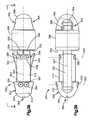
- FIG. 1is a side view of an exemplary embodiment of an implant of the present invention positioned between adjacent spinous processes;
- FIG. 2is a perspective view of an exemplary embodiment of the implant of FIG. 1 in a first configuration
- FIG. 3is a perspective view of an exemplary embodiment of the implant of FIG. 1 in a second configuration
- FIG. 4is a side view of an exemplary embodiment of a retainer of the implant of FIG. 1 ;
- FIG. 5is a top view of an exemplary embodiment of the retainer of FIG. 4 along line 5 - 5 ;
- FIG. 6is an end view an exemplary embodiment of the retainer of FIG. 4 ;
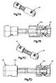
- FIG. 7is a side view showing a partial cross-section of the implant of FIG. 2 ;
- FIG. 7Ais a perspective view of an exemplary embodiment of an alternative implant of the present invention.
- FIG. 7Bis a side view showing a partial cross-section of the implant of FIG. 7A ;
- FIG. 7Cis a perspective view of an exemplary embodiment of another alternative implant of the present invention.
- FIG. 7Dis a side view showing a partial cross-section of the implant of FIG. 7C ;
- FIG. 8is a side view of the implant of FIG. 7 along line 8 - 8 ;
- FIG. 9is a side view showing a partial cross-section of the implant of FIG. 2 with certain portions of the implant not illustrated;
- FIG. 10is a cross-sectional view of an exemplary embodiment of an end portion of the implant of FIG. 2 ;
- FIG. 11is a cross-sectional view of the end portion of FIG. 10 along line 11 - 11 ;
- FIG. 12is a side view of an exemplary embodiment of an inner portion of the implant of FIG. 2 ;
- FIG. 13is an end view of the inner portion of FIG. 12 along line 13 - 13 ;
- FIG. 14is a cross-sectional view of the inner portion of FIG. 12 along line 14 - 14 ;
- FIG. 15is a top view of an exemplary embodiment of a pair of retainers of FIG. 4 ;
- FIG. 16is a partial cross-sectional view of the implant of FIG. 2 ;
- FIG. 17is another cross-sectional view of the implant of FIG. 2 ;
- FIG. 18is a side view of an exemplary actuation mechanism as shown in FIG. 7 ;
- FIG. 19is a cross-sectional view of an exemplary sleeve of the implant of FIG. 2 ;
- FIG. 20is a cross-sectional view of the end portion of FIG. 10 ;
- FIG. 21is a cross-sectional view of the end portion of FIG. 20 along line 21 - 21 ;
- FIG. 22is a side view of an exemplary embodiment of an implant holder of the present invention.
- FIG. 23is a partial cross-sectional view of the implant holder of FIG. 22 along line 23 - 23 ;
- FIG. 24is a side view of an exemplary distal portion of the implant holder of FIG. 22 ;
- FIG. 25is a partial cross-sectional side view of an exemplary embodiment of a guide wire of the present invention.
- FIG. 26is a side view of an exemplary embodiment of a guide wire holder of the present invention.
- FIG. 27is a side view of an exemplary embodiment of an extension for the guide wire FIG. 25 ;
- FIG. 28is a partial cross-sectional side view of an exemplary embodiment of a dilator of the present invention.
- FIG. 29is an enlarged, cross-sectional view of a proximal portion of an assembled guide wire of FIG. 25 , guide wire extension of FIG. 27 , and dilator of FIG. 28 ;
- FIG. 30is a side view of an exemplary embodiment of an insertion device of the present invention.
- FIG. 31is a top view of the insertion device of FIG. 30 along line 31 - 31 ;
- FIG. 32is a perspective view of the insertion device of FIG. 30 ;
- FIG. 33is a side view of exemplary embodiment of another insertion device of the present invention.
- FIG. 34is a top view of the insertion device of FIG. 33 along line 34 - 34 ;
- FIG. 35is a perspective view of the insertion device of FIG. 33 ;
- FIG. 36is a partial side view of an exemplary embodiment of an implant actuation tool of the present invention.
- FIG. 37is a side view of an exemplary embodiment of an implant removal tool of the present invention.
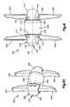
- FIG. 38is a side view of an exemplary embodiment of an alternative implant in a first configuration
- FIG. 39is a top view of the implant of FIG. 38 along line 39 - 39 ;
- FIG. 40is a perspective view of the implant of FIG. 38 in a second configuration
- FIG. 41is a side view of an exemplary embodiment of another alternative implant of the present invention.
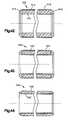
- FIGS. 42-44are cross-sectional views of alternative exemplary embodiments of the sleeves of the implants of FIGS. 2 , 40 and 41 .
- the device 10may include a body portion 12 , a first set of retainers 14 and 16 , and a second set of retainers 18 and 20 .
- the body portion 12may have a sleeve 44 , a first end portion 40 and a second end portion 42 .
- the first and second end portion 40 , 42may be moveable relative to the sleeve 44 . It should, however, be understood that those of ordinary skill in the art will recognize many modifications and substitutions which may be made to various elements of the present invention.
- the device 10may be positioned in between spinous processes of adjacent vertebrae for treating, for example, spinal stenosis.
- the spinous spacer 10may be one member of a set/kit of implants 10 which have different dimensions which takes into account the differing anatomy of patients.
- the device 10is described herein as being used in connection with treating spinal stenosis, one of ordinary skill in the art will readily appreciate that the device may be used in any other part of the body, including specifically the spine where occupying space between portions of the spine and vertebrae may be desirable. Thus, the location and/or surgical procedure is not intended to be limiting in any way.
- the first end portion 40 , second end portion 42 and sleeve 44may be any shape, for example, round, oval or polygonal.
- the retainers 14 , 16 , 18 and 20may be straight, concave, convex or any other shape so long as a vertebral body (e.g. spinous process) may be held be pairs of retainers 14 , 16 and 18 , 20 .
- the body portion 12including the first and second end portions 40 , 42 and sleeve 44 , as well as the retainers 14 , 16 , 18 and/or 20 may be made of any suitable material, preferably biocompatible material, such as metal (e.g., stainless steel, titanium, aluminum, an alloy of two or more metals), plastic, rubber, ceramic, natural body tissue (e.g., bone) or a composite material (i.e., made up of two or more materials).
- metale.g., stainless steel, titanium, aluminum, an alloy of two or more metals
- plastice.g., rubber, ceramic, natural body tissue (e.g., bone) or a composite material (i.e., made up of two or more materials).
- ceramice.g., bone
- a composite materiali.e., made up of two or more materials.
- Various factorsmay be considered when determining the material used to make the elements of the device 10 , including but not limited to, for example, ability to withstand sterilization, ability
- the body portion 12 and/or any other component of the device 10may be radiolucent or radio-opaque.
- radio-opaque markersmay be incorporated into or attached to the body portion 12 or other components. The radio-opaque markers may assist a surgeon in properly aligning the body portion 12 or other components relative to a patient's anatomy.
- each retainer 14 , 16 , 18 and 20may be sized and configured similar to each other and may pass through the sleeve 44 , first portion 40 and second portion 42 .
- each retainer 14 , 16 , 18 and 20may be an elongated structure such as, for examples, a wire 50 .
- the wire 50may have a gauge of between about 0.01 inches and about 0.1 inches.
- the wire 50may have a length of between about 1.0 inch and about 10 inches before being formed into retainer 14 , 16 , 18 and 20 .
- the wire 50may be generally U-shaped with a curved portion 56 and arms 52 , 54 , which may extend from the curved portion 56 .
- the curved portion 56may be curved or bent in more than one plane as illustrated in FIGS. 4 , 5 and 6 .
- the curved portion 56may have a radius of curvature R 1 of, for example, between about 0.1 inches and about 1.0 inch, more preferably, between about 0.1 inches and about 0.5 inches and, most preferably, between about 0.15 inches and about 0.2 inches.
- the curved portion 56may have a radius of curvature R 2 of, for example, between about 0.01 inches and about 1.0 inch, more preferably, between about 0.05 inches and about 0.5 inches and, most preferably, between about 0.05 inches and about 0.1 inches.
- an end 60 of the arm 52may be bent in a first direction at an angle ⁇ (e.g., about 90 degrees) relative to the arm 52 .
- the end 62 of the arm 54may be bent in a second direction, which may be the same or different direction as the first direction and which may be at an angle ⁇ (e.g., about 90 degrees) relative to the arm 54 .
- the end 62may also be bent at an angle ⁇ (e.g., about 15 degrees) ( FIG. 6 ) towards the arm 52 .
- the ends 60 and 62may be bent at angles other than about 90 degrees relative to arms 50 , 52 , respectively, or may have no bend at all.
- End portions 60 and 62 of each retainer 14 , 16 , 18 and 20may be operably connected to an end portion 40 , 42 .
- the curved portions 56 of each retainer 14 , 16 , 18 and 20may be slideably connected to the other end portion 40 , 42 .
- the first end portion 40may comprise an end cap 64 and an inner portion 66 , each of which may have a generally cylindrical configuration and which may be centered on the axis 43 .
- An end 68 of the inner portion 66may be received in a groove 69 within the end cap 64 so that the inner portion 66 and the end cap 64 may be connected together.
- the end 68may have a conical configuration; however, those skilled in the art will appreciate than another other shape may be used so long as the end 68 may be held in the end cap 64 .
- the end cap 64may have first and second cam surfaces 70 , and first and second teeth 72 proximate the cam surfaces 70 .
- the cam surfaces 70may have an angle ⁇ of, for example, between about 90 degrees and about 160 degrees, more preferably, between about 100 degrees and about 135 degrees and, most preferably, between about 105 degrees and about 115 degrees.
- the teeth 72 and cam surfaces 70may be located within diametrically opposed openings 73 in the end cap 64 .
- the inner portion 66may have a first and second upper slot 76 , 78 , respectively.
- a notch 80 at the end of the first upper slot 76may extend at an angle ⁇ (e.g., about 90 degrees) relative to the slot 76 (e.g., a downward angle) and a notch 82 at the end of the second upper slot 78 may extends at an angle ⁇ (e.g., about 15 degrees) relative to the slot 78 (e.g., upward and toward the first upper slot 76 ).
- the angle of the notch 80 relative to the slots 76may correspond to the angle ⁇ of end 60 of the retainers 14 , 16 , 18 and 20 .
- the angle of the notch 82 relative to the slots 78may correspond to the angle ⁇ of the end 62 of the retainers 14 , 16 , 18 and 20 .
- the inner portion 66may also have first and second lower slots 84 and 86 , which may have notches 88 and 90 , respectively.
- the notch 88 at the end of the first lower slot 84may extend at an angle ⁇ (e.g., about 15 degrees) relative to the slot 84 (e.g., notch 88 may be angled downward and away from the second lower slot 86 ) and the notch 90 at the end of the lower slot 86 may extends at an angle ⁇ (e.g., about 90 degrees) relative to the slot 86 (e.g., an upward angle).
- the angle of the notch 88 relative to the slots 84may correspond to the angle ⁇ of the end 62 of the retainers 14 , 16 , 18 and 20 .
- the angle of the notch 90 relative to the slots 86may correspond to the angle ⁇ of end 60 of the retainers 14 , 16 , 18 and 20 .
- the retainers 14 and 16may be positioned beside each other and generally inside the body portion 12 when in the deployed or undeployed position.
- the arms 52 and 54 of the retainers 14 and 16may be received in the first and second upper slots 76 and 78 in the inner portion 66 of the first end portion 40 .
- the ends 60 and 62 ( FIG. 17 ) of the retainer 14may be received in the notches 80 and 82 , respectively, at the ends of the first and second upper slots 76 and 78 , respectively, of the first end portion 40 such that the retainer 14 may be fixed with respect to the first end portion 40 .
- the curved portion 56 of the retainer 16may be positioned adjacent the cam surface 70 ( FIG. 7 ) on the end cap 64 of the first end portion 40 , and may be positioned around the tooth 72 such that the retainer 16 may slide with respect to the end cap 64 of the first end portion 40 .
- the arms 52 and 54 of the retainers 14 and 16may also be received in the first and second upper slots 76 and 78 in an inner portion 66 of the second end portion 42 .
- the ends 60 and 62 of the retainer 16may be received in the notches 80 and 82 , respectively, at the ends of the first and second upper slots 76 and 78 , respectively, of the second end portion 42 such that the retainer 16 may be fixed with respect to the second end portion 42 .
- the curved portion 56 of the retainer 14may be positioned adjacent the cam surface 70 on the end cap 64 of the second end portion 42 , and may be positioned around the tooth 72 such that the retainer 14 may slide with respect to the end cap 64 of the second end portion 42 .
- the retainers 18 and 20may be positioned beside each other and generally inside the body portion 12 when in the deployed or undeployed position.
- the arms 52 and 54 of the retainers 18 and 20may be received in the first and second lower slots 84 and 86 in the inner portion 66 of the first end portion 40 .
- the ends 60 and 62 ( FIG. 17 ) of the retainer 18may be received in the notches 90 and 88 , respectively, at the ends of the first and second lower slots 86 and 84 , respectively, of the first end portion 40 such that the retainer 18 may be fixed with respect to the first end portion 40 .
- the curved portion 56 of the retainer 20may be positioned adjacent the cam surface 70 ( FIG.
- the arms 52 and 54 of the retainers 18 and 20may also be received in the first and second lower slots 84 and 86 in an inner portion 66 of the second end portion 42 .
- the ends 60 and 62 of the retainer 16may be received in the notches 90 and 88 , respectively, at the ends of the first and second lower slots 86 and 84 , respectively, of the second end portion 42 such that the retainer 20 may be fixed with respect to the second end portion 42 .
- the curved portion 56 of the retainer 18may be positioned adjacent the cam surface 70 on the end cap 64 of the second end portion 42 , and may be positioned around the tooth 72 such that the retainer 18 may slide with respect to the end cap 64 of the second end portion 42 .
- the end cap 64 and inner portion 66 of the second end portion 42may be identical to the end cap 64 and inner portion 66 of the first end portion 40 .
- the retainers 14 and 16generally may be positioned beside each other.
- the arms 52 and 54 of the retainers 14 and 16may be received in the first and second upper slots 76 and 78 in the inner portion 66 .
- the ends 60 and 62 ( FIG. 17 ) of the retainer 16may be received in the notches 80 and 82 , respectively, at the ends of the first and second upper slots 76 and 78 , respectively.
- the curved portion 56 of the retainer 14may be positioned adjacent the cam surface 70 ( FIG.
- the retainers 18 and 20generally may be positioned beside each other in the body portion 12 .
- the arms 52 and 54 of the retainers 18 and 20may be received in the first and second lower slots 84 and 86 in the inner portion 66 .
- the ends 60 and 62 of the retainer 20may be received in the notches 90 and 88 , respectively, at the ends of the first and second lower slots 86 and 84 , respectively.
- the curved portion 56 of the retainer 18may be positioned adjacent the cam surface 70 on the end cap 64 , and may be positioned around the tooth 72 .
- a connector 100may extend along the axis 43 between the end portions 40 and 42 of the body portion 12 . As shown in FIG. 18 , the connector 100 may have external screw-threads and may have sections 102 , 104 . Each section 102 and 104 may have a recess 105 for receiving an actuation tool (e.g., actuation tool 184 of FIG. 36 ). The recess 105 may have gripping surfaces for engaging corresponding gripping surfaces on an actuation tool (e.g., the recess 105 may be polygonal in shape).
- the sections 102 and 104also have respective screw threads 106 and 108 which may extend around the connector 100 in opposite directions relative to each other (e.g., section 102 may have right handed threads 106 ; section 104 may have left handed threads 108 ). As shown in FIGS. 7 and 9 , the screw threads 106 and 108 on the connector 100 may engage corresponding internal screw threads 114 on the inner portions 66 of end portions 40 and 42 of the body portion 12 . Such a configuration may enable the end portions 40 and 42 to move along the connector 100 axially toward each other upon rotation of the connector 100 relative to the inner portions 66 .
- the retainers 14 , 16 , 18 and 20may move with respect to the end portions 40 , 42 .
- the retainers 14 , 16 , 18 and 20may move with the end caps 64 and inner portions 66 to which the ends 60 , 62 of the retainers 14 , 16 , 18 and 20 may be attached.
- the retainers 14 and 18which may be fixed in the end cap 64 of the first end portion 40 may also move so that the curved portions 56 of the retainers 14 and 18 may be pushed forcefully against the cam surfaces 70 on the end cap 64 of the second end portion 42 .
- the retainers 16 and 20which may be fixed in the end cap 64 of the second end portion 42 may also move so that the curved portions 56 of the retainers 16 and 20 may be pushed forcefully against the cam surfaces 70 on the end cap 64 of the first end portion 42 .
- the cam surfaces 70may guide the curved surfaces 56 so that the retainers 16 and 20 may move outward through the openings 73 in the end cap 64 of the first end portion 40 and the retainers 14 and 18 may move outward through the openings 73 in the end cap 64 of the second end portion 42 .
- the arms 52 and 54 of the retainer wires 50may also move outward through the openings 73 as the end portions 40 and 42 of the body structure 12 continue to move axially toward each other.
- the arms 52 and 54may be deflected (e.g., along an arcuate or straight path) as the arms 52 and 54 slide outward against the cam surfaces 70 .
- the retainers 14 , 16 , 18 and 20may be pre-bent so that they resume the bent configuration once extended from the ends 40 , 42 (e.g., the retainers 14 , 16 , 18 and 20 may have a shape memory).
- the retainers 14 , 16 , 18 and 20may be deformed (elastically or plastically) as the retainers 14 , 16 , 18 and 20 move out of the body portion 12 .
- the retainers 14 , 16 , 18 and 20When the retainers 14 , 16 , 18 and 20 extend out of the end portions 40 , 42 , the retainers 14 , 16 , 18 and 20 may be positioned around adjacent spinous processes in the deployed position, and the retainers 14 , 16 , 18 and 20 may help to hold the device in position between adjacent spinous processes as shown in FIG. 1 .
- the retainers 14 , 16 , 18 and 20In a deployed position, the retainers 14 , 16 , 18 and 20 may extend away from the body a length L 1 ( FIG. 1 ) which may be, for example, between about 0.2 inches and 2.0 inches, more preferably, between about 0.3 inches and 1.0 inch and, most preferably, between about 0.4 inches and about 0.6 inches.
- the retainers 14 and 16 , 18 and 20may have a dimension D 2 ( FIG. 1 ) between adjacent retainers 14 and 16 , 18 and 20 which may be substantially the same as the length L 2 of the sleeve 44 ( FIG. 19 ).
- the dimension D 2may be at least, for example, between about 0.1 inch and 2.0 inches, more preferably, between about 0.2 inches and 1.0 inches and, most preferably, between about 0.4 inches and about 0.5 inches.
- retainers 14 , 16 , 18 and 20may be retracted into the body portion 12 .
- the sleeve 44may also help to hold the body portion 12 in position between adjacent spinous processes as shown in FIG. 1 .
- the sleeve 44may be freely movable axially and rotationally relative to the other parts of the implant 10 (e.g., the end portions 40 , 42 and retainers 14 , 16 , 18 and 20 ).
- the sleeve 44may be captured between the end portions 40 and 42 and may be prevented from moving axially about axis 43 .
- the sleeve 44may be fixed with respect to the connector 100 such that the sleeve 44 may not move axially relative to the connector 100 .
- the sleeve 44may, however, be free to rotate relative to the end portions 40 and 42 as well as the retainers 14 , 16 , 18 and 20 . If bending or other movement of the spine causes the spinous processes 24 and 26 to impart rotational forces to the sleeve 44 , those forces may be dissipated by rotation of the sleeve 44 relative to the other parts of the implant 10 . Such a construction may prevent the transmission of rotational forces from the sleeve 44 to the retainers 14 , 16 , 18 and 20 and, thereby, may help prevent unwanted rotation and/or displacement of the retainers 14 , 16 , 18 and 20 .
- the sleeve 44may have an outer surface 120 with a diameter D, which may be uniform along the length of the sleeve 44 (e.g., the sleeve may have a cylindrical contour).
- the diametermay be between about 0.1 inches and about 1.0 inches, more preferably, between about 0.15 inches and about 0.8 inches and, most preferably, between about 0.235 inches and about 0.63 inches.
- the end caps 64 of the end portions 40 , 42may have diameters which may be substantially similar to the diameter D.
- An inner surface 122 of the sleeve 44may have a contour (e.g., convex contour) which may be curved radially outward.
- the inner surface 122may define a tapered central section 124 of the sleeve 44 which may be thinner than the sections 126 at opposite ends of the sleeve 44 .
- the sleevemay have a thickness T, for example, between about 0.01 inches and about 0.15 inches, more preferably, between about 0.02 inches and about 0.07 inches and, most preferably, between about 0.035 inches and about 0.05 inches.
- Tthickness
- Such a constructionmay provide greater flexibility to the sleeve 44 at the central section 126 so that the sleeve 44 may be deflected radially inward under forces applied from the spinous processes 24 and 26 .
- a sleeve 44may be unnecessary.
- the first end portion 40may have an extended wall portion 40 a .
- the extended wall 40 amay be positioned between adjacent spinous processes.
- the first end portion 40 and second end portion 42may have extended wall portions 40 a and 42 a , respectively.
- the extended walls portions 40 a , 42 amay be positioned between the adjacent spinous processes.
- the body portion 12may be inserted in the space 23 between the spinous processes 24 and 26 of adjacent vertebrae 28 and 30 (shown schematically).
- the body portion 12may have a first, expanded configuration such as shown in FIG. 2 .
- the bodymay have a length L ( FIG. 7 ) of, for example, between about 0.15 inches and about 5.0 inches, more preferably, between about 0.5 inches and about 2.0 inches and, most preferably, between about 1.2 inches and about 1.4 inches.
- end portions 40 and 42 of the body structure 12may be spaced apart from each other along a longitudinal central axis 43 .
- the sleeve 44may be positioned between the end portions 40 and 42 .
- the retainers 14 , 16 and 18 , 20may be located in a retracted or undeployed position such that the retainers 14 , 16 and 18 , 20 generally may be positioned within the body portion 12 .
- Such a constructionmay enable the body portion to be inserted in between the spinous processes 24 and 26 from the side of the spine.
- the body portion 12may be moved to a second, contracted configuration such as shown in FIG. 3 .
- the end portions 40 and 42may be moved axially toward each other.
- the body 12may have a length L ( FIG.
- the retainers 14 , 16 , 18 and 20may be moved out of the body 12 from the retracted position to the deployed position of FIG. 3 .
- the retainers 14 and 16may extend away from the body portion 12 and may be positioned on opposite sides of the spinous process 24 on the vertebrae 28 .
- the retainers 18 and 20may extend away from the body portion 12 and may be positioned on opposite sides of the spinous process 26 on the vertebrae 30 .
- the body portion 12may help maintain a desired spacing between the adjacent spinous processes 24 and 26 .
- the retainers 14 , 16 , 18 and 20may help to hold the body portion 12 in place with respect to the spine and/or surrounding soft tissue.
- Various instrumentsmay be used for insertion and/or removal of the implants 10 such as, for example, an implant holder 140 , guide wire 170 , dilator 176 , insertion tubes 180 , 182 , actuation tool 184 and removal tool 290 . While the instruments described below may be used with the implant 10 , one of ordinary skill in the art will readily appreciate that any number of instruments may be used in place of those described herein.
- the implant holder 140 of FIGS. 22-24may include an elongated stem 142 and a handle 144 .
- the elongated stem 142may be hollow (e.g., tubular) and may extend from the handle 144 and has a distal end 143 .
- a wheel 148may be positioned on the handle 144 .
- a shaft 146which may also be hollow, may extend through the stem 142 , and may be operably connected to the wheel 148 so that rotation of the wheel 148 may result in rotation of the shaft 146 relative to the stem 142 .
- the distal end 143 of the shaft 146may protrude from an open end 150 of the stem 142 and may have a screw-thread 152 .
- a pair of protrusions 154which may be diametrically opposed to each other (one of which is shown in FIG. 24 ), may project axially outward from the open end 150 of the stem 142 proximate the shaft 146 . It should be noted that in some embodiments, one or more protrusions 154 may be used.
- the implant inserter 140may engage the first or second end portions 40 , 42 and may be used as an insertion tool for moving the implant 10 into its installed position from the side of the spine.
- the end caps 64 of the first and/or second end portions 40 , 42may have a pair of slots 130 at an outer end 132 .
- the end portions 40 , 42may have one or more slots 130 , which may be engaged by one or more protrusions 154 of the stem 142 .
- the first and/or second end portions 40 , 42may have an internal screw thread 134 which may extends axially inward from the outer end 132 .
- the screw-thread 152 of the shaft 146may engage the screw thread 134 of the first or second end portions 40 , 42 . Thereafter, the wheel 148 may be rotated to draw the holder 140 and, consequently, the protrusion(s) 154 of the holder 140 towards the first or second end portions 40 , 42 so that the protrusion(s) 154 may be inserted into the slot(s) 130 of the first or second end portions 40 , 42 .
- the construction of the end portions 40 , 42 and the holder 140may prevent the end portions 40 , 42 and retainers 14 , 16 18 and 20 from rotating relative to the holder 140 about the axis 43 .
- the spinous spacer 10may be inserted into the body using, for example, a lateral approach to the spine.
- An incisionmay be made in a patient's side.
- a guide wire 170such as shown in FIG. 25 , may be inserted through the incision.
- a distal end 194 of the guide wire 170may be sharpened to assist the guide wire 170 in penetrating soft tissue.
- a proximal end 190 of the guide wire 170may have an engagement portion such as, for example, an inner screw-threaded counterbore 192 .
- a surgeonmay grasp the guide wire 170 directly or may use a holder 172 to hold the guide wire 170 .
- the holder 172may have a handle 172 , a passage 195 , and a tightening member, such as a screw 196 , intersecting the passage 195 .
- the guide wire 170may be clamped in place in the passage 195 by tightening the screw 196 .
- the guide wire 170may be attached to the holder 172 before or after the guide wire 170 is inserted into the body. In many cases, the guide wire 170 may be long enough for a surgeon to extend the distal end 194 of the guide wire 170 into the space 23 between the adjacent spinous processes 24 and 26 . However, in some cases a surgeon may have to extend the length of the guide wire 170 using an extension 174 .
- the extension 174may be an elongated member (e.g., rod or bar) having a distal end 200 and a proximal end 202 .
- the distal end 204may have a engagement portion 204 , which may be in the form of screw threads.
- the distal end 204may have a reduced diameter as compared to the rest of the extension 174 .
- the engagement portion 204 of the extension 174may be screwed into the counterbore 192 in the proximal portion 190 of the guide wire 170 .
- a dilator 176may be positioned over the guide wire 170 and/or extension 174 (if used), and may be moved toward the spine by sliding the dilator 176 along the guide wire 170 and/or extension 174 .
- the dilator 176may be a hollow tubular structure with a passage 205 therethrough.
- the distal end 208 of the dilator 176may have a tapered surface 206 . As the tapered surface 206 of the dilator 176 moves toward and into the space 23 between the spinous processes 22 and 24 , the tapered end 206 may dilate the soft tissue.
- a pin 210may extend into the passage 205 near the proximal end 212 .
- the dilator 176may be positioned and moved over the guide wire 170 and/or extension 174 until the pin 210 engages the proximal end 190 of the guide wire 170 and/or proximal end 202 of the extension 174 .
- the length of the dilator 176may be correlated to the length of the guide wire 170 such that the pin 210 on the dilator 176 may abutment the proximal end 190 of the guide wire 170 to prevent movement of the dilator 176 once the tapered surface 206 reaches the space 23 between the spinous processes 24 and 26 .
- one or more sequential dilatorsmay be placed over the dilator 176 and may be used to dilate the opening through tissue from the skin to the vertebrae.
- tubes 180 and 182may be positioned over the dilator 176 .
- the tubes 180 , 182may be part of a set of tubes which differ in size (e.g., diameter/dimension) to accommodate different patient anatomies.
- the diameter/dimension of the tubesmay be between about 0.1 inches and about 1.0 inches, more preferably, between about 0.15 inches and about 0.8 inches and, most preferably, between about 0.25 inches and about 0.65 inches.
- the tubemay be used to distract tissue as well as the space in between the spinous processes of adjacent vertebrae.
- the tube 180 of FIGS. 30-32may have a configuration similar to the tube 182 of FIGS. 33-35 .
- Tube 180may have a smaller diameter and may be shorter than tube 182 .
- All tubes in the set of tubes, including tubes 180 , 182may be cylindrical and each tube with a larger diameter may be sized to fit closely over the tube with the next smallest diameter. In this way, all of the tubes in the set may be nested concentrically together.
- certain tubesmay correspond to the different sized devices 10 . These tubes may be configured such that the tube has an inner diameter closely matching the outer diameter D of the spinous spacer 10 . Such a construction may enable a device 10 to slide closely and smoothly through its corresponding tube when the spinous spacer 10 is in the extended configuration of FIG. 2 .
- the tubesmay also have two slots 260 which may enable retainers 14 , 16 , 18 and 20 to be deployed through the tube as described below. In other embodiment the tubes may have one slot 260 .
- the surgeonmay first select a tube having a first dimension D 1 , such as, for example, the tube 180 shown in FIG. 30 .
- tube 180may have a tapered distal end 220 .
- the surgeonmay move the tube 180 over the guide wire 170 and/or dilator 176 (i.e., the assembly of FIG. 29 ) so that the tube 180 may move along the dilator 176 toward the distal end 208 of the dilator 176 .
- the tapered distal portion 220 of the tube 180is moved into the space 23 between the spinous processes 24 and 26 , it may dilate the soft tissue as well as distract the spinous processes 24 and 26 .
- the tubesmay have at least one pair of indication slots 266 .
- the indication slots 266may be spaced axially from the distal end 262 of the tubes and may be diametrically opposed to each other. When looking at the tubes 180 , 182 from the view shown in FIGS. 30 and 33 , the indication slots 266 may overlap each other and may be oriented at an angle with respect to each other.
- the indication slots 266may be at a 90 degree angle to each other so that their overlapping x-ray image may form an “X” when the tube is viewed in the orientation shown in FIG. 30 or 33 .
- Such a configurationmay be used to produce shapes when viewing an x-rays.
- another pair of indication slots 268may be provided on tube 180 , 182 more proximal than slots 266 .
- the pairs of indication slots 266 and 268may enable a surgeon to rotate the tube until the “X” images are formed in an x-ray view from the rear of the spine. Once the “X” image is visible, this may indicate that the tube and, in particular, the slots 266 are correctly oriented for deployment of the retainers 14 , 16 , 18 and 20 therethrough.
- each tubemay have a knob 222 at its proximal end 224 which may project inwardly in the passage through the tube.
- the knob 222 on the larger tubemay move into abutment with the distal most end 224 of the smaller tube.
- Such a constructionmay limit movement of larger tubes over small tubes so that the tapered distal end 220 of the concentric tubes overlap at the same location between the spinous processes 24 and 26 .
- Each tubemay also have a pair of slots 230 at its proximal end 224 .
- the slots 230may delineate an opposed pair of sections 232 , which may be deflectable.
- the section 232may be axially aligned with the knob 222 but may be spaced a short distance axially from the knob 222 .
- a surgeonmay push the proximal end 224 at a location 224 a opposite the knob 222 (e.g., at a location approximately 180 degrees from the knob) in a direction towards the knob 222 (e.g., in a direction perpendicular to the longitudinal axis of the outermost tube 182 ).
- the slots 230may enable the proximal end 224 of the tube 182 , including the knob 222 and sections 232 , to be deflected upward as shown in FIG. 30 so that the concentric inner tubes can be removed together from the outermost tube 182 .
- the guide wire 174 and the dilator 176may also be removed from the outermost tube 182 .
- the surgeonmay select a device 10 of a size corresponding to the inner dimension of the outermost tube 182 . A surgeon may then attach the selected device 10 to the implant holder 140 , and may move the device 10 through the tube 182 towards and in between the spinous processes 24 and 26 .
- the implant holder 140may be inserted into the tube 182 until the proximal most portion 224 of the outermost tube engages a stepped portion 250 ( FIGS. 22 and 23 ) of the holder 140 .
- the stepped portion 250may have dimensions so that each step matches the inner diameters of a tube in the set of tubes (e.g., tubes 180 , 182 ).
- Each step 250may also have a notch 252 to receive the knob 222 on the corresponding tube.
- Such a constructionmay assist in positioning the implant in the proper location between adjacent spinous processes 24 , 26 (i.e., the stepped portion 250 may act as a stop, which may prevent the device 10 from being inserted too far through the tube) as well as aligning the retainers 14 , 16 , 18 and 20 with the slots 260 (i.e., positioning the knob 222 in the notch 252 may prevent rotational misalignment).
- the actuation tool 184 shown in FIG. 36may be inserted through the hollow shaft 146 on the holder 140 .
- the holder 140 , actuation tool 184 and device 10may be attached together before placement in the body and inserted into the body as a single unit.
- the tool 184may be inserted through the holder 140 until an engagement portion 254 of the tool 184 is received in the recess 105 of the connector 100 .
- the tool 184may then be rotated while the holder 140 is held in position.
- the tool 184may cause the connector 100 to rotate and the holder 140 may prevent rotational movement of the end portions 40 , 42 .
- the end portions 40 , 42may move axially along the axis 43 towards each other.
- the retainers 14 , 16 , 18 and 20may be deployed from the body portion 12 and may be positioned around adjacent spinous processes 24 , 26 . It should be noted that the end portions 40 , 42 may move towards each other until the retainers 14 , 16 , 18 and 20 tightly grip or firmly engage the spinous processes, thereby holding the device 10 in place.
- the distance between the end portions 40 , 42 when the retainers 14 , 16 , 18 and 20 are in the fully deployed positionmay depend on the length L 1 of the retainers 14 , 16 , 18 and 20 when at least a portion of the retainers 14 , 16 , 18 and 20 engage the spinous processes.
- the length L 1 of the retainers 14 , 16 , 18 and 20may depend on the width W ( FIG. 1 ) of the spinous processes.
- the retainers 14 , 16 , 18 and 20may be deployed from the body portion 12 outwardly through the slots 260 of the tubes.
- the slots 260may extend axially from the distal most end 262 of each tube towards the proximal end 224 .
- the slots 260may be diametrically opposed to each other and may be configured so that the tube 182 may be moved over the device 10 (e.g., slide on and off the device 10 ) after the retainers 14 , 16 , 18 and 20 have been deployed around the spinous processes.
- a pair of slots 270 near the proximal end 224 of the tubesmay serve as viewing windows, which may enable an operator to align the slots 260 (and thereby the retainers 14 , 16 , 18 and 20 ) in the cranio-caudal direction.
- the tool 184may be withdrawn from the holder.
- the holder 140may be detached from the device 10 by rotating the wheel 148 . Thereafter, the holder 140 may be withdrawn from the tube 182 .
- the tube 182may then be removed from the patient, leaving the device 10 in between the adjacent spinous processes 24 , 26 .
- a removal tool 290may be used to retract retainers 14 , 16 , 18 and 20 into the body portion 12 and remove the device 10 from the body.
- the removal tool 280may be a elongated member (e.g., rod) having a proximal end 292 and two distinct engagement portions 294 and 296 .
- the proximal portion 292may be sized and configured for engagement with a handle, drill or some other device which may impart rotation motion.
- the first engagement portion 296may have a screw thread 298 so that the tool 290 may be inserted into the open outer end 132 ( FIG. 21 ) of the end portion 64 .
- the second engagement portion 294may be sized and configured (e.g., may have a polygonal or hex shape) to engage the recess 105 ( FIG. 18 ) of the connector 100 .
- a surgeonmay use a lateral approach to the spine.
- An incisionmay be made in the side of a patient and the tool 290 may be inserted into the body until the second engagement portion 294 of the tool 290 may be inserted in the recess 105 .
- the tool 290may be used in place of the guide wire 170 and/or the extension 174 .
- a dilator 176may be inserted over the tool 290 .
- Sequentially larger tubes 180 , 182 , etc.may be inserted over dilator 176 and into the space 23 between the adjacent spinous processes 24 and 26 . When dilation and distraction are completed by placement of an outermost tube 182 , the smaller tubes and/or dilator 176 may be removed from the tube 182 .
- the tool 290 and the connector 100may then be rotated to drive the end portions 40 and 42 of the body portion 12 axially away from each other.
- the retainers 14 , 16 , 18 and 20may be drawn back into the body portion 12 from the deployed positions to the retracted positions.
- the screw thread 298 of the first engagement portion 296may engage the internal screw thread 114 ( FIGS. 7 and 9 ) of the inner portion 66 of the end portion 42 .
- Such a configurationmay cause the tool 290 to engage the device 10 in a manner similar to attachment of the implant holder 140 .
- the rod 290may then be used to pull the spinous spacer 10 through the tube 182 .
- FIGS. 38-40illustrate another embodiment of an implant for treating spinal stenosis.
- the device 300may be part of set of implants which may have different sizes to accommodate different anatomies.
- the body portions 302may be configured for installation between a pair of adjacent spinal processes 24 and 26 ( FIG. 1 ) by use of the installation devices described above.
- the body structure 302may have first and second end portions 304 and 306 , which may be centered on a longitudinal axis 307 .
- a sleeve 308may be freely movable axially and rotationally between the two end portions 304 and 306 of the body portion 302 .
- the first end portion 304may have a base 310 , which may be generally dome-shaped.
- a stem 312may project axially from the base 310 .
- the stem 312may be any shape, for example, cylindrical.
- a first hinge 320may operably connect a first retainer 322 to the base 310 .
- the hinge 320may have a pivotal axis 323 , which may be perpendicular to the longitudinal axis 307 of the body portion 302 .
- First hinge 320may comprise a pin about which the first retainer 322 may pivot or rotate.
- a second retainer 326may be operably connected to the stem 312 by a second hinge 328 , which may have a pivotal axis 329 which may be parallel to the first pivotal axis 323 .
- Second hinge 328may comprise a pin about which the second retainer 326 may pivot or rotate.
- a third and fourth retainer 340 and 342may be operably connected to the base 310 and the stem 312 , respectively, by a third and fourth hinge 344 and 346 , respectively.
- the hinges 344 and 346may have axes 347 and 349 , respectively, which may be parallel to each other.
- the device 300may have an internal connector (not shown) which may be substantially similar to the connector 100 of the device 10 . Accordingly, the connector of the implant 300 may have two sections with screw threads in opposite directions and each section may engage an end portion 304 and 306 . Rotation of the connector about axis 307 may result in the end portions 304 moving axially toward each other. An opening 350 in the first end portion 302 may provide access for an actuation tool (e.g. screwdriver) to engage the connector such that the body portion 302 may be moved from the extended configuration of FIGS. 38 and 39 to the contracted configuration of FIG. 40 .
- an actuation toole.g. screwdriver
- the first retainer 322 and the third retainer 340may contact surface 352 of the sleeve 308 , and the sleeve 308 as it moves will push the first and third retainers 322 , 240 outwardly away from axis 307 .
- the second retainer 326 and the fourth retainer 342may move or be pushed against cam surfaces 354 , which may be positioned within openings 355 of the second end portion 306 . In this way, the retainers 326 and 342 may move outwardly from the axis 307 .
- the retainers 322 , 326 , 340 and 342may thus be moved pivotally from retracted positions to deployed positions such that the retainers 322 , 326 , 340 and 342 may be positioned on opposite sides of the adjacent spinous processes 24 and 26 .
- the sleeve 308may be able to rotate and/or deflect under forces applied from the spinous processes 24 and 26 in the same manner as the sleeve 44 shown in FIG. 1 .
- FIG. 41illustrates yet another embodiment of a device for treating spinal stenosis.
- the device 400may have a body portion 432 and upper retainers 402 , 404 and lower retainers 406 , 408 .
- the body portion 432may have first and second end portions 410 , 412 and a sleeve 450 positioned therebetween.
- the upper retainers 402 and 404may be pivotally connected by hinges 414 and 416 , respectively, on the first and second end portions 410 and 412 .
- the hinges 414 and 416may have pivotal axes 417 and 419 , respectively, which may be parallel to each other.
- the lower retainers 406 and 408may be pivotally connected by hinges 424 and 426 , respectively, on first and second end portions 410 and 412 .
- the hinges 424 and 426may have pivotal axes 427 and 429 which are parallel to each other and parallel to the pivotal axes 417 and 419 . All four pivotal axes 417 , 419 , 427 and 429 may be perpendicular to the longitudinal central axis 431 of the body portion 432 .
- a body portion 432 of a selected sizemay be installed between the adjacent spinous processes 24 and 26 ( FIG. 1 ) using the installation devices described above.
- an actuation toole.g., screwdriver
- the connector of FIG. 41may be rotated in order to draw the two end portions 410 and 412 axially together.
- the retainers 402 , 404 , 406 and 408may be positioned substantially parallel to the axis 431 .
- the retainers 402 , 404 , 406 and 408may be moved against surfaces 446 at the opposite ends of the sleeve 450 . As shown in FIG. 41 , this may cause the retainers 402 , 404 , 406 and 408 to pivot from retracted positions to deployed positions in which the retainers 402 , 404 , 406 and 408 may extend outward from the axis 431 and body portion 432 . In the contracted configuration, the retainers 402 , 404 , 406 and 408 may deploy and hold the device 400 within the space 23 between the adjacent spinous processes 24 and 26 . Moreover, the sleeve 450 may be able to rotate and/or deflect relative to the other parts of the device 400 (e.g., end portions 410 , 412 ) under forces applied from the adjacent spinous processes 24 and 26 .
- FIGS. 42 , 43 and 44illustrate alternative embodiments of sleeves 44 , 308 , and 450 described above.
- sleeve 500may have an inner and outer component 510 and 512 .
- the outer component 512may have end portions 514 and 516 .
- a wall portion 518which may be cylindrical, may extend axially between the end portions 514 and 516 .
- the inner component 510may be captured axially and rotationally within the outer component 512 .
- the inner componentmay consist of a wall, which also may be cylindrical, with a thickness which may be substantially greater than the thickness of the surrounding wall portion 518 of the outer component 512 .
- the inner component 510 of the sleeve 500may be formed of a material with different properties than the material used to form the outer component 512 .
- the inner component 510may be formed of a material with a lower modulus of elasticity than the outer component 512 .
- Using a more rigid material for the outer component 512may result in the sleeve 500 being more resistant to wear under the influence of the adjacent spinous processes 24 and 26 ( FIG. 1 ).
- making the inner component 510 of a softer materialmay enable the sleeve 500 to be more flexible than if the sleeve 500 was formed entirely of a rigid material, similar to the material which may be used to make the outer component 512 .
- the inner and outer components 510 , 512may be made of any suitable material, preferably biocompatible material, such as metal (e.g., stainless steel, titanium, aluminum, an alloy of two or more metals), plastic, rubber, ceramic, natural body tissue (e.g., bone) or a composite material (i.e., made up of two or more materials).
- the outer component 512 of the sleevemay be made of polycarbonate, which may have a higher modulus of elasticity than polycarbonate urethane which may be used to make inner component 510 .
- the sleeve 502may have a component 530 formed of the softer, more flexible material which may be contained entirely within the surrounding structure of the component 532 .
- the component 532may be formed of the more rigid material than the material of component 530 .
- the outer component 540may be made of a material which may have a lower modulus of elasticity than the material of the inner component 542 . The softer outer material may results in less wear to adjacent spinous processes 24 and 26 positioned against the sleeve 504 .
Landscapes
- Health & Medical Sciences (AREA)
- Orthopedic Medicine & Surgery (AREA)
- Life Sciences & Earth Sciences (AREA)
- Neurology (AREA)
- Surgery (AREA)
- Heart & Thoracic Surgery (AREA)
- Engineering & Computer Science (AREA)
- Biomedical Technology (AREA)
- Nuclear Medicine, Radiotherapy & Molecular Imaging (AREA)
- Medical Informatics (AREA)
- Molecular Biology (AREA)
- Animal Behavior & Ethology (AREA)
- General Health & Medical Sciences (AREA)
- Public Health (AREA)
- Veterinary Medicine (AREA)
- Prostheses (AREA)
Abstract
Description
Claims (17)
Priority Applications (11)
| Application Number | Priority Date | Filing Date | Title |
|---|---|---|---|
| US11/198,393US7753938B2 (en) | 2005-08-05 | 2005-08-05 | Apparatus for treating spinal stenosis |
| BRPI0614139-0ABRPI0614139A2 (en) | 2005-08-05 | 2006-08-03 | apparatus for insertion between the spinous processes of two adjacent vertebrae through a lateral opening in a minimally invasive proposal to treat spinal stenosis, and spinal implant |
| JP2008525260AJP4850907B2 (en) | 2005-08-05 | 2006-08-03 | Device for treating spinal stenosis |
| PL06813303TPL1945117T3 (en) | 2005-08-05 | 2006-08-03 | Apparatus for treating spinal stenosis |
| ES06813303TES2394099T3 (en) | 2005-08-05 | 2006-08-03 | Apparatus for the treatment of spinal stenosis |
| CA2617545ACA2617545C (en) | 2005-08-05 | 2006-08-03 | Apparatus for treating spinal stenosis |
| PCT/US2006/030614WO2007019391A2 (en) | 2005-08-05 | 2006-08-03 | Apparatus for treating spinal stenosis |
| EP06813303AEP1945117B1 (en) | 2005-08-05 | 2006-08-03 | Apparatus for treating spinal stenosis |
| US11/997,880US8870890B2 (en) | 2005-08-05 | 2006-08-03 | Pronged holder for treating spinal stenosis |
| AU2006278462AAU2006278462A1 (en) | 2005-08-05 | 2006-08-03 | Apparatus for treating spinal stenosis |
| TW095128763ATW200738210A (en) | 2005-08-05 | 2006-08-04 | Apparatus for treating spinal stenosis |
Applications Claiming Priority (2)
| Application Number | Priority Date | Filing Date | Title |
|---|---|---|---|
| US11/198,393US7753938B2 (en) | 2005-08-05 | 2005-08-05 | Apparatus for treating spinal stenosis |
| US79588306P | 2006-04-27 | 2006-04-27 |
Related Child Applications (1)
| Application Number | Title | Priority Date | Filing Date |
|---|---|---|---|
| US11/997,880Continuation-In-PartUS8870890B2 (en) | 2005-08-05 | 2006-08-03 | Pronged holder for treating spinal stenosis |
Publications (2)
| Publication Number | Publication Date |
|---|---|
| US20070032790A1 US20070032790A1 (en) | 2007-02-08 |
| US7753938B2true US7753938B2 (en) | 2010-07-13 |
Family
ID=37453031
Family Applications (1)
| Application Number | Title | Priority Date | Filing Date |
|---|---|---|---|
| US11/198,393Active2026-05-17US7753938B2 (en) | 2005-08-05 | 2005-08-05 | Apparatus for treating spinal stenosis |
Country Status (10)
| Country | Link |
|---|---|
| US (1) | US7753938B2 (en) |
| EP (1) | EP1945117B1 (en) |
| JP (1) | JP4850907B2 (en) |
| AU (1) | AU2006278462A1 (en) |
| BR (1) | BRPI0614139A2 (en) |
| CA (1) | CA2617545C (en) |
| ES (1) | ES2394099T3 (en) |
| PL (1) | PL1945117T3 (en) |
| TW (1) | TW200738210A (en) |
| WO (1) | WO2007019391A2 (en) |
Cited By (70)
| Publication number | Priority date | Publication date | Assignee | Title |
|---|---|---|---|---|
| US20060106397A1 (en)* | 2004-10-25 | 2006-05-18 | Lins Robert E | Interspinous distraction devices and associated methods of insertion |
| US20090198339A1 (en)* | 2008-02-06 | 2009-08-06 | Nuvasive, Inc. | Systems and methods for spinal fusion |
| US20100076492A1 (en)* | 2005-05-02 | 2010-03-25 | Evolution Spine Technologies, Llc. | Spinous process spacer implant and technique |
| US20100087860A1 (en)* | 2006-12-12 | 2010-04-08 | Spinefrontier, Inc | Spinous process fixation implant |
| US20110190816A1 (en)* | 2010-02-04 | 2011-08-04 | Ebi, Llc | Interspinous spacer with deployable members and related method |
| US8012207B2 (en) | 2004-10-20 | 2011-09-06 | Vertiflex, Inc. | Systems and methods for posterior dynamic stabilization of the spine |
| US8088163B1 (en) | 2008-02-06 | 2012-01-03 | Kleiner Jeffrey B | Tools and methods for spinal fusion |
| US8128662B2 (en) | 2004-10-20 | 2012-03-06 | Vertiflex, Inc. | Minimally invasive tooling for delivery of interspinous spacer |
| USD656610S1 (en) | 2009-02-06 | 2012-03-27 | Kleiner Jeffrey B | Spinal distraction instrument |
| US8152837B2 (en) | 2004-10-20 | 2012-04-10 | The Board Of Trustees Of The Leland Stanford Junior University | Systems and methods for posterior dynamic stabilization of the spine |
| US8157841B2 (en)* | 2005-02-17 | 2012-04-17 | Kyphon Sarl | Percutaneous spinal implants and methods |
| US8241330B2 (en) | 2007-01-11 | 2012-08-14 | Lanx, Inc. | Spinous process implants and associated methods |
| US8317864B2 (en) | 2004-10-20 | 2012-11-27 | The Board Of Trustees Of The Leland Stanford Junior University | Systems and methods for posterior dynamic stabilization of the spine |
| US8366748B2 (en) | 2008-12-05 | 2013-02-05 | Kleiner Jeffrey | Apparatus and method of spinal implant and fusion |
| US8409282B2 (en) | 2004-10-20 | 2013-04-02 | Vertiflex, Inc. | Systems and methods for posterior dynamic stabilization of the spine |
| US8425559B2 (en) | 2004-10-20 | 2013-04-23 | Vertiflex, Inc. | Systems and methods for posterior dynamic stabilization of the spine |
| US20130172933A1 (en)* | 2004-10-20 | 2013-07-04 | Vertiflex, Inc. | Interspinous spacer |
| US8613747B2 (en) | 2004-10-20 | 2013-12-24 | Vertiflex, Inc. | Spacer insertion instrument |
| US8628574B2 (en) | 2004-10-20 | 2014-01-14 | Vertiflex, Inc. | Systems and methods for posterior dynamic stabilization of the spine |
| US8685031B2 (en) | 2009-09-18 | 2014-04-01 | Spinal Surgical Strategies, Llc | Bone graft delivery system |
| US8740948B2 (en) | 2009-12-15 | 2014-06-03 | Vertiflex, Inc. | Spinal spacer for cervical and other vertebra, and associated systems and methods |
| US8795335B1 (en) | 2009-11-06 | 2014-08-05 | Samy Abdou | Spinal fixation devices and methods of use |
| US8845726B2 (en) | 2006-10-18 | 2014-09-30 | Vertiflex, Inc. | Dilator |
| US8864828B2 (en) | 2004-10-20 | 2014-10-21 | Vertiflex, Inc. | Interspinous spacer |
| US8864654B2 (en) | 2010-04-20 | 2014-10-21 | Jeffrey B. Kleiner | Method and apparatus for performing retro peritoneal dissection |
| US8900271B2 (en) | 2004-10-20 | 2014-12-02 | The Board Of Trustees Of The Leland Stanford Junior University | Systems and methods for posterior dynamic stabilization of the spine |
| US8906092B2 (en) | 2011-01-24 | 2014-12-09 | Samy Abdou | Spinous process fixation devices and methods of use |
| US8906028B2 (en) | 2009-09-18 | 2014-12-09 | Spinal Surgical Strategies, Llc | Bone graft delivery device and method of using the same |
| USD723682S1 (en) | 2013-05-03 | 2015-03-03 | Spinal Surgical Strategies, Llc | Bone graft delivery tool |
| US9023084B2 (en) | 2004-10-20 | 2015-05-05 | The Board Of Trustees Of The Leland Stanford Junior University | Systems and methods for stabilizing the motion or adjusting the position of the spine |
| US9060877B2 (en) | 2009-09-18 | 2015-06-23 | Spinal Surgical Strategies, Llc | Fusion cage with combined biological delivery system |
| US9119680B2 (en) | 2004-10-20 | 2015-09-01 | Vertiflex, Inc. | Interspinous spacer |
| US20150250521A1 (en)* | 2012-10-18 | 2015-09-10 | Deroyal Industries Inc. | Driver Apparatus For A Pedicle Screw Assembly |
| US9149306B2 (en) | 2011-06-21 | 2015-10-06 | Seaspine, Inc. | Spinous process device |
| US9161783B2 (en) | 2004-10-20 | 2015-10-20 | Vertiflex, Inc. | Interspinous spacer |
| US9173694B2 (en) | 2009-09-18 | 2015-11-03 | Spinal Surgical Strategies, Llc | Fusion cage with combined biological delivery system |
| US9186193B2 (en) | 2009-09-18 | 2015-11-17 | Spinal Surgical Strategies, Llc | Fusion cage with combined biological delivery system |
| US9211146B2 (en) | 2004-10-20 | 2015-12-15 | The Board Of Trustees Of The Leland Stanford Junior University | Systems and methods for posterior dynamic stabilization of the spine |
| US9247943B1 (en) | 2009-02-06 | 2016-02-02 | Kleiner Intellectual Property, Llc | Devices and methods for preparing an intervertebral workspace |
| USD750249S1 (en) | 2014-10-20 | 2016-02-23 | Spinal Surgical Strategies, Llc | Expandable fusion cage |
| US9393055B2 (en) | 2004-10-20 | 2016-07-19 | Vertiflex, Inc. | Spacer insertion instrument |
| US9545267B2 (en) | 2007-03-26 | 2017-01-17 | Globus Medical, Inc. | Lateral spinous process spacer |
| US9572603B2 (en) | 2004-10-20 | 2017-02-21 | Vertiflex, Inc. | Interspinous spacer |
| US9629729B2 (en) | 2009-09-18 | 2017-04-25 | Spinal Surgical Strategies, Llc | Biological delivery system with adaptable fusion cage interface |
| US9675303B2 (en) | 2013-03-15 | 2017-06-13 | Vertiflex, Inc. | Visualization systems, instruments and methods of using the same in spinal decompression procedures |
| US9717403B2 (en) | 2008-12-05 | 2017-08-01 | Jeffrey B. Kleiner | Method and apparatus for performing retro peritoneal dissection |
| US9724136B2 (en) | 2007-01-11 | 2017-08-08 | Zimmer Biomet Spine, Inc. | Spinous process implants and associated methods |
| US9743960B2 (en) | 2007-01-11 | 2017-08-29 | Zimmer Biomet Spine, Inc. | Interspinous implants and methods |
| USD797290S1 (en) | 2015-10-19 | 2017-09-12 | Spinal Surgical Strategies, Llc | Bone graft delivery tool |
| US9770271B2 (en) | 2005-10-25 | 2017-09-26 | Zimmer Biomet Spine, Inc. | Spinal implants and methods |
| US10245159B1 (en) | 2009-09-18 | 2019-04-02 | Spinal Surgical Strategies, Llc | Bone graft delivery system and method for using same |
| USD853560S1 (en) | 2008-10-09 | 2019-07-09 | Nuvasive, Inc. | Spinal implant insertion device |
| US10524772B2 (en) | 2014-05-07 | 2020-01-07 | Vertiflex, Inc. | Spinal nerve decompression systems, dilation systems, and methods of using the same |
| US10543107B2 (en) | 2009-12-07 | 2020-01-28 | Samy Abdou | Devices and methods for minimally invasive spinal stabilization and instrumentation |
| US10548740B1 (en) | 2016-10-25 | 2020-02-04 | Samy Abdou | Devices and methods for vertebral bone realignment |
| US10575961B1 (en) | 2011-09-23 | 2020-03-03 | Samy Abdou | Spinal fixation devices and methods of use |
| US10695105B2 (en) | 2012-08-28 | 2020-06-30 | Samy Abdou | Spinal fixation devices and methods of use |
| US10857003B1 (en) | 2015-10-14 | 2020-12-08 | Samy Abdou | Devices and methods for vertebral stabilization |
| US10918498B2 (en) | 2004-11-24 | 2021-02-16 | Samy Abdou | Devices and methods for inter-vertebral orthopedic device placement |
| US10973656B2 (en) | 2009-09-18 | 2021-04-13 | Spinal Surgical Strategies, Inc. | Bone graft delivery system and method for using same |
| US10973648B1 (en) | 2016-10-25 | 2021-04-13 | Samy Abdou | Devices and methods for vertebral bone realignment |
| US11006982B2 (en) | 2012-02-22 | 2021-05-18 | Samy Abdou | Spinous process fixation devices and methods of use |
| US11173040B2 (en) | 2012-10-22 | 2021-11-16 | Cogent Spine, LLC | Devices and methods for spinal stabilization and instrumentation |
| US11179248B2 (en) | 2018-10-02 | 2021-11-23 | Samy Abdou | Devices and methods for spinal implantation |
| US11666455B2 (en) | 2009-09-18 | 2023-06-06 | Spinal Surgical Strategies, Inc., A Nevada Corporation | Bone graft delivery devices, systems and kits |
| US11812923B2 (en) | 2011-10-07 | 2023-11-14 | Alan Villavicencio | Spinal fixation device |
| US12102542B2 (en) | 2022-02-15 | 2024-10-01 | Boston Scientific Neuromodulation Corporation | Interspinous spacer and methods and systems utilizing the interspinous spacer |
| US12279972B2 (en) | 2008-05-22 | 2025-04-22 | Spinal Surgical Strategies, Inc. | Spinal fusion cage system with inserter |
| US12390340B2 (en) | 2023-03-15 | 2025-08-19 | Boston Scientific Neuromodulation Corporation | Interspinous spacer with a range of deployment positions and methods and systems |
| US12433646B2 (en) | 2023-02-21 | 2025-10-07 | Boston Scientific Neuromodulation Corporation | Interspinous spacer with actuator locking arrangements and methods and systems |
Families Citing this family (196)
| Publication number | Priority date | Publication date | Assignee | Title |
|---|---|---|---|---|
| US7201751B2 (en)* | 1997-01-02 | 2007-04-10 | St. Francis Medical Technologies, Inc. | Supplemental spine fixation device |
| US6068630A (en) | 1997-01-02 | 2000-05-30 | St. Francis Medical Technologies, Inc. | Spine distraction implant |
| US20080086212A1 (en)* | 1997-01-02 | 2008-04-10 | St. Francis Medical Technologies, Inc. | Spine distraction implant |
| US20050245937A1 (en)* | 2004-04-28 | 2005-11-03 | St. Francis Medical Technologies, Inc. | System and method for insertion of an interspinous process implant that is rotatable in order to retain the implant relative to the spinous processes |
| US7959652B2 (en)* | 2005-04-18 | 2011-06-14 | Kyphon Sarl | Interspinous process implant having deployable wings and method of implantation |
| US20080039859A1 (en)* | 1997-01-02 | 2008-02-14 | Zucherman James F | Spine distraction implant and method |
| US7306628B2 (en)* | 2002-10-29 | 2007-12-11 | St. Francis Medical Technologies | Interspinous process apparatus and method with a selectably expandable spacer |
| US6793678B2 (en) | 2002-06-27 | 2004-09-21 | Depuy Acromed, Inc. | Prosthetic intervertebral motion disc having dampening |
| US8048117B2 (en) | 2003-05-22 | 2011-11-01 | Kyphon Sarl | Interspinous process implant and method of implantation |
| US8070778B2 (en)* | 2003-05-22 | 2011-12-06 | Kyphon Sarl | Interspinous process implant with slide-in distraction piece and method of implantation |
| US7909853B2 (en)* | 2004-09-23 | 2011-03-22 | Kyphon Sarl | Interspinous process implant including a binder and method of implantation |
| US20080021468A1 (en)* | 2002-10-29 | 2008-01-24 | Zucherman James F | Interspinous process implants and methods of use |
| US8147548B2 (en)* | 2005-03-21 | 2012-04-03 | Kyphon Sarl | Interspinous process implant having a thread-shaped wing and method of implantation |
| US20060264939A1 (en)* | 2003-05-22 | 2006-11-23 | St. Francis Medical Technologies, Inc. | Interspinous process implant with slide-in distraction piece and method of implantation |
| US7931674B2 (en) | 2005-03-21 | 2011-04-26 | Kyphon Sarl | Interspinous process implant having deployable wing and method of implantation |
| US7549999B2 (en) | 2003-05-22 | 2009-06-23 | Kyphon Sarl | Interspinous process distraction implant and method of implantation |
| US20050107877A1 (en)* | 2003-10-30 | 2005-05-19 | Nu Vasive, Inc. | System and methods for restoring the structural integrity of bone |
| US7578834B2 (en)* | 2004-05-03 | 2009-08-25 | Abdou M S | Devices and methods for the preservation of spinal prosthesis function |
| FR2871366A1 (en) | 2004-06-09 | 2005-12-16 | Ceravic Soc Par Actions Simpli | PROSTHETIC EXPANSIBLE BONE IMPLANT |
| US7641690B2 (en)* | 2004-08-23 | 2010-01-05 | Abdou M Samy | Bone fixation and fusion device |
| WO2006041963A2 (en)* | 2004-10-05 | 2006-04-20 | Abdou M S | Devices and methods for inter-vertebral orthopedic device placement |
| US8277488B2 (en)* | 2004-10-20 | 2012-10-02 | Vertiflex, Inc. | Interspinous spacer |
| US8123782B2 (en) | 2004-10-20 | 2012-02-28 | Vertiflex, Inc. | Interspinous spacer |
| US8945183B2 (en)* | 2004-10-20 | 2015-02-03 | Vertiflex, Inc. | Interspinous process spacer instrument system with deployment indicator |
| EP1807012B1 (en)* | 2004-10-25 | 2016-07-06 | Lanx, LLC | Nterspinous distraction devices |
| US7993342B2 (en)* | 2005-02-17 | 2011-08-09 | Kyphon Sarl | Percutaneous spinal implants and methods |
| US8029567B2 (en)* | 2005-02-17 | 2011-10-04 | Kyphon Sarl | Percutaneous spinal implants and methods |
| US8096994B2 (en) | 2005-02-17 | 2012-01-17 | Kyphon Sarl | Percutaneous spinal implants and methods |
| US7998174B2 (en)* | 2005-02-17 | 2011-08-16 | Kyphon Sarl | Percutaneous spinal implants and methods |
| US8097018B2 (en)* | 2005-02-17 | 2012-01-17 | Kyphon Sarl | Percutaneous spinal implants and methods |
| US8096995B2 (en)* | 2005-02-17 | 2012-01-17 | Kyphon Sarl | Percutaneous spinal implants and methods |
| US8057513B2 (en)* | 2005-02-17 | 2011-11-15 | Kyphon Sarl | Percutaneous spinal implants and methods |
| US8038698B2 (en) | 2005-02-17 | 2011-10-18 | Kphon Sarl | Percutaneous spinal implants and methods |
| US20070276493A1 (en)* | 2005-02-17 | 2007-11-29 | Malandain Hugues F | Percutaneous spinal implants and methods |
| US7988709B2 (en)* | 2005-02-17 | 2011-08-02 | Kyphon Sarl | Percutaneous spinal implants and methods |
| US8007521B2 (en)* | 2005-02-17 | 2011-08-30 | Kyphon Sarl | Percutaneous spinal implants and methods |
| US8100943B2 (en)* | 2005-02-17 | 2012-01-24 | Kyphon Sarl | Percutaneous spinal implants and methods |
| US7927354B2 (en)* | 2005-02-17 | 2011-04-19 | Kyphon Sarl | Percutaneous spinal implants and methods |
| US8034080B2 (en) | 2005-02-17 | 2011-10-11 | Kyphon Sarl | Percutaneous spinal implants and methods |
| US8696707B2 (en) | 2005-03-08 | 2014-04-15 | Zyga Technology, Inc. | Facet joint stabilization |
| US8034079B2 (en) | 2005-04-12 | 2011-10-11 | Warsaw Orthopedic, Inc. | Implants and methods for posterior dynamic stabilization of a spinal motion segment |
| US7727233B2 (en)* | 2005-04-29 | 2010-06-01 | Warsaw Orthopedic, Inc. | Spinous process stabilization devices and methods |
| US7727279B2 (en)* | 2005-06-03 | 2010-06-01 | Zipnick Richard I | Minimally invasive apparatus to manipulate and revitalize spinal column disc |
| FR2887434B1 (en) | 2005-06-28 | 2008-03-28 | Jean Taylor | SURGICAL TREATMENT EQUIPMENT OF TWO VERTEBRATES |
| US8870890B2 (en)* | 2005-08-05 | 2014-10-28 | DePuy Synthes Products, LLC | Pronged holder for treating spinal stenosis |
| US20070067034A1 (en)* | 2005-08-31 | 2007-03-22 | Chirico Paul E | Implantable devices and methods for treating micro-architecture deterioration of bone tissue |
| US8998923B2 (en)* | 2005-08-31 | 2015-04-07 | Spinealign Medical, Inc. | Threaded bone filling material plunger |
| US8167915B2 (en)* | 2005-09-28 | 2012-05-01 | Nuvasive, Inc. | Methods and apparatus for treating spinal stenosis |
| US8870920B2 (en)* | 2005-10-07 | 2014-10-28 | M. Samy Abdou | Devices and methods for inter-vertebral orthopedic device placement |
| US7862592B2 (en)* | 2005-12-06 | 2011-01-04 | Nuvasive, Inc. | Methods and apparatus for treating spinal stenosis |
| US7585313B2 (en)* | 2005-12-22 | 2009-09-08 | Depuy Spine, Inc. | Rotatable interspinous spacer |
| US8083795B2 (en)* | 2006-01-18 | 2011-12-27 | Warsaw Orthopedic, Inc. | Intervertebral prosthetic device for spinal stabilization and method of manufacturing same |
| US20070185490A1 (en)* | 2006-01-31 | 2007-08-09 | Dante Implicito | Percutaneous interspinous distraction device and method |
| US8262698B2 (en)* | 2006-03-16 | 2012-09-11 | Warsaw Orthopedic, Inc. | Expandable device for insertion between anatomical structures and a procedure utilizing same |
| GB0605960D0 (en)* | 2006-03-24 | 2006-05-03 | Galley Geoffrey H | Expandable spinal prosthesis |
| US8114085B2 (en)* | 2006-04-13 | 2012-02-14 | General Electric Company | Percutaneous registration-and-access tool for minimally invasive spinal surgery |
| US8118844B2 (en)* | 2006-04-24 | 2012-02-21 | Warsaw Orthopedic, Inc. | Expandable device for insertion between anatomical structures and a procedure utilizing same |
| US20070270824A1 (en)* | 2006-04-28 | 2007-11-22 | Warsaw Orthopedic, Inc. | Interspinous process brace |
| US8048118B2 (en)* | 2006-04-28 | 2011-11-01 | Warsaw Orthopedic, Inc. | Adjustable interspinous process brace |
| US8048119B2 (en)* | 2006-07-20 | 2011-11-01 | Warsaw Orthopedic, Inc. | Apparatus for insertion between anatomical structures and a procedure utilizing same |
| US8303630B2 (en)* | 2006-07-27 | 2012-11-06 | Samy Abdou | Devices and methods for the minimally invasive treatment of spinal stenosis |
| US8834526B2 (en) | 2006-08-09 | 2014-09-16 | Rolando Garcia | Methods and apparatus for treating spinal stenosis |
| US20090005821A1 (en)* | 2007-06-29 | 2009-01-01 | Spineworks Medical, Inc. | Methods and devices for stabilizing bone compatible for use with bone screws |
| US20080294204A1 (en)* | 2007-03-07 | 2008-11-27 | Spineworks Medical, Inc. | Systems, methods, and devices for soft tissue attachment to bone |
| US20080086115A1 (en) | 2006-09-07 | 2008-04-10 | Warsaw Orthopedic, Inc. | Intercostal spacer device and method for use in correcting a spinal deformity |
| DE102006046330A1 (en)* | 2006-09-28 | 2008-04-03 | Bayer Materialscience Ag | Polycarbonates and copolycarbonates with improved metal adhesion |
| US8097019B2 (en) | 2006-10-24 | 2012-01-17 | Kyphon Sarl | Systems and methods for in situ assembly of an interspinous process distraction implant |
| US20080108990A1 (en)* | 2006-11-02 | 2008-05-08 | St. Francis Medical Technologies, Inc. | Interspinous process implant having a fixed wing and a deployable wing and method of implantation |
| FR2908035B1 (en)* | 2006-11-08 | 2009-05-01 | Jean Taylor | INTEREPINE IMPLANT |
| US20080114455A1 (en)* | 2006-11-15 | 2008-05-15 | Warsaw Orthopedic, Inc. | Rotating Interspinous Process Devices and Methods of Use |
| US7879104B2 (en)* | 2006-11-15 | 2011-02-01 | Warsaw Orthopedic, Inc. | Spinal implant system |
| WO2008070863A2 (en) | 2006-12-07 | 2008-06-12 | Interventional Spine, Inc. | Intervertebral implant |
| US11395626B2 (en) | 2006-12-07 | 2022-07-26 | DePuy Synthes Products, Inc. | Sensor for intervertebral fusion indicia |
| US7955392B2 (en) | 2006-12-14 | 2011-06-07 | Warsaw Orthopedic, Inc. | Interspinous process devices and methods |
| US8568453B2 (en)* | 2007-01-29 | 2013-10-29 | Samy Abdou | Spinal stabilization systems and methods of use |
| WO2008109566A1 (en)* | 2007-03-02 | 2008-09-12 | Spinealign Medical, Inc. | Fracture fixation system and method |
| WO2008109870A1 (en)* | 2007-03-07 | 2008-09-12 | Spinealign Medical, Inc. | Transdiscal interbody fusion device and method |
| WO2008124802A2 (en)* | 2007-04-10 | 2008-10-16 | Medicinelodge, Inc. | Interspinous process spacers |
| EP2142146A4 (en)* | 2007-05-01 | 2010-12-01 | Spinal Simplicity Llc | Interspinous implants and methods for implanting same |
| US8142479B2 (en)* | 2007-05-01 | 2012-03-27 | Spinal Simplicity Llc | Interspinous process implants having deployable engagement arms |
| CN101854887B (en)* | 2007-05-01 | 2013-09-25 | 斯百诺辛普利斯提有限责任公司 | Interspinous implants and methods for implanting same |
| WO2008137192A1 (en)* | 2007-05-08 | 2008-11-13 | Spinealign Medical, Inc. | Systems, devices and methods for stabilizing bone |
| US20090276048A1 (en)* | 2007-05-08 | 2009-11-05 | Chirico Paul E | Devices and method for bilateral support of a compression-fractured vertebral body |
| US9173686B2 (en)* | 2007-05-09 | 2015-11-03 | Ebi, Llc | Interspinous implant |
| US9381047B2 (en) | 2007-05-09 | 2016-07-05 | Ebi, Llc | Interspinous implant |
| US8070779B2 (en)* | 2007-06-04 | 2011-12-06 | K2M, Inc. | Percutaneous interspinous process device and method |
| US8900307B2 (en) | 2007-06-26 | 2014-12-02 | DePuy Synthes Products, LLC | Highly lordosed fusion cage |
| US20090005873A1 (en) | 2007-06-29 | 2009-01-01 | Michael Andrew Slivka | Spinous Process Spacer Hammock |
| AU2008275708B2 (en)* | 2007-07-09 | 2014-08-07 | Vertiflex, Inc. | Interspinous spacer |
| AU2008279680B2 (en)* | 2007-07-24 | 2014-07-17 | Vertiflex, Inc. | Interspinous spacer |
| US8343189B2 (en)* | 2007-09-25 | 2013-01-01 | Zyga Technology, Inc. | Method and apparatus for facet joint stabilization |
| DE102007052173B4 (en)* | 2007-10-30 | 2012-01-12 | Kilian Kraus | Handling tool for a medical implant |
| CA2781407A1 (en) | 2008-01-14 | 2009-07-23 | Michael P. Brenzel | Apparatus and methods for fracture repair |
| EP2237748B1 (en) | 2008-01-17 | 2012-09-05 | Synthes GmbH | An expandable intervertebral implant |
| US20090198241A1 (en)* | 2008-02-04 | 2009-08-06 | Phan Christopher U | Spine distraction tools and methods of use |
| US20090198338A1 (en)* | 2008-02-04 | 2009-08-06 | Phan Christopher U | Medical implants and methods |
| ITPI20080010A1 (en)* | 2008-02-07 | 2009-08-08 | Giuseppe Calvosa | INTERSTEIN VERTEBRAL DISTRACTOR FOR PERCUTANEOUS INSERTION |
| US20090216260A1 (en)* | 2008-02-20 | 2009-08-27 | Souza Alison M | Interlocking handle |
| US8114136B2 (en)* | 2008-03-18 | 2012-02-14 | Warsaw Orthopedic, Inc. | Implants and methods for inter-spinous process dynamic stabilization of a spinal motion segment |
| US8936641B2 (en) | 2008-04-05 | 2015-01-20 | DePuy Synthes Products, LLC | Expandable intervertebral implant |
| WO2009125242A1 (en)* | 2008-04-08 | 2009-10-15 | Vexim | Apparatus for restoration of the spine and methods of use thereof |
| US8523910B2 (en) | 2008-04-22 | 2013-09-03 | Globus Medical, Inc. | Lateral spinous process spacer |
| US20090292323A1 (en)* | 2008-05-20 | 2009-11-26 | Chirico Paul E | Systems, devices and methods for posterior lumbar interbody fusion |
| ES2361099B1 (en)* | 2008-05-26 | 2012-05-08 | Rudolf Morgenstern Lopez | "INTERVERTEBRAL PROSTHESIS" |
| US20090299378A1 (en)* | 2008-06-02 | 2009-12-03 | Knopp Peter G | Controlled deployment handles for bone stabilization devices |
| DE102008032685B4 (en)* | 2008-07-04 | 2016-06-23 | Aesculap Ag | Implant for mutual support of spinous processes of vertebral bodies |
| US20100016906A1 (en)* | 2008-07-21 | 2010-01-21 | Abdou M Samy | Device and method to access the anterior column of the spine |
| WO2010011904A2 (en)* | 2008-07-25 | 2010-01-28 | Synthes Usa, Llc | Facet joint augmentation with hydrogels |
| WO2010016949A1 (en)* | 2008-08-08 | 2010-02-11 | Alphatec Spine, Inc. | Spinous process device and method of use |
| KR20110058781A (en)* | 2008-08-28 | 2011-06-01 | 신세스 게엠바하 | Osteoinduced spinal cord spacing |
| US8292923B1 (en) | 2008-10-13 | 2012-10-23 | Nuvasive, Inc. | Systems and methods for treating spinal stenosis |
| US20100106252A1 (en)* | 2008-10-29 | 2010-04-29 | Kohm Andrew C | Spinal implants having multiple movable members |
| US8114131B2 (en)* | 2008-11-05 | 2012-02-14 | Kyphon Sarl | Extension limiting devices and methods of use for the spine |
| JP5685548B2 (en) | 2008-12-22 | 2015-03-18 | ジンテス ゲゼルシャフト ミット ベシュレンクテル ハフツング | Expandable interspinous spacer |
| TW201023814A (en)* | 2008-12-30 | 2010-07-01 | Ind Tech Res Inst | Spinal dynamic stabilization device |
| WO2010078488A2 (en)* | 2008-12-31 | 2010-07-08 | Spinealign Medical, Inc. | Self-expanding bone stabilization devices |
| EP2405835B1 (en) | 2009-03-12 | 2017-11-15 | Vexim | Apparatus for bone restoration of the spine |
| US9757164B2 (en)* | 2013-01-07 | 2017-09-12 | Spinal Simplicity Llc | Interspinous process implant having deployable anchor blades |
| US8945184B2 (en)* | 2009-03-13 | 2015-02-03 | Spinal Simplicity Llc. | Interspinous process implant and fusion cage spacer |
| US9861399B2 (en)* | 2009-03-13 | 2018-01-09 | Spinal Simplicity, Llc | Interspinous process implant having a body with a removable end portion |
| CN102448390A (en)* | 2009-03-27 | 2012-05-09 | 财团法人工业技术研究院 | Spinal dynamic stabilization device |
| US9526620B2 (en) | 2009-03-30 | 2016-12-27 | DePuy Synthes Products, Inc. | Zero profile spinal fusion cage |
| US20100286701A1 (en)* | 2009-05-08 | 2010-11-11 | Kyphon Sarl | Distraction tool for distracting an interspinous space |
| IT1394332B1 (en)* | 2009-05-25 | 2012-06-06 | Calvosa | INTERVERTEBRAL DISTRACTOR. |
| IT1394331B1 (en)* | 2009-05-25 | 2012-06-06 | Calvosa | INTERVERTEBRAL DISTRACTOR. |
| US8372117B2 (en)* | 2009-06-05 | 2013-02-12 | Kyphon Sarl | Multi-level interspinous implants and methods of use |
| US8157842B2 (en)* | 2009-06-12 | 2012-04-17 | Kyphon Sarl | Interspinous implant and methods of use |
| US8394125B2 (en) | 2009-07-24 | 2013-03-12 | Zyga Technology, Inc. | Systems and methods for facet joint treatment |
| US9402656B2 (en)* | 2009-09-11 | 2016-08-02 | Globus Medical, Inc. | Spinous process fusion devices |
| US20110077686A1 (en)* | 2009-09-29 | 2011-03-31 | Kyphon Sarl | Interspinous process implant having a compliant spacer |
| US8771317B2 (en)* | 2009-10-28 | 2014-07-08 | Warsaw Orthopedic, Inc. | Interspinous process implant and method of implantation |
| JP2013509959A (en)* | 2009-11-06 | 2013-03-21 | ジンテス ゲゼルシャフト ミット ベシュレンクテル ハフツング | Minimally invasive interspinous spacer implant and method |
| US9393129B2 (en) | 2009-12-10 | 2016-07-19 | DePuy Synthes Products, Inc. | Bellows-like expandable interbody fusion cage |
| US20110160772A1 (en)* | 2009-12-28 | 2011-06-30 | Arcenio Gregory B | Systems and methods for performing spinal fusion |
| US8114132B2 (en)* | 2010-01-13 | 2012-02-14 | Kyphon Sarl | Dynamic interspinous process device |
| US8317831B2 (en) | 2010-01-13 | 2012-11-27 | Kyphon Sarl | Interspinous process spacer diagnostic balloon catheter and methods of use |
| DE102010000231A1 (en)* | 2010-01-27 | 2011-07-28 | Aesculap AG, 78532 | Implant for the mutual support of spinous processes of adjacent vertebral bodies and surgical system |
| DE102010000230A1 (en) | 2010-01-27 | 2011-07-28 | Aesculap AG, 78532 | Surgical instruments |
| US20110307010A1 (en)* | 2010-02-18 | 2011-12-15 | Osprey Biomedical Corp. | Interspinous device and method of implanting |
| US8147526B2 (en) | 2010-02-26 | 2012-04-03 | Kyphon Sarl | Interspinous process spacer diagnostic parallel balloon catheter and methods of use |
| IT1399961B1 (en)* | 2010-05-11 | 2013-05-09 | Meddev Sagl | INTERSPINOSIS LOADER DEVICE |
| US8409287B2 (en)* | 2010-05-21 | 2013-04-02 | Warsaw Orthopedic, Inc. | Intervertebral prosthetic systems, devices, and associated methods |
| US8663293B2 (en) | 2010-06-15 | 2014-03-04 | Zyga Technology, Inc. | Systems and methods for facet joint treatment |
| US9233006B2 (en) | 2010-06-15 | 2016-01-12 | Zyga Technology, Inc. | Systems and methods for facet joint treatment |
| US8979860B2 (en) | 2010-06-24 | 2015-03-17 | DePuy Synthes Products. LLC | Enhanced cage insertion device |
| US9907560B2 (en) | 2010-06-24 | 2018-03-06 | DePuy Synthes Products, Inc. | Flexible vertebral body shavers |
| US8623091B2 (en) | 2010-06-29 | 2014-01-07 | DePuy Synthes Products, LLC | Distractible intervertebral implant |
| US8814908B2 (en) | 2010-07-26 | 2014-08-26 | Warsaw Orthopedic, Inc. | Injectable flexible interspinous process device system |
| US8702756B2 (en)* | 2010-09-23 | 2014-04-22 | Alphatec Spine, Inc. | Clamping interspinous spacer apparatus and methods of use |
| US9402732B2 (en) | 2010-10-11 | 2016-08-02 | DePuy Synthes Products, Inc. | Expandable interspinous process spacer implant |
| EP2642934A1 (en)* | 2010-11-23 | 2013-10-02 | Calvosa, Giuseppe | Intervertebral distractor |
| WO2012069878A1 (en)* | 2010-11-23 | 2012-05-31 | Giuseppe Calvosa | Interspinous vertebral distractor |
| CN102018558A (en)* | 2010-12-20 | 2011-04-20 | 常州市康辉医疗器械有限公司 | Spinal posterior approach dynamic stabilizing device |
| US8496689B2 (en) | 2011-02-23 | 2013-07-30 | Farzad Massoudi | Spinal implant device with fusion cage and fixation plates and method of implanting |
| US8425560B2 (en) | 2011-03-09 | 2013-04-23 | Farzad Massoudi | Spinal implant device with fixation plates and lag screws and method of implanting |
| US8591548B2 (en) | 2011-03-31 | 2013-11-26 | Warsaw Orthopedic, Inc. | Spinous process fusion plate assembly |
| EP2693967B1 (en) | 2011-04-07 | 2017-10-18 | Vexim Sas | Expandable orthopedic device |
| US8591549B2 (en) | 2011-04-08 | 2013-11-26 | Warsaw Orthopedic, Inc. | Variable durometer lumbar-sacral implant |
| EP3222232B1 (en)* | 2011-10-03 | 2022-08-10 | In Queue Innovations, LLC | Interspinous process fusion device |
| WO2013075053A1 (en) | 2011-11-17 | 2013-05-23 | Vertiflex Inc. | Interspinous spacers and associated methods of use and manufacture |
| WO2013167731A1 (en) | 2012-05-11 | 2013-11-14 | Aesculap Ag | Implant for stabilizing spinous processes |
| EP2877127B1 (en) | 2012-07-26 | 2019-08-21 | Synthes GmbH | Expandable implant |
| US9011450B2 (en) | 2012-08-08 | 2015-04-21 | DePuy Synthes Products, LLC | Surgical instrument |
| US20140067069A1 (en) | 2012-08-30 | 2014-03-06 | Interventional Spine, Inc. | Artificial disc |
| EP2716261A1 (en)* | 2012-10-02 | 2014-04-09 | Titan Spine, LLC | Implants with self-deploying anchors |
| CA2887215A1 (en) | 2012-11-15 | 2014-05-22 | Zyga Technology, Inc. | Systems and methods for facet joint treatment |
| US9717601B2 (en) | 2013-02-28 | 2017-08-01 | DePuy Synthes Products, Inc. | Expandable intervertebral implant, system, kit and method |
| US9522070B2 (en) | 2013-03-07 | 2016-12-20 | Interventional Spine, Inc. | Intervertebral implant |
| CN104116579B (en)* | 2013-04-28 | 2016-08-03 | 苏州海欧斯医疗器械有限公司 | Implantation unit is strutted between a kind of Via Posterior Spinal Approach ridge |
| FR3015221B1 (en) | 2013-12-23 | 2017-09-01 | Vexim | EXPANSIBLE INTRAVERTEBRAL IMPLANT SYSTEM WITH POSTERIOR PEDICULAR FIXATION |
| WO2015138948A1 (en)* | 2014-03-14 | 2015-09-17 | In Queue Innovations, Llc | Interspinous process fixation devices, systems, instruments and methods of assembly and use |
| US11426290B2 (en) | 2015-03-06 | 2022-08-30 | DePuy Synthes Products, Inc. | Expandable intervertebral implant, system, kit and method |
| WO2016144271A1 (en)* | 2015-03-10 | 2016-09-15 | Karadeni̇z Emre | An inner gripper for the lower part of the wire retainers |
| EP3297554B1 (en)* | 2015-05-22 | 2024-04-24 | Spinal Simplicity LLC | Interspinous process implant having a body with a removable end portion |
| US9913727B2 (en) | 2015-07-02 | 2018-03-13 | Medos International Sarl | Expandable implant |
| CN108472143B (en)* | 2015-12-30 | 2021-03-16 | 纽文思公司 | Deployable fusion implant for lordosis |
| WO2017147469A1 (en)* | 2016-02-24 | 2017-08-31 | Smith & Nephew, Inc. | Orthopedic angular measuring instrument |
| EP3474784A2 (en) | 2016-06-28 | 2019-05-01 | Eit Emerging Implant Technologies GmbH | Expandable and angularly adjustable intervertebral cages with articulating joint |
| US11510788B2 (en) | 2016-06-28 | 2022-11-29 | Eit Emerging Implant Technologies Gmbh | Expandable, angularly adjustable intervertebral cages |
| US10537436B2 (en) | 2016-11-01 | 2020-01-21 | DePuy Synthes Products, Inc. | Curved expandable cage |
| US10888433B2 (en) | 2016-12-14 | 2021-01-12 | DePuy Synthes Products, Inc. | Intervertebral implant inserter and related methods |
| US10398563B2 (en) | 2017-05-08 | 2019-09-03 | Medos International Sarl | Expandable cage |
| US11344424B2 (en) | 2017-06-14 | 2022-05-31 | Medos International Sarl | Expandable intervertebral implant and related methods |
| WO2019010252A2 (en) | 2017-07-04 | 2019-01-10 | Conventus Orthopaedics, Inc. | APPARATUS AND METHODS FOR TREATING BONES |
| US10940016B2 (en) | 2017-07-05 | 2021-03-09 | Medos International Sarl | Expandable intervertebral fusion cage |
| US10456174B2 (en)* | 2017-07-31 | 2019-10-29 | Medos International Sarl | Connectors for use in systems and methods for reducing the risk of proximal junctional kyphosis |
| US10463403B2 (en) | 2017-07-31 | 2019-11-05 | Medos International Sarl | Systems and methods for reducing the risk of proximal junctional kyphosis using a bone anchor or other attachment point |
| US11446156B2 (en) | 2018-10-25 | 2022-09-20 | Medos International Sarl | Expandable intervertebral implant, inserter instrument, and related methods |
| US20220304672A1 (en)* | 2019-08-29 | 2022-09-29 | Musc Foundation For Research Development | Decorticating Screw |
| US11426286B2 (en) | 2020-03-06 | 2022-08-30 | Eit Emerging Implant Technologies Gmbh | Expandable intervertebral implant |
| US11850160B2 (en) | 2021-03-26 | 2023-12-26 | Medos International Sarl | Expandable lordotic intervertebral fusion cage |
| US11752009B2 (en) | 2021-04-06 | 2023-09-12 | Medos International Sarl | Expandable intervertebral fusion cage |
| US12090064B2 (en) | 2022-03-01 | 2024-09-17 | Medos International Sarl | Stabilization members for expandable intervertebral implants, and related systems and methods |
| US12133664B2 (en) | 2022-12-13 | 2024-11-05 | Spinal Simplicity, Llc | Medical implant |
| CN116919680B (en)* | 2023-09-19 | 2023-12-15 | 苏州市康力骨科器械有限公司 | Spinal orthopaedics implant with extension mechanism |
| CN118823297B (en)* | 2024-09-18 | 2024-12-03 | 四川大学华西医院 | A fully automatic measurement method and system for three-dimensional vertebral axial rotation angle |
Citations (58)
| Publication number | Priority date | Publication date | Assignee | Title |
|---|---|---|---|---|
| US2677369A (en) | 1952-03-26 | 1954-05-04 | Fred L Knowles | Apparatus for treatment of the spinal column |
| US3648691A (en) | 1970-02-24 | 1972-03-14 | Univ Colorado State Res Found | Method of applying vertebral appliance |
| FR2625097A1 (en) | 1987-12-23 | 1989-06-30 | Cote Sarl | INTER-EPINEUS PROSTHESIS COMPOSED IN A SEMI-ELASTIC MATERIAL AND COMPRISING A TRANSFILING EYE AT ITS END AND INTER-SPINOUS CUSHIONETS |
| US5059193A (en) | 1989-11-20 | 1991-10-22 | Spine-Tech, Inc. | Expandable spinal implant and surgical method |
| US5152792A (en)* | 1990-02-06 | 1992-10-06 | Zimmer, Inc. | Apparatus and method for gauging and controlling process steps used to remove prosthetic joints |
| US5306309A (en)* | 1992-05-04 | 1994-04-26 | Calcitek, Inc. | Spinal disk implant and implantation kit |
| FR2700941A1 (en) | 1993-02-03 | 1994-08-05 | Felman Daniel | Monobloc interspinal intervertebral fixation implant |
| US5357983A (en)* | 1992-03-17 | 1994-10-25 | Danek Medical, Inc. | Method for subcutaneous suprafascial pedicular internal fixation |
| WO1994026192A1 (en) | 1993-05-07 | 1994-11-24 | Paccagnella Jean Gilbert | Linking device for an osteosynthesis strip, especially for insertion in the spine |
| FR2717675A1 (en) | 1994-03-24 | 1995-09-29 | Taylor Jean | Shock-absorbing spacer block for location between adjacent vertebrae implanted during spinal surgery |
| US5496318A (en) | 1993-01-08 | 1996-03-05 | Advanced Spine Fixation Systems, Inc. | Interspinous segmental spine fixation device |
| US5575790A (en)* | 1995-03-28 | 1996-11-19 | Rensselaer Polytechnic Institute | Shape memory alloy internal linear actuator for use in orthopedic correction |
| JPH0975381A (en) | 1995-09-18 | 1997-03-25 | Nippon Electric Glass Co Ltd | Block for spine fusion |
| US5653763A (en)* | 1996-03-29 | 1997-08-05 | Fastenetix, L.L.C. | Intervertebral space shape conforming cage device |
| US5702391A (en)* | 1995-05-16 | 1997-12-30 | Lin; Chih-I | Intervertebral fusion device |
| US5800547A (en)* | 1994-08-20 | 1998-09-01 | Schafer Micomed Gmbh | Ventral intervertebral implant |
| US6102950A (en)* | 1999-01-19 | 2000-08-15 | Vaccaro; Alex | Intervertebral body fusion device |
| US6235030B1 (en) | 1997-01-02 | 2001-05-22 | St. Francis Medical Technologies, Inc. | Spine distraction implant |
| US6332882B1 (en) | 1997-01-02 | 2001-12-25 | St. Francis Medical Technologies, Inc. | Spine distraction implant |
| US6419676B1 (en)* | 1997-01-02 | 2002-07-16 | St. Francis Medical Technologies, Inc. | Spine distraction implant and method |
| US6451019B1 (en) | 1998-10-20 | 2002-09-17 | St. Francis Medical Technologies, Inc. | Supplemental spine fixation device and method |
| US6500177B1 (en) | 1998-05-19 | 2002-12-31 | Synthes (Usa) | Telescopic body for an external fixation system |
| US6652527B2 (en) | 1998-10-20 | 2003-11-25 | St. Francis Medical Technologies, Inc. | Supplemental spine fixation device and method |
| US20040010312A1 (en)* | 2002-07-09 | 2004-01-15 | Albert Enayati | Intervertebral prosthesis |
| US6695842B2 (en) | 1997-10-27 | 2004-02-24 | St. Francis Medical Technologies, Inc. | Interspinous process distraction system and method with positionable wing and method |
| US6733534B2 (en) | 2002-01-29 | 2004-05-11 | Sdgi Holdings, Inc. | System and method for spine spacing |
| US6761720B1 (en) | 1999-10-15 | 2004-07-13 | Spine Next | Intervertebral implant |
| WO2005009300A1 (en) | 2003-07-24 | 2005-02-03 | Byung-Kwan Choi | Prosthesis for vertebra |
| US20050049590A1 (en)* | 2003-03-07 | 2005-03-03 | Neville Alleyne | Spinal implant with securement spikes |
| US20050055031A1 (en) | 2003-09-10 | 2005-03-10 | Roy Lim | Devices and methods for inserting spinal implants |
| US20050203624A1 (en) | 2004-03-06 | 2005-09-15 | Depuy Spine, Inc. | Dynamized interspinal implant |
| US20050203512A1 (en) | 2004-03-09 | 2005-09-15 | Depuy Spine, Inc. | Posterior process dynamic spacer |
| US6946000B2 (en) | 2000-12-22 | 2005-09-20 | Spine Next | Intervertebral implant with deformable wedge |
| US20050209603A1 (en) | 2003-12-02 | 2005-09-22 | St. Francis Medical Technologies, Inc. | Method for remediation of intervertebral disks |
| US20050261768A1 (en) | 2004-05-21 | 2005-11-24 | Trieu Hai H | Interspinous spacer |
| US7029473B2 (en) | 1998-10-20 | 2006-04-18 | St. Francis Medical Technologies, Inc. | Deflectable spacer for use as an interspinous process implant and method |
| US20060085070A1 (en) | 2004-10-20 | 2006-04-20 | Vertiflex, Inc. | Systems and methods for posterior dynamic stabilization of the spine |
| US20060085069A1 (en) | 2004-10-20 | 2006-04-20 | The Board Of Trustees Of The Leland Stanford Junior University | Systems and methods for posterior dynamic stabilization of the spine |
| US20060084988A1 (en) | 2004-10-20 | 2006-04-20 | The Board Of Trustees Of The Leland Stanford Junior University | Systems and methods for posterior dynamic stabilization of the spine |
| US20060095136A1 (en)* | 2004-11-03 | 2006-05-04 | Mcluen Design, Inc. | Bone fusion device |
| WO2006064356A1 (en) | 2004-12-16 | 2006-06-22 | Doellinger Horst | Implant for the treatment of lumbar spinal canal stenosis |
| US20060184248A1 (en) | 2005-02-17 | 2006-08-17 | Edidin Avram A | Percutaneous spinal implants and methods |
| US20060184247A1 (en) | 2005-02-17 | 2006-08-17 | Edidin Avram A | Percutaneous spinal implants and methods |
| US7097648B1 (en) | 1999-01-27 | 2006-08-29 | Disc-O-Tech Medical Technologies Ltd. | Expandable element delivery system |
| WO2006102269A2 (en) | 2005-03-21 | 2006-09-28 | St. Francis Medical Technologies, Inc. | Interspinous process implant having deployable wing and method of implantation |
| US20060241601A1 (en) | 2005-04-08 | 2006-10-26 | Trautwein Frank T | Interspinous vertebral and lumbosacral stabilization devices and methods of use |
| US20060271049A1 (en) | 2005-04-18 | 2006-11-30 | St. Francis Medical Technologies, Inc. | Interspinous process implant having deployable wings and method of implantation |
| US20070043363A1 (en) | 2005-02-17 | 2007-02-22 | Malandain Hugues F | Percutaneous spinal implants and methods |
| US20070043361A1 (en) | 2005-02-17 | 2007-02-22 | Malandain Hugues F | Percutaneous spinal implants and methods |
| US20070043362A1 (en) | 2005-02-17 | 2007-02-22 | Malandain Hugues F | Percutaneous spinal implants and methods |
| US20070049935A1 (en) | 2005-02-17 | 2007-03-01 | Edidin Avram A | Percutaneous spinal implants and methods |
| US20070049934A1 (en) | 2005-02-17 | 2007-03-01 | Edidin Avram A | Percutaneous spinal implants and methods |
| US20070055237A1 (en) | 2005-02-17 | 2007-03-08 | Edidin Avram A | Percutaneous spinal implants and methods |
| US7201751B2 (en) | 1997-01-02 | 2007-04-10 | St. Francis Medical Technologies, Inc. | Supplemental spine fixation device |
| US20070093830A1 (en) | 2002-10-29 | 2007-04-26 | St. Francis Medical Technologies, Inc. | Interspinous process apparatus and method with a selectably expandable spacer |
| US7238204B2 (en) | 2000-07-12 | 2007-07-03 | Abbott Spine | Shock-absorbing intervertebral implant |
| US20070173832A1 (en) | 2004-10-20 | 2007-07-26 | Vertiflex, Inc. | Systems and methods for posterior dynamic stabilization of the spine |
| US20070225706A1 (en) | 2005-02-17 | 2007-09-27 | Clark Janna G | Percutaneous spinal implants and methods |
Family Cites Families (2)
| Publication number | Priority date | Publication date | Assignee | Title |
|---|---|---|---|---|
| US5860977A (en)* | 1997-01-02 | 1999-01-19 | Saint Francis Medical Technologies, Llc | Spine distraction implant and method |
| CA2452508C (en)* | 1998-10-26 | 2010-09-14 | Expanding Orthopedics Inc. | Expandable orthopedic device |
- 2005
- 2005-08-05USUS11/198,393patent/US7753938B2/enactiveActive
- 2006
- 2006-08-03AUAU2006278462Apatent/AU2006278462A1/ennot_activeAbandoned
- 2006-08-03CACA2617545Apatent/CA2617545C/ennot_activeExpired - Fee Related
- 2006-08-03JPJP2008525260Apatent/JP4850907B2/enactiveActive
- 2006-08-03EPEP06813303Apatent/EP1945117B1/enactiveActive
- 2006-08-03ESES06813303Tpatent/ES2394099T3/enactiveActive
- 2006-08-03WOPCT/US2006/030614patent/WO2007019391A2/enactiveApplication Filing
- 2006-08-03BRBRPI0614139-0Apatent/BRPI0614139A2/ennot_activeApplication Discontinuation
- 2006-08-03PLPL06813303Tpatent/PL1945117T3/enunknown
- 2006-08-04TWTW095128763Apatent/TW200738210A/enunknown
Patent Citations (72)
| Publication number | Priority date | Publication date | Assignee | Title |
|---|---|---|---|---|
| US2677369A (en) | 1952-03-26 | 1954-05-04 | Fred L Knowles | Apparatus for treatment of the spinal column |
| US3648691A (en) | 1970-02-24 | 1972-03-14 | Univ Colorado State Res Found | Method of applying vertebral appliance |
| FR2625097A1 (en) | 1987-12-23 | 1989-06-30 | Cote Sarl | INTER-EPINEUS PROSTHESIS COMPOSED IN A SEMI-ELASTIC MATERIAL AND COMPRISING A TRANSFILING EYE AT ITS END AND INTER-SPINOUS CUSHIONETS |
| US5059193A (en) | 1989-11-20 | 1991-10-22 | Spine-Tech, Inc. | Expandable spinal implant and surgical method |
| US5152792A (en)* | 1990-02-06 | 1992-10-06 | Zimmer, Inc. | Apparatus and method for gauging and controlling process steps used to remove prosthetic joints |
| US5357983A (en)* | 1992-03-17 | 1994-10-25 | Danek Medical, Inc. | Method for subcutaneous suprafascial pedicular internal fixation |
| US5306309A (en)* | 1992-05-04 | 1994-04-26 | Calcitek, Inc. | Spinal disk implant and implantation kit |
| US5496318A (en) | 1993-01-08 | 1996-03-05 | Advanced Spine Fixation Systems, Inc. | Interspinous segmental spine fixation device |
| FR2700941A1 (en) | 1993-02-03 | 1994-08-05 | Felman Daniel | Monobloc interspinal intervertebral fixation implant |
| WO1994026192A1 (en) | 1993-05-07 | 1994-11-24 | Paccagnella Jean Gilbert | Linking device for an osteosynthesis strip, especially for insertion in the spine |
| FR2717675A1 (en) | 1994-03-24 | 1995-09-29 | Taylor Jean | Shock-absorbing spacer block for location between adjacent vertebrae implanted during spinal surgery |
| US5800547A (en)* | 1994-08-20 | 1998-09-01 | Schafer Micomed Gmbh | Ventral intervertebral implant |
| US5575790A (en)* | 1995-03-28 | 1996-11-19 | Rensselaer Polytechnic Institute | Shape memory alloy internal linear actuator for use in orthopedic correction |
| US5702391A (en)* | 1995-05-16 | 1997-12-30 | Lin; Chih-I | Intervertebral fusion device |
| JPH0975381A (en) | 1995-09-18 | 1997-03-25 | Nippon Electric Glass Co Ltd | Block for spine fusion |
| US5653763A (en)* | 1996-03-29 | 1997-08-05 | Fastenetix, L.L.C. | Intervertebral space shape conforming cage device |
| US20070219552A1 (en) | 1997-01-02 | 2007-09-20 | Zucherman James F | Spine distraction implant and method |
| US7201751B2 (en) | 1997-01-02 | 2007-04-10 | St. Francis Medical Technologies, Inc. | Supplemental spine fixation device |
| US6332883B1 (en) | 1997-01-02 | 2001-12-25 | St. Francis Medical Technologies, Inc. | Spine distraction implant |
| US6332882B1 (en) | 1997-01-02 | 2001-12-25 | St. Francis Medical Technologies, Inc. | Spine distraction implant |
| US6419676B1 (en)* | 1997-01-02 | 2002-07-16 | St. Francis Medical Technologies, Inc. | Spine distraction implant and method |
| US20070203501A1 (en) | 1997-01-02 | 2007-08-30 | Zucherman James F | Spine distraction implant and method |
| US20050143738A1 (en) | 1997-01-02 | 2005-06-30 | St. Francis Medical Technologies, Inc. | Laterally insertable interspinous process implant |
| US6235030B1 (en) | 1997-01-02 | 2001-05-22 | St. Francis Medical Technologies, Inc. | Spine distraction implant |
| US20070203497A1 (en) | 1997-01-02 | 2007-08-30 | Zucherman James F | Spine distraction implant and method |
| US20070203493A1 (en) | 1997-01-02 | 2007-08-30 | Zucherman James F | Spine distraction implant and method |
| US6699247B2 (en)* | 1997-01-02 | 2004-03-02 | St. Francis Medical Technologies, Inc. | Spine distraction implant |
| US6699246B2 (en) | 1997-01-02 | 2004-03-02 | St. Francis Medical Technologies, Inc. | Spine distraction implant |
| US20070208347A1 (en) | 1997-01-02 | 2007-09-06 | Zucherman James F | Spine distraction implant and method |
| US20050228383A1 (en) | 1997-01-02 | 2005-10-13 | St. Francis Medical Technologies, Inc. | Lateral insertion method for spinous process spacer with deployable member |
| US20040220568A1 (en) | 1997-01-02 | 2004-11-04 | St. Francis Medical Technologies, Inc. | Method for lateral implantation of spinous process spacer |
| US6695842B2 (en) | 1997-10-27 | 2004-02-24 | St. Francis Medical Technologies, Inc. | Interspinous process distraction system and method with positionable wing and method |
| US6500177B1 (en) | 1998-05-19 | 2002-12-31 | Synthes (Usa) | Telescopic body for an external fixation system |
| US7029473B2 (en) | 1998-10-20 | 2006-04-18 | St. Francis Medical Technologies, Inc. | Deflectable spacer for use as an interspinous process implant and method |
| US6652527B2 (en) | 1998-10-20 | 2003-11-25 | St. Francis Medical Technologies, Inc. | Supplemental spine fixation device and method |
| US6451019B1 (en) | 1998-10-20 | 2002-09-17 | St. Francis Medical Technologies, Inc. | Supplemental spine fixation device and method |
| US6102950A (en)* | 1999-01-19 | 2000-08-15 | Vaccaro; Alex | Intervertebral body fusion device |
| US7097648B1 (en) | 1999-01-27 | 2006-08-29 | Disc-O-Tech Medical Technologies Ltd. | Expandable element delivery system |
| US6761720B1 (en) | 1999-10-15 | 2004-07-13 | Spine Next | Intervertebral implant |
| US7238204B2 (en) | 2000-07-12 | 2007-07-03 | Abbott Spine | Shock-absorbing intervertebral implant |
| US6946000B2 (en) | 2000-12-22 | 2005-09-20 | Spine Next | Intervertebral implant with deformable wedge |
| US6733534B2 (en) | 2002-01-29 | 2004-05-11 | Sdgi Holdings, Inc. | System and method for spine spacing |
| US20040010312A1 (en)* | 2002-07-09 | 2004-01-15 | Albert Enayati | Intervertebral prosthesis |
| US20070093830A1 (en) | 2002-10-29 | 2007-04-26 | St. Francis Medical Technologies, Inc. | Interspinous process apparatus and method with a selectably expandable spacer |
| US20050049590A1 (en)* | 2003-03-07 | 2005-03-03 | Neville Alleyne | Spinal implant with securement spikes |
| WO2005009300A1 (en) | 2003-07-24 | 2005-02-03 | Byung-Kwan Choi | Prosthesis for vertebra |
| US20050055031A1 (en) | 2003-09-10 | 2005-03-10 | Roy Lim | Devices and methods for inserting spinal implants |
| US20050209603A1 (en) | 2003-12-02 | 2005-09-22 | St. Francis Medical Technologies, Inc. | Method for remediation of intervertebral disks |
| US20050203624A1 (en) | 2004-03-06 | 2005-09-15 | Depuy Spine, Inc. | Dynamized interspinal implant |
| US20050203512A1 (en) | 2004-03-09 | 2005-09-15 | Depuy Spine, Inc. | Posterior process dynamic spacer |
| US20050261768A1 (en) | 2004-05-21 | 2005-11-24 | Trieu Hai H | Interspinous spacer |
| US20060085070A1 (en) | 2004-10-20 | 2006-04-20 | Vertiflex, Inc. | Systems and methods for posterior dynamic stabilization of the spine |
| US20060085069A1 (en) | 2004-10-20 | 2006-04-20 | The Board Of Trustees Of The Leland Stanford Junior University | Systems and methods for posterior dynamic stabilization of the spine |
| US20060084988A1 (en) | 2004-10-20 | 2006-04-20 | The Board Of Trustees Of The Leland Stanford Junior University | Systems and methods for posterior dynamic stabilization of the spine |
| US20070173832A1 (en) | 2004-10-20 | 2007-07-26 | Vertiflex, Inc. | Systems and methods for posterior dynamic stabilization of the spine |
| WO2006045094A2 (en) | 2004-10-20 | 2006-04-27 | The Board Of Trustees Of The Leland Stanford Junior University | Systems and methods for posterior dynamic stabilization of the spine |
| US20060095136A1 (en)* | 2004-11-03 | 2006-05-04 | Mcluen Design, Inc. | Bone fusion device |
| WO2006064356A1 (en) | 2004-12-16 | 2006-06-22 | Doellinger Horst | Implant for the treatment of lumbar spinal canal stenosis |
| US20070049935A1 (en) | 2005-02-17 | 2007-03-01 | Edidin Avram A | Percutaneous spinal implants and methods |
| US20060184248A1 (en) | 2005-02-17 | 2006-08-17 | Edidin Avram A | Percutaneous spinal implants and methods |
| US20070049934A1 (en) | 2005-02-17 | 2007-03-01 | Edidin Avram A | Percutaneous spinal implants and methods |
| US20070055237A1 (en) | 2005-02-17 | 2007-03-08 | Edidin Avram A | Percutaneous spinal implants and methods |
| US20070043362A1 (en) | 2005-02-17 | 2007-02-22 | Malandain Hugues F | Percutaneous spinal implants and methods |
| US20070043361A1 (en) | 2005-02-17 | 2007-02-22 | Malandain Hugues F | Percutaneous spinal implants and methods |
| US20070043363A1 (en) | 2005-02-17 | 2007-02-22 | Malandain Hugues F | Percutaneous spinal implants and methods |
| US20060184247A1 (en) | 2005-02-17 | 2006-08-17 | Edidin Avram A | Percutaneous spinal implants and methods |
| US20070225706A1 (en) | 2005-02-17 | 2007-09-27 | Clark Janna G | Percutaneous spinal implants and methods |
| US20070010813A1 (en)* | 2005-03-21 | 2007-01-11 | St. Francis Medical Technologies, Inc. | Interspinous process implant having deployable wing and method of implantation |
| WO2006102269A2 (en) | 2005-03-21 | 2006-09-28 | St. Francis Medical Technologies, Inc. | Interspinous process implant having deployable wing and method of implantation |
| US20060264938A1 (en) | 2005-03-21 | 2006-11-23 | St. Francis Medical Technologies, Inc. | Interspinous process implant having deployable wing and method of implantation |
| US20060241601A1 (en) | 2005-04-08 | 2006-10-26 | Trautwein Frank T | Interspinous vertebral and lumbosacral stabilization devices and methods of use |
| US20060271049A1 (en) | 2005-04-18 | 2006-11-30 | St. Francis Medical Technologies, Inc. | Interspinous process implant having deployable wings and method of implantation |
Non-Patent Citations (60)
| Title |
|---|
| Benzel, et al., "Posterior cervical interspinous compression wiring and fusion for mid to low cervical spinal injuries," J. Neurosurg., 1989, pp. 893-899, vol. 70. |
| Caserta, et al., " Elastic stabilization alone or combined with rigid fusion in spinal surgery: a biomechanical study and clinical experience based on 82 cases," Eur. Spine J., Oct. 2002, pp. S192-S197, vol. 11, Suppl. 2. |
| Christie, et al., "Dynamic Interspinous Process Technology," SPINE, 2005, pp. S73-S78, vol. 30, No. 16S. |
| Cousin Biotech, "Analysis of Clinical Experience with a Posterior Shock Absorbing Implant," date unknown, pp. 2-9. |
| Cousin Biotech, Dispositif Intervertebral Amortissant, Jun. 1998, pp. 1-4. |
| Cousin Biotech, Technique Operatoire De La Prothese DIAM, date unknown, Annexe 1, pp. 1-8. |
| Dickman, et al., "The interspinous method of posterior atlantoaxial arthrodesis," J. Neurosurg., 1991, pp. 190-198, vol. 74. |
| Dispositivo Intervertebrale Ammortizzante "DIAM", date unknown, p. 1. |
| Dubois et al., " Dynamic Neutralization: A New Concept for Restabilization of the Spine," Lumbar Segmental Insability, Szpalski et al., eds., 1999, pp. 233-240, Lippincott Williams & Wilkins, Philadelphia, Pennsylvania. |
| Ebara, et al., "Intraoperative Measurement of Lumbar Spinal Instability," Spine, 1992, pp. S44-S50, vol. 17, No. 3S. |
| Fassio, "Mise Au Point Sur La Ligamentoplastie Inter-Epineuse Lombaire Dans Les Instabilites," Maîtrise Orthopédique, Jul. 1993, pp. 18, No. 25. |
| Fassio, et al., "Treatment of Degenerative Lumbar Spinal Instability L4-L5 by Interspinous Ligamentoplasty," Rachis, Dec. 1991, pp. 465-473, vol. 3, No. 6. |
| Garner, et al., "Development and preclinical testing of a new tension-band device for the spine: the Loop System," Eur. Spine J., Aug. 7, 2002, pp. S186-S191, vol. 11, Suppl. 2. |
| Guang, et al., "Interspinous Process Segmental Instrumentation with Bone-Button-Wire for Correction of Scoliosis," Chinese Medical J., 1990, pp. 721-725, vol. 103. |
| Guizzardi, et al., "The use of DIAM (Interspinous Stress-Breaker Device) in the Prevention of Chronic Low Back Pain in Young Patients Operated on for Large Dimension Lumbar Disc Herniation," 12th Eur. Congress of Neurosurgery (EANS), Sep. 7-12, 2003, pp. 835-839, Lisbon, Portugal. |
| Hambly, et al., "Tension Band Wiring-Bone Grafting for Spondylolysis and Spondylolisthesis," Spine, 1989, pp. 455-460, vol. 14, No. 4. |
| Kiwerski, "Rehabiliitation of patients with thoracic spine injury treated by spring alloplasty," Int. J. Rehab. Research, 1983, pp. 469-474, vol. 6, No. 4. |
| Laudet, et al., "Comportement Bio-Mécanique D'Un Ressort Inter-Apophysaire Vertébral Postérieur Analyse Expérimentale Du Comportement Discal En Compression Et En Flexion/Extenstion," Rachis, 1993, vol. 5, No. 2. |
| Lindsey, et al., "The Effects of an Interspinous Implant on the Kinematics of the Instrumented and Adjacent Levels in the Lumbar Spine," Spine, 2003, pp. 2192-2197, vol. 28, No. 19. |
| Mah, et al., "Threaded K-Wire Spinous Process Fixation of the Axis for Modified Gallie Fusion in Children and Adolescents," Journal of Pediatric Orthopaedics, 1989, pp. 675-679, vol. 9, No. 6. |
| Mariottini, et al., "Preliminary results of a soft novel lumbar intervertebral prothesis (DIAM) in the degenerative spinal pathology," Acta Neurochirurgica, Advanced Peripheral Nerve Surgery and Minimal Invasive Spinal Surgery, Alexandre, et al., eds., 2005, pp. 129-131, Suppl. 92. |
| McDonnell, et al., "Posterior Atlantoaxial Fusion: Indications and Techniques," Techniques in Spinal Fusion and Stabilization, Hitchon et al., eds., 1995, pp. 92-106, Ch. 9, Thieme, New York. |
| Minns, et al., "Preliminary Design and Experimental Studies of a Novel Soft Implant for Correcting Sagittal Plane Instability in the Lumbar Spine," Spine, 1997, pp. 1819-1825, vol. 22, No. 16. |
| Muller, "Restauration dynamique de la stabilite rachidienne," Tire de la Sulzer Technical Review, Jan. 1999, Sulzer Management Ltd, Winterthur, Switzerland. |
| Pennal et al., "Stenosis of the Lumbar Spinal Canal," Clinical Neurosurgery: Proceedings of the Congress of Neurological Surgeons, St. Louis, Missouri, 1970 , Tindall et al., eds., 1971, Ch. 6, pp. 86-105, vol. 18. |
| Petrini, et al., " Analisi Di Un'Esperienza Clinica Con Un Impianto Posteriore Ammortizzante," S.O.T.I.M.I. Societa di Ortopedia e Traumatologia dell'Italia Meridionale e Insulare 90 Congresso, Jun. 21-23, 2001, Paestum. |
| Petrini,et al., " Stabilizzazione Elastica," Patologia Degenerativa del Rachide Lombare, Oct. 5-6, 2001, Rimini. |
| Pupin, et al., "Clinical Experience with a Posterior Shock-Absorbing Implant in Lumbar Spine," World Spine 1: First Interdisciplinary World Congress on Spinal Surgery and Related Disciplines, Aug. 27-Sep. 1, 2000, Berlin, Germany. |
| Rengachary, et al., "Cervical Spina Stabilization with Flexible, Multistrand Cable System," Techniques in Spinal Fusion and Stabilization, Hitchon et al., eds., 1995, pp. 79-81, Ch. 7, Thieme, New York. |
| Richards, et al., "The Treatment Mechanism of an Interspinous Process Implant for Lumbar Neurogenic Intermittent Claudication," Spine, 2005, pp. 744-749, vol. 30, No. 7. |
| Scarfo, "Instability/Stenosis: Holistic Approach for Less Invasive Surgery," date unknown, University of Siena, Siena, Italy. |
| Schiavone, et al., "The use of disc assistance prostheses (DIAM) in degenerative lumbar pathology: Indications, Tecchnique, Results," Italian J. Spinal Disorders, 2003, pp. 213-220, vol. 3, No. 2. |
| Schlegel, et al., " The Role of Distraction in Improving the Space Available in the Lumbar Stenotic Canal and Foramen," Spine, 1994, pp. 2041-2047, vol. 19, No. 18. |
| Sénégas, "La Ligamentoplastie Inter Vertébrale Lombaire, Alternative à L'Arthrodése," La Revue de Medécine Orthopédique, Jun. 1990, pp. 33-35, No. 20. |
| Sénégas, "La Ligamentoplastie Intervertébrale, Alternative à L'Arthrodése Dans Le Traitement Des Instabilités Dégénératives," Acta Othopaedica Belgica, 1991, pp. 221-226, vol. 57, Suppl. I. |
| Sénégas, "La Ligamentoplastie Intervertébrale, Alternative à L'Arthrodése Dans Le Traitement Des Instabilités Dégénératives," Acta Othopaedica Belgica, 1991, pp. 221-226, vol. 57, Suppl. I. |
| Sénégas, "Mechanical supplementation by non-rigid fixation in degenerative intervertebral lumbar segments: the Wallis system," Eur. Spine J., 2002, pp. S164-5169, vol. 11, Suppl. 2). |
| Sénégas, "Rencontre," Maîtrise Orthopédique, May 1995, pp. 1-3, No. 44. |
| Sénégas, et al., "Le recalibrage du canal lombaire, alternative à la laminectomie dans le traitement des sténoses du canal lombaire," Revue de Chirurgie Orthopedique, 1988, pp. 15-22. |
| Sénégas, et. al., "Stabilisation lombaire souple," Instabilités Vertébrales Lombaires, Gastambide, ed., 1995, pp. 122-132, Expansion Scientifique Francaise, Paris, France. |
| Serharn, et al., "Spinal Implants: Past, Present, and Future," 19th International Conference IEEE/EMBS Conference, Oct. 30-Nov. 2, 1997, pp. 2636-2639. |
| Spadea et al., "Interspinous Fusion for the Treatment of Herniated Intervertebral Discs: Utilizing a Lumbar Spinous Process as a Bone Graft," Annals of Surgery, 1952, pp. 982-986, vol. 136, No. 6. |
| Sulzer Innotec, "DIAM-modified CAD geometry and meshing," date unknown. |
| Taylor, "Non-Fusion-Technologies of the posterior column: A new posterior shock absorber," International Symposium on Intervertebral Disc Replacement and Non-Fusion-Technology, May 3-5, 2001, Spine Arthroplasty. |
| Taylor, "Présentation à un an d'un dispositif amortissant d'assistance discale," 5èmes journées Avances & Controverses en pathologie rachidienne, Oct. 1-2, 1998, Faculté Libre de Médecine de Lille. |
| Taylor, et al., "Analyse d'une expérience clinique d'un implant postérieur amortissant," Rachis Revue de Pathologie Vertébrale, Oct./Nov. 1999, vol. 11, No. 4-5, Gieda Inter Rachis. |
| Taylor, et al., "Biomechanical requirements for the posterior control of the centers of rotation.", Swiss Spine Institute International Symposium: Progress in Spinal Fixation,, Jun. 21, 2002, pp. 1-2, Swiss Spine Institute, Berne, Switzerland. |
| Taylor, et al., "Surgical Requirement for the Posterior Control of the Rotational Centers," date unknown. |
| Taylor, et al., "Technical and Anatomical Consideration for the Placement of a Posterior Interspinous Stabilizer", Medtronic, 2004, pp. 3-11. |
| Taylor, et al., "Technichal and Anatomical Considerations for the Placement of a Posterior Interspinous Stabilizer", Lumbar Spine, pp. 466-475. |
| Taylor,, "Posterior Dynamic Stabilization using the DIAM (Device for Intervertebral Assisted Motion)". |
| Technica Operatoria Per IL Posizionamento Della Protesi DIAM, date unknown, pp. 1-3. |
| The Posterior Intervertebral Implant of Professor J. Senegas, date unknown. |
| Vangilder, "Interspinous, Laminar, and Facet Posterior Cervical Bone Fusions," Techniques in Spinal Fusion and Stabilization, Hitchon et al., eds., 1995, pp. 135-146, Ch. 13, Thieme, New York. |
| Voydeville, et al., "Experimental lumbar instability and artificial ligament," Eur. J. Orthop. Surg. Traumatol, 2000, pp. 167-176, vol. 10. |
| Voydeville, et al., "Lumbar Instability Treated by Intervertebral Ligamentoplasty with Smooth Wedges," Orthopédie Traumatologie, 1992, pp. 259-264, vol. 2, No. 4. |
| Wallis Operative Technique: Surgical Procedure for Treatment of Degenerative Disc Disease (DDD) of Lumbar Spine, date unknown, pp. 1-24, Spine Next, an Abbott Laboratories Company, Bordeaux, France. |
| Wiltse, et al., "The Treatment of Spinal Stenosis," Clinical Orthopaedics and Related Research, Urist, ed., Mar.-Apr. 1976, pp. 83-91, No. 115. |
| Wisneski, et al. "Decompressive Surgery for Lumbar Spinal Stenosis," Seminars in Spine Surgery, Wiesel, ed., Jun. 1994, pp. 116-123, vol. 6, No. 2. |
| Zucherman, et al., "Clinical Efficacy of Spinal Instrumentation in Lumbar Degenerative Disc Disease," SPINE, Jul. 1992, pp. 834-837, vol. 17, No. 7. |
Cited By (150)
| Publication number | Priority date | Publication date | Assignee | Title |
|---|---|---|---|---|
| US8409282B2 (en) | 2004-10-20 | 2013-04-02 | Vertiflex, Inc. | Systems and methods for posterior dynamic stabilization of the spine |
| US8425559B2 (en) | 2004-10-20 | 2013-04-23 | Vertiflex, Inc. | Systems and methods for posterior dynamic stabilization of the spine |
| US20130172933A1 (en)* | 2004-10-20 | 2013-07-04 | Vertiflex, Inc. | Interspinous spacer |
| US9956011B2 (en) | 2004-10-20 | 2018-05-01 | Vertiflex, Inc. | Interspinous spacer |
| US9023084B2 (en) | 2004-10-20 | 2015-05-05 | The Board Of Trustees Of The Leland Stanford Junior University | Systems and methods for stabilizing the motion or adjusting the position of the spine |
| US10039576B2 (en) | 2004-10-20 | 2018-08-07 | The Board Of Trustees Of The Leland Stanford Junior University | Systems and methods for posterior dynamic stabilization of the spine |
| US8012207B2 (en) | 2004-10-20 | 2011-09-06 | Vertiflex, Inc. | Systems and methods for posterior dynamic stabilization of the spine |
| US10058358B2 (en) | 2004-10-20 | 2018-08-28 | The Board Of Trustees Of The Leland Stanford Junior University | Systems and methods for posterior dynamic stabilization of the spine |
| US8128662B2 (en) | 2004-10-20 | 2012-03-06 | Vertiflex, Inc. | Minimally invasive tooling for delivery of interspinous spacer |
| US10080587B2 (en) | 2004-10-20 | 2018-09-25 | Vertiflex, Inc. | Methods for treating a patient's spine |
| US8152837B2 (en) | 2004-10-20 | 2012-04-10 | The Board Of Trustees Of The Leland Stanford Junior University | Systems and methods for posterior dynamic stabilization of the spine |
| US9572603B2 (en) | 2004-10-20 | 2017-02-21 | Vertiflex, Inc. | Interspinous spacer |
| US9532812B2 (en) | 2004-10-20 | 2017-01-03 | Vertiflex, Inc. | Interspinous spacer |
| US9445843B2 (en) | 2004-10-20 | 2016-09-20 | The Board Of Trustees Of The Leland Stanford Junior University | Systems and methods for posterior dynamic stabilization of the spine |
| US10166047B2 (en) | 2004-10-20 | 2019-01-01 | Vertiflex, Inc. | Interspinous spacer |
| US9393055B2 (en) | 2004-10-20 | 2016-07-19 | Vertiflex, Inc. | Spacer insertion instrument |
| US8317864B2 (en) | 2004-10-20 | 2012-11-27 | The Board Of Trustees Of The Leland Stanford Junior University | Systems and methods for posterior dynamic stabilization of the spine |
| US9314279B2 (en) | 2004-10-20 | 2016-04-19 | The Board Of Trustees Of The Leland Stanford Junior University | Systems and methods for posterior dynamic stabilization of the spine |
| US9283005B2 (en) | 2004-10-20 | 2016-03-15 | Vertiflex, Inc. | Systems and methods for posterior dynamic stabilization of the spine |
| US10258389B2 (en) | 2004-10-20 | 2019-04-16 | The Board Of Trustees Of The Leland Stanford Junior University | Systems and methods for posterior dynamic stabilization of the spine |
| US9861398B2 (en) | 2004-10-20 | 2018-01-09 | Vertiflex, Inc. | Interspinous spacer |
| US9039742B2 (en) | 2004-10-20 | 2015-05-26 | The Board Of Trustees Of The Leland Stanford Junior University | Systems and methods for posterior dynamic stabilization of the spine |
| US9877749B2 (en) | 2004-10-20 | 2018-01-30 | The Board Of Trustees Of The Leland Stanford Junior University | Systems and methods for posterior dynamic stabilization of the spine |
| US10278744B2 (en) | 2004-10-20 | 2019-05-07 | The Board Of Trustees Of The Leland Stanford Junior University | Systems and methods for posterior dynamic stabilization of the spine |
| US8613747B2 (en) | 2004-10-20 | 2013-12-24 | Vertiflex, Inc. | Spacer insertion instrument |
| US8628574B2 (en) | 2004-10-20 | 2014-01-14 | Vertiflex, Inc. | Systems and methods for posterior dynamic stabilization of the spine |
| US10292738B2 (en) | 2004-10-20 | 2019-05-21 | The Board Of Trustees Of The Leland Stanford Junior University | Systems and methods for stabilizing the motion or adjusting the position of the spine |
| US9211146B2 (en) | 2004-10-20 | 2015-12-15 | The Board Of Trustees Of The Leland Stanford Junior University | Systems and methods for posterior dynamic stabilization of the spine |
| US10610267B2 (en) | 2004-10-20 | 2020-04-07 | Vertiflex, Inc. | Spacer insertion instrument |
| US9161783B2 (en) | 2004-10-20 | 2015-10-20 | Vertiflex, Inc. | Interspinous spacer |
| US9155570B2 (en)* | 2004-10-20 | 2015-10-13 | Vertiflex, Inc. | Interspinous spacer |
| US9155572B2 (en) | 2004-10-20 | 2015-10-13 | Vertiflex, Inc. | Minimally invasive tooling for delivery of interspinous spacer |
| US10709481B2 (en) | 2004-10-20 | 2020-07-14 | The Board Of Trustees Of The Leland Stanford Junior University | Systems and methods for posterior dynamic stabilization of the spine |
| US9125692B2 (en) | 2004-10-20 | 2015-09-08 | The Board Of Trustees Of The Leland Stanford Junior University | Systems and methods for posterior dynamic stabilization of the spine |
| US8864828B2 (en) | 2004-10-20 | 2014-10-21 | Vertiflex, Inc. | Interspinous spacer |
| US11076893B2 (en) | 2004-10-20 | 2021-08-03 | Vertiflex, Inc. | Methods for treating a patient's spine |
| US10835295B2 (en) | 2004-10-20 | 2020-11-17 | Vertiflex, Inc. | Interspinous spacer |
| US8900271B2 (en) | 2004-10-20 | 2014-12-02 | The Board Of Trustees Of The Leland Stanford Junior University | Systems and methods for posterior dynamic stabilization of the spine |
| US9119680B2 (en) | 2004-10-20 | 2015-09-01 | Vertiflex, Inc. | Interspinous spacer |
| US10835297B2 (en) | 2004-10-20 | 2020-11-17 | Vertiflex, Inc. | Interspinous spacer |
| US20060106397A1 (en)* | 2004-10-25 | 2006-05-18 | Lins Robert E | Interspinous distraction devices and associated methods of insertion |
| US7918875B2 (en)* | 2004-10-25 | 2011-04-05 | Lanx, Inc. | Interspinous distraction devices and associated methods of insertion |
| US11992423B2 (en) | 2004-11-24 | 2024-05-28 | Samy Abdou | Devices and methods for inter-vertebral orthopedic device placement |
| US10918498B2 (en) | 2004-11-24 | 2021-02-16 | Samy Abdou | Devices and methods for inter-vertebral orthopedic device placement |
| US11096799B2 (en) | 2004-11-24 | 2021-08-24 | Samy Abdou | Devices and methods for inter-vertebral orthopedic device placement |
| US10653456B2 (en) | 2005-02-04 | 2020-05-19 | Vertiflex, Inc. | Interspinous spacer |
| US8157841B2 (en)* | 2005-02-17 | 2012-04-17 | Kyphon Sarl | Percutaneous spinal implants and methods |
| US20100076492A1 (en)* | 2005-05-02 | 2010-03-25 | Evolution Spine Technologies, Llc. | Spinous process spacer implant and technique |
| US9770271B2 (en) | 2005-10-25 | 2017-09-26 | Zimmer Biomet Spine, Inc. | Spinal implants and methods |
| US12226130B2 (en) | 2006-10-18 | 2025-02-18 | Vertiflex, Inc. | Interspinous spacer |
| US12035947B2 (en) | 2006-10-18 | 2024-07-16 | Boston Scientific Neuromodulation Corporation | Devices and methods for treating a patient's spine |
| US11229461B2 (en) | 2006-10-18 | 2022-01-25 | Vertiflex, Inc. | Interspinous spacer |
| US10588663B2 (en) | 2006-10-18 | 2020-03-17 | Vertiflex, Inc. | Dilator |
| US11013539B2 (en) | 2006-10-18 | 2021-05-25 | Vertiflex, Inc. | Methods for treating a patient's spine |
| US11986221B2 (en) | 2006-10-18 | 2024-05-21 | Vertiflex, Inc. | Interspinous spacer |
| US8845726B2 (en) | 2006-10-18 | 2014-09-30 | Vertiflex, Inc. | Dilator |
| US9566086B2 (en) | 2006-10-18 | 2017-02-14 | VeriFlex, Inc. | Dilator |
| US12035946B2 (en) | 2006-10-18 | 2024-07-16 | Boston Scientific Neuromodulation Corporation | Interspinous spacer |
| US20100087860A1 (en)* | 2006-12-12 | 2010-04-08 | Spinefrontier, Inc | Spinous process fixation implant |
| US8372118B2 (en)* | 2006-12-12 | 2013-02-12 | Spinefrontier Inc | Spinous process fixation implant |
| US9861400B2 (en) | 2007-01-11 | 2018-01-09 | Zimmer Biomet Spine, Inc. | Spinous process implants and associated methods |
| US9724136B2 (en) | 2007-01-11 | 2017-08-08 | Zimmer Biomet Spine, Inc. | Spinous process implants and associated methods |
| US9743960B2 (en) | 2007-01-11 | 2017-08-29 | Zimmer Biomet Spine, Inc. | Interspinous implants and methods |
| US8241330B2 (en) | 2007-01-11 | 2012-08-14 | Lanx, Inc. | Spinous process implants and associated methods |
| US9545267B2 (en) | 2007-03-26 | 2017-01-17 | Globus Medical, Inc. | Lateral spinous process spacer |
| US20170086890A1 (en)* | 2007-03-26 | 2017-03-30 | Globus Medical, Inc. | Lateral spinous process spacer |
| US8808305B2 (en) | 2008-02-06 | 2014-08-19 | Jeffrey B. Kleiner | Spinal fusion cage system with inserter |
| US8715355B2 (en) | 2008-02-06 | 2014-05-06 | Nuvasive, Inc. | Spinal fusion cage with removable planar elements |
| US11129730B2 (en) | 2008-02-06 | 2021-09-28 | Spinal Surgical Strategies, Inc., a Nevada corpora | Spinal fusion cage system with inserter |
| US9439782B2 (en) | 2008-02-06 | 2016-09-13 | Jeffrey B. Kleiner | Spinal fusion cage system with inserter |
| US10179054B2 (en) | 2008-02-06 | 2019-01-15 | Jeffrey B. Kleiner | Spinal fusion cage system with inserter |
| US8088163B1 (en) | 2008-02-06 | 2012-01-03 | Kleiner Jeffrey B | Tools and methods for spinal fusion |
| US8292960B2 (en) | 2008-02-06 | 2012-10-23 | Kleiner Intellectual Property, Llc | Spinal fusion cage with removable planar elements |
| US8277510B2 (en) | 2008-02-06 | 2012-10-02 | Kleiner Intellectual Property, Llc | Tools and methods for spinal fusion |
| USD696399S1 (en) | 2008-02-06 | 2013-12-24 | Kleiner Intellectual Property, Llc | Spinal distraction instrument |
| USD700322S1 (en) | 2008-02-06 | 2014-02-25 | Jeffrey B. Kleiner | Intervertebral surgical tool |
| US20090198339A1 (en)* | 2008-02-06 | 2009-08-06 | Nuvasive, Inc. | Systems and methods for spinal fusion |
| US12279972B2 (en) | 2008-05-22 | 2025-04-22 | Spinal Surgical Strategies, Inc. | Spinal fusion cage system with inserter |
| USD853560S1 (en) | 2008-10-09 | 2019-07-09 | Nuvasive, Inc. | Spinal implant insertion device |
| US8870882B2 (en) | 2008-12-05 | 2014-10-28 | Jeffrey KLEINER | Apparatus and method of spinal implant and fusion |
| US9427264B2 (en) | 2008-12-05 | 2016-08-30 | Jeffrey KLEINER | Apparatus and method of spinal implant and fusion |
| US8366748B2 (en) | 2008-12-05 | 2013-02-05 | Kleiner Jeffrey | Apparatus and method of spinal implant and fusion |
| US10617293B2 (en) | 2008-12-05 | 2020-04-14 | Jeffrey B. Kleiner | Method and apparatus for performing retro peritoneal dissection |
| US9717403B2 (en) | 2008-12-05 | 2017-08-01 | Jeffrey B. Kleiner | Method and apparatus for performing retro peritoneal dissection |
| US9861496B2 (en) | 2008-12-05 | 2018-01-09 | Jeffrey B. Kleiner | Apparatus and method of spinal implant and fusion |
| US10201355B2 (en) | 2009-02-06 | 2019-02-12 | Kleiner Intellectual Property, Llc | Angled surgical tool for removing tissue from within an intervertebral space |
| US9247943B1 (en) | 2009-02-06 | 2016-02-02 | Kleiner Intellectual Property, Llc | Devices and methods for preparing an intervertebral workspace |
| US9826988B2 (en) | 2009-02-06 | 2017-11-28 | Kleiner Intellectual Property, Llc | Devices and methods for preparing an intervertebral workspace |
| USD656610S1 (en) | 2009-02-06 | 2012-03-27 | Kleiner Jeffrey B | Spinal distraction instrument |
| USD667542S1 (en) | 2009-02-06 | 2012-09-18 | Kleiner Jeffrey B | Spinal distraction instrument |
| US11666455B2 (en) | 2009-09-18 | 2023-06-06 | Spinal Surgical Strategies, Inc., A Nevada Corporation | Bone graft delivery devices, systems and kits |
| US9173694B2 (en) | 2009-09-18 | 2015-11-03 | Spinal Surgical Strategies, Llc | Fusion cage with combined biological delivery system |
| US12167971B2 (en) | 2009-09-18 | 2024-12-17 | Spinal Surgical Strategies, Inc. | Bone graft delivery devices, systems and kits |
| US10245159B1 (en) | 2009-09-18 | 2019-04-02 | Spinal Surgical Strategies, Llc | Bone graft delivery system and method for using same |
| US9186193B2 (en) | 2009-09-18 | 2015-11-17 | Spinal Surgical Strategies, Llc | Fusion cage with combined biological delivery system |
| US12053393B2 (en) | 2009-09-18 | 2024-08-06 | Spinal Surgical Strategies, Inc. | Bone graft delivery system and method for use |
| US8709088B2 (en) | 2009-09-18 | 2014-04-29 | Spinal Surgical Strategies, Llc | Fusion cage with combined biological delivery system |
| US9060877B2 (en) | 2009-09-18 | 2015-06-23 | Spinal Surgical Strategies, Llc | Fusion cage with combined biological delivery system |
| US10195053B2 (en) | 2009-09-18 | 2019-02-05 | Spinal Surgical Strategies, Llc | Bone graft delivery system and method for using same |
| US11660208B2 (en) | 2009-09-18 | 2023-05-30 | Spinal Surgical Strategies, Inc. | Bone graft delivery system and method for using same |
| US8685031B2 (en) | 2009-09-18 | 2014-04-01 | Spinal Surgical Strategies, Llc | Bone graft delivery system |
| US10973656B2 (en) | 2009-09-18 | 2021-04-13 | Spinal Surgical Strategies, Inc. | Bone graft delivery system and method for using same |
| US8906028B2 (en) | 2009-09-18 | 2014-12-09 | Spinal Surgical Strategies, Llc | Bone graft delivery device and method of using the same |
| US9629729B2 (en) | 2009-09-18 | 2017-04-25 | Spinal Surgical Strategies, Llc | Biological delivery system with adaptable fusion cage interface |
| US9375239B2 (en) | 2009-11-06 | 2016-06-28 | Samy Abdou | Spinal fixation devices and methods of use |
| US8795335B1 (en) | 2009-11-06 | 2014-08-05 | Samy Abdou | Spinal fixation devices and methods of use |
| US10945861B2 (en) | 2009-12-07 | 2021-03-16 | Samy Abdou | Devices and methods for minimally invasive spinal stabilization and instrumentation |
| US11918486B2 (en) | 2009-12-07 | 2024-03-05 | Samy Abdou | Devices and methods for minimally invasive spinal stabilization and instrumentation |
| US10857004B2 (en) | 2009-12-07 | 2020-12-08 | Samy Abdou | Devices and methods for minimally invasive spinal stabilization and instrumentation |
| US10610380B2 (en) | 2009-12-07 | 2020-04-07 | Samy Abdou | Devices and methods for minimally invasive spinal stabilization and instrumentation |
| US10543107B2 (en) | 2009-12-07 | 2020-01-28 | Samy Abdou | Devices and methods for minimally invasive spinal stabilization and instrumentation |
| US9186186B2 (en) | 2009-12-15 | 2015-11-17 | Vertiflex, Inc. | Spinal spacer for cervical and other vertebra, and associated systems and methods |
| US8740948B2 (en) | 2009-12-15 | 2014-06-03 | Vertiflex, Inc. | Spinal spacer for cervical and other vertebra, and associated systems and methods |
| US8388656B2 (en)* | 2010-02-04 | 2013-03-05 | Ebi, Llc | Interspinous spacer with deployable members and related method |
| US20110190816A1 (en)* | 2010-02-04 | 2011-08-04 | Ebi, Llc | Interspinous spacer with deployable members and related method |
| US9271764B2 (en) | 2010-02-04 | 2016-03-01 | Ebi, Llc | Interspinous spacer with deployable members and related method |
| US8864654B2 (en) | 2010-04-20 | 2014-10-21 | Jeffrey B. Kleiner | Method and apparatus for performing retro peritoneal dissection |
| US8906092B2 (en) | 2011-01-24 | 2014-12-09 | Samy Abdou | Spinous process fixation devices and methods of use |
| US9149306B2 (en) | 2011-06-21 | 2015-10-06 | Seaspine, Inc. | Spinous process device |
| US10575961B1 (en) | 2011-09-23 | 2020-03-03 | Samy Abdou | Spinal fixation devices and methods of use |
| US12167973B2 (en) | 2011-09-23 | 2024-12-17 | Samy Abdou | Spinal fixation devices and methods of use |
| US11517449B2 (en) | 2011-09-23 | 2022-12-06 | Samy Abdou | Spinal fixation devices and methods of use |
| US11324608B2 (en) | 2011-09-23 | 2022-05-10 | Samy Abdou | Spinal fixation devices and methods of use |
| US11812923B2 (en) | 2011-10-07 | 2023-11-14 | Alan Villavicencio | Spinal fixation device |
| US11006982B2 (en) | 2012-02-22 | 2021-05-18 | Samy Abdou | Spinous process fixation devices and methods of use |
| US11839413B2 (en) | 2012-02-22 | 2023-12-12 | Samy Abdou | Spinous process fixation devices and methods of use |
| US10695105B2 (en) | 2012-08-28 | 2020-06-30 | Samy Abdou | Spinal fixation devices and methods of use |
| US11559336B2 (en) | 2012-08-28 | 2023-01-24 | Samy Abdou | Spinal fixation devices and methods of use |
| US20150250521A1 (en)* | 2012-10-18 | 2015-09-10 | Deroyal Industries Inc. | Driver Apparatus For A Pedicle Screw Assembly |
| US11173040B2 (en) | 2012-10-22 | 2021-11-16 | Cogent Spine, LLC | Devices and methods for spinal stabilization and instrumentation |
| US11918483B2 (en) | 2012-10-22 | 2024-03-05 | Cogent Spine Llc | Devices and methods for spinal stabilization and instrumentation |
| US9675303B2 (en) | 2013-03-15 | 2017-06-13 | Vertiflex, Inc. | Visualization systems, instruments and methods of using the same in spinal decompression procedures |
| USD723682S1 (en) | 2013-05-03 | 2015-03-03 | Spinal Surgical Strategies, Llc | Bone graft delivery tool |
| US11357489B2 (en) | 2014-05-07 | 2022-06-14 | Vertiflex, Inc. | Spinal nerve decompression systems, dilation systems, and methods of using the same |
| US10524772B2 (en) | 2014-05-07 | 2020-01-07 | Vertiflex, Inc. | Spinal nerve decompression systems, dilation systems, and methods of using the same |
| US12035884B2 (en) | 2014-05-07 | 2024-07-16 | Boston Scientific Neuromodulation Corporation | Spinal nerve decompression systems, dilation systems, and methods of using the same |
| USD750249S1 (en) | 2014-10-20 | 2016-02-23 | Spinal Surgical Strategies, Llc | Expandable fusion cage |
| US10857003B1 (en) | 2015-10-14 | 2020-12-08 | Samy Abdou | Devices and methods for vertebral stabilization |
| US11246718B2 (en) | 2015-10-14 | 2022-02-15 | Samy Abdou | Devices and methods for vertebral stabilization |
| USD797290S1 (en) | 2015-10-19 | 2017-09-12 | Spinal Surgical Strategies, Llc | Bone graft delivery tool |
| US11058548B1 (en) | 2016-10-25 | 2021-07-13 | Samy Abdou | Devices and methods for vertebral bone realignment |
| US10548740B1 (en) | 2016-10-25 | 2020-02-04 | Samy Abdou | Devices and methods for vertebral bone realignment |
| US11259935B1 (en) | 2016-10-25 | 2022-03-01 | Samy Abdou | Devices and methods for vertebral bone realignment |
| US11752008B1 (en) | 2016-10-25 | 2023-09-12 | Samy Abdou | Devices and methods for vertebral bone realignment |
| US10744000B1 (en) | 2016-10-25 | 2020-08-18 | Samy Abdou | Devices and methods for vertebral bone realignment |
| US10973648B1 (en) | 2016-10-25 | 2021-04-13 | Samy Abdou | Devices and methods for vertebral bone realignment |
| US11179248B2 (en) | 2018-10-02 | 2021-11-23 | Samy Abdou | Devices and methods for spinal implantation |
| US12102542B2 (en) | 2022-02-15 | 2024-10-01 | Boston Scientific Neuromodulation Corporation | Interspinous spacer and methods and systems utilizing the interspinous spacer |
| US12433646B2 (en) | 2023-02-21 | 2025-10-07 | Boston Scientific Neuromodulation Corporation | Interspinous spacer with actuator locking arrangements and methods and systems |
| US12390340B2 (en) | 2023-03-15 | 2025-08-19 | Boston Scientific Neuromodulation Corporation | Interspinous spacer with a range of deployment positions and methods and systems |
Also Published As
| Publication number | Publication date |
|---|---|
| EP1945117A2 (en) | 2008-07-23 |
| CA2617545C (en) | 2013-05-21 |
| WO2007019391A3 (en) | 2007-06-07 |
| JP2009502444A (en) | 2009-01-29 |
| BRPI0614139A2 (en) | 2011-03-09 |
| AU2006278462A1 (en) | 2007-02-15 |
| PL1945117T3 (en) | 2013-02-28 |
| CA2617545A1 (en) | 2007-02-15 |
| WO2007019391A2 (en) | 2007-02-15 |
| JP4850907B2 (en) | 2012-01-11 |
| TW200738210A (en) | 2007-10-16 |
| ES2394099T3 (en) | 2013-01-17 |
| EP1945117B1 (en) | 2012-09-19 |
| AU2006278462A8 (en) | 2008-03-06 |
| US20070032790A1 (en) | 2007-02-08 |
Similar Documents
| Publication | Publication Date | Title |
|---|---|---|
| US7753938B2 (en) | Apparatus for treating spinal stenosis | |
| US8870890B2 (en) | Pronged holder for treating spinal stenosis | |
| US7137985B2 (en) | Marking and guidance method and system for flexible fixation of a spine | |
| US7074226B2 (en) | Oval dilator and retractor set and method | |
| JP5146447B2 (en) | Minimally invasive fixation system | |
| US7763052B2 (en) | Method and apparatus for flexible fixation of a spine | |
| US7815665B2 (en) | Adjustable spinal stabilization system | |
| US8376940B2 (en) | Minimally invasive retractor with separable blades and methods of use | |
| US9017411B2 (en) | Spinal surgery apparatus and method | |
| JP4898702B2 (en) | Adjustable spinal stabilization system | |
| WO2008156880A2 (en) | Instrumentation and associated techniques for minimally invasive vertebral rod installation | |
| WO2004021899A1 (en) | System and methods for performing minimally-invasive surgical procedures |
Legal Events
| Date | Code | Title | Description |
|---|---|---|---|
| AS | Assignment | Owner name:SYNTHES GMBH, SWITZERLAND Free format text:ASSIGNMENT OF ASSIGNORS INTEREST;ASSIGNORS:ASCHMANN, FELIX;SENN, PETER;MAYER, MICHAEL;AND OTHERS;SIGNING DATES FROM 20051021 TO 20060824;REEL/FRAME:018183/0965 Owner name:SYNTHES GMBH, SWITZERLAND Free format text:ASSIGNMENT OF ASSIGNORS INTEREST;ASSIGNORS:ASCHMANN, FELIX;SENN, PETER;MAYER, MICHAEL;AND OTHERS;REEL/FRAME:018183/0965;SIGNING DATES FROM 20051021 TO 20060824 | |
| AS | Assignment | Owner name:SYNTHES (USA), PENNSYLVANIA Free format text:ASSIGNMENT OF ASSIGNORS INTEREST;ASSIGNOR:SYNTHES GMBH;REEL/FRAME:018188/0223 Effective date:20060828 | |
| AS | Assignment | Owner name:SYNTHES USA, LLC, PENNSYLVANIA Free format text:CHANGE OF NAME;ASSIGNOR:SYNTHES (U.S.A.);REEL/FRAME:022826/0140 Effective date:20081223 Owner name:SYNTHES USA, LLC,PENNSYLVANIA Free format text:CHANGE OF NAME;ASSIGNOR:SYNTHES (U.S.A.);REEL/FRAME:022826/0140 Effective date:20081223 | |
| STCF | Information on status: patent grant | Free format text:PATENTED CASE | |
| FPAY | Fee payment | Year of fee payment:4 | |
| MAFP | Maintenance fee payment | Free format text:PAYMENT OF MAINTENANCE FEE, 8TH YEAR, LARGE ENTITY (ORIGINAL EVENT CODE: M1552) Year of fee payment:8 | |
| MAFP | Maintenance fee payment | Free format text:PAYMENT OF MAINTENANCE FEE, 12TH YEAR, LARGE ENTITY (ORIGINAL EVENT CODE: M1553); ENTITY STATUS OF PATENT OWNER: LARGE ENTITY Year of fee payment:12 |