US7753934B2 - Medical closure method and associated device - Google Patents
Medical closure method and associated deviceDownload PDFInfo
- Publication number
- US7753934B2 US7753934B2US11/387,528US38752806AUS7753934B2US 7753934 B2US7753934 B2US 7753934B2US 38752806 AUS38752806 AUS 38752806AUS 7753934 B2US7753934 B2US 7753934B2
- Authority
- US
- United States
- Prior art keywords
- web member
- tube
- wall
- expanded
- rod
- Prior art date
- Legal status (The legal status is an assumption and is not a legal conclusion. Google has not performed a legal analysis and makes no representation as to the accuracy of the status listed.)
- Active, expires
Links
- 238000000034methodMethods0.000titleclaimsabstractdescription35
- 210000000056organAnatomy0.000claimsabstractdescription46
- 239000000853adhesiveSubstances0.000claimsdescription27
- 230000001070adhesive effectEffects0.000claimsdescription27
- 230000004913activationEffects0.000claimsdescription17
- 239000000463materialSubstances0.000claimsdescription14
- 239000012781shape memory materialSubstances0.000claimsdescription6
- 239000000126substanceSubstances0.000claimsdescription5
- 238000007789sealingMethods0.000claims1
- 210000000683abdominal cavityAnatomy0.000description14
- 239000010410layerSubstances0.000description13
- 239000012790adhesive layerSubstances0.000description11
- 238000001356surgical procedureMethods0.000description10
- 206010052428WoundDiseases0.000description7
- 208000027418Wounds and injuryDiseases0.000description7
- 210000001835visceraAnatomy0.000description5
- CURLTUGMZLYLDI-UHFFFAOYSA-NCarbon dioxideChemical compoundO=C=OCURLTUGMZLYLDI-UHFFFAOYSA-N0.000description4
- 210000003815abdominal wallAnatomy0.000description4
- 230000015572biosynthetic processEffects0.000description4
- 238000000926separation methodMethods0.000description4
- 238000004519manufacturing processMethods0.000description3
- 210000003932urinary bladderAnatomy0.000description3
- 210000000436anusAnatomy0.000description2
- 229910002092carbon dioxideInorganic materials0.000description2
- 239000001569carbon dioxideSubstances0.000description2
- 239000011248coating agentSubstances0.000description2
- 238000000576coating methodMethods0.000description2
- 210000001072colonAnatomy0.000description2
- 238000003780insertionMethods0.000description2
- 230000037431insertionEffects0.000description2
- HLXZNVUGXRDIFK-UHFFFAOYSA-Nnickel titaniumChemical compound[Ti].[Ti].[Ti].[Ti].[Ti].[Ti].[Ti].[Ti].[Ti].[Ti].[Ti].[Ni].[Ni].[Ni].[Ni].[Ni].[Ni].[Ni].[Ni].[Ni].[Ni].[Ni].[Ni].[Ni].[Ni]HLXZNVUGXRDIFK-UHFFFAOYSA-N0.000description2
- 229910001000nickel titaniumInorganic materials0.000description2
- 230000005855radiationEffects0.000description2
- 239000007921spraySubstances0.000description2
- 210000002784stomachAnatomy0.000description2
- 210000001215vaginaAnatomy0.000description2
- 230000000007visual effectEffects0.000description2
- 206010061692Benign muscle neoplasmDiseases0.000description1
- 208000034657ConvalescenceDiseases0.000description1
- 201000004458MyomaDiseases0.000description1
- 238000012084abdominal surgeryMethods0.000description1
- 230000003213activating effectEffects0.000description1
- 230000008901benefitEffects0.000description1
- 239000000560biocompatible materialSubstances0.000description1
- 238000005520cutting processMethods0.000description1
- 230000005670electromagnetic radiationEffects0.000description1
- 239000012530fluidSubstances0.000description1
- 230000001939inductive effectEffects0.000description1
- 208000014674injuryDiseases0.000description1
- 229910010272inorganic materialInorganic materials0.000description1
- 239000011147inorganic materialSubstances0.000description1
- 210000003734kidneyAnatomy0.000description1
- 238000002357laparoscopic surgeryMethods0.000description1
- 230000001050lubricating effectEffects0.000description1
- 239000012528membraneSubstances0.000description1
- 238000012986modificationMethods0.000description1
- 230000004048modificationEffects0.000description1
- 239000011368organic materialSubstances0.000description1
- 230000037361pathwayEffects0.000description1
- 230000001681protective effectEffects0.000description1
- 238000009877renderingMethods0.000description1
- 238000003860storageMethods0.000description1
- 230000008733traumaEffects0.000description1
- 238000002604ultrasonographyMethods0.000description1
- 210000004291uterusAnatomy0.000description1
Images


Classifications
- A—HUMAN NECESSITIES
- A61—MEDICAL OR VETERINARY SCIENCE; HYGIENE
- A61B—DIAGNOSIS; SURGERY; IDENTIFICATION
- A61B17/00—Surgical instruments, devices or methods
- A61B17/0057—Implements for plugging an opening in the wall of a hollow or tubular organ, e.g. for sealing a vessel puncture or closing a cardiac septal defect
- A—HUMAN NECESSITIES
- A61—MEDICAL OR VETERINARY SCIENCE; HYGIENE
- A61B—DIAGNOSIS; SURGERY; IDENTIFICATION
- A61B17/00—Surgical instruments, devices or methods
- A61B17/08—Wound clamps or clips, i.e. not or only partly penetrating the tissue ; Devices for bringing together the edges of a wound
- A61B17/085—Wound clamps or clips, i.e. not or only partly penetrating the tissue ; Devices for bringing together the edges of a wound with adhesive layer
- A—HUMAN NECESSITIES
- A61—MEDICAL OR VETERINARY SCIENCE; HYGIENE
- A61B—DIAGNOSIS; SURGERY; IDENTIFICATION
- A61B17/00—Surgical instruments, devices or methods
- A61B17/0057—Implements for plugging an opening in the wall of a hollow or tubular organ, e.g. for sealing a vessel puncture or closing a cardiac septal defect
- A61B2017/00637—Implements for plugging an opening in the wall of a hollow or tubular organ, e.g. for sealing a vessel puncture or closing a cardiac septal defect for sealing trocar wounds through abdominal wall
- A—HUMAN NECESSITIES
- A61—MEDICAL OR VETERINARY SCIENCE; HYGIENE
- A61B—DIAGNOSIS; SURGERY; IDENTIFICATION
- A61B17/00—Surgical instruments, devices or methods
- A61B17/0057—Implements for plugging an opening in the wall of a hollow or tubular organ, e.g. for sealing a vessel puncture or closing a cardiac septal defect
- A61B2017/00646—Type of implements
- A61B2017/00659—Type of implements located only on one side of the opening
Definitions
- This inventionrelates to a method and an associated device for closing openings such as wounds and incisions in walls of hollow internal organs.
- the present inventionis particularly, but not exclusively, useful in medical procedures carried out without the formation of an incision in a skin surface of the patient.
- a method for use in intra-abdominal surgerycomprises the steps of (a) inserting an incising instrument with an elongate shaft through a natural body opening into a natural body cavity of a patient, (b) manipulating the incising instrument from outside the patient to form a perforation in an internal wall of the natural internal body cavity, and (c) inserting a distal end of an elongate surgical instrument through the natural body opening, the natural body cavity and the perforation into an abdominal cavity of the patient upon formation of the perforation.
- Further steps of the methodinclude (d) inserting a distal end of an endoscope into the abdominal cavity, (e) operating the surgical instrument to perform a surgical operation on an organ in the abdominal cavity, (f) viewing the surgical operation via the endoscope, (g) withdrawing the surgical instrument and the endoscope from the abdominal cavity upon completion of the surgical operation, and (h) closing the perforation.
- Visual feedbackmay be obtained as to position of a distal end of the incising instrument prior to the manipulating thereof to form the perforation. That visual feedback may be obtained via the endoscope or, alternatively, via radiographic or X-ray equipment.
- the abdominal cavitymay be insufflated prior to the insertion of the distal end of the endoscope into the abdominal cavity.
- Insufflationmay be implemented via a Veress needle inserted through the abdominal wall or through another perforation in the internal wall of the natural body cavity. That other perforation is formed by the Veress needle itself.
- U.S. Pat. No. 5,209,721discloses a Veress needle that utilizes ultrasound to detect the presence of an organ along an inner surface of the abdominal wall.
- a method in accordance with the disclosures of U.S. Pat. Nos. 5,297,536 and 5,458,131comprises the steps of (i) inserting an endoscope through a natural body opening into a natural body cavity of a patient, (ii) inserting an endoscopic type incising instrument through the natural body opening into the natural body cavity, (iii) manipulating the incising instrument from outside the patient to form a perforation in an internal wall of the natural internal body cavity, (iv) moving a distal end of the endoscope through the perforation, (v) using the endoscope to visually inspect internal body tissues in an abdominal cavity of the patient, (vi) inserting a distal end of an elongate surgical instrument into the abdominal cavity of the patient, (vii) executing a surgical operation on the internal body tissues by manipulating the surgical instrument from outside the patient, (viii) upon completion of the surgical operation, withdrawing the surgical instrument and the endoscope from the abdominal cavity, (ix) closing the perforation, and (x) withdrawing
- trans-organ surgical procedures of U.S. Pat. Nos. 5,297,536 and 5,458,131reduce trauma to the individual even more than laparoscopic procedures. Hospital convalescence stays are even shorter.
- There are some potential problems with performing a trans-organ surgical proceduresuch as the difficulty in forming, at the end of the procedure, an effectively fluid tight closure of the perforation formed in the wall of the hollow internal body organ.
- Certain intra-abdominal operationscannot be easily performed owing to the necessity of removing large chunks of organic or inorganic material (e.g., entire kidney, myoma from uterus). Some operations can require the simultaneous usage of many different instruments so that space along the selected pathways may be difficult to find.
- a further object of the present inventionis to provide a method and/or an associated device for use in rigid laparoscopy and/or flexible trans-organ surgery.
- a surgical device in accordance with the present inventioncomprises an elongate tube, a flexible web member disposed in a collapsed configuration inside the tube, and a push rod disposed at least partially inside the tube for pushing the web member from the tube.
- the web memberhas a substantially disk-shaped expanded configuration. Because the web member is flexible, it is conformable to the surfaces of organs of different shapes.
- the web memberincorporates means for expanding the web member from the collapsed configuration to the expanded configuration.
- This meansmay include a shape-memory material incorporated into or connected to at least a portion of the web member.
- the shape-memory materialmay be Nitinol and take the form of a ring and/or ribs.
- the ribsmay be arranged in a network or lattice such as radiating spokes of a wheel.
- the web memberis provided along a major surface with a layer of an adhesive substance.
- the layer of adhesiveis deposited on the major surface of the web member at the time of manufacture.
- the adhesive substanceis preferably in an inactive, dormant or non-adhesive state until the application of a predetermined form of activation energy. This enables the disposition of the web member in a closed configuration inside the tube prior to deployment during a surgical procedure.
- the rodis connected to the web member and extends from the major surface of the web member.
- a surgical closure method in accordance with the present inventionutilizes a surgical device including an elongate tube, a flexible web member disposed in a collapsed configuration inside the tube, and a push rod disposed at least partially inside the tube for pushing the web member from the tube.
- the methodcomprises inserting a distal end portion of the tube through an opening or wound in a wall of a hollow body organ, pushing the rod in a distal direction along the tube, consequently ejecting the web member from the distal end of the tube, expanding the ejected web member from the collapsed configuration to an expanded configuration, placing the expanded web member in contact with the wall of the organ over the opening or wound, and subsequently attaching the expanded web member to the wall of the organ.
- the attaching of the expanded web member to the wall of the organincludes adhesively attaching the expanded web member to the wall.
- the adhesivemay be applied to a major surface of the web member after the unfolding or expanding thereof inside a patient (for instance, inside an abdominal cavity that is insufflated with carbon dioxide gas).
- a tube with a spray nozzlemay be inserted into the patient for coating the major surface of the web member with a layer of the adhesive.
- the adhesiveis applied to a major surface of the web member at the time of manufacture. In that case, the adhesive layer on the web member is in an inactive or dormant state.
- a predetermined form of activation energyis applied to the layer of adhesive material to activate the adhesive material.
- the activation energymay take any suitable form including heat energy, infrared radiation and ultrasonic pressure waves. If the activation energy is applied prior to the bringing of the web member into contact with the organ wall, the activation energy may be applied to the adhesive layer via an instrument having a distal end portion inserted through the opening or wound in the organ wall. If the activation energy is applied after the bringing of the web member into contact with the organ wall, the activation energy may be applied to the adhesive layer through the organ wall. In this case, however, it is possible that the activation energy is applied through the web member, from inside the patient.
- the method of the present inventionis useful for closing perforations formed in the abdominal wall during laparoscopic procedures.
- the method of the present inventionis particularly useful for closing perforations formed in internal organs during trans-organ surgery as described in U.S. Pat. Nos. 5,297,536 and 5,458,131.
- the distal end portion of the surgical closure deviceis inserted through a natural body opening such as the mouth, the vaginal orifice, the anus, or the urinary bladder and utilized as discussed above to close a perforation formed in the wall of the stomach, the vagina, the colon, or the urinary bladder, respectively.
- This methodis effective in part because the web member is attached to the outer side of the organ, rather than the inner side.
- the inner side of the organis typically formed by a mucosal membrane, to which it is difficult to form any sort of attachment.
- the web membermay be attached to the rod, either directly or via another tensile element such as a string.
- the placing the expanded web member in contact with the organ wallincluding pulling the rod (and tensile element, if any) in a proximal direction to move the web member into contact with the wall.
- the rodis detached from the web member, for instance, by cutting the rod (or tensile element).
- the expanding of the web member from the collapsed configurationis achieved automatically by virtue of a shape-memory material incorporated into or attached to at least a portion of the web member.
- FIG. 1is a schematic perspective view of a surgical patch in an expanded use configuration, in accordance with the present invention.
- FIG. 2is a schematic perspective view of a surgical closure instrument in accordance with the present invention, showing the patch of FIG. 1 in a folded or collapsed configuration inside a distal end of a delivery tube, distally of an ejection rod.
- FIGS. 3A-3Eare a series of schematic perspective views depicting successive steps in a surgical closure procedure utilizing the instrument of FIG. 2 .
- FIG. 4is a schematic perspective view showing the application of activation energy to a layer of inactive or dormant adhesive on a disk-shaped surgical patch in accordance with another embodiment of the present invention.
- FIG. 5is an elevational view of a disk-shaped patch in accordance with the present invention, showing elements on the patch for inducing the patch to open from a closed storage configuration to an opened use configuration.
- FIGS. 6A-6Fare a series of schematic perspective views depicting successive steps in a surgical closure procedure utilizing the instrument of FIG. 2 including a patch provided with a layer of inactive or dormant adhesive material.
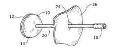
- a surgical closure patch 10comprises a disk-shaped web member 12 provided with a layer of adhesive material 14 .
- the layer of adhesive material 14is deposited on the web member 12 at the time of manufacture.
- a surgical closure device 16comprises a delivery tube 18 and an ejection rod 20 inserted in the delivery tube. Patch 10 is provided in a folded or collapsed configuration 22 inside a distal end of delivery tube 18 .
- Closure device 16is used exemplarily during a laparoscopic procedure to close a perforation in the abdominal wall or in an internal organ of a patient.
- the method of the present inventionis particularly useful for closing perforations formed in internal organs during trans-organ surgery as described in U.S. Pat. Nos. 5,297,536 and 5,458,131.
- the distal end portion of surgical closure device 10 particularly including delivery tube 18is inserted through a natural body opening such as the mouth, the vaginal orifice, the anus, or the urethral opening and utilized as discussed below with reference to FIGS. 3A-3E or 6 A- 6 F to close a perforation formed in the wall of the stomach, the vagina, the colon, or the urinary bladder, respectively.
- delivery tube 18 and rod 20are flexible members that enable the insertion of device 16 along a path having one or more curves.
- a perforation, opening, wound, or incision 24is formed in a wall 26 of an internal hollow body organ.
- perforation or incision 24is closed by inserting a distal end portion (not separately enumerated) of the device 16 , particularly including tube 18 , into the hollow body organ through a natural orifice, as shown in FIG. 3A .
- the distal end portion of device 16is then inserted through perforation 24 , as shown in FIG. 3B .
- ejection or push rod 20is shifted in the distal direction along tube 18 to eject web member 12 from the distal end of the tube.
- the ejected web member 12expands from the collapsed configuration 22 to the expanded configuration, as shown in FIG. 3C .
- the expanded surgical patch 10is placed in contact with the wall 26 of the organ over the perforation 24 by pulling rod 20 in the proximal direction as indicated by an arrow 28 in FIG. 3D .
- rod 20is detached from web member 12 , thereby leaving patch 10 in place over the perforation 24 .
- This detachmentmay be implemented, for instance, by twisting rod 20 about its longitudinal axis.
- rod 20may be provided with a score line (not shown) at a distal end, in the vicinity of web member 12 , to facilitate the separation of rod 20 from web member 12 .
- a score linenot shown
- rod 20 and delivery tube 18are removed from the patient via the natural body opening through which they were inserted.
- Web member 12 and rod 20are made of a biocompatible and optionally bioabsorbable material.
- the adhesive material of layer 14is also biocompatible and optionally bioabsorbable.
- adhesive layer 14may be rendered temporarily inactive through the application of a protective lubricating film of a volatile substance that dissipates into the insufflated abdominal cavity (see U.S. Pat. Nos. 5,297,536 and 5,458,131), thereby rendering adhesive layer 14 active.
- a surgical patch 30has a disk-shaped web member 32 made of a flexible biocompatible material and a layer of adhesive material 34 that is applied to web member 32 in a dormant or inactive state.
- the adhesive materialis rendered active (e.g., tacky) by applying energy 36 to the adhesive layer 34 via an instrument or device 38 .
- the energy 36may by heat energy, infrared radiation, ultrasonic pressure wave energy, etc.
- web member 32is provided with a shape-memory network or lattice extending between a center of the web member and a periphery thereof and including a series of radiating ribs 40 and rings 42 made of a shape-memory material such as Nitinol.
- a shape-memory network or latticeextending between a center of the web member and a periphery thereof and including a series of radiating ribs 40 and rings 42 made of a shape-memory material such as Nitinol.
- a perforation, opening, wound, or incision 46is formed in a wall 48 of an internal hollow body organ.
- perforation or incision 46is closed by inserting a distal end portion (not separately enumerated) of delivery tube 44 into the hollow body organ through a natural orifice, as shown in FIG. 6A .
- the distal end portion of tube 44is then inserted through perforation 46 , as shown in FIG. 6B .
- an ejection or push rod 50is shifted in the distal direction along tube 44 to eject web member 32 from the distal end of the tube.
- the ejected web member 32expands from the collapsed configuration to the expanded configuration, as shown in FIG. 6C .
- the expanded surgical patch 30is placed in contact with the wall 48 of the organ over the perforation 46 by pulling rod 50 in the proximal direction as indicated by an arrow 52 in FIG. 6D .
- Delivery tube 44is generally pulled back through incision or perforation 46 prior to the pulling of the expanded patch 30 in contact with the outer (non-mucosal) surface of organ wall 48 .
- a distal end portion of instrument 38is inserted into the patient, exemplarily via the same path as delivery tube 44 , and the instrument is operated to apply activation energy 36 to adhesive layer 34 through organ wall 48 to thereby activate the adhesive material ( FIG. 6E ).
- rod 50is detached from web member 32 , thereby leaving patch 30 in place over the perforation 46 only on the outer surface of organ wall 48 , with an inner side of organ wall 48 being free of the closure device, as depicted in FIG. 6F .
- This detachmentmay be implemented as discussed above, by twisting rod 50 about its longitudinal axis.
- rod 50may be provided with a score line (not shown) at a distal end, in the vicinity of web member 32 , to facilitate the separation of rod 50 from web member 32 .
- rod 50 and delivery tube 44are removed from the patient via the natural body opening through which they were inserted.
- adhesive layer 14may be applied to a major surface of web member 12 after the unfolding or expanding thereof inside a patient (for instance, inside an abdominal cavity that is insufflated with carbon dioxide gas).
- a tube with a spray nozzle(not shown) may be inserted into the patient for coating the major surface of the web member with the layer of adhesive.
- activation energy 36may be applied to adhesive layer 34 after the expansion of web member 32 from the collapse configuration and prior to the bringing of the expanded web member into contact with organ wall 48 .
- activation energy 36is applied to adhesive layer 34 via instrument 38 by first inserting a distal end portion of that instrument through the perforation 46 in organ wall 48 .
- Activation energy 36is then applied directly to adhesive layer 34 inside the abdominal cavity of the patient.
- activation energy 36can take the form of electromagnetic radiation of any suitable frequency band.
- ultrasonic vibrational energymay be the activating energy 36 .
- activation energy 36is applied through web member 32 , for instance, from inside the abdominal cavity of the patient.
- the distal end portion of instrument 38is inserted into the patient along an alternate route different from the path of tube 44 and rod 50 .
- Instrument 38may be inserted into the patient via tube 44 .
- the functions of instrument 38may be incorporated as an integral part of tube 44 .
Landscapes
- Health & Medical Sciences (AREA)
- Surgery (AREA)
- Life Sciences & Earth Sciences (AREA)
- Biomedical Technology (AREA)
- Nuclear Medicine, Radiotherapy & Molecular Imaging (AREA)
- Engineering & Computer Science (AREA)
- Heart & Thoracic Surgery (AREA)
- Medical Informatics (AREA)
- Molecular Biology (AREA)
- Animal Behavior & Ethology (AREA)
- General Health & Medical Sciences (AREA)
- Public Health (AREA)
- Veterinary Medicine (AREA)
- Cardiology (AREA)
- Surgical Instruments (AREA)
Abstract
Description
Claims (15)
Priority Applications (2)
| Application Number | Priority Date | Filing Date | Title |
|---|---|---|---|
| US11/387,528US7753934B2 (en) | 2005-04-22 | 2006-03-23 | Medical closure method and associated device |
| PCT/US2006/014385WO2006115876A2 (en) | 2005-04-22 | 2006-04-18 | Medical closure device and associated method |
Applications Claiming Priority (2)
| Application Number | Priority Date | Filing Date | Title |
|---|---|---|---|
| US67438705P | 2005-04-22 | 2005-04-22 | |
| US11/387,528US7753934B2 (en) | 2005-04-22 | 2006-03-23 | Medical closure method and associated device |
Publications (2)
| Publication Number | Publication Date |
|---|---|
| US20060241688A1 US20060241688A1 (en) | 2006-10-26 |
| US7753934B2true US7753934B2 (en) | 2010-07-13 |
Family
ID=37188021
Family Applications (1)
| Application Number | Title | Priority Date | Filing Date |
|---|---|---|---|
| US11/387,528Active2029-05-13US7753934B2 (en) | 2005-04-22 | 2006-03-23 | Medical closure method and associated device |
Country Status (2)
| Country | Link |
|---|---|
| US (1) | US7753934B2 (en) |
| WO (1) | WO2006115876A2 (en) |
Cited By (2)
| Publication number | Priority date | Publication date | Assignee | Title |
|---|---|---|---|---|
| US20100106068A1 (en)* | 2008-10-29 | 2010-04-29 | Wilson-Cook Medical Inc. | Endoscopic sheet delivery |
| US20100147990A1 (en)* | 2008-12-11 | 2010-06-17 | Wilson-Cook Medical., Inc. | Endoscopic sheet rolling system |
Families Citing this family (43)
| Publication number | Priority date | Publication date | Assignee | Title |
|---|---|---|---|---|
| EP2133030A1 (en) | 1997-06-27 | 2009-12-16 | The Trustees of Columbia University of the City of New York | Method and apparatus for circulatory valve repair |
| FR2768324B1 (en) | 1997-09-12 | 1999-12-10 | Jacques Seguin | SURGICAL INSTRUMENT FOR PERCUTANEOUSLY FIXING TWO AREAS OF SOFT TISSUE, NORMALLY MUTUALLY REMOTE, TO ONE ANOTHER |
| US7226467B2 (en) | 1999-04-09 | 2007-06-05 | Evalve, Inc. | Fixation device delivery catheter, systems and methods of use |
| AU770243B2 (en) | 1999-04-09 | 2004-02-19 | Evalve, Inc. | Methods and apparatus for cardiac valve repair |
| US6752813B2 (en) | 1999-04-09 | 2004-06-22 | Evalve, Inc. | Methods and devices for capturing and fixing leaflets in valve repair |
| US10327743B2 (en) | 1999-04-09 | 2019-06-25 | Evalve, Inc. | Device and methods for endoscopic annuloplasty |
| US20040044350A1 (en) | 1999-04-09 | 2004-03-04 | Evalve, Inc. | Steerable access sheath and methods of use |
| US6575971B2 (en) | 2001-11-15 | 2003-06-10 | Quantum Cor, Inc. | Cardiac valve leaflet stapler device and methods thereof |
| US10631871B2 (en) | 2003-05-19 | 2020-04-28 | Evalve, Inc. | Fixation devices, systems and methods for engaging tissue |
| JP4774048B2 (en) | 2004-05-14 | 2011-09-14 | エヴァルヴ インコーポレイテッド | Locking mechanism of fixing device engaged with tissue and tissue engaging method |
| WO2006037073A2 (en) | 2004-09-27 | 2006-04-06 | Evalve, Inc. | Methods and devices for tissue grasping and assessment |
| US8052592B2 (en) | 2005-09-27 | 2011-11-08 | Evalve, Inc. | Methods and devices for tissue grasping and assessment |
| CA2597066C (en) | 2005-02-07 | 2014-04-15 | Evalve, Inc. | Methods, systems and devices for cardiac valve repair |
| WO2011034628A1 (en) | 2005-02-07 | 2011-03-24 | Evalve, Inc. | Methods, systems and devices for cardiac valve repair |
| WO2008066920A2 (en)* | 2006-11-28 | 2008-06-05 | Stryker Development Llc | Gastrotomy closure device |
| US9113851B2 (en)* | 2007-08-23 | 2015-08-25 | Cook Biotech Incorporated | Fistula plugs and apparatuses and methods for fistula plug delivery |
| EP2477555B1 (en) | 2009-09-15 | 2013-12-25 | Evalve, Inc. | Device for cardiac valve repair |
| WO2012170493A1 (en)* | 2011-06-10 | 2012-12-13 | Mount Sinai School Of Medicine | Apparatus for closing an opening, such as a trocar opening, in a patient's body |
| US8945177B2 (en) | 2011-09-13 | 2015-02-03 | Abbott Cardiovascular Systems Inc. | Gripper pusher mechanism for tissue apposition systems |
| US9572666B2 (en) | 2014-03-17 | 2017-02-21 | Evalve, Inc. | Mitral valve fixation device removal devices and methods |
| US10390943B2 (en) | 2014-03-17 | 2019-08-27 | Evalve, Inc. | Double orifice device for transcatheter mitral valve replacement |
| US10188392B2 (en) | 2014-12-19 | 2019-01-29 | Abbott Cardiovascular Systems, Inc. | Grasping for tissue repair |
| US10524912B2 (en) | 2015-04-02 | 2020-01-07 | Abbott Cardiovascular Systems, Inc. | Tissue fixation devices and methods |
| US10376673B2 (en) | 2015-06-19 | 2019-08-13 | Evalve, Inc. | Catheter guiding system and methods |
| US10238494B2 (en) | 2015-06-29 | 2019-03-26 | Evalve, Inc. | Self-aligning radiopaque ring |
| US10667815B2 (en) | 2015-07-21 | 2020-06-02 | Evalve, Inc. | Tissue grasping devices and related methods |
| US10413408B2 (en) | 2015-08-06 | 2019-09-17 | Evalve, Inc. | Delivery catheter systems, methods, and devices |
| US10238495B2 (en) | 2015-10-09 | 2019-03-26 | Evalve, Inc. | Delivery catheter handle and methods of use |
| US10736632B2 (en) | 2016-07-06 | 2020-08-11 | Evalve, Inc. | Methods and devices for valve clip excision |
| US11071564B2 (en) | 2016-10-05 | 2021-07-27 | Evalve, Inc. | Cardiac valve cutting device |
| US10363138B2 (en) | 2016-11-09 | 2019-07-30 | Evalve, Inc. | Devices for adjusting the curvature of cardiac valve structures |
| US10398553B2 (en) | 2016-11-11 | 2019-09-03 | Evalve, Inc. | Opposing disk device for grasping cardiac valve tissue |
| US10426616B2 (en) | 2016-11-17 | 2019-10-01 | Evalve, Inc. | Cardiac implant delivery system |
| US10779837B2 (en) | 2016-12-08 | 2020-09-22 | Evalve, Inc. | Adjustable arm device for grasping tissues |
| US10314586B2 (en) | 2016-12-13 | 2019-06-11 | Evalve, Inc. | Rotatable device and method for fixing tricuspid valve tissue |
| WO2018209313A1 (en) | 2017-05-12 | 2018-11-15 | Evalve, Inc. | Long arm valve repair clip |
| US12102531B2 (en) | 2018-10-22 | 2024-10-01 | Evalve, Inc. | Tissue cutting systems, devices and methods |
| JP7543391B2 (en) | 2019-07-15 | 2024-09-02 | エバルブ,インコーポレイティド | Method of Actuating Individual Proximal Elements |
| US12414811B2 (en) | 2020-05-06 | 2025-09-16 | Evalve, Inc. | Devices and methods for leaflet cutting |
| US12171485B2 (en) | 2020-05-06 | 2024-12-24 | Evalve, Inc. | Systems and methods for leaflet cutting using a hook catheter |
| US12048448B2 (en) | 2020-05-06 | 2024-07-30 | Evalve, Inc. | Leaflet grasping and cutting device |
| US12171486B2 (en) | 2020-05-06 | 2024-12-24 | Evalve, Inc. | Devices and methods for clip separation |
| US12178444B2 (en) | 2020-05-06 | 2024-12-31 | Evalve, Inc. | Clip removal systems and methods |
Citations (8)
| Publication number | Priority date | Publication date | Assignee | Title |
|---|---|---|---|---|
| US4852568A (en) | 1987-02-17 | 1989-08-01 | Kensey Nash Corporation | Method and apparatus for sealing an opening in tissue of a living being |
| US5297536A (en) | 1992-08-25 | 1994-03-29 | Wilk Peter J | Method for use in intra-abdominal surgery |
| US5458131A (en) | 1992-08-25 | 1995-10-17 | Wilk; Peter J. | Method for use in intra-abdominal surgery |
| US5810721A (en) | 1996-03-04 | 1998-09-22 | Heartport, Inc. | Soft tissue retractor and method for providing surgical access |
| US5948427A (en) | 1996-04-25 | 1999-09-07 | Point Medical Corporation | Microparticulate surgical adhesive |
| US6126675A (en)* | 1999-01-11 | 2000-10-03 | Ethicon, Inc. | Bioabsorbable device and method for sealing vascular punctures |
| US6171329B1 (en)* | 1994-12-19 | 2001-01-09 | Gore Enterprise Holdings, Inc. | Self-expanding defect closure device and method of making and using |
| US6245076B1 (en) | 1999-03-11 | 2001-06-12 | Advanced Cardiovascular Systems, Inc. | Temperature activated adhesive for releasably attaching stents to balloons |
- 2006
- 2006-03-23USUS11/387,528patent/US7753934B2/enactiveActive
- 2006-04-18WOPCT/US2006/014385patent/WO2006115876A2/enactiveApplication Filing
Patent Citations (8)
| Publication number | Priority date | Publication date | Assignee | Title |
|---|---|---|---|---|
| US4852568A (en) | 1987-02-17 | 1989-08-01 | Kensey Nash Corporation | Method and apparatus for sealing an opening in tissue of a living being |
| US5297536A (en) | 1992-08-25 | 1994-03-29 | Wilk Peter J | Method for use in intra-abdominal surgery |
| US5458131A (en) | 1992-08-25 | 1995-10-17 | Wilk; Peter J. | Method for use in intra-abdominal surgery |
| US6171329B1 (en)* | 1994-12-19 | 2001-01-09 | Gore Enterprise Holdings, Inc. | Self-expanding defect closure device and method of making and using |
| US5810721A (en) | 1996-03-04 | 1998-09-22 | Heartport, Inc. | Soft tissue retractor and method for providing surgical access |
| US5948427A (en) | 1996-04-25 | 1999-09-07 | Point Medical Corporation | Microparticulate surgical adhesive |
| US6126675A (en)* | 1999-01-11 | 2000-10-03 | Ethicon, Inc. | Bioabsorbable device and method for sealing vascular punctures |
| US6245076B1 (en) | 1999-03-11 | 2001-06-12 | Advanced Cardiovascular Systems, Inc. | Temperature activated adhesive for releasably attaching stents to balloons |
Cited By (4)
| Publication number | Priority date | Publication date | Assignee | Title |
|---|---|---|---|---|
| US20100106068A1 (en)* | 2008-10-29 | 2010-04-29 | Wilson-Cook Medical Inc. | Endoscopic sheet delivery |
| US8529434B2 (en) | 2008-10-29 | 2013-09-10 | Cook Medical Technologies Llc | Endoscopic sheet delivery |
| US20100147990A1 (en)* | 2008-12-11 | 2010-06-17 | Wilson-Cook Medical., Inc. | Endoscopic sheet rolling system |
| US8167230B2 (en) | 2008-12-11 | 2012-05-01 | Cook Medical Technologies Llc | Endoscopic sheet rolling system |
Also Published As
| Publication number | Publication date |
|---|---|
| WO2006115876A3 (en) | 2007-03-15 |
| US20060241688A1 (en) | 2006-10-26 |
| WO2006115876A2 (en) | 2006-11-02 |
Similar Documents
| Publication | Publication Date | Title |
|---|---|---|
| US7753934B2 (en) | Medical closure method and associated device | |
| US9974530B2 (en) | Tissue securing and sealing apparatus and related methods of use | |
| US8016839B2 (en) | Intra-abdominal medical procedures and device | |
| US20060241651A1 (en) | Surgical port device and associated method | |
| US20060211919A1 (en) | Intra-abdominal medical device and associated method | |
| US20060258909A1 (en) | Methods and apparatus for maintaining sterility during transluminal procedures | |
| US7785251B2 (en) | Port extraction method for trans-organ surgery | |
| JP4485110B2 (en) | Laparoscopic surgical access tool with gas seal | |
| US8211125B2 (en) | Sterile appliance delivery device for endoscopic procedures | |
| US20070203517A1 (en) | Transgastric surgical devices and procedures | |
| US20060212063A1 (en) | Surgical device and associated trans-organ surgical method | |
| US8685058B2 (en) | Surgical closure method and associated device | |
| US20060237023A1 (en) | Transgastric tubal ligation | |
| JP2005529668A (en) | Tissue removal device | |
| CA2751851C (en) | Endoscopic forceps with removable handle | |
| US20060241674A1 (en) | Medical insert device and associated method | |
| US7879050B2 (en) | Trans-vascular surgical method and associated device | |
| JP5699392B2 (en) | Area securing instrument and endoscope provided with area securing instrument |
Legal Events
| Date | Code | Title | Description |
|---|---|---|---|
| AS | Assignment | Owner name:WILK PATENT, LLC,NEW YORK Free format text:ASSIGNMENT OF ASSIGNORS INTEREST;ASSIGNOR:WILK, PETER J.;REEL/FRAME:024405/0422 Effective date:20100514 Owner name:WILK PATENT, LLC, NEW YORK Free format text:ASSIGNMENT OF ASSIGNORS INTEREST;ASSIGNOR:WILK, PETER J.;REEL/FRAME:024405/0422 Effective date:20100514 | |
| STCF | Information on status: patent grant | Free format text:PATENTED CASE | |
| FPAY | Fee payment | Year of fee payment:4 | |
| FEPP | Fee payment procedure | Free format text:7.5 YR SURCHARGE - LATE PMT W/IN 6 MO, LARGE ENTITY (ORIGINAL EVENT CODE: M1555) | |
| MAFP | Maintenance fee payment | Free format text:PAYMENT OF MAINTENANCE FEE, 8TH YEAR, LARGE ENTITY (ORIGINAL EVENT CODE: M1552) Year of fee payment:8 | |
| FEPP | Fee payment procedure | Free format text:MAINTENANCE FEE REMINDER MAILED (ORIGINAL EVENT CODE: REM.); ENTITY STATUS OF PATENT OWNER: LARGE ENTITY | |
| FEPP | Fee payment procedure | Free format text:11.5 YR SURCHARGE- LATE PMT W/IN 6 MO, LARGE ENTITY (ORIGINAL EVENT CODE: M1556); ENTITY STATUS OF PATENT OWNER: LARGE ENTITY | |
| MAFP | Maintenance fee payment | Free format text:PAYMENT OF MAINTENANCE FEE, 12TH YEAR, LARGE ENTITY (ORIGINAL EVENT CODE: M1553); ENTITY STATUS OF PATENT OWNER: LARGE ENTITY Year of fee payment:12 |