US7753423B2 - Component assembly for a motor vehicle - Google Patents
Component assembly for a motor vehicleDownload PDFInfo
- Publication number
- US7753423B2 US7753423B2US11/970,688US97068808AUS7753423B2US 7753423 B2US7753423 B2US 7753423B2US 97068808 AUS97068808 AUS 97068808AUS 7753423 B2US7753423 B2US 7753423B2
- Authority
- US
- United States
- Prior art keywords
- tab
- component
- receiver
- retaining member
- component assembly
- Prior art date
- Legal status (The legal status is an assumption and is not a legal conclusion. Google has not performed a legal analysis and makes no representation as to the accuracy of the status listed.)
- Active, expires
Links
- 238000003780insertionMethods0.000claimsdescription4
- 230000037431insertionEffects0.000claimsdescription4
- 238000002347injectionMethods0.000claimsdescription3
- 239000007924injectionSubstances0.000claimsdescription3
- 239000000463materialSubstances0.000claimsdescription3
- 239000011347resinSubstances0.000claimsdescription2
- 229920005989resinPolymers0.000claimsdescription2
- 238000004519manufacturing processMethods0.000description3
- 230000008878couplingEffects0.000description2
- 238000010168coupling processMethods0.000description2
- 238000005859coupling reactionMethods0.000description2
- 238000001746injection mouldingMethods0.000description2
- 238000009434installationMethods0.000description2
- 238000000034methodMethods0.000description2
- 230000007246mechanismEffects0.000description1
- 238000012986modificationMethods0.000description1
- 230000004048modificationEffects0.000description1
- 238000004904shorteningMethods0.000description1
- 238000009423ventilationMethods0.000description1
Images


Classifications
- B—PERFORMING OPERATIONS; TRANSPORTING
- B62—LAND VEHICLES FOR TRAVELLING OTHERWISE THAN ON RAILS
- B62D—MOTOR VEHICLES; TRAILERS
- B62D27/00—Connections between superstructure or understructure sub-units
- B—PERFORMING OPERATIONS; TRANSPORTING
- B60—VEHICLES IN GENERAL
- B60R—VEHICLES, VEHICLE FITTINGS, OR VEHICLE PARTS, NOT OTHERWISE PROVIDED FOR
- B60R13/00—Elements for body-finishing, identifying, or decorating; Arrangements or adaptations for advertising purposes
- B60R13/02—Internal Trim mouldings ; Internal Ledges; Wall liners for passenger compartments; Roof liners
- B60R13/0206—Arrangements of fasteners and clips specially adapted for attaching inner vehicle liners or mouldings
- B—PERFORMING OPERATIONS; TRANSPORTING
- B60—VEHICLES IN GENERAL
- B60R—VEHICLES, VEHICLE FITTINGS, OR VEHICLE PARTS, NOT OTHERWISE PROVIDED FOR
- B60R13/00—Elements for body-finishing, identifying, or decorating; Arrangements or adaptations for advertising purposes
- B60R13/04—External Ornamental or guard strips; Ornamental inscriptive devices thereon
- F—MECHANICAL ENGINEERING; LIGHTING; HEATING; WEAPONS; BLASTING
- F16—ENGINEERING ELEMENTS AND UNITS; GENERAL MEASURES FOR PRODUCING AND MAINTAINING EFFECTIVE FUNCTIONING OF MACHINES OR INSTALLATIONS; THERMAL INSULATION IN GENERAL
- F16B—DEVICES FOR FASTENING OR SECURING CONSTRUCTIONAL ELEMENTS OR MACHINE PARTS TOGETHER, e.g. NAILS, BOLTS, CIRCLIPS, CLAMPS, CLIPS OR WEDGES; JOINTS OR JOINTING
- F16B5/00—Joining sheets or plates, e.g. panels, to one another or to strips or bars parallel to them
- F16B5/12—Fastening strips or bars to sheets or plates, e.g. rubber strips, decorative strips for motor vehicles, by means of clips
- F16B5/121—Fastening strips or bars to sheets or plates, e.g. rubber strips, decorative strips for motor vehicles, by means of clips fastened over the edge(s) of the sheet(s) or plate(s)
Definitions
- the inventionrelates to a component assembly for a motor vehicle. More particularly, the invention relates to a fastener arrangement for attaching components of a component assembly together.
- Motor vehiclesinclude numerous plastic molded components, such as ventilation ducts, interior panels, ornamental covers and bezels, etc. A wide variety of methods and structures are known for coupling the various plastic components in the vehicle together.
- a snap featureis a known attachment structure for fixing registers, switches, or like components to panels.
- This featureinvolves a retaining shape, usually triangular, on the part to be fixed, and a tab with a slot on the panel/bezel.
- the tabis aligned with the retaining shape during installation and flexes over and around it until the retaining shape falls into the slot on the tab, thereby locking the two parts together.
- two or more of these snap featuresare used on opposing sides to fix the parts together.
- Typical assembly clearance specified by manufacturingis on the order of 7-9 mm, which is difficult to maintain in some situations. This is a large amount of wasted space between the sub-assembly and surrounding parts.
- Current snap systemsuse the general surface of the part to be fixed as a datum. The general surface, however, is difficult to adjust when the fitting between the two parts has to be changed.
- a component assemblyfor a motor vehicle.
- the component assemblyincludes a first component and a second component.
- the first componentincludes a main wall and a tab extending outwardly from the main wall.
- the tabhas an aperture extending therethrough.
- the second componenthas a support wall and a tab receiver extending outwardly from the support wall.
- the tab receiverlockingly engages the tab to interconnect the first component and the second component.
- the tab receiverhas an end wall and a pair of guide walls extending from opposite ends of the end wall. The guide walls are spaced apart to receive the tab therebetween.
- the tab receiverhas a retaining member disposed between the side wall and extending outwardly from the support wall.
- the retaining memberextends through the aperture of the tab when the tab is fully received between the side walls.
- the tab receiverhas a rib that extends longitudinally between the retaining member and a free end of the support wall for tensioning the tab as the tab is received by the tab receiver.
- a method of assembling the aforementioned component assemblyincludes the step of adding or removing material from an injection mold tool used to form the tab receiver in order to reduce or increase, respectively, the height of the rib to address a tolerance stack in relation to the assembly of the first component and the second component to each other and/or to the vehicle.
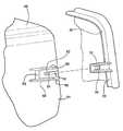
- FIG. 1is an elevational view of a component assembly according to one embodiment of the invention
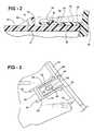
- FIG. 2is a cross sectional view of the component assembly as taken through the plane indicated at 2 - 2 in FIG. 1 ;
- FIG. 3is a partial elevational view of the component assembly enlarged to show locking engagement between a receiver on one component of the component assembly and a tab on another component of the component assembly;
- FIG. 4is a partial exploded view of the component assembly enlarged to illustrate how the tab is received by the receiver.
- the component assembly 10includes a first component 20 and a second component 40 .
- the first component 20includes a main wall 22 and a tab 30 extending outwardly from the main wall 22 .
- the tab 30has an aperture 32 extending therethrough.
- the second component 40has a support wall 51 and a tab receiver 50 extending outwardly from the support wall 51 .
- the tab receiver 50lockingly engages the tab 30 to interconnect the first component 20 and the second component 40 .
- the tab receiver 50has an end wall 62 and a pair of guide walls 64 extending from opposite ends of the end wall 62 toward the first component 20 .
- the guide walls 64are spaced apart to receive the tab 30 therebetween.
- the guide walls 64include distal ends 66 that are angled outwardly to facilitate insertion of the tab 30 into the tab receiver 50 .
- the tab receiver 50has a retaining member 52 positioned between the guide walls 64 .
- the retaining member 52extends outwardly from the support wall 51 so as to be received through the aperture 32 of the tab 30 when the tab 30 is fully received between the guide walls 64 .
- the tab receiver 50has a rib 38 that extends longitudinally between the retaining member 52 and a free end of the support wall 51 .
- the rib 38extends outwardly from the support wall 51 for contacting the tab 30 as the tab 30 is inserted into the tab receiver 50 .
- the tab receiver 50forms a boundary that protects the tab 30 and the retaining member 52 from contact with any surrounding parts during the installation of the components 20 , 40 to each other.
- angled guide ribs 58may extend between the end wall 62 and the support wall 51 to form a guide shape between the assembly 10 and any surrounding adjacent module parts during assembly.
- the boundary formed by the tab receiver 50also keeps a minimal clearance to the tab 30 disposed therein.
- the rib 38extends from the leading edge of the retaining member 52 to the free end of the support wall 51 . The tab 30 is guided by the rib 38 until it flexes over the retaining member 52 feature.
- the rib 38acts as a datum surface as it contacts the inside surface of the tab 30 to fix the two parts 20 , 40 in a direction to be datumed.
- the rib 38is typically centered inside the surrounding boundary wall defined by the tab receiver 50 and is raised a small amount above the general surface of the support wall 51 so it can be altered to adjust the fitting between the two components 20 , 40 .
- the retaining member 52includes a ramped surface 54 for displacing the tab 30 away from the support wall 51 during insertion of the tab 30 into the tab receiver 50 and facilitating location of the retaining member 52 into the aperture 32 in the tab 30 .
- the retaining member 52also includes a locating surface 34 substantially normal to the support wall 51 .
- the locating surface 34is on an opposite side of the retaining member 52 relative to the ramped surface 54 .
- the locating surface 34locates the tab 30 relative to the tab receiver 50 in at least one direction.
- the second component 40is formed of a plastic or resin material in an injection molding process.
- the height of the rib 38may be adjusted by shortening or deepening a corresponding portion of a mold in an injection molding tool to accommodate any potential tolerance condition in an assembly environment.
- first component 20 and second component 40are illustrated as a bezel and a register, respectively, in a motor vehicle.
- the first and second componentsmay also be other components or subassemblies to be coupled together in the motor vehicle, such as switches, panels and the like.
- the inventionmay be practiced other than as specifically described.
Landscapes
- Engineering & Computer Science (AREA)
- Mechanical Engineering (AREA)
- General Engineering & Computer Science (AREA)
- Chemical & Material Sciences (AREA)
- Combustion & Propulsion (AREA)
- Transportation (AREA)
- Connection Of Plates (AREA)
Abstract
Description
Claims (9)
Priority Applications (1)
| Application Number | Priority Date | Filing Date | Title |
|---|---|---|---|
| US11/970,688US7753423B2 (en) | 2008-01-08 | 2008-01-08 | Component assembly for a motor vehicle |
Applications Claiming Priority (1)
| Application Number | Priority Date | Filing Date | Title |
|---|---|---|---|
| US11/970,688US7753423B2 (en) | 2008-01-08 | 2008-01-08 | Component assembly for a motor vehicle |
Publications (2)
| Publication Number | Publication Date |
|---|---|
| US20090174222A1 US20090174222A1 (en) | 2009-07-09 |
| US7753423B2true US7753423B2 (en) | 2010-07-13 |
Family
ID=40843983
Family Applications (1)
| Application Number | Title | Priority Date | Filing Date |
|---|---|---|---|
| US11/970,688Active2028-12-08US7753423B2 (en) | 2008-01-08 | 2008-01-08 | Component assembly for a motor vehicle |
Country Status (1)
| Country | Link |
|---|---|
| US (1) | US7753423B2 (en) |
Cited By (17)
| Publication number | Priority date | Publication date | Assignee | Title |
|---|---|---|---|---|
| US20110006557A1 (en)* | 2008-09-26 | 2011-01-13 | Toyota Shatai Kabushiki Kaisha | Mounting structure for vehicle interior parts |
| US20120187722A1 (en)* | 2011-01-26 | 2012-07-26 | Nissan North America, Inc. | Connecting structure for automotive trim panels |
| US20120230761A1 (en)* | 2009-10-14 | 2012-09-13 | Nifco Inc. | Attachment structure and attachment tool |
| US20130049390A1 (en)* | 2011-08-22 | 2013-02-28 | Toyota Motor Engineering & Manufacturing North America, Inc. | Accessory Assemblies For Vehicles |
| US8590931B2 (en)* | 2011-10-28 | 2013-11-26 | Nissan North America, Inc. | Steering column cover skirt attachment |
| US8616608B1 (en) | 2012-10-05 | 2013-12-31 | Toyota Motor Engineering & Manufacturing North America, Inc. | Two-piece assembly for a wrapped panel having a hole or unique feature |
| US8678466B2 (en) | 2012-03-30 | 2014-03-25 | Toyota Motor Engineering & Manufacturing North America, Inc. | Instrument panel assembly |
| USD706203S1 (en) | 2012-03-20 | 2014-06-03 | Wald Llc | Bracket |
| USD722003S1 (en) | 2012-03-20 | 2015-02-03 | Wald Llc | Swivel bracket |
| US20150034774A1 (en)* | 2012-03-14 | 2015-02-05 | Renault S.A.S. | Device for mounting a unit, notably a radio, in a motor vehicle instrument panel compartment |
| US20150078817A1 (en)* | 2013-08-27 | 2015-03-19 | Honda Motor Co., Ltd. | Coupling structure for resin parts, and method of manufacturing same |
| US20150336518A1 (en)* | 2014-05-22 | 2015-11-26 | Ford Global Technologies, Llc | Component group for joining together vehicle parts |
| US20170225544A1 (en)* | 2016-02-04 | 2017-08-10 | Kabushiki Kaisha Toyota Jidoshokki | Register panel mounting structure |
| JP2018144575A (en)* | 2017-03-03 | 2018-09-20 | トヨタ紡織株式会社 | Vehicular functional-component mounting structure |
| US20180355897A1 (en)* | 2016-02-02 | 2018-12-13 | Bayerische Motoren Werke Aktiengesellschaft | Panel Assembly for a Motor Vehicle |
| US20190281712A1 (en)* | 2018-03-08 | 2019-09-12 | Chicony Power Technology Co., Ltd. | Fixing structure and electronic device comprising the same |
| US20190307646A1 (en)* | 2017-05-01 | 2019-10-10 | Cr Packaging Llc | Child resistant and airtight container |
Families Citing this family (1)
| Publication number | Priority date | Publication date | Assignee | Title |
|---|---|---|---|---|
| EP1826103B1 (en)* | 2006-02-28 | 2011-08-03 | Mitsubishi Jidosha Kogyo Kabushiki Kaisha | Fender panel structure |
Citations (42)
| Publication number | Priority date | Publication date | Assignee | Title |
|---|---|---|---|---|
| US1572003A (en)* | 1925-04-27 | 1926-02-09 | Fleming Rives | Stove-leg lock |
| US3409858A (en)* | 1966-08-29 | 1968-11-05 | Molex Products Co | Electrical connector having resilient arcuately bendable locking means |
| US3544951A (en)* | 1968-06-28 | 1970-12-01 | Deutsch Co Elec Comp | Coupling with deflectable arms |
| US3617077A (en)* | 1969-10-03 | 1971-11-02 | Gen Electric | Knob means for electronic device slideable control |
| US3866868A (en)* | 1974-01-16 | 1975-02-18 | Whirlpool Co | Vacuum cleaner switch mounting means |
| US4529242A (en) | 1981-10-16 | 1985-07-16 | Honda Giken Kogyo Kabushiki Kaisha | Windshield assembly for motorcycles |
| US4668004A (en)* | 1983-08-18 | 1987-05-26 | Nissan Motor Co., Ltd. | Instrument panel construction |
| US4717195A (en) | 1983-08-20 | 1988-01-05 | Nissan Motor Company, Ltd. | Instrument panel construction with stay |
| US4800980A (en) | 1985-10-05 | 1989-01-31 | Honda Giken Kogyo Kabushiki Kaisha | Body cover and trunk structure for a motor scooter |
| GB2224231A (en)* | 1988-10-25 | 1990-05-02 | Kenneth William Sharp | Brush |
| US5035443A (en)* | 1990-03-27 | 1991-07-30 | Kincheloe Chris V | Releasable snowboard binding |
| US5232185A (en)* | 1989-01-06 | 1993-08-03 | Spectra-Physics, Inc. | Method and apparatus for mounting a compact optical scanner |
| US5465049A (en) | 1992-04-20 | 1995-11-07 | Sumitomo Electric Industries, Ltd. | Integrated type planar magnetic sensor having SQUID and flux transformer formed of oxide superconductor |
| US5699601A (en)* | 1995-08-30 | 1997-12-23 | Ford Motor Company | Snap tab fastener and disassembly tool therefor |
| US5707100A (en) | 1994-10-21 | 1998-01-13 | Honda Giken Kogyo Kabushiki Kaisha | Support structure for automobile body |
| US5806916A (en) | 1995-08-30 | 1998-09-15 | Mercedes-Benz Ag | Cross member for mounting instrument panel |
| US5848855A (en)* | 1997-04-28 | 1998-12-15 | Grand Haven Stamped Products Division Of Jsj Corporation | Shifter cover arrangement |
| US5850996A (en)* | 1996-03-04 | 1998-12-22 | Two Thousand And One Technology, Inc. | Mobile telephone hanging device |
| US5898172A (en)* | 1997-02-11 | 1999-04-27 | Oki Electric Industry Co., Ltd. | Sensor mounting structure |
| US5961129A (en)* | 1997-02-07 | 1999-10-05 | Post; Peter G. | Quick-Release interlocking frame assembly for interchangeably mounting operative sports devices to a boot sole |
| US6062626A (en) | 1997-04-16 | 2000-05-16 | Mc Micro Compact Car Ag | Center console area for a motor vehicle |
| US6074150A (en)* | 1998-02-12 | 2000-06-13 | Piolax Inc. | Part mounting structure |
| US6095272A (en) | 1996-07-15 | 2000-08-01 | Yazaki Corporation | Instrument panel unit |
| US6155636A (en) | 1998-03-11 | 2000-12-05 | Meritor Automotive Gmbh | Sliding interior sunroof panel assembly for an automobile sunroof |
| US6361242B1 (en)* | 2000-02-29 | 2002-03-26 | Avaya Technology Corp. | Connector security latching mechanism |
| US6364618B1 (en)* | 2000-02-03 | 2002-04-02 | Lakewood Engineering & Mfg. Co. | Fan body assembly |
| US6376776B2 (en)* | 2000-04-20 | 2002-04-23 | Kitagawa Industries Co., Ltd. | Circuit board holder |
| US6416025B1 (en)* | 2000-07-24 | 2002-07-09 | Toyota Technical Center Usa, Inc. | Part retainer |
| US20020164206A1 (en)* | 2001-05-03 | 2002-11-07 | Kimberly Quinn | Can detente |
| US20030015364A1 (en)* | 1998-12-23 | 2003-01-23 | Mannesmann Vdo Ag | Indicating instrument |
| US6578449B1 (en) | 2002-02-18 | 2003-06-17 | Delphi Technologies, Inc. | Snap-on steering column shroud |
| US6582012B1 (en) | 2002-03-28 | 2003-06-24 | General Motors Corporation | Vehicle separator panel water management system |
| US6854783B2 (en)* | 2000-02-28 | 2005-02-15 | Mitsubishi Belting Ltd. | Multi-layer instrument panel having an accessory mounted thereon and a method of manufacturing the same |
| US20050054229A1 (en)* | 2003-09-05 | 2005-03-10 | Hideki Tsuya | Joint structure |
| US6890016B2 (en)* | 2002-06-26 | 2005-05-10 | Faurecia Interieur Industrie | Dashboard assembly and vehicle comprising the assembly |
| US7036865B2 (en) | 2004-04-08 | 2006-05-02 | Honda Motor Co., Ltd. | Automobile instrument panel structure |
| US7040686B2 (en) | 2002-06-28 | 2006-05-09 | Collins & Aikman Products Co. | Integrated center stack electronic module retention system |
| US7077452B2 (en)* | 2004-11-12 | 2006-07-18 | Toyota Technical Center Usa, Inc. | Attachment of a panel to a soft instrument panel of an automotive vehicle |
| US7234763B2 (en) | 2001-08-15 | 2007-06-26 | Dow Global Technologies Inc | Instrument panel assembly |
| US7370500B2 (en)* | 2002-06-28 | 2008-05-13 | Collins & Aikman Products Co. | Integrated center stack electronic module retention system |
| US7410206B2 (en)* | 2005-11-24 | 2008-08-12 | Moriroku Company, Ltd. | Component parts joining structure |
| US7503608B1 (en)* | 2008-01-10 | 2009-03-17 | Toyota Motor Engineering & Manufacturing North America, Inc. | Lead-in structures for front console assembly |
Family Cites Families (1)
| Publication number | Priority date | Publication date | Assignee | Title |
|---|---|---|---|---|
| US650587A (en)* | 1899-12-15 | 1900-05-29 | Louis H Mccartney | Apparatus for drying wall-paper. |
- 2008
- 2008-01-08USUS11/970,688patent/US7753423B2/enactiveActive
Patent Citations (43)
| Publication number | Priority date | Publication date | Assignee | Title |
|---|---|---|---|---|
| US1572003A (en)* | 1925-04-27 | 1926-02-09 | Fleming Rives | Stove-leg lock |
| US3409858A (en)* | 1966-08-29 | 1968-11-05 | Molex Products Co | Electrical connector having resilient arcuately bendable locking means |
| US3544951A (en)* | 1968-06-28 | 1970-12-01 | Deutsch Co Elec Comp | Coupling with deflectable arms |
| US3617077A (en)* | 1969-10-03 | 1971-11-02 | Gen Electric | Knob means for electronic device slideable control |
| US3866868A (en)* | 1974-01-16 | 1975-02-18 | Whirlpool Co | Vacuum cleaner switch mounting means |
| US4529242A (en) | 1981-10-16 | 1985-07-16 | Honda Giken Kogyo Kabushiki Kaisha | Windshield assembly for motorcycles |
| US4668004A (en)* | 1983-08-18 | 1987-05-26 | Nissan Motor Co., Ltd. | Instrument panel construction |
| US4717195A (en) | 1983-08-20 | 1988-01-05 | Nissan Motor Company, Ltd. | Instrument panel construction with stay |
| US4800980A (en) | 1985-10-05 | 1989-01-31 | Honda Giken Kogyo Kabushiki Kaisha | Body cover and trunk structure for a motor scooter |
| GB2224231A (en)* | 1988-10-25 | 1990-05-02 | Kenneth William Sharp | Brush |
| US5232185A (en)* | 1989-01-06 | 1993-08-03 | Spectra-Physics, Inc. | Method and apparatus for mounting a compact optical scanner |
| US5035443A (en)* | 1990-03-27 | 1991-07-30 | Kincheloe Chris V | Releasable snowboard binding |
| US5465049A (en) | 1992-04-20 | 1995-11-07 | Sumitomo Electric Industries, Ltd. | Integrated type planar magnetic sensor having SQUID and flux transformer formed of oxide superconductor |
| US5707100A (en) | 1994-10-21 | 1998-01-13 | Honda Giken Kogyo Kabushiki Kaisha | Support structure for automobile body |
| US5699601A (en)* | 1995-08-30 | 1997-12-23 | Ford Motor Company | Snap tab fastener and disassembly tool therefor |
| US5806916A (en) | 1995-08-30 | 1998-09-15 | Mercedes-Benz Ag | Cross member for mounting instrument panel |
| US5850996A (en)* | 1996-03-04 | 1998-12-22 | Two Thousand And One Technology, Inc. | Mobile telephone hanging device |
| US6095272A (en) | 1996-07-15 | 2000-08-01 | Yazaki Corporation | Instrument panel unit |
| US5961129A (en)* | 1997-02-07 | 1999-10-05 | Post; Peter G. | Quick-Release interlocking frame assembly for interchangeably mounting operative sports devices to a boot sole |
| US5898172A (en)* | 1997-02-11 | 1999-04-27 | Oki Electric Industry Co., Ltd. | Sensor mounting structure |
| US6062626A (en) | 1997-04-16 | 2000-05-16 | Mc Micro Compact Car Ag | Center console area for a motor vehicle |
| US5848855A (en)* | 1997-04-28 | 1998-12-15 | Grand Haven Stamped Products Division Of Jsj Corporation | Shifter cover arrangement |
| US6074150A (en)* | 1998-02-12 | 2000-06-13 | Piolax Inc. | Part mounting structure |
| US6155636A (en) | 1998-03-11 | 2000-12-05 | Meritor Automotive Gmbh | Sliding interior sunroof panel assembly for an automobile sunroof |
| US20030015364A1 (en)* | 1998-12-23 | 2003-01-23 | Mannesmann Vdo Ag | Indicating instrument |
| US6364618B1 (en)* | 2000-02-03 | 2002-04-02 | Lakewood Engineering & Mfg. Co. | Fan body assembly |
| US6854783B2 (en)* | 2000-02-28 | 2005-02-15 | Mitsubishi Belting Ltd. | Multi-layer instrument panel having an accessory mounted thereon and a method of manufacturing the same |
| US6361242B1 (en)* | 2000-02-29 | 2002-03-26 | Avaya Technology Corp. | Connector security latching mechanism |
| US6376776B2 (en)* | 2000-04-20 | 2002-04-23 | Kitagawa Industries Co., Ltd. | Circuit board holder |
| US6416025B1 (en)* | 2000-07-24 | 2002-07-09 | Toyota Technical Center Usa, Inc. | Part retainer |
| US20020164206A1 (en)* | 2001-05-03 | 2002-11-07 | Kimberly Quinn | Can detente |
| US7234763B2 (en) | 2001-08-15 | 2007-06-26 | Dow Global Technologies Inc | Instrument panel assembly |
| US7300102B2 (en) | 2001-08-15 | 2007-11-27 | Dow Global Technologies, Inc. | Instrument panel assembly |
| US6578449B1 (en) | 2002-02-18 | 2003-06-17 | Delphi Technologies, Inc. | Snap-on steering column shroud |
| US6582012B1 (en) | 2002-03-28 | 2003-06-24 | General Motors Corporation | Vehicle separator panel water management system |
| US6890016B2 (en)* | 2002-06-26 | 2005-05-10 | Faurecia Interieur Industrie | Dashboard assembly and vehicle comprising the assembly |
| US7040686B2 (en) | 2002-06-28 | 2006-05-09 | Collins & Aikman Products Co. | Integrated center stack electronic module retention system |
| US7370500B2 (en)* | 2002-06-28 | 2008-05-13 | Collins & Aikman Products Co. | Integrated center stack electronic module retention system |
| US20050054229A1 (en)* | 2003-09-05 | 2005-03-10 | Hideki Tsuya | Joint structure |
| US7036865B2 (en) | 2004-04-08 | 2006-05-02 | Honda Motor Co., Ltd. | Automobile instrument panel structure |
| US7077452B2 (en)* | 2004-11-12 | 2006-07-18 | Toyota Technical Center Usa, Inc. | Attachment of a panel to a soft instrument panel of an automotive vehicle |
| US7410206B2 (en)* | 2005-11-24 | 2008-08-12 | Moriroku Company, Ltd. | Component parts joining structure |
| US7503608B1 (en)* | 2008-01-10 | 2009-03-17 | Toyota Motor Engineering & Manufacturing North America, Inc. | Lead-in structures for front console assembly |
Cited By (31)
| Publication number | Priority date | Publication date | Assignee | Title |
|---|---|---|---|---|
| US8075034B2 (en)* | 2008-09-26 | 2011-12-13 | Toyota Shatai Kabushiki Kaisha | Mounting structure for vehicle interior parts |
| US20110006557A1 (en)* | 2008-09-26 | 2011-01-13 | Toyota Shatai Kabushiki Kaisha | Mounting structure for vehicle interior parts |
| US20120230761A1 (en)* | 2009-10-14 | 2012-09-13 | Nifco Inc. | Attachment structure and attachment tool |
| US9004804B2 (en)* | 2009-10-14 | 2015-04-14 | Nifco Inc. | Attachment structure and attachment unit |
| US20120187722A1 (en)* | 2011-01-26 | 2012-07-26 | Nissan North America, Inc. | Connecting structure for automotive trim panels |
| US8474214B2 (en)* | 2011-01-26 | 2013-07-02 | Nissan North America, Inc. | Connecting structure for automotive trim panels |
| US8678460B2 (en)* | 2011-08-22 | 2014-03-25 | Toyota Motor Engineering & Manufacturing North America, Inc. | Accessory assemblies for vehicles |
| US20130049390A1 (en)* | 2011-08-22 | 2013-02-28 | Toyota Motor Engineering & Manufacturing North America, Inc. | Accessory Assemblies For Vehicles |
| US8590931B2 (en)* | 2011-10-28 | 2013-11-26 | Nissan North America, Inc. | Steering column cover skirt attachment |
| US20150034774A1 (en)* | 2012-03-14 | 2015-02-05 | Renault S.A.S. | Device for mounting a unit, notably a radio, in a motor vehicle instrument panel compartment |
| US9738235B2 (en)* | 2012-03-14 | 2017-08-22 | Renault S.A.S. | Device for mounting a unit, notably a radio, in a motor vehicle instrument panel compartment |
| USD706203S1 (en) | 2012-03-20 | 2014-06-03 | Wald Llc | Bracket |
| USD722003S1 (en) | 2012-03-20 | 2015-02-03 | Wald Llc | Swivel bracket |
| US8678466B2 (en) | 2012-03-30 | 2014-03-25 | Toyota Motor Engineering & Manufacturing North America, Inc. | Instrument panel assembly |
| US8616608B1 (en) | 2012-10-05 | 2013-12-31 | Toyota Motor Engineering & Manufacturing North America, Inc. | Two-piece assembly for a wrapped panel having a hole or unique feature |
| US20150078817A1 (en)* | 2013-08-27 | 2015-03-19 | Honda Motor Co., Ltd. | Coupling structure for resin parts, and method of manufacturing same |
| US10286576B2 (en)* | 2013-08-27 | 2019-05-14 | Honda Motor Co., Ltd. | Coupling structure for resin parts, and method of manufacturing same |
| US10099631B2 (en)* | 2014-05-22 | 2018-10-16 | Ford Global Technologies, Llc | Component group for joining together vehicle parts |
| US20150336518A1 (en)* | 2014-05-22 | 2015-11-26 | Ford Global Technologies, Llc | Component group for joining together vehicle parts |
| US10876559B2 (en)* | 2016-02-02 | 2020-12-29 | Bayerische Motoren Werke Aktiengesellschaft | Panel assembly for a motor vehicle |
| US20180355897A1 (en)* | 2016-02-02 | 2018-12-13 | Bayerische Motoren Werke Aktiengesellschaft | Panel Assembly for a Motor Vehicle |
| US20170225544A1 (en)* | 2016-02-04 | 2017-08-10 | Kabushiki Kaisha Toyota Jidoshokki | Register panel mounting structure |
| US10967712B2 (en)* | 2016-02-04 | 2021-04-06 | Kabushiki Kaisha Toyota Jidoshokki | Register panel mounting structure |
| JP2018144575A (en)* | 2017-03-03 | 2018-09-20 | トヨタ紡織株式会社 | Vehicular functional-component mounting structure |
| US20190307646A1 (en)* | 2017-05-01 | 2019-10-10 | Cr Packaging Llc | Child resistant and airtight container |
| US10799424B2 (en)* | 2017-05-01 | 2020-10-13 | Cr Packaging Llc | Child resistant and airtight container |
| US11547634B2 (en) | 2017-05-01 | 2023-01-10 | Cr Packaging Llc | Modular system for inventory and transport efficiency of packaging |
| US11896554B2 (en) | 2017-05-01 | 2024-02-13 | Cr Packaging Llc | Child resistant and airtight container |
| US20240261190A1 (en)* | 2017-05-01 | 2024-08-08 | Cr Packaging Llc | Child resistant and airtight container |
| US12318355B2 (en)* | 2017-05-01 | 2025-06-03 | Cr Packaging Llc | Child resistant and airtight container |
| US20190281712A1 (en)* | 2018-03-08 | 2019-09-12 | Chicony Power Technology Co., Ltd. | Fixing structure and electronic device comprising the same |
Also Published As
| Publication number | Publication date |
|---|---|
| US20090174222A1 (en) | 2009-07-09 |
Similar Documents
| Publication | Publication Date | Title |
|---|---|---|
| US7753423B2 (en) | Component assembly for a motor vehicle | |
| JP5243914B2 (en) | Hole plug | |
| EP2014930B1 (en) | Article installation device | |
| US20080023223A1 (en) | Protector | |
| US10840632B2 (en) | Grommet with deformable seal | |
| US20200070750A1 (en) | Grommet | |
| WO2015008551A1 (en) | Reinforcement leaf spring for resin clip | |
| CN105452682A (en) | Snap-in fastening device, in particular a snap-in fastening device for a motor vehicle | |
| JP5346530B2 (en) | Holding frame for connector module | |
| CN114435133A (en) | System and method for securing and positioning a component relative to another component | |
| US5971330A (en) | Structure for attaching a rubber-made component part | |
| KR100803427B1 (en) | Trim mounting structure | |
| JP2009073409A (en) | Visor for automobile | |
| CN106015246A (en) | Snap fastener and metal plate | |
| CN113638954A (en) | Blind Sight Assembly Fastener System | |
| US7918494B2 (en) | Assembly type cowl top cover | |
| JPH11314552A (en) | Installation structure for vehicular grille | |
| JP5186476B2 (en) | Mounting structure for vehicle mounting parts | |
| WO2020009886A1 (en) | Fastener assembly | |
| JP2011162129A (en) | Interior part for vehicle | |
| US6683257B1 (en) | Attachment clip | |
| KR101974822B1 (en) | cooling module mounting bracket for automobile | |
| KR100820494B1 (en) | Vehicle rear door delta molding coupling structure | |
| US11611176B2 (en) | Structure for preventing connector from being detached from electronic components in vehicles | |
| KR20040005803A (en) | A rear shelf trim for a car |
Legal Events
| Date | Code | Title | Description |
|---|---|---|---|
| AS | Assignment | Owner name:TOYOTA MOTOR ENGINEERING & MANUFACTURING NORTH AME Free format text:ASSIGNMENT OF ASSIGNORS INTEREST;ASSIGNOR:ZELLNER, KERRY S., JR.;REEL/FRAME:020332/0265 Effective date:20080102 | |
| STCF | Information on status: patent grant | Free format text:PATENTED CASE | |
| AS | Assignment | Owner name:TOYOTA MOTOR CORPORATION, JAPAN Free format text:ASSIGNMENT OF ASSIGNORS INTEREST;ASSIGNOR:TOYOTA MOTOR ENGINEERING & MANUFACTURING NORTH AMERICA, INC.;REEL/FRAME:025026/0971 Effective date:20100920 | |
| FEPP | Fee payment procedure | Free format text:PAYOR NUMBER ASSIGNED (ORIGINAL EVENT CODE: ASPN); ENTITY STATUS OF PATENT OWNER: LARGE ENTITY | |
| FPAY | Fee payment | Year of fee payment:4 | |
| MAFP | Maintenance fee payment | Free format text:PAYMENT OF MAINTENANCE FEE, 8TH YEAR, LARGE ENTITY (ORIGINAL EVENT CODE: M1552) Year of fee payment:8 | |
| MAFP | Maintenance fee payment | Free format text:PAYMENT OF MAINTENANCE FEE, 12TH YEAR, LARGE ENTITY (ORIGINAL EVENT CODE: M1553); ENTITY STATUS OF PATENT OWNER: LARGE ENTITY Year of fee payment:12 |