US7752927B2 - Cable-type load sensor - Google Patents
Cable-type load sensorDownload PDFInfo
- Publication number
- US7752927B2 US7752927B2US12/357,030US35703009AUS7752927B2US 7752927 B2US7752927 B2US 7752927B2US 35703009 AUS35703009 AUS 35703009AUS 7752927 B2US7752927 B2US 7752927B2
- Authority
- US
- United States
- Prior art keywords
- cable
- conductors
- load sensor
- type load
- system alloy
- Prior art date
- Legal status (The legal status is an assumption and is not a legal conclusion. Google has not performed a legal analysis and makes no representation as to the accuracy of the status listed.)
- Expired - Fee Related
Links
Images

Classifications
- G—PHYSICS
- G01—MEASURING; TESTING
- G01L—MEASURING FORCE, STRESS, TORQUE, WORK, MECHANICAL POWER, MECHANICAL EFFICIENCY, OR FLUID PRESSURE
- G01L1/00—Measuring force or stress, in general
- G01L1/20—Measuring force or stress, in general by measuring variations in ohmic resistance of solid materials or of electrically-conductive fluids; by making use of electrokinetic cells, i.e. liquid-containing cells wherein an electrical potential is produced or varied upon the application of stress
- G01L1/205—Measuring force or stress, in general by measuring variations in ohmic resistance of solid materials or of electrically-conductive fluids; by making use of electrokinetic cells, i.e. liquid-containing cells wherein an electrical potential is produced or varied upon the application of stress using distributed sensing elements
Definitions
- the present inventionrelates to a cable-type load sensor.
- a typical electrical sensorIn conventional load sensors, a typical electrical sensor generally uses a method of detecting the load by using a pressure sensor, an accelerator sensor or a strain gage, or a method of detecting the load by the use of the modulated intensity of light inside an optical fiber caused by flexural loss and compression loss of the optical fiber.
- the distortion gaugewhich detects load by converting changes in sectional area and length of a resistor caused by applying the load to the resistor into change in electric resistance can accurately detect an amount of the load, it is used in various uses such as load cells.
- JP 06-84602 A and JP 08-313371 AAs a typical example, a method of detecting an amount of the distortion of a rigid body in which a thin film is put on the rigid body is described in JP 06-84602 A and JP 08-313371 A.
- JP 3354506 Ba sensor which detects contact at an arbitrary position along a cable is proposed in JP 3354506 B.
- An object of the present inventionis to provide a cable-type load sensor having an advantage in layout and being capable of sensing the load with a high degree of precision.
- a cable-type load sensorcomprises two conductors arranged in parallel, and an elastic cladding layer with which surroundings of two conductors are covered. And, each of the two conductors comprises at least one of a nickel chromium system alloy, an iron Ni system alloy, a copper nickel system alloy, and a nickel titanium system alloy.
- the change in an elasticity modulus characteristic of the cladding layeris 1 ⁇ 10 6 to 1.5 ⁇ 10 6 Pa in a temperature range of ⁇ 30° C. to 70° C.
- the cladding layercomprises at least one of silicone rubber and ethylene-propylene rubber.
- a low-cost and high-precision cable-type load sensoris obtained, which excels in layout and results in decreased mechanical deterioration.
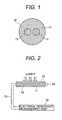
- FIG. 1is a sectional view showing a cable-type load sensor according to the present invention.
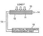
- FIG. 2is a diagrammatic illustration of a load measurement system, in which the cable-type load sensor shown in FIG. 1 is connected to an electric resistance measurement part.
- FIG. 3is a graph illustrating an output characteristic of the cable-type load sensor.
- FIG. 1is a sectional view of cable-type load sensor 10 according to the present invention
- FIG. 2is a diagrammatic illustration of a measurement system, which detects load by using cable-type load sensor 10 .
- cable-type load sensor 10is composed by arranging two conductors 11 in parallel, each of which comprises a wire rod made of electric resistance material, and by covering two conductors 11 with cladding layer 12 , which includes insulating rubber such as silicone rubber, ethylene-propylene rubber and so on.
- the load measurement system which detects the load by using this cable-type load sensor 10is composed as shown in FIG. 2 .
- One ends of conductors 11 and 11are connected electrically by using metal wire 14 , and the other ends are connected to electric resistance measurement part 15 through lead line 13 .
- Metal wire 14can be also composed by turning conductor 11 .
- electric resistance measurement part 15is composed by using a bridge circuit. Therefore, an output of electric resistance measurement part 15 is taken out as an electric power signal.
- the loadcan be detected by detecting this change in electric resistance measurement part 15 .
- the present inventionapplies the above relationship to a sensor.
- the loadcan be detected as the change in the electrical resistance R of the conductor induced by the changes in the length L and the cross-section A of the conductor, both caused by the applied load.
- the length L of the conductorbecomes longer and its cross-section A becomes smaller due to the load applied in the direction of its side face. This means that the electrical resistance R becomes larger when the load is applied in the direction of the side face.
- strain gaugesamplify the slight change in the electrical resistance of the metallic resistor by using a bridge circuit.
- strain gaugesare very high-precision device, as they have a very small sensor part, the resultant sensor apparatus become large and complex in case of detecting at arbitrary positions along the cable because it is required to layout strain gauges at those positions individually.
- the inventorsachieved a high-precision sensor which can detect the load at any position along the cable by using the material with high electric resistance as conductor 11 .
- cladding layer 12which comprises insulating rubber can detect the electric resistance of conductor 11 according to the load fluctuation with a high degree of accuracy, and it is also used to prevent the resistance change by contact with an outside conductor. Further, cladding layer 12 is desirable to have the function for generating the restoring force to return to the original shape when the load to cable-type load sensor 10 was removed. Therefore, it is preferred to use rubber material which can restore after distortion.
- cable-type load sensor 10may be used in a wide range of operating temperature
- silicone rubber or ethylene-propylene rubberwhich has smaller change in volume elasticity modulus (hardness) under operation from low temperature to high temperature as the insulating rubber.
- the change in an elasticity modulus characteristic of the cladding layeris desirable to be 1 ⁇ 10 6 to 1.5 ⁇ 10 6 Pa in a temperature range of ⁇ 30° C. to 70° C.
- the material with comparatively high electric resistance that the electric resistance change is large in relation to the stressis preferable as conductor 11 .
- a nickel chromium system alloy, an iron nickel system alloy, a copper nickel system alloy or the nickel titanium system alloyis especially suitable as the material.
- Cable-type load sensor 10was composed as follows. Two conductors 11 , which comprises the metal wire of iron chromium alloy FCHW-1 (electric resistance 11 ⁇ /m and made by Tokyo Resistance Wire Corp.) of 0.35 mm ⁇ in outside diameter were arranged in parallel with the spacing of 1 mm. Next, insulating cladding layer 12 which comprises silicone rubber of A55 in hardness of rubber was covered so that the outside diameter may become 4 mm ⁇ . It only has to be length which can be laid down to the part where the load is measured, and its length is properly set according to the part laid down though the length of cable-type load sensor 10 is not especially provided.
- FCHW-1electric resistance 11 ⁇ /m and made by Tokyo Resistance Wire Corp.
- FIG. 3shows the relationship between load and output signal strength.
- the length of cable-type load sensor 10was assumed to be 1 m.
- the load of 0 kg to 25 kgwas applied to part (the side of electric resistance measurement part 15 or the side connected electrically with metal wire 14 ) of 100 mm long of cable-type load sensor 10 of 1 m long.
Landscapes
- Physics & Mathematics (AREA)
- General Physics & Mathematics (AREA)
- Force Measurement Appropriate To Specific Purposes (AREA)
Abstract
Description
R=ρ L/A (1)
Claims (4)
Applications Claiming Priority (2)
| Application Number | Priority Date | Filing Date | Title |
|---|---|---|---|
| JP2008-011407 | 2008-01-22 | ||
| JP2008011407AJP2009174899A (en) | 2008-01-22 | 2008-01-22 | Cable type load sensor |
Publications (2)
| Publication Number | Publication Date |
|---|---|
| US20090183579A1 US20090183579A1 (en) | 2009-07-23 |
| US7752927B2true US7752927B2 (en) | 2010-07-13 |
Family
ID=40875379
Family Applications (1)
| Application Number | Title | Priority Date | Filing Date |
|---|---|---|---|
| US12/357,030Expired - Fee RelatedUS7752927B2 (en) | 2008-01-22 | 2009-01-21 | Cable-type load sensor |
Country Status (2)
| Country | Link |
|---|---|
| US (1) | US7752927B2 (en) |
| JP (1) | JP2009174899A (en) |
Families Citing this family (4)
| Publication number | Priority date | Publication date | Assignee | Title |
|---|---|---|---|---|
| JP5233292B2 (en)* | 2008-01-23 | 2013-07-10 | 日立電線株式会社 | Cable type load sensor |
| US9339116B2 (en)* | 2010-11-04 | 2016-05-17 | Applied Invention, Llc | Systems, structures and processes with embedded resistance device |
| US9016665B2 (en) | 2012-09-12 | 2015-04-28 | Goodrich Corporation | Hoist health and usage monitoring system and components thereof |
| DE102018217743A1 (en)* | 2018-10-17 | 2020-04-23 | Robert Bosch Gmbh | Cable set for a charging station, charging station |
Citations (16)
| Publication number | Priority date | Publication date | Assignee | Title |
|---|---|---|---|---|
| US3981181A (en)* | 1974-07-13 | 1976-09-21 | Sadamasa Ochiai | Method for detecting liquid leak and a cable therefor |
| US4883338A (en)* | 1987-10-15 | 1989-11-28 | Hitachi Cable, Ltd. & Hitachi, Ltd. | Synthetic resin optical fiber |
| JPH0684602A (en) | 1992-08-28 | 1994-03-25 | Tokin Corp | Thin film resistor material |
| JPH08313371A (en) | 1995-05-23 | 1996-11-29 | Tokin Corp | Force detecting device |
| US6078014A (en)* | 1995-12-04 | 2000-06-20 | Hitachi Cable, Ltd. | Cord switch and pressure sensor |
| US6107580A (en)* | 1998-02-09 | 2000-08-22 | Shinmei Rubber Industries Co., Ltd. | Omnidirectional response cable switch |
| US6122431A (en)* | 1997-09-19 | 2000-09-19 | Hitachi Cable, Ltd. | Optical transmission member |
| US20020020223A1 (en)* | 2000-08-01 | 2002-02-21 | Autonetworks Technologies, Ltd. | Load sensor, load sensor unit and insertion detection device |
| US20020079905A1 (en)* | 2000-11-16 | 2002-06-27 | Brown Richard Hunter | Cable sensor |
| JP3354506B2 (en) | 1997-12-17 | 2002-12-09 | アスモ株式会社 | Pressure sensor and method of manufacturing pressure sensor |
| US20050268734A1 (en)* | 2002-03-06 | 2005-12-08 | Watkins Jr Kenneth S | Electrical condition monitoring method for polymers |
| US7256347B2 (en)* | 2005-12-14 | 2007-08-14 | Sony Ericsson Mobile Communications Ab | Cord control and accessories having cord control for use with portable electronic devices |
| US20080011093A1 (en)* | 2001-07-09 | 2008-01-17 | Nartron Corporation | Anti-entrapment system |
| US7534957B2 (en)* | 2005-10-31 | 2009-05-19 | Hitachi Cable, Ltd. | Cord switch and detecting apparatus using the same |
| US20090133994A1 (en)* | 2007-11-22 | 2009-05-28 | Hitachi Cable, Ltd. | Cord switch |
| US20090183578A1 (en)* | 2008-01-23 | 2009-07-23 | Tomiya Abe | Cable-type load sensor |
- 2008
- 2008-01-22JPJP2008011407Apatent/JP2009174899A/enactivePending
- 2009
- 2009-01-21USUS12/357,030patent/US7752927B2/ennot_activeExpired - Fee Related
Patent Citations (18)
| Publication number | Priority date | Publication date | Assignee | Title |
|---|---|---|---|---|
| US3981181A (en)* | 1974-07-13 | 1976-09-21 | Sadamasa Ochiai | Method for detecting liquid leak and a cable therefor |
| US4883338A (en)* | 1987-10-15 | 1989-11-28 | Hitachi Cable, Ltd. & Hitachi, Ltd. | Synthetic resin optical fiber |
| JPH0684602A (en) | 1992-08-28 | 1994-03-25 | Tokin Corp | Thin film resistor material |
| JPH08313371A (en) | 1995-05-23 | 1996-11-29 | Tokin Corp | Force detecting device |
| US6078014A (en)* | 1995-12-04 | 2000-06-20 | Hitachi Cable, Ltd. | Cord switch and pressure sensor |
| US6316846B1 (en)* | 1995-12-04 | 2001-11-13 | Hitachi Cable, Ltd. | Cord switch and pressure sensor |
| US6122431A (en)* | 1997-09-19 | 2000-09-19 | Hitachi Cable, Ltd. | Optical transmission member |
| JP3354506B2 (en) | 1997-12-17 | 2002-12-09 | アスモ株式会社 | Pressure sensor and method of manufacturing pressure sensor |
| US6107580A (en)* | 1998-02-09 | 2000-08-22 | Shinmei Rubber Industries Co., Ltd. | Omnidirectional response cable switch |
| US20020020223A1 (en)* | 2000-08-01 | 2002-02-21 | Autonetworks Technologies, Ltd. | Load sensor, load sensor unit and insertion detection device |
| US20020079905A1 (en)* | 2000-11-16 | 2002-06-27 | Brown Richard Hunter | Cable sensor |
| US20080011093A1 (en)* | 2001-07-09 | 2008-01-17 | Nartron Corporation | Anti-entrapment system |
| US7513166B2 (en)* | 2001-07-09 | 2009-04-07 | Nartron Corporation | Anti-entrapment system |
| US20050268734A1 (en)* | 2002-03-06 | 2005-12-08 | Watkins Jr Kenneth S | Electrical condition monitoring method for polymers |
| US7534957B2 (en)* | 2005-10-31 | 2009-05-19 | Hitachi Cable, Ltd. | Cord switch and detecting apparatus using the same |
| US7256347B2 (en)* | 2005-12-14 | 2007-08-14 | Sony Ericsson Mobile Communications Ab | Cord control and accessories having cord control for use with portable electronic devices |
| US20090133994A1 (en)* | 2007-11-22 | 2009-05-28 | Hitachi Cable, Ltd. | Cord switch |
| US20090183578A1 (en)* | 2008-01-23 | 2009-07-23 | Tomiya Abe | Cable-type load sensor |
Also Published As
| Publication number | Publication date |
|---|---|
| JP2009174899A (en) | 2009-08-06 |
| US20090183579A1 (en) | 2009-07-23 |
Similar Documents
| Publication | Publication Date | Title |
|---|---|---|
| KR102482611B1 (en) | Split bridge circuit force sensor | |
| US7093499B2 (en) | Force sensor, strain sensor and methods for measuring same | |
| US20070240519A1 (en) | Mechanical quantity measuring apparatus | |
| US20100141291A1 (en) | Device including a contact detector | |
| EP2597441A2 (en) | Load cell and applications thereof | |
| CN104685314B (en) | Strain transmitter | |
| US7752927B2 (en) | Cable-type load sensor | |
| US10921176B2 (en) | WIM sensor and method for producing the WIM sensor | |
| KR101179169B1 (en) | Temperature compensated load cell comprising strain gauges | |
| JPS62220822A (en) | Piezoresistance type force measuring element | |
| EP3025129B1 (en) | Flex circuit interface for strain gauges | |
| CN205384108U (en) | Measure axial tension's resistance strain force sensor | |
| EP1571434B1 (en) | Strain detector and pressure sensor | |
| JP6566188B2 (en) | Current sensor | |
| US7779706B2 (en) | Cable-type load sensor | |
| CN104279947B (en) | Plate with the strain measurement piece for measuring deformation information | |
| Chadda et al. | 3D-printed strain gauges based on conductive filament for experimental stress analysis | |
| JP2010531982A (en) | Recording unit for detecting the input signal caused by mechanical action and method for detecting the measurement and processing the signal | |
| JP2014085259A (en) | Strain gauge, strain measuring device and strain gauge type converter | |
| JP4289226B2 (en) | Load cell and physical property evaluation test equipment | |
| KR101383041B1 (en) | Board type strain gauge sensor and board body thereof | |
| CN1031420A (en) | A kind of method of nondestructive inspection of residual stress | |
| CN222762286U (en) | Flexible magnetic sensor device capable of correcting posture | |
| JP3403840B2 (en) | Maximum deformation detection sensor | |
| JPH03210404A (en) | Shape sensor |
Legal Events
| Date | Code | Title | Description |
|---|---|---|---|
| AS | Assignment | Owner name:HITACHI CABLE, LTD., JAPAN Free format text:ASSIGNMENT OF ASSIGNORS INTEREST;ASSIGNOR:ABE, TOMIYA;REEL/FRAME:022209/0160 Effective date:20081223 | |
| FEPP | Fee payment procedure | Free format text:PAYOR NUMBER ASSIGNED (ORIGINAL EVENT CODE: ASPN); ENTITY STATUS OF PATENT OWNER: LARGE ENTITY | |
| STCF | Information on status: patent grant | Free format text:PATENTED CASE | |
| FPAY | Fee payment | Year of fee payment:4 | |
| MAFP | Maintenance fee payment | Free format text:PAYMENT OF MAINTENANCE FEE, 8TH YEAR, LARGE ENTITY (ORIGINAL EVENT CODE: M1552) Year of fee payment:8 | |
| FEPP | Fee payment procedure | Free format text:MAINTENANCE FEE REMINDER MAILED (ORIGINAL EVENT CODE: REM.); ENTITY STATUS OF PATENT OWNER: LARGE ENTITY | |
| LAPS | Lapse for failure to pay maintenance fees | Free format text:PATENT EXPIRED FOR FAILURE TO PAY MAINTENANCE FEES (ORIGINAL EVENT CODE: EXP.); ENTITY STATUS OF PATENT OWNER: LARGE ENTITY | |
| STCH | Information on status: patent discontinuation | Free format text:PATENT EXPIRED DUE TO NONPAYMENT OF MAINTENANCE FEES UNDER 37 CFR 1.362 | |
| FP | Lapsed due to failure to pay maintenance fee | Effective date:20220713 |