US7752920B2 - Modular force sensor - Google Patents
Modular force sensorDownload PDFInfo
- Publication number
- US7752920B2 US7752920B2US11/553,303US55330306AUS7752920B2US 7752920 B2US7752920 B2US 7752920B2US 55330306 AUS55330306 AUS 55330306AUS 7752920 B2US7752920 B2US 7752920B2
- Authority
- US
- United States
- Prior art keywords
- tube portion
- strain gauges
- tube
- surgical instrument
- group
- Prior art date
- Legal status (The legal status is an assumption and is not a legal conclusion. Google has not performed a legal analysis and makes no representation as to the accuracy of the status listed.)
- Active, expires
Links
Images


Classifications
- A—HUMAN NECESSITIES
- A61—MEDICAL OR VETERINARY SCIENCE; HYGIENE
- A61B—DIAGNOSIS; SURGERY; IDENTIFICATION
- A61B34/00—Computer-aided surgery; Manipulators or robots specially adapted for use in surgery
- A61B34/30—Surgical robots
- A—HUMAN NECESSITIES
- A61—MEDICAL OR VETERINARY SCIENCE; HYGIENE
- A61B—DIAGNOSIS; SURGERY; IDENTIFICATION
- A61B34/00—Computer-aided surgery; Manipulators or robots specially adapted for use in surgery
- A61B34/30—Surgical robots
- A61B34/37—Leader-follower robots
- A—HUMAN NECESSITIES
- A61—MEDICAL OR VETERINARY SCIENCE; HYGIENE
- A61B—DIAGNOSIS; SURGERY; IDENTIFICATION
- A61B34/00—Computer-aided surgery; Manipulators or robots specially adapted for use in surgery
- A61B34/70—Manipulators specially adapted for use in surgery
- A—HUMAN NECESSITIES
- A61—MEDICAL OR VETERINARY SCIENCE; HYGIENE
- A61B—DIAGNOSIS; SURGERY; IDENTIFICATION
- A61B34/00—Computer-aided surgery; Manipulators or robots specially adapted for use in surgery
- A61B34/70—Manipulators specially adapted for use in surgery
- A61B34/71—Manipulators operated by drive cable mechanisms
- A—HUMAN NECESSITIES
- A61—MEDICAL OR VETERINARY SCIENCE; HYGIENE
- A61B—DIAGNOSIS; SURGERY; IDENTIFICATION
- A61B34/00—Computer-aided surgery; Manipulators or robots specially adapted for use in surgery
- A61B34/70—Manipulators specially adapted for use in surgery
- A61B34/76—Manipulators having means for providing feel, e.g. force or tactile feedback
- A—HUMAN NECESSITIES
- A61—MEDICAL OR VETERINARY SCIENCE; HYGIENE
- A61B—DIAGNOSIS; SURGERY; IDENTIFICATION
- A61B34/00—Computer-aided surgery; Manipulators or robots specially adapted for use in surgery
- A61B34/20—Surgical navigation systems; Devices for tracking or guiding surgical instruments, e.g. for frameless stereotaxis
- A61B2034/2046—Tracking techniques
- A61B2034/2061—Tracking techniques using shape-sensors, e.g. fiber shape sensors with Bragg gratings
- A—HUMAN NECESSITIES
- A61—MEDICAL OR VETERINARY SCIENCE; HYGIENE
- A61B—DIAGNOSIS; SURGERY; IDENTIFICATION
- A61B34/00—Computer-aided surgery; Manipulators or robots specially adapted for use in surgery
- A61B34/30—Surgical robots
- A61B2034/305—Details of wrist mechanisms at distal ends of robotic arms
- A—HUMAN NECESSITIES
- A61—MEDICAL OR VETERINARY SCIENCE; HYGIENE
- A61B—DIAGNOSIS; SURGERY; IDENTIFICATION
- A61B90/00—Instruments, implements or accessories specially adapted for surgery or diagnosis and not covered by any of the groups A61B1/00 - A61B50/00, e.g. for luxation treatment or for protecting wound edges
- A61B90/06—Measuring instruments not otherwise provided for
- A61B2090/064—Measuring instruments not otherwise provided for for measuring force, pressure or mechanical tension
- A61B2090/065—Measuring instruments not otherwise provided for for measuring force, pressure or mechanical tension for measuring contact or contact pressure
- Y—GENERAL TAGGING OF NEW TECHNOLOGICAL DEVELOPMENTS; GENERAL TAGGING OF CROSS-SECTIONAL TECHNOLOGIES SPANNING OVER SEVERAL SECTIONS OF THE IPC; TECHNICAL SUBJECTS COVERED BY FORMER USPC CROSS-REFERENCE ART COLLECTIONS [XRACs] AND DIGESTS
- Y10—TECHNICAL SUBJECTS COVERED BY FORMER USPC
- Y10T—TECHNICAL SUBJECTS COVERED BY FORMER US CLASSIFICATION
- Y10T74/00—Machine element or mechanism
- Y10T74/20—Control lever and linkage systems
- Y10T74/20207—Multiple controlling elements for single controlled element
- Y10T74/20305—Robotic arm
- Y10T74/20329—Joint between elements
- Y10T74/20335—Wrist
Definitions
- the present inventionrelates generally to surgical robot systems and, more particularly, to an improved system, apparatus, and method for sensing forces applied to a surgical instrument.
- the surgeontypically operates a master controller to control the motion of surgical instruments at the surgical site from a location that may be remote from the patient (e.g., across the operating room, in a different room or a completely different building from the patient).
- the master controllerusually includes one or more hand input devices, such as handheld wrist gimbals, joysticks, exoskeletal gloves, handpieces or the like, which are operatively coupled to the surgical instruments through a controller with servo motors for articulating the instruments' position and orientation at the surgical site.
- the servo motorsare typically part of an electromechanical device or surgical manipulator arm (“the slave”) that includes a plurality of joints, linkages, etc., that are connected together to support and control the surgical instruments that have been introduced directly into an open surgical site or through trocar sleeves inserted through incisions into a body cavity, such as the patient's abdomen.
- the slaveincludes a plurality of joints, linkages, etc., that are connected together to support and control the surgical instruments that have been introduced directly into an open surgical site or through trocar sleeves inserted through incisions into a body cavity, such as the patient's abdomen.
- surgical instrumentssuch as tissue graspers, needle drivers, electrosurgical cautery probes, etc.
- a surgeonmay employ a large number of different surgical instruments/tools during a procedure.
- This new method of performing telerobotic surgery through remote manipulationhas created many new challenges.
- One such challengeis providing the surgeon with the ability to accurately “feel” the tissue that is being manipulated by the surgical instrument via the robotic manipulator.
- the surgeonmust rely on visual indications of the forces applied by the instruments or sutures. It is desirable to sense the forces and torques applied to the tip of the instrument, such as an end effector (e.g., jaws, grasper, blades, etc.) of robotic endoscopic surgical instruments, in order to feed the forces and torques back to the surgeon user through the system hand controls or by other means such as visual display or audible tone.
- an end effectore.g., jaws, grasper, blades, etc.
- One device for this purposefrom the laboratory of G. Hirzinger at DLR is described in “Review of Fixtures for Low-Invasiveness Surgery” by F.
- Another problemhas been fitting and positioning the necessary wires for mechanical actuation of end effectors in as small a space as possible as relatively small instruments are typically desirable for performing surgery.
- a modular force sensorincludes a tube portion including a plurality of strain gauges, a proximal tube portion for operably coupling to a shaft of a surgical instrument that may be operably coupled to a manipulator arm of a robotic surgical system, and a distal tube portion for proximally coupling to a wrist joint coupled to an end portion.
- Groups of axially oriented strain gaugesare positioned on or near a distal end of an instrument shaft proximal to (or inboard of) a moveable wrist of a robotic surgical instrument via a modular apparatus to sense forces and torques at the distal tip of the instrument without errors due to changes in the configuration of the tip (such as with a moveable wrist) or steady state temperature variations.
- the present inventionimproves the sensing and feedback of forces and/or torques to the surgeon and substantially eliminates the problem of passing delicate wires through the flexible wrist joint of the instrument.
- a force sensor apparatusmay be manufactured, tested, and calibrated as a separate modular component and brought together with other components in the conventional instrument assembly process.
- FIG. 1Ais a perspective view of a robotic surgical system and method in accordance with an embodiment of the present invention.
- FIG. 1Bis a perspective view of a robotic surgical arm cart system of the robotic surgical system in FIG. 1A in accordance with an embodiment of the present invention.
- FIG. 1Cis a front perspective view of a master console of the robotic surgical system in FIG. 1A in accordance with an embodiment of the present invention.
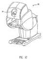
- FIG. 2is a perspective view of a surgical instrument including a modular force sensor apparatus operably coupled proximal (or inboard) to a wrist joint in accordance with an embodiment of the present invention.
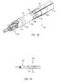
- FIG. 3Ais a perspective view of a modular force sensor apparatus in accordance with an embodiment of the present invention.
- FIG. 3Billustrates the modular force sensor of FIG. 3A operably coupled to a shaft and end portion of a surgical instrument in accordance with an embodiment of the present invention.
- FIG. 3Cillustrates the modular force sensor of FIG. 3A with a protective cover over a portion of the modular force sensor in accordance with an embodiment of the present invention.
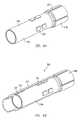
- FIG. 4Ais a perspective view of an inner tube of a modular force sensor apparatus in accordance with another embodiment of the present invention.
- FIG. 4Bis a partial cross-sectional view of an outer tube/cover over the inner tube of FIG. 4A of the modular force sensor apparatus in accordance with an embodiment of the present invention.
- FIG. 4Cshows intervening material between the inner and outer tubes of FIG. 4B of the modular force sensor apparatus and wires or fiber optic cables operably coupled to the modular force sensor apparatus in accordance with an embodiment of the present invention.
- FIG. 4Dshows a partial cross-sectional view of the modular force sensor apparatus operably coupled proximal to (or inboard of) a wrist joint of a surgical instrument in accordance with an embodiment of the present invention.
- the present inventionprovides a multi-component system, apparatus, and method for sensing forces applied to tissue while performing robotically-assisted surgical procedures on a patient, particularly including open surgical procedures, neurosurgical procedures, such as stereotaxy, and endoscopic procedures, such as laparoscopy, arthroscopy, thoracoscopy and the like.
- the apparatus and method of the present inventionare particularly useful as part of a telerobotic surgical system that allows the surgeon to manipulate the surgical instruments through a servomechanism from a remote location from the patient.
- the manipulator apparatus or slave of the present inventionwill usually be driven by a kinematically-equivalent master having six or more degrees of freedom (e.g., 3 degrees of freedom for position and 3 degrees of freedom for orientation) to form a telepresence system with force reflection.
- a kinematically-equivalent masterhaving six or more degrees of freedom (e.g., 3 degrees of freedom for position and 3 degrees of freedom for orientation) to form a telepresence system with force reflection.
- degrees of freedome.g., 3 degrees of freedom for position and 3 degrees of freedom for orientation
- robotic system 10generally includes one or more surgical manipulator assemblies 51 mounted to or near an operating table O, and a master control assembly located at a surgeon's console 90 for allowing the surgeon S to view the surgical site and to control the manipulator assemblies 51 .
- the system 10will also include one or more viewing scope assemblies and a plurality of surgical instrument assemblies 54 adapted for being removably coupled to the manipulator assemblies 51 (discussed in more detail below).
- Robotic system 10usually includes at least two manipulator assemblies 51 and preferably three manipulator assemblies 51 .
- manipulator assemblies 51will depend on the surgical procedure and the space constraints within the operating room among other factors. As discussed in detail below, one of the assemblies 51 will typically operate a viewing scope assembly (e.g., in endoscopic procedures) for viewing the surgical site, while the other manipulator assemblies 51 operate surgical instruments 54 for performing various procedures on the patient P.
- a viewing scope assemblye.g., in endoscopic procedures
- surgical instruments 54for performing various procedures on the patient P.
- the control assemblymay be located at a surgeon's console 90 which is usually located in the same room as operating table O so that the surgeon may speak to his/her assistant(s) and directly monitor the operating procedure. However, it should be understood that the surgeon S can be located in a different room or a completely different building from the patient P.
- the master control assemblygenerally includes a support, a monitor for displaying an image of the surgical site to the surgeon S, and one or more master(s) for controlling manipulator assemblies 51 .
- Master(s)may include a variety of input devices, such as hand-held wrist gimbals, joysticks, gloves, trigger-guns, hand-operated controllers, voice recognition devices or the like.
- master(s)will be provided with the same degrees of freedom as the associated surgical instrument assemblies 54 to provide the surgeon with telepresence, the perception that the surgeon is immediately adjacent to and immersed in the surgical site, and intuitiveness, the perception that the master(s) are integral with the instruments 54 so that the surgeon has a strong sense of directly and intuitively controlling instruments 54 as if they are part of his hands.
- Position, force, and tactile feedback sensorsmay also be employed on instrument assemblies 54 to transmit position, force, and tactile sensations from the surgical instrument back to the surgeon's hands as he/she operates the telerobotic system.
- the monitor 94will be suitably coupled to the viewing scope assembly such that an image of the surgical site is provided adjacent the surgeon's hands on surgeon console.
- monitor 94will display an image on a display that is oriented so that the surgeon feels that he or she is actually looking directly down onto the operating site.
- an image of the surgical instruments 54appears to be located substantially where the operator's hands are located even though the observation points (i.e., the endoscope or viewing camera) may not be from the point of view of the image.
- the real-time imageis preferably transformed into a stereo image such that the operator can manipulate the end effector and the hand control as if viewing the workspace in substantially true presence.
- a servo controlis provided for transferring the mechanical motion of masters to manipulator assemblies 51 .
- the servo controlmay be separate from, or integral with the console 90 .
- the servo controlwill usually provide force and torque feedback from the surgical instruments 54 to the hand-operated masters.
- the servo controlmay include a safety monitoring controller (not shown) to safely halt system operation or at least inhibit all robot motion in response to recognized undesirable conditions (e.g., exertion of excessive force on the patient, mismatched encoder readings, etc.).
- the servo controlpreferably has a servo bandwidth with a 3 dB cut off frequency of at least 10 hz so that the system can quickly and accurately respond to the rapid hand motions used by the surgeon and yet to filter out undesirable surgeon hand tremors.
- manipulator assemblies 51have a relatively low inertia, and the drive motors have relatively low ratio gear or pulley couplings.
- Any suitable conventional or specialized servo controlmay be used in the practice of the present invention, with those incorporating force and torque feedback being particularly preferred for telepresence operation of the system.
- FIG. 2a perspective view is shown of a surgical instrument 54 including a modular force sensor apparatus 100 operably coupled to a distal end of a rigid shaft 110 and proximal to a wrist joint 121 in accordance with an embodiment of the present invention.
- An end portion 120such as a surgical end effector, is coupled to force sensor apparatus 100 via the wrist joint 121 .
- a housing 150is operably coupled to a proximal end of the rigid shaft 110 and includes an interface 152 which mechanically and electrically couples instrument 54 to the manipulator 51 .
- FIG. 3Ashows a perspective view of modular force sensor apparatus 100 including in one embodiment a tube 102 including a number (e.g., 3, 4, 6, or 8) of strain gauges 104 (e.g., 104 a and 104 b ) mounted to a surface of tube 102 and oriented axially (parallel to the lengthwise axis z of the tube).
- FIG. 3Bshows the modular force sensor apparatus 100 of FIG.
- FIG. 3Aoperably coupled to a shaft 110 and end portion 120 of a surgical instrument in accordance with an embodiment of the present invention.
- FIG. 3Cshows a cross-section view of modular force sensor apparatus 100 including a cover or sleeve 113 over tube 102 .
- force sensor apparatus 100is a separately manufacturable module adapted for incorporation as part of the shaft 110 of laparoscopic surgical instrument 54 at a prescribed distance from the tip where there may be an articulated wrist with specialized jaws, cutting devices, or other end portion 120 .
- tube 102may be made of a sufficiently strong material and may be spool shaped, including end portions 102 b , 102 c with a depressed portion 102 a therebetween. Strain gauges 104 may be mounted on the surface of depressed portion 102 a .
- Proximal tube portion 102 coperably couples to the shaft 110 of surgical instrument 54 and distal tube portion 102 b operably couples to a wrist joint 121 .
- the diameter of the completed force sensor apparatusmatches the diameter of the instrument shaft, thus allowing the entire assembly of the instrument (including the coupled force sensor apparatus) to pass through a cannula or a seal without added friction or snagging.
- Force sensor apparatus 100includes a through passage 109 for end portion actuation cables or rods. End features 108 of end portion 102 b insure secure mounting and angular alignment to the main instrument shaft and wrist/jaw/other end portion sub-assembly of the instrument.
- Wire leads or optic fibers 116e.g., shielded twisted pairs, coax, or fiber
- the wire leads or optic fibers 116may then be embedded in an adhesive potting compound such as epoxy.
- cover 113is positioned over and encapsulates the mounted strain gauges 104 and other circuit elements on the surface of the tube 102 , thereby providing mechanical protection of the sensors.
- cover 113is a mechanically protective woven sleeve potted on depressed portion 102 a and is comprised of a woven resin impregnated fiberglass or metal braid electrical shielding.
- strain gauges 104may be spaced in a ring at intervals around the circumference of the tube 102 (e.g., 3 gauges at 120 degrees or 4 gauges at 90 degrees).
- the signals from the sensorsare combined arithmetically in various sums and differences to obtain measures of three perpendicular forces (e.g., F x , F y , and F z ) exerted upon the instrument tip and the torques about the two axes perpendicular to the shaft axis (i.e., axes x and y).
- the measurement of the forcesis made independent of the orientation and effective lever arm length of an articulated wrist mechanism at the distal end of the instrument when two sets or rings of gauges are utilized.
- Forces exerted against end portion 120are detected by the force sensing elements, which may be operably coupled to the servo control via an interrogator or a processor for notifying the surgeon of these forces (e.g., via master(s)).
- various strain gaugesmay be used, including but not limited to conventional foil type resistance gauges, semiconductor gauges, optic fiber type gauges using Bragg grating or Fabry-Perot technology, or others, such as strain sensing surface acoustic wave (SAW) devices.
- SAWstrain sensing surface acoustic wave
- FBGOptic fiber Bragg grating
- Both fiber technologiesrequire an interrogator unit that decodes the optically encoded strain information into electrical signals compatible with the computer control hardware of the robotic surgical system.
- a processormay then be used to calculate forces according to the signals from the strain gauges/sensors.
- strain gauge bridge circuitsare completed in a manner to give the best signal for bending loads due to the lateral forces (F x and F y ) exerted on the instrument tip jaws.
- active componentssuch as bare die op-amps and passive components such as secondary resistors or capacitors may be attached adjacent to the strain gauges connected by bond wires or optic fibers or thick film circuit traces in the manner of hybrid circuits to amplify, filter, and/or modulate the gauge output signals to reject noise sources.
- passive componentssuch as secondary resistors or capacitors may be attached adjacent to the strain gauges connected by bond wires or optic fibers or thick film circuit traces in the manner of hybrid circuits to amplify, filter, and/or modulate the gauge output signals to reject noise sources.
- Such componentsare not needed for fiber optic gauges.
- Surgical instrument 54 to which force sensor apparatus 100 couplesmay include a circumferentially coiled insulated flex circuit style service loop of parallel conductive traces at the proximal end of the instrument shaft 110 permitting the substantially free rotation of the instrument shaft while conducting the input gauge excitation power and output gauge signals to stationary housing 150 of the instrument 54 .
- Housing 150operably interfaces with a robotic manipulator arm 51 , in one embodiment via a sterile adaptor interface 152 .
- Applicable housings, sterile adaptor interfaces, and manipulator armsare disclosed in U.S. patent application Ser. No. 11/314,040 and U.S. Provisional Application No. 60/752,755, both filed on Dec. 20, 2005, the full disclosures of which (including all references incorporated by reference therein) are incorporated by reference herein for all purposes.
- Applicable shafts, end portions, housings, sterile adaptors, and manipulator armsare available from Intuitive Surgical Inc. of Sunnyvale, Calif.
- end portion 120has a range of motion that includes pitch and yaw motion, rotation about the z-axis, and actuation of an end effector, via cables through shaft 110 and housing 150 that transfers motion and electrical signals from the manipulator arm 51 . Movement of end portion 120 along the x, y, and z axes may be provided by the manipulator arm 51 .
- Embodiments of drive assemblies, arms, forearm assemblies, adaptors, and other applicable partsare described for example in U.S. Pat. Nos. 6,331,181, 6,491,701, and 6,770,081, the full disclosures of which (including disclosures incorporated by reference therein) are incorporated herein by reference for all purposes.
- various surgical instrumentsmay be improved in accordance with the present invention, including but not limited to tools with and without end effectors, such as jaws, scissors, graspers, needle holders, micro-dissectors, staple appliers, tackers, suction irrigation tools, clip appliers, cutting blades, irrigators, catheters, and suction orifices.
- the surgical instrumentmay comprise an electrosurgical probe for ablating, resecting, cutting or coagulating tissue.
- Such surgical instrumentsare commercially available from Intuitive Surgical, Inc. of Sunnyvale, Calif.
- the calibration datamay be programmed into an integrated circuit embedded in the instrument so that the surgical system using the individual instrument can correctly identify and apply its correction factors and offsets while the instrument is in use.
- force sensor apparatus 100 of the present inventionis adaptable to the size and shape constraints of robotic endoscopic surgical instruments and is suitable for a variety of instruments. Accordingly, end portions 102 b , 102 c may be formed into various applicable shapes and sizes. Furthermore, force sensor apparatus 100 may be manufactured, tested, and calibrated as a separate modular component and brought together with other components in the conventional instrument assembly process. Also, the sensor may be a slip on module with suitable electrical contacts that mate with contacts on the instrument shaft permitting a higher value sensor to be used with lower cost instruments of limited cycle life. In addition, the sensor structural member 102 may be comprised of an advantageous material, which may be a different material than the instrument shaft 110 whose design considerations may compromise the properties required for the sensor.
- FIGS. 4A through 4Da modular force sensor apparatus 200 is illustrated in accordance with another embodiment of the present invention.
- the descriptions of substantially similar parts or elements as those described above with respect to FIGS. 1-3are applicable in this embodiment with respect to FIGS. 4A-4D , although redundant descriptions will be omitted.
- FIG. 4Ais a perspective view of an inner tube 218 of modular force sensor apparatus 200 in accordance with an embodiment of the present invention.
- Inner tube 218includes a proximal raised end portion 218 b and a depressed portion 218 a .
- Strain gaugesas described above with respect to FIGS. 1-3 , may be mounted on the surface of depressed portion 218 a .
- Raised end portion 218 bmay include grooves 112 for routing of wire leads or optic fibers from strain gauges 204 .
- FIG. 4Bis a partial cross-sectional view of an outer tube 214 over the inner tube 218 .
- outer tube 214 of force sensor apparatus 200is a concentric tubular structural member made of sufficiently strong materials that can encapsulate the strain gauges and other electronics within an annular gap between the inner and outer tubes 218 and 214 .
- the concentric tubesare joined rigidly at the proximal end adjacent proximal portion 218 b while a narrow annular gap between the distal ends near a distal portion is filled with an elastomeric material 215 that prevents the high and varying axial forces of the wrist and jaw actuator cable or rods from being transmitted through the inner tube carrying the strain gauges.
- the partially isolated tube carrying the gaugesmay be either the outer or the inner tube.
- the non-isolated tube of the pairmay carry the entire axial cable load.
- the gaugesmay be placed on the interior tube to isolate the gauges from the environment.
- the outer tube 214carries the axial cable forces and also permits the outer tube to provide mechanical protection and potentially act as EMI shielding to the gauges 204 on the inner tube 218 .
- FIG. 4Chighlights elastomeric material 215 between the inner tube 218 and outer tube 214 of the modular force sensor apparatus 200 , and wires or fiber optic cables 216 operably coupled to gauges 204 .
- FIG. 4Dshows a partial cross-sectional view of the modular force sensor apparatus 200 operably coupled proximal to a wrist joint 221 of a surgical instrument in accordance with an embodiment of the present invention.
- Leads 216e.g., shielded twisted pairs, coax, or optic fiber
- the leads 216may then be embedded in an adhesive potting compound such as an epoxy.
- the wire routingmay be simplified by not requiring a rotating joint service loop.
- the relative shear and compressive properties of elastomersenables this design concept.
- a suitable elastomer 215 with a low shear moduluspermits the relative compression and extension of the cable load carrying tube with respect to the sensor carrying tube (which is connected rigidly at only one end of the tubes as mentioned above).
- cable loads and load changesdo not affect the sensors.
- an elastomer confined between two relatively rigid surfaceswhere the gap between the surfaces is small compared to the extent of the surfaces behaves as a nearly incompressible rigid connection in the direction normal to the confining surfaces, in this case the radial direction of the combined annular tube structure. This causes bending moments carried in the axially loaded tube to be transmitted to and shared by the sensor tube.
- the sensor tubecan advantageously detect the bending moments due to lateral loads on the instrument wrist and jaws without significant interference or “noise” from the higher varying axial cable loads carried by the other tube.
- the decoupling of the load carrying members in an endoscopic surgical instrument force sensorenables the separation of undesired jaw actuator tendon forces from desired lateral jaw load induced bending moments on the force sensor.
- the desired effect of axially de-constraining the sensor carrying tube from the cable load carrying tube at one endmay be obtained by inserting an annular ring of a more rigid low friction material in the annular gap between the unconnected ends of the tubes machined for a very close fit, thereby permitting the relative axial motion but transmitting the lateral motion associated with bending moments due to the lateral tip forces.
- Another alternativeis to make the tubes with a very close fit and apply a low friction coating to one or both surfaces at the distal end.
- these alternativesmay create a small deadband in sensor response depending on how close a fit may be reliably obtained.
- the expansion thermal coefficients of the inner and outer tubesmust also be matched or the required close fit may bind when heated or cooled.
Landscapes
- Health & Medical Sciences (AREA)
- Engineering & Computer Science (AREA)
- Life Sciences & Earth Sciences (AREA)
- Surgery (AREA)
- Robotics (AREA)
- Medical Informatics (AREA)
- Biomedical Technology (AREA)
- Heart & Thoracic Surgery (AREA)
- Nuclear Medicine, Radiotherapy & Molecular Imaging (AREA)
- Molecular Biology (AREA)
- Animal Behavior & Ethology (AREA)
- General Health & Medical Sciences (AREA)
- Public Health (AREA)
- Veterinary Medicine (AREA)
- Manipulator (AREA)
- Surgical Instruments (AREA)
Abstract
Description
Claims (29)
Priority Applications (15)
| Application Number | Priority Date | Filing Date | Title |
|---|---|---|---|
| US11/553,303US7752920B2 (en) | 2005-12-30 | 2006-10-26 | Modular force sensor |
| KR1020087015415AKR101296220B1 (en) | 2005-12-30 | 2006-12-13 | Modular force sensor |
| JP2008548798AJP5152993B2 (en) | 2005-12-30 | 2006-12-13 | Modular force sensor |
| EP06850942AEP1965717B1 (en) | 2005-12-30 | 2006-12-13 | Surgical instrument with modular force sensor |
| EP11150432.0AEP2289455B1 (en) | 2005-12-30 | 2006-12-13 | Modular force sensor |
| PCT/US2006/062000WO2007120329A2 (en) | 2005-12-30 | 2006-12-13 | Modular force sensor |
| CN2006800463204ACN101325920B (en) | 2005-12-30 | 2006-12-13 | Modular Force Sensor |
| US12/793,014US8281670B2 (en) | 2005-12-30 | 2010-06-03 | Modular force sensor |
| JP2012119920AJP5431527B2 (en) | 2005-12-30 | 2012-05-25 | Modular force sensor |
| US13/892,223US9055962B2 (en) | 2005-03-30 | 2013-05-10 | Optic fiber connection for a force sensing instrument |
| US13/897,700US9192448B2 (en) | 2005-03-30 | 2013-05-20 | Cleaning of a surgical instrument force sensor |
| US14/714,580US9339347B2 (en) | 2005-03-30 | 2015-05-18 | Optic fiber connection for a force sensing instrument |
| US14/848,566US9883920B2 (en) | 2005-03-30 | 2015-09-09 | Cleaning of a surgical instrument force sensor |
| US15/087,558US10620066B2 (en) | 2005-03-30 | 2016-03-31 | Ribbed force sensor |
| US15/141,691US9649172B2 (en) | 2005-03-30 | 2016-04-28 | Optic fiber connection for a force sensing instrument |
Applications Claiming Priority (3)
| Application Number | Priority Date | Filing Date | Title |
|---|---|---|---|
| US75515705P | 2005-12-30 | 2005-12-30 | |
| US75510805P | 2005-12-30 | 2005-12-30 | |
| US11/553,303US7752920B2 (en) | 2005-12-30 | 2006-10-26 | Modular force sensor |
Related Child Applications (1)
| Application Number | Title | Priority Date | Filing Date |
|---|---|---|---|
| US12/793,014ContinuationUS8281670B2 (en) | 2005-12-30 | 2010-06-03 | Modular force sensor |
Publications (2)
| Publication Number | Publication Date |
|---|---|
| US20070151391A1 US20070151391A1 (en) | 2007-07-05 |
| US7752920B2true US7752920B2 (en) | 2010-07-13 |
Family
ID=38223000
Family Applications (1)
| Application Number | Title | Priority Date | Filing Date |
|---|---|---|---|
| US11/553,303Active2029-02-23US7752920B2 (en) | 2005-03-30 | 2006-10-26 | Modular force sensor |
Country Status (1)
| Country | Link |
|---|---|
| US (1) | US7752920B2 (en) |
Cited By (16)
| Publication number | Priority date | Publication date | Assignee | Title |
|---|---|---|---|---|
| US20100134782A1 (en)* | 2006-10-20 | 2010-06-03 | Richard Damon Goodman Roberts | Elongate structure curvature sensing device |
| US20100313679A1 (en)* | 2005-12-30 | 2010-12-16 | Intuitive Surgical Operations, Inc. | Modular force sensor |
| US20100332030A1 (en)* | 2009-06-24 | 2010-12-30 | Intuitive Surgical, Inc. | Arm with a combined shape and force sensor |
| US20110257661A1 (en)* | 2009-01-20 | 2011-10-20 | Seung Wook Choi | Surgical robot for liposuction |
| US8613748B2 (en) | 2010-11-10 | 2013-12-24 | Perfint Healthcare Private Limited | Apparatus and method for stabilizing a needle |
| US20140066955A1 (en)* | 2003-07-08 | 2014-03-06 | Board Of Regents Of The University Of Nebraska | Robotic Devices with Arms and Related Methods |
| US9055962B2 (en) | 2005-03-30 | 2015-06-16 | Intuitive Surgical Operations, Inc. | Optic fiber connection for a force sensing instrument |
| US9274014B2 (en) | 2013-03-12 | 2016-03-01 | Stryker Corporation | Sensor assembly and method for measuring forces and torques |
| US9770300B2 (en) | 2013-09-04 | 2017-09-26 | Samsung Electronics Co., Ltd. | Surgical robot and control method thereof |
| US10716639B2 (en) | 2015-03-10 | 2020-07-21 | Covidien Lp | Measuring health of a connector member of a robotic surgical system |
| US11051892B2 (en) | 2013-09-20 | 2021-07-06 | Canon U.S.A., Inc. | Control apparatus and tendon-driven device |
| US11202683B2 (en) | 2019-02-22 | 2021-12-21 | Auris Health, Inc. | Surgical platform with motorized arms for adjustable arm supports |
| US11246673B2 (en) | 2014-11-18 | 2022-02-15 | Covidien Lp | Sterile barrier assembly for use in robotic surgical system |
| US20220161666A1 (en)* | 2019-04-17 | 2022-05-26 | Mavic Sas | Force measurement sensor |
| US20230225817A1 (en)* | 2020-05-18 | 2023-07-20 | Intuitive Surgical Operations, Inc. | Devices and methods for stress/strain isolation on a force sensor unit |
| US12419713B2 (en) | 2018-11-15 | 2025-09-23 | Intuitive Surgical Operations, Inc. | Surgical instrument with sensor aligned cable guide |
Families Citing this family (94)
| Publication number | Priority date | Publication date | Assignee | Title |
|---|---|---|---|---|
| US7781724B2 (en)* | 2004-07-16 | 2010-08-24 | Luna Innovations Incorporated | Fiber optic position and shape sensing device and method relating thereto |
| US7772541B2 (en)* | 2004-07-16 | 2010-08-10 | Luna Innnovations Incorporated | Fiber optic position and/or shape sensing based on rayleigh scatter |
| US8182433B2 (en)* | 2005-03-04 | 2012-05-22 | Endosense Sa | Medical apparatus system having optical fiber load sensing capability |
| US8075498B2 (en) | 2005-03-04 | 2011-12-13 | Endosense Sa | Medical apparatus system having optical fiber load sensing capability |
| US8375808B2 (en) | 2005-12-30 | 2013-02-19 | Intuitive Surgical Operations, Inc. | Force sensing for surgical instruments |
| US8945095B2 (en)* | 2005-03-30 | 2015-02-03 | Intuitive Surgical Operations, Inc. | Force and torque sensing for surgical instruments |
| US8496647B2 (en) | 2007-12-18 | 2013-07-30 | Intuitive Surgical Operations, Inc. | Ribbed force sensor |
| US8465474B2 (en) | 2009-05-19 | 2013-06-18 | Intuitive Surgical Operations, Inc. | Cleaning of a surgical instrument force sensor |
| EP2363073B1 (en) | 2005-08-01 | 2015-10-07 | St. Jude Medical Luxembourg Holding S.à.r.l. | Medical apparatus system having optical fiber load sensing capability |
| US8628518B2 (en) | 2005-12-30 | 2014-01-14 | Intuitive Surgical Operations, Inc. | Wireless force sensor on a distal portion of a surgical instrument and method |
| US9962066B2 (en) | 2005-12-30 | 2018-05-08 | Intuitive Surgical Operations, Inc. | Methods and apparatus to shape flexible entry guides for minimally invasive surgery |
| US7930065B2 (en) | 2005-12-30 | 2011-04-19 | Intuitive Surgical Operations, Inc. | Robotic surgery system including position sensors using fiber bragg gratings |
| US20070213692A1 (en)* | 2006-03-09 | 2007-09-13 | Timo Neubauer | Force action feedback in surgical instruments |
| US8567265B2 (en) | 2006-06-09 | 2013-10-29 | Endosense, SA | Triaxial fiber optic force sensing catheter |
| US8048063B2 (en)* | 2006-06-09 | 2011-11-01 | Endosense Sa | Catheter having tri-axial force sensor |
| KR101477133B1 (en) | 2006-06-13 | 2014-12-29 | 인튜어티브 서지컬 인코포레이티드 | Minimally invasive surgical system |
| US8157789B2 (en)* | 2007-05-24 | 2012-04-17 | Endosense Sa | Touch sensing catheter |
| US8622935B1 (en) | 2007-05-25 | 2014-01-07 | Endosense Sa | Elongated surgical manipulator with body position and distal force sensing |
| US9096033B2 (en) | 2007-06-13 | 2015-08-04 | Intuitive Surgical Operations, Inc. | Surgical system instrument sterile adapter |
| US8535308B2 (en) | 2007-10-08 | 2013-09-17 | Biosense Webster (Israel), Ltd. | High-sensitivity pressure-sensing probe |
| US8357152B2 (en) | 2007-10-08 | 2013-01-22 | Biosense Webster (Israel), Ltd. | Catheter with pressure sensing |
| US8561473B2 (en) | 2007-12-18 | 2013-10-22 | Intuitive Surgical Operations, Inc. | Force sensor temperature compensation |
| US9895813B2 (en) | 2008-03-31 | 2018-02-20 | Intuitive Surgical Operations, Inc. | Force and torque sensing in a surgical robot setup arm |
| US8298227B2 (en)* | 2008-05-14 | 2012-10-30 | Endosense Sa | Temperature compensated strain sensing catheter |
| EP2127604A1 (en) | 2008-05-30 | 2009-12-02 | Nederlandse Organisatie voor toegepast- natuurwetenschappelijk onderzoek TNO | An instrument for minimally invasive surgery |
| US8437832B2 (en) | 2008-06-06 | 2013-05-07 | Biosense Webster, Inc. | Catheter with bendable tip |
| US7720322B2 (en) | 2008-06-30 | 2010-05-18 | Intuitive Surgical, Inc. | Fiber optic shape sensor |
| US7815376B2 (en) | 2008-06-30 | 2010-10-19 | Intuitive Surgical Operations, Inc. | Fixture for shape-sensing optical fiber in a kinematic chain |
| US9101734B2 (en) | 2008-09-09 | 2015-08-11 | Biosense Webster, Inc. | Force-sensing catheter with bonded center strut |
| US9326700B2 (en) | 2008-12-23 | 2016-05-03 | Biosense Webster (Israel) Ltd. | Catheter display showing tip angle and pressure |
| US8600472B2 (en) | 2008-12-30 | 2013-12-03 | Biosense Webster (Israel), Ltd. | Dual-purpose lasso catheter with irrigation using circumferentially arranged ring bump electrodes |
| US8475450B2 (en)* | 2008-12-30 | 2013-07-02 | Biosense Webster, Inc. | Dual-purpose lasso catheter with irrigation |
| JP5443801B2 (en)* | 2009-03-23 | 2014-03-19 | オリンパス株式会社 | Tension detection means and manipulator using the same |
| US8491574B2 (en)* | 2009-03-30 | 2013-07-23 | Intuitive Surgical Operations, Inc. | Polarization and temperature insensitive surgical instrument force transducer |
| JP5353500B2 (en)* | 2009-07-08 | 2013-11-27 | 株式会社安川電機 | robot |
| US20110071541A1 (en) | 2009-09-23 | 2011-03-24 | Intuitive Surgical, Inc. | Curved cannula |
| US8545515B2 (en) | 2009-09-23 | 2013-10-01 | Intuitive Surgical Operations, Inc. | Curved cannula surgical system |
| WO2011060031A1 (en) | 2009-09-23 | 2011-05-19 | Intuitive Surgical Operations, Inc. | Curved cannula surgical system |
| US8465476B2 (en) | 2009-09-23 | 2013-06-18 | Intuitive Surgical Operations, Inc. | Cannula mounting fixture |
| US8888789B2 (en) | 2009-09-23 | 2014-11-18 | Intuitive Surgical Operations, Inc. | Curved cannula surgical system control |
| US8623028B2 (en) | 2009-09-23 | 2014-01-07 | Intuitive Surgical Operations, Inc. | Surgical port feature |
| US10688278B2 (en) | 2009-11-30 | 2020-06-23 | Biosense Webster (Israel), Ltd. | Catheter with pressure measuring tip |
| US8920415B2 (en) | 2009-12-16 | 2014-12-30 | Biosense Webster (Israel) Ltd. | Catheter with helical electrode |
| US8521462B2 (en) | 2009-12-23 | 2013-08-27 | Biosense Webster (Israel), Ltd. | Calibration system for a pressure-sensitive catheter |
| US8529476B2 (en) | 2009-12-28 | 2013-09-10 | Biosense Webster (Israel), Ltd. | Catheter with strain gauge sensor |
| US8608735B2 (en) | 2009-12-30 | 2013-12-17 | Biosense Webster (Israel) Ltd. | Catheter with arcuate end section |
| US8374670B2 (en)* | 2010-01-22 | 2013-02-12 | Biosense Webster, Inc. | Catheter having a force sensing distal tip |
| US8798952B2 (en)* | 2010-06-10 | 2014-08-05 | Biosense Webster (Israel) Ltd. | Weight-based calibration system for a pressure sensitive catheter |
| US8226580B2 (en) | 2010-06-30 | 2012-07-24 | Biosense Webster (Israel), Ltd. | Pressure sensing for a multi-arm catheter |
| US8380276B2 (en) | 2010-08-16 | 2013-02-19 | Biosense Webster, Inc. | Catheter with thin film pressure sensing distal tip |
| EP2422935B1 (en)* | 2010-08-31 | 2015-02-25 | Kabushiki Kaisha Yaskawa Denki | Robot, robot system, robot control device, and state determining method |
| US8731859B2 (en) | 2010-10-07 | 2014-05-20 | Biosense Webster (Israel) Ltd. | Calibration system for a force-sensing catheter |
| US8979772B2 (en) | 2010-11-03 | 2015-03-17 | Biosense Webster (Israel), Ltd. | Zero-drift detection and correction in contact force measurements |
| CN103607961B (en) | 2011-04-14 | 2016-12-14 | 圣犹达医疗用品卢森堡控股有限公司 | Compact force sensor for conduit |
| US9220433B2 (en) | 2011-06-30 | 2015-12-29 | Biosense Webster (Israel), Ltd. | Catheter with variable arcuate distal section |
| US9662169B2 (en) | 2011-07-30 | 2017-05-30 | Biosense Webster (Israel) Ltd. | Catheter with flow balancing valve |
| US9452276B2 (en) | 2011-10-14 | 2016-09-27 | Intuitive Surgical Operations, Inc. | Catheter with removable vision probe |
| US20130303944A1 (en) | 2012-05-14 | 2013-11-14 | Intuitive Surgical Operations, Inc. | Off-axis electromagnetic sensor |
| US9387048B2 (en) | 2011-10-14 | 2016-07-12 | Intuitive Surgical Operations, Inc. | Catheter sensor systems |
| US10238837B2 (en) | 2011-10-14 | 2019-03-26 | Intuitive Surgical Operations, Inc. | Catheters with control modes for interchangeable probes |
| KR101912716B1 (en) | 2011-11-01 | 2018-10-30 | 삼성전자주식회사 | Robot arm including force sensing apparatus |
| US9687289B2 (en) | 2012-01-04 | 2017-06-27 | Biosense Webster (Israel) Ltd. | Contact assessment based on phase measurement |
| US9522003B2 (en)* | 2013-01-14 | 2016-12-20 | Intuitive Surgical Operations, Inc. | Clamping instrument |
| US20140216170A1 (en)* | 2013-02-05 | 2014-08-07 | Georgia Tech Research Corporation | Systems And Methods For Monitoring Cutting Forces In Peripheral End Milling |
| WO2014123130A1 (en)* | 2013-02-05 | 2014-08-14 | Olympus Corporation | Robotic-assisted surgical system and control method thereof |
| KR20140102465A (en)* | 2013-02-14 | 2014-08-22 | 삼성전자주식회사 | Surgical robot and method for controlling the same |
| GB2517747B (en)* | 2013-08-30 | 2015-11-25 | Crane Electronics | Torque Transducers |
| US9817019B2 (en)* | 2013-11-13 | 2017-11-14 | Intuitive Surgical Operations, Inc. | Integrated fiber bragg grating accelerometer in a surgical instrument |
| GB2523831B (en) | 2014-03-07 | 2020-09-30 | Cmr Surgical Ltd | Surgical arm |
| CN106456267B (en) | 2014-03-28 | 2020-04-03 | 直观外科手术操作公司 | Quantitative 3D visualization of instruments in the field of view |
| WO2015149044A1 (en) | 2014-03-28 | 2015-10-01 | Dorin Panescu | Surgical system with haptic feedback based upon quantitative three-dimensional imaging |
| WO2015149043A1 (en) | 2014-03-28 | 2015-10-01 | Dorin Panescu | Quantitative three-dimensional imaging and printing of surgical implants |
| WO2015149040A1 (en) | 2014-03-28 | 2015-10-01 | Dorin Panescu | Quantitative three-dimensional imaging of surgical scenes |
| KR102373714B1 (en) | 2014-03-28 | 2022-03-15 | 인튜어티브 서지컬 오퍼레이션즈 인코포레이티드 | Quantitative three-dimensional imaging of surgical scenes from multiport perspectives |
| GB2538497B (en) | 2015-05-14 | 2020-10-28 | Cmr Surgical Ltd | Torque sensing in a surgical robotic wrist |
| GB2541369B (en) | 2015-07-22 | 2021-03-31 | Cmr Surgical Ltd | Drive mechanisms for robot arms |
| CN108260350B (en)* | 2015-07-22 | 2021-10-26 | Cmr外科有限公司 | Gear encapsulation for a robotic arm |
| GB2540756B (en) | 2015-07-22 | 2021-03-31 | Cmr Surgical Ltd | Gear packaging for robot arms |
| GB2540757B (en)* | 2015-07-22 | 2021-03-31 | Cmr Surgical Ltd | Torque sensors |
| US10362204B2 (en)* | 2015-11-25 | 2019-07-23 | General Tools & Instruments | Illuminated object viewing and retrieving tool |
| US11445937B2 (en) | 2016-01-07 | 2022-09-20 | St. Jude Medical International Holding S.À R.L. | Medical device with multi-core fiber for optical sensing |
| CN105522586B (en)* | 2016-02-22 | 2018-01-12 | 北京锐洁机器人科技有限公司 | Semiconductor machine people's end effector mechanism |
| WO2018163680A1 (en)* | 2017-03-10 | 2018-09-13 | ソニー株式会社 | Operation system, surgical system, control device, distortion body, surgical instrument, and external force detection system |
| CN111163723A (en) | 2017-08-16 | 2020-05-15 | 柯惠Lp公司 | Preventative maintenance of robotic surgical systems |
| CN111386085B (en)* | 2017-10-02 | 2023-12-26 | 直观外科手术操作公司 | End effector force feedback to master controller |
| US11460360B2 (en) | 2017-11-14 | 2022-10-04 | Intuitive Surgical Operations, Inc. | Split bridge circuit force sensor |
| US10974034B2 (en) | 2017-12-11 | 2021-04-13 | Acclarent, Inc. | Force measurement instrument for sinuplasty procedure |
| JP6629826B2 (en) | 2017-12-25 | 2020-01-15 | ファナック株式会社 | Robot and its striatum processing structure |
| CN108433814B (en)* | 2018-03-16 | 2019-12-24 | 微创(上海)医疗机器人有限公司 | Surgical robot system and surgical instrument thereof |
| EP4218643B1 (en)* | 2018-06-08 | 2025-07-16 | St. Jude Medical International Holding S.à r.l. | One fiber force and shape sensing |
| CA3103224A1 (en)* | 2018-06-17 | 2019-12-26 | Memic Innovative Surgery Ltd. | Surgical articulated arm |
| JP2021182949A (en)* | 2018-08-13 | 2021-12-02 | ソニーグループ株式会社 | Medical device, medical device component and master-slave system |
| CN114981626B (en) | 2019-11-15 | 2025-03-25 | 直观外科手术操作公司 | Expansion Bridge XY Force Sensor |
| US11903572B2 (en)* | 2021-09-14 | 2024-02-20 | Nuvasive, Inc. | Surgical instruments, systems, and methods with optical sensors |
Citations (31)
| Publication number | Priority date | Publication date | Assignee | Title |
|---|---|---|---|---|
| US3878713A (en)* | 1973-11-16 | 1975-04-22 | Gen Dynamics Corp | Wind tunnel balance for supplying compressed fluid to the model |
| US3929009A (en)* | 1972-06-20 | 1975-12-30 | Aquitaine Petrole | Measurement of drilling torque |
| US4343198A (en)* | 1980-12-09 | 1982-08-10 | The United States Of America As Represented By The United States Department Of Energy | Fluid force transducer |
| US4369663A (en) | 1980-03-07 | 1983-01-25 | Centro Ricerche Fiat S.P.A. | Transducer with six degrees of freedom |
| DE3405168A1 (en) | 1984-02-14 | 1985-08-22 | M.A.N. Maschinenfabrik Augsburg-Nürnberg AG, 8000 München | Tactile sensor carrier for elastomechanical structures |
| EP0177919A2 (en) | 1984-10-09 | 1986-04-16 | Hitachi, Ltd. | Method for calibrating transformation matrix of a force sensor |
| US4906907A (en) | 1987-03-30 | 1990-03-06 | Hitachi, Ltd. | Robot system |
| FR2693397A1 (en) | 1992-07-09 | 1994-01-14 | Cogema | Master-slave remote handling device - in radioactive hot cell with resistance strain gauges monitoring force applied to handle to actuate alarm if force is excessive |
| US5513536A (en) | 1993-01-28 | 1996-05-07 | Robert Bosch Gmbh | Pressure, force and torque measuring device |
| US5631973A (en) | 1994-05-05 | 1997-05-20 | Sri International | Method for telemanipulation with telepresence |
| US5807377A (en) | 1996-05-20 | 1998-09-15 | Intuitive Surgical, Inc. | Force-reflecting surgical instrument and positioning mechanism for performing minimally invasive surgery with enhanced dexterity and sensitivity |
| WO2000035366A1 (en) | 1998-12-14 | 2000-06-22 | Integrated Surgical Systems, Inc. | Bone motion tracking system |
| US6331181B1 (en) | 1998-12-08 | 2001-12-18 | Intuitive Surgical, Inc. | Surgical robotic tools, data architecture, and use |
| US6371952B1 (en) | 1996-05-20 | 2002-04-16 | Intuitive Surgical, Inc. | Articulated surgical instrument for performing minimally invasive surgery with enhanced dexterity and sensitivity |
| US6435030B1 (en)* | 1999-06-25 | 2002-08-20 | Weatherford/Lamb, Inc. | Measurement of propagating acoustic waves in compliant pipes |
| US6470205B2 (en) | 2000-03-13 | 2002-10-22 | Siemens Aktiengesellschaft | Medical instrument for insertion into an examination subject, and medical examination/treatment device employing same |
| US6676684B1 (en) | 2001-09-04 | 2004-01-13 | Intuitive Surgical, Inc. | Roll-pitch-roll-yaw surgical tool |
| US6770081B1 (en) | 2000-01-07 | 2004-08-03 | Intuitive Surgical, Inc. | In vivo accessories for minimally invasive robotic surgery and methods |
| US6783524B2 (en) | 2001-04-19 | 2004-08-31 | Intuitive Surgical, Inc. | Robotic surgical tool with ultrasound cauterizing and cutting instrument |
| US6817974B2 (en) | 2001-06-29 | 2004-11-16 | Intuitive Surgical, Inc. | Surgical tool having positively positionable tendon-actuated multi-disk wrist joint |
| US6879880B2 (en) | 1999-04-07 | 2005-04-12 | Intuitive Surgical, Inc. | Grip strength with tactile feedback for robotic surgery |
| US6902560B1 (en) | 2000-07-27 | 2005-06-07 | Intuitive Surgical, Inc. | Roll-pitch-roll surgical tool |
| US6936042B2 (en) | 1999-01-22 | 2005-08-30 | Intuitive Surgical | Surgical tools for use in minimally invasive telesurgical applications |
| US20050200324A1 (en) | 1999-04-07 | 2005-09-15 | Intuitive Surgical Inc. | Non-force reflecting method for providing tool force information to a user of a telesurgical system |
| WO2005122916A1 (en) | 2004-06-15 | 2005-12-29 | Zimmer Gmbh | An imageless robotized device and method for surgical tool guidance |
| US7000478B1 (en)* | 2005-01-31 | 2006-02-21 | Texas Instruments Incorporated | Combined pressure and temperature transducer |
| US20080065111A1 (en)* | 2005-12-30 | 2008-03-13 | Blumenkranz Stephen J | Force sensing for surgical instruments |
| US20090157092A1 (en)* | 2007-12-18 | 2009-06-18 | Blumenkranz Stephen J | Ribbed force sensor |
| US20090192522A1 (en)* | 2007-12-18 | 2009-07-30 | Intuitive Surgical, Inc | Force sensor temperature compensation |
| US7578219B2 (en)* | 2006-03-31 | 2009-08-25 | Proxene Tools Co., Ltd. | Adjustable spanner with electronic strain gauge function |
| US20090248038A1 (en)* | 2008-03-31 | 2009-10-01 | Intuitive Surgical Inc., A Delaware Corporation | Force and torque sensing in a surgical robot setup arm |
- 2006
- 2006-10-26USUS11/553,303patent/US7752920B2/enactiveActive
Patent Citations (33)
| Publication number | Priority date | Publication date | Assignee | Title |
|---|---|---|---|---|
| US3929009A (en)* | 1972-06-20 | 1975-12-30 | Aquitaine Petrole | Measurement of drilling torque |
| US3878713A (en)* | 1973-11-16 | 1975-04-22 | Gen Dynamics Corp | Wind tunnel balance for supplying compressed fluid to the model |
| US4369663A (en) | 1980-03-07 | 1983-01-25 | Centro Ricerche Fiat S.P.A. | Transducer with six degrees of freedom |
| US4343198A (en)* | 1980-12-09 | 1982-08-10 | The United States Of America As Represented By The United States Department Of Energy | Fluid force transducer |
| DE3405168A1 (en) | 1984-02-14 | 1985-08-22 | M.A.N. Maschinenfabrik Augsburg-Nürnberg AG, 8000 München | Tactile sensor carrier for elastomechanical structures |
| EP0177919A2 (en) | 1984-10-09 | 1986-04-16 | Hitachi, Ltd. | Method for calibrating transformation matrix of a force sensor |
| US4906907A (en) | 1987-03-30 | 1990-03-06 | Hitachi, Ltd. | Robot system |
| FR2693397A1 (en) | 1992-07-09 | 1994-01-14 | Cogema | Master-slave remote handling device - in radioactive hot cell with resistance strain gauges monitoring force applied to handle to actuate alarm if force is excessive |
| US5513536A (en) | 1993-01-28 | 1996-05-07 | Robert Bosch Gmbh | Pressure, force and torque measuring device |
| US5631973A (en) | 1994-05-05 | 1997-05-20 | Sri International | Method for telemanipulation with telepresence |
| US5807377A (en) | 1996-05-20 | 1998-09-15 | Intuitive Surgical, Inc. | Force-reflecting surgical instrument and positioning mechanism for performing minimally invasive surgery with enhanced dexterity and sensitivity |
| US6371952B1 (en) | 1996-05-20 | 2002-04-16 | Intuitive Surgical, Inc. | Articulated surgical instrument for performing minimally invasive surgery with enhanced dexterity and sensitivity |
| US6866671B2 (en) | 1996-12-12 | 2005-03-15 | Intuitive Surgical, Inc. | Surgical robotic tools, data architecture, and use |
| US6491701B2 (en) | 1998-12-08 | 2002-12-10 | Intuitive Surgical, Inc. | Mechanical actuator interface system for robotic surgical tools |
| US6331181B1 (en) | 1998-12-08 | 2001-12-18 | Intuitive Surgical, Inc. | Surgical robotic tools, data architecture, and use |
| WO2000035366A1 (en) | 1998-12-14 | 2000-06-22 | Integrated Surgical Systems, Inc. | Bone motion tracking system |
| US6936042B2 (en) | 1999-01-22 | 2005-08-30 | Intuitive Surgical | Surgical tools for use in minimally invasive telesurgical applications |
| US20050200324A1 (en) | 1999-04-07 | 2005-09-15 | Intuitive Surgical Inc. | Non-force reflecting method for providing tool force information to a user of a telesurgical system |
| US6879880B2 (en) | 1999-04-07 | 2005-04-12 | Intuitive Surgical, Inc. | Grip strength with tactile feedback for robotic surgery |
| US6435030B1 (en)* | 1999-06-25 | 2002-08-20 | Weatherford/Lamb, Inc. | Measurement of propagating acoustic waves in compliant pipes |
| US6770081B1 (en) | 2000-01-07 | 2004-08-03 | Intuitive Surgical, Inc. | In vivo accessories for minimally invasive robotic surgery and methods |
| US6470205B2 (en) | 2000-03-13 | 2002-10-22 | Siemens Aktiengesellschaft | Medical instrument for insertion into an examination subject, and medical examination/treatment device employing same |
| US6902560B1 (en) | 2000-07-27 | 2005-06-07 | Intuitive Surgical, Inc. | Roll-pitch-roll surgical tool |
| US6783524B2 (en) | 2001-04-19 | 2004-08-31 | Intuitive Surgical, Inc. | Robotic surgical tool with ultrasound cauterizing and cutting instrument |
| US6817974B2 (en) | 2001-06-29 | 2004-11-16 | Intuitive Surgical, Inc. | Surgical tool having positively positionable tendon-actuated multi-disk wrist joint |
| US6676684B1 (en) | 2001-09-04 | 2004-01-13 | Intuitive Surgical, Inc. | Roll-pitch-roll-yaw surgical tool |
| WO2005122916A1 (en) | 2004-06-15 | 2005-12-29 | Zimmer Gmbh | An imageless robotized device and method for surgical tool guidance |
| US7000478B1 (en)* | 2005-01-31 | 2006-02-21 | Texas Instruments Incorporated | Combined pressure and temperature transducer |
| US20080065111A1 (en)* | 2005-12-30 | 2008-03-13 | Blumenkranz Stephen J | Force sensing for surgical instruments |
| US7578219B2 (en)* | 2006-03-31 | 2009-08-25 | Proxene Tools Co., Ltd. | Adjustable spanner with electronic strain gauge function |
| US20090157092A1 (en)* | 2007-12-18 | 2009-06-18 | Blumenkranz Stephen J | Ribbed force sensor |
| US20090192522A1 (en)* | 2007-12-18 | 2009-07-30 | Intuitive Surgical, Inc | Force sensor temperature compensation |
| US20090248038A1 (en)* | 2008-03-31 | 2009-10-01 | Intuitive Surgical Inc., A Delaware Corporation | Force and torque sensing in a surgical robot setup arm |
Non-Patent Citations (11)
| Title |
|---|
| Cepolina, F. and R.C. Michelini, "Review of robotic fixtures for minimally invasive surgery," International Journal of Medical Robotics and Computer Assisted Surgery, 2004, vol. 1, Issue 1, pp. 43-63. |
| F Cepolina, R C Michelini, Review of robotic fixtures for minimally invasive surgery, 2004 Robotic Publications Ltd., Int J Medical Robotics and Computer Assisted Surgery 2004; (1):43-63. |
| PCT/US06/62000 International Search Report and Written Opinion of the International Searching Authority, mailed Nov. 12, 2007, 10 pages. |
| U.S. Appl. No. 08/517,053, filed Aug. 21, 1995, Green. |
| U.S. Appl. No. 11/314,040, filed Dec. 20, 2005, Joseph Orban. |
| U.S. Appl. No. 11/537,241, filed Sep. 29, 2006, Blumenkranz et al. |
| U.S. Appl. No. 60,755,108, filed Dec. 30, 2005, Blumenkranz et al. |
| U.S. Appl. No. 60/752,755, filed Dec. 20, 2005, Devengenzo et al. |
| U.S. Appl. No. 60/755,157, filed Dec. 30, 2005, Larkin et al. |
| Ulrich Seibold and Gerd Hirzinger, A-Axis Force/Torque Sensor Design for Haptic Feedback in Minimally Invasive Robotic Surgery, Institute for Robotics and Mechatronics, German Aerospace Center (DLR), Oberpfaffenhofen, Germany, 6 pages, 2003. |
| Vertut, Jean and Coeffet, Philippe Coiffet; " Robot Technology; vol. 3A Teleoperation and Robotics Evolution and Development"; 1986; Prentice-Hall, Inc; Englewood Cliffs, N.J. |
Cited By (33)
| Publication number | Priority date | Publication date | Assignee | Title |
|---|---|---|---|---|
| US9403281B2 (en)* | 2003-07-08 | 2016-08-02 | Board Of Regents Of The University Of Nebraska | Robotic devices with arms and related methods |
| US20140066955A1 (en)* | 2003-07-08 | 2014-03-06 | Board Of Regents Of The University Of Nebraska | Robotic Devices with Arms and Related Methods |
| US9649172B2 (en) | 2005-03-30 | 2017-05-16 | Intuitive Surgical Operations, Inc. | Optic fiber connection for a force sensing instrument |
| US9055962B2 (en) | 2005-03-30 | 2015-06-16 | Intuitive Surgical Operations, Inc. | Optic fiber connection for a force sensing instrument |
| US9339347B2 (en) | 2005-03-30 | 2016-05-17 | Intuitive Surgical Operations, Inc. | Optic fiber connection for a force sensing instrument |
| US20100313679A1 (en)* | 2005-12-30 | 2010-12-16 | Intuitive Surgical Operations, Inc. | Modular force sensor |
| US8281670B2 (en)* | 2005-12-30 | 2012-10-09 | Intuitive Surgical Operations, Inc. | Modular force sensor |
| US8610882B2 (en)* | 2006-10-20 | 2013-12-17 | Schlumberger Technology Corporation | Elongate structure curvature sensing device |
| US20100134782A1 (en)* | 2006-10-20 | 2010-06-03 | Richard Damon Goodman Roberts | Elongate structure curvature sensing device |
| US20110257661A1 (en)* | 2009-01-20 | 2011-10-20 | Seung Wook Choi | Surgical robot for liposuction |
| US10085809B2 (en) | 2009-03-31 | 2018-10-02 | Intuitive Surgical Operations, Inc. | Optic fiber connection for a force sensing instrument |
| US10806524B2 (en) | 2009-03-31 | 2020-10-20 | Intuitive Surgical Operations, Inc. | Optic fiber connection for a force sensing instrument |
| US11890068B2 (en) | 2009-06-24 | 2024-02-06 | Intuitive Surgical Operations, Inc. | Arm with a combined shape and force sensor |
| US9500548B2 (en) | 2009-06-24 | 2016-11-22 | Intuitive Surgical Operations, Inc. | Arm with a combined shape and force sensor |
| US8918212B2 (en) | 2009-06-24 | 2014-12-23 | Intuitive Surgical Operations, Inc. | Arm with a combined shape and force sensor |
| US11116590B2 (en) | 2009-06-24 | 2021-09-14 | Intuitive Surgical Operations, Inc. | Arm with a combined shape and force sensor |
| US20100332030A1 (en)* | 2009-06-24 | 2010-12-30 | Intuitive Surgical, Inc. | Arm with a combined shape and force sensor |
| US10105188B2 (en) | 2009-06-24 | 2018-10-23 | Intuitive Surgical Operations, Inc. | Arm with a combined force and shape sensor |
| US10537397B2 (en) | 2009-06-24 | 2020-01-21 | Intuitive Surgical Operations, Inc. | Arm with a combined shape and force sensor |
| US8613748B2 (en) | 2010-11-10 | 2013-12-24 | Perfint Healthcare Private Limited | Apparatus and method for stabilizing a needle |
| US10048145B2 (en) | 2013-03-12 | 2018-08-14 | Stryker Corporation | Sensor assembly and method for measuring forces and torques |
| US9274014B2 (en) | 2013-03-12 | 2016-03-01 | Stryker Corporation | Sensor assembly and method for measuring forces and torques |
| US9770300B2 (en) | 2013-09-04 | 2017-09-26 | Samsung Electronics Co., Ltd. | Surgical robot and control method thereof |
| US11051892B2 (en) | 2013-09-20 | 2021-07-06 | Canon U.S.A., Inc. | Control apparatus and tendon-driven device |
| US11246673B2 (en) | 2014-11-18 | 2022-02-15 | Covidien Lp | Sterile barrier assembly for use in robotic surgical system |
| US10716639B2 (en) | 2015-03-10 | 2020-07-21 | Covidien Lp | Measuring health of a connector member of a robotic surgical system |
| US11596489B2 (en) | 2015-03-10 | 2023-03-07 | Covidien Lp | Measuring health of a connector member of a robotic surgical system |
| US12419713B2 (en) | 2018-11-15 | 2025-09-23 | Intuitive Surgical Operations, Inc. | Surgical instrument with sensor aligned cable guide |
| US11202683B2 (en) | 2019-02-22 | 2021-12-21 | Auris Health, Inc. | Surgical platform with motorized arms for adjustable arm supports |
| US12251178B2 (en) | 2019-02-22 | 2025-03-18 | Auris Health, Inc. | Surgical platform with motorized arms for adjustable arm supports |
| US20220161666A1 (en)* | 2019-04-17 | 2022-05-26 | Mavic Sas | Force measurement sensor |
| US12043122B2 (en)* | 2019-04-17 | 2024-07-23 | Mavic Group | Force measurement sensor |
| US20230225817A1 (en)* | 2020-05-18 | 2023-07-20 | Intuitive Surgical Operations, Inc. | Devices and methods for stress/strain isolation on a force sensor unit |
Also Published As
| Publication number | Publication date |
|---|---|
| US20070151391A1 (en) | 2007-07-05 |
Similar Documents
| Publication | Publication Date | Title |
|---|---|---|
| US11650111B2 (en) | Ribbed force sensor | |
| US7752920B2 (en) | Modular force sensor | |
| US8281670B2 (en) | Modular force sensor | |
| US11571264B2 (en) | Force sensor temperature compensation | |
| EP1965711B1 (en) | Force and torque sensing for surgical instruments | |
| US8465474B2 (en) | Cleaning of a surgical instrument force sensor | |
| US9895813B2 (en) | Force and torque sensing in a surgical robot setup arm | |
| CN101325920B (en) | Modular Force Sensor |
Legal Events
| Date | Code | Title | Description |
|---|---|---|---|
| AS | Assignment | Owner name:INTUITIVE SURGICAL, INC., CALIFORNIA Free format text:ASSIGNMENT OF ASSIGNORS INTEREST;ASSIGNORS:BLUMENKRANZ, STEPHEN J.;LARKIN, DAVID Q.;RAJESH, KUMAR;REEL/FRAME:018771/0087;SIGNING DATES FROM 20061122 TO 20061228 Owner name:INTUITIVE SURGICAL, INC., CALIFORNIA Free format text:ASSIGNMENT OF ASSIGNORS INTEREST;ASSIGNORS:BLUMENKRANZ, STEPHEN J.;LARKIN, DAVID Q.;RAJESH, KUMAR;SIGNING DATES FROM 20061122 TO 20061228;REEL/FRAME:018771/0087 | |
| FEPP | Fee payment procedure | Free format text:PAYER NUMBER DE-ASSIGNED (ORIGINAL EVENT CODE: RMPN); ENTITY STATUS OF PATENT OWNER: LARGE ENTITY Free format text:PAYOR NUMBER ASSIGNED (ORIGINAL EVENT CODE: ASPN); ENTITY STATUS OF PATENT OWNER: LARGE ENTITY | |
| AS | Assignment | Owner name:INTUITIVE SURGICAL OPERATIONS, INC.,CALIFORNIA Free format text:ASSIGNMENT OF ASSIGNORS INTEREST;ASSIGNOR:INTUITIVE SURGICAL, INC.;REEL/FRAME:024468/0890 Effective date:20100219 Owner name:INTUITIVE SURGICAL OPERATIONS, INC., CALIFORNIA Free format text:ASSIGNMENT OF ASSIGNORS INTEREST;ASSIGNOR:INTUITIVE SURGICAL, INC.;REEL/FRAME:024468/0890 Effective date:20100219 | |
| STCF | Information on status: patent grant | Free format text:PATENTED CASE | |
| FPAY | Fee payment | Year of fee payment:4 | |
| MAFP | Maintenance fee payment | Free format text:PAYMENT OF MAINTENANCE FEE, 8TH YEAR, LARGE ENTITY (ORIGINAL EVENT CODE: M1552) Year of fee payment:8 | |
| MAFP | Maintenance fee payment | Free format text:PAYMENT OF MAINTENANCE FEE, 12TH YEAR, LARGE ENTITY (ORIGINAL EVENT CODE: M1553); ENTITY STATUS OF PATENT OWNER: LARGE ENTITY Year of fee payment:12 |