US7752919B2 - System and method of an acoustic flow meter with dual flow measurements - Google Patents
System and method of an acoustic flow meter with dual flow measurementsDownload PDFInfo
- Publication number
- US7752919B2 US7752919B2US12/169,685US16968508AUS7752919B2US 7752919 B2US7752919 B2US 7752919B2US 16968508 AUS16968508 AUS 16968508AUS 7752919 B2US7752919 B2US 7752919B2
- Authority
- US
- United States
- Prior art keywords
- chord
- central passage
- transducers
- pair
- transducer
- Prior art date
- Legal status (The legal status is an assumption and is not a legal conclusion. Google has not performed a legal analysis and makes no representation as to the accuracy of the status listed.)
- Active, expires
Links
Images
Classifications
- G—PHYSICS
- G01—MEASURING; TESTING
- G01F—MEASURING VOLUME, VOLUME FLOW, MASS FLOW OR LIQUID LEVEL; METERING BY VOLUME
- G01F1/00—Measuring the volume flow or mass flow of fluid or fluent solid material wherein the fluid passes through a meter in a continuous flow
- G01F1/66—Measuring the volume flow or mass flow of fluid or fluent solid material wherein the fluid passes through a meter in a continuous flow by measuring frequency, phase shift or propagation time of electromagnetic or other waves, e.g. using ultrasonic flowmeters
- G01F1/662—Constructional details
- G—PHYSICS
- G01—MEASURING; TESTING
- G01F—MEASURING VOLUME, VOLUME FLOW, MASS FLOW OR LIQUID LEVEL; METERING BY VOLUME
- G01F1/00—Measuring the volume flow or mass flow of fluid or fluent solid material wherein the fluid passes through a meter in a continuous flow
- G01F1/66—Measuring the volume flow or mass flow of fluid or fluent solid material wherein the fluid passes through a meter in a continuous flow by measuring frequency, phase shift or propagation time of electromagnetic or other waves, e.g. using ultrasonic flowmeters
- G01F1/667—Arrangements of transducers for ultrasonic flowmeters; Circuits for operating ultrasonic flowmeters
Definitions
- the fluid streame.g., crude oil, natural gas
- the fluid streamis transported from place-to-place via pipelines. It is desirable to know with accuracy the amount of fluid flowing in the stream, and particular accuracy is demanded when the fluid is changing hands, or “custody transfer.”
- Ultrasonic flow metersmay be used to measure the amount of fluid flowing in a pipeline, and ultrasonic flow meters have sufficient accuracy to be used in custody transfer.
- the value of gas “changing hands” at the point of custody transfer in a high volume natural gas pipelinemay amount to a million dollars or more in a single day.
- a single meter bodyhouses two independent ultrasonic flow meters.
- the two metersenable redundancy in case one meter fails, and in situations where both flow meters are operational, the accuracy of recorded flow volumes may be verified by comparing the two independent measurements.
- the metersmay read differently even when each meter is operating correctly.
- FIG. 1shows a perspective view of a flow meter in accordance with at least some embodiments
- FIG. 2shows an overhead, partial cut-away view of a flow meter in accordance with at least some embodiments
- FIG. 3shows an elevation end view a flow meter, and with respect to a first measurement subsystem, in accordance with at least some embodiments
- FIG. 4shows an overhead cross-sectional view a flow meter in accordance with at least some embodiments
- FIG. 5shows an overhead view of a flow meter, and with respect to a first measurement subsystem, in accordance with at least some embodiments
- FIG. 6shows an elevation end view a flow meter, and with respect to a second measurement subsystem, in accordance with at least some embodiments
- FIG. 7shows an overhead view of a flow meter, and with respect to a second measurement subsystem, in accordance with at least some embodiments
- FIG. 8shows an overhead view of a flow meter in accordance with at least some embodiments
- FIG. 9shows an overhead view of a flow meter in accordance with alternative embodiments.
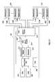
- FIG. 10shows a meter electronics in accordance with at least some embodiments
- FIG. 11shows a meter electronics in accordance with alternative embodiments.
- FIG. 12shows a method in accordance with at least some embodiments.
- the terms “including” and “comprising”are used in an open-ended fashion, and thus should be interpreted to mean “including, but not limited to . . . .”
- the term “couple” or “couples”is intended to mean either an indirect or direct connection. Thus, if a first device couples to a second device, that connection may be through a direct connection, or through an indirect connection via other devices and connections.
- Non-planarin reference to multiple pairs of transducers (or chords of the respective pairs of transducers) shall mean that the multiple pairs of transducers (or their respective chords) do not reside within the same plane.
- Spool piece and/or “meter body”shall refer to a component milled from a single casting.
- a spool piece and/or meter body created from separate castings coupled togethere.g., flange connection, welded
- Axial position of a transducer pairshall refer to the location of the upstream transducer relative to the central axis of the central passage.
- two transducer pairsmay be at the same axial position, yet on opposite sides of the spool piece.
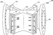
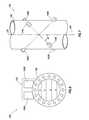
- FIG. 1illustrates a flow meter 100 comprising a sufficient number of transducer pairs that redundant flow measurements can be made.
- the meter body or spool piece 102is configured for placement between sections of a pipeline, such as by connecting the spool piece 102 to the pipeline by way of the flanges 104 A and 104 B.
- the spool piece 102has a predetermined size and defines a central passage 106 through which measured fluid flows.
- the flow meter 100further comprises a plurality of transducer pairs. In the perspective view of FIG. 1 , only one transducer of each of the illustrative eight transducer pairs is visible.
- transducer 108 A in housing 110is paired with a transducer (not visible) in housing 112 .
- transducer 114 B in housing 116is paired with a transducer (not visible) in housing 118 .
- the remaining transducers in housing 116are paired with transducers (not visible) in housing 118 .
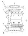
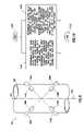
- FIG. 2illustrates an overhead partial cut-away view of the system of FIG. 1 .
- FIG. 2shows that an illustrative pair of transducers 108 A and 108 B is located along the length of spool piece 102 .
- Transducers 108 A and 108 Bare acoustic transceivers, and more particularly ultrasonic transceivers, meaning that they both generate and receive acoustic energy having frequencies of above about 20 kilohertz.
- the acoustic energyis generated and received by a piezoelectric element in each transducer.
- the piezoelectric elementis stimulated electrically by way of a sinusoidal signal, and it responds by vibrating.
- the vibration of the piezoelectric elementgenerates the acoustic signal that travels through the measured fluid in the central passage 106 to the corresponding transducer of the transducer pair.
- the receiving piezoelectric elementvibrates and generates an electrical signal that is detected, digitized, and analyzed by electronics associated with the meter.
- a path 120exists between illustrative transducers 108 A and 108 B at an angle ⁇ to a centerline 122 .
- the length of chord 120is the distance between the face of transducer 108 A and the face of transducer 108 B.
- a fluide.g., crude oil, natural gas, liquefied natural gas
- downstream transducer 108 Bgenerates an acoustic signal that propagates across the fluid in the spool piece 102 , and is then incident upon and detected by upstream transducer 108 A.
- the upstream transducer 108 Agenerates a return acoustic signal that propagates back across the fluid in the spool piece 102 , and is then incident upon and detected by the downstream transducer 108 B.
- illustrative transducers 108 A and 108 Bplay “pitch and catch” with acoustic signals along chordal path 120 . During operation, this sequence may occur thousands of times per minute.
- the transit time of the acoustic signal between transducers 108 A and 108 Bdepends in part upon whether the acoustic signal is traveling upstream or downstream with respect to the fluid flow.
- the transit time for an acoustic signal traveling downstreami.e., in the same direction as the fluid flow, defined by arrow 150 ) is less than its transit time when traveling upstream (i.e., against the fluid flow, opposite the direction of arrow 150 ).
- the upstream and downstream transit timescan be used to calculate the average flow velocity of the gas along and/or proximate to the chord, and the transit times can be used to calculate speed of sound in the measured fluid.
- the flow meter 100performs two separate and independent flow measurements with transducers on the same spool piece.
- four of the illustrative eight transducer pairsare associated with a first flow measurement subsystem, and the remaining four of the illustrative eight transducer pairs are associated with a second flow measurement subsystem.
- greater or fewer numbers of transducers pairsmay be used by each measurement subsystem, and the number of transducers pairs as between the measurement subsystems need not be the same.
- the second flow measurement subsystemmay continue to be used for measuring the fluid flow.
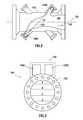
- FIG. 3illustrates an elevational end view of one end of the flow meter 100 in relation to a first measurement subsystem.
- the first flow measurement subsystem of FIG. 3comprises four chordal pathways A, B, C and D at varying elevations within the spool piece 102 .
- chord Ais an upper-most chord
- chord Bis an upper-middle chord
- chord Cis the lower-middle chord
- chord Dis the lower-most chord.
- the elevation designations upper and lower, and the variants,are in reference to gravity.
- Each chordal pathway A-Dcorresponds to a transducer pair behaving alternately as a transmitter and receiver. Also shown in FIG.
- FIG. 3is meter electronics 152 that acquire and process the data from the illustrative four chordal pathways A-D (and possibly others). Hidden from view in FIG. 3 , because of the flange, are the four pairs of transducers that correspond to chordal pathways A-D. FIG. 3 shows only the elevational orientation of the illustrative four chords of the first measurement subsystem, and does not speak to whether those chords are parallel or co-planar.
- every chord for a measurement subsystemis co-planar with other chords of the measurement subsystem, and the planes as between the two measurement subsystems form an “X” pattern.
- the inventors of the present specificationhave found that co-planar chords for each measurement subsystem result, in some situations, in measurement differences as between the subsystems that are not attributable to errors or faults with the transducers or metering electronics.
- the inventors of the present specificationhave found that cross-flow within the central passage leads to differences in measured flow as between two measurement subsystems even when the subsystems are each working properly. Such differences may lead to discrepancies in total volume, and may result in attempts to diagnose and repair non-existent problems with the flow meter.
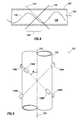
- FIG. 4illustrates an overhead cross-sectional view of a spool piece 102 with a measured fluid flowing therein. While the flow of the fluid is generally in the direction 150 , in some situations (e.g., downstream of an elbow or “T” connection) the fluid tends to take a zig-zag pattern through the central passage 106 , as illustrated by line 130 . The zig-zag pattern is exaggerated for purposes of describing the phenomenon.
- all the transducer pairs for a measurement subsystemare parallel and co-planar. For example, all the transducer pairs for a first measurement subsystem are within a vertical plane, such as the vertical plane 132 . The vertical plane 132 is shown as a line because in the view of FIG.
- the planeextends upward out of the page, and thus the view of FIG. 4 is directly along the plane.
- All the transducer pairs of a second measurement subsystemare also within a vertical plane, such as vertical plane 134 .
- vertical plane 134is shown as a line because in the view of FIG. 4 the plane extends upward out of the page, and thus the view of FIG. 4 is directly along the plane.
- chords of a measurement subsystemare co-planar, the chords are particularly sensitive to cross-flow of the measured fluid. For example, the portion of the fluid flow at 136 crosses the central passage approximately parallel to the chords of the first measurement subsystem in vertical plane 132 . The chords within plane 132 will measure significantly greater fluid flow than the chords of the second measurement subsystem whose chords are within vertical plane 134 because the flow in illustrative FIG. 3 is almost perpendicular to the vertical plane 134 .
- the two measurement subsystemswill measure different fluid flow.
- the relationship of the flow to the vertical planes 132 and 134is exaggerated, but nevertheless illustrates the point that in situations where cross-flow is present in the meter, and where the chords of a measurement subsystem are all co-planar, each measurement subsystem is particularly sensitive to cross-flow.
- FIG. 5shows an overhead view of the flow meter 100 (with the housings 110 , 112 , 116 and 118 not shown) to illustrate the relationships of the chords of a first measurement subsystem in accordance with the various embodiments.
- a first pair of transducers 108 A and 108 B(which corresponds to the upper-most chord, chord A) defines a chordal pathway at a non-perpendicular angle ⁇ to centerline 122 of spool piece 102 .
- transducers 154 A and 154 B(which corresponds to upper-middle chord, chord B) defines a chordal pathway that loosely forms the shape of an “X” with respect to the chordal pathway of transducers 108 A and 108 B, and in some embodiments the chordal pathway for transducers 154 A and 154 B is perpendicular to the chordal pathway for transducers 108 A and 108 B.
- a third pair of transducer 156 A and 156 B(which corresponds to the lower-middle chord, chord C) defines a chordal pathway parallel to the chordal pathway for transducers 108 A and 108 B, but lower in the central passage than the chordal pathway for either transducers 108 A and 108 B or transducers 154 A and 154 B.
- a fourth pair of transducers 158(transducer 158 B shown in FIG. 1 ) (which corresponds to the lower-most chord, chord D) defines a chordal pathway parallel to the chordal pathway for transducer ports 154 A and 154 B.
- the pairs of transducersare arranged such that the upper two pairs of transducers corresponding to chords A and B form an the shape of an “X”, and the lower two pairs of transducers corresponding to chords C and D also form the shape of an “X”.
- Chords A and Bare non-planar
- chords C and Dare non-planar
- chords A and Care parallel
- chords B and Dare parallel.
- the first measurement subsystemdetermines the velocity of the gas proximate to each chord A-D to obtain chordal flow velocities, and the chordal flow velocities are combined to determine an average flow velocity across the entire central passage.
- the amount of gas flowing in the spool piece, and thus the pipelinemay be determined by the first measurement system. Because the chords of the first measurement subsystem form an “X”, the effect of cross-flow on the flow measurement is reduced as the effect cancels or averages out.
- FIG. 6illustrates an elevational end view of one end of the flow meter 100 in relation to a second measurement subsystem.
- the flow measurement subsystem of FIG. 6comprises four chordal pathways E, F G and H at varying elevations within the spool piece 102 .
- chord Eis an upper-most chord
- chord Fis an upper-middle chord
- chord Gis the lower-middle chord
- chord His the lower-most chord.
- Each chordal path E-Hcorresponds to a transducer pair behaving alternately as a transmitter and receiver.
- meter electronics 152that acquire and process the data from the illustrative four chordal pathways E-H (and possibly others). Hidden from view in FIG.
- chords E-Hare at the same elevations as chords A-D, respectively, while in other embodiments some or all of the chords E-H may be at different elevations than chords A-D.
- FIG. 6shows only the elevational orientation of the illustrative four chords of the second measurement subsystem, and does not speak to whether those chords are parallel or co-planar.
- FIG. 7shows an overhead view of the flow meter 100 (with the housings 110 , 112 , 116 and 118 not shown) to illustrate another aspect of the relationship of the chordal pathways used for the second flow measurement subsystem.
- a first pair of transducers 114 A and 114 B(which corresponds to the upper-most chord, chord E) defines a chrodal pathway at a non-perpendicular angle ⁇ to centerline 122 of spool piece 102 .
- Another pair of transducers 160 A and 160 B(which corresponds to upper-middle chord, chord F) defines a chordal pathway that loosely forms the shape of an “X” with respect to the chordal pathway of transducers 114 A and 114 B.
- a third pair of transducer 162 A and 162 B(which corresponds to the lower-middle chord, chord G) defines a chordal pathway parallel to the chordal pathway for transducers 114 A and 114 B, but lower in the central passage than the chordal pathway for either transducers 114 A and 114 B or transducers 160 A and 160 B.
- a fourth pair of transducers 164(transducer 164 A shown in FIG. 1 ) (which corresponds to the lower-most chord, chord H) that defines a chordal pathway parallel to the chordal pathway for transducer ports 160 A and 160 B.
- the pairs of transducersare arranged such that the upper two pairs of transducers corresponding to chords E and F form an the shape of an “X”, and the lower two pairs of transducers corresponding to chords G and H also form the shape of an “X”.
- Chords E and Fare non-planar
- chords G and Hare non-planar
- chords E and Gare parallel
- chords F and Hare parallel.
- the second measurement subsystemdetermines the velocity of the gas proximate to each chord E-H to obtain chordal flow velocities, and the chordal flow velocities are combined to determine an average flow velocity across the entire central passage. From the average flow velocity and the cross-sectional area of the central passage, the amount of fluid flowing in the spool piece, and thus the pipeline, may be determined by the second measurement subsystem.
- FIGS. 5 and 7only show transducers associated with the measurement subsystem being described.
- FIG. 8shows an overhead view of the flow meter 100 (with the housings 110 , 112 , 116 and 118 not shown) to illustrate the relationship of at least some the transducer pairs as between measurement subsystems, and in accordance with at least some embodiments.
- the first measurement subsystemcomprises transducer pair 108 A and 108 B, transducer pair 154 A and 154 B, and two other pairs not visible in FIG. 8 .
- the second measurement subsystemcomprises transducer pair 114 A and 114 B, transducer pair 160 A and 160 B, and two other pairs not visible in FIG. 8 .
- FIG. 8shows an overhead view of the flow meter 100 (with the housings 110 , 112 , 116 and 118 not shown) to illustrate the relationship of at least some the transducer pairs as between measurement subsystems, and in accordance with at least some embodiments.
- the first measurement subsystemcomprises transducer pair 108 A and
- the transducer pairs corresponding to the upper-most chordsare at the same axial position of the spool piece 102 .
- the transducer pairs corresponding to the upper-middle chordsare at the same axial position of the spool piece 102 .
- one or more chords from each measurement subsystemmay intersect within the central passage.
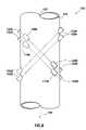
- FIG. 9shows an overhead view of the flow meter 100 (with the housings 110 , 112 , 116 and 118 not shown) to illustrate a relationship of at least some transducer pairs in accordance with alternative embodiments.
- corresponding chords as between the measurement subsystemse.g., B and F
- the transducer pairs as between the measurement subsystemshave different axial positions.
- the transducer pair 108 A and 108 B(corresponding to chord A) is positioned on the spool piece 102 at an axial position upstream from the transducer pair 114 A and 114 B (corresponding to chord E).
- chord Ecorresponding to chord E
- FIG. 9illustrates that corresponding transducer pairs need not be on opposite sides of the spool piece 102 .
- transducer pair 108 A and 108 Band transducer pair 114 A and 114 B.
- the upstream transducers 108 A and 114 Aare shown on the same side of the spool piece 102 , where in previously discussed embodiments the transducers were placed on opposite sides of the spool piece 102 .
- each measurement subsystemhas a separate and independent set of control electronics.
- the overall meter electronics 152 in those figuresis illustrated as two separate control electronics 152 A and 152 B.
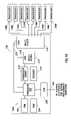
- FIG. 10illustrates control electronics 152 A associated with a single measurement subsystem. It will be understood, however, that in embodiments where each measurement subsystem has a separate and independent set of control electronics, the description in reference to FIG. 10 is equally applicable to the control electronics for each measurement subsystem.
- the control electronics 152 Amay reside with an electronics enclosure, which electronics enclosure may couple to the spool piece 102 .
- the electronics enclosure that houses the control electronics 152 Amay be equivalently mounted proximate (i.e., within a few feet) of the spool piece.
- the control electronics 152 Acomprise a processor 202 coupled to a random access memory (RAM) 204 , read only memory (ROM) 206 and a communication port (COM) 208 .
- the processor 202is the device within which programs execute to perform measurement of fluid flow through central passage for the particular measurement subsystem.
- the ROM 206is a non-volatile memory which stores operating system programs, as well as programs to implement measuring fluid flow.
- the RAM 204is the working memory for the processor 202 , and before execution some programs and/or data structures may be copied from the ROM 206 to the RAM 204 .
- programs and data structuresmay be accessed directly from the ROM 206 .
- the communication port 208is the mechanism by which the meter communicates with other devices, such as the control electronics associated with the other measurement subsystems of the flow meter, flow computers (which may accumulate measured flow volumes from a plurality of flow meters) and/or a data acquisition system. While the processor 202 , RAM 204 , ROM 206 and communication port 208 are illustrated as individual devices, in alternative embodiments microcontrollers are used, which microcontrollers integrally comprise a processing core, RAM, ROM and communication ports.
- Processor 202further couples to and controls a plurality of devices in order to send and receive acoustic signals through the measured fluid.
- the processor 202couples to a transducer driver 210 , receiver 212 , and two multiplexers 214 and 216 by way of control lines 218 and 220 , respectively.
- the transducer driver 210comprises an oscillator circuit and an amplifier circuit.
- the transducer driver 210creates an initial signal, amplifies the signal to sufficient signal strength to drive a transducer, and provides impedance matching with respect to the transducers.
- the transducer driverreceives an alternating current (AC) signal of the desired frequency from the processor 202 , amplifies the signal and provides impedance matching with respect to the transducers.
- the receiver 212likewise may take many forms.
- the receiver 212is an analog-to-digital converter which takes the analog waveform created by a transducer representative of the received acoustic energy, and converts the signal to digital form.
- the receiver 212may filter and/or amplify the signals prior to or after digitization. The digitized version of the received signal may then pass to the processor 202 for purposes of determining fluid flow.
- the processor 202executing a program, selectively controls the multiplexers 214 and 216 to couple each transducer of each transducer pair to the transducer driver 210 (to drive the transducer to create the acoustic signal) and to the receiver 212 (to receive the electrical signal created by the transducer in response to the acoustic energy).
- the processor 202within the span of an illustrative one second measurement period, directs each transducer pair to send approximately 30 upstream acoustic signals and 30 downstream acoustic signals. Greater or fewer sets of upstream and downstream acoustic signals for each transducer pair, and longer or shorter measurement periods, may be equivalently used.
- transducer 108 Ais the sending transducer
- transducer 108 Bis the receiving transducer; however, in actual operation these roles change alternately.
- the transducer driver 210is coupled, through multiplexers 214 and 216 , to the transducer 108 A.
- An electrical signal generated and/or amplified by the transducer driver 210propagates to and excites a piezoelectric element in transducer 108 A, and in turn transducer 108 A generates an acoustic signal.
- the acoustic signaltraverses the distance between transducer 108 A and transducer 108 B in the measured fluid.
- the transducer pair 108 A and 108 Bis not aligned, but in operation the transducer pair would be substantially coaxial, as illustrated in FIG. 5 .
- the processor 202changes the configuration of the multiplexers 214 and 216 to couple transducer 108 B to the receiver 212 .
- Transducer 108 Breceives the acoustic energy (i.e., acoustic signal and noise signals), and an electrical signal corresponding to the received acoustic energy propagates to the receiver 212 .
- a fluid flow velocity proximate to the chord corresponding to transducer pair 108 A and 108 Bis determined.
- the processor 202determines a flow velocity of the fluid in the central passage, and based on the cross-sectional area of the central passage, the processor calculates a flow volume through the meter over the measurement period.
- the control electronic 152 Acouple only to transducer pairs of the first measurement subsystem, it follows that the control electronics 152 A calculate the flow volume, or value indicative of flow volume, using only transducer pairs of the first measurement subsystem.
- control electronicsmay exchange values proportional to measured fluid flow, and when the values are different (e.g., by a predetermined threshold), one or both control electronics may assert an alarm condition.
- Asserting an alarm conditionmay involve changing a contact position on a digital output, turning on a light emitting diode (LED) or other light emitting device, or sending a message indicating the alarm condition through the COM port 208 to other devices, such as supervisory control and data acquisition (SCADA) system.
- SCADAsupervisory control and data acquisition
- FIG. 11illustrates meter electronics 152 in accordance with alternative embodiments.
- a single set of control electronics 152couples to both the transducer pairs 222 for first measurement subsystem and the transducer pairs 224 for the second measurement subsystem.
- the processor 202calculates a first value indicative of fluid flow through the meter using only the transducer pairs 222 of the first measurement subsystem.
- the processor 202also calculates a second value indicative of fluid flow through the meter using only the transducer pairs 224 of the second measurement subsystem.
- the processor 202may then compare the values, and indicate an alarm condition if the two values are different by a predetermined value.
- the processor 202 and related electronicsmay continue to calculate a value indicative of the fluid flow using transducer pairs of one measurement subsystem when one or more of the transducers of the second measurement subsystem are inoperable.
- the processor 202may refrain from comparing the two values calculated, and instead may send the two values to other devices (e.g., a flow computer, a SCADA system) for comparison by way of the COM port 208 .
- FIG. 12illustrates a method in accordance with at least some embodiments.
- the methodstarts (block 1200 ) and proceeds to determining a first value indicative of flow volume of fluid through a central passage of a meter body (the determining using a first plurality of transducer pairs, each transducer pair defines a chord, and at least two of the chords are non-planar) (block 1204 ).
- the methodfurther comprises determining a second value indicative of flow volume of fluid through the central passage of the meter body (the determining using a second plurality of transducer pairs, each transducer pair of the second plurality of transducer pairs defines a chord, and at least two of the chords are non-planar) (block 1208 ), and the method ends (block 1212 ).
Landscapes
- Physics & Mathematics (AREA)
- Electromagnetism (AREA)
- Fluid Mechanics (AREA)
- General Physics & Mathematics (AREA)
- Measuring Volume Flow (AREA)
- Organic Low-Molecular-Weight Compounds And Preparation Thereof (AREA)
Abstract
Description
Claims (15)
Priority Applications (9)
| Application Number | Priority Date | Filing Date | Title |
|---|---|---|---|
| US12/169,685US7752919B2 (en) | 2008-07-09 | 2008-07-09 | System and method of an acoustic flow meter with dual flow measurements |
| CN2009801197692ACN102047081B (en) | 2008-07-09 | 2009-06-09 | System and method of acoustic flow meter with dual flow measurements |
| BRPI0912799ABRPI0912799B8 (en) | 2008-07-09 | 2009-06-09 | ACOUSTIC FLOW METER, AND, METHOD WITH DOUBLE FLOW MEASUREMENTS |
| RU2011104585/28ARU2484430C2 (en) | 2008-07-09 | 2009-06-09 | Flow meter |
| MX2010012571AMX2010012571A (en) | 2008-07-09 | 2009-06-09 | System and method of an acoustic flow meter with dual flow measurements. |
| HUE09794876AHUE031501T2 (en) | 2008-07-09 | 2009-06-09 | System and method of an acoustic flow meter with dual flow measurements |
| CA2721971ACA2721971C (en) | 2008-07-09 | 2009-06-09 | System and method of an acoustic flow meter with dual flow measurements |
| PCT/US2009/046752WO2010005669A2 (en) | 2008-07-09 | 2009-06-09 | System and method of an acoustic flow meter with dual flow measurements |
| EP09794876.4AEP2310809B1 (en) | 2008-07-09 | 2009-06-09 | System and method of an acoustic flow meter with dual flow measurements |
Applications Claiming Priority (1)
| Application Number | Priority Date | Filing Date | Title |
|---|---|---|---|
| US12/169,685US7752919B2 (en) | 2008-07-09 | 2008-07-09 | System and method of an acoustic flow meter with dual flow measurements |
Publications (2)
| Publication Number | Publication Date |
|---|---|
| US20100005900A1 US20100005900A1 (en) | 2010-01-14 |
| US7752919B2true US7752919B2 (en) | 2010-07-13 |
Family
ID=41503921
Family Applications (1)
| Application Number | Title | Priority Date | Filing Date |
|---|---|---|---|
| US12/169,685Active2028-09-22US7752919B2 (en) | 2008-07-09 | 2008-07-09 | System and method of an acoustic flow meter with dual flow measurements |
Country Status (9)
| Country | Link |
|---|---|
| US (1) | US7752919B2 (en) |
| EP (1) | EP2310809B1 (en) |
| CN (1) | CN102047081B (en) |
| BR (1) | BRPI0912799B8 (en) |
| CA (1) | CA2721971C (en) |
| HU (1) | HUE031501T2 (en) |
| MX (1) | MX2010012571A (en) |
| RU (1) | RU2484430C2 (en) |
| WO (1) | WO2010005669A2 (en) |
Cited By (14)
| Publication number | Priority date | Publication date | Assignee | Title |
|---|---|---|---|---|
| US20100113197A1 (en)* | 2008-11-05 | 2010-05-06 | Arachnid, Inc. | Virtual shuffleboard |
| US20110277558A1 (en)* | 2010-05-12 | 2011-11-17 | Sick Engineering Gmbh | Ultrasound measurement of the flow speed of a fluid in a conduit |
| US20120060944A1 (en)* | 2010-09-09 | 2012-03-15 | Sick Engineering Gmbh | Method and apparatus for measuring a gas flow velocity |
| US20120227496A1 (en)* | 2009-11-19 | 2012-09-13 | Endress + Hauser Flowtec Ag | Measuring Device |
| CN103383277A (en)* | 2012-05-02 | 2013-11-06 | 丹尼尔测量和控制公司 | Instrument replacing system for flowmeters specific to collaborative arrangement |
| WO2013166239A1 (en)* | 2012-05-02 | 2013-11-07 | Daniel Measurement And Control, Inc. | Temperature verification for ultrasonic flow meters |
| US9010196B2 (en) | 2012-06-22 | 2015-04-21 | Krohne Ag | Flow-rate measurement system |
| US9316517B2 (en) | 2011-09-23 | 2016-04-19 | Daniel Measurement And Control, Inc. | System and method for combining co-located flowmeters |
| US20160202098A1 (en)* | 2014-01-13 | 2016-07-14 | Cameron International Corporation | Acoustic Flow Measurement Device Including a Plurality of Chordal Planes Each Having a Plurality of Axial Velocity Measurements Using Transducer Pairs |
| US20160216145A1 (en)* | 2013-09-12 | 2016-07-28 | Endress + Hauser Flowtec Ag | Measuring tube for a flow measuring device and flow measuring device |
| US20180010942A1 (en)* | 2016-07-05 | 2018-01-11 | Sick Engineering Gmbh | Ultrasound measuring apparatus and method for measuring the flow rate of a fluid |
| US10161909B2 (en) | 2015-10-29 | 2018-12-25 | Mustang Sampling Llc | Steady state fluid flow verification for sample takeoff |
| US11144078B2 (en) | 2019-09-23 | 2021-10-12 | Mustang Sampling, Llc | Adjustable multistage pressure reducing regulator |
| US12105537B2 (en) | 2019-09-23 | 2024-10-01 | Mustang Sampling, Llc | Adjustable multistage pressure reducing regulator with augmented thermal control |
Families Citing this family (10)
| Publication number | Priority date | Publication date | Assignee | Title |
|---|---|---|---|---|
| US7752919B2 (en)* | 2008-07-09 | 2010-07-13 | Daniel Measurement And Control, Inc. | System and method of an acoustic flow meter with dual flow measurements |
| US7735380B2 (en)* | 2008-07-09 | 2010-06-15 | Daniel Measurement & Control, Inc. | Method and system of coordination of measurement subsystems of a flow meter |
| CN102538912B (en)* | 2011-11-17 | 2014-04-16 | 中国计量科学研究院 | Method for analyzing additive errors of flow field of ultrasonic flowmeter |
| USD689784S1 (en)* | 2012-06-15 | 2013-09-17 | General Electric Company | Flow cell for a flow meter |
| USD705102S1 (en)* | 2013-04-17 | 2014-05-20 | General Electric Company | Flow cell for a flow meter |
| ES2950657T3 (en)* | 2017-01-17 | 2023-10-11 | Rubicon Res Pty Ltd | Flow measurement |
| CN107478716B (en)* | 2017-07-06 | 2020-07-28 | 中国船舶重工集团公司第七一九研究所 | Detection device and detection method for gas-liquid two-phase distribution field in boiler |
| CN110793581A (en)* | 2019-11-12 | 2020-02-14 | 韩云学 | Ultrasonic flowmeter system for flow measurement of main water supply pipeline of nuclear power station |
| CN112903046B (en)* | 2019-11-19 | 2025-06-13 | 卡姆鲁普股份有限公司 | Modular Ultrasonic Consumption Meter |
| CN114993396B (en)* | 2022-07-14 | 2023-03-14 | 美核电气(济南)股份有限公司 | High-precision multichannel liquid ultrasonic flowmeter suitable for high-temperature medium |
Citations (30)
| Publication number | Priority date | Publication date | Assignee | Title |
|---|---|---|---|---|
| US2993373A (en)* | 1956-09-18 | 1961-07-25 | Kritz Jack | Ultrasonic flowmeters and transducers therefor |
| US3564912A (en) | 1968-10-28 | 1971-02-23 | Westinghouse Electric Corp | Fluid flow measurement system |
| US3625057A (en)* | 1967-11-01 | 1971-12-07 | Mitsubishi Electric Corp | Ultrasonic flowmeter |
| US3940985A (en)* | 1975-04-18 | 1976-03-02 | Westinghouse Electric Corporation | Fluid flow measurement system for pipes |
| US4024760A (en) | 1975-07-25 | 1977-05-24 | Westinghouse Electric Corporation | Fluid flow measurement apparatus |
| US4102186A (en)* | 1976-07-23 | 1978-07-25 | E. I. Du Pont De Nemours And Company | Method and system for measuring flow rate |
| JPS5539035A (en) | 1978-09-14 | 1980-03-18 | Fuji Electric Co Ltd | Ultrasonic flow meter |
| US4320666A (en)* | 1978-07-22 | 1982-03-23 | Redding Robert J | Fluid flow measuring apparatus |
| US4408589A (en)* | 1974-08-31 | 1983-10-11 | Robert Bosch Gmbh | Process and apparatus for operating an internal combustion engine |
| JPS59104026U (en) | 1982-12-29 | 1984-07-13 | 富士電機株式会社 | ultrasonic flow meter |
| US4646575A (en) | 1983-05-11 | 1987-03-03 | British Gas Corporation | Ultrasonic flowmeter |
| US5040415A (en)* | 1990-06-15 | 1991-08-20 | Rockwell International Corporation | Nonintrusive flow sensing system |
| US5228347A (en)* | 1991-10-18 | 1993-07-20 | Ore International, Inc. | Method and apparatus for measuring flow by using phase advance |
| US5369998A (en)* | 1989-12-12 | 1994-12-06 | Commonwealth Scientific And Industrial Research Organisation | Ultrasonic mass flow meter for solids suspended in a gas stream |
| US5437194A (en)* | 1991-03-18 | 1995-08-01 | Panametrics, Inc. | Ultrasonic transducer system with temporal crosstalk isolation |
| JPH08304435A (en) | 1995-05-12 | 1996-11-22 | Kaijo Corp | Ultrasonic wind-velocity measuring system inside tunnel |
| US5597962A (en)* | 1995-03-31 | 1997-01-28 | Caldon, Inc. | Apparatus for determining fluid flow |
| US5962790A (en) | 1995-06-07 | 1999-10-05 | Panametrics, Inc. | Ultrasonic path bundle and systems |
| US6089104A (en)* | 1996-05-27 | 2000-07-18 | Chang; Hak Soo | Ultrasonic flow meter using transit time across tube chords for determining the flow rates |
| US20020053243A1 (en)* | 2000-09-15 | 2002-05-09 | Su Tyan Khak | Ultrasonic flow measuring method |
| US6435038B1 (en)* | 2000-04-24 | 2002-08-20 | Chang Min Tech Co., Ltd. | Ultrasonic flow velocity measuring apparatus |
| US6435037B1 (en) | 2000-01-06 | 2002-08-20 | Data Sciences International, Inc. | Multiplexed phase detector |
| US6550345B1 (en)* | 2000-09-11 | 2003-04-22 | Daniel Industries, Inc. | Technique for measurement of gas and liquid flow velocities, and liquid holdup in a pipe with stratified flow |
| US6595071B1 (en)* | 2000-01-06 | 2003-07-22 | Transoma Medical, Inc. | Estimation of error angle in ultrasound flow measurement |
| US6732595B2 (en)* | 2002-07-18 | 2004-05-11 | Panametrics, Inc. | Method of and system for determining the mass flow rate of a fluid flowing in a conduit |
| US7151490B2 (en) | 2000-03-29 | 2006-12-19 | Time Domain Corporation | System and method for estimating separation distance between impulse radios using impulse signal amplitude |
| US7152490B1 (en)* | 2005-08-15 | 2006-12-26 | Daniel Measurement And Control, Inc. | Methods for determining transducer delay time and transducer separation in ultrasonic flow meters |
| US7290455B2 (en)* | 2005-08-22 | 2007-11-06 | Daniel Measurement And Control, Inc. | Driver configuration for an ultrasonic flow meter |
| US20100005900A1 (en)* | 2008-07-09 | 2010-01-14 | Daniel Measurement And Control, Inc. | System and Method of an Acoustic Flow Meter With Dual Flow Measurements |
| US20100005901A1 (en)* | 2008-07-09 | 2010-01-14 | Daniel Measurement And Control, Inc. | Method and system of coordination of measurement subsystems of a flow meter |
Family Cites Families (5)
| Publication number | Priority date | Publication date | Assignee | Title |
|---|---|---|---|---|
| JPH0834435A (en)* | 1994-07-21 | 1996-02-06 | Sanyu Kogyo Kk | Side wall member for housing box and assembly mechanism therefor |
| US5719329B1 (en)* | 1995-12-28 | 1999-11-16 | Univ Ohio | Ultrasonic measuring system and method of operation |
| US6047602A (en)* | 1996-10-29 | 2000-04-11 | Panametrics, Inc. | Ultrasonic buffer/waveguide |
| US6925891B2 (en)* | 2002-04-30 | 2005-08-09 | Matsushita Electric Industrial Co., Ltd. | Ultrasonic flowmeter and method of measuring flow volume |
| US8336394B2 (en)* | 2008-01-10 | 2012-12-25 | Metering & Technology Sas | Device for measuring the flow rate of a fluid flowing in a pipe |
- 2008
- 2008-07-09USUS12/169,685patent/US7752919B2/enactiveActive
- 2009
- 2009-06-09RURU2011104585/28Apatent/RU2484430C2/enactive
- 2009-06-09CACA2721971Apatent/CA2721971C/enactiveActive
- 2009-06-09CNCN2009801197692Apatent/CN102047081B/enactiveActive
- 2009-06-09BRBRPI0912799Apatent/BRPI0912799B8/enactiveIP Right Grant
- 2009-06-09MXMX2010012571Apatent/MX2010012571A/enactiveIP Right Grant
- 2009-06-09WOPCT/US2009/046752patent/WO2010005669A2/enactiveApplication Filing
- 2009-06-09EPEP09794876.4Apatent/EP2310809B1/enactiveActive
- 2009-06-09HUHUE09794876Apatent/HUE031501T2/enunknown
Patent Citations (31)
| Publication number | Priority date | Publication date | Assignee | Title |
|---|---|---|---|---|
| US2993373A (en)* | 1956-09-18 | 1961-07-25 | Kritz Jack | Ultrasonic flowmeters and transducers therefor |
| US3625057A (en)* | 1967-11-01 | 1971-12-07 | Mitsubishi Electric Corp | Ultrasonic flowmeter |
| US3564912A (en) | 1968-10-28 | 1971-02-23 | Westinghouse Electric Corp | Fluid flow measurement system |
| US4408589A (en)* | 1974-08-31 | 1983-10-11 | Robert Bosch Gmbh | Process and apparatus for operating an internal combustion engine |
| US3940985A (en)* | 1975-04-18 | 1976-03-02 | Westinghouse Electric Corporation | Fluid flow measurement system for pipes |
| US4024760A (en) | 1975-07-25 | 1977-05-24 | Westinghouse Electric Corporation | Fluid flow measurement apparatus |
| US4102186A (en)* | 1976-07-23 | 1978-07-25 | E. I. Du Pont De Nemours And Company | Method and system for measuring flow rate |
| US4320666A (en)* | 1978-07-22 | 1982-03-23 | Redding Robert J | Fluid flow measuring apparatus |
| JPS5539035A (en) | 1978-09-14 | 1980-03-18 | Fuji Electric Co Ltd | Ultrasonic flow meter |
| JPS59104026U (en) | 1982-12-29 | 1984-07-13 | 富士電機株式会社 | ultrasonic flow meter |
| US4646575A (en) | 1983-05-11 | 1987-03-03 | British Gas Corporation | Ultrasonic flowmeter |
| US5369998A (en)* | 1989-12-12 | 1994-12-06 | Commonwealth Scientific And Industrial Research Organisation | Ultrasonic mass flow meter for solids suspended in a gas stream |
| US5040415A (en)* | 1990-06-15 | 1991-08-20 | Rockwell International Corporation | Nonintrusive flow sensing system |
| US5437194A (en)* | 1991-03-18 | 1995-08-01 | Panametrics, Inc. | Ultrasonic transducer system with temporal crosstalk isolation |
| US5228347A (en)* | 1991-10-18 | 1993-07-20 | Ore International, Inc. | Method and apparatus for measuring flow by using phase advance |
| US5597962A (en)* | 1995-03-31 | 1997-01-28 | Caldon, Inc. | Apparatus for determining fluid flow |
| JPH08304435A (en) | 1995-05-12 | 1996-11-22 | Kaijo Corp | Ultrasonic wind-velocity measuring system inside tunnel |
| US5962790A (en) | 1995-06-07 | 1999-10-05 | Panametrics, Inc. | Ultrasonic path bundle and systems |
| US6089104A (en)* | 1996-05-27 | 2000-07-18 | Chang; Hak Soo | Ultrasonic flow meter using transit time across tube chords for determining the flow rates |
| US6435037B1 (en) | 2000-01-06 | 2002-08-20 | Data Sciences International, Inc. | Multiplexed phase detector |
| US6595071B1 (en)* | 2000-01-06 | 2003-07-22 | Transoma Medical, Inc. | Estimation of error angle in ultrasound flow measurement |
| US7151490B2 (en) | 2000-03-29 | 2006-12-19 | Time Domain Corporation | System and method for estimating separation distance between impulse radios using impulse signal amplitude |
| US6435038B1 (en)* | 2000-04-24 | 2002-08-20 | Chang Min Tech Co., Ltd. | Ultrasonic flow velocity measuring apparatus |
| US6550345B1 (en)* | 2000-09-11 | 2003-04-22 | Daniel Industries, Inc. | Technique for measurement of gas and liquid flow velocities, and liquid holdup in a pipe with stratified flow |
| US6460419B2 (en)* | 2000-09-15 | 2002-10-08 | International Hydrosonic Co., Ltd. | Ultrasonic flow measuring method |
| US20020053243A1 (en)* | 2000-09-15 | 2002-05-09 | Su Tyan Khak | Ultrasonic flow measuring method |
| US6732595B2 (en)* | 2002-07-18 | 2004-05-11 | Panametrics, Inc. | Method of and system for determining the mass flow rate of a fluid flowing in a conduit |
| US7152490B1 (en)* | 2005-08-15 | 2006-12-26 | Daniel Measurement And Control, Inc. | Methods for determining transducer delay time and transducer separation in ultrasonic flow meters |
| US7290455B2 (en)* | 2005-08-22 | 2007-11-06 | Daniel Measurement And Control, Inc. | Driver configuration for an ultrasonic flow meter |
| US20100005900A1 (en)* | 2008-07-09 | 2010-01-14 | Daniel Measurement And Control, Inc. | System and Method of an Acoustic Flow Meter With Dual Flow Measurements |
| US20100005901A1 (en)* | 2008-07-09 | 2010-01-14 | Daniel Measurement And Control, Inc. | Method and system of coordination of measurement subsystems of a flow meter |
Non-Patent Citations (6)
| Title |
|---|
| Dr. Volker Herrmann, Mr. John Lansing, Mr. Toralf Dietz & Mr. Steve Caldwell; Investigations of an 8-Path Ultrasound Meter-What Sensitivity to Upstream Disturbances Remain? 6th South East Asia Hydrocarbon Flow Measurement Workshop 2007; 21 pp. |
| Gregor Brown, Herb Estrada, Don Augenstein, & Terry Cousins, LNG Allocation Metering Using 8-Path Ultrasonic Meters; 25th North Sea Flow Measurement Workshop-Oct. 16-19, 2007, 23 pp. |
| International Search Report for PCT Patent Application No. PCT/US2009/046752 filed Jun. 9, 2009. |
| Internationl Search Report for PCT Patent Application No. PCT/US2009/046711 filed Jun. 9, 2009. |
| Notice of Allowance and Fee(s) Due for U.S. Appl. No. 12/169,678-filed Jul. 9, 2008-dated Apr. 13, 2010. |
| Notice of Allowance and Fee(s) Due for U.S. Appl. No. 12/169,678-filed Jul. 9, 2008-dated Feb. 2, 2010. |
Cited By (31)
| Publication number | Priority date | Publication date | Assignee | Title |
|---|---|---|---|---|
| US8342925B2 (en)* | 2008-11-05 | 2013-01-01 | Arachnid, Inc. | Simulated game apparatus of a virtual shuffleboard with detection system for a real puck |
| US20100113197A1 (en)* | 2008-11-05 | 2010-05-06 | Arachnid, Inc. | Virtual shuffleboard |
| US8904861B2 (en)* | 2009-11-19 | 2014-12-09 | Endress + Hauser Flowtec Ag | Measuring device |
| US20120227496A1 (en)* | 2009-11-19 | 2012-09-13 | Endress + Hauser Flowtec Ag | Measuring Device |
| US20110277558A1 (en)* | 2010-05-12 | 2011-11-17 | Sick Engineering Gmbh | Ultrasound measurement of the flow speed of a fluid in a conduit |
| US8234934B2 (en)* | 2010-05-12 | 2012-08-07 | Sick Engineering Gmbh | Ultrasound measurement of the flow speed of a fluid in a conduit |
| US20120060944A1 (en)* | 2010-09-09 | 2012-03-15 | Sick Engineering Gmbh | Method and apparatus for measuring a gas flow velocity |
| US8245582B2 (en)* | 2010-09-09 | 2012-08-21 | Sick Engineering Gmbh | Method and apparatus for measuring a gas flow velocity |
| US9316517B2 (en) | 2011-09-23 | 2016-04-19 | Daniel Measurement And Control, Inc. | System and method for combining co-located flowmeters |
| CN103383277B (en)* | 2012-05-02 | 2015-12-30 | 丹尼尔测量和控制公司 | For the system and method that the instrument of the flowmeter for cooperative arrangement is replaced |
| US8974114B2 (en) | 2012-05-02 | 2015-03-10 | Daniel Measurement And Control, Inc. | Temperature verification for ultrasonic flow meters |
| US9097568B2 (en) | 2012-05-02 | 2015-08-04 | Daniel Measurement And Control, Inc. | System and method for meter substitution for co-located flowmeters |
| WO2013166244A1 (en)* | 2012-05-02 | 2013-11-07 | Daniel Measurement And Control, Inc. | System and method for meter substitution for co-located flowmeters |
| CN103383277A (en)* | 2012-05-02 | 2013-11-06 | 丹尼尔测量和控制公司 | Instrument replacing system for flowmeters specific to collaborative arrangement |
| RU2590318C2 (en)* | 2012-05-02 | 2016-07-10 | ДЭНИЭЛ МЕЖЕМЕНТ энд КОНТРОЛ, ИНК. | Verification of temperature of ultrasonic flow meters |
| WO2013166239A1 (en)* | 2012-05-02 | 2013-11-07 | Daniel Measurement And Control, Inc. | Temperature verification for ultrasonic flow meters |
| US9010196B2 (en) | 2012-06-22 | 2015-04-21 | Krohne Ag | Flow-rate measurement system |
| US9574926B2 (en)* | 2013-09-12 | 2017-02-21 | Endress + Hauser Flowtec Ag | Measuring tube for a flow measuring device and flow measuring device |
| US20160216145A1 (en)* | 2013-09-12 | 2016-07-28 | Endress + Hauser Flowtec Ag | Measuring tube for a flow measuring device and flow measuring device |
| US10928230B2 (en) | 2014-01-13 | 2021-02-23 | Sensia Llc | Acoustic flow measurement device including a plurality of chordal planes each having a plurality of axial velocity measurements using transducer pairs |
| US10288462B2 (en)* | 2014-01-13 | 2019-05-14 | Cameron Industrial Corporation | Acoustic flow measurement device including a plurality of chordal planes each having a plurality of axial velocity measurements using transducer pairs |
| US20160202098A1 (en)* | 2014-01-13 | 2016-07-14 | Cameron International Corporation | Acoustic Flow Measurement Device Including a Plurality of Chordal Planes Each Having a Plurality of Axial Velocity Measurements Using Transducer Pairs |
| US10161909B2 (en) | 2015-10-29 | 2018-12-25 | Mustang Sampling Llc | Steady state fluid flow verification for sample takeoff |
| US10684259B2 (en) | 2015-10-29 | 2020-06-16 | Mustang Sampling, LLC. | Steady state fluid flow verification for sample takeoff |
| US11536694B2 (en) | 2015-10-29 | 2022-12-27 | Mustang Sampling, Llc | Steady state fluid flow verification for sample takeoff |
| US20180010942A1 (en)* | 2016-07-05 | 2018-01-11 | Sick Engineering Gmbh | Ultrasound measuring apparatus and method for measuring the flow rate of a fluid |
| US10260919B2 (en)* | 2016-07-05 | 2019-04-16 | Sick Engineering Gmbh | Ultrasound measuring apparatus and method for measuring the flow rate of a fluid |
| US11144078B2 (en) | 2019-09-23 | 2021-10-12 | Mustang Sampling, Llc | Adjustable multistage pressure reducing regulator |
| US11573582B2 (en) | 2019-09-23 | 2023-02-07 | Mustang Sampling, Llc | Adjustable multistage pressure reducing regulator |
| US11971733B2 (en) | 2019-09-23 | 2024-04-30 | Mustang Sampling, Llc | Adjustable multistage pressure reducing regulator |
| US12105537B2 (en) | 2019-09-23 | 2024-10-01 | Mustang Sampling, Llc | Adjustable multistage pressure reducing regulator with augmented thermal control |
Also Published As
| Publication number | Publication date |
|---|---|
| WO2010005669A2 (en) | 2010-01-14 |
| BRPI0912799B1 (en) | 2019-11-19 |
| BRPI0912799A2 (en) | 2015-10-13 |
| EP2310809A4 (en) | 2012-10-31 |
| HUE031501T2 (en) | 2017-07-28 |
| MX2010012571A (en) | 2010-12-14 |
| CN102047081B (en) | 2013-10-23 |
| RU2011104585A (en) | 2012-08-20 |
| CA2721971C (en) | 2013-01-22 |
| US20100005900A1 (en) | 2010-01-14 |
| EP2310809A2 (en) | 2011-04-20 |
| CN102047081A (en) | 2011-05-04 |
| BRPI0912799B8 (en) | 2022-08-30 |
| CA2721971A1 (en) | 2010-01-14 |
| EP2310809B1 (en) | 2016-10-19 |
| WO2010005669A3 (en) | 2010-03-11 |
| RU2484430C2 (en) | 2013-06-10 |
Similar Documents
| Publication | Publication Date | Title |
|---|---|---|
| US7752919B2 (en) | System and method of an acoustic flow meter with dual flow measurements | |
| US7735380B2 (en) | Method and system of coordination of measurement subsystems of a flow meter | |
| CA2716489C (en) | Method and system of determining forthcoming failure of transducers | |
| CA2605943C (en) | Method and ultrasonic meter system for determining pipe roughness | |
| AU2013256254B2 (en) | Temperature verification for ultrasonic flow meters | |
| CA2721966C (en) | Method and system of detecting liquid in an acoustic flow meter | |
| US7624616B2 (en) | Meter proving method and system | |
| CA2712451C (en) | Method and system of determining a pattern of arrival time cycle skip in an acoustic flow meter | |
| BRPI0615188B1 (en) | METHOD, SYSTEM, AND, ULTRASONIC FLOWMETER |
Legal Events
| Date | Code | Title | Description |
|---|---|---|---|
| AS | Assignment | Owner name:DANIEL MEASUREMENT AND CONTROL, INC., TEXAS Free format text:ASSIGNMENT OF ASSIGNORS INTEREST;ASSIGNORS:STRAUB, HENRY CHARLES, JR., DR.;DERR, CHARLES W.;REEL/FRAME:021210/0072 Effective date:20080707 | |
| STCF | Information on status: patent grant | Free format text:PATENTED CASE | |
| RR | Request for reexamination filed | Effective date:20110221 | |
| B1 | Reexamination certificate first reexamination | Free format text:THE PATENTABILITY OF CLAIMS 8-11 IS CONFIRMED. CLAIMS 1, 4 AND 12 ARE DETERMINED TO BE PATENTABLE AS AMENDED. CLAIMS 2, 3, 5-7 AND 13-15, DEPENDENT ON AN AMENDED CLAIM, ARE DETERMINED TO BE PATENTABLE. NEW CLAIM 16 IS ADDED AND DETERMINED TO BE PATENTABLE. | |
| FPAY | Fee payment | Year of fee payment:4 | |
| MAFP | Maintenance fee payment | Free format text:PAYMENT OF MAINTENANCE FEE, 8TH YEAR, LARGE ENTITY (ORIGINAL EVENT CODE: M1552) Year of fee payment:8 | |
| MAFP | Maintenance fee payment | Free format text:PAYMENT OF MAINTENANCE FEE, 12TH YEAR, LARGE ENTITY (ORIGINAL EVENT CODE: M1553); ENTITY STATUS OF PATENT OWNER: LARGE ENTITY Year of fee payment:12 | |
| AS | Assignment | Owner name:EMERSUB CVIII, INC., MISSOURI Free format text:ASSIGNMENT OF ASSIGNORS INTEREST;ASSIGNOR:DANIEL MEASUREMENT AND CONTROL, LLC;REEL/FRAME:061661/0840 Effective date:20200724 Owner name:DANIEL MEASUREMENT AND CONTROL, LLC, TEXAS Free format text:CERTIFICATE OF CONVERSION AND NAME CHANGE;ASSIGNOR:DANIEL MEASUREMENT AND CONTROL, INC.;REEL/FRAME:061661/0777 Effective date:20200724 Owner name:MICRO MOTION, INC., COLORADO Free format text:MERGER;ASSIGNOR:EMERSUB CVIII, INC.;REEL/FRAME:061661/0952 Effective date:20200724 |