US7752821B2 - Suspended ceiling system - Google Patents
Suspended ceiling systemDownload PDFInfo
- Publication number
- US7752821B2 US7752821B2US11/257,726US25772605AUS7752821B2US 7752821 B2US7752821 B2US 7752821B2US 25772605 AUS25772605 AUS 25772605AUS 7752821 B2US7752821 B2US 7752821B2
- Authority
- US
- United States
- Prior art keywords
- grid system
- clip
- tube
- opposed faces
- primary carrier
- Prior art date
- Legal status (The legal status is an assumption and is not a legal conclusion. Google has not performed a legal analysis and makes no representation as to the accuracy of the status listed.)
- Active, expires
Links
Images


Classifications
- E—FIXED CONSTRUCTIONS
- E04—BUILDING
- E04B—GENERAL BUILDING CONSTRUCTIONS; WALLS, e.g. PARTITIONS; ROOFS; FLOORS; CEILINGS; INSULATION OR OTHER PROTECTION OF BUILDINGS
- E04B9/00—Ceilings; Construction of ceilings, e.g. false ceilings; Ceiling construction with regard to insulation
- E04B9/06—Ceilings; Construction of ceilings, e.g. false ceilings; Ceiling construction with regard to insulation characterised by constructional features of the supporting construction, e.g. cross section or material of framework members
- E04B9/10—Connections between parallel members of the supporting construction
- E—FIXED CONSTRUCTIONS
- E04—BUILDING
- E04B—GENERAL BUILDING CONSTRUCTIONS; WALLS, e.g. PARTITIONS; ROOFS; FLOORS; CEILINGS; INSULATION OR OTHER PROTECTION OF BUILDINGS
- E04B9/00—Ceilings; Construction of ceilings, e.g. false ceilings; Ceiling construction with regard to insulation
- E04B9/06—Ceilings; Construction of ceilings, e.g. false ceilings; Ceiling construction with regard to insulation characterised by constructional features of the supporting construction, e.g. cross section or material of framework members
- E04B9/061—Ceilings; Construction of ceilings, e.g. false ceilings; Ceiling construction with regard to insulation characterised by constructional features of the supporting construction, e.g. cross section or material of framework members supporting construction for curved ceilings
- E—FIXED CONSTRUCTIONS
- E04—BUILDING
- E04B—GENERAL BUILDING CONSTRUCTIONS; WALLS, e.g. PARTITIONS; ROOFS; FLOORS; CEILINGS; INSULATION OR OTHER PROTECTION OF BUILDINGS
- E04B9/00—Ceilings; Construction of ceilings, e.g. false ceilings; Ceiling construction with regard to insulation
- E04B9/06—Ceilings; Construction of ceilings, e.g. false ceilings; Ceiling construction with regard to insulation characterised by constructional features of the supporting construction, e.g. cross section or material of framework members
- E04B9/065—Ceilings; Construction of ceilings, e.g. false ceilings; Ceiling construction with regard to insulation characterised by constructional features of the supporting construction, e.g. cross section or material of framework members comprising supporting beams having a folded cross-section
- E04B9/067—Ceilings; Construction of ceilings, e.g. false ceilings; Ceiling construction with regard to insulation characterised by constructional features of the supporting construction, e.g. cross section or material of framework members comprising supporting beams having a folded cross-section with inverted T-shaped cross-section
- E04B9/068—Ceilings; Construction of ceilings, e.g. false ceilings; Ceiling construction with regard to insulation characterised by constructional features of the supporting construction, e.g. cross section or material of framework members comprising supporting beams having a folded cross-section with inverted T-shaped cross-section with double web
- E—FIXED CONSTRUCTIONS
- E04—BUILDING
- E04B—GENERAL BUILDING CONSTRUCTIONS; WALLS, e.g. PARTITIONS; ROOFS; FLOORS; CEILINGS; INSULATION OR OTHER PROTECTION OF BUILDINGS
- E04B9/00—Ceilings; Construction of ceilings, e.g. false ceilings; Ceiling construction with regard to insulation
- E04B9/06—Ceilings; Construction of ceilings, e.g. false ceilings; Ceiling construction with regard to insulation characterised by constructional features of the supporting construction, e.g. cross section or material of framework members
- E04B9/12—Connections between non-parallel members of the supporting construction
- E04B9/127—Connections between non-parallel members of the supporting construction one member being discontinuous and abutting against the other member
- E—FIXED CONSTRUCTIONS
- E04—BUILDING
- E04B—GENERAL BUILDING CONSTRUCTIONS; WALLS, e.g. PARTITIONS; ROOFS; FLOORS; CEILINGS; INSULATION OR OTHER PROTECTION OF BUILDINGS
- E04B9/00—Ceilings; Construction of ceilings, e.g. false ceilings; Ceiling construction with regard to insulation
- E04B9/06—Ceilings; Construction of ceilings, e.g. false ceilings; Ceiling construction with regard to insulation characterised by constructional features of the supporting construction, e.g. cross section or material of framework members
- E04B9/12—Connections between non-parallel members of the supporting construction
- E04B9/16—Connections between non-parallel members of the supporting construction the members lying in different planes
- E—FIXED CONSTRUCTIONS
- E04—BUILDING
- E04B—GENERAL BUILDING CONSTRUCTIONS; WALLS, e.g. PARTITIONS; ROOFS; FLOORS; CEILINGS; INSULATION OR OTHER PROTECTION OF BUILDINGS
- E04B9/00—Ceilings; Construction of ceilings, e.g. false ceilings; Ceiling construction with regard to insulation
- E04B9/18—Means for suspending the supporting construction
- Y—GENERAL TAGGING OF NEW TECHNOLOGICAL DEVELOPMENTS; GENERAL TAGGING OF CROSS-SECTIONAL TECHNOLOGIES SPANNING OVER SEVERAL SECTIONS OF THE IPC; TECHNICAL SUBJECTS COVERED BY FORMER USPC CROSS-REFERENCE ART COLLECTIONS [XRACs] AND DIGESTS
- Y10—TECHNICAL SUBJECTS COVERED BY FORMER USPC
- Y10T—TECHNICAL SUBJECTS COVERED BY FORMER US CLASSIFICATION
- Y10T403/00—Joints and connections
- Y10T403/71—Rod side to plate or side
- Y10T403/7164—One rod held between bight and other rod extending through aperture in leg of connector
- Y—GENERAL TAGGING OF NEW TECHNOLOGICAL DEVELOPMENTS; GENERAL TAGGING OF CROSS-SECTIONAL TECHNOLOGIES SPANNING OVER SEVERAL SECTIONS OF THE IPC; TECHNICAL SUBJECTS COVERED BY FORMER USPC CROSS-REFERENCE ART COLLECTIONS [XRACs] AND DIGESTS
- Y10—TECHNICAL SUBJECTS COVERED BY FORMER USPC
- Y10T—TECHNICAL SUBJECTS COVERED BY FORMER US CLASSIFICATION
- Y10T403/00—Joints and connections
- Y10T403/71—Rod side to plate or side
- Y10T403/7182—Yoke or ring-type connector
- Y10T403/7188—Rod received in open channel
- Y—GENERAL TAGGING OF NEW TECHNOLOGICAL DEVELOPMENTS; GENERAL TAGGING OF CROSS-SECTIONAL TECHNOLOGIES SPANNING OVER SEVERAL SECTIONS OF THE IPC; TECHNICAL SUBJECTS COVERED BY FORMER USPC CROSS-REFERENCE ART COLLECTIONS [XRACs] AND DIGESTS
- Y10—TECHNICAL SUBJECTS COVERED BY FORMER USPC
- Y10T—TECHNICAL SUBJECTS COVERED BY FORMER US CLASSIFICATION
- Y10T403/00—Joints and connections
- Y10T403/71—Rod side to plate or side
- Y10T403/7194—Crossed rods
Definitions
- Suspended ceilings of various shapes and sizesare being increasingly used in order to add interest to various public spaces, such as retail outlets, contemporary office lobbies and halls, entertainment establishments, and the like. This has lead to the creation of suspended ceiling systems for defining spaces in which the ceiling panels lie in more than one plane, such as in vaults, transitions between different ceiling heights, islands, and waves.
- a suspended ceiling systemis provided that is particularly suited for providing a grid system that is curved in vertical plane, provides for accurate spacing and alignment of the grid elements, and facilitates quick assembly and installation of the assembled grid system.
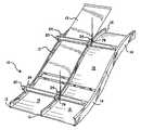
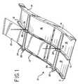
- FIG. 1is a perspective view of a grid system for a curved suspended ceiling in accordance with the present invention.
- FIG. 2is a perspective view of a portion of a primary carrier in accordance with the present invention.
- FIG. 3is a perspective view of a splice for connecting primary carriers in accordance with the present invention.
- FIG. 4is a perspective view showing the splice of FIG. 3 joining two primary carriers in accordance with present invention.
- FIG. 5is a perspective view of a portion of the grid system according to the present invention showing a clip for securing a primary carrier to a main runner.
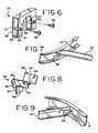
- FIG. 6is an enlarged perspective view of the clip for securing the primary carrier to the main runner.
- FIG. 7is a perspective view of a portion of the grid assembly showing a connection of a primary carrier to a perimeter trim piece.
- FIG. 8is an enlarged perspective view of a clip for securing the primary carrier to the perimeter trim piece.
- FIG. 9is a perspective view of a portion of the grid system of the present invention showing the connection of a main runner to a trim piece.
- FIG. 10is an enlarged perspective view of a clip for securing a main runner to a trim piece.
- FIG. 11is a perspective view of a portion of the grid system showing two pieces of trim connected to each other by means of a splice clip.
- FIG. 12is an enlarged exploded perspective view of the splice clip for connecting two trim pieces together.
- FIG. 13is a perspective view of a hanger clip for securing the hanger wire to the primary carrier.
- the present inventioncomprises an assembly particularly suited for a curved suspended ceiling grid.
- the systemgenerally designated 10
- the systemincludes main runners or tees 12 which are curved in a vertical plane to support either flexible panels 13 or preformed, lay-in panels (not shown), the latter requiring cross-tees between adjacent main tees.
- the curvemay be either concave or convex with respect to the exposed side of the ceiling system.
- Edge or perimeter trim pieces 14(which may be either curved or straight, as required to correspond to the shape of the main runners 12 ), having opposed interior slots define the perimeter of the suspended ceiling. Corner clips are used to secure the perimeter trim pieces to each other. However, the perimeter trim may be omitted, if desired, without departing from the invention.
- Each of the main runners, trim pieces and corner clipshave previously been available from Chicago Metallic Corporation, assignee of the present application, under the “CurvGrid” and “CurvTrim” trademarks.
- one or more primary or tube carriersis utilized to interconnect the main runners 10 and provide a unitized, rigid grid system.
- Each primary carrier 20preferably extends substantially the full width of the suspended ceiling and is preferably spaced no more than about 48 inches from the adjacent primary carrier.
- the primary carrier 20may be of any length that is practical given both manufacturing and shipping constraints, and typically may be as long as 16 feet in length.
- the primary carrier 20preferably has a circular cross-section, with an outside diameter of approximately 1.25 inches, although other cross-sectional shapes and sizes may be utilized without departing from the invention.
- the primary carrierhas a notch or slot 22 for each of the main runners supported by the tube carrier 20 , the notch 22 being sized in width and depth to receive the bulb of the main runner.
- the tube carrier 20is roll-formed from 0.028 inch thick steel with a lock seam 20 a .
- the notches 22aid in the installation of the ceiling by maintaining on-center spacing of the main runners 10 without the use of cross tees.
- adjacent primary carrierscan be staggered so that together they extend substantially the full width of the ceiling. More preferably, one or more primary carriers may be joined together end-to-end to obtain the desired length by using a splice connector 21 , as shown in FIG. 3 . With reference to FIGS. 3 and 4 , approximately half the length of the splice connector 21 is received in the interior of each of the two primary carriers joined thereby.
- the primary carriers and splice connectormay be positively secured to one another by fasteners, such as screws 21 a .
- the primary carriers 20may also include an inwardly-projecting embossment spaced from their ends that serve as a stop to prevent over insertion of the splice clip 21 into the primary carriers 20 .
- the splice connector 21may be made from electrical metallic tube (commonly referred to as “EMT”) having an outside diameter and cross-sectional shape that is complementary to the inside diameter and cross-sectional shape of the primary carrier 20 .
- EMTelectrical metallic tube
- the splice connector 21has a slot 21 b along its length to allow it to mate with a lock seam 20 a in the tube carrier 20 , thus preventing rotation of the splice clip 21 and maintaining the angular alignment of the splice clip relative to the primary carriers 20 .
- clips 24 with cut-outs 26are provided that fit over the top of the primary carrier 20 to secure the main runners 10 to the primary carrier 20 .
- the cut-outs 26are generally complementary in shape to the primary carrier and thus, in the illustrated embodiment, are generally an inverted U-shape.
- the clip 24is provided with opposed faces 28 , the bottom edges 30 of which terminate in inwardly-pointing lips that are adapted to support the bottom surface of the bulb of the main runner.
- the clip 24may be formed with inwardly-pointing tabs (not shown) for the same purpose.
- the clip 24has aligned holes 34 in its opposed faces 28 for receiving screws 36 that draw together the lips or tabs on the clips so that they securely support the bulb of the main runner 10 .
- the clip 24preferably includes stand offs 37 that are received on the shanks of the screws 36 and are sized in length to prevent over-tightening for the screws.
- the primary carrierprovides a cantilevered attachment point for the perimeter trim, allowing the hanger wire for suspending the grid to stand off from the end of the carrier tube, thus shielding the hanger wire from view.
- a perimeter clip 38 for securing the primary carrier 20 to a trim piece 14is shown, best seen in FIGS. 7 and 8 .
- the primary carrier perimeter clip 38comprises three L-shaped segments 40 , 42 , 44 , joined together on one leg of the L, that are bendable into a generally U-shaped member.
- each of the outer L-shaped segmentsWhen bent, the corner 46 of one leg of each of the outer L-shaped segments is partially received in the upper of two opposed slots on the trim pieces, while the edge 48 of the corresponding leg of the middle L-shaped segment is received in the lower of the two opposed slots.
- the other leg of each L-shaped segmentextends generally perpendicularly from the trim piece 14 to support the primary carrier 20 .
- Each of the two outer arms that support the primary carrier 20includes an aperture 50 adapted to receive a screw or other fastener for positively securing the clip 38 to the primary carrier 20 .
- a second perimeter clip 52is shown for securing the main runners 10 to a perimeter trim piece. (Such clips may also be used to secure cross tees, if used, to a perimeter trim piece.)
- the main runner perimeter clip 52is also generally L-shaped, with one leg of the L having opposed edges that are received in the opposed slots of the straight trim piece 14 .
- This legpreferably includes a tapped hole 54 for receiving a set screw 56 that may be tightened against the web of the trim piece 14 to lock the perimeter clip 52 thereto.
- this leghas a curved edge 58 that permits the clip 52 to be positioned on the trim piece and then simply twisted to cause its edges to locate in the opposed slots in the trim piece.
- the other legis adapted to lie along the web of the main runner 10 , and includes an ear 60 which can be folded through a slot in the main runner 12 to lock the main runner thereto.
- a splice clip 62is provided for joining lengths of perimeter trim 14 to each other.
- the splice clip 62has two parts 64 , 66 .
- the first part 64has opposed edges 68 which are received in the opposed slots on the trim piece.
- the second piece 66overlies the first piece 64 to clamp the lips that define the slots in the trim piece between the two pieces of the splice clip 62 .
- the second piece 66has four corners 70 that are bent downwardly to engage the lips of the channels that receive the first piece 64 .
- the two pieces 64 , 66 of the splice clip 62are attached together by a pair of screws 72 .
- the grid system of the present inventionis suspended by hanger wires secured to the primary carriers, rather than to the main runners. This minimizes the number of hanger wires required to support the system.
- the curved grid system as describedcan be easily and accurately assembled on the floor of the space in which it is to be installed, and then raised as a unit in order to secure the hanger wires to the tube carriers. Otherwise, the primary carriers 20 are first hung, and the remaining components of the grid system then secured thereto.
- a plurality of hanger clips 74is provided that secure the hanger wire to the primary carriers 20 .
- the hanger clips 74have a strap portion 76 that is partially covered with a resilient, rubber-like sleeve 78 that conforms to the shape of the surface of the tube carrier 20 contacted by it.
- the hanger clips 74have a slightly oversized opening with respect to the diameter of the primary carrier in order to permit a minor amount of relative rotation between the hanger clip and the primary carrier. This ability to rotate with respect to each other allows a certain amount of “self centering” of the tube carrier with respect to the hanger wire, so that the hanger wire extends generally perpendicularly from the primary carrier. This subjects the hanger wire to less stress at the point at which it is secured to the hanger clip.
- a suspended ceiling system particularly suited for a curved gridhas been provided that facilitates accurate and quick assembly with enhanced structural rigidity.
- the inventionhas been described in terms of a preferred embodiment, it is not intended to be limited to the same. Indeed, variations are contemplated that are within the ordinary skill in the art.
- the primary carrierscould also be used with a more conventional planar grid system.
- cross teesare not required for structural reasons, they may still be utilized with the present invention for aesthetic reasons if, e.g., the lay-in panels have an edge reveal.
- the primary carriermay have a cross-section other than generally circular without departing from the invention.
Landscapes
- Engineering & Computer Science (AREA)
- Architecture (AREA)
- Physics & Mathematics (AREA)
- Electromagnetism (AREA)
- Civil Engineering (AREA)
- Structural Engineering (AREA)
- Mutual Connection Of Rods And Tubes (AREA)
Abstract
Description
Claims (12)
Priority Applications (2)
| Application Number | Priority Date | Filing Date | Title |
|---|---|---|---|
| US11/257,726US7752821B2 (en) | 2004-10-27 | 2005-10-25 | Suspended ceiling system |
| US12/816,500US8006454B2 (en) | 2004-10-27 | 2010-06-16 | Suspended ceiling system |
Applications Claiming Priority (2)
| Application Number | Priority Date | Filing Date | Title |
|---|---|---|---|
| US62241804P | 2004-10-27 | 2004-10-27 | |
| US11/257,726US7752821B2 (en) | 2004-10-27 | 2005-10-25 | Suspended ceiling system |
Related Child Applications (1)
| Application Number | Title | Priority Date | Filing Date |
|---|---|---|---|
| US12/816,500ContinuationUS8006454B2 (en) | 2004-10-27 | 2010-06-16 | Suspended ceiling system |
Publications (2)
| Publication Number | Publication Date |
|---|---|
| US20060101764A1 US20060101764A1 (en) | 2006-05-18 |
| US7752821B2true US7752821B2 (en) | 2010-07-13 |
Family
ID=36242699
Family Applications (2)
| Application Number | Title | Priority Date | Filing Date |
|---|---|---|---|
| US11/257,726Active2026-07-31US7752821B2 (en) | 2004-10-27 | 2005-10-25 | Suspended ceiling system |
| US12/816,500Active2026-02-20US8006454B2 (en) | 2004-10-27 | 2010-06-16 | Suspended ceiling system |
Family Applications After (1)
| Application Number | Title | Priority Date | Filing Date |
|---|---|---|---|
| US12/816,500Active2026-02-20US8006454B2 (en) | 2004-10-27 | 2010-06-16 | Suspended ceiling system |
Country Status (2)
| Country | Link |
|---|---|
| US (2) | US7752821B2 (en) |
| CA (1) | CA2524559C (en) |
Cited By (6)
| Publication number | Priority date | Publication date | Assignee | Title |
|---|---|---|---|---|
| US20100269447A1 (en)* | 2009-04-27 | 2010-10-28 | Nathan Schuit | Snap-on structural connector |
| US8869484B2 (en) | 2012-11-13 | 2014-10-28 | Usg Interiors, Llc | Flexible drywall grid member for framing drywall structures |
| CN105178495A (en)* | 2015-07-29 | 2015-12-23 | 浙江亚厦装饰股份有限公司 | Ceiling joist system and construction method thereof |
| US10662647B2 (en)* | 2015-09-11 | 2020-05-26 | Arktura Llc | Faceted architectural fixtures |
| US11802407B2 (en) | 2021-11-23 | 2023-10-31 | Rockwool A/S | Suspended drywall ceiling grid system support members |
| USD1047225S1 (en) | 2021-11-23 | 2024-10-15 | Rockwool A/S | Support member for a suspended ceiling |
Families Citing this family (13)
| Publication number | Priority date | Publication date | Assignee | Title |
|---|---|---|---|---|
| US7578107B2 (en)* | 2005-12-02 | 2009-08-25 | Worthington Armstrong Venture | Suspended ceiling segment |
| US8096089B2 (en) | 2008-05-06 | 2012-01-17 | Worthington Armstrong Venture | Suspended ceiling cloud with flexible panel |
| US20100095606A1 (en)* | 2008-10-16 | 2010-04-22 | Usg Interiors, Inc. | Faceted metal suspended ceiling |
| US8596009B2 (en) | 2010-11-01 | 2013-12-03 | Awi Licensing Company | Suspended ceiling system, securing members, and process of installing a suspended ceiling system |
| US9249592B2 (en)* | 2012-01-05 | 2016-02-02 | Martin Integrated Systems | Interstitial seismic resistant support for an acoustic ceiling grid |
| US8782985B2 (en)* | 2012-03-01 | 2014-07-22 | Usg Interiors, Llc | Splice clip for ceiling grid systems |
| US8763336B2 (en)* | 2012-03-01 | 2014-07-01 | Usg Interiors, Llc | Attachment clip for ceiling grid systems |
| US9175473B2 (en)* | 2013-08-19 | 2015-11-03 | Modular Arts, Inc. | Ceiling tile system |
| EP3112546B1 (en)* | 2015-07-02 | 2018-11-07 | Saint-Gobain Placo SAS | Ceiling and ceiling suspension system |
| US9938718B1 (en)* | 2017-03-02 | 2018-04-10 | Usg Interiors, Llc | Arched island ceiling useful in open plenum |
| CN108035476B (en)* | 2017-11-30 | 2023-08-18 | 广州康普顿至高建材有限公司 | Curved surface ceiling and installation method thereof |
| DE202022107262U1 (en)* | 2022-12-28 | 2024-01-18 | Erich R. Vogl | Building ceiling suspension arrangement |
| CN116427612B (en)* | 2023-05-09 | 2023-11-24 | 江苏领创新材料有限公司 | Assembly component of keel structure |
Citations (85)
| Publication number | Priority date | Publication date | Assignee | Title |
|---|---|---|---|---|
| US420293A (en)* | 1890-01-28 | Interior decoration | ||
| US555097A (en)* | 1896-02-25 | Ceiling | ||
| US2155964A (en)* | 1938-10-08 | 1939-04-25 | Permutit Co | Insulated strainer and method of fabricating same |
| US2155694A (en)* | 1937-07-24 | 1939-04-25 | L T Corp | Grating |
| US2710679A (en)* | 1950-10-24 | 1955-06-14 | John T Bibb | Suspended ceiling construction |
| US2912075A (en)* | 1953-03-28 | 1959-11-10 | Pfistershammer Josef | Support structure constructed from hollow members, more particularly tubes of thin hard-rolled metal sheets |
| US2946414A (en)* | 1959-01-20 | 1960-07-26 | Southern Extrusions Inc | Framework for a suspended ceiling |
| US3015375A (en)* | 1959-08-24 | 1962-01-02 | Robert P Lickliter | Locking connection for supporting grid systems |
| US3159251A (en) | 1961-04-24 | 1964-12-01 | Kenneth F Becker | Flexible corner molding for curved surfaces |
| US3463428A (en)* | 1967-06-20 | 1969-08-26 | Robert D Kindorf | Multi-purpose pipe clamp |
| US3798865A (en) | 1972-03-17 | 1974-03-26 | Integrated Ceilings Inc | Grid support structure and clip means therefor |
| US3911638A (en)* | 1974-04-22 | 1975-10-14 | Alcan Aluminum Corp | Vertical ceiling assembly and clip elements therefor |
| US3918234A (en)* | 1974-08-12 | 1975-11-11 | Sydney Joseph Weissman | Clip primarily for T-bar ceilings |
| US4040758A (en)* | 1975-01-24 | 1977-08-09 | Roblin Industries, Inc. | Suspended ceiling hanging clip |
| US4044428A (en)* | 1975-09-08 | 1977-08-30 | B-Line Systems, Inc. | Conduit clamp |
| US4191352A (en) | 1978-08-21 | 1980-03-04 | Fastway Fasteners, Inc. | Rotatably installed suspension clip |
| US4257205A (en) | 1979-07-16 | 1981-03-24 | United States Gypsum Company | Attachment system for suspended drywall ceiling panels |
| US4389828A (en) | 1980-06-12 | 1983-06-28 | Howmet Aluminum Corp. | Suspended ceiling system with crossing clip |
| US4417711A (en)* | 1982-05-17 | 1983-11-29 | Robroy Industries | Pipe hanger |
| US4479341A (en)* | 1982-04-02 | 1984-10-30 | Fastway Fasteners, Inc. | Clips for T-bar grid ceiling arrangement |
| US4494350A (en) | 1982-09-20 | 1985-01-22 | Ceiling Dynamics, Inc. | Aluminum suspension system |
| US4559751A (en)* | 1984-03-01 | 1985-12-24 | Crystaplex Plastics Ltd. | Corrosive resistant grid construction for a suspended ceiling |
| US4580386A (en) | 1981-12-14 | 1986-04-08 | Armstrong World Industries, Inc. | Expansion clip on a ceiling runner |
| US4583340A (en)* | 1984-05-03 | 1986-04-22 | Donn Incorporated | Fixture support clip for suspension ceiling grid systems |
| US4610562A (en) | 1985-08-29 | 1986-09-09 | Chicago Metallic Corporation | Perimeter clip |
| US4630423A (en) | 1984-12-24 | 1986-12-23 | United States Elevator Corporation | Suspended-ceiling framework assembly |
| US4640077A (en) | 1983-01-21 | 1987-02-03 | Intalite International N.V. | Clip for a suspended ceiling |
| US4641987A (en) | 1985-06-28 | 1987-02-10 | Schlegel Gary R | Clip for suspended ceiling gridwork |
| US4715161A (en) | 1986-05-19 | 1987-12-29 | Erico International Corporation | Suspended ceiling grid clip |
| US4761930A (en)* | 1981-12-14 | 1988-08-09 | Fibergrate Corporation | Grating system |
| US4794745A (en)* | 1986-12-15 | 1989-01-03 | National Rolling Mills Inc. | Tier drop grid system |
| US4850172A (en) | 1986-04-25 | 1989-07-25 | Alcan Aluminum Corporation | Ceiling or like structural system and splice member therefor |
| US4927103A (en)* | 1988-11-14 | 1990-05-22 | Nicholson Richard J | Method and apparatus for piping support |
| US4932170A (en) | 1989-06-30 | 1990-06-12 | Spear Matthew L | Valuted sub-ceiling illumination system |
| US4989387A (en)* | 1989-08-24 | 1991-02-05 | Chicago Metallic Corporation | Ceiling system with staked on connectors |
| US5024404A (en)* | 1987-10-19 | 1991-06-18 | Ballard Estus E | Pipe clamp for overhead sprinkler heads and the like |
| US5046294A (en) | 1990-05-14 | 1991-09-10 | National Rolling Mills, Inc. | Perimeter clip |
| US5077951A (en) | 1990-10-31 | 1992-01-07 | Baker Metal Products, Inc. | Suspended ceiling system |
| US5088261A (en) | 1990-12-20 | 1992-02-18 | Usg Interiors, Inc. | Curved grid tees for suspension ceilings |
| US5137390A (en) | 1992-01-16 | 1992-08-11 | E.H. Price Limited | Connection means for suspended ceiling grid |
| US5149221A (en) | 1991-12-04 | 1992-09-22 | Cgc Inc. | Angled connection of suspended ceiling tees |
| US5154031A (en) | 1991-03-26 | 1992-10-13 | Schilling Components, Incorporated | Suspended ceiling system and connector clip therefor |
| US5201787A (en) | 1991-05-31 | 1993-04-13 | Usg Interiors, Inc. | Trim system for suspension ceilings |
| US5214900A (en)* | 1991-05-28 | 1993-06-01 | Cornelius Folkerts | Method and means for supporting overhead joists to create greater headroom |
| US5234654A (en)* | 1992-02-27 | 1993-08-10 | Brooks Clifford D | Concrete forming system |
| US5271202A (en) | 1992-05-12 | 1993-12-21 | Chicago Metallic Corporation | Suspended ceiling system with staked-on connectors |
| US5313759A (en)* | 1991-12-18 | 1994-05-24 | Chase Iii Francis H | Cleanroom ceiling system |
| US5413300A (en)* | 1992-05-13 | 1995-05-09 | Hosteing; Guy | Profiles for supporting and maintaining in tension a false ceiling or a false wall |
| US5435514A (en)* | 1992-06-12 | 1995-07-25 | Fan Tex, Inc. | Fan hanger support for drop ceilings |
| US5572844A (en)* | 1995-04-24 | 1996-11-12 | Armstrong World Industries, Inc. | Runner-trim connector |
| US5619833A (en)* | 1995-01-26 | 1997-04-15 | Neff; Eric S. | Suspended ceiling system |
| US5839246A (en) | 1996-09-12 | 1998-11-24 | Worthington Armstrong Venture | Grid framework for suspended ceiling |
| US5839703A (en)* | 1997-02-27 | 1998-11-24 | Perfection Corporation | Anti-rotation bracket |
| US5901524A (en)* | 1997-08-27 | 1999-05-11 | Wright; Jerauld George | Grid-like building panel framework and members for making such panel framework |
| US5911664A (en)* | 1996-05-29 | 1999-06-15 | Advanced Industrial & Marine Services | Fastening system for securing composite gratings to structural members |
| US5927037A (en) | 1992-10-19 | 1999-07-27 | T & T Fixings Limited | Construction of suspended ceilings, walls, and partition walls |
| US5937605A (en)* | 1998-02-18 | 1999-08-17 | Usg Interiors, Inc. | Adjustable face trim clip for drywall suspension grid |
| US6018923A (en) | 1997-12-16 | 2000-02-01 | Usg Interiors, Inc. | Transition clip for drywall suspension grid |
| US6047517A (en)* | 1998-03-30 | 2000-04-11 | 3244 Corporation | Hanger for hanging electrical fixture from suspended ceiling |
| US6047512A (en)* | 1998-10-21 | 2000-04-11 | Usg Interiors, Inc. | Drywall suspension grid system |
| US6047511A (en) | 1998-03-04 | 2000-04-11 | Usg Interiors, Inc. | Grid tee with integrally stitched web |
| US6105216A (en)* | 1999-02-25 | 2000-08-22 | Hydra-Zorb Co. | Clamp assembly |
| US6138425A (en) | 1997-12-16 | 2000-10-31 | Usg Interiors, Inc. | Splice clip for drywall suspension grid |
| US6199343B1 (en) | 1999-04-19 | 2001-03-13 | Worthington Armstrong Venture | Connector assembly for ceiling grid |
| US6230464B1 (en)* | 2000-03-02 | 2001-05-15 | 3244 Corporation | Electrical box hanger |
| US6260810B1 (en)* | 1999-08-16 | 2001-07-17 | Dong-A Flexible Metal Tubes Co., Ltd. | Sprinkler mounting device |
| US6305139B1 (en) | 1998-08-01 | 2001-10-23 | Worthington Armstrong Venture | Beam clip |
| US6318042B1 (en)* | 2000-05-09 | 2001-11-20 | Ecophon Ab | Grid system for a suspended ceiling |
| US6374564B1 (en)* | 2000-05-31 | 2002-04-23 | Usg Interiors, Inc. | Suspended curved ceiling system |
| US6402096B1 (en)* | 1997-11-06 | 2002-06-11 | Sioux Chief Mfg. Co., Inc. | Apparatus for supporting conduit between building members |
| US20020152704A1 (en) | 2001-02-15 | 2002-10-24 | Thompson Eugene W. | Ceiling panel and support system |
| US6523313B2 (en) | 2001-03-06 | 2003-02-25 | Worthington Armstrong Venture | Main beam connection |
| US6598361B2 (en)* | 2001-08-20 | 2003-07-29 | Raymond M. L. Ting | Mullion splice joint design |
| US20030177735A1 (en)* | 2002-02-06 | 2003-09-25 | Gary Seeba | Built-up beam assembly for building structures |
| US20030200719A1 (en) | 2002-04-30 | 2003-10-30 | Koski Gerald L. | Main tee splice |
| US20030205016A1 (en)* | 2002-01-10 | 2003-11-06 | Peder Gulbrandsen | Free form ceiling |
| US20030226322A1 (en) | 2002-06-10 | 2003-12-11 | Worthington Armstrong Venture | Grid for a suspended ceiling |
| US20030230043A1 (en)* | 2002-06-14 | 2003-12-18 | Likozar Martin E. | Scalable suspension system for dome shaped ceilings |
| US6763641B1 (en)* | 2002-07-02 | 2004-07-20 | Usg Interiors, Inc. | Gridless free form plank ceiling |
| US20050217194A1 (en)* | 2004-03-30 | 2005-10-06 | Eric Krantz-Lilienthal | Trim system for a suspended ceiling |
| US20060016145A1 (en)* | 2004-07-23 | 2006-01-26 | Lonneman Deborah M | Curved ceiling panel |
| US20060096219A1 (en)* | 2004-09-07 | 2006-05-11 | Ingratta Anthony D | Seismic perimeter clip for suspended ceiling grid |
| USD538148S1 (en)* | 2005-07-29 | 2007-03-13 | Thomas & Betts International, Inc. | Pipe clamp |
| US7223052B1 (en)* | 2002-04-22 | 2007-05-29 | Evans Daniel D | Conduit retainer apparatus |
| US20070130869A1 (en)* | 2005-12-02 | 2007-06-14 | Worthington Armstrong Venture | Suspended ceiling segment |
Family Cites Families (13)
| Publication number | Priority date | Publication date | Assignee | Title |
|---|---|---|---|---|
| US630423A (en)* | 1899-03-17 | 1899-08-08 | Henry Stolze Jr | Candle-holder for christmas trees. |
| US855924A (en)* | 1906-06-30 | 1907-06-04 | Robert W Beaton | Fastener for pipe and conduit supports. |
| US858140A (en)* | 1906-07-03 | 1907-06-25 | Robert W Beaton | Hanger. |
| US949576A (en)* | 1909-09-16 | 1910-02-15 | Robert C Hunter | Pipe-hanger. |
| US2240592A (en)* | 1938-10-29 | 1941-05-06 | Wilson Edwin Bird | Prefabricated housing |
| US3329387A (en)* | 1965-06-25 | 1967-07-04 | Harry G Fischer | Support assembly for fixtures or the like |
| US3782065A (en)* | 1972-02-25 | 1974-01-01 | W Griffing | Ceiling mounting arrangement |
| US4452025A (en)* | 1979-07-18 | 1984-06-05 | Lew Hyok S | Self-interlocking grille |
| US4580387A (en)* | 1984-12-12 | 1986-04-08 | Crystaplex Plastics, Ltd. | Corrosive resistant grid construction for a suspended ceiling |
| US5349800A (en)* | 1993-04-19 | 1994-09-27 | Peng Sen Ming | Ceiling frame joint structure |
| US6851238B2 (en)* | 2002-03-14 | 2005-02-08 | Robert J. Rebman | Ceiling grid system and method of assembling the same |
| CA2404535A1 (en)* | 2002-09-20 | 2004-03-20 | Canam Manac Group Inc. | Composite floor system |
| US7506845B2 (en)* | 2006-10-05 | 2009-03-24 | Kofulso Co., Ltd | Stock bar and horizontal bar coupling device for mounting sprinkler |
- 2005
- 2005-10-25USUS11/257,726patent/US7752821B2/enactiveActive
- 2005-10-26CACA2524559Apatent/CA2524559C/enactiveActive
- 2010
- 2010-06-16USUS12/816,500patent/US8006454B2/enactiveActive
Patent Citations (88)
| Publication number | Priority date | Publication date | Assignee | Title |
|---|---|---|---|---|
| US420293A (en)* | 1890-01-28 | Interior decoration | ||
| US555097A (en)* | 1896-02-25 | Ceiling | ||
| US2155694A (en)* | 1937-07-24 | 1939-04-25 | L T Corp | Grating |
| US2155964A (en)* | 1938-10-08 | 1939-04-25 | Permutit Co | Insulated strainer and method of fabricating same |
| US2710679A (en)* | 1950-10-24 | 1955-06-14 | John T Bibb | Suspended ceiling construction |
| US2912075A (en)* | 1953-03-28 | 1959-11-10 | Pfistershammer Josef | Support structure constructed from hollow members, more particularly tubes of thin hard-rolled metal sheets |
| US2946414A (en)* | 1959-01-20 | 1960-07-26 | Southern Extrusions Inc | Framework for a suspended ceiling |
| US3015375A (en)* | 1959-08-24 | 1962-01-02 | Robert P Lickliter | Locking connection for supporting grid systems |
| US3159251A (en) | 1961-04-24 | 1964-12-01 | Kenneth F Becker | Flexible corner molding for curved surfaces |
| US3463428A (en)* | 1967-06-20 | 1969-08-26 | Robert D Kindorf | Multi-purpose pipe clamp |
| US3798865A (en) | 1972-03-17 | 1974-03-26 | Integrated Ceilings Inc | Grid support structure and clip means therefor |
| US3911638A (en)* | 1974-04-22 | 1975-10-14 | Alcan Aluminum Corp | Vertical ceiling assembly and clip elements therefor |
| US3918234A (en)* | 1974-08-12 | 1975-11-11 | Sydney Joseph Weissman | Clip primarily for T-bar ceilings |
| US4040758A (en)* | 1975-01-24 | 1977-08-09 | Roblin Industries, Inc. | Suspended ceiling hanging clip |
| US4044428A (en)* | 1975-09-08 | 1977-08-30 | B-Line Systems, Inc. | Conduit clamp |
| US4191352A (en) | 1978-08-21 | 1980-03-04 | Fastway Fasteners, Inc. | Rotatably installed suspension clip |
| US4257205A (en) | 1979-07-16 | 1981-03-24 | United States Gypsum Company | Attachment system for suspended drywall ceiling panels |
| US4389828A (en) | 1980-06-12 | 1983-06-28 | Howmet Aluminum Corp. | Suspended ceiling system with crossing clip |
| US4580386A (en) | 1981-12-14 | 1986-04-08 | Armstrong World Industries, Inc. | Expansion clip on a ceiling runner |
| US4761930A (en)* | 1981-12-14 | 1988-08-09 | Fibergrate Corporation | Grating system |
| US4479341A (en)* | 1982-04-02 | 1984-10-30 | Fastway Fasteners, Inc. | Clips for T-bar grid ceiling arrangement |
| US4417711A (en)* | 1982-05-17 | 1983-11-29 | Robroy Industries | Pipe hanger |
| US4494350A (en) | 1982-09-20 | 1985-01-22 | Ceiling Dynamics, Inc. | Aluminum suspension system |
| US4640077A (en) | 1983-01-21 | 1987-02-03 | Intalite International N.V. | Clip for a suspended ceiling |
| US4559751A (en)* | 1984-03-01 | 1985-12-24 | Crystaplex Plastics Ltd. | Corrosive resistant grid construction for a suspended ceiling |
| US4583340A (en)* | 1984-05-03 | 1986-04-22 | Donn Incorporated | Fixture support clip for suspension ceiling grid systems |
| US4630423A (en) | 1984-12-24 | 1986-12-23 | United States Elevator Corporation | Suspended-ceiling framework assembly |
| US4641987A (en) | 1985-06-28 | 1987-02-10 | Schlegel Gary R | Clip for suspended ceiling gridwork |
| US4610562A (en) | 1985-08-29 | 1986-09-09 | Chicago Metallic Corporation | Perimeter clip |
| US4850172A (en) | 1986-04-25 | 1989-07-25 | Alcan Aluminum Corporation | Ceiling or like structural system and splice member therefor |
| US4715161A (en) | 1986-05-19 | 1987-12-29 | Erico International Corporation | Suspended ceiling grid clip |
| US4794745A (en)* | 1986-12-15 | 1989-01-03 | National Rolling Mills Inc. | Tier drop grid system |
| US5024404A (en)* | 1987-10-19 | 1991-06-18 | Ballard Estus E | Pipe clamp for overhead sprinkler heads and the like |
| US4927103A (en)* | 1988-11-14 | 1990-05-22 | Nicholson Richard J | Method and apparatus for piping support |
| US4932170A (en) | 1989-06-30 | 1990-06-12 | Spear Matthew L | Valuted sub-ceiling illumination system |
| US4989387A (en)* | 1989-08-24 | 1991-02-05 | Chicago Metallic Corporation | Ceiling system with staked on connectors |
| US5046294A (en) | 1990-05-14 | 1991-09-10 | National Rolling Mills, Inc. | Perimeter clip |
| US5077951A (en) | 1990-10-31 | 1992-01-07 | Baker Metal Products, Inc. | Suspended ceiling system |
| US5088261A (en) | 1990-12-20 | 1992-02-18 | Usg Interiors, Inc. | Curved grid tees for suspension ceilings |
| US5154031A (en) | 1991-03-26 | 1992-10-13 | Schilling Components, Incorporated | Suspended ceiling system and connector clip therefor |
| US5214900A (en)* | 1991-05-28 | 1993-06-01 | Cornelius Folkerts | Method and means for supporting overhead joists to create greater headroom |
| US5201787A (en) | 1991-05-31 | 1993-04-13 | Usg Interiors, Inc. | Trim system for suspension ceilings |
| US5149221A (en) | 1991-12-04 | 1992-09-22 | Cgc Inc. | Angled connection of suspended ceiling tees |
| US5313759A (en)* | 1991-12-18 | 1994-05-24 | Chase Iii Francis H | Cleanroom ceiling system |
| US5137390A (en) | 1992-01-16 | 1992-08-11 | E.H. Price Limited | Connection means for suspended ceiling grid |
| US5234654A (en)* | 1992-02-27 | 1993-08-10 | Brooks Clifford D | Concrete forming system |
| US5271202A (en) | 1992-05-12 | 1993-12-21 | Chicago Metallic Corporation | Suspended ceiling system with staked-on connectors |
| US5413300A (en)* | 1992-05-13 | 1995-05-09 | Hosteing; Guy | Profiles for supporting and maintaining in tension a false ceiling or a false wall |
| US5435514A (en)* | 1992-06-12 | 1995-07-25 | Fan Tex, Inc. | Fan hanger support for drop ceilings |
| US5927037A (en) | 1992-10-19 | 1999-07-27 | T & T Fixings Limited | Construction of suspended ceilings, walls, and partition walls |
| US5979134A (en)* | 1995-01-26 | 1999-11-09 | Neff; Eric Scott | Suspended ceiling system |
| US5619833A (en)* | 1995-01-26 | 1997-04-15 | Neff; Eric S. | Suspended ceiling system |
| US5572844A (en)* | 1995-04-24 | 1996-11-12 | Armstrong World Industries, Inc. | Runner-trim connector |
| US5911664A (en)* | 1996-05-29 | 1999-06-15 | Advanced Industrial & Marine Services | Fastening system for securing composite gratings to structural members |
| US5839246A (en) | 1996-09-12 | 1998-11-24 | Worthington Armstrong Venture | Grid framework for suspended ceiling |
| US5839703A (en)* | 1997-02-27 | 1998-11-24 | Perfection Corporation | Anti-rotation bracket |
| US5901524A (en)* | 1997-08-27 | 1999-05-11 | Wright; Jerauld George | Grid-like building panel framework and members for making such panel framework |
| US6402096B1 (en)* | 1997-11-06 | 2002-06-11 | Sioux Chief Mfg. Co., Inc. | Apparatus for supporting conduit between building members |
| US6138425A (en) | 1997-12-16 | 2000-10-31 | Usg Interiors, Inc. | Splice clip for drywall suspension grid |
| US6018923A (en) | 1997-12-16 | 2000-02-01 | Usg Interiors, Inc. | Transition clip for drywall suspension grid |
| US5937605A (en)* | 1998-02-18 | 1999-08-17 | Usg Interiors, Inc. | Adjustable face trim clip for drywall suspension grid |
| US6047511A (en) | 1998-03-04 | 2000-04-11 | Usg Interiors, Inc. | Grid tee with integrally stitched web |
| US6047517A (en)* | 1998-03-30 | 2000-04-11 | 3244 Corporation | Hanger for hanging electrical fixture from suspended ceiling |
| US6305139B1 (en) | 1998-08-01 | 2001-10-23 | Worthington Armstrong Venture | Beam clip |
| US6047512A (en)* | 1998-10-21 | 2000-04-11 | Usg Interiors, Inc. | Drywall suspension grid system |
| US6105216A (en)* | 1999-02-25 | 2000-08-22 | Hydra-Zorb Co. | Clamp assembly |
| US6199343B1 (en) | 1999-04-19 | 2001-03-13 | Worthington Armstrong Venture | Connector assembly for ceiling grid |
| US6260810B1 (en)* | 1999-08-16 | 2001-07-17 | Dong-A Flexible Metal Tubes Co., Ltd. | Sprinkler mounting device |
| US6230464B1 (en)* | 2000-03-02 | 2001-05-15 | 3244 Corporation | Electrical box hanger |
| US6318042B1 (en)* | 2000-05-09 | 2001-11-20 | Ecophon Ab | Grid system for a suspended ceiling |
| US6374564B1 (en)* | 2000-05-31 | 2002-04-23 | Usg Interiors, Inc. | Suspended curved ceiling system |
| US20020152704A1 (en) | 2001-02-15 | 2002-10-24 | Thompson Eugene W. | Ceiling panel and support system |
| US6523313B2 (en) | 2001-03-06 | 2003-02-25 | Worthington Armstrong Venture | Main beam connection |
| US6598361B2 (en)* | 2001-08-20 | 2003-07-29 | Raymond M. L. Ting | Mullion splice joint design |
| US6834467B2 (en)* | 2002-01-10 | 2004-12-28 | Usg Interiors, Inc. | Free form ceiling |
| US20030205016A1 (en)* | 2002-01-10 | 2003-11-06 | Peder Gulbrandsen | Free form ceiling |
| US20030177735A1 (en)* | 2002-02-06 | 2003-09-25 | Gary Seeba | Built-up beam assembly for building structures |
| US7223052B1 (en)* | 2002-04-22 | 2007-05-29 | Evans Daniel D | Conduit retainer apparatus |
| US20030200719A1 (en) | 2002-04-30 | 2003-10-30 | Koski Gerald L. | Main tee splice |
| US20030226322A1 (en) | 2002-06-10 | 2003-12-11 | Worthington Armstrong Venture | Grid for a suspended ceiling |
| US20030230043A1 (en)* | 2002-06-14 | 2003-12-18 | Likozar Martin E. | Scalable suspension system for dome shaped ceilings |
| US6763641B1 (en)* | 2002-07-02 | 2004-07-20 | Usg Interiors, Inc. | Gridless free form plank ceiling |
| US20050217194A1 (en)* | 2004-03-30 | 2005-10-06 | Eric Krantz-Lilienthal | Trim system for a suspended ceiling |
| US20060016145A1 (en)* | 2004-07-23 | 2006-01-26 | Lonneman Deborah M | Curved ceiling panel |
| US20060096219A1 (en)* | 2004-09-07 | 2006-05-11 | Ingratta Anthony D | Seismic perimeter clip for suspended ceiling grid |
| USD538148S1 (en)* | 2005-07-29 | 2007-03-13 | Thomas & Betts International, Inc. | Pipe clamp |
| US20070130869A1 (en)* | 2005-12-02 | 2007-06-14 | Worthington Armstrong Venture | Suspended ceiling segment |
| US7578107B2 (en)* | 2005-12-02 | 2009-08-25 | Worthington Armstrong Venture | Suspended ceiling segment |
Non-Patent Citations (4)
| Title |
|---|
| Armstrong, Serpentina 3-Dimensional Ceiling System, date-unknown. |
| USG Curvatura 3-Dimensional System, 2001. |
| USG Drywall Suspension System, Suspension Systems for Curved Drywall Ceilings, 2002. |
| USG Introducing the Cuyrvatura Elite Ceiling System, 2000. |
Cited By (8)
| Publication number | Priority date | Publication date | Assignee | Title |
|---|---|---|---|---|
| US20100269447A1 (en)* | 2009-04-27 | 2010-10-28 | Nathan Schuit | Snap-on structural connector |
| US9057542B2 (en)* | 2009-04-27 | 2015-06-16 | Unirac, Inc. | Snap-on structural connector |
| US8869484B2 (en) | 2012-11-13 | 2014-10-28 | Usg Interiors, Llc | Flexible drywall grid member for framing drywall structures |
| CN105178495A (en)* | 2015-07-29 | 2015-12-23 | 浙江亚厦装饰股份有限公司 | Ceiling joist system and construction method thereof |
| CN105178495B (en)* | 2015-07-29 | 2017-07-28 | 浙江亚厦装饰股份有限公司 | A kind of suspended ceiling keel system and its construction method |
| US10662647B2 (en)* | 2015-09-11 | 2020-05-26 | Arktura Llc | Faceted architectural fixtures |
| US11802407B2 (en) | 2021-11-23 | 2023-10-31 | Rockwool A/S | Suspended drywall ceiling grid system support members |
| USD1047225S1 (en) | 2021-11-23 | 2024-10-15 | Rockwool A/S | Support member for a suspended ceiling |
Also Published As
| Publication number | Publication date |
|---|---|
| CA2524559C (en) | 2010-12-07 |
| CA2524559A1 (en) | 2006-04-27 |
| US8006454B2 (en) | 2011-08-30 |
| US20100242396A1 (en) | 2010-09-30 |
| US20060101764A1 (en) | 2006-05-18 |
Similar Documents
| Publication | Publication Date | Title |
|---|---|---|
| US8006454B2 (en) | Suspended ceiling system | |
| EP1885566B1 (en) | Clip for suspending a pair of main tees in parallel relation | |
| US4408262A (en) | Plaster frame for recessed lighting | |
| US8356453B2 (en) | Bracket and bridging member for metal stud wall | |
| US9663948B2 (en) | Free span ceiling grid system | |
| US6397533B1 (en) | Tile and mounting arrangement for a wall panel system | |
| US5516068A (en) | Device support bracket | |
| US6298623B1 (en) | Adjustable trim strip system | |
| US4426822A (en) | Vertical ceiling assembly and stringer therefor | |
| US8615947B2 (en) | Two-piece modular yoke | |
| US7455268B2 (en) | Hanger for fire sprinkler pipe | |
| US5033526A (en) | Office space dividing system | |
| US10174501B1 (en) | Metal baffles | |
| IE55643B1 (en) | Suspension ceiling grid system with narrow-faced grid | |
| KR101845356B1 (en) | Install ceiling panel support structure that does not require hanger | |
| US7271350B2 (en) | Surface mounted support assembly | |
| US20050000182A1 (en) | Grid framework | |
| US7191565B2 (en) | Connecting structure of an assembled type screen | |
| JP2005312164A (en) | Oblique hanging bolt mounting device | |
| US4633635A (en) | Panel installation clip | |
| JPH0247848Y2 (en) | ||
| JP2000144984A (en) | Office partition wall layout | |
| JP3634213B2 (en) | Building edge structure | |
| JPH0135046Y2 (en) | ||
| JP3355418B2 (en) | Partition mounting structure |
Legal Events
| Date | Code | Title | Description |
|---|---|---|---|
| AS | Assignment | Owner name:CHICAGO METALLIC CORPORATION, ILLINOIS Free format text:ASSIGNMENT OF ASSIGNORS INTEREST;ASSIGNORS:JANKOVEC, MR. SCOTT G.;JAHN, MR. PETER G.;SMITH, MR. THOMAS E.;REEL/FRAME:017321/0828 Effective date:20060314 | |
| STCF | Information on status: patent grant | Free format text:PATENTED CASE | |
| AS | Assignment | Owner name:CHICAGO METALLIC COMPANY LLC, ILLINOIS Free format text:MERGER;ASSIGNOR:CHICAGO METALLIC CORPORATION;REEL/FRAME:031926/0624 Effective date:20130930 | |
| FPAY | Fee payment | Year of fee payment:4 | |
| AS | Assignment | Owner name:ROCKWOOL INTERNATIONAL A/S, DENMARK Free format text:ASSIGNMENT OF ASSIGNORS INTEREST;ASSIGNOR:CHICAGO METALLIC COMPANY LLC;REEL/FRAME:034769/0054 Effective date:20150109 | |
| MAFP | Maintenance fee payment | Free format text:PAYMENT OF MAINTENANCE FEE, 8TH YEAR, LARGE ENTITY (ORIGINAL EVENT CODE: M1552) Year of fee payment:8 | |
| MAFP | Maintenance fee payment | Free format text:PAYMENT OF MAINTENANCE FEE, 12TH YEAR, LARGE ENTITY (ORIGINAL EVENT CODE: M1553); ENTITY STATUS OF PATENT OWNER: LARGE ENTITY Year of fee payment:12 | |
| AS | Assignment | Owner name:ROCKWOOL A/S, DENMARK Free format text:CHANGE OF NAME;ASSIGNOR:ROCKWOOL INTERNATIONAL A/S;REEL/FRAME:064087/0340 Effective date:20220411 |