US7752785B2 - License plate holder for a motor vehicle - Google Patents
License plate holder for a motor vehicleDownload PDFInfo
- Publication number
- US7752785B2 US7752785B2US11/488,664US48866406AUS7752785B2US 7752785 B2US7752785 B2US 7752785B2US 48866406 AUS48866406 AUS 48866406AUS 7752785 B2US7752785 B2US 7752785B2
- Authority
- US
- United States
- Prior art keywords
- license plate
- vehicle
- securing
- carrier plate
- screw
- Prior art date
- Legal status (The legal status is an assumption and is not a legal conclusion. Google has not performed a legal analysis and makes no representation as to the accuracy of the status listed.)
- Active, expires
Links
Images


Classifications
- B—PERFORMING OPERATIONS; TRANSPORTING
- B60—VEHICLES IN GENERAL
- B60R—VEHICLES, VEHICLE FITTINGS, OR VEHICLE PARTS, NOT OTHERWISE PROVIDED FOR
- B60R13/00—Elements for body-finishing, identifying, or decorating; Arrangements or adaptations for advertising purposes
- B60R13/10—Registration, licensing, or like devices
- B60R13/105—Licence- or registration plates, provided with mounting means, e.g. frames, holders, retainers, brackets
Definitions
- the present inventionrelates to a license plate holder for a motor vehicle for holding a vehicle license plate on the vehicle, and also to a vehicle equipped with such a license plate holder.
- the vehiclereceives a vehicle license plate which is also called a number plate.
- the vehiclesare therefore equipped with at least one license plate area in which the respective vehicle license plate can be fastened to the vehicle.
- the use of a license plate holder of the initially mentioned typeis customary. This type of license plate holder is fastened to the vehicle in the license plate area. The respective vehicle license plate is then fastened to this license plate holder and is therefore no longer directly fastened to the vehicle but only indirectly by way of the license plate holder.
- U.S. Pat. No. 3,685,188shows a vehicle license plate which is equipped with lockable fastening devices.
- the vehicle license platecan be fastened directly to the vehicle.
- the fastening devicesare designed in the manner of closing cylinders which can be changed by a key between a locked position and on open position.
- pinsare forced radially toward the outside in the locked position, whereby the latter reach behind a wall section of the vehicle. In the open position, these pins are radially adjusted so far toward the inside that the respective closing cylinder can be pulled out of the above-mentioned wall section.
- the closing cylinderis equipped with a radially projecting attachment which reaches behind a wall section of the vehicle in the locked position and, in the open position, is aligned with a slot which is arranged in the wall section and is shaped complementary to the attachment.
- the closing cylindercan be pulled out of the above-mentioned wall in the open position.
- the vehicleis equipped with corresponding closing cylinder receiving devices in the license plate area, which closing cylinder receiving devices are visible when the vehicle license plate is removed.
- the laws concerning the identification of vehiclesmay differ from one country to another. For example, different sizes of license plates may be required. Furthermore, the stipulated positioning of the respective license plate area on the vehicle may differ. The number of vehicle license plates to be mounted on the vehicle may also vary. In many countries, it is compulsory, for example, to mount one vehicle license plate respectively on the vehicle in the front as well as in the rear. Simultaneously, there are countries in which the vehicle does not have to have a vehicle license plate in the front. A license plate area, which is recognizable as such in countries in which it is not required, may impair the aesthetic impression of the vehicle.
- the present inventionaddresses the problem of indicating an advantageous method of mounting vehicle license plates on the vehicle to simplify particularly a subsequent mounting of the license plate holder on the vehicle.
- the present inventionis based on the general recognition of equipping the license plate holder with at least one fastening device which, for fastening a carrier plate provided for mounting the vehicle license plate in the license plate area on the vehicle, has a securing part which is rotatably disposed on a base part of the fastening device and, in a securing position, reaches behind a holding contour fixed to the vehicle. In a starting position of the securing part, it is freed from the holding contour and is aligned with an opening, through which the securing part can be positioned relative to the holding contour. The license plate holder can thereby be subsequently mounted on the vehicle in a particularly simple manner.
- the securing partcan be fixed in its securing position by a screw on the base part in an axial manner with respect to the axis of rotation.
- the respective fastening devicetherefore comprises, in addition to the base part which is mounted on the carrier plate and the securing part, a third part, specifically the screw by way of which the two other parts are axially fastened to one another.
- the fastening devicecan thereby be implemented in an extremely cost-effective manner.
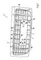
- FIG. 1is a simplified perspective top view of a motor vehicle in the area of a radiator grill
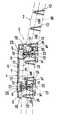
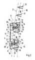
- FIG. 2is a simplified sectional view of a license plate holder along line II-II in FIG. 1 ;
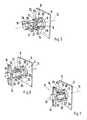
- FIG. 3is a schematic perspective view of a base part of a fastening device
- FIG. 4is a schematic perspective view of a securing part of the embodiment according to FIG. 3 ;
- FIGS. 5 to 7are schematic perspective views of the fastening device shown in FIGS. 3 and 4 under different conditions.
- FIGS. 8 to 11are schematic perspective views of another embodiment of fastening device under different conditions similar to that illustrated in FIGS. 5 and 7 .
- a vehicle 1which need only be shown here in the area of its front-end radiator grill 2 , comprises at least one license plate area designated generally by numeral 3 .
- This license plate area 3is used for mounting a known type of vehicle license plate (or number plate), which need not be shown here, on the vehicle 1 .
- the mounting of the vehicle license plate on the vehicle 1does not take place directly but indirectly by way of a license plate holder 4 that is fastened to the vehicle 1 in the license plate area 3 .
- This license plate holder 4comprises a carrier plate 5 as well as one or more fastening devices 6 .
- the carrier plate 5has a front side 7 which, in the mounted condition, faces away from the license plate area 3 , and (as better seen in FIG. 2 ) a rear side 8 which, in the mounted condition, faces the license plate area 3 .
- the carrier plate 5is dimensioned such that the respective vehicle license plate can be fastened to its front side 7 .
- the carrier plate 5can be equipped with suitable fastening devices.
- the vehicle license platecan be screwed, glued or snapped onto the carrier plate 5 .
- several, specifically, four fastening devices 6are provided in order to fasten the carrier plate 5 to the vehicle 1 .
- each fastening device 6comprises a base part 9 and a securing part 10 .
- a screw 11 with a head 12may be provided.
- the base part 9is fixedly arranged on the carrier plate 5 ; in particular, it is produced in one piece therewith.
- the fastening devices 6are constructed on the rear side 8 of the carrier plate 5 and project therefrom. Rotatably about an axis of rotation 13 , the respective securing part 10 is arranged at the respective base part 9 . At least in the mounted condition shown in FIG. 2 , with respect to each fastening device 6 , the securing part 10 is axially fixed relative to the base part 9 by the screw 11 .
- the respective securing part 10Spaced away from the carrier plate 5 , the respective securing part 10 has at least one radially projecting bracket 14 .
- the securing part 10has two such brackets 14 respectively which are diametrically arranged with respect to the rotation axis 13 .
- the respective securing part 10can be swiveled about the rotation axis 13 relative to the base part 9 between a starting position and the securing position illustrated in FIG. 2 .
- the brackets 14In the securing position, the brackets 14 each reach behind a vehicle-fixed holding contour 15 in order to fasten the carrier plate 5 to the vehicle 1 in this manner. This securing position of the securing part 10 can be secured by tightening of the screw 11 .
- the license plate area 3is preferably provided on the radiator grill 2 or on a partial area of the radiator grill 2 .
- the radiator grill 2has several vertical webs 16 and several horizontal webs 17 which form a grid characteristic of the radiator grill 2 . These struts 16 , 17 , particularly the horizontal struts 17 , form the vehicle-fixed holding contour 15 .
- the holding contour 15is formed by rear side edges of the horizontal webs 17 facing away from the carrier plate 5 .
- the license plate area 3 within the radiator grill 2will not be visible.
- the holding contours 15 formed by the horizontal webs 17are already present on the radiator grill 2 , so that the license plate area 3 will not be recognizable when the license plate holder 4 is absent.
- the securing parts 10can be rotated with respect to their base parts 9 , preferably by approximately 90 degrees.
- the brackets 14will then extend parallel to the horizontal webs 17 and, as a result, can be fitted particularly easily through the radiator slots 18 .
- These radiator slots 18are in each case framed by two adjacent vertical webs 16 and two adjacent horizontal webs 17 respectively.
- radiator grill 2Since the radiator grill 2 as a whole is available as a license plate area 3 , it is basically contemplated to mount license place brackets 4 of different sizes on the radiator grill 2 , which brackets are adapted to vehicle license plates of different sizes corresponding to legal stipulations.
- the radiator grill 2may have a curvature at least on a side facing the license plate holder 4 .
- the carrier plate 5is adapted to this curvature on its rear side 8 .
- An edge 19 of the carrier plate 5 projecting toward the rear on the rear side 8may, for example, be longer at the top than at the bottom.
- flush openings 20may be deeper at the top than at the bottom.
- the front side 7 of the carrier plate 5preferably extends in a vertical plane, so that the vehicle license plate also can be mounted in a vertically plane manner.
- FIG. 2also indicates that the screws 11 each extend coaxially with respect to the respective rotation axis 13 .
- the screws 11penetrate a respective passage opening 21 constructed in the base part 9 by way their respective shafts (not shown in detail), and are screwed into a screw opening 22 constructed on the respective securing part 10 .
- the screw heads 12are accessible from the front side 7 of the carrier plate 5 , so that the license plate holder 4 can be mounted on the vehicle 1 from the front to permit fast and simple mounting.
- the securing part 10is preferably held at the base part 9 in a captive manner, specifically even if no screw 11 is screwed in.
- This captive conditioncan preferably be implemented by a clip connection 23 which axially secures the securing part 10 on the base part 9 .
- This clip connection 23is implemented here in that the base part 9 has at least one, as illustrated, two, clip arms 24 that project axially in the direction of the securing part 10 and are radially elastic. Radially on the inside, each clip arm 24 has a clip nose 25 .
- the securing part 10is equipped with two sleeve segments 26 which radially on the outside each have a clip contour 27 . These clip contours 27 have configurations complementary to the clip noses 25 so that, when the securing part 10 is fitted in alignment with the rotation axis 13 onto the base part, the clip noses 25 reach behind the clip contours 27 .
- the base part 9is equipped with a cylinder section 28 which projects coaxially with respect to the rotation axis 13 in the direction of the securing part 10 .
- This cylinder section 28contains the passage bore 21 .
- the sleeve segments 26 of the securing part 10can be fitted onto this cylinder section 28 .
- the screw 11is absent, the securing part 10 is axially adjustably held on the base part 9 , with the sleeve segments 26 together with the sleeve section 28 forming an axial guide.
- the brackets 14each have a contact surface 29 on an underside facing the base part 9 .
- the contact surfaces 29have a shape complementary to the holding contour 15 . In this manner, the brackets 14 rest form lockingly against the holding contours in the mounted condition.
- the fastening devices 6may each have one rotation stop respectively for the securing part 10 for the starting position and for the securing position.
- At least one axial web 30may be provided on the cylinder section 28 for implementing these rotation stops.
- Two such axial webs 30are preferably provided which are arranged to be diametrically opposite with respect to the axis of rotation 13 .
- Each axial web 30projects radially from the cylinder section 28 and extends parallel to the rotation axis 13 .
- the sleeve segments 26now interact with these axial webs 30 for forming the rotation stops.
- FIG. 5in particular, in the starting position, the sleeve segments 26 come to rest in one rotating direction against the axial webs 30 and thereby form a rotation stop assigned to the starting position.
- FIGS. 6 and 7in the securing position, the sleeve segments 26 come to rest in the counter-rotating direction against the axial webs 30 and thereby form the rotation stop assigned to the securing position.
- the fastening devices 6can be equipped with a rotation lock 31 assigned to the starting position.
- the cylinder section 28can be equipped with at least one radially projecting detent nose 32 .
- two such detent noses 32are arranged diametrically opposite with respect to the rotation axis 13 .
- These detent noses 32extend, for example, parallel to the rotation axis 13 along the entire cylinder section 28 .
- the sleeve segments 26each have a detent opening 33 that has a shape complementary to that of the respective detent nose 32 ; thus here, the shape of an axial longitudinal groove.
- the starting position of the securing part 10can be secured in the not yet mounted condition in order to simplify the mounting of the license plate holder 4 .
- the rotation lock 31is therefore dimensioned such that it is overcome when the screw 11 is screwed in.
- the securing part 10can automatically be changed into the securing position by the screwing-in of the screw 11 .
- the mounting of the license plate holder 4 on the vehicleis carried out as follows.
- the securing parts 10are fitted onto the base parts 9 and are changed into the starting position shown in FIG. 5 .
- the securing parts 10can be secured by the above-described rotation lock 31 .
- this relative positionis defined by the rotation stop assigned to the starting position.
- the rotation stopcomprises the axial webs 30 and the sleeve segments 26 interacting therewith.
- the securing part 10is freely movable on the base part 9 in the axial direction but is held on the base part 9 in a captive manner by the clip connection 23 .
- the screws 11are screwed from front side 7 of the carrier plate 5 through the passage openings 21 into the screw openings 22 of the securing parts 10 .
- the holding force of the rotation lock 31is overcome.
- the securing part 10rotates along with the screw 11 until the securing part 10 reaches its securing position.
- the brackets 14reach behind the holding contour 15 of the vehicle.
- This relative positionis defined by the rotation stop assigned to the securing position. This rotation stop is comprised of the interaction of the axial webs 30 and the sleeve segments 26 as illustrated in FIG. 6 .
- FIG. 7shows the end condition in which the securing 10 has maximally axially approached the base part 9 .
- the respective base part 9is equipped with a cylinder 34 which extends coaxially with respect to the rotation axis 13 .
- This cylinder 34has at least one projection 35 which projects radially from the cylinder 34 .
- two such projections 35are provided which are arranged diametrically opposite on the cylinder 34 .
- the securing part 10has a sleeve 36 which can be fitted on the outside onto the cylinder 34 .
- the sleeve 36contains a connecting link guide 37 in the form of an axially and circumferentially limited recess of the sleeve 36 .
- the securing part 10is held in a captive manner on the base part 9 and, in addition, is limited with respect to its rotatability about the rotation axis 13 .
- the sleeve 36can be provided with a lead-in bevel 38 .
- the latteris constructed on a wall section away from the brackets 14 and bounding the connecting link opening 37 .
- This lead-in bevel 38is arranged such that the securing part 10 has to be aligned into a fitting-on position relative to the base part 9 for fitting the sleeve 36 onto the cylinder 34 .
- the fitting-on positionis situated between the starting position and the securing position.
- the above-mentioned wall section of the connecting link opening 37interacts with the projection 35 for forming an axial clip connection 23 .
- the connecting link openings 37are preferably dimensioned such that they interact with the projections 35 for forming a rotation stop assigned to the starting position. Furthermore, the connecting link guides and the projections 35 may form a rotation lock 31 assigned to the starting position or a corresponding other arrangement which secures the starting position when the screw 11 is absent. Corresponding to FIGS. 10 and 11 , the connecting link openings 37 may interact with the projections also for forming a rotation stop assigned to the securing position.
- FIGS. 8 to 11operates analogously to the embodiment illustrated in FIGS. 3 to 7 . Reference can therefore be made in this respect to the above description of the operation, with respect to the functionality, with the conditions of FIGS. 5 to 7 corresponding to the conditions of FIGS. 9 to 11 .
Landscapes
- Engineering & Computer Science (AREA)
- Mechanical Engineering (AREA)
- Vehicle Waterproofing, Decoration, And Sanitation Devices (AREA)
Abstract
Description
Claims (4)
Applications Claiming Priority (3)
| Application Number | Priority Date | Filing Date | Title |
|---|---|---|---|
| DE102005033873.9 | 2005-07-20 | ||
| DE102005033873 | 2005-07-20 | ||
| DE102005033873ADE102005033873A1 (en) | 2005-07-20 | 2005-07-20 | License plate holder for a motor vehicle |
Publications (2)
| Publication Number | Publication Date |
|---|---|
| US20070028490A1 US20070028490A1 (en) | 2007-02-08 |
| US7752785B2true US7752785B2 (en) | 2010-07-13 |
Family
ID=37103187
Family Applications (1)
| Application Number | Title | Priority Date | Filing Date |
|---|---|---|---|
| US11/488,664Active2027-06-21US7752785B2 (en) | 2005-07-20 | 2006-07-19 | License plate holder for a motor vehicle |
Country Status (3)
| Country | Link |
|---|---|
| US (1) | US7752785B2 (en) |
| EP (1) | EP1745984B1 (en) |
| DE (2) | DE102005033873A1 (en) |
Cited By (12)
| Publication number | Priority date | Publication date | Assignee | Title |
|---|---|---|---|---|
| US8678454B2 (en)* | 2012-05-25 | 2014-03-25 | Honda Motor Co., Ltd | Front vehicle body structure |
| USD709816S1 (en) | 2012-05-15 | 2014-07-29 | Robert Rohaly | Removable license plate bracket |
| US8959809B2 (en) | 2014-01-16 | 2015-02-24 | Macneil Ip Llc | License plate frame spacer unit and system |
| US9050938B2 (en) | 2013-05-21 | 2015-06-09 | Kien Chi Tran | License plate retention system integrated with vehicle aperture |
| US9211850B2 (en) | 2013-07-09 | 2015-12-15 | Edward J. Marko, JR. | License plate frame and method of use |
| USD758267S1 (en) | 2013-05-24 | 2016-06-07 | Edward J. Marko, JR. | License plate cover |
| US9586538B2 (en) | 2015-04-07 | 2017-03-07 | Diego Fontayne | License plate holder |
| US9725052B1 (en) | 2016-04-25 | 2017-08-08 | Ernest R. Honaker | License plate mounting bracket for vehicles having mesh or horizontal grilles |
| US10518721B1 (en)* | 2018-08-31 | 2019-12-31 | Chad Louis Nowakowski | No-drill, no-adhesive license plate mounting bracket |
| US20200408238A1 (en)* | 2019-06-26 | 2020-12-31 | Stratos Meccanica LLC | Quick connect vehicle attachment |
| US10933820B1 (en) | 2020-08-19 | 2021-03-02 | Everyamp, Inc. | Device and methods for a removeable license plate and accessory mount |
| US12060017B1 (en)* | 2024-04-15 | 2024-08-13 | Tao Zhang | Car license plate holder without drilling hole |
Families Citing this family (17)
| Publication number | Priority date | Publication date | Assignee | Title |
|---|---|---|---|---|
| DE202010007417U1 (en) | 2010-05-31 | 2010-08-12 | Schürrholz + Partner GmbH | Device for fastening a transfer license plate to a motor vehicle |
| US8136854B2 (en) | 2010-07-16 | 2012-03-20 | Honda Motor Co., Ltd. | Concealable license plate mounting system |
| CH703547B1 (en)* | 2010-08-11 | 2015-01-30 | Jürg Meister | Exchange plate holder for vehicle license. |
| DE102010049582A1 (en) | 2010-10-26 | 2012-04-26 | Audi Ag | Radiator grill for motor vehicle, comprises buoyant lattice structure for forming openings, where lattice structure is made of multiple horizontal bars and multiple vertical bars, where horizontal bar is formed as separate component |
| DE202013004468U1 (en)* | 2013-05-14 | 2014-08-19 | Dominic Meyer | Holding device for a license plate on vehicles |
| DE102013107195A1 (en) | 2013-07-08 | 2015-02-19 | Atd Automobil-Technik-Design Forschung Und Prototyp Gmbh | under license plates |
| US9988001B2 (en)* | 2015-09-29 | 2018-06-05 | Ford Global Technologies Llc | Flexible contour managing license plate bracket |
| DE102016000945A1 (en) | 2016-01-28 | 2017-08-03 | Audi Ag | Radiator cover for a motor vehicle and motor vehicle |
| JP6840244B2 (en)* | 2017-08-09 | 2021-03-10 | 本田技研工業株式会社 | License plate mounting part structure of saddle type vehicle |
| USD910492S1 (en)* | 2017-10-30 | 2021-02-16 | Mark Triebold | License plate support with removable blade |
| DE202018106490U1 (en) | 2018-11-15 | 2019-01-17 | Area52 Gmbh | under license plates |
| US10974667B2 (en) | 2019-08-04 | 2021-04-13 | Michael McKinney | Apparatus, device and method enabling repeated coupling and decoupling of physical objects |
| DE102020104728B4 (en) | 2020-02-24 | 2024-09-05 | Audi Aktiengesellschaft | Mounting arrangement for attaching a license plate |
| CN113085755B (en)* | 2021-05-13 | 2022-08-12 | 广东君强模具有限公司 | Multifunctional license plate frame |
| JP2022185495A (en)* | 2021-06-02 | 2022-12-14 | イブコーポレーション株式会社 | vehicle ornament |
| DE202022001429U1 (en) | 2022-06-23 | 2022-09-28 | Ulf Lincke | Magnetic license plate holder for motor vehicles |
| DE102022118385A1 (en) | 2022-07-22 | 2022-09-08 | Daimler Truck AG | License plate holder for a motor vehicle |
Citations (24)
| Publication number | Priority date | Publication date | Assignee | Title |
|---|---|---|---|---|
| US1248043A (en)* | 1917-06-02 | 1917-11-27 | Orington A Ware | Holder for number-plates. |
| US1465944A (en)* | 1922-10-30 | 1923-08-28 | John Bum | Frame for supporting vehicle license plates |
| US1589681A (en)* | 1926-03-02 | 1926-06-22 | Wilson C Carlson | Home-location indicating means for automobile radiators |
| US1821053A (en)* | 1931-04-16 | 1931-09-01 | Harold M Dietz | License plate holder |
| US1876405A (en)* | 1932-09-06 | Brank enscott | ||
| US2831280A (en)* | 1956-06-13 | 1958-04-22 | Henry K Mcculley | Fastening device |
| US3685188A (en) | 1970-08-26 | 1972-08-22 | James Syversen | License plate security locking device |
| US3800369A (en)* | 1972-09-01 | 1974-04-02 | Ford Motor Co | Fastener flash molded integral with parent part |
| US4392279A (en)* | 1981-09-14 | 1983-07-12 | Mattel, Inc. | Self-locking two-part fastener |
| US4429938A (en)* | 1982-01-06 | 1984-02-07 | Midland-Ross Corporation | Locking device for interfitting members |
| US4691457A (en)* | 1984-06-28 | 1987-09-08 | Lafrance Corporation | Emblem mounting assembly |
| US4765077A (en)* | 1985-05-22 | 1988-08-23 | Victor Parker | Directory support frame |
| US4878792A (en)* | 1988-08-01 | 1989-11-07 | Illinois Tool Works, Inc. | Removable mat fastener |
| US4917426A (en) | 1989-04-17 | 1990-04-17 | Chrysler Corporation | Bumper attachment means for a nerf strip and license plate holder |
| DE4132267A1 (en) | 1991-09-27 | 1993-04-08 | Tino Peuker | FIXING DEVICE FOR LICENSE PLATE INSIDE A LICENSE PLATE AMPLIFIER |
| DE29501956U1 (en) | 1994-03-18 | 1995-03-23 | Marksteiner, Heinz, Wien | Device for fastening a board to a base |
| US5547306A (en)* | 1994-09-21 | 1996-08-20 | Dci Marketing, Inc. | Fastener assembly |
| US5581852A (en)* | 1995-03-17 | 1996-12-10 | Dci Marketing | Fastener assembly |
| US5813640A (en)* | 1994-08-29 | 1998-09-29 | Koch; Albert C. | Removable license plate holder and mounting system |
| US6167645B1 (en) | 1998-06-26 | 2001-01-02 | Chrysler Corporation | License plate bracket |
| DE20120823U1 (en) | 2001-12-21 | 2002-04-25 | REHAU AG + Co., 95111 Rehau | Mounting system for license plate holders |
| US6497003B2 (en)* | 1999-12-02 | 2002-12-24 | Itw Fastex Italia S.R.L. | Fast-fit device for fastening a mat to a carpet fixed to the floor of a vehicle |
| AT6270U1 (en) | 2002-06-27 | 2003-07-25 | Hr Plastik Hoder Reinhard | BRACKET FOR NUMBER PLATES OF MOTOR VEHICLES |
| US7401427B2 (en)* | 2004-11-01 | 2008-07-22 | Carl Alfred Zander | Bracket assembly with detachable body for mounting a front license plate to an automotive vehicle |
- 2005
- 2005-07-20DEDE102005033873Apatent/DE102005033873A1/ennot_activeWithdrawn
- 2006
- 2006-05-09EPEP06009496Apatent/EP1745984B1/ennot_activeCeased
- 2006-05-09DEDE502006000381Tpatent/DE502006000381D1/enactiveActive
- 2006-07-19USUS11/488,664patent/US7752785B2/enactiveActive
Patent Citations (24)
| Publication number | Priority date | Publication date | Assignee | Title |
|---|---|---|---|---|
| US1876405A (en)* | 1932-09-06 | Brank enscott | ||
| US1248043A (en)* | 1917-06-02 | 1917-11-27 | Orington A Ware | Holder for number-plates. |
| US1465944A (en)* | 1922-10-30 | 1923-08-28 | John Bum | Frame for supporting vehicle license plates |
| US1589681A (en)* | 1926-03-02 | 1926-06-22 | Wilson C Carlson | Home-location indicating means for automobile radiators |
| US1821053A (en)* | 1931-04-16 | 1931-09-01 | Harold M Dietz | License plate holder |
| US2831280A (en)* | 1956-06-13 | 1958-04-22 | Henry K Mcculley | Fastening device |
| US3685188A (en) | 1970-08-26 | 1972-08-22 | James Syversen | License plate security locking device |
| US3800369A (en)* | 1972-09-01 | 1974-04-02 | Ford Motor Co | Fastener flash molded integral with parent part |
| US4392279A (en)* | 1981-09-14 | 1983-07-12 | Mattel, Inc. | Self-locking two-part fastener |
| US4429938A (en)* | 1982-01-06 | 1984-02-07 | Midland-Ross Corporation | Locking device for interfitting members |
| US4691457A (en)* | 1984-06-28 | 1987-09-08 | Lafrance Corporation | Emblem mounting assembly |
| US4765077A (en)* | 1985-05-22 | 1988-08-23 | Victor Parker | Directory support frame |
| US4878792A (en)* | 1988-08-01 | 1989-11-07 | Illinois Tool Works, Inc. | Removable mat fastener |
| US4917426A (en) | 1989-04-17 | 1990-04-17 | Chrysler Corporation | Bumper attachment means for a nerf strip and license plate holder |
| DE4132267A1 (en) | 1991-09-27 | 1993-04-08 | Tino Peuker | FIXING DEVICE FOR LICENSE PLATE INSIDE A LICENSE PLATE AMPLIFIER |
| DE29501956U1 (en) | 1994-03-18 | 1995-03-23 | Marksteiner, Heinz, Wien | Device for fastening a board to a base |
| US5813640A (en)* | 1994-08-29 | 1998-09-29 | Koch; Albert C. | Removable license plate holder and mounting system |
| US5547306A (en)* | 1994-09-21 | 1996-08-20 | Dci Marketing, Inc. | Fastener assembly |
| US5581852A (en)* | 1995-03-17 | 1996-12-10 | Dci Marketing | Fastener assembly |
| US6167645B1 (en) | 1998-06-26 | 2001-01-02 | Chrysler Corporation | License plate bracket |
| US6497003B2 (en)* | 1999-12-02 | 2002-12-24 | Itw Fastex Italia S.R.L. | Fast-fit device for fastening a mat to a carpet fixed to the floor of a vehicle |
| DE20120823U1 (en) | 2001-12-21 | 2002-04-25 | REHAU AG + Co., 95111 Rehau | Mounting system for license plate holders |
| AT6270U1 (en) | 2002-06-27 | 2003-07-25 | Hr Plastik Hoder Reinhard | BRACKET FOR NUMBER PLATES OF MOTOR VEHICLES |
| US7401427B2 (en)* | 2004-11-01 | 2008-07-22 | Carl Alfred Zander | Bracket assembly with detachable body for mounting a front license plate to an automotive vehicle |
Non-Patent Citations (1)
| Title |
|---|
| European Search Report dated Nov. 3, 2006 including an English translation of the pertinent portions (Five (5) pages). |
Cited By (13)
| Publication number | Priority date | Publication date | Assignee | Title |
|---|---|---|---|---|
| USD709816S1 (en) | 2012-05-15 | 2014-07-29 | Robert Rohaly | Removable license plate bracket |
| US8678454B2 (en)* | 2012-05-25 | 2014-03-25 | Honda Motor Co., Ltd | Front vehicle body structure |
| US9050938B2 (en) | 2013-05-21 | 2015-06-09 | Kien Chi Tran | License plate retention system integrated with vehicle aperture |
| USD758267S1 (en) | 2013-05-24 | 2016-06-07 | Edward J. Marko, JR. | License plate cover |
| US9211850B2 (en) | 2013-07-09 | 2015-12-15 | Edward J. Marko, JR. | License plate frame and method of use |
| US8959809B2 (en) | 2014-01-16 | 2015-02-24 | Macneil Ip Llc | License plate frame spacer unit and system |
| US9586538B2 (en) | 2015-04-07 | 2017-03-07 | Diego Fontayne | License plate holder |
| US9725052B1 (en) | 2016-04-25 | 2017-08-08 | Ernest R. Honaker | License plate mounting bracket for vehicles having mesh or horizontal grilles |
| US10518721B1 (en)* | 2018-08-31 | 2019-12-31 | Chad Louis Nowakowski | No-drill, no-adhesive license plate mounting bracket |
| US20200408238A1 (en)* | 2019-06-26 | 2020-12-31 | Stratos Meccanica LLC | Quick connect vehicle attachment |
| US12228156B2 (en)* | 2019-06-26 | 2025-02-18 | Stratos Meccanica LLC | Quick connect vehicle attachment |
| US10933820B1 (en) | 2020-08-19 | 2021-03-02 | Everyamp, Inc. | Device and methods for a removeable license plate and accessory mount |
| US12060017B1 (en)* | 2024-04-15 | 2024-08-13 | Tao Zhang | Car license plate holder without drilling hole |
Also Published As
| Publication number | Publication date |
|---|---|
| DE502006000381D1 (en) | 2008-04-10 |
| DE102005033873A1 (en) | 2007-01-25 |
| EP1745984B1 (en) | 2008-02-27 |
| US20070028490A1 (en) | 2007-02-08 |
| EP1745984A1 (en) | 2007-01-24 |
Similar Documents
| Publication | Publication Date | Title |
|---|---|---|
| US7752785B2 (en) | License plate holder for a motor vehicle | |
| US20090066096A1 (en) | Vehicle grille including structural inner and decorative outer snap-in features with, and/or method of making the same | |
| US12228156B2 (en) | Quick connect vehicle attachment | |
| US10625689B2 (en) | Structure for mounting a rear view camera on a vehicle | |
| JP5632443B2 (en) | Mounting structure for vehicle exterior members | |
| KR20050036386A (en) | Outside rear view mirror mounting means for automobile | |
| US7631977B2 (en) | Lockable rearview mirror assembly | |
| CN102145715A (en) | Mudguard mounting structure | |
| US5456488A (en) | Passenger airbag canister to cover attachment | |
| US7159894B2 (en) | Snap-in roof rail air bag assembly and method of installation | |
| CN108688587B (en) | License plate support with integrated camera fixing part | |
| CN101456432A (en) | Guide structure for installing driver's cab module in vehicle | |
| US11077796B1 (en) | Mirror assembly with extended mount and super duty mirror system/door delete option and support plate with slots | |
| US20080289154A1 (en) | Device and Method for Fixing a Trim Component on a Motor Vehicle Recess Post | |
| CN2916224Y (en) | Spring type car reversing aid system fixing device | |
| JP3929963B2 (en) | Universal license plate holder | |
| US6273378B1 (en) | Vehicle auxiliary-lamp mounting assembly | |
| CN107031492A (en) | The method for the headlamp that headlamp arrangement and accurate adjustment are releasably secured | |
| CA2276933A1 (en) | Tire fixing device | |
| JP2005343447A (en) | License plate mounting structure for vehicle | |
| CN101085609A (en) | Vehicle body installation structure and installation method of garnish and accessories | |
| CN217145863U (en) | Installation structure of automobile bumper and trim panel and vehicle | |
| KR20000053462A (en) | Clamping support for securing rearview mirrors on motor vehicles | |
| CN218640767U (en) | Radar mounting assembly | |
| CN115257520B (en) | A vehicle lamp mounting bracket, mounting seat and vehicle |
Legal Events
| Date | Code | Title | Description |
|---|---|---|---|
| AS | Assignment | Owner name:DR. ING. H.C.F. PORSCHE AKTIENGESELLCHAFT, GERMANY Free format text:ASSIGNMENT OF ASSIGNORS INTEREST;ASSIGNORS:BEER, ADRIAN;KELLER, MARKUS;KRUSCHHAUSEN, HEINZ-ARNO;SIGNING DATES FROM 20060714 TO 20060727;REEL/FRAME:018250/0827 Owner name:DR. ING. H.C.F. PORSCHE AKTIENGESELLCHAFT, GERMANY Free format text:ASSIGNMENT OF ASSIGNORS INTEREST;ASSIGNORS:BEER, ADRIAN;KELLER, MARKUS;KRUSCHHAUSEN, HEINZ-ARNO;REEL/FRAME:018250/0827;SIGNING DATES FROM 20060714 TO 20060727 | |
| AS | Assignment | Owner name:DR. ING. H.C.F. PORSCHE AKTIENGESELLSCHAFT (COMPAN Free format text:MERGER;ASSIGNOR:DR. ING. H.C.F. PORSCHE AKTIENGESELLSCHAFT;REEL/FRAME:021184/0926 Effective date:20070427 | |
| FEPP | Fee payment procedure | Free format text:PAYOR NUMBER ASSIGNED (ORIGINAL EVENT CODE: ASPN); ENTITY STATUS OF PATENT OWNER: LARGE ENTITY | |
| STCF | Information on status: patent grant | Free format text:PATENTED CASE | |
| AS | Assignment | Owner name:PORSCHE ZWISCHENHOLDING GMBH, GERMANY Free format text:MERGER;ASSIGNOR:DR. ING. H.C. F. PORSCHE AKTIENGESELLSCHAFT (COMPANY NO. 722287);REEL/FRAME:024684/0871 Effective date:20091125 | |
| AS | Assignment | Owner name:DR. ING H.C. F. PORSCHE AKTIENGESELLSCHAFT, GERMAN Free format text:CHANGE OF NAME;ASSIGNOR:PORSCHE ZWISCHENHOLDING GMBH;REEL/FRAME:024689/0278 Effective date:20091130 | |
| FPAY | Fee payment | Year of fee payment:4 | |
| MAFP | Maintenance fee payment | Free format text:PAYMENT OF MAINTENANCE FEE, 8TH YEAR, LARGE ENTITY (ORIGINAL EVENT CODE: M1552) Year of fee payment:8 | |
| MAFP | Maintenance fee payment | Free format text:PAYMENT OF MAINTENANCE FEE, 12TH YEAR, LARGE ENTITY (ORIGINAL EVENT CODE: M1553); ENTITY STATUS OF PATENT OWNER: LARGE ENTITY Year of fee payment:12 |