US7751885B2 - Bradycardia pacing in a subcutaneous device - Google Patents
Bradycardia pacing in a subcutaneous deviceDownload PDFInfo
- Publication number
- US7751885B2 US7751885B2US11/553,785US55378506AUS7751885B2US 7751885 B2US7751885 B2US 7751885B2US 55378506 AUS55378506 AUS 55378506AUS 7751885 B2US7751885 B2US 7751885B2
- Authority
- US
- United States
- Prior art keywords
- approximately
- person
- series
- canister
- pacing pulses
- Prior art date
- Legal status (The legal status is an assumption and is not a legal conclusion. Google has not performed a legal analysis and makes no representation as to the accuracy of the status listed.)
- Expired - Fee Related, expires
Links
Images


Classifications
- A—HUMAN NECESSITIES
- A61—MEDICAL OR VETERINARY SCIENCE; HYGIENE
- A61N—ELECTROTHERAPY; MAGNETOTHERAPY; RADIATION THERAPY; ULTRASOUND THERAPY
- A61N1/00—Electrotherapy; Circuits therefor
- A61N1/18—Applying electric currents by contact electrodes
- A61N1/32—Applying electric currents by contact electrodes alternating or intermittent currents
- A61N1/36—Applying electric currents by contact electrodes alternating or intermittent currents for stimulation
- A61N1/362—Heart stimulators
- A—HUMAN NECESSITIES
- A61—MEDICAL OR VETERINARY SCIENCE; HYGIENE
- A61N—ELECTROTHERAPY; MAGNETOTHERAPY; RADIATION THERAPY; ULTRASOUND THERAPY
- A61N1/00—Electrotherapy; Circuits therefor
- A61N1/18—Applying electric currents by contact electrodes
- A61N1/32—Applying electric currents by contact electrodes alternating or intermittent currents
- A61N1/36—Applying electric currents by contact electrodes alternating or intermittent currents for stimulation
- A61N1/372—Arrangements in connection with the implantation of stimulators
- A61N1/375—Constructional arrangements, e.g. casings
- A—HUMAN NECESSITIES
- A61—MEDICAL OR VETERINARY SCIENCE; HYGIENE
- A61N—ELECTROTHERAPY; MAGNETOTHERAPY; RADIATION THERAPY; ULTRASOUND THERAPY
- A61N1/00—Electrotherapy; Circuits therefor
- A61N1/18—Applying electric currents by contact electrodes
- A61N1/32—Applying electric currents by contact electrodes alternating or intermittent currents
- A61N1/38—Applying electric currents by contact electrodes alternating or intermittent currents for producing shock effects
- A61N1/39—Heart defibrillators
- A61N1/3906—Heart defibrillators characterised by the form of the shockwave
- A—HUMAN NECESSITIES
- A61—MEDICAL OR VETERINARY SCIENCE; HYGIENE
- A61N—ELECTROTHERAPY; MAGNETOTHERAPY; RADIATION THERAPY; ULTRASOUND THERAPY
- A61N1/00—Electrotherapy; Circuits therefor
- A61N1/18—Applying electric currents by contact electrodes
- A61N1/32—Applying electric currents by contact electrodes alternating or intermittent currents
- A61N1/38—Applying electric currents by contact electrodes alternating or intermittent currents for producing shock effects
- A61N1/39—Heart defibrillators
- A61N1/3956—Implantable devices for applying electric shocks to the heart, e.g. for cardioversion
- A61N1/3962—Implantable devices for applying electric shocks to the heart, e.g. for cardioversion in combination with another heart therapy
- A61N1/39622—Pacing therapy
- A—HUMAN NECESSITIES
- A61—MEDICAL OR VETERINARY SCIENCE; HYGIENE
- A61N—ELECTROTHERAPY; MAGNETOTHERAPY; RADIATION THERAPY; ULTRASOUND THERAPY
- A61N1/00—Electrotherapy; Circuits therefor
- A61N1/18—Applying electric currents by contact electrodes
- A61N1/32—Applying electric currents by contact electrodes alternating or intermittent currents
- A61N1/36—Applying electric currents by contact electrodes alternating or intermittent currents for stimulation
- A61N1/372—Arrangements in connection with the implantation of stimulators
- A61N1/375—Constructional arrangements, e.g. casings
- A61N1/3756—Casings with electrodes thereon, e.g. leadless stimulators
- A—HUMAN NECESSITIES
- A61—MEDICAL OR VETERINARY SCIENCE; HYGIENE
- A61N—ELECTROTHERAPY; MAGNETOTHERAPY; RADIATION THERAPY; ULTRASOUND THERAPY
- A61N1/00—Electrotherapy; Circuits therefor
- A61N1/18—Applying electric currents by contact electrodes
- A61N1/32—Applying electric currents by contact electrodes alternating or intermittent currents
- A61N1/38—Applying electric currents by contact electrodes alternating or intermittent currents for producing shock effects
- A61N1/39—Heart defibrillators
- A61N1/3968—Constructional arrangements, e.g. casings
- A—HUMAN NECESSITIES
- A61—MEDICAL OR VETERINARY SCIENCE; HYGIENE
- A61N—ELECTROTHERAPY; MAGNETOTHERAPY; RADIATION THERAPY; ULTRASOUND THERAPY
- A61N1/00—Electrotherapy; Circuits therefor
- A61N1/18—Applying electric currents by contact electrodes
- A61N1/32—Applying electric currents by contact electrodes alternating or intermittent currents
- A61N1/38—Applying electric currents by contact electrodes alternating or intermittent currents for producing shock effects
- A61N1/39—Heart defibrillators
- A61N1/3975—Power supply
Definitions
- the present inventionrelates to an apparatus and method for performing electrical cardioversion/defibrillation and optional pacing of the heart via a totally subcutaneous non-transvenous system.
- Defibrillation/cardioversionis a technique employed to counter arrhythmic heart conditions including some tachycardias in the atria and/or ventricles.
- electrodesare employed to stimulate the heart with electrical impulses or shocks, of a magnitude substantially greater than pulses used in cardiac pacing.
- Defibrillation/cardioversion systemsinclude body implantable electrodes and are referred to as implantable cardioverter/defibrillators (ICDs). Such electrodes can be in the form of patches applied directly to epicardial tissue, or at the distal end regions of intravascular catheters, inserted into a selected cardiac chamber.
- ICDsimplantable cardioverter/defibrillators
- Such electrodescan be in the form of patches applied directly to epicardial tissue, or at the distal end regions of intravascular catheters, inserted into a selected cardiac chamber.
- ICDsimplantable cardioverter/defibrillators
- Such electrodescan be in the form of patches applied directly to epicardial tissue, or at the distal end regions of intravascular catheters, inserted into a selected cardiac chamber.
- U.S. Pat. Nos. 4,603,705; 4,693,253; 4,944,300 and 5,105,810the disclosures of which are all incorporated herein by reference, disclose intravascular or transvenous electrodes
- ICDswhich are small enough to be implanted in the pectoral region.
- advances in circuit designhave enabled the housing of the ICD to form a subcutaneous electrode.
- ICDs in which the housing of the ICD serves as an optional additional electrodeare described in U.S. Pat. Nos. 5,133,353; 5,261,400; 5,620,477; and 5,658,321 the disclosures of which are incorporated herein by reference.
- ICDsare now an established therapy for the management of life threatening cardiac rhythm disorders, primarily ventricular fibrillation (V-Fib). ICDs are very effective at treating V-Fib, but are therapies that still require significant surgery.
- V-Fibventricular fibrillation
- transvenous lead systemsAs ICD therapy becomes more prophylactic in nature and used in progressively less ill individuals, especially children at risk of cardiac arrest, the requirement of ICD therapy to use intravenous catheters and transvenous leads is an impediment to very long term management as most individuals will begin to develop complications related to lead system malfunction sometime in the 5-10 year time frame, often earlier.
- chronic transvenous lead systemscan damage major cardiovascular venous systems and the tricuspid valve, as well as result in life threatening perforations of the great vessels and heart. Consequently, use of transvenous lead systems, despite their many advantages, are not without their chronic patient management limitations in those with life expectancies of >5 years.
- transvenous ICD systemsalso increase cost and require specialized interventional rooms and equipment as well as special skill for insertion. These systems are typically implanted by cardiac electrophysiologists who have had a great deal of extra training.
- AEDautomatic external defibrillator
- AEDsemploy the use of cutaneous patch electrodes to effect defibrillation under the direction of a bystander user who treats the patient suffering from V-Fib.
- AEDscan be as effective as an ICD if applied to the victim promptly within 2 to 3 minutes.
- AED therapyhas great appeal as a tool for diminishing the risk of death in public venues such as in air flight.
- an AEDmust be used by another individual, not the person suffering from the potential fatal rhythm. It is more of a public health tool than a patient-specific tool like an ICD. Because >75% of cardiac arrests occur in the home, and over half occur in the bedroom, patients at risk of cardiac arrest are often alone or asleep and can not be helped in time with an AED. Moreover, its success depends to a reasonable degree on an acceptable level of skill and calm by the bystander user.
- a power supply for an implantable cardioverter-defibrillator for subcutaneous positioning between the third rib and the twelfth rib and using a lead system that does not directly contact a patient's heart or reside in the intrathoracic blood vessels and for providing anti-bradycardia pacing energy to the heartcomprising a capacitor subsystem for storing the anti-bradycardia pacing energy for delivery to the patient's heart; and a battery subsystem electrically coupled to the capacitor subsystem for providing the anti-bradycardia pacing energy to the capacitor subsystem.
- FIG. 1is a schematic view of a Subcutaneous ICD (S-ICD) of the present invention
- FIG. 2is a schematic view of an alternate embodiment of a subcutaneous electrode of the present invention.
- FIG. 3is a schematic view of an alternate embodiment of a subcutaneous electrode of the present invention.
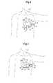
- FIG. 4is a schematic view of the S-ICD and lead of FIG. 1 subcutaneously implanted in the thorax of a patient;
- FIG. 5is a schematic view of the S-ICD and lead of FIG. 2 subcutaneously implanted in an alternate location within the thorax of a patient;
- FIG. 6is a schematic view of the S-ICD and lead of FIG. 3 subcutaneously implanted in the thorax of a patient;
- FIG. 7is a schematic view of the method of making a subcutaneous path from the preferred incision and housing implantation point to a termination point for locating a subcutaneous electrode of the present invention
- FIG. 9is a schematic view of an alternative S-ICD of the present invention illustrating a lead subcutaneously and serpiginously implanted in the thorax of a patient for use particularly in children;
- FIG. 10is a schematic view of an alternate embodiment of an S-ICD of the present invention.
- FIG. 11is a schematic view of the S-ICD of FIG. 10 subcutaneously implanted in the thorax of a patient;
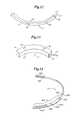
- FIG. 12is a schematic view of yet a further embodiment where the canister of the S-ICD of the present invention is shaped to be particularly useful in placing subcutaneously adjacent and parallel to a rib of a patient;
- FIG. 13is a schematic of a different embodiment where the canister of the S-ICD of the present invention is shaped to be particularly useful in placing subcutaneously adjacent and parallel to a rib of a patient;
- FIG. 14is a schematic view of a Unitary Subcutaneous ICD (US-ICD) of the present invention.
- FIG. 15is a schematic view of the US-ICD subcutaneously implanted in the thorax of a patient
- FIG. 16is a schematic view of the method of making a subcutaneous path from the preferred incision for implanting the US-ICD;
- FIG. 17is a schematic view of an introducer for performing the method of US-ICD implantation
- FIG. 18is an exploded schematic view of an alternate embodiment of the present invention with a plug-in portion that contains operational circuitry and means for generating cardioversion/defibrillation shock waves;
- FIG. 19is a graph that shows an example of a biphasic waveform for use in anti-bradycardia pacing in an embodiment of the present invention.
- the S-ICDconsists of an electrically active canister 11 and a subcutaneous electrode 13 attached to the canister.
- the canisterhas an electrically active surface 15 that is electrically insulated from the electrode connector block 17 and the canister housing 16 via insulating area 14 .
- the canistercan be similar to numerous electrically active canisters commercially available in that the canister will contain a battery supply, capacitor and operational circuitry. Alternatively, the canister can be thin and elongated to conform to the intercostal space.
- the circuitrywill be able to monitor cardiac rhythms for tachycardia and fibrillation, and if detected, will initiate charging the capacitor and then delivering cardioversion/defibrillation energy through the active surface of the housing and to the subcutaneous electrode. Examples of such circuitry are described in U.S. Pat. Nos. 4,693,253 and 5,105,810, the entire disclosures of which are herein incorporated by reference.
- the canister circuitrycan provide cardioversion/defibrillation energy in different types of waveforms.
- a 100 uF biphasic waveformis used of approximately 10-20 ms total duration and with the initial phase containing approximately 2 ⁇ 3 of the energy, however, any type of waveform can be utilized such as monophasic, biphasic, multiphasic or alternative waveforms as is known in the art.
- the circuitrycan also provide transthoracic cardiac pacing energy.
- the optional circuitrywill be able to monitor the heart for bradycardia and/or tachycardia rhythms. Once a bradycardia or tachycardia rhythm is detected, the circuitry can then deliver appropriate pacing energy at appropriate intervals through the active surface and the subcutaneous electrode.
- Pacing stimuliwill be biphasic in the preferred embodiment and similar in pulse amplitude to that used for conventional transthoracic pacing.
- This same circuitrycan also be used to deliver low amplitude shocks on the T-wave for induction of ventricular fibrillation for testing S-ICD performance in treating V-Fib as is described in U.S. Pat. No. 5,129,392, the entire disclosure of which is hereby incorporated by reference.
- the circuitrycan be provided with rapid induction of ventricular fibrillation or ventricular tachycardia using rapid ventricular pacing.
- Another optional way for inducing ventricular fibrillationwould be to provide a continuous low voltage, i.e., about 3 volts, across the heart during the entire cardiac cycle.
- the operational circuitrycan detect the presence of atrial fibrillation as described in Olson, W. et al. “Onset And Stability For Ventricular Tachyarrhythmia Detection in an Implantable Cardioverter and Defibrillator,” Computers in Cardiology (1986) pp. 167-170. Detection can be provided via R-R Cycle length instability detection algorithms. Once atrial fibrillation has been detected, the operational circuitry will then provide QRS synchronized atrial defibrillation/cardioversion using the same shock energy and waveshape characteristics used for ventricular defibrillation/cardioversion.
- the sensing circuitrywill utilize the electronic signals generated from the heart and will primarily detect QRS waves.
- the circuitrywill be programmed to detect only ventricular tachycardias or fibrillations.
- the detection circuitrywill utilize in its most direct form, a rate detection algorithm that triggers charging of the capacitor once the ventricular rate exceeds some predetermined level for a fixed period of time: for example, if the ventricular rate exceeds 240 bpm on average for more than 4 seconds. Once the capacitor is charged, a confirmatory rhythm check would ensure that the rate persists for at least another 1 second before discharge. Similarly, termination algorithms could be instituted that ensure that a rhythm less than 240 bpm persisting for at least 4 seconds before the capacitor charge is drained to an internal resistor.
- the sense circuitrycan check for the presence or the absence of respiration.
- the respiration ratecan be detected by monitoring the impedance across the thorax using subthreshold currents delivered across the active can and the high voltage subcutaneous lead electrode and monitoring the frequency in undulation in the waveform that results from the undulations of transthoracic impedance during the respiratory cycle. If there is no undulation, then the patent is not respiring and this lack of respiration can be used to confirm the QRS findings of cardiac arrest.
- the same techniquecan be used to provide information about the respiratory rate or estimate cardiac output as described in U.S. Pat. Nos. 6,095,987, 5,423,326, 4,450,527, the entire disclosures of which are incorporated herein by reference.
- the canister of the present inventioncan be made out of titanium alloy or other presently preferred electrically active canister designs. However, it is contemplated that a malleable canister that can conform to the curvature of the patient's chest will be preferred. In this way the patient can have a comfortable canister that conforms to the shape of the patient's rib cage. Examples of conforming canisters are provided in U.S. Pat. No. 5,645,586, the entire disclosure of which is herein incorporated by reference. Therefore, the canister can be made out of numerous materials such as medical grade plastics, metals, and alloys. In the preferred embodiment, the canister is smaller than 60 cc volume having a weight of less than 100 gms for long term wearability, especially in children.
- the canister and the lead of the S-ICDcan also use fractal or wrinkled surfaces to increase surface area to improve defibrillation capability. Because of the primary prevention role of the therapy and the likely need to reach energies over 40 Joules, a feature of the preferred embodiment is that the charge time for the therapy, intentionally e relatively long to allow capacitor charging within the limitations of device size. Examples of small ICD housings are disclosed in U.S. Pat. Nos. 5,597,956 and 5,405,363, the entire disclosures of which are herein incorporated by reference.
- the lead 21 for the subcutaneous electrodeis preferably composed of silicone or polyurethane insulation.
- the electrodeis connected to the canister at its proximal end via connection port 19 which is located on an electrically insulated area 17 of the canister.
- the electrode illustratedis a composite electrode with three different electrodes attached to the lead.
- an optional anchor segment 52is attached at the most distal end of the subcutaneous electrode for anchoring the electrode into soft tissue such that the electrode does not dislodge after implantation.
- the most distal electrode on the composite subcutaneous electrodeis a coil electrode 27 that is used for delivering the high voltage cardioversion/defibrillation energy across the heart.
- the coil cardioversion/defibrillation electrodeis about 5-10 cm in length.
- Proximal to the coil electrodeare two sense electrodes, a first sense electrode 25 is located proximally to the coil electrode and a second sense electrode 23 is located proximally to the first sense electrode.
- the sense electrodesare spaced far enough apart to be able to have good QRS detection. This spacing can range from 1 to 10 cm with 4 cm being presently preferred.
- the electrodesmay or may not be circumferential with the preferred embodiment.
- the sensing electrodesare electrically isolated from the cardioversion/defibrillation electrode via insulating areas 29 .
- Similar types of cardioversion/defibrillation electrodesare currently commercially available in a transvenous configuration.
- U.S. Pat. No. 5,534,022the entire disclosure of which is herein incorporated by reference, discloses a composite electrode with a coil cardioversion/defibrillation electrode and sense electrodes. Modifications to this arrangement are contemplated within the scope of the invention. One such modification is illustrated in FIG.
- FIG. 3illustrates yet a further embodiment where the two sensing electrodes are located at the distal end to the composite electrode with the coil electrode located proximally thereto.
- the sensing of QRS wavescan be carried out via sense electrodes on the canister housing or in combination with the cardioversion/defibrillation coil electrode and/or the subcutaneous lead sensing electrode(s).
- sensingcould be performed via the one coil electrode located on the subcutaneous electrode and the active surface on the canister housing.
- Another possibilitywould be to have only one sense electrode located on the subcutaneous electrode and the sensing would be performed by that one electrode and either the coil electrode on the subcutaneous electrode or by the active surface of the canister.
- the use of sensing electrodes on the canisterwould eliminate the need for sensing electrodes on the subcutaneous electrode.
- the subcutaneous electrodewould be provided with at least one sense electrode, the canister with at least one sense electrode, and if multiple sense electrodes are used on either the subcutaneous electrode and/or the canister, that the best QRS wave detection combination will be identified when the S-ICD is implanted and this combination can be selected, activating the best sensing arrangement from all the existing sensing possibilities.
- two sensing electrodes 26 and 28are located on the electrically active surface 15 with electrical insulator rings 30 placed between the sense electrodes and the active surface. These canister sense electrodes could be switched off and electrically insulated during and shortly after defibrillation/cardioversion shock delivery.
- the canister sense electrodesmay also be placed on the electrically inactive surface of the canister. In the embodiment of FIG. 2 , there are actually four sensing electrodes, two on the subcutaneous lead and two on the canister. In the preferred embodiment, the ability to change which electrodes are used for sensing would be a programmable feature of the S-ICD to adapt to changes in the patient physiology and size (in the case of children) over time.
- the programmingcould be done via the use of physical switches on the canister, or as presently preferred, via the use of a programming wand or via a wireless connection to program the circuitry within the canister.
- the canistercould be employed as either a cathode or an anode of the S-ICD cardioversion/defibrillation system. If the canister is the cathode, then the subcutaneous coil electrode would be the anode. Likewise, if the canister is the anode, then the subcutaneous electrode would be the cathode.
- the active canister housingwill provide energy and voltage intermediate to that available with ICDs and most AEDs.
- the typical maximum voltage necessary for ICDs using most biphasic waveformsis approximately 750 Volts with an associated maximum energy of approximately 40 Joules.
- the typical maximum voltage necessary for AEDsis approximately 2000-5000 Volts with an associated maximum energy of approximately 200-360 Joules depending upon the model and waveform used.
- the S-ICD of the present inventionuses maximum voltages in the range of about 700 to about 3150 Volts and is associated with energies of about 40 to about 210 Joules.
- the capacitance of the S-ICDcould range from about 50 to about 200 micro farads.
- the sense circuitry contained within the canisteris highly sensitive and specific for the presence or absence of life threatening ventricular arrhythmias.
- Features of the detection algorithmare programmable and the algorithm is focused on the detection of V-FIB and high rate V-TACH (>240 bpm).
- V-FIB and high rate V-TACH>240 bpm.
- the S-ICD of the present inventionmay rarely be used for an actual life threatening event, the simplicity of design and implementation allows it to be employed in large populations of patients at modest risk with modest cost by non-cardiac electrophysiologists. Consequently, the S-ICD of the present invention focuses mostly on the detection and therapy of the most malignant rhythm disorders.
- the upper rate rangeis programmable upward for use in children, known to have rapid supraventricular tachycardias and more rapid ventricular fibrillation. Energy levels also are programmable downward in order to allow treatment of neonates and infants.
- FIG. 4the optimal subcutaneous placement of the S-ICD of the present invention is illustrated.
- the actual location of the S-ICDis in a subcutaneous space that is developed during the implantation process.
- the heartis not exposed during this process and the heart is schematically illustrated in the Figures only for help in understanding where the canister and coil electrode are three dimensionally located in the left mid-clavicular line approximately at the level of the inframammary crease at approximately the 5th rib.
- the lead 21 of the subcutaneous electrodetraverses in a subcutaneous path around the thorax terminating with its distal electrode end at the posterior axillary line ideally just lateral to the left scapula. This way the canister and subcutaneous cardioversion/defibrillation electrode provide a reasonably good pathway for current delivery to the majority of the ventricular myocardium.
- FIG. 5illustrates a different placement of the present invention.
- the S-ICD canister with the active housingis located in the left posterior axillary line approximately lateral to the tip of the inferior portion of the scapula. This location is especially useful in children.
- the lead 21 of the subcutaneous electrodetraverses in a subcutaneous path around the thorax terminating with its distal electrode end at the anterior precordial region, ideally in the inframammary crease.
- FIG. 6illustrates the embodiment of FIG. 1 subcutaneously implanted in the thorax with the proximal sense electrodes 23 and 25 located at approximately the left axillary line with the cardioversion/defibrillation electrode just lateral to the tip of the inferior portion of the scapula.
- FIG. 7schematically illustrates the method for implanting the S-ICD of the present invention.
- An incision 31is made in the left anterior axillary line approximately at the level of the cardiac apex. This incision location is distinct from that chosen for S-ICD placement and is selected specifically to allow both canister location more medially in the left inframammary crease and lead positioning more posteriorly via the introducer set (described below) around to the left posterior axillary line lateral to the left scapula. That said, the incision can be anywhere on the thorax deemed reasonably by the implanting physician although in the preferred embodiment, the S-ICD of the present invention will be applied in this region.
- a subcutaneous pathway 33is then created medially to the inframammary crease for the canister and posteriorly to the left posterior axillary line lateral to the left scapula for the lead.
- the S-ICD canister 11is then placed subcutaneously at the location of the incision or medially at the subcutaneous region at the left inframammary crease.
- the subcutaneous electrode 13is placed with a specially designed curved introducer set 40 (see FIG. 8 ).
- the introducer setcomprises a curved trocar 42 and a stiff curved peel away sheath 44 .
- the peel away sheathis curved to allow for placement around the rib cage of the patient in the subcutaneous space created by the trocar.
- the sheathhas to be stiff enough to allow for the placement of the electrodes without the sheath collapsing or bending.
- the sheathis made out of a biocompatible plastic material and is perforated along its axial length to allow for it to split apart into two sections.
- the trocarhas a proximal handle 41 and a curved shaft 43 .
- the distal end 45 of the trocaris tapered to allow for dissection of a subcutaneous path 33 in the patient.
- the trocaris cannulated having a central Lumen 46 and terminating in an opening 48 at the distal end.
- Local anestheticsuch as lidocaine can be delivered, if necessary, through the lumen or through a curved and elongated needle designed to anesthetize the path to be used for trocar insertion should general anesthesia not be employed.
- the curved peel away sheath 44has a proximal pull tab 49 for breaking the sheath into two halves along its axial shaft 47 .
- the sheathis placed over a guidewire inserted through the trocar after the subcutaneous path has been created.
- the subcutaneous pathwayis then developed until it terminates subcutaneously at a location that, if a straight line were drawn from the canister location to the path termination point the line would intersect a substantial portion of the left ventricular mass of the patient.
- the guidewireis then removed leaving the peel away sheath.
- the subcutaneous lead systemis then inserted through the sheath until it is in the proper location. Once the subcutaneous lead system is in the proper location, the sheath is split in half using the pull tab 49 and removed. If more than one subcutaneous electrode is being used, a new curved peel away sheath can be used for each subcutaneous electrode.
- the S-ICDwill have prophylactic use in adults where chronic transvenous/epicardial ICD lead systems pose excessive risk or have already resulted in difficulty, such as sepsis or lead fractures. It is also contemplated that a major use of the S-ICD system of the present invention will be for prophylactic use in children who are at risk for having fatal arrhythmias, where chronic transvenous lead systems pose significant management problems. Additionally, with the use of standard transvenous ICDs in children, problems develop during patient growth in that the lead system does not accommodate the growth. FIG. 9 illustrates the placement of the S-ICD subcutaneous lead system such that the problem that growth presents to the lead system is overcome.
- the distal end of the subcutaneous electrodeis placed in the same location as described above providing a good location for the coil cardioversion/defibrillation electrode 27 and the sensing electrodes 23 and 25 .
- the insulated lead 21is no longer placed in a taut configuration. Instead, the lead is serpiginously placed with a specially designed introducer trocar and sheath such that it has numerous waves or bends. As the child grows, the waves or bends will straighten out lengthening the lead system while maintaining proper electrode placement.
- a lead system with a distal tine or screw electrode anchoring system 52can also be incorporated into the distal tip of the lead to facilitate lead stability (see FIG. 1 ).
- Other anchoring systemscan also be used such as hooks, sutures, or the like.
- FIGS. 10 and 11illustrate another embodiment of the present S-ICD invention.
- the additional subcutaneous electrode 13 ′is essentially identical to the previously described electrode.
- the cardioversion/defibrillation energyis delivered between the active surface of the canister and the two coil electrodes 27 and 27 ′.
- provided in the canisteris means for selecting the optimum sensing arrangement between the four sense electrodes 23 , 23 ′, 25 , and 25 ′.
- the two electrodesare subcutaneously placed on the same side of the heart. As illustrated in FIG. 6 , one subcutaneous electrode 13 is placed inferiorly and the other electrode 13 ′ is placed superiorly. It is also contemplated with this dual subcutaneous electrode system that the canister and one subcutaneous electrode are the same polarity and the other subcutaneous electrode is the opposite polarity.
- FIGS. 12 and 13further embodiments are illustrated where the canister 11 of the S-ICD of the present invention is shaped to be particularly useful in placing subcutaneously adjacent and parallel to a rib of a patient.
- the canisteris long, thin, and curved to conform to the shape of the patient's rib.
- the canisterhas a diameter ranging from about 0.5 cm to about 2 cm without 1 cm being presently preferred.
- the canistercould have a rectangular or square cross sectional area as illustrated in FIG. 13 without falling outside of the scope of the present invention.
- the length of the canistercan vary depending on the size of the patient's thorax.
- the canisteris about 5 cm to about 15 cm long with about 10 being presently preferred.
- the canisteris curved to conform to the curvature of the ribs of the thorax.
- the radius of the curvaturewill vary depending on the size of the patient, with smaller radiuses for smaller patients and larger radiuses for larger patients.
- the radius of the curvaturecan range from about 5 cm to about 35 cm depending on the size of the patient. Additionally, the radius of the curvature need not be uniform throughout the canister such that it can be shaped closer to the shape of the ribs.
- the canisterhas an active surface, 15 that is located on the interior (concave) portion of the curvature and an inactive surface 16 that is located on the exterior (convex) portion of the curvature.
- the leads of these embodimentswhich are not illustrated except for the attachment port 19 and the proximal end of the lead 21 , can be any of the leads previously described above, with the lead illustrated in FIG. 1 being presently preferred.
- the canistercan optionally have at least one sense electrode located on either the active surface of the inactive surface and the circuitry within the canister can be programmable as described above to allow for the selection of the best sense electrodes. It is presently preferred that the canister have two sense electrodes 26 and 28 located on the inactive surface of the canisters as illustrated, where the electrodes are spaced from about 1 to about 10 cm apart with a spacing of about 3 cm being presently preferred. However, the sense electrodes can be located on the active surface as described above.
- FIG. 12will be subcutaneously implanted adjacent and parallel to the left anterior 5th rib, either between the 4th and 5th ribs or between the 5th and 6th ribs. However other locations can be used.
- Another component of the S-ICD of the present inventionis a cutaneous test electrode system designed to simulate the subcutaneous high voltage shock electrode system as well as the QRS cardiac rhythm detection system.
- This test electrode systemis comprised of a cutaneous patch electrode of similar surface area and impedance to that of the S-ICD canister itself together with a cutaneous strip electrode comprising a defibrillation strip as well as two button electrodes for sensing of the QRS.
- Several cutaneous strip electrodesare available to allow for testing various bipole spacings to optimize signal detection comparable to the implantable system.
- FIGS. 14 to 18depict particular US-ICD embodiments of the present invention.
- the various sensing, shocking and pacing circuitry, described in detail above with respect to the S-ICD embodiments,may additionally be incorporated into the following US-ICD embodiments.
- particular aspects of any individual S-ICD embodiment discussed abovemay be incorporated, in whole or in part, into the US-ICD embodiments depicted in the following Figures.
- the US-ICDconsists of a curved housing 1211 with a first and second end.
- the first end 1413is thicker than the second end 1215 .
- This thicker areahouses a battery supply, capacitor and operational circuitry for the US-ICD.
- the circuitrywill be able to monitor cardiac rhythms for tachycardia and fibrillation, and if detected, will initiate charging the capacitor and then delivering cardioversion/defibrillation energy through the two cardioversion/defibrillating electrodes 1417 and 1219 located on the outer surface of the two ends of the housing.
- the circuitrycan provide cardioversion/defibrillation energy in different types of waveforms.
- a 100 uF biphasic waveformis used of approximately 10-20 ms total duration and with the initial phase containing approximately 2 ⁇ 3 of the energy, however, any type of waveform can be utilized such as monophasic, biphasic, multiphasic or alternative waveforms as is known in the art.
- the housing of the present inventioncan be made out of titanium alloy or other presently preferred ICD designs. It is contemplated that the housing is also made out of biocompatible plastic materials that electronically insulate the electrodes from each other. However, it is contemplated that a malleable canister that can conform to the curvature of the patient's chest will be preferred. In this way the patient can have a comfortable canister that conforms to the unique shape of the patient's rib cage. Examples of conforming ICD housings are provided in U.S. Pat. No. 5,645,586, the entire disclosure of which is herein incorporated by reference. In the preferred embodiment, the housing is curved in the shape of a 5th rib of a person.
- the housingwill come in different incremental sizes to allow a good match between the size of the rib cage and the size of the US-ICD.
- the length of the US-ICDwill range from about 15 to about 50 cm. Because of the primary preventative role of the therapy and the need to reach energies over 40 Joules, a feature of the preferred embodiment is that the charge time for the therapy, intentionally be relatively long to allow capacitor charging within the limitations of device size.
- the thick end of the housingis currently needed to allow for the placement of the battery supply, operational circuitry, and capacitors. It is contemplated that the thick end will be about 0.5 cm to about 2 cm wide with about 1 cm being presently preferred. As microtechnology advances, the thickness of the housing will become smaller.
- the electrodesmay or may not be circumferential with the preferred embodiment. Having the electrodes non-circumferential and positioned outward, toward the skin surface, is a means to minimize muscle artifact and enhance QRS signal quality.
- the sensing electrodesare electrically isolated from the cardioversion/defibrillation electrode via insulating areas 1423 .
- Analogous types of cardioversion/defibrillation electrodesare currently commercially available in a transvenous configuration.
- U.S. Pat. No. 5,534,022the entire disclosure of which is herein incorporated by reference, discloses a composite electrode with a coil cardioversion/defibrillation electrode and sense electrodes. Modifications to this arrangement are contemplated within the scope of the invention.
- One such modificationis to have the sense electrodes at the two ends of the housing and have the cardioversion/defibrillation electrodes located in between the sense electrodes.
- Another modificationis to have three or more sense electrodes spaced throughout the housing and allow for the selection of the two best sensing electrodes. If three or more sensing electrodes are used, then the ability to change which electrodes are used for sensing would be a programmable feature of the US-ICD to adapt to changes in the patient physiology and size over time.
- the programmingcould be done via the use of physical switches on the canister, or as presently preferred, via the use of a programming wand or via a wireless connection to program the circuitry within the canister.
- FIG. 16schematically illustrates the method for implanting the US-ICD of the present invention.
- An incision 1631is made in the left anterior axillary line approximately at the level of the cardiac apex.
- a subcutaneous pathwayis then created that extends posteriorly to allow placement of the US-ICD.
- the incisioncan be anywhere on the thorax deemed reasonable by the implanting physician although in the preferred embodiment, the US-ICD of the present invention will be applied in this region.
- the subcutaneous pathwayis created medially to the inframammary crease and extends posteriorly to the left posterior axillary line.
- the pathwayis developed with a specially designed curved introducer 1742 (see FIG. 17 ).
- the trocarhas a proximal handle 1641 and a curved shaft 1643 .
- the distal end 1745 of the trocaris tapered to allow for dissection of a subcutaneous path in the patient.
- the trocaris cannulated having a central lumen 1746 and terminating in an opening 1748 at the distal end.
- Local anestheticsuch as lidocaine can be delivered, if necessary, through the lumen or through a curved and elongated needle designed to anesthetize the path to be used for trocar insertion should general anesthesia not be employed.
- the US-ICDs of the present inventionvary in length and curvature.
- the US-ICDsare provided in incremental sizes for subcutaneous implantation in different sized patients.
- FIG. 18a different embodiment is schematically illustrated in exploded view which provides different sized US-ICDs that are easier to manufacture.
- the different sized US-ICDswill all have the same sized and shaped thick end 1413 .
- the thick endis hollow inside allowing for the insertion of a core operational member 1853 .
- the core membercomprises a housing 1857 which contains the battery supply, capacitor and operational circuitry for the US-ICD.
- the proximal end of the core memberhas a plurality of electronic plug connectors.
- Plug connectors 1861 and 1863are electronically connected to the sense electrodes via pressure fit connectors (not illustrated) inside the thick end which are standard in the art.
- Plug connectors 1865 and 1867are also electronically connected to the cardioverter/defibrillator electrodes via pressure fit connectors inside the thick end.
- the distal end of the core membercomprises an end cap 1855 , and a ribbed fitting 1859 which creates a water-tight seal when the core member is inserted into opening 1851 of the thick end of the US-ICD.
- the core member of the different sized and shaped US-ICDwill all be the same size and shape. That way, during an implantation procedure, multiple sized US-ICDs can be available for implantation, each one without a core member. Once the implantation procedure is being performed, then the correct sized US-ICD can be selected and the core member can be inserted into the US-ICD and then programmed as described above. Another advantage of this configuration is when the battery within the core member needs replacing it can be done without removing the entire US-ICD.
- FIG. 19is a graph that shows an embodiment of the example of a biphasic waveform for use in anti-bradycardia pacing applications in subcutaneous implantable cardioverter-defibrillators (“S-ICD”) in an embodiment of the present invention. As shown in FIG. 19 , the biphasic waveform is plotted as a function of time versus instantaneous voltage.
- S-ICDsubcutaneous implantable cardioverter-defibrillators
- the biphasic waveform 1902comprises a positive portion 1904 , a negative portion 1906 and a transition portion 1908 .
- the positive portion 1904 of the biphasic waveform 1902comprises an initial positive voltage 1910 , a positive decay voltage 1912 and a final positive voltage 1914 .
- the negative portion 1906 of the biphasic waveform 1902comprises an initial negative voltage 1916 , a negative decay voltage 1918 and a final negative voltage 1920 .
- the polarities of the biphasic waveform 1902can be reversed such that the negative portion 1906 precedes the positive portion 1904 in time.
- the biphasic waveform 1902is initially at zero voltage. Upon commencement of the anti-bradycardia pacing, a voltage of positive polarity is provided and the biphasic waveform 1902 rises to the initial positive voltage 1910 . Next, the voltage of the biphasic waveform 1902 decays along the positive decay voltage 1912 until reaching a voltage level at the final positive voltage 1914 . At this point, the positive portion 1904 of the biphasic waveform 1902 is truncated and a negative voltage is provided. The biphasic waveform 1902 then undergoes a relatively short transition portion 1908 where the voltage is approximately zero.
- the biphasic waveform 1902is increased (in absolute value) in the opposite (negative) polarity to the initial negative voltage 1916 .
- the voltage of the biphasic waveform 1902decays along the negative decay voltage 1918 until reaching a voltage level at the final negative voltage 1914 .
- the biphasic waveform 1902returns to zero.
- the total amount of time that the biphasic waveform 1902 comprisesis known as the “pulse width.”
- the pulse width of the biphasic waveformcan range from approximately 2 milliseconds to approximately 40 milliseconds.
- the total amount of energy deliveredis a function of the pulse width and the average (absolute) value of the voltage.
- the ratio of the final positive voltage 1914 (or final negative voltage 1920 ) to the initial positive voltage 1910 (initial negative voltage 1916 )is known as the “tilt” of the waveform.
- the tilt of the positive portion 1904 of the biphasic waveform 1902is equal to the negative portion 1906 . However, depending upon the specific application, these two tilts may be different from each other.
- the amplitude of the initial positive voltage 1910can range from approximately 5 to approximately 500 volts. In one example, the amplitude of the initial positive voltage 1910 is approximately 20 volts.
- the tilt of the positive decay voltage 1912is approximately 50%. Typically, the tilt of the positive decay voltage 1912 can range from approximately 10% to approximately 90% although the waveform tilt can be considerably higher or lower, depending on variables such as capacitance, tissue resistance and type of electrode system used. Assuming a 50% tilt for this example, the amplitude of the trailing edge of the final positive voltage 1914 is approximately 10 volts, but can vary between approximately 2 volts to approximately 300 volts.
- the amplitude of the initial negative voltage 1916can range from approximately ⁇ 5 to approximately ⁇ 500 volts. In one example, the amplitude of the initial negative voltage 1916 is approximately ⁇ 20 volts.
- the tilt of the negative decay voltage 1918is approximately 50%. Typically, the tilt of the negative decay voltage 1918 can range from approximately 10% to approximately 90%. However, like the initial positive phase described above, the tilt and amplitude of an effective pacing pulse may vary considerably. Assuming a 50% tilt for this example, the amplitude of the final negative voltage is approximately ⁇ 10 volts, but can vary between approximately ⁇ 2 volts to approximately ⁇ 300 volts.
- the pulse width of the biphasic waveform 1902can range from approximately 2 milliseconds to approximately 40 milliseconds.
- the implantable cardioverter-defibrillatoremploys anti-bradycardia pacing at rates of approximately 40 to approximately 120 stimuli/minute for severe bradycardia episodes although programming of higher pacing rates up to 120 stimuli/minute is also possible.
- one embodimentprovides anti-bradycardia pacing only for bradycardia or post-shock bradycardia.
- a hysteresis detection triggercan be employed at lower rates, typically in the range of approximately 20 to approximately 40 stimuli/minute.
- a default settingmay be set at approximately 20 stimuli/minute (i.e., the equivalent of a 3 second pause), and the invention providing VVI pacing at a rate of approximately 50 stimuli/minute only when such a pause occurs.
- the inventioncan provide physiologic pacing in a VVIR mode of operation in response to a certain activity, respiration, pressure or oxygenation sensor.
Landscapes
- Health & Medical Sciences (AREA)
- Cardiology (AREA)
- Radiology & Medical Imaging (AREA)
- Engineering & Computer Science (AREA)
- Biomedical Technology (AREA)
- Nuclear Medicine, Radiotherapy & Molecular Imaging (AREA)
- Life Sciences & Earth Sciences (AREA)
- Animal Behavior & Ethology (AREA)
- General Health & Medical Sciences (AREA)
- Public Health (AREA)
- Veterinary Medicine (AREA)
- Heart & Thoracic Surgery (AREA)
- Electrotherapy Devices (AREA)
Abstract
Description
Claims (18)
Priority Applications (1)
| Application Number | Priority Date | Filing Date | Title |
|---|---|---|---|
| US11/553,785US7751885B2 (en) | 2000-09-18 | 2006-10-27 | Bradycardia pacing in a subcutaneous device |
Applications Claiming Priority (4)
| Application Number | Priority Date | Filing Date | Title |
|---|---|---|---|
| US09/663,606US6647292B1 (en) | 2000-09-18 | 2000-09-18 | Unitary subcutaneous only implantable cardioverter-defibrillator and optional pacer |
| US09/663,607US6721597B1 (en) | 2000-09-18 | 2000-09-18 | Subcutaneous only implantable cardioverter defibrillator and optional pacer |
| US09/940,378US7146212B2 (en) | 2000-09-18 | 2001-08-27 | Anti-bradycardia pacing for a subcutaneous implantable cardioverter-defibrillator |
| US11/553,785US7751885B2 (en) | 2000-09-18 | 2006-10-27 | Bradycardia pacing in a subcutaneous device |
Related Parent Applications (2)
| Application Number | Title | Priority Date | Filing Date |
|---|---|---|---|
| US09/940,378Continuation-In-PartUS7146212B2 (en) | 2000-09-18 | 2001-08-27 | Anti-bradycardia pacing for a subcutaneous implantable cardioverter-defibrillator |
| US09/940,378ContinuationUS7146212B2 (en) | 2000-09-18 | 2001-08-27 | Anti-bradycardia pacing for a subcutaneous implantable cardioverter-defibrillator |
Publications (2)
| Publication Number | Publication Date |
|---|---|
| US20070049979A1 US20070049979A1 (en) | 2007-03-01 |
| US7751885B2true US7751885B2 (en) | 2010-07-06 |
Family
ID=46326416
Family Applications (1)
| Application Number | Title | Priority Date | Filing Date |
|---|---|---|---|
| US11/553,785Expired - Fee RelatedUS7751885B2 (en) | 2000-09-18 | 2006-10-27 | Bradycardia pacing in a subcutaneous device |
Country Status (1)
| Country | Link |
|---|---|
| US (1) | US7751885B2 (en) |
Cited By (23)
| Publication number | Priority date | Publication date | Assignee | Title |
|---|---|---|---|---|
| US20100174341A1 (en)* | 2008-12-31 | 2010-07-08 | Bolea Stephen L | Obstructive Sleep Apnea Treatment Devices, Systems and Methods |
| US8311645B2 (en) | 2006-10-13 | 2012-11-13 | Apnex Medical, Inc. | Obstructive sleep apnea treatment devices, systems and methods |
| US8386046B2 (en) | 2011-01-28 | 2013-02-26 | Apnex Medical, Inc. | Screening devices and methods for obstructive sleep apnea therapy |
| US8706217B2 (en) | 2000-09-18 | 2014-04-22 | Cameron Health | Cardioverter-defibrillator having a focused shocking area and orientation thereof |
| US8718760B2 (en) | 2000-09-18 | 2014-05-06 | Cameron Health Inc. | Subcutaneous implantable cardioverter-defibrillator placement methods |
| US8838234B2 (en) | 2000-09-18 | 2014-09-16 | Cameron Health, Inc. | Methods for implanting a subcutaneous defibrillator |
| US8855771B2 (en) | 2011-01-28 | 2014-10-07 | Cyberonics, Inc. | Screening devices and methods for obstructive sleep apnea therapy |
| US9186511B2 (en) | 2006-10-13 | 2015-11-17 | Cyberonics, Inc. | Obstructive sleep apnea treatment devices, systems and methods |
| US9205262B2 (en) | 2011-05-12 | 2015-12-08 | Cyberonics, Inc. | Devices and methods for sleep apnea treatment |
| US20170157399A1 (en)* | 2015-12-03 | 2017-06-08 | Medtronic, Inc. | Extra-cardiovascular cardiac pacing system for delivering composite pacing pulses |
| US10046168B2 (en) | 2015-12-03 | 2018-08-14 | Medtronic, Inc. | Tachyarrhythmia induction by an extra-cardiovascular implantable cardioverter defibrillator |
| US10080905B2 (en) | 2015-12-03 | 2018-09-25 | Medtronic, Inc. | Extra-cardiovascular pacing by an implantable cardioverter defibrillator |
| US10080891B2 (en) | 2015-12-03 | 2018-09-25 | Medtronic, Inc. | Extra-cardiovascular cardiac pacing system |
| US10154794B2 (en) | 2014-04-25 | 2018-12-18 | Medtronic, Inc. | Implantable cardioverter-defibrillator (ICD) tachyarrhythmia detection modifications responsive to detected pacing |
| US10226197B2 (en) | 2014-04-25 | 2019-03-12 | Medtronic, Inc. | Pace pulse detector for an implantable medical device |
| US10448855B2 (en) | 2014-04-25 | 2019-10-22 | Medtronic, Inc. | Implantable medical device (IMD) sensing modifications responsive to detected pacing pulses |
| US10743960B2 (en) | 2014-09-04 | 2020-08-18 | AtaCor Medical, Inc. | Cardiac arrhythmia treatment devices and delivery |
| US10905885B2 (en) | 2014-09-04 | 2021-02-02 | AtaCor Medical, Inc. | Cardiac defibrillation |
| US11026718B2 (en) | 2014-09-04 | 2021-06-08 | AtaCor Medical, Inc. | Delivery system for cardiac pacing |
| US11097109B2 (en) | 2014-11-24 | 2021-08-24 | AtaCor Medical, Inc. | Cardiac pacing sensing and control |
| US11383083B2 (en) | 2014-02-11 | 2022-07-12 | Livanova Usa, Inc. | Systems and methods of detecting and treating obstructive sleep apnea |
| US11666771B2 (en) | 2020-05-29 | 2023-06-06 | AtaCor Medical, Inc. | Implantable electrical leads and associated delivery systems |
| US11672975B2 (en) | 2019-05-29 | 2023-06-13 | AtaCor Medical, Inc. | Implantable electrical leads and associated delivery systems |
Families Citing this family (2)
| Publication number | Priority date | Publication date | Assignee | Title |
|---|---|---|---|---|
| US7039465B2 (en)* | 2000-09-18 | 2006-05-02 | Cameron Health, Inc. | Ceramics and/or other material insulated shell for active and non-active S-ICD can |
| US8838236B2 (en) | 2012-09-21 | 2014-09-16 | Physio-Control. Inc. | Wearable cardiac defibrillator system with anti-bradyarrhythmia pacing and methods |
Citations (148)
| Publication number | Priority date | Publication date | Assignee | Title |
|---|---|---|---|---|
| US3653387A (en) | 1970-05-08 | 1972-04-04 | Cardiac Electronics Inc | Protector circuit for cardiac apparatus |
| US3710374A (en) | 1970-03-16 | 1973-01-09 | Wester Instr Inc | Dual-slope and analog-to-digital converter wherein two analog input signals are selectively integrated with respect to time |
| US3911925A (en) | 1974-05-23 | 1975-10-14 | Jr Joe B Tillery | Ear trimming forceps |
| US4157720A (en) | 1977-09-16 | 1979-06-12 | Greatbatch W | Cardiac pacemaker |
| US4191942A (en) | 1978-06-08 | 1980-03-04 | National Semiconductor Corporation | Single slope A/D converter with sample and hold |
| US4223678A (en) | 1978-05-03 | 1980-09-23 | Mieczyslaw Mirowski | Arrhythmia recorder for use with an implantable defibrillator |
| US4248237A (en) | 1978-03-07 | 1981-02-03 | Needle Industries Limited | Cardiac pacemakers |
| US4291707A (en) | 1979-04-30 | 1981-09-29 | Mieczyslaw Mirowski | Implantable cardiac defibrillating electrode |
| US4314095A (en) | 1979-04-30 | 1982-02-02 | Mieczyslaw Mirowski | Device and method for making electrical contact |
| US4349030A (en) | 1980-07-10 | 1982-09-14 | Ross H. Zoll | External noninvasive electric cardiac stimulation |
| US4402322A (en) | 1981-03-25 | 1983-09-06 | Medtronic, Inc. | Pacer output circuit |
| US4406286A (en) | 1981-04-09 | 1983-09-27 | Medtronic, Inc. | Fast recharge output circuit |
| US4407288A (en) | 1981-02-18 | 1983-10-04 | Mieczyslaw Mirowski | Implantable heart stimulator and stimulation method |
| US4412541A (en) | 1981-04-10 | 1983-11-01 | Max Schaldach | Cardiac pacemaker |
| EP0095727A1 (en) | 1982-06-01 | 1983-12-07 | Purdue Research Foundation | Method and apparatus for inserting a defibrillator electrode and defibrillator electrode |
| US4424818A (en) | 1982-02-18 | 1984-01-10 | Medtronic, Inc. | Electrical lead and insertion tool |
| US4543956A (en) | 1984-05-24 | 1985-10-01 | Cordis Corporation | Biphasic cardiac pacer |
| US4602637A (en) | 1983-01-11 | 1986-07-29 | Siemens Aktiengesellschaft | Heart pacemaker system |
| US4765341A (en) | 1981-06-22 | 1988-08-23 | Mieczyslaw Mirowski | Cardiac electrode with attachment fin |
| US4800883A (en) | 1986-04-02 | 1989-01-31 | Intermedics, Inc. | Apparatus for generating multiphasic defibrillation pulse waveform |
| US4830006A (en)* | 1986-06-17 | 1989-05-16 | Intermedics, Inc. | Implantable cardiac stimulator for detection and treatment of ventricular arrhythmias |
| US4830005A (en) | 1987-07-23 | 1989-05-16 | Siemens-Pacesetter, Inc. | Disposable in-package load test element for pacemakers |
| EP0316616A2 (en) | 1987-11-19 | 1989-05-24 | Siemens Aktiengesellschaft | Analog-digital converter |
| EP0347353A1 (en) | 1988-06-15 | 1989-12-20 | ATESYS, société anonyme | High performance defibrillator with several electrodes outside the heart |
| US4940054A (en) | 1988-04-29 | 1990-07-10 | Telectronics N.V. | Apparatus and method for controlling multiple sensitivities in arrhythmia control system including post therapy packing delay |
| US5109842A (en) | 1990-09-24 | 1992-05-05 | Siemens Pacesetter, Inc. | Implantable tachyarrhythmia control system having a patch electrode with an integrated cardiac activity system |
| US5129392A (en) | 1990-12-20 | 1992-07-14 | Medtronic, Inc. | Apparatus for automatically inducing fibrillation |
| US5133353A (en) | 1990-04-25 | 1992-07-28 | Cardiac Pacemakers, Inc. | Implantable intravenous cardiac stimulation system with pulse generator housing serving as optional additional electrode |
| US5144946A (en) | 1991-08-05 | 1992-09-08 | Siemens Pacesetter, Inc. | Combined pacemaker substrate and electrical interconnect and method of assembly |
| US5170784A (en) | 1990-11-27 | 1992-12-15 | Ceon Ramon | Leadless magnetic cardiac pacemaker |
| EP0518599A2 (en) | 1991-06-14 | 1992-12-16 | Telectronics N.V. | Implantable pacemaker/cardioverter/defibrillator device and method incorporating multiple bradycardia support pacing rates |
| US5184616A (en) | 1991-10-21 | 1993-02-09 | Telectronics Pacing Systems, Inc. | Apparatus and method for generation of varying waveforms in arrhythmia control system |
| US5191901A (en) | 1991-08-29 | 1993-03-09 | Mieczyslaw Mirowski | Controlled discharge defibrillation electrode |
| US5193535A (en)* | 1991-08-27 | 1993-03-16 | Medtronic, Inc. | Method and apparatus for discrimination of ventricular tachycardia from ventricular fibrillation and for treatment thereof |
| US5203348A (en) | 1990-06-06 | 1993-04-20 | Cardiac Pacemakers, Inc. | Subcutaneous defibrillation electrodes |
| US5230337A (en) | 1990-06-06 | 1993-07-27 | Cardiac Pacemakers, Inc. | Process for implanting subcutaneous defibrillation electrodes |
| US5243978A (en) | 1991-10-07 | 1993-09-14 | Medtronic, Inc. | Method and apparatus for wide area antitachycardia pacing |
| US5243977A (en) | 1991-06-26 | 1993-09-14 | Trabucco Hector O | Pacemaker |
| WO1993019809A1 (en) | 1992-04-06 | 1993-10-14 | Angemed, Inc. | System for treatment of ventricular tachycardia using a far-field pulse series |
| US5255692A (en) | 1992-09-04 | 1993-10-26 | Siemens Aktiengesellschaft | Subcostal patch electrode |
| US5261401A (en) | 1988-11-04 | 1993-11-16 | James Baker | Ambulatory cardiac diagnostic units having means for inhibiting pacemaker response |
| US5261400A (en) | 1992-02-12 | 1993-11-16 | Medtronic, Inc. | Defibrillator employing transvenous and subcutaneous electrodes and method of use |
| US5300106A (en) | 1991-06-07 | 1994-04-05 | Cardiac Pacemakers, Inc. | Insertion and tunneling tool for a subcutaneous wire patch electrode |
| US5331966A (en) | 1991-04-05 | 1994-07-26 | Medtronic, Inc. | Subcutaneous multi-electrode sensing system, method and pacer |
| US5366496A (en) | 1993-04-01 | 1994-11-22 | Cardiac Pacemakers, Inc. | Subcutaneous shunted coil electrode |
| US5376103A (en) | 1992-03-19 | 1994-12-27 | Angeion Corporation | Electrode system for implantable defibrillator |
| US5376104A (en) | 1992-02-07 | 1994-12-27 | Nihon Kohden Corporation | Defibrillator with electrocardiogram monitor |
| US5391200A (en) | 1992-09-30 | 1995-02-21 | Cardiac Pacemakers, Inc. | Defibrillation patch electrode having conductor-free resilient zone for minimally invasive deployment |
| EP0641573A2 (en) | 1993-08-31 | 1995-03-08 | Ventritex, Inc. | Method and apparatus for phase related cardiac defibrillation |
| US5411547A (en) | 1993-08-09 | 1995-05-02 | Pacesetter, Inc. | Implantable cardioversion-defibrillation patch electrodes having means for passive multiplexing of discharge pulses |
| US5411539A (en) | 1993-08-31 | 1995-05-02 | Medtronic, Inc. | Active can emulator and method of use |
| US5413591A (en) | 1992-02-26 | 1995-05-09 | Angeion Corporation | Current truncated waveform defibrillator |
| US5441518A (en) | 1993-07-22 | 1995-08-15 | Angeion Corporation | Implantable cardioverter defibrillator system having independently controllable electrode discharge pathway |
| EP0677301A1 (en) | 1994-04-14 | 1995-10-18 | Pacesetter AB | Electrode apparatus with a variable distance between the electrodes |
| US5489293A (en)* | 1993-08-31 | 1996-02-06 | Ventritex, Inc. | Method and apparatus for treating cardiac tachyarrhythmia |
| US5509928A (en) | 1995-03-02 | 1996-04-23 | Pacesetter, Inc. | Internally supported self-sealing septum |
| US5509923A (en) | 1989-08-16 | 1996-04-23 | Raychem Corporation | Device for dissecting, grasping, or cutting an object |
| US5531766A (en) | 1995-01-23 | 1996-07-02 | Angeion Corporation | Implantable cardioverter defibrillator pulse generator kite-tail electrode system |
| US5531765A (en) | 1990-12-18 | 1996-07-02 | Ventritex, Inc. | Method and apparatus for producing configurable biphasic defibrillation waveforms |
| US5534019A (en) | 1994-12-09 | 1996-07-09 | Ventritex, Inc. | Cardiac defibrillator with case that can be electrically active or inactive |
| US5601607A (en) | 1992-03-19 | 1997-02-11 | Angeion Corporation | Implantable cardioverter defibrillator housing plated electrode |
| US5618287A (en) | 1994-01-28 | 1997-04-08 | Thomas J. Fogarty | Methods of surgically implanting a defibrillator electrode within a patient |
| US5620477A (en) | 1994-03-31 | 1997-04-15 | Ventritex, Inc. | Pulse generator with case that can be active or inactive |
| US5643328A (en) | 1996-07-19 | 1997-07-01 | Sulzer Intermedics Inc. | Implantable cardiac stimulation device with warning system having elongated stimulation electrode |
| US5645586A (en) | 1994-07-08 | 1997-07-08 | Ventritex, Inc. | Conforming implantable defibrillator |
| US5658317A (en) | 1995-08-14 | 1997-08-19 | Cardiac Pacemakers, Inc. | Threshold templating for digital AGC |
| WO1997029802A2 (en) | 1996-02-20 | 1997-08-21 | Advanced Bionics Corporation | Improved implantable microstimulator and systems employing the same |
| EP0536873B1 (en) | 1991-10-07 | 1997-09-17 | Telectronics N.V. | Apparatus for arrhythmia induction in arrhythmia control system |
| US5674260A (en) | 1996-02-23 | 1997-10-07 | Pacesetter, Inc. | Apparatus and method for mounting an activity sensor or other component within a pacemaker using a contoured hybrid lid |
| US5690683A (en) | 1995-06-19 | 1997-11-25 | Cardiac Pacemakers, Inc. | After potential removal in cardiac rhythm management device |
| US5697953A (en) | 1993-03-13 | 1997-12-16 | Angeion Corporation | Implantable cardioverter defibrillator having a smaller displacement volume |
| US5713926A (en) | 1990-04-25 | 1998-02-03 | Cardiac Pacemakers, Inc. | Implantable intravenous cardiac stimulation system with pulse generator housing serving as optional additional electrode |
| DE29801807U1 (en) | 1997-02-04 | 1998-06-04 | Mathar, Ralph, Humble | Device for use in surgical interventions, in particular in bypass operations |
| WO1998025349A1 (en) | 1996-12-03 | 1998-06-11 | Microchip Technology Incorporated | Slope analog-to-digital converter with ramp initiated prior to counter |
| US5766226A (en) | 1996-12-09 | 1998-06-16 | Angeion Corporation | Switched discharge pathways for ICD having multiple output capacitors |
| US5776169A (en) | 1997-04-28 | 1998-07-07 | Sulzer Intermedics Inc. | Implantable cardiac stimulator for minimally invasive implantation |
| US5800470A (en)* | 1994-01-07 | 1998-09-01 | Medtronic, Inc. | Respiratory muscle electromyographic rate responsive pacemaker |
| US5814090A (en) | 1995-06-07 | 1998-09-29 | Angeion Corporation | Implantable medical device having heat-shrink conforming shield |
| US5836976A (en) | 1997-04-30 | 1998-11-17 | Medtronic, Inc. | Cardioversion energy reduction system |
| WO1999003534A1 (en) | 1997-07-17 | 1999-01-28 | Cpr Medical, Inc. | Defibrillator/pacemaker |
| US5871508A (en)* | 1997-08-06 | 1999-02-16 | Medtronic, Inc. | Apparatus for cardiac pacing in transplant |
| US5895414A (en) | 1996-04-19 | 1999-04-20 | Sanchez-Zambrano; Sergio | Pacemaker housing |
| EP0917887A1 (en) | 1997-11-24 | 1999-05-26 | Pacesetter AB | A cardiac event detecting system for a heart stimulator |
| EP0923130A1 (en) | 1997-12-12 | 1999-06-16 | ELA MEDICAL (Société anonyme) | Electronic circuit, in particular for implantable active medical device, like a heart stimulator or defibrillator, and its manufacturing method |
| US5919222A (en) | 1998-01-06 | 1999-07-06 | Medtronic Inc. | Adjustable medical electrode lead |
| US5919211A (en) | 1996-06-27 | 1999-07-06 | Adams; Theodore P. | ICD power source using multiple single use batteries |
| US5925069A (en) | 1997-11-07 | 1999-07-20 | Sulzer Intermedics Inc. | Method for preparing a high definition window in a conformally coated medical device |
| WO1999037362A1 (en) | 1998-01-27 | 1999-07-29 | Vitatron Medical, B.V. | System for inducing tachycardia utilizing near field t-wave sensing |
| US5935154A (en) | 1997-01-24 | 1999-08-10 | Cardiac Pacemakers, Inc. | Implantable tissue stimulator incorporating deposited multilayer capacitor |
| US5941904A (en) | 1997-09-12 | 1999-08-24 | Sulzer Intermedics Inc. | Electromagnetic acceleration transducer for implantable medical device |
| US5964787A (en) | 1998-04-17 | 1999-10-12 | Vitatron Medical B.V. | Stimulus system with controllable switched capacitor output stage |
| WO1999053991A1 (en) | 1998-04-23 | 1999-10-28 | Alza Corporation | Trocar for inserting implants |
| US6014586A (en) | 1995-11-20 | 2000-01-11 | Pacesetter, Inc. | Vertically integrated semiconductor package for an implantable medical device |
| US6026325A (en) | 1998-06-18 | 2000-02-15 | Pacesetter, Inc. | Implantable medical device having an improved packaging system and method for making electrical connections |
| US6058328A (en) | 1996-08-06 | 2000-05-02 | Pacesetter, Inc. | Implantable stimulation device having means for operating in a preemptive pacing mode to prevent tachyarrhythmias and method thereof |
| EP1000634A1 (en) | 1998-11-10 | 2000-05-17 | Sulzer Osypka GmbH | Stimulation electrode for both defibrillation and pacing |
| WO2000041766A1 (en) | 1999-01-14 | 2000-07-20 | The Mower Family Chf Treatment Irrevocable Trust | Antitachycardial pacing |
| US6093173A (en) | 1998-09-09 | 2000-07-25 | Embol-X, Inc. | Introducer/dilator with balloon protection and methods of use |
| US6095987A (en) | 1996-04-17 | 2000-08-01 | Imagyn Medical Techonologies California, Inc. | Apparatus and methods of bioelectrical impedance analysis of blood flow |
| WO2000050120A1 (en) | 1999-02-25 | 2000-08-31 | St. Jude Medical Ab | Implantable tissue stimulating device |
| US6128531A (en) | 1998-04-01 | 2000-10-03 | Pacesetter, Inc. | Delivery of ICD shock capacitor energy via a controlled current source |
| USH1905H (en) | 1997-03-21 | 2000-10-03 | Medtronic, Inc. | Mechanism for adjusting the exposed surface area and position of an electrode along a lead body |
| US6144866A (en) | 1998-10-30 | 2000-11-07 | Medtronic, Inc. | Multiple sensor assembly for medical electric lead |
| US6148230A (en) | 1998-01-30 | 2000-11-14 | Uab Research Foundation | Method for the monitoring and treatment of spontaneous cardiac arrhythmias |
| US6185450B1 (en) | 1998-01-26 | 2001-02-06 | Physio-Control Manufacturing Corporation | Digital sliding pole fast-restore for an electrocardiograph display |
| WO2001043649A1 (en) | 1999-12-17 | 2001-06-21 | Fogarty Thomas J | Method and device for use in minimally invasive approximation of muscle and other tissue |
| WO2001056166A2 (en) | 2000-01-28 | 2001-08-02 | Infineon Technologies Ag | Method and analog-to-digital converter for converting an analog voltage into an arithmetical value |
| US20010027330A1 (en) | 1998-10-13 | 2001-10-04 | Physio-Control Manufacturing Corporation | Circuit for performing external pacing and biphasic defibrillation |
| WO2002024275A2 (en) | 2000-09-18 | 2002-03-28 | Cameron Health, Inc. | Unitary subcutaneous only implantable cardioverter-debribillator and optional pacer |
| US6411844B1 (en) | 1999-10-19 | 2002-06-25 | Pacesetter, Inc. | Fast recovery sensor amplifier circuit for implantable medical device |
| WO2002068046A1 (en) | 2000-11-03 | 2002-09-06 | Medtronic, Inc. | Mems switching circuit and method for an implantable medical device |
| US6519493B1 (en) | 1999-12-23 | 2003-02-11 | Pacesetter, Inc. | Methods and apparatus for overdrive pacing heart tissue using an implantable cardiac stimulation device |
| WO2003018121A2 (en) | 2001-08-21 | 2003-03-06 | Medtronic,Inc. | Space-efficient implantable medical device assembly and manufacturing methods |
| US6721597B1 (en) | 2000-09-18 | 2004-04-13 | Cameron Health, Inc. | Subcutaneous only implantable cardioverter defibrillator and optional pacer |
| US6754528B2 (en) | 2001-11-21 | 2004-06-22 | Cameraon Health, Inc. | Apparatus and method of arrhythmia detection in a subcutaneous implantable cardioverter/defibrillator |
| US6778860B2 (en) | 2001-11-05 | 2004-08-17 | Cameron Health, Inc. | Switched capacitor defibrillation circuit |
| US6788974B2 (en) | 2000-09-18 | 2004-09-07 | Cameron Health, Inc. | Radian curve shaped implantable cardioverter-defibrillator canister |
| US20040215239A1 (en) | 2003-04-11 | 2004-10-28 | Mike Favet | Implantable sudden cardiac death prevention device with reduced programmable feature set |
| US20040254613A1 (en) | 2001-11-21 | 2004-12-16 | Cameron Health, Inc. | Method for discriminating between ventricular and supraventricular arrhythmias |
| US20040254611A1 (en) | 2003-06-02 | 2004-12-16 | Cameron Health, Inc. | Method and devices for performing cardiac waveform appraisal |
| US6834204B2 (en) | 2001-11-05 | 2004-12-21 | Cameron Health, Inc. | Method and apparatus for inducing defibrillation in a patient using a T-shock waveform |
| US20050021093A1 (en) | 2003-06-17 | 2005-01-27 | Team Brown, Llc | Subcutaneous lead system for detection and treatment of malignant ventricular arrhythmia |
| US6856835B2 (en) | 2000-09-18 | 2005-02-15 | Cameron Health, Inc. | Biphasic waveform for anti-tachycardia pacing for a subcutaneous implantable cardioverter-defibrillator |
| US20050038476A1 (en) | 2003-08-14 | 2005-02-17 | Team Brown Enterprises, Llc | Coating/covering materials for the enhancement of defibrillation thresholds of implantable defibrillators/leads |
| US20050049644A1 (en) | 2001-11-21 | 2005-03-03 | Cameron Health, Inc. | Multiple electrode vectors for implantable cardiac treatment devices |
| US6865417B2 (en) | 2001-11-05 | 2005-03-08 | Cameron Health, Inc. | H-bridge with sensing circuit |
| US6866044B2 (en) | 2000-09-18 | 2005-03-15 | Cameron Health, Inc. | Method of insertion and implantation of implantable cardioverter-defibrillator canisters |
| US20050107838A1 (en) | 2003-09-18 | 2005-05-19 | Lovett Eric G. | Subcutaneous cardiac rhythm management with disordered breathing detection and treatment |
| US20050131464A1 (en) | 2000-11-22 | 2005-06-16 | Heinrich Stephen D. | Apparatus for detecting and treating ventricular arrhythmia |
| US6927721B2 (en) | 2001-11-05 | 2005-08-09 | Cameron Health, Inc. | Low power A/D converter |
| US6937907B2 (en) | 2000-09-18 | 2005-08-30 | Cameron Health, Inc. | Subcutaneous electrode for transthoracic conduction with low-profile installation appendage and method of doing same |
| US6950705B2 (en) | 2000-09-18 | 2005-09-27 | Cameron Health, Inc. | Canister designs for implantable cardioverter-defibrillators |
| US6952610B2 (en) | 2000-09-18 | 2005-10-04 | Cameron Health, Inc. | Current waveforms for anti-tachycardia pacing for a subcutaneous implantable cardioverter- defibrillator |
| US6952608B2 (en) | 2001-11-05 | 2005-10-04 | Cameron Health, Inc. | Defibrillation pacing circuitry |
| US6954670B2 (en) | 2001-11-05 | 2005-10-11 | Cameron Health, Inc. | Simplified defibrillator output circuit |
| US6988003B2 (en) | 2000-09-18 | 2006-01-17 | Cameron Health, Inc. | Implantable cardioverter-defibrillator having two spaced apart shocking electrodes on housing |
| US20060015163A1 (en) | 2004-07-19 | 2006-01-19 | Team Brown Enterprises, Llc | Lead extender for implantable device |
| US7039459B2 (en) | 2000-09-18 | 2006-05-02 | Cameron Health, Inc. | Cardioverter-defibrillator having a focused shocking area and orientation thereof |
| US7039463B2 (en) | 1999-03-12 | 2006-05-02 | Cardiac Pacemakers, Inc. | Discrimination of supraventricular tachycardia and ventricular tachycardia events |
| US7043299B2 (en) | 2000-09-18 | 2006-05-09 | Cameron Health, Inc. | Subcutaneous implantable cardioverter-defibrillator employing a telescoping lead |
| US7062329B2 (en) | 2002-10-04 | 2006-06-13 | Cameron Health, Inc. | Implantable cardiac system with a selectable active housing |
| US7065410B2 (en) | 2000-09-18 | 2006-06-20 | Cameron Health, Inc. | Subcutaneous electrode with improved contact shape for transthorasic conduction |
| US7065407B2 (en) | 2000-09-18 | 2006-06-20 | Cameron Health, Inc. | Duckbill-shaped implantable cardioverter-defibrillator canister and method of use |
| US7076296B2 (en) | 2000-09-18 | 2006-07-11 | Cameron Health, Inc. | Method of supplying energy to subcutaneous cardioverter-defibrillator and pacer |
| US20060174898A1 (en) | 2005-02-10 | 2006-08-10 | Team Brown Enterprises, Llc | Defibrillator insertion device and method |
| US7092754B2 (en) | 2000-09-18 | 2006-08-15 | Cameron Health, Inc. | Monophasic waveform for anti-bradycardia pacing for a subcutaneous implantable cardioverter-defibrillator |
| US7090682B2 (en) | 2000-09-18 | 2006-08-15 | Cameron Health, Inc. | Method and apparatus for extraction of a subcutaneous electrode |
| US20070135847A1 (en) | 2005-12-12 | 2007-06-14 | Kenknight Bruce H | Subcutaneous defibrillation system and method using same |
- 2006
- 2006-10-27USUS11/553,785patent/US7751885B2/ennot_activeExpired - Fee Related
Patent Citations (162)
| Publication number | Priority date | Publication date | Assignee | Title |
|---|---|---|---|---|
| US3710374A (en) | 1970-03-16 | 1973-01-09 | Wester Instr Inc | Dual-slope and analog-to-digital converter wherein two analog input signals are selectively integrated with respect to time |
| US3653387A (en) | 1970-05-08 | 1972-04-04 | Cardiac Electronics Inc | Protector circuit for cardiac apparatus |
| US3911925A (en) | 1974-05-23 | 1975-10-14 | Jr Joe B Tillery | Ear trimming forceps |
| US4157720A (en) | 1977-09-16 | 1979-06-12 | Greatbatch W | Cardiac pacemaker |
| US4248237A (en) | 1978-03-07 | 1981-02-03 | Needle Industries Limited | Cardiac pacemakers |
| US4223678A (en) | 1978-05-03 | 1980-09-23 | Mieczyslaw Mirowski | Arrhythmia recorder for use with an implantable defibrillator |
| US4191942A (en) | 1978-06-08 | 1980-03-04 | National Semiconductor Corporation | Single slope A/D converter with sample and hold |
| US4291707A (en) | 1979-04-30 | 1981-09-29 | Mieczyslaw Mirowski | Implantable cardiac defibrillating electrode |
| US4314095A (en) | 1979-04-30 | 1982-02-02 | Mieczyslaw Mirowski | Device and method for making electrical contact |
| US4349030A (en) | 1980-07-10 | 1982-09-14 | Ross H. Zoll | External noninvasive electric cardiac stimulation |
| US4407288A (en) | 1981-02-18 | 1983-10-04 | Mieczyslaw Mirowski | Implantable heart stimulator and stimulation method |
| US4407288B1 (en) | 1981-02-18 | 2000-09-19 | Mieczyslaw Mirowski | Implantable heart stimulator and stimulation method |
| US4402322A (en) | 1981-03-25 | 1983-09-06 | Medtronic, Inc. | Pacer output circuit |
| US4406286A (en) | 1981-04-09 | 1983-09-27 | Medtronic, Inc. | Fast recharge output circuit |
| US4412541A (en) | 1981-04-10 | 1983-11-01 | Max Schaldach | Cardiac pacemaker |
| US4765341A (en) | 1981-06-22 | 1988-08-23 | Mieczyslaw Mirowski | Cardiac electrode with attachment fin |
| US4424818A (en) | 1982-02-18 | 1984-01-10 | Medtronic, Inc. | Electrical lead and insertion tool |
| EP0095727A1 (en) | 1982-06-01 | 1983-12-07 | Purdue Research Foundation | Method and apparatus for inserting a defibrillator electrode and defibrillator electrode |
| US4602637A (en) | 1983-01-11 | 1986-07-29 | Siemens Aktiengesellschaft | Heart pacemaker system |
| US4543956A (en) | 1984-05-24 | 1985-10-01 | Cordis Corporation | Biphasic cardiac pacer |
| US4800883A (en) | 1986-04-02 | 1989-01-31 | Intermedics, Inc. | Apparatus for generating multiphasic defibrillation pulse waveform |
| US4830006A (en)* | 1986-06-17 | 1989-05-16 | Intermedics, Inc. | Implantable cardiac stimulator for detection and treatment of ventricular arrhythmias |
| US4830006B1 (en)* | 1986-06-17 | 1997-10-28 | Intermedics Inc | Implantable cardiac stimulator for detection and treatment of ventricular arrhythmias |
| US4830005A (en) | 1987-07-23 | 1989-05-16 | Siemens-Pacesetter, Inc. | Disposable in-package load test element for pacemakers |
| EP0316616A2 (en) | 1987-11-19 | 1989-05-24 | Siemens Aktiengesellschaft | Analog-digital converter |
| US4940054A (en) | 1988-04-29 | 1990-07-10 | Telectronics N.V. | Apparatus and method for controlling multiple sensitivities in arrhythmia control system including post therapy packing delay |
| EP0347353A1 (en) | 1988-06-15 | 1989-12-20 | ATESYS, société anonyme | High performance defibrillator with several electrodes outside the heart |
| US5261401A (en) | 1988-11-04 | 1993-11-16 | James Baker | Ambulatory cardiac diagnostic units having means for inhibiting pacemaker response |
| US5509923A (en) | 1989-08-16 | 1996-04-23 | Raychem Corporation | Device for dissecting, grasping, or cutting an object |
| US5133353A (en) | 1990-04-25 | 1992-07-28 | Cardiac Pacemakers, Inc. | Implantable intravenous cardiac stimulation system with pulse generator housing serving as optional additional electrode |
| US20050119707A1 (en) | 1990-04-25 | 2005-06-02 | Cardiac Pacemakers, Inc. | Subcutaneous cardiac rhythm management |
| US5713926A (en) | 1990-04-25 | 1998-02-03 | Cardiac Pacemakers, Inc. | Implantable intravenous cardiac stimulation system with pulse generator housing serving as optional additional electrode |
| US5385574A (en) | 1990-04-25 | 1995-01-31 | Cardiac Pacemakers, Inc. | Implantable intravenous cardiac stimulation system with pulse generator housing serving as optional additional electrode |
| US5342407A (en) | 1990-06-06 | 1994-08-30 | Cardiac Pacemakers, Inc. | Body implantable defibrillation system |
| US5203348A (en) | 1990-06-06 | 1993-04-20 | Cardiac Pacemakers, Inc. | Subcutaneous defibrillation electrodes |
| US5230337A (en) | 1990-06-06 | 1993-07-27 | Cardiac Pacemakers, Inc. | Process for implanting subcutaneous defibrillation electrodes |
| US5603732A (en) | 1990-06-06 | 1997-02-18 | Cardiac Pacemakers, Inc. | Subcutaneous defibrillation electrodes |
| US5109842A (en) | 1990-09-24 | 1992-05-05 | Siemens Pacesetter, Inc. | Implantable tachyarrhythmia control system having a patch electrode with an integrated cardiac activity system |
| US5170784A (en) | 1990-11-27 | 1992-12-15 | Ceon Ramon | Leadless magnetic cardiac pacemaker |
| US5531765A (en) | 1990-12-18 | 1996-07-02 | Ventritex, Inc. | Method and apparatus for producing configurable biphasic defibrillation waveforms |
| US5129392A (en) | 1990-12-20 | 1992-07-14 | Medtronic, Inc. | Apparatus for automatically inducing fibrillation |
| US5331966A (en) | 1991-04-05 | 1994-07-26 | Medtronic, Inc. | Subcutaneous multi-electrode sensing system, method and pacer |
| EP0517494B1 (en) | 1991-06-07 | 1996-09-04 | Cardiac Pacemakers, Inc. | Insertion and tunneling tool for a subcutaneous wire patch electrode |
| US5300106A (en) | 1991-06-07 | 1994-04-05 | Cardiac Pacemakers, Inc. | Insertion and tunneling tool for a subcutaneous wire patch electrode |
| EP0518599A2 (en) | 1991-06-14 | 1992-12-16 | Telectronics N.V. | Implantable pacemaker/cardioverter/defibrillator device and method incorporating multiple bradycardia support pacing rates |
| EP0627237A1 (en) | 1991-06-26 | 1994-12-07 | Hector Osvaldo Trabucco | Pacemaker |
| US5243977A (en) | 1991-06-26 | 1993-09-14 | Trabucco Hector O | Pacemaker |
| US5144946A (en) | 1991-08-05 | 1992-09-08 | Siemens Pacesetter, Inc. | Combined pacemaker substrate and electrical interconnect and method of assembly |
| US5193535A (en)* | 1991-08-27 | 1993-03-16 | Medtronic, Inc. | Method and apparatus for discrimination of ventricular tachycardia from ventricular fibrillation and for treatment thereof |
| US5191901A (en) | 1991-08-29 | 1993-03-09 | Mieczyslaw Mirowski | Controlled discharge defibrillation electrode |
| EP0536873B1 (en) | 1991-10-07 | 1997-09-17 | Telectronics N.V. | Apparatus for arrhythmia induction in arrhythmia control system |
| US5243978A (en) | 1991-10-07 | 1993-09-14 | Medtronic, Inc. | Method and apparatus for wide area antitachycardia pacing |
| US5184616A (en) | 1991-10-21 | 1993-02-09 | Telectronics Pacing Systems, Inc. | Apparatus and method for generation of varying waveforms in arrhythmia control system |
| US5376104A (en) | 1992-02-07 | 1994-12-27 | Nihon Kohden Corporation | Defibrillator with electrocardiogram monitor |
| US5261400A (en) | 1992-02-12 | 1993-11-16 | Medtronic, Inc. | Defibrillator employing transvenous and subcutaneous electrodes and method of use |
| US5413591A (en) | 1992-02-26 | 1995-05-09 | Angeion Corporation | Current truncated waveform defibrillator |
| US5601607A (en) | 1992-03-19 | 1997-02-11 | Angeion Corporation | Implantable cardioverter defibrillator housing plated electrode |
| US5376103A (en) | 1992-03-19 | 1994-12-27 | Angeion Corporation | Electrode system for implantable defibrillator |
| WO1993019809A1 (en) | 1992-04-06 | 1993-10-14 | Angemed, Inc. | System for treatment of ventricular tachycardia using a far-field pulse series |
| EP0586858B1 (en) | 1992-09-04 | 1997-03-26 | Pacesetter AB | Subcostal patch electrode |
| US5255692A (en) | 1992-09-04 | 1993-10-26 | Siemens Aktiengesellschaft | Subcostal patch electrode |
| US5391200A (en) | 1992-09-30 | 1995-02-21 | Cardiac Pacemakers, Inc. | Defibrillation patch electrode having conductor-free resilient zone for minimally invasive deployment |
| US5697953A (en) | 1993-03-13 | 1997-12-16 | Angeion Corporation | Implantable cardioverter defibrillator having a smaller displacement volume |
| US5366496A (en) | 1993-04-01 | 1994-11-22 | Cardiac Pacemakers, Inc. | Subcutaneous shunted coil electrode |
| US5441518A (en) | 1993-07-22 | 1995-08-15 | Angeion Corporation | Implantable cardioverter defibrillator system having independently controllable electrode discharge pathway |
| US5411547A (en) | 1993-08-09 | 1995-05-02 | Pacesetter, Inc. | Implantable cardioversion-defibrillation patch electrodes having means for passive multiplexing of discharge pulses |
| US5489293A (en)* | 1993-08-31 | 1996-02-06 | Ventritex, Inc. | Method and apparatus for treating cardiac tachyarrhythmia |
| EP0641573A2 (en) | 1993-08-31 | 1995-03-08 | Ventritex, Inc. | Method and apparatus for phase related cardiac defibrillation |
| US5411539A (en) | 1993-08-31 | 1995-05-02 | Medtronic, Inc. | Active can emulator and method of use |
| US5800470A (en)* | 1994-01-07 | 1998-09-01 | Medtronic, Inc. | Respiratory muscle electromyographic rate responsive pacemaker |
| US5618287A (en) | 1994-01-28 | 1997-04-08 | Thomas J. Fogarty | Methods of surgically implanting a defibrillator electrode within a patient |
| US5690648A (en) | 1994-01-28 | 1997-11-25 | Thomas J. Fogarty | Methods and apparatus for rolling a defibrillator electrode |
| US5620477A (en) | 1994-03-31 | 1997-04-15 | Ventritex, Inc. | Pulse generator with case that can be active or inactive |
| EP0677301A1 (en) | 1994-04-14 | 1995-10-18 | Pacesetter AB | Electrode apparatus with a variable distance between the electrodes |
| US5645586A (en) | 1994-07-08 | 1997-07-08 | Ventritex, Inc. | Conforming implantable defibrillator |
| US5534019A (en) | 1994-12-09 | 1996-07-09 | Ventritex, Inc. | Cardiac defibrillator with case that can be electrically active or inactive |
| US5531766A (en) | 1995-01-23 | 1996-07-02 | Angeion Corporation | Implantable cardioverter defibrillator pulse generator kite-tail electrode system |
| US5509928A (en) | 1995-03-02 | 1996-04-23 | Pacesetter, Inc. | Internally supported self-sealing septum |
| US5814090A (en) | 1995-06-07 | 1998-09-29 | Angeion Corporation | Implantable medical device having heat-shrink conforming shield |
| US5690683A (en) | 1995-06-19 | 1997-11-25 | Cardiac Pacemakers, Inc. | After potential removal in cardiac rhythm management device |
| US5658317A (en) | 1995-08-14 | 1997-08-19 | Cardiac Pacemakers, Inc. | Threshold templating for digital AGC |
| US6014586A (en) | 1995-11-20 | 2000-01-11 | Pacesetter, Inc. | Vertically integrated semiconductor package for an implantable medical device |
| WO1997029802A2 (en) | 1996-02-20 | 1997-08-21 | Advanced Bionics Corporation | Improved implantable microstimulator and systems employing the same |
| US5674260A (en) | 1996-02-23 | 1997-10-07 | Pacesetter, Inc. | Apparatus and method for mounting an activity sensor or other component within a pacemaker using a contoured hybrid lid |
| US6095987A (en) | 1996-04-17 | 2000-08-01 | Imagyn Medical Techonologies California, Inc. | Apparatus and methods of bioelectrical impedance analysis of blood flow |
| US5895414A (en) | 1996-04-19 | 1999-04-20 | Sanchez-Zambrano; Sergio | Pacemaker housing |
| US5919211A (en) | 1996-06-27 | 1999-07-06 | Adams; Theodore P. | ICD power source using multiple single use batteries |
| US5643328A (en) | 1996-07-19 | 1997-07-01 | Sulzer Intermedics Inc. | Implantable cardiac stimulation device with warning system having elongated stimulation electrode |
| US6058328A (en) | 1996-08-06 | 2000-05-02 | Pacesetter, Inc. | Implantable stimulation device having means for operating in a preemptive pacing mode to prevent tachyarrhythmias and method thereof |
| WO1998025349A1 (en) | 1996-12-03 | 1998-06-11 | Microchip Technology Incorporated | Slope analog-to-digital converter with ramp initiated prior to counter |
| US5766226A (en) | 1996-12-09 | 1998-06-16 | Angeion Corporation | Switched discharge pathways for ICD having multiple output capacitors |
| US5935154A (en) | 1997-01-24 | 1999-08-10 | Cardiac Pacemakers, Inc. | Implantable tissue stimulator incorporating deposited multilayer capacitor |
| DE29801807U1 (en) | 1997-02-04 | 1998-06-04 | Mathar, Ralph, Humble | Device for use in surgical interventions, in particular in bypass operations |
| USH1905H (en) | 1997-03-21 | 2000-10-03 | Medtronic, Inc. | Mechanism for adjusting the exposed surface area and position of an electrode along a lead body |
| US5776169A (en) | 1997-04-28 | 1998-07-07 | Sulzer Intermedics Inc. | Implantable cardiac stimulator for minimally invasive implantation |
| US5836976A (en) | 1997-04-30 | 1998-11-17 | Medtronic, Inc. | Cardioversion energy reduction system |
| WO1999003534A1 (en) | 1997-07-17 | 1999-01-28 | Cpr Medical, Inc. | Defibrillator/pacemaker |
| US5871508A (en)* | 1997-08-06 | 1999-02-16 | Medtronic, Inc. | Apparatus for cardiac pacing in transplant |
| US5941904A (en) | 1997-09-12 | 1999-08-24 | Sulzer Intermedics Inc. | Electromagnetic acceleration transducer for implantable medical device |
| US5925069A (en) | 1997-11-07 | 1999-07-20 | Sulzer Intermedics Inc. | Method for preparing a high definition window in a conformally coated medical device |
| EP0917887A1 (en) | 1997-11-24 | 1999-05-26 | Pacesetter AB | A cardiac event detecting system for a heart stimulator |
| EP0923130A1 (en) | 1997-12-12 | 1999-06-16 | ELA MEDICAL (Société anonyme) | Electronic circuit, in particular for implantable active medical device, like a heart stimulator or defibrillator, and its manufacturing method |
| US5919222A (en) | 1998-01-06 | 1999-07-06 | Medtronic Inc. | Adjustable medical electrode lead |
| US6185450B1 (en) | 1998-01-26 | 2001-02-06 | Physio-Control Manufacturing Corporation | Digital sliding pole fast-restore for an electrocardiograph display |
| WO1999037362A1 (en) | 1998-01-27 | 1999-07-29 | Vitatron Medical, B.V. | System for inducing tachycardia utilizing near field t-wave sensing |
| US6148230A (en) | 1998-01-30 | 2000-11-14 | Uab Research Foundation | Method for the monitoring and treatment of spontaneous cardiac arrhythmias |
| US6128531A (en) | 1998-04-01 | 2000-10-03 | Pacesetter, Inc. | Delivery of ICD shock capacitor energy via a controlled current source |
| US5964787A (en) | 1998-04-17 | 1999-10-12 | Vitatron Medical B.V. | Stimulus system with controllable switched capacitor output stage |
| WO1999053991A1 (en) | 1998-04-23 | 1999-10-28 | Alza Corporation | Trocar for inserting implants |
| US6026325A (en) | 1998-06-18 | 2000-02-15 | Pacesetter, Inc. | Implantable medical device having an improved packaging system and method for making electrical connections |
| US6093173A (en) | 1998-09-09 | 2000-07-25 | Embol-X, Inc. | Introducer/dilator with balloon protection and methods of use |
| US20010027330A1 (en) | 1998-10-13 | 2001-10-04 | Physio-Control Manufacturing Corporation | Circuit for performing external pacing and biphasic defibrillation |
| US6144866A (en) | 1998-10-30 | 2000-11-07 | Medtronic, Inc. | Multiple sensor assembly for medical electric lead |
| EP1000634A1 (en) | 1998-11-10 | 2000-05-17 | Sulzer Osypka GmbH | Stimulation electrode for both defibrillation and pacing |
| WO2000041766A1 (en) | 1999-01-14 | 2000-07-20 | The Mower Family Chf Treatment Irrevocable Trust | Antitachycardial pacing |
| WO2000050120A1 (en) | 1999-02-25 | 2000-08-31 | St. Jude Medical Ab | Implantable tissue stimulating device |
| US7039463B2 (en) | 1999-03-12 | 2006-05-02 | Cardiac Pacemakers, Inc. | Discrimination of supraventricular tachycardia and ventricular tachycardia events |
| US6411844B1 (en) | 1999-10-19 | 2002-06-25 | Pacesetter, Inc. | Fast recovery sensor amplifier circuit for implantable medical device |
| WO2001043649A1 (en) | 1999-12-17 | 2001-06-21 | Fogarty Thomas J | Method and device for use in minimally invasive approximation of muscle and other tissue |
| US6519493B1 (en) | 1999-12-23 | 2003-02-11 | Pacesetter, Inc. | Methods and apparatus for overdrive pacing heart tissue using an implantable cardiac stimulation device |
| WO2001056166A2 (en) | 2000-01-28 | 2001-08-02 | Infineon Technologies Ag | Method and analog-to-digital converter for converting an analog voltage into an arithmetical value |
| US6952610B2 (en) | 2000-09-18 | 2005-10-04 | Cameron Health, Inc. | Current waveforms for anti-tachycardia pacing for a subcutaneous implantable cardioverter- defibrillator |
| US6937907B2 (en) | 2000-09-18 | 2005-08-30 | Cameron Health, Inc. | Subcutaneous electrode for transthoracic conduction with low-profile installation appendage and method of doing same |
| US6721597B1 (en) | 2000-09-18 | 2004-04-13 | Cameron Health, Inc. | Subcutaneous only implantable cardioverter defibrillator and optional pacer |
| US7090682B2 (en) | 2000-09-18 | 2006-08-15 | Cameron Health, Inc. | Method and apparatus for extraction of a subcutaneous electrode |
| US7092754B2 (en) | 2000-09-18 | 2006-08-15 | Cameron Health, Inc. | Monophasic waveform for anti-bradycardia pacing for a subcutaneous implantable cardioverter-defibrillator |
| US6788974B2 (en) | 2000-09-18 | 2004-09-07 | Cameron Health, Inc. | Radian curve shaped implantable cardioverter-defibrillator canister |
| US7076294B2 (en) | 2000-09-18 | 2006-07-11 | Cameron Health, Inc. | Method of implanting ICD and subcutaneous lead |
| US7076296B2 (en) | 2000-09-18 | 2006-07-11 | Cameron Health, Inc. | Method of supplying energy to subcutaneous cardioverter-defibrillator and pacer |
| US7069080B2 (en) | 2000-09-18 | 2006-06-27 | Cameron Health, Inc. | Active housing and subcutaneous electrode cardioversion/defibrillating system |
| US7065407B2 (en) | 2000-09-18 | 2006-06-20 | Cameron Health, Inc. | Duckbill-shaped implantable cardioverter-defibrillator canister and method of use |
| US7065410B2 (en) | 2000-09-18 | 2006-06-20 | Cameron Health, Inc. | Subcutaneous electrode with improved contact shape for transthorasic conduction |
| US6856835B2 (en) | 2000-09-18 | 2005-02-15 | Cameron Health, Inc. | Biphasic waveform for anti-tachycardia pacing for a subcutaneous implantable cardioverter-defibrillator |
| US7043299B2 (en) | 2000-09-18 | 2006-05-09 | Cameron Health, Inc. | Subcutaneous implantable cardioverter-defibrillator employing a telescoping lead |
| WO2002024275A2 (en) | 2000-09-18 | 2002-03-28 | Cameron Health, Inc. | Unitary subcutaneous only implantable cardioverter-debribillator and optional pacer |
| US7039459B2 (en) | 2000-09-18 | 2006-05-02 | Cameron Health, Inc. | Cardioverter-defibrillator having a focused shocking area and orientation thereof |
| US6866044B2 (en) | 2000-09-18 | 2005-03-15 | Cameron Health, Inc. | Method of insertion and implantation of implantable cardioverter-defibrillator canisters |
| US6988003B2 (en) | 2000-09-18 | 2006-01-17 | Cameron Health, Inc. | Implantable cardioverter-defibrillator having two spaced apart shocking electrodes on housing |
| US6950705B2 (en) | 2000-09-18 | 2005-09-27 | Cameron Health, Inc. | Canister designs for implantable cardioverter-defibrillators |
| US6647292B1 (en) | 2000-09-18 | 2003-11-11 | Cameron Health | Unitary subcutaneous only implantable cardioverter-defibrillator and optional pacer |
| WO2002068046A1 (en) | 2000-11-03 | 2002-09-06 | Medtronic, Inc. | Mems switching circuit and method for an implantable medical device |
| US20050143776A1 (en) | 2000-11-22 | 2005-06-30 | Cardiac Pacemakers, Inc. | Apparatus for detecting and treating ventricular arrhythmia |
| US20050131464A1 (en) | 2000-11-22 | 2005-06-16 | Heinrich Stephen D. | Apparatus for detecting and treating ventricular arrhythmia |
| WO2003018121A2 (en) | 2001-08-21 | 2003-03-06 | Medtronic,Inc. | Space-efficient implantable medical device assembly and manufacturing methods |
| US6927721B2 (en) | 2001-11-05 | 2005-08-09 | Cameron Health, Inc. | Low power A/D converter |
| US6952608B2 (en) | 2001-11-05 | 2005-10-04 | Cameron Health, Inc. | Defibrillation pacing circuitry |
| US6954670B2 (en) | 2001-11-05 | 2005-10-11 | Cameron Health, Inc. | Simplified defibrillator output circuit |
| US6778860B2 (en) | 2001-11-05 | 2004-08-17 | Cameron Health, Inc. | Switched capacitor defibrillation circuit |
| US6834204B2 (en) | 2001-11-05 | 2004-12-21 | Cameron Health, Inc. | Method and apparatus for inducing defibrillation in a patient using a T-shock waveform |
| US6865417B2 (en) | 2001-11-05 | 2005-03-08 | Cameron Health, Inc. | H-bridge with sensing circuit |
| US20050049644A1 (en) | 2001-11-21 | 2005-03-03 | Cameron Health, Inc. | Multiple electrode vectors for implantable cardiac treatment devices |
| US20040254613A1 (en) | 2001-11-21 | 2004-12-16 | Cameron Health, Inc. | Method for discriminating between ventricular and supraventricular arrhythmias |
| US6754528B2 (en) | 2001-11-21 | 2004-06-22 | Cameraon Health, Inc. | Apparatus and method of arrhythmia detection in a subcutaneous implantable cardioverter/defibrillator |
| US7062329B2 (en) | 2002-10-04 | 2006-06-13 | Cameron Health, Inc. | Implantable cardiac system with a selectable active housing |
| US20040215239A1 (en) | 2003-04-11 | 2004-10-28 | Mike Favet | Implantable sudden cardiac death prevention device with reduced programmable feature set |
| US20040254611A1 (en) | 2003-06-02 | 2004-12-16 | Cameron Health, Inc. | Method and devices for performing cardiac waveform appraisal |
| US20050021093A1 (en) | 2003-06-17 | 2005-01-27 | Team Brown, Llc | Subcutaneous lead system for detection and treatment of malignant ventricular arrhythmia |
| US20050038476A1 (en) | 2003-08-14 | 2005-02-17 | Team Brown Enterprises, Llc | Coating/covering materials for the enhancement of defibrillation thresholds of implantable defibrillators/leads |
| US20050107838A1 (en) | 2003-09-18 | 2005-05-19 | Lovett Eric G. | Subcutaneous cardiac rhythm management with disordered breathing detection and treatment |
| US20060015163A1 (en) | 2004-07-19 | 2006-01-19 | Team Brown Enterprises, Llc | Lead extender for implantable device |
| US20060174898A1 (en) | 2005-02-10 | 2006-08-10 | Team Brown Enterprises, Llc | Defibrillator insertion device and method |
| US20070135847A1 (en) | 2005-12-12 | 2007-06-14 | Kenknight Bruce H | Subcutaneous defibrillation system and method using same |
Non-Patent Citations (22)
| Title |
|---|
| Amendment Accompanying RCE (Apr. 2, 2009), Advisory Action (Mar. 20, 2009), Response After Final (Mar. 2, 2009), and Final Office Action (Jan. 2, 2009), U.S. Appl. No. 11/447,531 (US 2006-0229682 A1-Rissmann, et al). |
| Bardy, Gust H. et al., "Multicenter Experience with a Pectoral Unipolar Implantable Cardioverter-Defibrillator," JACC, Aug. 1996, vol. 28, No. 2, pp. 400-410. |
| Friedman, Richard A. et al., "Implantable Defibrillators In Children: From Whence to Shock," Journal of Cardiovascular Electrophysiology, vol. 12, No. 3, Mar. 2001, pp. 361-362. |
| Gradaus, Rainer et al., "Nonthoracotomy Implantable Cardioverter Defibrillator Placement in Children: Use of Subcutaneous Array Leads and Abdominally Placed Implantable Cardioverter Defibrillators in Children," Journal of Cardiovascular Electrophysiology, vol. 12, No. 3, Mar. 2001, pp. 356-360. |
| Higgins, Steven L. et al., "The First Year Experience with the Dual Chamber ICD," PACE, Jan. 2000, vol. 23, pp. 18-25. |
| Mirowski, M. et al., "Automatic Detection and Defibrillation of Lethal Arrhythmias-A New Concept," JAMA, vol. 213, No. 4, Jul. 27, 1970, pp. 615-616. |
| Olson, Walter H. et al., "Onset and Stability for Ventricular Tachyarrhythmia Detection in an Implantable Pacer-Cardioverter-Defibrillator," IEEE, (1987) pp. 167-170. |
| Preliminary Amendment; filed Apr. 11, 2005; U.S. Appl. No. 10/968,889; Brown. |
| Preliminary Amendment; filed Apr. 18, 2005; U.S. Appl. No. 10/949,877; Heinrich, et al. |
| Response to Office Action; filed Jun. 28, 2007; U.S. Appl. No. 10/870,278; Brown. |
| Schuder, John C. et al., "Experimental Ventricular Defibrillation with an Automatic and Completely Implanted System," Trans. Amer. Soc. Artif. Int. Organs, vol. XVI (1970) pp. 207-212. |
| Schuder, John C. et al., "Standby Implanted Defibrillators," Arch Intern. Med, vol. 127, Feb. 1971, p. 317 (single sheet). |
| Schuder, John C. et al., "Transthoracic Ventricular Defibrillation in the Dog with Truncated and Untruncated Exponential Stimuli," IEEE Transactions on Bio-Medical Engineering, vol. BME-18, No. 6, Nov. 1971, pp. 410-415. |
| Schuder, John C., "Completely Implanted Defibrillator," JAMA, vol. 214, No. 6, Nov. 9, 1970. p. 1123 (single sheet). |
| Schuder, John C., "The Role of an Engineering Oriented Medical Research Group in Developing Improved Methods and Devices for Achieving Ventricular Defibrillation: The University of Missouri Experience," PACE, vol. 16, Jan. 1993, pp. 95-124. |
| Schwacke, H. et al., "Komplilkationen mit Sonden bei 340 Patienten mit einem Implantierbaren Kardioverter/Defibrillator," Z Kardiol (1999)vol. 88, No. 8, pp. 559-565. |
| Throne, Robert D., "A Comparison of Four New Time-Domain Techniques for Discriminating Monomorphic Ventricular Tachycardia from Sinus Rhythm Using Ventricular Waveform Morphology," IEEE Transactions on Biomedical Engineering, vol. 38, No. 6, Jun. 1991, pp. 561-570. |
| Tietze U. et al., "Halbleiter-Schaltungstechnik," © Springer-Verlag (Berlin, Germany), (1991), pp. 784-786. |
| U.S. Appl. No. 60/252,811, filed Nov. 22, 2000; Heinrich, et al. |
| U.S. Appl. No. 60/462,272, filed Apr. 11, 2003; Haefner, et al. |
| Valenzuela, Terrence D. et al., "Outcomes of Rapid Defibrillation by Security Officers After Cardiac Arrest in Casinos," The New England Journal of Medicine, Oct. 26, 2000, vol. 343, No. 17, pp. 1206-1209. |
| Walters, R.A. et al., "Analog to Digital Conversion Techniques in Implantable Devices," Annual International Conference of the IEEE Engineering in Medicine and Biology Society, vol. 13 No. 4 (1991) p. 1674-1676. |
Cited By (85)
| Publication number | Priority date | Publication date | Assignee | Title |
|---|---|---|---|---|
| US8706217B2 (en) | 2000-09-18 | 2014-04-22 | Cameron Health | Cardioverter-defibrillator having a focused shocking area and orientation thereof |
| US8838234B2 (en) | 2000-09-18 | 2014-09-16 | Cameron Health, Inc. | Methods for implanting a subcutaneous defibrillator |
| US8718760B2 (en) | 2000-09-18 | 2014-05-06 | Cameron Health Inc. | Subcutaneous implantable cardioverter-defibrillator placement methods |
| US8498712B2 (en) | 2006-10-13 | 2013-07-30 | Apnex Medical, Inc. | Obstructive sleep apnea treatment devices, systems and methods |
| US8311645B2 (en) | 2006-10-13 | 2012-11-13 | Apnex Medical, Inc. | Obstructive sleep apnea treatment devices, systems and methods |
| US11471685B2 (en) | 2006-10-13 | 2022-10-18 | Livanova Usa, Inc. | Obstructive sleep apnea treatment devices, systems and methods |
| US8626304B2 (en) | 2006-10-13 | 2014-01-07 | Cyberonics, Inc. | Obstructive sleep apnea treatment devices, systems and methods |
| US8639354B2 (en) | 2006-10-13 | 2014-01-28 | Cyberonics, Inc. | Obstructive sleep apnea treatment devices, systems and methods |
| US8417343B2 (en) | 2006-10-13 | 2013-04-09 | Apnex Medical, Inc. | Obstructive sleep apnea treatment devices, systems and methods |
| US8718783B2 (en) | 2006-10-13 | 2014-05-06 | Cyberonics, Inc. | Obstructive sleep apnea treatment devices, systems and methods |
| US11517746B2 (en) | 2006-10-13 | 2022-12-06 | Livanova Usa, Inc. | Obstructive sleep apnea treatment devices, systems and methods |
| US8744589B2 (en) | 2006-10-13 | 2014-06-03 | Cyberonics, Inc. | Obstructive sleep apnea treatment devices, systems and methods |
| US8428727B2 (en) | 2006-10-13 | 2013-04-23 | Apnex Medical, Inc. | Obstructive sleep apnea treatment devices, systems and methods |
| USRE48025E1 (en) | 2006-10-13 | 2020-06-02 | Livanova Usa, Inc. | Obstructive sleep apnea treatment devices, systems and methods |
| USRE48024E1 (en) | 2006-10-13 | 2020-06-02 | Livanova Usa, Inc. | Obstructive sleep apnea treatment devices, systems and methods |
| US9186511B2 (en) | 2006-10-13 | 2015-11-17 | Cyberonics, Inc. | Obstructive sleep apnea treatment devices, systems and methods |
| US10632308B2 (en) | 2006-10-13 | 2020-04-28 | Livanova Usa, Inc. | Obstructive sleep apnea treatment devices, systems and methods |
| US20100174341A1 (en)* | 2008-12-31 | 2010-07-08 | Bolea Stephen L | Obstructive Sleep Apnea Treatment Devices, Systems and Methods |
| US10737094B2 (en) | 2008-12-31 | 2020-08-11 | Livanova Usa, Inc. | Obstructive sleep apnea treatment devices, systems and methods |
| US9744354B2 (en) | 2008-12-31 | 2017-08-29 | Cyberonics, Inc. | Obstructive sleep apnea treatment devices, systems and methods |
| US10105538B2 (en) | 2008-12-31 | 2018-10-23 | Cyberonics, Inc. | Obstructive sleep apnea treatment devices, systems and methods |
| US11400287B2 (en) | 2008-12-31 | 2022-08-02 | Livanova Usa, Inc. | Obstructive sleep apnea treatment devices, systems and methods |
| US10632306B2 (en) | 2008-12-31 | 2020-04-28 | Livanova Usa, Inc. | Obstructive sleep apnea treatment devices, systems and methods |
| US11529514B2 (en) | 2011-01-28 | 2022-12-20 | Livanova Usa, Inc. | Obstructive sleep apnea treatment devices, systems and methods |
| US9913982B2 (en) | 2011-01-28 | 2018-03-13 | Cyberonics, Inc. | Obstructive sleep apnea treatment devices, systems and methods |
| US11000208B2 (en) | 2011-01-28 | 2021-05-11 | Livanova Usa, Inc. | Screening devices and methods for obstructive sleep apnea therapy |
| US10231645B2 (en) | 2011-01-28 | 2019-03-19 | Livanova Usa, Inc. | Screening devices and methods for obstructive sleep apnea therapy |
| US9555247B2 (en) | 2011-01-28 | 2017-01-31 | Cyberonics, Inc. | Screening devices and methods for obstructive sleep apnea therapy |
| US9113838B2 (en) | 2011-01-28 | 2015-08-25 | Cyberonics, Inc. | Screening devices and methods for obstructive sleep apnea therapy |
| US8855771B2 (en) | 2011-01-28 | 2014-10-07 | Cyberonics, Inc. | Screening devices and methods for obstructive sleep apnea therapy |
| US8386046B2 (en) | 2011-01-28 | 2013-02-26 | Apnex Medical, Inc. | Screening devices and methods for obstructive sleep apnea therapy |
| US9757564B2 (en) | 2011-05-12 | 2017-09-12 | Cyberonics, Inc. | Devices and methods for sleep apnea treatment |
| US9205262B2 (en) | 2011-05-12 | 2015-12-08 | Cyberonics, Inc. | Devices and methods for sleep apnea treatment |
| US10052484B2 (en) | 2011-10-03 | 2018-08-21 | Cyberonics, Inc. | Devices and methods for sleep apnea treatment |
| US10864375B2 (en) | 2011-10-03 | 2020-12-15 | Livanova Usa, Inc. | Devices and methods for sleep apnea treatment |
| US11383083B2 (en) | 2014-02-11 | 2022-07-12 | Livanova Usa, Inc. | Systems and methods of detecting and treating obstructive sleep apnea |
| US10750970B2 (en) | 2014-04-25 | 2020-08-25 | Medtronic, Inc. | Implantable cardioverter-defibrillator (ICD) tachyarrhythmia detection modifications responsive to detected pacing |
| US10154794B2 (en) | 2014-04-25 | 2018-12-18 | Medtronic, Inc. | Implantable cardioverter-defibrillator (ICD) tachyarrhythmia detection modifications responsive to detected pacing |
| US10448855B2 (en) | 2014-04-25 | 2019-10-22 | Medtronic, Inc. | Implantable medical device (IMD) sensing modifications responsive to detected pacing pulses |
| US12357221B2 (en) | 2014-04-25 | 2025-07-15 | Medtronic, Inc. | Implantable cardioverter-defibrillator (ICD) tachyarrhythmia detection modifications responsive to detected pacing |
| US11883179B2 (en) | 2014-04-25 | 2024-01-30 | Medtronic, Inc. | Implantable cardioverter-defibrillator (ICD) tachyarrhythmia detection modifications responsive to detected pacing |
| US12076153B2 (en) | 2014-04-25 | 2024-09-03 | Medtronic, Inc. | Pace pulse detector for a medical device |
| US10226197B2 (en) | 2014-04-25 | 2019-03-12 | Medtronic, Inc. | Pace pulse detector for an implantable medical device |
| US11020038B2 (en) | 2014-04-25 | 2021-06-01 | Medtronic, Inc. | Pace pulse detector for a medical device |
| US12296176B2 (en) | 2014-09-04 | 2025-05-13 | AtaCor Medical, Inc. | Cardiac defibrillation |
| US10905885B2 (en) | 2014-09-04 | 2021-02-02 | AtaCor Medical, Inc. | Cardiac defibrillation |
| US11026718B2 (en) | 2014-09-04 | 2021-06-08 | AtaCor Medical, Inc. | Delivery system for cardiac pacing |
| US11051847B2 (en) | 2014-09-04 | 2021-07-06 | AtaCor Medical, Inc. | Cardiac pacing lead delivery system |
| US11844949B2 (en) | 2014-09-04 | 2023-12-19 | AtaCor Medical, Inc. | Cardiac defibrillation |
| US11937987B2 (en) | 2014-09-04 | 2024-03-26 | AtaCor Medical, Inc. | Cardiac arrhythmia treatment devices and delivery |
| US11229500B2 (en) | 2014-09-04 | 2022-01-25 | AtaCor Medical, Inc. | Directional stimulation leads and methods |
| US10743960B2 (en) | 2014-09-04 | 2020-08-18 | AtaCor Medical, Inc. | Cardiac arrhythmia treatment devices and delivery |
| US11857380B2 (en) | 2014-09-04 | 2024-01-02 | AtaCor Medical, Inc. | Cardiac arrhythmia treatment devices and delivery |
| US12128239B2 (en) | 2014-11-24 | 2024-10-29 | AtaCor Medical, Inc. | Cardiac pacing sensing and control |
| US11931586B2 (en) | 2014-11-24 | 2024-03-19 | AtaCor Medical, Inc. | Cardiac pacing sensing and control |
| US12296175B2 (en) | 2014-11-24 | 2025-05-13 | AtaCor Medical, Inc. | Cardiac pacing sensing and control |
| US12226641B2 (en) | 2014-11-24 | 2025-02-18 | AtaCor Medical, Inc. | Cardiac pacing sensing and control |
| US12303697B2 (en) | 2014-11-24 | 2025-05-20 | AtaCor Medical, Inc. | Cardiac pacing sensing and control |
| US12303696B2 (en) | 2014-11-24 | 2025-05-20 | AtaCor Medical, Inc. | Cardiac pacing sensing and control |
| US12303698B2 (en) | 2014-11-24 | 2025-05-20 | AtaCor Medical, Inc. | Cardiac pacing sensing and control |
| US12350499B2 (en) | 2014-11-24 | 2025-07-08 | AtaCor Medical, Inc. | Cardiac pacing sensing and control |
| US11097109B2 (en) | 2014-11-24 | 2021-08-24 | AtaCor Medical, Inc. | Cardiac pacing sensing and control |
| US12059568B2 (en) | 2015-12-03 | 2024-08-13 | Medtronic, Inc. | Extra-cardiovascular cardiac pacing system |
| US11065453B2 (en) | 2015-12-03 | 2021-07-20 | Medtronic, Inc. | Extra-cardiovascular cardiac pacing system |
| CN114288554A (en)* | 2015-12-03 | 2022-04-08 | 美敦力公司 | Extravascular cardiac pacing system for delivery of composite pacing pulses |
| US11883677B2 (en) | 2015-12-03 | 2024-01-30 | Medtronic, Inc. | Extra-cardiovascular cardiac pacing system for delivering composite pacing pulses |
| US10350425B2 (en) | 2015-12-03 | 2019-07-16 | Medtronic, Inc. | Tachyarrhythmia induction by an extra-cardiovascular implantable cardioverter defibrillator |
| US11672988B2 (en) | 2015-12-03 | 2023-06-13 | Medtronic, Inc. | Extra-cardiovascular cardiac pacing system |
| US11406838B2 (en) | 2015-12-03 | 2022-08-09 | Medtronic, Inc. | Extra-cardiovascular cardiac pacing system for delivering composite pacing pulses |
| US10449362B2 (en) | 2015-12-03 | 2019-10-22 | Medtronic, Inc. | Extra-cardiovascular cardiac pacing system for delivering composite pacing pulses |
| US10155119B2 (en) | 2015-12-03 | 2018-12-18 | Medtronic, Inc. | Extra-cardiovascular pacing using high-voltage therapy circuitry of an implantable cardioverter defibrillator |
| US20170157399A1 (en)* | 2015-12-03 | 2017-06-08 | Medtronic, Inc. | Extra-cardiovascular cardiac pacing system for delivering composite pacing pulses |
| US10080891B2 (en) | 2015-12-03 | 2018-09-25 | Medtronic, Inc. | Extra-cardiovascular cardiac pacing system |
| US10556118B2 (en) | 2015-12-03 | 2020-02-11 | Medtronic, Inc. | Extra-cardiovascular pacing by an implantable cardioverter defibrillator |
| US12157009B2 (en) | 2015-12-03 | 2024-12-03 | Medtronic, Inc. | Extra-cardiovascular pacing by an implantable cardioverter defibrillator |
| US11524166B2 (en) | 2015-12-03 | 2022-12-13 | Medtronic, Inc. | Extra-cardiovascular pacing by an implantable cardioverter defibrillator |
| US10046168B2 (en) | 2015-12-03 | 2018-08-14 | Medtronic, Inc. | Tachyarrhythmia induction by an extra-cardiovascular implantable cardioverter defibrillator |
| US12280266B2 (en) | 2015-12-03 | 2025-04-22 | Medtronic, Inc. | Extra-cardiovascular cardiac pacing system for delivering composite pacing pulses |
| US10080905B2 (en) | 2015-12-03 | 2018-09-25 | Medtronic, Inc. | Extra-cardiovascular pacing by an implantable cardioverter defibrillator |
| US11998735B2 (en) | 2019-05-29 | 2024-06-04 | AtaCor Medical, Inc. | Implantable electrical leads and associated delivery systems |
| US12208260B2 (en) | 2019-05-29 | 2025-01-28 | Kurin, Inc. | Implantable electrical leads and electrodes |
| US11998736B2 (en) | 2019-05-29 | 2024-06-04 | AtaCor Medical, Inc. | Implantable electrical leads and associated delivery systems |
| US11672975B2 (en) | 2019-05-29 | 2023-06-13 | AtaCor Medical, Inc. | Implantable electrical leads and associated delivery systems |
| US12121738B2 (en) | 2020-05-29 | 2024-10-22 | AtaCor Medical, Inc | Implantable electrical leads and associated delivery systems |
| US11666771B2 (en) | 2020-05-29 | 2023-06-06 | AtaCor Medical, Inc. | Implantable electrical leads and associated delivery systems |
Also Published As
| Publication number | Publication date |
|---|---|
| US20070049979A1 (en) | 2007-03-01 |
Similar Documents
| Publication | Publication Date | Title |
|---|---|---|
| US9144683B2 (en) | Post-shock treatment in a subcutaneous device | |
| US7751885B2 (en) | Bradycardia pacing in a subcutaneous device | |
| US6856835B2 (en) | Biphasic waveform for anti-tachycardia pacing for a subcutaneous implantable cardioverter-defibrillator | |
| US7502645B2 (en) | Current waveforms for anti-bradycardia pacing for a subcutaneous implantable cardioverter-defibrillator | |
| US7627375B2 (en) | Implantable cardiac stimulus methods | |
| US8838234B2 (en) | Methods for implanting a subcutaneous defibrillator | |
| US8831720B2 (en) | Method of implanting and using a subcutaneous defibrillator | |
| US7720536B2 (en) | Power supply for an implantable subcutaneous cardioverter-defibrillator |
Legal Events
| Date | Code | Title | Description |
|---|---|---|---|
| AS | Assignment | Owner name:CAMERON HEALTH, INC.,CALIFORNIA Free format text:ASSIGNMENT OF ASSIGNORS INTEREST;ASSIGNORS:BARDY, GUST H.;CAPPATO, RICCARDO;RISSMANN, WILLIAM J.;REEL/FRAME:024437/0574 Effective date:20011112 Owner name:CAMERON HEALTH, INC., CALIFORNIA Free format text:ASSIGNMENT OF ASSIGNORS INTEREST;ASSIGNORS:BARDY, GUST H.;CAPPATO, RICCARDO;RISSMANN, WILLIAM J.;REEL/FRAME:024437/0574 Effective date:20011112 | |
| STCF | Information on status: patent grant | Free format text:PATENTED CASE | |
| FEPP | Fee payment procedure | Free format text:PAT HOLDER NO LONGER CLAIMS SMALL ENTITY STATUS, ENTITY STATUS SET TO UNDISCOUNTED (ORIGINAL EVENT CODE: STOL); ENTITY STATUS OF PATENT OWNER: LARGE ENTITY | |
| FEPP | Fee payment procedure | Free format text:PAYOR NUMBER ASSIGNED (ORIGINAL EVENT CODE: ASPN); ENTITY STATUS OF PATENT OWNER: LARGE ENTITY | |
| FPAY | Fee payment | Year of fee payment:4 | |
| MAFP | Maintenance fee payment | Free format text:PAYMENT OF MAINTENANCE FEE, 8TH YEAR, LARGE ENTITY (ORIGINAL EVENT CODE: M1552) Year of fee payment:8 | |
| FEPP | Fee payment procedure | Free format text:MAINTENANCE FEE REMINDER MAILED (ORIGINAL EVENT CODE: REM.); ENTITY STATUS OF PATENT OWNER: LARGE ENTITY | |
| LAPS | Lapse for failure to pay maintenance fees | Free format text:PATENT EXPIRED FOR FAILURE TO PAY MAINTENANCE FEES (ORIGINAL EVENT CODE: EXP.); ENTITY STATUS OF PATENT OWNER: LARGE ENTITY | |
| STCH | Information on status: patent discontinuation | Free format text:PATENT EXPIRED DUE TO NONPAYMENT OF MAINTENANCE FEES UNDER 37 CFR 1.362 | |
| FP | Lapsed due to failure to pay maintenance fee | Effective date:20220706 |